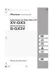
1
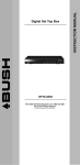
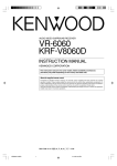
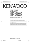
AUDIO VIDEO SURROUND RECEIVER
KR-897
KR-797
INSTRUCTION MANUAL
KENWOOD CORPORATION
This manual contains instructions for two models. Model availability and features
(functions) may differ depending on country and sales area.
Model KR-897 is not available in except for U.S.A. and Canada.
B60-3069-00 CS (K, P, Y) MC
98/12 11 10 9 8 7 6 5 4 3 2 1 97/12 11 10 9 8 7 6 5 4 3 2 1
KR-897̲797(En).pm5
1
07.6.11, 5:05 PM
Before applying power
KR-897/KR-797 (En)
2
Before applying power
3 Caution : Read this section carefully to ensure safe operation.
Units are designed for operation as follows.
U.S.A. and Canada ........................................... AC120 V only
Australia ....................................................... AC 240 V only
Europe and U.K. .............................................. AC 230 V only
China and Russia ............................................ AC 220 V only
*Other countries ..................... AC 110-120/220-240 V switchable
*AC voltage selection
AC voltage selector switch
ANTENNA
VIDEO 2
PLAY IN
75μs
AM 10kHz
FM 100kHz
DE−
EMPHASIS
CHANNEL
SPACE
50μs
L
AC 110120V〜
R
OUT
PLAY IN
FM
75Ω
IN
ADAPTOR
R
REC OUT
VIDEO 1
/TAPE 1
PHONO
GND
L
PLAY
IN
R
CD
R
L
L
SUBWOOFER
PRE OUT
FRONT SPEAKERS
( 8−16Ω)
C
SYSTEM
CONTROL
ƒ
AUDIO
AC 220240V〜
R
TAPE 2
MONITOR
FM
300Ω
Safety precautions
L
REC OUT
AM 9kHz
FM 50kHz
AM
Note:
Our warranty does not cover damage caused by excessive line voltage
due to improper setting of the AC voltage selector switch.
AC 220240V〜
AC 110120V〜
The AC voltage selector switch on the rear panel is set to the voltage
that prevails in the area to which the unit is shipped. Before connecting
the power cord to your AC outlet, make sure that the setting position
of this switch matches your line voltage. If not, it must be set to your
voltage in accordance with the following direction.
SURROUND
SPEAKERS
( 4−8Ω)
CENTER
SPEAKER
( 8−16Ω)
SWITCHED
AC 110-120V/AC 220-240V〜
+
+
−
−
R
50/60Hz
L
Move switch lever to match your line voltage
with a small screwdriver or other pointed tool.
3 Caution : Read this section carefully to ensure safe operation.
WARNING : TO PREVENT FIRE OR ELECTRIC SHOCK, DO NOT EXPOSE THIS
APPLIANCE TO RAIN OR MOISTURE.
CAUTION
RISK OF ELECTRIC SHOCK
DO NOT OPEN
CAUTION: TO REDUCE THE RISK OF ELECTRIC SHOCK, DO NOT REMOVE COVER
(OR BACK). NO USER-SERVICEABLE PARTS INSIDE, REFER SERVICING TO QUALIFIED SERVICE PERSONNEL.
THE LIGHTNING FLASH WITH ARROWHEAD SYMBOL, WITHIN AN EQUILATERAL TRIANGLE, IS INTENDED TO ALERT THE USER TO THE PRESENCE OF UNINSULATED “DANGEROUS VOLTAGE” WITHIN
THE PRODUCT’S ENCLOSURE THAT MAY BE OF SUFFICIENT MAGNITUDE TO CONSTITUTE A RISK OF
ELECTRIC SHOCK TO PERSONS.
THE EXCLAMATION POINT WITHIN AN EQUILATERAL TRIANGLE IS INTENDED TO ALERT THE USER TO
THE PRESENCE OF IMPORTANT OPERATING AND MAINTENANCE (SERVICING) INSTRUCTIONS IN THE
LITERATURE ACCOMPANYING THE APPLIANCE.
Unpacking
Unpack the unit carefully and make sure that all accessories are put aside so they will not be lost. Examine the unit for any possibility of shipping damage.
If your unit is damaged or fails to operate, notify your dealer immediately. If your unit was shipped to you directly, notify the shipping company without delay.
Only the consignee (the person or company receiving the unit) can file a claim against the carrier for shipping damage. We recommend that you retain the
original carton and packing materials for use should you transport or ship the unit in the future.
Accessories
FM indoor antenna (1)
AM loop antenna (1)
Loop antenna stand (1)
Remote control unit (1)
Batteries (R6/AA) (2)
Shorting pins (2)
(KR-797 only)
KR-897̲797(En).pm5
2
07.6.11, 5:05 PM
KR-897/KR-797 (En)
Special features
3
DOLBY PRO LOGIC & DOLBY 3 STEREO
The surround system reproduces video software programs carrying the
mark with similar acoustic effects to movie
theaters.
The DOLBY PRO LOGIC mode controls the audio signals of the Front Left/Right, Center and Rear surround channels using the built-in
directivity enhancer circuit to reproduce the feeling of sound motions very realistically.
The DOLBY 3 STEREO mode can reproduce the motions of sound even when only the front and center speakers are used, by providing proper
acoustic position using the directivity enhancer circuit.
SRS 3D Stereo
The SRS (Sound Retrieval System) is an innovative system simulating a 3-dimensional sound space, which features clearly improved
feelings of depth, sound field extension and acoustic image positioning as well as a widened listening area.
Caution : Read the pages marked 3 carefully to
ensure safe operation.
Contents
Before applying power ............................................................................................................................................................................................. 2
3 Before applying power ......................................................................................................................................... 2
3 Safety precautions ............................................................................................................................................... 2
Special features ......................................................................................................................................................................................................... 3
System connection ..................................................................................................................................................................................................... 4
Connections of Audio and Video components (KR-897) ...................................................................................... 4
Connections of Audio and Video components (KR-797) ...................................................................................... 5
About the system control connections ................................................................................................................. 6
Connection of speakers (KR-897) ........................................................................................................................ 7
Connection of speakers (KR-797) ........................................................................................................................ 8
Connection of antenna ......................................................................................................................................... 9
FM DE-EMPHASIS / CHANNEL SPACE switch .................................................................................................. 10
Controls and indicators ........................................................................................................................................................................................... 11
Operation of remote control unit ........................................................................................................................................................................... 12
Playing music ............................................................................................................................................................................................................ 14
Sound adjustment functions .................................................................................................................................................................................. 15
Recordin ..................................................................................................................................................................................................................... 18
Broadcast receptiong .............................................................................................................................................................................................. 19
Receiving broadcast stations ............................................................................................................................ 19
Receiving radio stations by specifying its frequency ......................................................................................... 20
Storing radio stations in memory (Station preset) ............................................................................................. 21
Receiving a preset station ................................................................................................................................. 21
Receiving all preset stations in order (P. CALL) .................................................................................................. 21
Presence play ........................................................................................................................................................................................................... 23
Adjustments for surround play .......................................................................................................................... 24
Surround play ..................................................................................................................................................... 26
SRS 3D Stereo (Sound Retrieval System) .......................................................................................................... 27
In case of difficulty .................................................................................................................................................................................................. 28
3 Specifications ........................................................................................................................................................................................................... 30
KR-897̲797(En).pm5
3
07.6.11, 5:05 PM
System connection
KR-897/KR-797 (En)
4
Connections of Audio and Video components (KR-897)
Make connection as shown below.
When connecting the related system components, refer
also to the instruction manuals of the related components.
3 Do not plug in the power lead until all connections are
completed.
Malfunction of microcomputer
If operation is not possible or erroneous display appears even
though all connections have been made properly, reset the microcomputer referring to “In case of difficulty”.
•
Cassette deck 1, MD recorder
or VCR 1
Cassette deck
KX-W597/KX-W797*3
OUT
Audio
IN
*1 System
control cord
Video deck 2 or DVD/LD player
Power amplifier
KM-897*3
Audio OUT
*2 Cassette deck 2
REC
IN
PLAY
OUT
CENTER
FRONT
VIDEO 2
PLAY IN
L
REC OUT
TAPE 2
MONITOR
ANTENNA
AM
PLAY IN
FM
300Ω
FM
75Ω
FRONT
SURROUND
PRE OUT
FRONT SPEAKERS
( 8−16Ω)
REC OUT
L
PLAY
IN
R
CD
−
(ƒ)
AUDIO
R
L
SWITCHED
+
VIDEO 1 SYSTEM
/TAPE 1 CONTROL
PHONO
GND
To wall
AC outlet
R
R
SUBWOOFER
PRE OUT
L
÷ Do not connect up a power source which is
larger than that indicated on the socket at the
rear of the unit.
System control cord
PGM FILE
Multipul CD player
DP-R797
Turntable
KR-897̲797(En).pm5
4
*1 The system control cord should be connected when a
KENWOOD audio component system is connected.
*2 Do not connect system control cord to the cassette
deck connected to the TAPE 2 MONITOR jacks.
*3 The KX-W797 and KM-897 are not marketed in other
areas than the USA and Canada.
07.6.11, 5:05 PM
System connection
KR-897/KR-797 (En)
Connections of Audio and Video components (KR-797)
Make connection as shown below.
When connecting the related system components, refer
also to the instruction manuals of the related components.
3 Do not plug in the power lead until all connections are
completed.
Malfunction of microcomputer
If operation is not possible or erroneous display appears even
though all connections have been made properly, reset the microcomputer referring to “In case of difficulty”.
•
Video deck 1, cassette deck 1
or MD recorder
cassette deck
KX-W597/KX-W797*1
OUT
Audio
IN
*1 System
control cord
Video deck 2 or DVD/LD player
Graphic
equalizer
KE-597
Audio OUT
IN
OUT
*2 Cassette deck 2
REC
IN
PLAY
OUT
÷ Do not connect up a
power source which is
larger than that indicated on the socket at
the rear of the unit.
VIDEO 2
PLAY IN
REC OUT
TAPE 2
MONITOR
ANTENNA
AM
ADAPTOR
R
L
L
PLAY
IN
R
CD
+
L
SURROUND
SPEAKERS
( 4−8Ω)
SUBWOOFER
PRE OUT
CENTER
SPEAKER
( 8−16Ω)
SWITCHED
+
−
(ƒ)
R
FRONT SPEAKERS
( 8−16Ω)
C
VIDEO 1 SYSTEM
/TAPE 1 CONTROL
PHONO
AUDIO
To wall
AC outlet
IN
REC OUT
GND
FM
75Ω
L
R
OUT
PLAY IN
FM
300Ω
L
R
−
R
L
*1 The system control cord should be connected when a
KENWOOD audio component system is connected.
*2 Do not connect system control cord to the cassette
deck connected to the TAPE 2 MONITOR jacks.
System control cord
*3 The KX-W797 and KM-897 are not marketed in other
areas than the USA and Canada.
PGM FILE
Multipul CD player
DP-R797
Caution regarding placement
(Except for U.S.A. and Canada)
To maintain proper ventilation, be sure to leave a space around the
unit (from the largest outer dimensions including projections)
equal to, or greater than, shown below.
Left and right panels : 10 cm
Rear panel
: 10 cm
Top panel
: 50 cm
Turntable
KR-897̲797(En).pm5
5
07.6.11, 5:05 PM
5
KR-897/KR-797 (En)
6
About the system control connections
Connecting system control cords after connecting a KENWOOD audio component system lets you take advantage of convenient
system control operations.
There are two KENWOOD system control modes. Make connections according to the groups of terminal symbols shown below.
ƒ
Mode: lets you combine F , f , and
Mode: for
terminals only
ƒ
terminals
This unit is compatible with both [XS8] and [SL16] modes. It comes from the factory set to the [SL16] mode. To switch to the [XS8]
mode, follow the instructions in “SWITCHING BETWEEN [XS8] AND [SL16]” below.
EXAMPLE: [XS8] mode connections
The underlined portion represents the setting of the system
control mode.
EXAMPLE: [SL16] mode connections
The underlined portion represents the setting of the system
control mode.
Turntable
Turntable
[SL16] [XS8]
Receiver
[SL16]
MD Recorder
System
control
cord
[SL16] [XS8]
Receiver
[SL16]
MD Recorder
System
control
cord
LD Player
LD Player
[SL16] [XS] [XS8] [XR]
Cassette Deck
Turntable
[SL16] [XS] [XS8] [XR]
Cassette
Deck
Turntable
[SL16] [XS] [XS8]
Multiple
CD Player
[SL16] [XS] [XS8]
Multiple
CD Player
÷ Some CD players and cassette decks are not compatible with the [SL16] system control mode. Be sure to use the [XS8] system control mode when
making system connections with equipment that is not [SL16] compatible.
÷ Some MD players are not system control compatible. You cannot make system control connections to this kind of equipment.
1. [SL16] equipment cannot be combined with [XR], [XS], and [XS8] equipment for system operations. If your
equipment consists of this kind of combination, please do not connect any system control cords. Even
without system control cords, normal operations can be carried out without affecting performance.
2. Do not connect system control cords to any components other than those specified by KENWOOD. It may
cause a malfunction and damage your equipment.
3. Be sure the system control plugs are inserted all the way in to the system control terminals.
Notes
ABOUT THE SYSTEM CONTROL OPERATIONS
SWITCHING BETWEEN [XS8] AND [SL16]
Remote Control (possible when the system control mode
matches)
The system control mode can be switched over easily with the
following operation.
1 Unplug the AC power cord from the wall outlet.
2 Set the SYSTEM CONTROL switch on the rear panel to the desired
position.
Lets you operate source components with the system remote
supplied with this unit.
Automatic Operation (Except [XR] equipment)
When you start playback from a source component, the input
selector on this unit switches to that component automatically.
(Except TAPE 2)
Note
SYSTEM
CONTROL
Synchronized Recording (Except [XR] equipment)
Lets you synchronize recording with the start of playback when
recording from CD or MD.
(ƒ)
÷ This operation does not affect the items stored in memory.
Notes
1. Connect all cords firmly. If connections are loose, there could be loss of sound or noise produced.
2. When plugging and unplugging connection cords, be sure to first remove the power cord from the AC outlet. Plugging / unplugging connection
cords without removal of the power cord can cause malfunctions or damage to the unit.
3. If the system control cords or audio cords are not connected properly, the remote control or automatic operation between system components
will not work properly.
KR-897̲797(En).pm5
6
07.6.11, 5:06 PM
KR-897/KR-797 (En)
Connection of speakers (KR-897)
Center speaker
Powerd
(8Ω ~ 16Ω)
sub-woofer
7
Speaker system A
(8Ω ~ 16Ω)
R
L
* Connect the speakers for use in
surround play to speaker system A.
Speaker system B does not output sound during surround play.
·
·
ª
CENTER
·
L
REC OUT
R
TAPE 2
MONITOR
ANTENNA
AM
SURROUND
PRE OUT
PLAY IN
FM
300Ω
FM
75Ω
ª
FRONT
VIDEO 2
PLAY IN
FRONT
FRONT SPEAKERS
( 8−16Ω)
REC OUT
SWITCHED
+
VIDEO 1 SYSTEM
/TAPE 1 CONTROL
PHONO
GND
ª
L
PLAY
IN
R
CD
−
(ƒ)
1 Push lever.
L
R
SUBWOOFER
PRE OUT
L
R
AUDIO
+
+
−
R
L
CENTER
SPEAKER
SURROUND
(8Ω-16Ω) SPEAKERS (4Ω-8Ω)
−
CENTER
MAIN IN
50/60Hz
UNSWITCHED
2 Insert cord.
LINE IN
(SPEAKERS B)
L
L
R
R
R
+
CENTER
SPEAKER
SURROUND
(8Ω-16Ω) SPEAKERS (4Ω-8Ω)
CENTER
MAIN IN
R
–
–
L
+
SPEAKERS B (8-16Ω)
SURROUND
MAIN IN
*1 Power amplifier
KM-897
LINE IN
(SPEAKERS B)
L
3 Return lever.
R
+
R
–
–
L
+
SPEAKERS B (8Ω-16Ω)
ª
·
·
ª
*1 For the operation of the
power amplifier (KM-897),
refer to the instruction
manual of the power amplifier (KM-897).
SURROUND
MAIN IN
ª
·
ª
·
The speakers connected to the KR-897 and
KM-897 reproduce sound as described below.
When surround play is used: Speakers used for reproduction
R
R
L
SPEAKERS key: ON
Key: – SURROUND
:
:
Speaker system A/Sub-woofer
Center speaker/Surround speakers
Stereo play using the KR-897: Speakers used for reproduction
L
Speaker system B
(8Ω ~ 16Ω)
KR-897
KM-897
Surround speakers
(4Ω ~ 8Ω)
KR-897
KM-897
SPEAKERS key: ON :
POWER key: – OFF :
Speaker system A/Sub-woofer
Stereo play using the KM-897: Speakers used for reproduction
KR-897
KM-897
SPEAKERS key: OFF :
Key: - STEREO
:
Speaker system B
HEADPHONES play using only: Speakers used for reproduction
KR-897
KM-897
SPEAKERS key: OFF :
POWER key: – OFF :
÷ For the installation and adjustment of speakers for surround play £
÷ Never short-circuit the + and - speaker cords. For the symptom and remedy when a speaker cord is shorted.
•
÷ If the left and right speakers are connected inversely or if the speaker cords are connected with reversed polarity, the sound becomes unnatural with
ambiguous acoustic image positioning. Be sure to connect the speakers and speaker cords correctly.
÷ Connect a sub woofer if you want to enhance the bass sound. The connected sub-woofer should be a power sub-woofer with a built-in amp.
KR-897̲797(En).pm5
7
07.6.11, 5:06 PM
KR-897/KR-797 (En)
8
Connection of speakers (KR-797)
Powerd
sub-woofer
Center speaker
(8Ω ~ 16Ω)
Speaker system
(8Ω ~ 16Ω)
R
ª
VIDEO 2
PLAY IN
REC OUT
TAPE 2
MONITOR
ANTENNA
AM
L
R
L
PLAY
IN
R
CD
R
L
R
·
FRONT SPEAKERS
( 8−16Ω)
C
+
L
SUBWOOFER
PRE OUT
ª
SURROUND
SPEAKERS
( 4−8Ω)
·
CENTER
SPEAKER
( 8−16Ω)
·
SWITCHED
+
−
(ƒ)
AUDIO
ª
IN
VIDEO 1 SYSTEM
/TAPE 1 CONTROL
PHONO
ª
ADAPTOR
REC OUT
GND
FM
75Ω
L
R
OUT
PLAY IN
FM
300Ω
·
·
L
−
R
1 Push lever.
L
ª
2 Insert cord.
R
L
Surround speakers
(4Ω ~ 8Ω)
3 Return lever.
÷ Never short-circuit the + and - speaker cords. For the symptom and remedy when a speaker cord is shorted:
•
÷ If the left and right speakers are connected inversely or if the speaker cords are connected with reversed polarity, the sound becomes unnatural with
ambiguous acoustic image positioning. Be sure to connect the speakers and speaker cords correctly.
÷ Connect a sub woofer if you want to enhance the bass sound. The connected sub-woofer should be a power sub-woofer with a built-in amp.
ADAPTOR jacks (KR-797)
When an adaptor-type component such as a graphic equalizer is
connected, unplug the shorting pins from the ADAPTOR jacks and
connect the component to these jacks.
÷ When the ADAPTOR jacks are not used, be sure to plug the shorting
pins into jacks. Otherwise, the sound will not be produced.
÷ When the ADAPTOR jacks are used, retain the shorting pins and be
careful not to lose them.
÷ Never plug a shorting pin into other jacks than ADAPTOR jacks.
Otherwise, the unit may be damaged.
KR-897̲797(En).pm5
8
Shorting
pins
shorting
pins
L
L
R
R
OUT
IN
ADAPTOR
07.6.11, 5:06 PM
KR-897/KR-797 (En)
Connection of antenna
9
Connection method to each antenna terminal
1 Push lever.
2 Insert cord.
3 Return lever.
VIDEO 2
PLAY IN
L
L
REC OUT
R
R
TAPE 2
MONITOR
ANTENNA
OUT
AM
PLAY IN
FM
300Ω
L
R
REC OUT
FRONT SPEAKERS
( 8−16Ω)
C
+
VIDEO 1 SYSTEM
/TAPE 1 CONTROL
PHONO
GND
PLAY
IN
L
SWITCHED
+
−
−
CD
R
FM
75Ω
IN
ADAPTOR
ƒ
SURROUND
SPEAKERS
( 4−8Ω)
SUBWOOFER
PRE OUT
L
R
AUDIO
CENTER
SPEAKER
( 8−16Ω)
L
R
The illustration shows the KR-797.
AM loop antenna connection
The supplied antenna is for indoor use. Place it as far as possible from the
main system, TV set, speaker cords and power cord, and set it to a
direction which provides the best reception.
ANTENNA
AM
FM
300Ω
GND
VIDEO 2
PLAY IN
R
R
TAPE 2
MONITOR
OUT
PLAY IN
FM
300Ω
ADAPTOR
L
R
FRONT SPEAKERS
( 8−16Ω)
C
VIDEO 1 SYSTEM
/TAPE 1 CONTROL
PLAY
IN
L
SWITCHED
+
+
−
−
CD
R
FM
75Ω
IN
REC OUT
PHONO
GND
FM
75Ω
L
L
REC OUT
ANTENNA
AM
ƒ
R
AUDIO
SURROUND
SPEAKERS
( 4−8Ω)
SUBWOOFER
PRE OUT
L
CENTER
SPEAKER
( 8−16Ω)
R
L
The illustration shows the KR-797.
FM indoor antenna connection
FM outdoor antenna connection
The accessory antenna is for temporary indoor use only. For stable signal
reception we recommend using an outdoor antenna. Remove the indoor
antenna if you connect one outdoors.
Lead the 75 Ω coaxial cable connected to the FM outdoor antenna into
the room and connect it to the FM 75 Ω terminal.
When using a commercially-available
T-shaped indoor antenna (300 Ω),
connect it to these terminals.
(Remove the provided indoor antenna if you
connect a T-shaped indoor antenna.)
ANTENNA
AM
FM
300Ω
10mm 10mm
GND
VIDEO 2
PLAY IN
REC OUT
TAPE 2
MONITOR
ANTENNA
AM
PLAY IN
FM
300Ω
IN
ADAPTOR
R
L
FRONT SPEAKERS
( 8−16Ω)
C
+
VIDEO 1 SYSTEM
/TAPE 1 CONTROL
PLAY
IN
L
FM
75Ω
R
OUT
REC OUT
PHONO
GND
FM
75Ω
L
L
R
SWITCHED
+
−
−
CD
R
ƒ
AUDIO
R
L
SUBWOOFER
PRE OUT
SURROUND
SPEAKERS
( 4−8Ω)
CENTER
SPEAKER
( 8−16Ω)
R
L
The illustration shows the KR-797.
Pull out while rotating.
KR-897̲797(En).pm5
9
07.6.11, 5:06 PM
KR-897/KR-797 (En)
10
FM DE-EMPHASIS / CHANNEL SPACE switch
(Except for U.S.A. and Canada)
ANTENNA
75μs
AM 10kHz
FM 100kHz
DE−
EMPHASIS
CHANNEL
SPACE
50μs
AM 9kHz
FM 50kHz
L
R
L
AC 110120V〜
OUT
PLAY IN
FM
300Ω
ADAPTOR
R
KR-897̲797(En).pm5
10
FRONT SPEAKERS
( 8−16Ω)
C
SWITCHED
AC 110-120V/AC 220-240V〜
+
+
−
−
50/60Hz
CD
R
ƒ
AUDIO
R
REAR
SPEAKERS
( 4−8Ω)
SUB WOOFER
PRE OUT
L
CENTER
SPEAKERS
( 8−16Ω)
R
L
75μs
DE−
EMPHASIS
CHANNEL
SPACE
AM 10kHz
FM 100kHz
50μs
AM 9kHz
FM 50kHz
Area
÷ When changing the setting of the FM DE-EMPHASIS / CHANNEL
SPACE switch, first disconnect the power cord of the amplifier, then
reset the channel space switch, connect the power cord again, and turn
the power on.
L
SYSTEM
CONTROL
PLAY
IN
L
FM
75Ω
IN
REC OUT
VIDEO 1
/TAPE 1
PHONO
GND
AC 220240V〜
R
TAPE 2
MONITOR
AM
The FM DE-EMPHASIS / CHANNEL SPACE switch on the rear panel is
set to the correct setting that prevails in the area to which the unit is
shipped. However, if the FM DE-EMPHASIS / CHANNEL SPACE setting
is not matched to the area where the unit is to be used; for instance,
when you moved from area 1 to area 2 or vice versa, desired reception
of AM / FM broadcasts is not expected. In this case, change the FM DEEMPHASIS / CHANNEL SPACE setting in accordance with the area
corresponding to the table. The FM DE-EMPHASIS is switched over at
the same time.
VIDEO 2
PLAY IN
REC OUT
1
2
CHANNEL
SPACE freq.
U.S.A., Canada,
FM: 100kHz
Hawaii, South
AM: 10kHz
American countries
Other countries
07.6.11, 5:06 PM
FM: 50kHz
AM: 9kHz
FM DEEMPHASIS
75 µs
50 µs
Controls and indicators
KR-897/KR-797 (En)
11
SURROUND
indicator
3 STEREO
indicator
MEMORY indicator
Source Direct
indicator
TAPE 2 indicator
3 STEREO
SURROUND
TAPE 2
N.B. ST.
AM FM
N.B. circuit
indicator
Broadcast band
indicators
* * * * * * ;* *
1
M
kHz
MHz
Display
3 4
2
AUTO
TUNED
AUTO tuning/AUTO
stereo reception indicator
Frequency display,
Input display,
Preset channel display,
Surround mode display
STEREO
indicator
S.DIRECT
TUNED indicator
56 7
8
9
0
AUDIO-VIDEO SURROUND RECEIVER KR-897
PRO LOGIC
SRS
3D
3 STEREO
SPEAKERS
STEREO
SRS 3D
N.B.
SOURCE
DIRECT
STANDBY
INPUT SELECTOR
VOLUME CONTROL
POWER
1
2
3
4
5
6
7
8
9
+10
0
ON/STANDBY
AUTO
DIRECT MEMORY
BAND DISPLAY
TUNING
TAPE2
MONITOR
P.CALL
UP
DOWN
PHONES
SPEAKERS
!
@ #
1 POWER key
$
%^&* ( )
¡ ™ £
@AUTO key
Press to switch the power ON and OFF.
2 STANDBY indicator
3 SRS 3D indicator
Lights when the SRS 3D system is ON.
4 SPEAKERS indicator
#SPEAKERS key
Lights when the speakers are ON.
5 STEREO key
§
Press to turn the surround mode OFF.
6 DOLBY PRO LOGIC key
7 DOLBY 3 STEREO key
8 SRS 3D key
9 INPUT SELECTOR knob
*DISPLAY key
Press to select the tuning mode from the
auto tuning and manual tuning modes.(
Press and hold the AUTO key for more than
2 seconds to switch the TAPE1 display to
another input display.
$
¢
§
¶
Rotate to select the input source.
0 VOLUME CONTROL knob
! PHONES jack
Plug headphones into this jack.
Press to turn the speakers ON and OFF.
$DIRECT key
)
Press when tuning a broadcast station by
entering the digits of its frequencies.
%MEMORY key
¡
Press when registering a broadcast station in the preset memory.
^Numeric keys (1 to 0, +10)
&BAND key
(
Press to switch the broadcasting band.
Press to switch the displayed information
between the surround mode display and
input selector display.
Press and hold the DISPLAY key for more
than 2 seconds to switch the display brightness.
(TUNING keys (
,
)
(
Press to select a radio station.
)TAPE 2 MONITOR key
*
Press to monitor the sound being recorded, etc.
¡N.B. key
^
Press to compensate for the insufficiency in the base sound.
™P.CALL keys (
,
)
¡
Press to select one of the preset stations.
£SOURCE DIRECT key
^
Press to listen to the source sound with
a higher sound quality.
About the STANDBY indicator
This unit has a STANDBY indicator, the lighting of which indicates that a small amount of current is supplied to back up the internal memory of the unit.
This status is referred to as the standby mode of the unit. In this mode, the power of the unit can be switched ON from the remote control unit.
When the unit is not to be used for a long period of time, unplug the power cord from the power outlet.
KR-897̲797(En).pm5
11
07.6.11, 5:06 PM
Operation of remote control unit
KR-897/KR-797 (En)
12
Names of keys and their functions
The remote control unit provided with the receiver can also control KENWOOD cassette decks, MULTIPLE CD player and MD
recorder connected to the recieiver through system control cords. For details of the controllable functions, refer to the
instruction manuals of these components.
Model: RC-R0505
Infrared ray system
Numeric keys
POWER key
Used as the numeric keys of the input source
component being selected.
Press to switch ON/OFF the power of this
unit as well as the KENWOOD components
connected to it through system control cords.
1
2
3
POWER
4
5
6
0
7
8
9
+10
DISK SKIP
7
2
A/B +100
AUTO
1
¡
4
¢
VIDEO1
TAPE1
TUNER
CD
PHONO
Press to select the center mode in the
DOLBY PRO LOGIC surround mode.
VIDEO2
TAPE2
MONITOR
AV AUX
MUTE
INPUT keys
Refer to the remote control key correspondence table on the next page.
Press to select the input.
Note
The AV AUX key cannot be used
with the KR-897 and KR-797.
CENTER MODE key
6
MUTE key
BAND
Press to mute sound temporarily.
¢
P.CALL
VOLUME CONTROL keys
Press to adjust the volume.
CENTER
MODE
SETUP
%¢
SETUP key
LISTEN
MODE
LEVEL
CONTROL
SOUND
VOLUME
CONTROL
REMOTE CONTROL UNIT
RC-R0505
Press to select the type of the surround
mode.
%¢
LEVEL CONTROL keys
§
LISTEN MODE key
Press to set up the balance or surround play.
%¶
SOUND key
Press to adjust the tone or during setup of
the surround mode.
Press to adjust the tone.
Loading batteries
1 Remove the cover.
2 Insert batteries.
3 Close the cover.
2
2
1
1
÷ Insert two AA-size (R6 / SUM-3) batteries
as indicated by the polarity marking.
KR-897̲797(En).pm5
12
07.6.11, 5:06 PM
KR-897/KR-797 (En)
Operation procedure
13
1 Switch ON the power of the main unit.
Select the component to be remote controlled
2 with
one of the controlled component selection
3
÷ Pressing the POWER key of the remote control unit while the STANDBY
indicator is lit turns the power ON. Press the desired key after the
power has been turned ON.
÷ When two operation keys of the remote control unit are pressed
successively, press each key securely reserving an interval of more
than 1 second for each press.
keys.
Refer to the remote control key correspondence
table below and press the key for the desired
operation.
Remote control key correspondence table (For KENWOOD component control mode)
2 Controlled component
selection key
TUNER
TAPE1
CD
¢
4,¢
P.CALL keys
7
AUTO key
AUTO
Press to select the auto
tuning mode.
4,¢
(Skip key)
Recalls preset stations.
P.CALL
(Skip key)
7
7
7
(Stop key)
(Stop key)
(Stop key)
DISK SKIP
DISC SKIP key
A/B key
Press TAPE A or B
A/B +100
Press to select the disc to
be played.
6
BAND key
BAND
Press to switch the broadcast band.
1
TAPE1
(When used with a MD)
3 Operation key
4
*1
6
6
6
(Play/pause key)
(Forward play key)
(Play key)
1,¡
¡
+100
(Tuning keys)
1,¡
1,¡
1,¡
Press to tune broadcast
stations.
(Search key)
(Search key)
(Search key)
™
2
(Reverse play key)
Approximate operating range
Remote
sensor
AUDIO-VIDEO SURROUND RECEIVER KR-V797
PRO LOGIC
3 STEREO
STEREO
SRS 3D
N.B.
SOURCE
DIRECT
SRS
3D SPEAKER
INPUT SELECTOR
VOLUME CONTROL
STANDBY
POWER
1
2
3
4
5
6
7
8
9
+10
0
ON/STANDBY
AUTO
DIRECT MEMORY
BAND DISPLAY
TUNING
TAPE2
MONITOR
P.CALL
DOWN
UP
PHONES
SPEAKERS
6m
30°
30°
1
2
4
5
7
8
DISK SKIP
A/B +100
1
7
0
6
+10
9
2
6
BAND
AUTO
¡
4
¢
P.CALL
TUNER
CD
IDEO2
TAPE2
MONITOR
AV AUX
LEVEL
CONTROL
SOUND
SETUP
Notes
POWER
3
VIDEO1
TAPE1
CENTER
MODE
Model: RC-R0505
Infrared ray system
÷ * 1: No remote control key is marked MD, but the
TAPE1 key can be used to control a MD player by
switching the display of the main unit from TAPE1
to MD.
$
PHONO
MUTE
LISTENI
MODE
VOLUME
CONTROL
REMOTE CONTROL UNIT
RC-R0505
1. The supplied batteries are intended for use in operation checks. Therefore, their lives may be shorter than ordinary batteries.
2. When the remote-controllable distance gets shorter than before, replace both batteries with new ones.
3. Malfunction may occur if direct sunlight or the light of a high-frequency lighting fluorescent lamp enters the remote control light
sensor. In such a case, change the system installation position to prevent the malfunction.
KR-897̲797(En).pm5
13
07.6.11, 5:06 PM
Playing music
KR-897/KR-797 (En)
14
POWER
1
2
3
4
5
6
0
7
8
9
+10
DISK SKIP
A/B +100
7
2
6
AUTO
BAND
1
¡
4
VIDEO1
TAPE1
TUNER
CD
PHONO
VIDEO2
TAPE2
MONITOR
AV AUX
MUTE
¢
AUDIO-VIDEO SURROUND RECEIVER KR-897
PRO LOGIC
SRS
3D SPEAKERS
1
2
SOUND
3
4
5
6
7
8
9
0
SRS 3D
N.B.
SOURCE
DIRECT
INPUT SELECTOR
VOLUME CONTROL
+10
ON/STANDBY
AUTO
LEVEL
CONTROL
STEREO
STANDBY
POWER
LISTEN
MODE
CENTER
MODE
SETUP
3 STEREO
P.CALL
DIRECT MEMORY
BAND DIMMER
TUNING
TAPE2
MONITOR
P.CALL
VOLUME
CONTROL
DOWN
UP
PHONES
REMOTE CONTROL UNIT
RC-R0505
SPEAKERS
: Keys or controls to be used in this operation
1 Turn the power ON.
POWER
ON/STANDBY
2 Select the SPEAKERS key setting.
When the SPEAKERS indicator is ON:
The speakers connected to the SPEAKERS terminals on the rear
panel output sound.
SPEAKERS
SRS
3D
STANDBY
When the SPEAKERS indicator is OFF:
The speakers do not output sound. Use this setting when listening
through headphones.
SPEAKERS
The SPEAKERS indicator should light up.
÷ For the operation when the power amplifier (KM-897) is connected to
the KR-897, see 7 and refer to the instruction manual of the
KM-897.
3 Select the input source.
The input sources are switched in the following order:
1 TUNER (frequency display)
2 PHONO
3 TAPE1 (MD or VIDEO1)* 1
4 CD
5 VIDEO2
INPUT SELECTOR
The selected source is
displayed.
CD
*1: Switching the TAPE1 display to MD or VIDEO1 display
When a KENWOOD MD recorder is connected in the [SL 16] system
control mode, the TAPE 1 input should be switched to the MD input
using the following procedure.
1Select TAPE1 with the INPUT SELECTOR.
2Press and hold the AUTO key for more than 2
Note
seconds to select MD.
1 TAPE1
4
5 Adjust the volume.
2 MD
3 VIDEO1
Play the selected source.
Volume level is displayed.
VOL-68 dB
VOLUME CONTROL
To decrease
volume
KR-897̲797(En).pm5
14
DOWN
UP
To increase
volume
÷ The time taken till the volume level is displayed is variable depending
on the current operating condition.
÷ Rotating the VOLUME CONTROL at a higher speed increases the
amount of volume change (AI VOLUME function).
÷ The sound of input source cannot be listened to while TAPE 2
MONITOR is ON.
07.6.11, 5:06 PM
Sound adjustment functions
KR-897/KR-797 (En)
1
2
3
POWER
4
5
6
0
8
9
DISK SKIP
7
2
A/B +100
7
AUTO
15
+10
6
BAND
1
¡
4
VIDEO1
TAPE1
TUNER
CD
PHONO
VIDEO2
TAPE2
MONITOR
AV AUX
MUTE
¢
AUDIO-VIDEO SURROUND RECEIVER KR-897
PRO LOGIC
SRS
3D SPEAKERS
1
2
AUTO
LEVEL
CONTROL
STEREO
SRS 3D
N.B.
SOURCE
DIRECT
INPUT SELECTOR
VOLUME CONTROL
STANDBY
POWER
LISTEN
MODE
CENTER
MODE
SETUP
3 STEREO
P.CALL
SOUND
3
4
DIRECT MEMORY
5
6
7
8
BAND DIMMER
9
TUNING
0
+10
TAPE2
MONITOR
P.CALL
VOLUME
CONTROL
DOWN
UP
PHONES
REMOTE CONTROL UNIT
RC-R0505
SPEAKERS
: Keys or controls to be used in this operation
Adjusting the tone
1 Ensure that the SRS 3D and S.DIRECT
indicators are not lit.
2 Select the tone mode to be adjusted (from
BASS, MIDDLE and TREBLE).
SOUND
3 Adjust the tone
To increase
level
LEVEL
CONTROL
To decrease
level
SRS
3D
S.DIRECT
Make sure that the
light is out.
÷ If the S.DIRECT indicator is lit, press the S.DIRECT key to turn it off.
If the SRS 3D indicator is lit, press the SRS 3D key to turn it off.
Each press of the key switches the modes as follows:
(When the SRS 3D Stereo is OFF)
1 BASS
: Mode for adjusting the low frequencies.
2 MIDDLE : Mode for adjusting the middle frequencies.
3 TREBLE : Mode for adjusting the high frequencies.
4 End of setting
÷ Adjustment of SRS (Sound Retrieval System) 3D Stereo.
The level can be adjusted between -8 and
+8 with an increment or decrement of 2
per press.
+2
BASS
Display when “BASS” is selected.
¶
The displayed value changes.
BASS
-2
Adjusting the left/right sound balance
1 Ensure that the SURROUND, 3 STEREO
and S.DIRECT indicators are off.
SURROUND
3 STEREO
S.DIRECT
Make sure that the light is out.
2 Press the SETUP key.
SETUP
÷ If the SURROUND, 3STEREO or S.DIRECT indicators are lit, press the
STEREO key to turn them OFF.
3 Adjust the balance.
Position of the left speaker Indicates the center
To decrease
the left
channel sound
LEVEL
CONTROL
To decrease
the right
channel sound
Position of the right speaker
---yt- Indicates the balance setting
4 Press the SETUP key to return to the
previous input selector display.
KR-897̲797(En).pm5
15
07.6.11, 5:06 PM
KR-897/KR-797 (En)
16
POWER
1
2
3
4
5
6
0
7
8
9
+10
DISK SKIP
A/B +100
7
2
6
AUTO
BAND
1
¡
4
VIDEO1
TAPE1
TUNER
CD
PHONO
VIDEO2
TAPE2
MONITOR
AV AUX
MUTE
¢
AUDIO-VIDEO SURROUND RECEIVER KR-897
PRO LOGIC
SRS
3D SPEAKERS
SRS 3D
N.B.
SOURCE
DIRECT
INPUT SELECTOR
VOLUME CONTROL
POWER
1
LISTEN
MODE
2
SOUND
3
4
5
6
7
8
9
0
+10
ON/STANDBY
AUTO
LEVEL
CONTROL
STEREO
STANDBY
CENTER
MODE
SETUP
3 STEREO
P.CALL
DIRECT MEMORY
BAND DIMMER
VOLUME
CONTROL
TUNING
TAPE2
MONITOR
P.CALL
DOWN
UP
PHONES
REMOTE CONTROL UNIT
RC-R0505
SPEAKERS
: Keys or controls to be used in this operation
Source Direct playback
This feature allows you to play the source signal with a high quality by
passing it only through the minimum required circuitry.
Lights
1 Choose the playback source.
S.DIRECT
CD
INPUT SELECTOR
÷ During Source Direct playback, the tone controls (BASS,MIDDLE and
TREBLE), balance control and N.B. are defeated.
÷ The Source Direct playback is canceled when any key associated with
the surround play is pressed.
2 Press the SOURCE DIRECT key.
SOURCE
DIRECT
To cancel
Press the SOURCE DIRECT key again.
Goes off
S.DIRECT
CD
3 Playback the source.
Compensating for low frequencies (N.B.: Natural Bass circuit)
N.B. circuit is used to compensate for the low frequencies which are less
audible during low-volume listening.
N.B.
N.B.
CD
Lights
÷ When the S.DIRECT is selected, the N.B. control keys are not effective.
To cancel
Press the N.B. key again.
N.B.
CD
Goes off
KR-897̲797(En).pm5
16
07.6.11, 5:06 PM
KR-897/KR-797 (En)
1
2
3
POWER
4
5
6
0
8
9
DISK SKIP
7
2
A/B +100
7
AUTO
17
+10
6
BAND
1
¡
4
VIDEO1
TAPE1
TUNER
CD
PHONO
VIDEO2
TAPE2
MONITOR
AV AUX
MUTE
¢
AUDIO-VIDEO SURROUND RECEIVER KR-897
PRO LOGIC
SRS
3D SPEAKERS
1
2
SOUND
3
4
5
6
7
8
9
0
SRS 3D
N.B.
SOURCE
DIRECT
INPUT SELECTOR
VOLUME CONTROL
+10
ON/STANDBY
AUTO
LEVEL
CONTROL
STEREO
STANDBY
POWER
LISTEN
MODE
CENTER
MODE
SETUP
3 STEREO
P.CALL
DIRECT MEMORY
BAND DIMMER
TUNING
TAPE2
MONITOR
VOLUME
CONTROL
P.CALL
DOWN
UP
PHONES
REMOTE CONTROL UNIT
RC-R0505
SPEAKERS
: Keys or controls to be used in this operation
To listen through headphones
1 Press the SPEAKERS key to OFF.
SRS
3D SPEAKERS
STANDBY
SPEAKERS
Make sure the light is out.
÷ For the operation when the power amplifier (KM-897) is connected
to the KR-897, see 7 and refer to the instruction manual of the
KM-897.
2 Plug headphones.
PHONES
3 Adjust the volume.
VOLUME CONTROL
To decrease
volume
DOWN
UP
To increase
volume
To mute sound temporarily
Remote control unit only
MUTE
MUTE O N
Blinks
To cancel
Press the MUTE key again.
KR-897̲797(En).pm5
17
07.6.11, 5:06 PM
Recording
KR-897/KR-797 (En)
18
When recording sound with a recorder component of KENWOOD, synchro recording is possible by setting the INPUT SELECTOR
to select TAPE1 or MD according to the connected component.
Preparation
÷ Switch the TAPE1 display to MD or VIDEO1 with the following
operation.
1 Select TAPE1 with the INPUT SELECTOR.
2 Press and hold the AUTO key for more than 2 seconds.
Each press switches the display.
1 TAPE1
2 MD
3 VIDEO1
To record a music source
1 Select the source to be recorded.
INPUT SELECTOR
Select an input
source other than
TAPE 1.
2 Put the cassette deck in record-pause
mode.
3 Play the source and start recording.
The input sources are switched in the following order:
1 TUNER (frequency display)
2 PHONO
3 TAPE1 (MD or VIDEO1)
4 CD
5 VIDEO2
÷ The VIDEO1 display can be switched to the display of other input by
using the procedure described in “Preparation” above.
÷ For the synchro recording with a cassette deck and/or MD recorder,
refer to the respective instruction manuals..
÷ It is not possible the VIDEO1 or MD input to TAPE1 because all of these
components should use the same INPUT SELECTOR position.
Copying tape (Tape dubbing TAPE 2 = TAPE 1)
1 Press the TAPE 2 MONITOR key.
BAND DISPLAY
TUNING
TAPE2
MONITOR
Lights
TAPE 2
CD
2 Select a source other than TAPE 1.
INPUT SELECTOR
3 Play cassette deck 2 and start recording
on cassette deck 1.
÷ For copying a tape using a double cassette deck, read the instruction
manual of the double cassette deck.
Copying tape (Tape dubbing TAPE 1 = TAPE 2)
1 Select TAPE 1 with the INPUT SELECTOR control of the
main unit.
2 Play the cassette deck connected to the TAPE 1 jacks and
start recording of the cassette deck connected to the
TAPE 2 jacks.
Regarding TAPE 2 MONITOR
A cassette deck or graphic equalizer can be connected to this unit’s TAPE 2 MONITOR terminals. If you connect a graphic equalizer, turn the
TAPE 2 MONITOR key ON. If you connect a 3-head cassette deck, you can monitor the source sound, or the sound being recorded, while
recording. Pressing the TAPE 2 MONITOR key lets you compare the recorded sound and the source sound. Refer to the operating manual for
the component you connected for further details.
KR-897̲797(En).pm5
18
07.6.11, 5:06 PM
Broadcast reception
KR-897/KR-797 (En)
1
2
3
POWER
4
5
6
0
8
9
DISK SKIP
7
2
A/B +100
7
AUTO
19
+10
6
BAND
1
¡
4
VIDEO1
TAPE1
TUNER
CD
PHONO
VIDEO2
TAPE2
MONITOR
AV AUX
MUTE
¢
AUDIO-VIDEO SURROUND RECEIVER KR-897
PRO LOGIC
SRS
3D SPEAKERS
1
2
3
SOUND
4
5
6
7
8
9
SRS 3D
N.B.
SOURCE
DIRECT
INPUT SELECTOR
VOLUME CONTROL
+10
0
ON/STANDBY
AUTO
LEVEL
CONTROL
STEREO
STANDBY
POWER
LISTEN
MODE
CENTER
MODE
SETUP
3 STEREO
P.CALL
DIRECT MEMORY
BAND DIMMER
TAPE2
MONITOR
TUNING
P.CALL
VOLUME
CONTROL
UP
DOWN
PHONES
REMOTE CONTROL UNIT
RC-R0505
SPEAKERS
: Keys or controls to be used in this operation
Receiving broadcast stations
1 Select the TUNER input.
The input sources are switched in the following order:
1TUNER (frequency display)
2PHONO
3TAPE1 (MD or VIDEO1)* 1
4CD
5VIDEO2
INPUT SELECTOR
Frequency display
8 9 .0 0
÷ The last frequency tuned before is displayed.
÷ *1: How to switch the display
2 Select the broadcast band.
MHz
*$
Each press switches the band as follows:
BAND DISPLAY
TUNING
TAPE2
MONITOR
1 FM
2 AM
FM
--
8 9 .0 0
AUTO
MHz
“AM” or “FM” indicator
3 Select the tuning method.
Each press switches the turning method as follows:
1 AUTO lit (auto tuning)
2 AUTO not lit (manual tuning)
AUTO DIRECT MEMORY
8 9 .0 0
AUTO
MHz
Lights
÷ Usually, set the switch to AUTO (auto tuning).
Select manual tuning when noise interferes due to weak radio wave.
(The stereo broadcasting is received in monaural during manual tuning.)
4 Select a station.
Frequency display
To increase frequency
BAND DISPLAY
To decrease
frequency
TUNING
TAPE2
MONITOR
FM
--
8 9 .0 0
AUTO
MHz
TUNED
“TUNED” lights up when a
station is tuned.
Auto tuning
: The next station found is tuned automatically.
Manual tuning : Press repeatedly or hold until a station is tuned.
÷ The same operation is also available with the
remote control unit.
KR-897̲797(En).pm5
19
07.6.11, 5:06 PM
1
and
¡
keys of the
KR-897/KR-797 (En)
20
POWER
1
2
3
4
5
6
0
7
8
9
+10
DISK SKIP
A/B +100
7
2
6
AUTO
BAND
1
¡
4
VIDEO1
TAPE1
TUNER
CD
PHONO
VIDEO2
TAPE2
MONITOR
AV AUX
MUTE
¢
AUDIO-VIDEO SURROUND RECEIVER KR-897
PRO LOGIC
SRS
3D SPEAKERS
1
2
3
SOUND
4
5
6
7
8
9
0
SRS 3D
N.B.
SOURCE
DIRECT
INPUT SELECTOR
VOLUME CONTROL
+10
ON/STANDBY
AUTO
LEVEL
CONTROL
STEREO
STANDBY
POWER
LISTEN
MODE
CENTER
MODE
SETUP
3 STEREO
P.CALL
DIRECT MEMORY
BAND DIMMER
TUNING
TAPE2
MONITOR
P.CALL
VOLUME
CONTROL
UP
DOWN
PHONES
REMOTE CONTROL UNIT
RC-R0505
SPEAKERS
: Keys or controls to be used in this operation
Receiving radio stations by specifying its frequency
1
The input sources are switched in the following order:
Select the TUNER input.
1TUNER (frequency display)
2PHONO
3TAPE1 (MD or VIDEO1)
4CD
5VIDEO2
Frequency display
INPUT SELECTOR
FM
2 Select the broadcast band.
AUTO
MHz
Each press switches the band as follows:
BAND DISPLAY
TUNING
1 FM
2 AM
TAPE2
MONITOR
FM
3
8 9 .0 0
--
8 9 .0 0
--
AUTO
MHz
“AM” or “FM” indicator
Specify the frequency.
Blinks
1 Press the DIRECT key.
AUTO DIRECT MEMORY
FM
FM _
.
AUTO
MHz
Press the numeric keys according to the frequency to be tuned as
shown below.
*AM10kHz/FM100kHz territories (U.S.A., Canada, etc.)
AM 810 kHz ............ 8, 1
( 10 kHz space)
AM 1260 kHz ............ 1, 2, 6
( 10 kHz space)
FM
89 MHz ............ 8, 9, )
(100 kHz space)
FM 92.5 MHz ............ 9, 2, 5
(100 kHz space)
2 Enter the frequency of the desired
station.
1
2
3
4
5
6
7
8
*AM9kHz/FM50kHz territories (other countries)
AM 810 kHz ............ 8, 1, )
( 9
AM 1260 kHz ............ 1, 2, 6, )
( 9
FM
89 MHz ............ 8, 9, ), )
( 50
FM 92.5 MHz ............ 9, 2, 5, )
( 50
kHz
kHz
kHz
kHz
space)
space)
space)
space)
0
*FM DE-EMPHASIS/CHANNEL SPACE switch
Frequency indicator
FM
--
8 9 .0 0
AUTO
MHz
TUNED
“TUNED” lights up when a station is tuned.
÷ If you make a mistake, the frequency display blinks for a few seconds.
In this case, repeat step 3 from the beginning.
KR-897̲797(En).pm5
20
07.6.11, 5:06 PM
KR-897/KR-797 (En)
Preparation
÷ Select the TUNER input.
1
2
3
POWER
4
5
6
0
8
9
DISK SKIP
7
2
A/B +100
7
AUTO
21
+10
6
BAND
1
¡
4
VIDEO1
TAPE1
TUNER
CD
PHONO
VIDEO2
TAPE2
MONITOR
AV AUX
MUTE
¢
AUDIO-VIDEO SURROUND RECEIVER KR-897
PRO LOGIC
SRS
3D SPEAKERS
1
2
SOUND
3
4
5
6
7
8
9
0
SRS 3D
N.B.
SOURCE
DIRECT
INPUT SELECTOR
VOLUME CONTROL
+10
ON/STANDBY
AUTO
LEVEL
CONTROL
STEREO
STANDBY
POWER
LISTEN
MODE
CENTER
MODE
SETUP
3 STEREO
P.CALL
DIRECT MEMORY
BAND DIMMER
TUNING
TAPE2
MONITOR
P.CALL
VOLUME
CONTROL
DOWN
UP
PHONES
REMOTE CONTROL UNIT
RC-R0505
SPEAKERS
: Keys or controls to be used in this operation
Storing radio stations in memory (Station preset)
1 Select the receiving band.
2 Select a station or frequency.
3 Press the MEMORY key during receiving
a station.
Lights up (for 5 sec.)
Lights up (for 5 sec.)
AUTO DIRECT MEMORY
FM
Proceed to step 4 within 5 sec.
(If more than 5 sec. have elapsed, press the
MEMORY key again.)
4 Select one of the preset numbers from 1
to 30.
1
2
3
4
5
6
7
8 9 .0 0
0-
M
AUTO
MHz
Press the numeric keys in the following order.
To store in “15” ... 0, 5
To store in “20” ... 0, 0, )
8
÷ Repeat steps 1 ~ 4 for each of the stations to be stored in memory.
÷ If a station is stored in a preset number which has already stored a
station memory under it, the previous memory is replaced by the new
memory content.
Receiving a preset station
Press the preset number of the desired
station.
1
2
3
4
5
6
7
8
Press the numeric keys in the following order.
To recall “15” ... 0, 5
To recall “20” ... 0, 0, )
÷ If you make a mistake in entering the figure of 10, press the 0 key
repeatedly until the original display is shown, then enter the correct
number.
Preset number stored in memory
FM
8 9 .0 0
15
AUTO
Receiving all preset stations in order (P. CALL)
÷ Every time the key is pressed, the next station in the order of the preset
number is received.
The preset number
increases.
4
¢
¢
When you press
When you press
P.CALL
4
key,
1
2
3
28
29
30
key,
1
2
3
28
29
30
P.CALL
P.CALL
The preset number
decreases.
If the key is held pressed ............... Preset stations will be received successively for about half a second each.
÷ The same operation is also available with the
main unit.
KR-897̲797(En).pm5
21
07.6.11, 5:06 PM
P.CALL
keys of the
KR-897/KR-797 (En)
22
KR-897̲797(En).pm5
22
07.6.11, 5:06 PM
Presence play
KR-897/KR-797 (En)
The surround modes allow you to enjoy the feeling of presence in music. Select the mode according to the source or components
played. For the connections of the surround and/or center speakers, refer to “Connection of speakers”.
78
DOLBY PRO LOGIC surround mode
In case center speaker is not used
Video, DVD and LD software programs carrying the
mark contain recording of the same Dolby Surround data as
those used in movie theaters.
The DOLBY PRO LOGIC surround mode uses
the Dolby Surround data and brings into
home a similar sound field with full of presence to movie theatres.
To use this mode, connect the surround
(and center) speakers.
Center speaker
TV
TV
Front speaker
Front speaker
Surround speaker
Surround speaker
DOLBY 3 STEREO mode
Center speaker
If the left and right speakers are installed apart from each other,
the center acoustic image (words, etc.) may vary depending on
the listener’s position. The DOLBY 3 STEREO mode provides an
improved positioning of the center acoustic image regardless of
the listening position.
Use this mode when playing videotape, DVD or LD software
carrying the
mark.
To use this mode, connect the center speaker.
TV
Front speaker
Recommended speaker installation
It is recommended that the surround speakers are installed straight to the left and right of the listening position or slightly behind,
at a height of about 1 meter higher than the listener’s ears. Each surround speaker should be installed so that the longer sides are
horizontal.
KR-897̲797(En).pm5
23
07.6.11, 5:06 PM
23
KR-897/KR-797 (En)
24
To improve the feeling of presence in the surround modes,
various parameters of each surround mode can be set up
according to the speaker system used as well as to the
environmental of the listening room. The following procedure let you set the parameters of the surround mode (DOLBY
PRO LOGIC, DOLBY 3 STEREO).
Once the settings have been done, it is held in memory so readjustment is not necessary even after the mode has been
changed to other modes.
POWER
1
2
3
4
5
6
0
7
8
9
+10
DISK SKIP
A/B +100
7
2
6
AUTO
BAND
1
¡
4
VIDEO1
TAPE1
TUNER
CD
PHONO
VIDEO2
TAPE2
MONITOR
AV AUX
MUTE
¢
AUDIO-VIDEO SURROUND RECEIVER KR-897
PRO LOGIC
SRS
3D SPEAKERS
1
2
SOUND
3
4
5
6
7
8
9
0
SRS 3D
N.B.
SOURCE
DIRECT
INPUT SELECTOR
VOLUME CONTROL
+10
ON/STANDBY
AUTO
LEVEL
CONTROL
STEREO
STANDBY
POWER
LISTEN
MODE
CENTER
MODE
SETUP
3 STEREO
P.CALL
DIRECT MEMORY
TUNING
BAND DIMMER
TAPE2
MONITOR
P.CALL
VOLUME
CONTROL
DOWN
UP
PHONES
REMOTE CONTROL UNIT
RC-R0505
SPEAKERS
: Keys or controls to be used in this operation
Adjustments for surround play
1 Select the DOLBY PRO LOGIC surround mode.
÷ Select a surround mode according to the played source and your
system components.
PRO LOGIC
Lights
SURROUND
PROLOG IC
2 Select the CENTER MODE.
Each press of CENTER MODE key switches the modes as follows:
1 NORMAL
CENTER
MODE
3 Adjust the front speaker balance.
1 Press the SETUP key (on the remote control unit).
SETUP
: When the center speaker is a compact
speaker.
2 WIDEBAND : When the center speaker is a large speaker.
3 PHANTOM : When no center speaker is used.
Adjustment procedure: Each press of the SETUP key switches the
adjusted items as shown below.
3 Adjusting the front speaker balance
4 Adjusting the volume level of each speaker
5 Adjusting the delay time
End of setup
To cancel setup in the middle, press the SETUP key repeatedly until the
setup mode is cancelled.
2 Adjust the front speaker (left & right)
levels so that the left and right levels are
identical.
Left speaker
position
To decrease the
left channel sound
SURROUND
LEVEL
CONTROL
To decrease the
right channel sound
---yt- Balance setup
3 Press the SETUP key again to establish
the setup.
After this, the unit enters the condition
for “4 Adjust the volume level of each
speaker”.
KR-897̲797(En).pm5
24
Right speaker
position
Center position
indication
07.6.11, 5:06 PM
KR-897/KR-797 (En)
How to calculate the
proper delay time
Assuming that the distance from
the front speakers is A meters and
that from the surround speakers is
B meters:
Front
speakers
Example:
When A = 3 m,B = 3 m,
the delay time is 20 ms.
Am
8
Bm
Surround
speakers
What is delay time?
1 Use the delay time calculation
chart on the right.
29
29
29
7
2 Use the following
formula for calculation.
29
6
5
29
4
A (m)
Delay time =
20 + 3 x (A - B) (Unit: ms)
3
26
26
26
26
26
26
2
23
23
23
23
23
23
23
20
20
20
20
20
17
17
17
17
25
16
16
16
16
20 17 16
20
20
1
17
17
1
16
2
3
4
5
6
7
8
B (m)
The sound entering the ears include the direct sound coming from the sound source and the indirect sounds reflected from the walls, floor,
ceiling, etc. The indirect sounds are delayed because they travel longer distance required for reflection before they reach the ears. The delay
time is the difference in time between the direct sound and indirect sounds.
4 Adjust the volume level of each speaker.
1 Ensure that “TEST L” is displayed. Test
tone will be output from each speaker.
2 Adjust the volume levels of the center
speaker and surround speakers with reference to the front speaker (left & right)
levels.
÷Noise-like test tone moves across speakers at intervals of 1.5 seconds.
TEST L (Front speaker, left)
TEST C (Center speaker)
(Only when NORMAL or WIDE BAND is selected in step 2)
TEST R (Front speaker, right)
TEST S (Surround speakers)
(Only when PRO LOGIC is selected in step 1)
(1) While test tone is output from the
speaker(s) to be adjusted,
(2) Adjust the speaker level.
To increase
LEVEL
CONTROL
To decrease
3 After having adjusted all of the speaker
levels, establish the setup.
SETUP
SURROUND
TEST 5
Display when test tone is output from surround speakers
÷ Be sure to adjust from the listening position.
÷ Each press of a LEVEL CONTROL key varies the level by 1 dB.
÷ The volume level can be adjusted in the range from -10 to +10 dB.
÷ The front speaker (left & right) levels cannot be varied with the LEVEL
CONTROL keys.
÷ Adjust the volume level from each of the center speaker and surround
speakers while test tone it output from the corresponding speaker.
After this, the unit enters the condition
for “5 Adjust the delay time”.
5 Adjust the delay time.
1 Ensure that the delay time adjustment
display is displayed.
2 Adjust the delay time.
÷ Check the proper delay time for your listening room by referring to
“How to calculate the proper delay time”.
÷ Select an integer value which is closest to the value obtained with
“How to calculate the proper delay time”.
÷ The delay time can be adjusted to 15, 20, 25 or 30 ms.
To increase
LEVEL
CONTROL
To decrease
3 Establish the setup.
SETUP
SURROUND
-11
X-Adjustment
position
This is the end of setup (the unit returns
to the condition before starting the setup
operations).
KR-897̲797(En).pm5
25
Front speaker
side
Surround speaker
side
07.6.11, 5:06 PM
20
Delay time
KR-897/KR-797 (En)
26
When playing videotape (DVD or LD) software carrying the
mark, a sound field with enhanced surround
effects can be enjoyed by using the DOLBY PRO LOGIC or
DOLBY 3 STEREO mode.
Be sure to complete “Adjustments for surround play” prior
to starting playback in one of these surround modes.
¢
POWER
1
2
3
4
5
6
0
7
8
9
+10
DISK SKIP
A/B +100
7
2
6
AUTO
BAND
1
¡
4
VIDEO1
TAPE1
TUNER
CD
PHONO
VIDEO2
TAPE2
MONITOR
AV AUX
MUTE
¢
AUDIO-VIDEO SURROUND RECEIVER KR-897
PRO LOGIC
SRS
3D SPEAKERS
SRS 3D
N.B.
SOURCE
DIRECT
INPUT SELECTOR
VOLUME CONTROL
POWER
1
2
SOUND
3
4
5
6
7
8
9
0
+10
ON/STANDBY
AUTO
LEVEL
CONTROL
STEREO
STANDBY
LISTEN
MODE
CENTER
MODE
SETUP
3 STEREO
P.CALL
DIRECT MEMORY
BAND DIMMER
TUNING
TAPE2
MONITOR
P.CALL
VOLUME
CONTROL
DOWN
UP
PHONES
REMOTE CONTROL UNIT
RC-R0505
SPEAKERS
: Keys or controls to be used in this operation
Surround play
1 Select one of the surround modes.
1 Select the desired surround mode.
LISTEN
MODE
Each press of LISTEN MODE key switches the modes as
follows:
1 STEREO
2 PRO LOGIC
3 3 STEREO
÷ The surround modes can also be selected directly using the
corresponding keys on the main unit.
Lights
SURROUND
PROLOG IC
Example when DOLBY PRO LOGIC is selected
2 Play a video software program.
3 Adjust the volume.
To cancel the SURROUND play
On the remote control unit, the following modes are switched every time
the LISTEN MODE key is pressed.
1 STEREO
2 PRO LOGIC
3 3 STEREO
Goes off
SURROUND
STEREO
LISTEN
MODE
Main unit
STEREO
Remote control unit
Manufactured under licence from Dolby Laboratories Licensing Corporation.
“Dolby”, “Pro Logic” and the double - D symbol are trademarks of Dolby Laboratories Licensing Corporation.
KR-897̲797(En).pm5
26
07.6.11, 5:06 PM
KR-897/KR-797 (En)
The Sound Retrieval System is an epochal system which
produces a three-dimensional sound space by applying the
most suitable processing to the sound signal on the basis of
the human listening mechanism. This permits real depth
and sound location, considered as difficult to realize with
conventional 2-channel stereo (general stereo). A sufficient
effect can be obtained for any source (CD, tape, broadcasts,
etc.).
1
2
3
POWER
4
5
6
0
8
9
DISK SKIP
7
2
A/B +100
7
AUTO
27
+10
6
BAND
1
¡
4
VIDEO1
TAPE1
TUNER
CD
PHONO
VIDEO2
TAPE2
MONITOR
AV AUX
MUTE
¢
AUDIO-VIDEO SURROUND RECEIVER KR-897
PRO LOGIC
SRS
3D SPEAKERS
SRS 3D
N.B.
SOURCE
DIRECT
INPUT SELECTOR
VOLUME CONTROL
POWER
1
2
SOUND
3
4
5
6
7
8
9
0
+10
ON/STANDBY
AUTO
LEVEL
CONTROL
STEREO
STANDBY
LISTEN
MODE
CENTER
MODE
SETUP
3 STEREO
P.CALL
DIRECT MEMORY
BAND DIMMER
TUNING
TAPE2
MONITOR
P.CALL
VOLUME
CONTROL
DOWN
UP
PHONES
REMOTE CONTROL UNIT
RC-R0505
SPEAKERS
: Keys or controls to be used in this operation
SRS 3D Stereo (Sound Retrieval System)
Adjusting the tone.
Goes off
1 Ensure that the S.DIRECT indicator is not
lit.
2 Turn the SRS 3D stereo ON.
SRS 3D
S.DIRECT
CD
Each press of the key switches the modes as follows:
1 SRS 3D is lit
................. SRS 3D STEREO ON
2 SRS 3D is not lit
............... SRS 3D STEREO OFF
SRS
3D SPEAKERS
STANDBY
3 Abjust the effect strength (level).
(1) “CENTER” or “SPACE” should be displayed.
SOUND
Increasing the “CENTER” level enhances the feeling of depth around
the center.
Lights
Each press of the key switches the modes as follows:
1 CENTER : Mode for adjusting the depth of SRS 3D.
2 SPACE
: Mode for adjusting the expansion of SRS 3D.
3 End of setting
÷ The BASS, MIDDLE and TREBLE adjustments are not available while
the SRS 3D Stereo is ON. For the BASS, MIDDLE and TREBLE
adjustment procedures:
%
Increasing the “SPACE” level makes
the sound expansion wider.
(2) Adjust the level.
CENTER
Display when CENTER is selected
To increase
the level
LEVEL
CONTROL
To decrease
the level
CENTER
3
Level display
5
The level value varies
÷ Adjustment is possible in the range from 1~7.
÷ Please set as desired according to the titles being played back etc.
Even if the sound is recorded while the SRS 3D stereo
effect is applied, the effect is not recorded together with
the source sound.
KR-897̲797(En).pm5
27
07.6.11, 5:06 PM
In case of difficulty
KR-897/KR-797 (En)
28
What appears to be a mulfunction may not always be serious. If your unit should not perform as expected, consult the table
below to see if the problem can be corrected before seeking help from your dealer or service representative.
Operation to reset
1 Unplug the AC power plug from the wall outlet.
2 While holding the POWER switch depressed, plug the AC
plug into the power outlet.
The microcomputer may fall into malfunction (impossibility to
operate, erroneous display, etc.) when the power cord is unplugged
while power is ON or due to an external factor. In this case, execute
the following procedure to reset the microcomputer and return it to
normal condition.
÷ Please note that resetting the microcomputer clears the contents
stored in and returns to the condition when it left the factory.
Amplifier
Remedy
Cause
Symptom
Sound is not output or the volume level is
low.
÷ Connect them properly referring to “Connection of speakers”.
78
÷ Press the MUTE key to OFF.
&
÷ The speaker cords are disconnected.
÷ MUTE is ON.
(The MUTE ON indicator is blinking)
÷ The SPEAKERS keys are set to OFF.
÷ The TAPE 2 MONITOR key is set to ON.
The STANDBY indicator blinks and sound is
not output.
÷ Set the SPEAKERS key to ON.
$
÷ Set the TAPE 2 MONITOR key to OFF.
Set the input selector to the position other than
tuner.
÷ Turn the power off, eliminate the short-circuiting, then turn on the power again.
÷ Speaker cords are short-circuited.
78
Sound is not output from one of the speakers.
÷ The speaker cord is disconnected.
÷ The BALANCE control is set to an extreme
position.
÷ Connect it properly referring to “Connection of
speakers”.
78
÷ Adjust the Left/Right balance.
%
Sound is not output from the surround
speaker and/or center speaker, or their sound
is very small.
÷ The surround speaker cords and/or center speaker
cord are disconnected.
÷ The Surround play mode has not been engaged.
÷ The surround and center speaker levels are set to
the minimum positions.
÷ Connect them properly referring to “Connection of speakers”.
78
÷ Set the presence mode.
¢
÷ Adjust the surround and center speaker levels.
A hum noise is generated when the PHONO
input is selected.
÷ The audio cord from the turntable is not inserted
securely into the PHONO jacks.
÷ The turntable is not grounded.
÷ Insert the audio cord plugs securely into the
PHONO jacks.
45
÷ Connect the grounding wire to the GND terminal on the rear panel.
System control is not available when TAPE1
or MD is selected.
÷ “TAPE1” or “MD” is not displayed.
÷ Switch the display to TAPE 1 or MD.
System control is not available.
÷ The XS8 and SL16 modes were switched while
the AC plug is left plugged into the wall power
outlet.
÷ Unplug the AC plug from the wall outlet and
switch the XS8 or SL16 mode as required.
÷ The setting is not correct.
÷ Adjust the brightness with the DISPLAY key.
Display is dimly lit.
$*
6
!
Tuner
Symptom
Radio stations cannot be received.
Interference.
Cause
Remedy
÷ No antenna is connected.
÷ The broadcast band is not set properly.
÷ The frequency of the desired station is not tuned.
÷ Connect an antenna.
9
÷ Set the broadcast band properly.
(
÷ Tune the frequency of the desired station.
÷ Noise due to ignition noise of an automobile.
÷ Install the outdoor antenna away from the
road.
÷ Turn off the power to the appliance.
÷ Noise due to an influence from an electric appliance.
÷ Noise due to a nearby TV set.
A station which was preset cannot be received by pressing the corresponding numeric key.
KR-897̲797(En).pm5
28
÷ The preset station belongs to a frequency that
cannot be received.
÷ The preset memory was cleared because the
power cord had been unplugged for a long period
of time.
÷ The TUNER input is not selected.
(
÷ Install the system farther away from the TV
set.
÷ Preset a station with a receivable frequency.
÷ Preset the station again.
÷ Select the TUNER input.
07.6.11, 5:06 PM
¡
¡
KR-897/KR-797 (En)
29
Remote control unit
Cause
Remedy
÷ Batteries are exhausted.
÷ The remote control unit is too far away from the
main system, controlling angle is too large, or
there is an obstacle in between.
÷ The audio cords and system control cords are not
connected properly.
÷ The source component to be operated does not
contain the tape(s) or CD.
÷ An attempt is made to play a tape which is being
recorded in the cassette deck.
÷ Replace with new batteries.
@
÷ Operate the remote control unit within the
controllable range.
#
Symptom
Remote control operation is not possible.
÷ Connect properly referring to “System connection”.
45
÷ Place the tape(s) or CD in the source component to be played.
÷ Wait until the recording is completed.
Memory backup function
Please note that the following items will be deleted from
this unit’s memory if the power cord is disconnected
from the AC outlet or the main power switch is turned off
for approximately three days.
÷ The power setting is cleared and the power is set to OFF.
÷ The input selection is cleared and the TUNER input is selected.
÷ The volume setting is cleared and the volume is set to -80 dB.
÷ The receiving band setting is cleared and the FM band is selected.
÷ The frequency setting is cleared and 87.5 MHz is selected.
÷ The preset station memory is cleared.
Note
Do not use contact cleaners because it could cause a malfunction. Be specially careful against contact cleaners containing oil, for
they may deform the plastic components.
For the U.S.A.
FCC WARNING
This equipment may generate or use radio frequency energy. Changes or modifications to this equipment may cause harmful interference
unless the modifications are expressly approved in the instruction manual. The user could lose the authority to operate this equipment if
an unauthorized change or modification is made.
NOTE:
This equipment has been tested and found to comply with the limits for a Class B digital device, pursuant to Part 15 of the FCC Rules.
These limits are designed to provide reasonable protection against harmful interference in a residential installation. This equipment may
cause harmful interference to radio communications, if it is not installed and used in accordance with the instructions. However, there is
no guarantee that interference will not occur in a particular installation. If this equipment does cause harmful interference to radio or
television reception, which can be determined by turning the equipment off and on, the user is encouraged to try to correct the interference by one or more of the following measures:
–– Reorient or relocate the receiving antenna.
–– Increase the separation between the equipment and receiver.
–– Connect the equipment into an outlet on a circuit different from that to which the receiver is connected.
–– Consult the dealer or an experienced radio / TV technician for help.
For the U.S.A.
Note to CATV system installer:
This reminder is provided to call the CATV system installer‘s attention to Article 820-40 of the NEC that provides guidelines for proper
grounding and, in particular, specifies that the cable ground shall be connected to the grounding system of the building, as close to the
point of cable entry as practical.
KR-897̲797(En).pm5
29
07.6.11, 5:06 PM
Specifications of KR-797 (for U.S.A. and Canada)
KR-897/KR-797 (En)
3Caution : Read this page carefully to ensure safe operation.
30
Audio section
FM Tuner section
Rated power output at the STEREO operation
Tuning frequency range ...................... 87.5 MHz ~ 108 MHz
Usable sensitivity
MONO ....................................... 1.3 µV (at 75 Ω) / 13.2 dBf
(75 kHz dev., SINAD 30 dB)
50 dB quieting sensitivity
STEREO ..................................... 31.6 µV (at 75 Ω) / 41.2dBf
Total harmonic distortion (1 kHz)
MONO .................................................. 0.5 % (65 dBf input)
STEREO ................................................ 0.6 % (65 dBf input)
Signal to noise ratio (1 kHz 75 kHz dev.)
MONO ................................................. 75 dB (65 dBf input)
STEREO ............................................... 68 dB (65 dBf input)
Stereo separation (1 kHz) ............................................. 40 dB
Selectivity (IHF ±400 kHz) ............................................. 66 dB
Frequency response ........ 30 Hz ~15 kHz, + 0.5 dB, – 3.0 dB
110 watts per channel minimum RMS, both channels
driven at 8 Ω, from 40 Hz to 20,000 Hz with no more than
0.8 % total harmonic distortion. (FTC)
Power output at the SURROUND operation
Front
110 watts per channel minimum RMS, both channels
driven, at 8 Ω, 1 kHz with no more than 0.8 % total
harmonic distortion.
Center
110 watts minimum RMS at 8 Ω, 1 kHz with no more than
0.8 % total harmonic distortion.
Surround
110 watts per channel minimum RMS, at 8 Ω, 1 kHz with
no more than 0.8 % total harmonic distortion.
Total harmonic distortion .............. 0.3 % (1 kHz, 55 W, 8 Ω)
Signal to noise ratio (IHF’66)
PHONO (MM) ............................................................... 75 dB
LINE (CD) ...................................................................... 93 dB
Input sensitivity / impedance
PHONO (MM) ............................................... 3.0 mV / 47 kΩ
CD ................................................................ 220 mV / 47 kΩ
Tone controls
BASS ....................................................... ± 8 dB (at 100 Hz)
MIDDLE ................................................... ± 8 dB (at 900 Hz)
TREBLE .................................................... ± 8 dB (at 10 kHz)
N.B. circuit ..................................................... + 5 dB (80 Hz)
Output level / impedance
Sub woofer preout ......................................... 2.0 V / 600 Ω
Notes
AM Tuner section
Tuning frequency range ....................... 530 kHz ~ 1,700 kHz
Usable sensitivity (30 % mod., S/N 20 dB)
............................................................. 15 µV / (500 µV / m)
Signal to noise ratio (30 % mod., 1 mV input) ........... 48 dB
General
Power consumption ....................................................... 2.8 A
3 AC outlet
SWITCHED ....................................... 1: (300 W, 2.5 A max.)
Dimensions .......................................... W:440 mm (17-5/16”)
H:127 mm
(5”)
D:389 mm (15-5/16”)
Weight (net) ................................................... 9.0 kg (19.9 lb)
1. KENWOOD follows a policy of continuous advancements in development. For this reason specifications may be changed without notice.
2. Full performance may not be exhibited in extremely cold locations (below 0 deg.C).
KR-897̲797(En).pm5
30
07.6.11, 5:06 PM
Specifications of KR-797 (for ohter countries)
KR-897/KR-797 (En)
3Caution : Read this page carefully to ensure safe operation.
Audio section
FM Tuner section
Rated power output at the STEREO operation
Tuning frequency range ......................... 87.5 MHz~108 MHz
Usable sensitivity
MONO .......................................... 2.0 µV (at 75 Ω) / 17.2 dBf
(75 kHz dev., S/N 30 dB)
50 dB quieting sensitivity
STEREO ....................................... 35 µV (at 75 Ω) / 42.2 dBf
Total harmonic distortion (1 kHz)
MONO ................................................... 0.7 % (65 dBf input)
STEREO ................................................. 0.8 % (65 dBf input)
Signal to noise ratio (1 kHz 75 kHz dev.)
MONO .................................................. 73 dB (65 dBf input)
STEREO ................................................ 66 dB (65 dBf input)
Selectivity (IHF ± 400 kHz) ............................................. 50 dB
Stereo separation (1 kHz) .............................................. 40 dB
Frequency response ........ 30 Hz ~ 15 kHz, + 0.5 dB, – 3.0 dB
100 watts per channel minimum RMS, both channels
driven at 8 Ω, from 40 Hz to 20,000 Hz with no more than
0.7 % total harmonic distortion. (FTC)
1 kHz, 10 % THD at 8 Ω .................................. 120 W + 120 W
(DIN/IEC) from 63 Hz to 12,500 Hz,
0.7 % T.H.D., at 8 Ω ...................................... 100 W + 100 W
Power output at the Surround operation
Front
(1 kHz, 0.7 % T.H.D. at 8 Ω) ....... 100 W + 100 W
Center
(1 kHz, 0.7 % T.H.D. at 8 Ω) ...................... 100 W
Surround (1 kHz, 0.7 % T.H.D. at 8 Ω) ...................... 100 W
Front
(1 kHz, 10 % T.H.D. at 8 Ω) ........ 120 W + 120 W
Center
(1 kHz, 10 % T.H.D. at 8 Ω) ....................... 120 W
Surround (1 kHz, 10 % T.H.D. at 8 Ω) ....................... 120 W
Total harmonic distortion (1 kHz, 8 Ω) .......... 0.3 % at 50 W
Signal to noise ratio (IHF'66)
PHONO (MM) ................................................................ 75 dB
CD .................................................................................. 93 dB
Input sensitivity / impedance
PHONO (MM) ................................................ 3.0 mV / 47 kΩ
CD ................................................................. 220 mV / 47 kΩ
Output level / impedance
Sub woofer preout ......................................... 2.0 V / 600 Ω
Tone controls
BASS ........................................................ ± 8 dB (at 100 Hz)
MIDDLE .................................................... ± 8 dB (at 900 Hz)
TREBLE ..................................................... ± 8 dB (at 10 kHz)
N.B. circuit ...................................................... + 5 dB (80 Hz)
Notes
AM Tuner section
Tuning frequency range
9 kHz ..................................................... 531 kHz ~ 1,602 kHz
10 kHz ................................................... 530 kHz ~ 1,610 kHz
Usable sensitivity (30 % mod., S/N 20 dB)
.............................................................. 13 µV / (500 µV / m)
Signal to noise ratio (30 % mod., 1 mV input) ........... 50 dB
General
Power consumption ...................................................... 250 W
3 AC outlet
SWITCHED ................................. Australia1 : (300 W max.)
Dimensions ............................................................ W: 440 mm
H: 127 mm
D: 389 mm
Weight (net) ................................................................... 9.0 kg
1. KENWOOD follows a policy of continuous advancements in development. For this reason specifications may be changed without notice.
2. Full performance may not be exhibited in extremely cold locations (below 0 deg.C).
KR-897̲797(En).pm5
31
07.6.11, 5:06 PM
31
Specifications of KR-897 (for U.S.A. and Canada)
KR-897/KR-797 (En)
3Caution : Read this page carefully to ensure safe operation.
32
Audio section
FM Tuner section
Rated power output at the STEREO operation
Tuning frequency range ...................... 87.5 MHz ~ 108 MHz
Usable sensitivity
MONO ....................................... 1.3 µV (at 75 Ω) / 13.2 dBf
(75 kHz dev., SINAD 30 dB)
50 dB quieting sensitivity
STEREO ..................................... 31.6 µV (at 75 Ω) / 41.2dBf
Total harmonic distortion (1 kHz)
MONO .................................................. 0.5 % (65 dBf input)
STEREO ................................................ 0.6 % (65 dBf input)
Signal to noise ratio (1 kHz 75 kHz dev.)
MONO ................................................. 75 dB (65 dBf input)
STEREO ............................................... 68 dB (65 dBf input)
Stereo separation (1 kHz) ............................................. 40 dB
Selectivity (IHF ±400 kHz) ............................................. 66 dB
Frequency response ........ 30 Hz ~15 kHz, + 0.5 dB, – 3.0 dB
120 watts per channel minimum RMS, both channels
driven at 8 Ω, from 40 Hz to 20,000 Hz with no more than
0.8 % total harmonic distortion. (FTC)
Power output at the SURROUND operation
Front
120 watts per channel minimum RMS, both channels
driven, at 8 Ω, 1 kHz with no more than 0.8 % total
harmonic distortion.
Total harmonic distortion
........................................................ 0.3 % (1 kHz, 55 W, 8 Ω)
Signal to noise ratio (IHF’66)
PHONO (MM) ............................................................... 75 dB
LINE (CD) ...................................................................... 93 dB
Input sensitivity / impedance
PHONO (MM) ............................................... 3.0 mV / 47 kΩ
CD ................................................................ 220 mV / 47 kΩ
Tone controls
BASS ....................................................... ± 8 dB (at 100 Hz)
MIDDLE ................................................... ± 8 dB (at 900 Hz)
TREBLE .................................................... ± 8 dB (at 10 kHz)
N.B. circuit ..................................................... + 5 dB (80 Hz)
Output level / impedance
Sub woofer preout ......................................... 2.0 V / 600 Ω
Notes
AM Tuner section
Tuning frequency range ....................... 530 kHz ~ 1,700 kHz
Usable sensitivity (30 % mod., S/N 20 dB)
............................................................. 15 µV / (500 µV / m)
Signal to noise ratio (30 % mod., 1 mV input) ........... 48 dB
General
Power consumption ..................................................... 160 W
3 AC outlet
SWITCHED ....................................... 1: (300 W, 2.5 A max.)
Dimensions .......................................... W:440 mm (17-5/16”)
H:127 mm
(5”)
D:389 mm (15-5/16”)
Weight (net) ................................................... 9.0 kg (19.9 lb)
1. KENWOOD follows a policy of continuous advancements in development. For this reason specifications may be changed without notice.
2. Full performance may not be exhibited in extremely cold locations (below 0 deg.C).
For your records
Record the serial number, found on the back of the unit, in the spaces
designated on the warranty card, and in the space provided below. Refer
to the model and serial numbers whenever you call upon your dealer for
information or service on this product.
Model
KR-897̲797(En).pm5
32
Serial Number
07.6.11, 5:06 PM