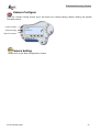
1
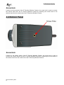
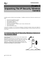
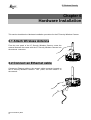
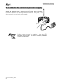
NetCamera
IP Security Wireless Camera
A02-IPCAM-W54
User Manual
A02-IPCAM-W54_ME01
Where solutions begin
Company certified ISO 9001:2000
IP Wireless Security Camera
IP Wireless Security Camera
Copyright
The Atlantis Land logo is a registered trademark of Atlantis Land SpA. All other names
mentioned mat be trademarks or registered trademarks of their respective owners. Subject to
change without notice. No liability for technical errors and/or omissions.
CE Mark Warning
This is a Class B product. In a domestic environment, this product may cause radio interference,
in which case the user may be required to take adequate measures.
Important Note
The antenna(s) used for this equipment must be installed to provide a separation distance of at
least 30 cm from all persons.
This equipment must not be operated in conjunction with any other antenna.
FCC Warning
Warning: Changes or modifications to this unit not expressly approved by the party responsible
for compliance could void the user authority to operate the equipment.
This device complies with Part 15 of the FCC Rules. Operation is subject to the following two
conditions: (1) this device may not cause harmful interference, and (2) this device must accept
any interference received, including interference that may cause undesired operation.
The users manual or instruction manual for an intentional or unintentional radiator shall caution
the user that changes or modifications not expressly approved by the party responsible for
compliance could void the user’s authority to operate the equipment.
NOTE: This equipment has been tested and found to comply with the limits for a Class B digital
device, pursuant to Part 15 of the FCC Rules. These limits are designed to provide reasonable
protection against harmful interference in a residential installation. This equipment generates,
uses and can radiate radio frequency energy and, if not installed and used in accordance with
the instructions, may cause harmful interference to radio communications.
However, there is no guarantee that interference will not occur in a particular installation. If this
equipment does cause harmful interference to radio or television reception, which can be
determined by turning the equipment off and on, the user is encouraged to try to correct the
interference by one or more of the following measures:
•
•
•
•
Reorient or relocate the receiving antenna.
Increase the separation between the equipment and receiver.
Connect the equipment into an outlet on a circuit different from that to
receiver is needed.
Consult the dealer or an experienced radio/TV technician for help.
which
the
NOTE
THE MANUFACTURER IS NOT RESPONSIBLE FOR ANY RADIO OR TV INTERFERENCE
CAUSED BY UNAUTHORIZED MODIFICATIONS TO THIS EQUIPMENT SUCH
MODIFICATIONS COULD VOID THE USER’S AUTHORITY TO OPERATE THE EQUIPMENT.
IP Wireless Security
Camera
TABLE OF CONTENTS
CHAPTER 1...................................................................................................................................................................... 5
1.1 INTRODUCTION ........................................................................................................................................................ 5
CHAPTER 2...................................................................................................................................................................... 6
2.1 NETWORK: ............................................................................................................................................................... 6
2.2 WEB BROWSER: ...................................................................................................................................................... 6
2.3 IPVIEW SE APPLICATION:....................................................................................................................................... 6
CHAPTER 3...................................................................................................................................................................... 7
3.1 SIMPLE TO USE ....................................................................................................................................................... 7
3.2 SUPPORT VARIETY OF PLATFORMS ........................................................................................................................ 7
3.3 WEB CONFIGURATION ............................................................................................................................................. 7
3.4 REMOTE UTILITY ..................................................................................................................................................... 7
3.5 BROAD RANGE OF APPLICATIONS .......................................................................................................................... 7
CHAPTER 4...................................................................................................................................................................... 9
4.1 FRONT PANEL .......................................................................................................................................................... 9
Power LED ............................................................................................................................................................ 9
Link LED .............................................................................................................................................................. 10
4.2 REAR PANEL.......................................................................................................................................................... 10
Network Cable Connector ................................................................................................................................. 10
DC Power Connector ......................................................................................................................................... 11
Reset Button........................................................................................................................................................ 11
Antenna Connector ............................................................................................................................................ 11
4.3 TOP PANEL ............................................................................................................................................................ 11
Screw Hole .......................................................................................................................................................... 12
4.4 BOTTOM PANEL ..................................................................................................................................................... 12
Screw Hole .......................................................................................................................................................... 12
CHAPTER 5.................................................................................................................................................................... 13
5.1 CONNECTING THE IP SECURITY WIRELESS CAMERA TO THE CAMERA STAND ................................................... 13
CHAPTER 6.................................................................................................................................................................... 14
6.1 ATTACH WIRELESS ANTENNA ............................................................................................................................... 14
6.2 CONNECT AN ETHERNET CABLE ........................................................................................................................... 14
6.3 ATTACH THE EXTERNAL POWER SUPPLY .............................................................................................................. 15
CHAPTER 7.................................................................................................................................................................... 16
CHAPTER 8.................................................................................................................................................................... 17
8.1 WEB CONFIGURATION ........................................................................................................................................... 17
8.2 MAIN MENU IMAGE ................................................................................................................................................ 18
8.3 SYSTEM ADMINISTRATION ..................................................................................................................................... 19
8.3.1 Management ............................................................................................................................................. 19
8.3.2 Configuration ............................................................................................................................................... 1
8.3.3 Tools............................................................................................................................................................. 9
8.3.4 Help ............................................................................................................................................................ 11
8.4 VIEW IMAGE – ACTIVEX MODE ............................................................................................................................. 12
8.5 VIEW IMAGE – JAVA MODE ................................................................................................................................... 13
CHAPTER 9.................................................................................................................................................................... 14
9.1 APPLICATIONS ....................................................................................................................................................... 14
9.2 IP SECURITY WIRELESS CAMERA APPLICATION DIAGRAMS ................................................................................ 15
9.2.1 Home Applications: .................................................................................................................................. 15
9.2.2 SOHO Applications: ................................................................................................................................. 15
A02-IPCAM-W54_ME01
1
IP Wireless Security
Camera
CHAPTER 10 ................................................................................................................................................................. 16
10.1 INSTALLATION ...................................................................................................................................................... 16
CHAPTER 11 ................................................................................................................................................................. 19
11.1 IPVIEW SE .......................................................................................................................................................... 19
11.1.1 IPView SE control panel........................................................................................................................ 19
11.1.2.How to Add a Camera ........................................................................................................................... 20
11.1.3.How to Change Camera........................................................................................................................ 23
11.1.4 How to Connect / Disconnect the Image ............................................................................................ 24
11.1.5 How to Delete a Camera....................................................................................................................... 27
11.1.6 Extra Information .................................................................................................................................... 28
11.1.7 How to Adjust the Property Setting...................................................................................................... 29
11.1.8 How to Adjust the Recording Setting................................................................................................... 32
CHAPTER 12 ................................................................................................................................................................. 33
12.1 WIZARD SETUP ................................................................................................................................................... 33
12.2 HOW TO USE WIZARD SETUP ............................................................................................................................. 35
APPENDIX A.................................................................................................................................................................. 39
APPENDIX B.................................................................................................................................................................. 41
APPENDIX C.................................................................................................................................................................. 45
APPENDIX D.................................................................................................................................................................. 47
APPENDIX E .................................................................................................................................................................. 48
APPENDIX F .................................................................................................................................................................. 50
A02-IPCAM-W54_ME01
2
IP Wireless Security
Camera
A02-IPCAM-W54_ME01
3
IP Wireless Security
Camera
A02-IPCAM-W54_ME01
4
IP Wireless Security
Camera
Chapter 1
Introduction
1.1 Introduction
Thank you for purchasing the IP Security Wireless Camera, a camera device that can be
connected directly to an Ethernet or Fast Ethernet network and also supported by the wireless
transmission based on the IEEE 802.11b standard. Compared to the conventional PC Camera,
the IP Security Wireless Camera features a built-in CPU and web-based solutions that can provide
a cost-effective solution to transmit real-time high-quality video images and sounds for monitoring.
The IP Security Wireless Camera can be managed remotely, accessed and controlled from any
PC/Notebook over the Intranet or Internet via a web browser. The simple installation procedures
and web-based interface allow you to integrate it into your network easily. With comprehensive
applications supported, the IP Security Wireless Camera is your best solution for remote monitor,
high quality, and high performance video images.
A02-IPCAM-W54_ME01
5
IP Wireless Security
Camera
Chapter 2
System Requirement
2.1 Network:
Local Area Network:
10Base-T Ethernet or 100Base TX Fast Ethernet
Wireless Local Area Network:
IEEE 802.11b/g Wireless LAN
Recommended PC or Notebook to Access the IP Security Wireless Camera
2.2 Web Browser:
System requirement:
• CPU: Pentium III, 700 MHz or above
• Memory Size: 64 MB (128 MB recommended)
• VGA card resolution: 800x600 or above
• Internet Explorer 5.0 or above (ActiveX & JAVA Mode – Image View for Windows OS and
JAVA Mode – Image View for other OS)
• Netscape 6.0 or above (JAVA Mode – Image View)
2.3 IPView SE Application:
System requirement:
• Support OS: Win 98 SE, Win 2000, Win Me, Win XP
• System requirement for IPView SE:
• CPU: Pentium III, 700 MHz or above
• Memory Size: 128 MB (256 MB recommended)
• VGA card resolution: 800x600 or above
A02-IPCAM-W54_ME01
6
IP Wireless Security
Camera
Chapter 3
Features and Benefits
This section describes the features and benefits of the IP Security Wireless Camera.
3.1 Simple To Use
The IP Security Wireless Camera is a standalone system with built-in CPU requiring no special
hardware or software such as PC frame grabber cards. The IP Security Wireless Camera supports
both ActiveX mode (for Internet Explorer users) and Java mode (for Internet Explorer and
Netscape Navigator users). Therefore, all that is required is a web browser software such as
Internet Explorer 5.0 or above or Netscape 6.0 or above. Just plug and view the picture from your
IP Security Wireless Camera with a valid IP Address.
3.2 Support Variety of Platforms
The IP Security Wireless Camera supports TCP/IP networking, SMTP e-mail, HTTP and other
Internet related protocols, and can be utilized in a mixed operating system environment such as
Windows, Unix, and Mac. It can be integrated easily into other www/Intranet applications.
3.3 Web Configuration
Applying a standard web browser, the administrator can configure and manage the IP Security
Wireless Camera directly from its own web page via the Intranet or Internet. Up to 64 users name
and password are permitted with privilege setting controlled by the administrator.
3.4 Remote Utility
The powerful IPView SE application assigns the administrator with a pre-defined user ID and
password, allowing the administrator to modify the IP Security Wireless Camera settings from the
remote site via Intranet or Internet. When new firmware is available, you can also upgrade
remotely over the network for added convenience. Users are also allowed to monitor the image,
and take snapshots.
3.5 Broad Range of Applications
With today’s high-speed Internet services, the IP Security Wireless Camera can provide the ideal
solution for live video images over the Intranet and Internet for remote monitoring. The IP Security
Wireless Camera allows remote access from a web browser for live image viewing and allows
administrator to manage and control the IP Security Wireless Camera anywhere and any time in
the world. Apply the IP Security Wireless Camera to monitor various objects and places such as
homes, offices, banks, hospitals, child-care centers, amusement parks and other varieties of
A02-IPCAM-W54_ME01
7
IP Wireless Security
Camera
industrial and public monitoring. The IP Security Wireless Camera can also be used for intruder
detection; in addition, it can capture still images for archiving and many more applications.
A02-IPCAM-W54_ME01
8
IP Wireless Security
Camera
Chapter 4
Physical Description
This section describes the externally visible features of the IP Security Wireless Camera.
4.1 Front Panel
Power LED
The Power LED is positioned on the right side of the IP Security Wireless Camera’s lens while
facing the IP Security Wireless Camera.
A steady blue light confirms that the IP Security Wireless Camera is powered on.
A02-IPCAM-W54_ME01
9
IP Wireless Security
Camera
Link LED
The Link LED is positioned on the right side of the IP Security Wireless Camera’s lens while facing
the IP Security Wireless Camera. It is located right of the Power LED
A steady orange light confirms that the camera has good connection to LAN connectivity.
Dependent on the data traffic the LED will begin to flash to indicate that the IP Security Wireless
Camera is receiving/sending data from/to the network.
4.2 Rear Panel
Network Cable Connector
The IP Security Wireless Camera’s rear panel features an RJ-45 connector for connections to
10Base-T Ethernet cabling or 100Base-TX Fast Ethernet cabling (which should be Category 5
twisted-pair cable). The port supports the NWay protocol, allowing the IP Security Wireless
Camera to automatically detect or negotiate the transmission speed of the network.
A02-IPCAM-W54_ME01
10
IP Wireless Security
Camera
DC Power Connector
The DC power input connector is located on the IP Security Wireless Camera’s rear panel, and is
labeled DC 5V with a single jack socket to supply power to the IP Security Wireless Camera.
Power will be generated when the power supply is connected to a wall outlet.
Reset Button
Reset will be initiated when the reset button is pressed once, and Power LED begins to flash.
Factory Reset will be initiated when the reset button is pressed continuously for three seconds or
when Power LED begins to light up. Release the reset button and the Power LED will begin to
flash, indicating the IP Security Wireless Camera is changing to factory reset. When factory reset
is completed, the IP Security Wireless Camera will be set to default on channel 11 and ESS-ID is
set as “NULL String” (This default setting will let the IP Security Wireless Camera connect to ANY
access point on the infrastructure network). The IP address will also return to the default setting as
192.168.0.20.
Antenna Connector
There is the SMA type antenna connector located on the rear panel of the IP Security Wireless
Camera, providing connection for one high sensitivity antenna included in the package.
4.3 Top Panel
A02-IPCAM-W54_ME01
11
IP Wireless Security
Camera
Screw Hole
Located on the top panel of the IP Security Wireless Camera, the screw hole is used to connect
the camera stand onto the IP Security Wireless Camera by attaching the screw head on the
camera stand into the screw hole of the IP Security Wireless Camera.
4.4 Bottom Panel
Screw Hole
Located on the bottom panel of the IP Security Wireless Camera, the screw hole is used to
connect the camera stand onto the IP Security Wireless Camera by attaching the screw head on
the camera stand into the screw hole of the IP Security Wireless Camera.
A02-IPCAM-W54_ME01
12
IP Wireless Security
Camera
Chapter 5
Unpacking The IP Security Wireless
Camera
Carefully remove all items from the package. In addition to this User’s Guide, be certain that you
have:
•
•
•
•
•
•
•
One IP Security Wireless Camera
One External Wireless Antenna
One Installation CDRom
One Quick Installation Guide
One DC power adapter suitable for your country’s electric power
One Camera Stand
One RJ-45 Ethernet Cable
If any item is missing, or if you find any damage or mismatch, promptly contact your dealer for
assistance immediately. Also, keep the box and packing materials in case you need to ship the unit
in the future.
5.1 Connecting the IP Security Wireless Camera to
the Camera Stand
The IP Security Wireless Camera comes with a camera stand
(optional) with a
swivel ball screw head that can be attached to the IP Security
Wireless Camera's bottom screw hole. Attach the camera stand
to the IP Security Wireless Camera and station it for your
application. There are three holes located in the base of the
camera stand allowing the IP Security Wireless Camera to be
mounted on the ceiling or any wall securely.
A02-IPCAM-W54_ME01
13
IP Wireless Security
Camera
Chapter 6
Hardware Installation
This section describes the Hardware installation procedure for the IP Security Wireless Camera.
6.1 Attach Wireless Antenna
From the rear panel of the IP Security Wireless Camera, screw the
external Antenna that came with the IP Security Wireless Camera into
the antenna connector.
6.2 Connect an Ethernet cable
Connect an Ethernet cable to the network cable connector located on
the IP Security Wireless Camera’s rear panel, and then attach it to
the network.
A02-IPCAM-W54_ME01
14
IP Wireless Security
Camera
6.3 Attach the external power supply
Attach the external power supply to the DC power input connector
located on Wireless IP Security Wireless Camera’s rear panel, and
then connect it to your local power supply.
Confirm power source is supplied
from the LED
indicators label Power on the IP Security Wireless
Camera is illuminated.
A02-IPCAM-W54_ME01
15
IP Wireless Security
Camera
Chapter 7
Security
To ensure the highest security and prevent unauthorized usage of the IP Security Wireless
Camera the Administrator has the exclusive privilege to access the System Administration for
settings and control requirements to allow users the level of entry and authorize the privileges for
all users. The IP Security Wireless Camera supports multi-level password protection and access
to the IP Security Wireless Camera is strictly restricted to defined the user who has a "User Name"
and "User Password" that is assigned by the Administrator.
Administrator can release a public user name and password so when remote users access the IP
Security Wireless Camera they will have the right to view the image transmitted by the IP Security
Wireless Camera.
Since the default settings are Null String, it is highly recommended to set
the "Admin ID" and "Admin Password" when you are the first time to use
the IP Security Wireless Camera. Once the ID and Password are defined,
only the administrator has the access to management the IP Security
Wireless Camera. This procedure should be done as soon as possible
since the security features with the IP Security Wireless Camera will not be
enabled until the "Admin ID" and "Admin Password" is defined.
A02-IPCAM-W54_ME01
16
IP Wireless Security
Camera
Chapter 8
Software Installation
This section describes the Software installation procedure of the IP Security Wireless Camera for
Web Configuration and IPView SE application.
8.1 Web Configuration
The IP Security Wireless Camera must be configured through its built-in Web-based Configuration.
Extensive knowledge of LAN will be helpful in setting up the IP Security Wireless Camera
From the web browser, enter the default IP address to access the Welcome screen of the IP
Security Wireless Camera.
To configure your IP Security Wireless Camera, type
http://192.168.0.20 in the address box. The number is the default IP address of your IP Security
Wireless Camera. Then, press [Enter].
The PC’s IP address must correspond with the IP Security Wireless
Camera’s IP address in the same segment for the two devices to
communicate.
A02-IPCAM-W54_ME01
17
IP Wireless Security
Camera
8.2 Main Menu Image
After the default IP address is entered from the browser, the IP Security Wireless Camera
Welcome screen will appear with a still image. There will be three options to choose from to set-up
and view your IP Security Wireless Camera, including:
•
•
•
View Image – ActiveX Mode
View Image – Java Mode
System Administration
A02-IPCAM-W54_ME01
18
IP Wireless Security
Camera
8.3 System Administration
Click “System Administration” from the Welcome screen to access the settings required for the
IP Security Wireless Camera.
There will be several options in the System menu bar to choose from to set your IP Security
Wireless Camera, including:
•
•
•
•
Management
Configuration
Tools
Help
Click “Home” to return to
Welcome Screen
Once you have changed the settings in each option, click Save to store the
settings, or Cancel to abandon, or Refresh to reload the status. During the
configuration, whenever you click Home in the top menu bar will make you
return to the Welcome window.
8.3.1 Management
The Management window contains the information of your configuration. Click the items in the left
column to view your settings, including: System, Video, Wireless, Network, and User.
A02-IPCAM-W54_ME01
19
IP Wireless Security
Camera
System
Click the System item in the left column to display the device status of your camera.
Device Status: The information about the camera, including the Camera Name, Location, Model,
Firmware Version, MAC Address and IP Address, can be found in this field.
Ethernet Status: You can monitor the networking status in this field, including the Link (network
connection), Speed, and the Duplex mode.
Video
Click the Video item in the left column to display the video configuration of your camera.
Video Status: The video configuration about the camera, including the Video Resolution,
Compression Rate, Frame Rate, Frame Size and IP Address, can be found in this field.
A02-IPCAM-W54_ME01
20
IP Wireless Security
Camera
Wireless
Click the Wireless item in the left column to display the information of the wireless LAN.
Wireless Status: The items in this field display the information of the wireless LAN, such as the
Connection Mode (Infrastructure or Ad-Hoc), Link, SSID, Channel, Transmission Rate, and WEP
Encryption.
Network
Click the Network item in the left column to display the information of the LAN.
Network Status: The items in this field display the information of the LAN, such as the IP Address,
Subnet Mask, Default Gateway, Primary DNS Address, Secondary DNS Address, Dynamic DNS,
Secondary
HTTP
Port,
UpnP,
FTP
Server
Test
and
E-Mail
Test.
A02-IPCAM-W54_ME01
21
IP Wireless Security
Camera
User
Click the User item in the left column to display the user(s) information.
Active Users: The items in this field display the user(s) information, including the user(s) IP
address, Name, and DateTime.
A02-IPCAM-W54_ME01
22
IP Wireless Security Camera
8.3.2 Configuration
The Configuration window contains commands for settings that are required to input key details to
setup the camera for operation. Click Configuration in the top menu bar and the Configuration
System
Click the System item in the left column to setup the basic configuration of your camera.
-System Setting: In this field, you can configure the basic information of your camera.
•
•
•
Camera Name: This field is used to enter a descriptive name for the device. The default setting
for the Camera Name is IP Security Wireless Camera. The maximum length is 32 (printable
ASCII).
Location: This field is used to enter a descriptive name for the location used by the camera
(optional).
Admin: This field is used to enter the administrator name along with the password to access the
System Administration settings. Be sure to enter the password twice to confirm the details once
in the Admin Password field and again in the Confirm Password field. The default setting for
administrator is blank space (Null String), and you need to key in the administrator name with a
maximum length of 12 (printable ASCII) characters and enter the administrator password with a
maximum length of 8 (printable ASCII) characters. It is highly recommended to set the Admin ID
A02-IPCAM-W54_ME01
1
IP Wireless Security Camera
•
and Admin Password as soon as possible to enable security option for the Wireless Internet
Camera to function.
LED Control: This option allows user to setup the LED illumination as desired. This feature
provides the flexibility when surveillance activity is ON. There are three options as follows:
Normal
OFF
Dummy
Power - Steady On of the LED indicator.
Link - Steady On of the LED indicator. When
WLAN activity is present the LED indicator
will flash steadily.
Power - LED indicator is off. Link – LED
indicator is off.
Power - Steady On of the LED indicator.
Link - Steady On of the LED indicator with
random flashing.
The default setting for the LED control is at Normal. When you have configured the LED
control, the correct illumination will be set after 1 minute.
Video
Click the Video item in the left column to setup the image configuration of your camera.
-Video Setting: In this field, you can configure the basic information of your camera.
•
•
•
•
•
•
•
•
Video Resolution: Select the desired video resolution format, including 160x120,
320x240 (default) and 640x480.
Compression Rate: Select the desired compression rate with five levels from Very Low to
Very High. Higher video compression rate will generate more compact file size with less
video quality and viseversa. The default setting is Medium.
Frame Rate: Select the frame rate desired with default setting at Auto for optimal frame rate.
Brightness Control: Adjust the brightness level with default setting at 64.
Contrast Control: Adjust the contrast level with default setting at 64.
Saturation Control: Adjust the saturation with default setting at 64.
Light Frequency: Adjust the light frequency to suit your area of operation from the options either
50 Hz or 60 Hz (default).
A02-IPCAM-W54_ME01
2
IP Wireless Security Camera
Wireless
Click the Wireless item in the left column to setup the wireless LAN configuration of your camera.
-Wireless Interface
•
•
Connection Mode: Use this option to determine the type of wireless communication for your
camera. There are two choices of Infrastructure mode and Ad-Hoc mode. The default setting is
Infrastructure.
SSID: The SSID (Service Set Identifier) is the name assigned to the wireless network. It will autodetect and display the SSID of wireless network connected in this box (it displays default initially).
This default setting will let the camera connect to ANY access point under the infrastructure
network mode. To connect the camera to a specific access point on the network, please make
A02-IPCAM-W54_ME01
3
IP Wireless Security Camera
•
•
sure to set the SSID of the camera to correspond with the access point’s SSID for communication.
Type any string up to 32 characters long (spaces, symbols, and punctuation are not allowed) in
the Network Name box. To connect the camera to an Ad-Hoc wireless workgroup, make sure to
set the same wireless channel and SSID to match with the PC/Notebook’s configuration for direct
wireless communication.
Wireless Channel: This pull-down menu provides the wireless channel for communication. A
"channel" is a range of frequencies to be used in communication between the camera and
access point in Infrastructure mode, or the camera and PC/Notebook in Ad-Hoc mode. Select
the appropriate channel from the list provided depending on the regulatory region where the unit
is sold. The default setting is at channel 11.
Transmission Rate: Select the data transmit rate from this pull-down menu. The default setting
is Fully Automatic.
-WEP Encryption
•
WEP Encryption: Wireless network communications can be intercepted easily. WEP (Wired
Equivalent Privacy) is an encryption method specified by the IEEE 802.11g standard to make any
intercepted communications extremely difficult to interpret by unauthorized parties. The default
setting for this option is Disable.
•
WEP Key Format: To enable WEP Encryption, you should decide the encryption format first by
selecting the ASCII or HEX option, and then input the WEP key (in the following Key 1~4 box).
• Encrypt Data Transmissions Using: Use this pulldown menu to decide to use Key 1, 2, 3 or 4
for encryption).
- WAP-PSK
• Preshared Key: Please put a key (8-63 ASCII).
- Advanced Setting: In this field, you can setup more advanced configuration.
•
•
•
Beacon Interval: This option defines time interval between two images sent.
Preamble: A preamble is a signal used in wireless environment to synchronize the transmitting
timing including Synchronization and Start frame delimiter. Please NOTE that if you want to
change the Preamble type into Long or Short, please check the setting of access point.
Authentication Type: Open System communicates the key across the network. Shared Key
allows communication only with other devices with identical WEP settings. The default setting is
Both.
ASCII input format:
ASCII format causes each character you type to be interpreted as an eightbit value. All unaccented upper-and lower-case Western European
characters that can beinput through your keyboard's typing zone are valid.
To setup a 64-bit WEP key, input 5 ASCII characters. For example, ‘12345’.
To setup an 128-bit WEP key, input 13ASCII characters. For example,
‘1234567890123’. Thesecharacter counts result in bit counts of 40 and 104
respectively; the camera will automatically pad your input to a bit count of
64 or 128.
HEX input format:
Hex format causes each pair of characters you type to be interpreted as an
eight-bit value in hexadecimal (base 16) notation. Only the digits 0 through
9 and the letters A through F (in upper or lower case) are valid. To setup a
64-bit WEP key, input 10 HEX format. For example, ‘3132333435’, which is
the same with ASCII input ‘12345’. To setup an 128-bit WEP key, input 26
HEX format. For example, ‘31323334353637383930313233’, which is the
same with ASCII input ‘1234567890123’. These character counts result in
bit counts of 40 and 104, respectively; the Wireless Internet Camera will
automatically pad your input to a bit count of 64 or 128.
A02-IPCAM-W54_ME01
4
IP Wireless Security Camera
Network
Click the Network item in the left column to setup the LAN configuration of your camera.
-TCP/IP: The items in this field display the information of the wireless LAN, such as the Connection
Mode (Infrastructure or Ad-Hoc), Link, SSID, Channel, Transmission Rate, and WEP Encryption.
• IP Address Mode: This field provides your with three options to select the IP Address Mode: Fixed
IP – You can select this option and enter the IP address directly. The default settings are:
IP Address – 192.168.0.20
Subnet Mask – 255.255.255.0
Default Gateway – 0.0.0.0
Dynamic Address (DHCP) – If your network uses the DHCP server, select this option. According
to this setting, the camera will be assigned an IP address from the DHCP server automatically.
Every time when the camera starts up, please make sure that the DHCP server is set to assign a
static IP address to your camera.
PPPoE – If your application requires a direct connection from an ADSL modem through the
camera’s RJ-45 LAN port, click this option and enter the User ID and Password into the respective
boxes. (You should have an ISP PPPoE account.) The camera will get an IP address from the ISP
as starting up.
• DNS IP Address: DNS (Domain Name System) server is an Internet service that translates
domain names into IP addresses. Enter at least one DNS IP Address in this field.
• Dynamic DNS: The Dynamic DNS service allows you to alias a dynamic IP address to a static
hostname in any of the domains, allowing your computer to be more easily accessed from various
locations on the Internet.
• Second HTTP Port: The default port for communication is via port 80, and you can change it
according to your network configuration. Select Enable from the option and enter the desired port
number in the following box.
• UPnP: UPnP is the architecture for pervasive peer-to-peer network connectivity of intelligent
A02-IPCAM-W54_ME01
5
IP Wireless Security Camera
appliances, wireless devices, and PCs of all form factors. Check the Enable option to enable the
function of your camera.
User
Click the User item in the left column to add, edit and delete users for your camera.
-User Access Control:
• Access Control: The administrator has the authority to give permission for the privilege to control
the device to users by selecting Enable or Disable. The default setting is No.
-Define Users: Use this field to add or delete users for your camera.
• Add User: Enter the user name in this box, and enter the user’s password assigned by the
administrator. The maximum password length is 8 (printable ASCII). The administrator has the
authority to give permission for the privilege to control the Upload/E-mail Video control to the
users by selecting Yes or No to activate the Upload/E-mail Video. To add a new user’s name,
enter the necessary information first and click the Add button.
• Delete User: Select the user you want to delete from the pull-down menu, and then click the
Delete button.
• User List: This list displays the current users status of your camera.
DateTime
Click the DateTime item in the left column to setup time and date for your camera, providing correct
information for the remote users who might be thousands of miles away from the camera’s location.
- Date & Time: You can set up time and date manually or automatically by selecting the Synchronized
with Time Server option.
• Synchronized with Time Server: Select this option and the time will be based on GMT setting.
The time will be synchronized every 10 minutes. When selecting this option, you have to enter the
required information in the following fields: IP Address – Enter the IP Address of the Time Server
in this box. Protocol – Two options of NTP or Time are available for your selection to link with the
Time Server. The default setting is NTP. TimeZone – Select the time zone for the region from the
A02-IPCAM-W54_ME01
6
IP Wireless Security Camera
•
pull-down menu.
Set Manually: Select this option to set the time manually. The system administrator must enter
the date and time in the respective field manually.
Upload
Click the Upload item in the left column to setup configuration for FTP server, time schedule and manual
operation.
-FTP Server: This field contains the following six basic settings for your FTP server.
• Host Address: The IP Address of the target FTP server.
• Port Number: The standard port number for the FTP server is Port 21, and it’s also the default
setting. If
• the FTP server uses a specific port, please confirm the IT manager.
• User Name: Enter the user name in this field.
• Password: Enter the user password in this field to login the FTP server.
• Directory Path: Enter an existing folder name in this field, and the images will be uploaded to the
given folder.
• Passive Mode: This function depends on your FTP server. Please check with your IT manager if
the FTP server uses passive mode. The default setting is No.
-Time Schedule: Select the “Enable upload video to FTP server” option and enter the relevant
information, such as the schedule, video frequency and base file name.
• Schedule: You can 1.) Choose Always to always upload the video to FTP server, or 2.) Set the
Schedule to manage the uploading task. In the Schedule option, you can set the Day and Time
Period option.
• Video Frequency: There are two ways to set the video frequency: 1.) Set Auto/1/2/3 frames per
second, or 2.) Set the time in seconds for every frame.
• Base File Name: Enter the file name to make sure that the images could be saved as the base file
A02-IPCAM-W54_ME01
7
IP Wireless Security Camera
•
name.
File: Since you may not upload only one image to the FTP server, you can choose the filing rule,
including Overwrite, Date/Time Suffix, and set up the Sequence Number.
-Manual Operation: When you click the Upload Video button in view video screen, it will start to upload
the image. The setting refers to Base File Name and File information above.
E-mail
Click the E-mail item in the left column to setup configuration for E-mail account, time schedule and
manual operation settings.
- E-mail Account: This field contains the following six basic settings for your FTP server.
• SMTP Server Address: SMTP (Simple Mail Transfer Protocol) is a protocol for sending e-mail
messages between servers you need to input the mail server address in this field.
• Sender e-mail Address: Enter the e-mail address of the user who will send the e-mail.
• Receiver e-mail Address: Enter the e-mail address of the user who will receive the e-mail.
• User Name: Enter the user name in this field.
• Password: Enter the user password in this field to login receiver’s mail server.
-Time Schedule: Select the “Enable-mail video to e-mail account” option to set schedule to send e-mail.
Please refer to the instruction in “Upload” section. The Interval option is to define time interval between
two images sent.
-Manual Operation: When you click the E-mail Video button in view video screen, it will start to e-mail
image. The Interval option is to define time interval between two images sent.
A02-IPCAM-W54_ME01
8
IP Wireless Security Camera
8.3.3 Tools
The Tools window contains commands for restarting the camera. Click Tools in the top menu bar and
the Tools window will
E-mail Test
Click the E-mail Test item in the left column to test your e-mail account.
- Test E-mail Account: Click the Test button to test the e-mail account you provided.
Reset
the device off and on and saved settings are retained. If you do not want to reset the camera, exit this
window without clicking YES.
A02-IPCAM-W54_ME01
9
IP Wireless Security Camera
Factory Reset
Do you really want to factory reset this device? Click the YES button from this option, and you can
resume all factory default settings for the camera. If you do not want to restore the factory settings, exit
this window without clicking YES. Please NOTE that you have to configure the network settings again
after a Factory Reset.
Firmware Upgrade
When new firmware is available, you can upgrade it through this window. Click the Browse… button to
point to the firmware file, and then click Update to start upgrading.
Backup
Click the Backup item in the left column to backup the current configuration.
-Backup Device Configuration to File: Do you really want to backup the configuration to file? Click the
Backup button from this option, and you can save the current configuration to file.
-Restore Device Configuration from File: You can resume the device configuration from saved file in
the computer. Click the Browse… button to point to the file, and then click Restore to start restoring.
A02-IPCAM-W54_ME01
10
IP Wireless Security Camera
8.3.4 Help
The Help window provides the basic information of the camera. Click Help in the top menu bar and the
Help window will appear as below:
About
Displays the camera’s model name and version.
Once the configuration is completed, click Home to return to the Welcome screen and select the desired
View Video option either through ActiveX Mode or Java Mode as described in the next section.
A02-IPCAM-W54_ME01
11
IP Wireless Security Camera
8.4 View Image – ActiveX Mode
To view video images from the browser, click “View Image – ActiveX Mode” from the welcome screen
to access the video images from Internet Explorer as illustrated below:
Camera Name*
Date Time***
Camera Name* - The Camera name will be display when the Camera Name field is entered in the Web
Configuration setting under “System”
Date/Time***- The date/time of the video server will show the date and time that come from time server
or you set manually.
Please refer to the appendix on how to install ActiveX.
1. Install to the Web Server
2. Install to your Local PC
In the View Image – ActiveX Mode, you are allowed upload image and E-mail image options. Just click
the desired selection “ON” or “OFF” to utilize the options for each of the functions.
Administrator has the authority to set the email image functions through the
setting in the “E-mail” of System Administration menu bar.
The Administrator has the authority to allow the users to set the image upload
functions through the setting in the “Upload” of System Administration menu bar.
A02-IPCAM-W54_ME01
12
IP Wireless Security Camera
8.5 View Image – Java Mode
Click “View Image – Java Mode” from the Welcome screen to access the video images from the
Internet Explorer or Netscape browser as illustrated below:
Camera Name*
Date/Time***
Camera Name* - The Camera name will be display when the Camera Name field is entered in the Web
Configuration setting under “System”
Date/Time***- The date/time of the IP Security Wireless Camera will show the date and time that come
from time server or you set manually.
In the View Image –Java Mode, you are allowed upload image and E-mail image options. Just click the
desired selection “ON” or “OFF” to utilize the options for each of the functions.
Administrator has the authority to set the email image functions through the
setting in the “E-mail” of System Administration menu bar.
The Administrator has the authority to allow the users to set the image upload
functions through the setting in the “Upload” of System Administration menu bar.
A02-IPCAM-W54_ME01
13
IP Wireless Security Camera
Chapter 9
IP Security Wireless Camera
Application
The IP Security Wireless Camera can be applied in wide variety of applications. With the built-in CPU, it
can work as a standalone system that provides a web-based solution transmitting high quality video
images and sounds for monitoring purposes.
It can be managed remotely, accessed and controlled
from any PC desktop over the Intranet or Internet via a web browser. With the easy installation
procedure, real-time live images will be available. In addition, once the IP Security Wireless Camera is
installed coupled with the IPView SE application, you can further expand the scope of the IP Security
Wireless Camera.
The following section will provide the typical applications for the IP Security Wireless Camera along with
the IPView SE application, and also includes some basic knowledge to assist in the installation and
configuration of the IP Security Wireless Camera.
9.1 Applications
•
•
•
Monitoring of local and remote places and objects such as construction sites, hospitals,
amusement parks, schools and day-care centers through the use of a web browser.
Capture single frame images from the IPView SE application.
Configure the camera to upload image or send-mail messages with a single frame image.
A02-IPCAM-W54_ME01
14
IP Wireless Security Camera
9.2 IP Security
Diagrams
Wireless
Camera
Application
9.2.1 Home Applications:
SOHO
Internet Camera
SOHO Wireless
Internet Camera
9.2.2 SOHO Applications:
SOHO
A02-IPCAM-W54_ME01
15
IP Wireless Security Camera
Chapter 10
IPView SE Application
10.1 Installation
Insert the CD-ROM into the CD-ROM drive to initiate the auto-run program. Once completed, a menu
screen will appear as below:
To install the IPView SE application click the "IPView SE" button to activate the installation procedure
for the application program.
Once executed, you will be asked to select the desired language. Select the language you want and
click “OK” to continue.
A02-IPCAM-W54_ME01
16
IP Wireless Security Camera
The Welcome screen will appear as below. Click the “Next” button.
The License Agreement window will appear as below. Read the details carefully and click the “Yes”
button.
In the following window, you may click “Next” to accept the recommended destination location or click
“Browse” to select another location. After specifying the desired destination location, click “Next”.
A02-IPCAM-W54_ME01
17
IP Wireless Security Camera
The following window allows you to select the folder where the IPView SE application will be located,
click “Next” to continue.
Please wait until one of the following two dialog boxes to appear.
If the system has to restart, select “Yes, I want to restart my computer now” and click the “Finish” button
to complete the installation procedure.
Otherwise, you may simply click the “Finish” button to complete the installation procedure
After successfully installing the IPView SE, the application program for the IP Security Wireless Camera
is automatically installed to \Programs\Files directory.
To start running the IPView SE, click Start -> Programs -> IPView SE -> IPView SE.
A02-IPCAM-W54_ME01
18
IP Wireless Security Camera
Chapter 11
Getting Started
This section describes the operation of the IPView SE application with detailed procedures for using the
application.
11.1 IPView SE
IPView SE is responsible for the management of preview, configuration, and searching of each camera.
It is designed with a user-friendly interface for ease of control and navigation requirements as illustrated
below.
11.1.1 IPView SE control panel
Minimize
Exit
Play
Scan
About
Combine
System Config
•
•
•
•
•
•
Add Camera
Minimize: To minimize the control panel
Exit: To close IPView SE
Play: To play back the recorded file
Scan: To display for each camera one by one
Combine: To combine all display windows in one
About: To display the information of IPView SE
A02-IPCAM-W54_ME01
19
IP Wireless Security Camera
11.1.2.How to Add a Camera
Add Camera
Add Camera
To add a new camera, click the Add Camera button.
illustrated below.
An Add Camera dialog box will appear as
You must select the camera and click the “Add” button to add a new camera.
You can select the “Input IP” button, an Input IP dialog box will appear as illustrated below.
Enter the IP Address of the camera in the specified field and click the “Add” icon to add a new camera.
If you want to add a camera through the Internet, you must key in a physical IP
Address.
When the camera is installed behind Gateway and the Open Second Port of
camera/Port Forwarding of Gateway function is enabled, the Gateway IP address
has to be entered with the Port Number (as below: 61.45.67.89:8180 or
www.webserver.com:8180)
A02-IPCAM-W54_ME01
20
IP Wireless Security Camera
If you are unsure of the IP Address of the camera, you can click the “Browse” button, the Browse
Camera dialog box will appear with a blank screen as illustrated below.
You must select the camera and click the “Add” button to add a new camera.
If the Login Camera dialog box appears, make sure to enter the correct User Name and Password and
click the “OK” button. Then, the camera will be added into IPView SE in list format. If the User Name
and Password is entered incorrectly, the camera will not be added into IPView SE.
The above dialog box will appear only if administrator has already set up the User Name and Password
in the Web Configuration setting.
If you forget to highlight the camera you want to add, a dialog box will appear to notify you of the error.
Make sure to save any changes you have made to keep the information updated.
You are allowed to add only one camera at a time.
A02-IPCAM-W54_ME01
21
IP Wireless Security Camera
When the user add the IP Security Wireless Camera, four icons will appear, including: “Assign IP to
Camera”, “Connect/Disconnect”, “Erase”, “Extra Information”
Camera Config
Assign IP to Camera
Motion record
Schedule record
Connect / Disconnect
Erase
A02-IPCAM-W54_ME01
Manual record
Extra Information
22
IP Wireless Security Camera
11.1.3.How to Change Camera
Assign IP of New Camera
To change camera, click the “Assign IP of Camera” button. An Assign IP of Camera dialog box will
appear as illustrated below.
You must select the camera and click the “Add” button to add a new camera.
A02-IPCAM-W54_ME01
23
IP Wireless Security Camera
11.1.4 How to Connect / Disconnect the Image
Connect the Image
Click the “Connect/Disconnect” button and the preview screen will appear with the video image.
When a new camera is added, it IS connected. You can see the image right
away. If you click the “Connect/ Disconnect” button, it will be in disconnecting,
also, no image showed.
Minimize
Click to minimize the display screen of the IP Security Wireless Camera.
Maximize
Click to maximize the display screen of the IP Security Wireless Camera.
Close
Click to close the display screen of the IP Security Wireless Camera.
Always on top
Click to have the display screen always appear on the top of the window.
Wake up control panel
Click to open the control panel again when it is closed.
Color setting
Click to adjust color of the image.
View list
Click to check the event list of the IP Security Wireless Camera.
A02-IPCAM-W54_ME01
24
IP Wireless Security Camera
Snapshot
Click to snapshot a picture from the IP Security Wireless Camera.
Rotate image
Click to rotate the image of the IP Security Wireless Camera.
A02-IPCAM-W54_ME01
25
IP Wireless Security Camera
Disconnect the Image
Click the “Connect / Disconnect” button, the camera will be disconnected.
A02-IPCAM-W54_ME01
26
IP Wireless Security Camera
11.1.5 How to Delete a Camera
Erase Camera
To delete a camera, you must select the camera to delete from the IPView SE control panel. Then, click
the “Erase Camera” button.
After deleting the camera, the IPView SE control panel will appear as below.
A02-IPCAM-W54_ME01
27
IP Wireless Security Camera
11.1.6 Extra Information
Extra Information
The screen displays the camera’s information.
A02-IPCAM-W54_ME01
28
IP Wireless Security Camera
11.1.7 How to Adjust the Property Setting
System Configure
From the control panel, select the button and the dialog box will appear as shown below.
Log Storage:
1. Single HDD Reserve Space
This option permits reserved HDD space from 500 MB to 1000 MB.
2. Split Recording File
From this option, you can adjust the file size for recording the video images (the default setting is
10MB). If the recorded video files reach the file size, video images will be recorded into another file
automatically.
By File Size - permits recording by file size from 10 MB to 50 MB.
3. Storage List
This option is used to define the path to save image files.
The software will create a camera name folder as the “Storage List” which is allowed to create up to
16 File Path.
Recycle:
When you enabled this function, it will recycle the HDD space once the disk space is less than the size
defined. The size defined can be from 200 MB to 50000 MB.
Proxy Server:
Select this option to enable the Proxy Server support.
Camera Scan Delay:
It allows you to display for each camera one by one. The time interval for each camera can be from 1
Sec. to 20 Sec.
A02-IPCAM-W54_ME01
29
IP Wireless Security Camera
Camera Configure
Click the “Camera Config” button and it will active the Camera Setting, Motion Setting and Update
Firmware buttons.
Camera Setting
Motion Setting
Update Firmware
Camera Setting
Please refer to the “Web Configuration” section.
A02-IPCAM-W54_ME01
30
IP Wireless Security Camera
Motion Setting
You can adjust the sensitivity level and choose the Invoke Alarm options to work with motion detection
function.
Besides the Alarm Beep, Send Email can be enabled when motion detected.
The user can define the time interval to Send E-mail.
•
•
•
•
•
•
•
Mail Server: Mail Server IP or name.
Mail From: E-Mail Address of sender.
Mail To: E-Mail Address of receiver.
Subject: Can be any information to high light the message.
User Name: Enter the user name in this field.
Password: Enter the user password in this field to login receiver’s mail server
Interval Time: The time interval to send next E-Mail the unit is by second.
A02-IPCAM-W54_ME01
31
IP Wireless Security Camera
Update Firmware
Enter the File Path and click the “Update” button, the firmware will be updated automatically.
If you are unsure of the File path, you can click the “Browse” button, the Browse dialog box will appear
as illustrated below.
During firmware update process, please make sure no interruptions will occur as
it might possibly cause serious damage to the IP Security Wireless Camera
11.1.8 How to Adjust the Recording Setting
There are three ways to start recording image - Motion Record, Schedule Record & Manual Record.
Motion Record
This option allows the camera to trigger recording by motion detected. You can adjust the sensitivity
level and choose the warning options when motion is detected from motion setting.
Schedule Record
This option allows the camera to trigger recording as schedule defined. The schedule is set by date or
week day.
Manual Record
This option allows the camera to trigger recording manually.
A02-IPCAM-W54_ME01
32
IP Wireless Security Camera
Chapter 12
Setup Wizard
12.1 Wizard Setup
The Setup Wizard is a convenient tool that will guide you through the installation of your camera easily
and quickly. After connecting the camera to your computer, you can install the Setup Wizard and
complete the configuration now.
Insert the CD-ROM into the CD-ROM drive to initiate the auto-run program. Once completed, a menu
screen will appear as below:
To install the IPView SE application click the "Install Wizard" button to activate the installation
procedure for the application program.
A02-IPCAM-W54_ME01
33
IP Wireless Security Camera
Once executed, you will be asked to select the desired language. Select the language you want and
click “OK” to continue.
The Welcome screen will appear as below. Click the “Next” button.
The License Agreement window will appear as below. Read the details carefully and click the “Yes”
button.
In the following window, you may click “Next” to accept the recommended destination location or click
“Browse” to select another location. After specifying the desired destination location, click “Next”.
The following window allows you to select the folder where the IPView SE application will be located,
click “Next” to continue.
Please wait until one of the following two dialog boxes to appear.
Otherwise, you may simply click the “Finish” button to complete the installation procedure
A02-IPCAM-W54_ME01
34
IP Wireless Security Camera
After successfully installing theWizard, the application program for the IP Security Wireless Camera is
automatically installed to \Programs\Files directory.
12.2 How to use Wizard Setup
To run the Setup Wizard, click Start -> Programs -> Setup Wizard.
When you launch the Setup Wizard, the main window will appear as shown, and the connected camera
will be displayed in the list.
Control buttons
The components on the Setup Wizard:
Click Wizard to begin configuring the selected camera.
Click Research allows you to search the connected camera again.
Click Link to launch the web browser and view the images.
A02-IPCAM-W54_ME01
35
IP Wireless Security Camera
Click About to show the general information of the selected camera.
Click Exit to close the Setup Wizard.
Changing the Admin ID and Password
By default settings, the Admin ID and Password are blank. For security purpose, you are
recommended to change the Admin ID and Password immediately.
Click Wizard. The dialog box as shown appears,
asking you to enter the Admin ID and Password.
Click OK.
If required, select the Change options and enter the new
Admin ID and Password.
Click Next.
The settings of IP Address, Subnet Mask and Default
Gateway must correspond with your camera and
networking settings. Please check with your network
administrator for correct settings.
Click Next.
A02-IPCAM-W54_ME01
36
IP Wireless Security Camera
The Connection Mode depends on how your camera
is connected to your network. Click Infrastructure for
use with a router or Adhoc for peer-to- peer. The
Network Name, Wireless Channel, and Encryption
Key MUST correspond with your wireless network
settings.
This window displays the settings you set up. For
any change, click Back to modify your settings.
Otherwise, click Restart to save and apply the
settings.
The configuration is completed, and you will return
to the main window. Click Link to launch the web
browser and view the images.
A02-IPCAM-W54_ME01
37
IP Wireless Security Camera
Software Information
Click About to show the general
information of the selected camera.
Click OK to return to the main window.
A02-IPCAM-W54_ME01
38
IP Wireless Security Camera
Appendix A
Frequently Asked Questions
Question
Answer
What is an IP Security The IP Security Wireless Camera is a standalone system
Wireless Camera?
connecting directly to an Ethernet or Fast Ethernet network
and supported by the wireless transmission based on the
IEEE 802.11b standard. It is different from the conventional
PC Camera, the IP Security Wireless Camera is an all-in-one
system with built-in CPU and web-based solutions providing a
low cost solution that can transmit high quality video images
for monitoring. The IP Security Wireless Camera can be
managed remotely, accessed and controlled from any
PC/Notebook over the Intranet or Internet via a web browser.
Question
Answer
What is the maximum
number of users that
can be allowed to
access the IP Security
Wireless
Camera
simultaneously?
Maximum number of users that can log onto the IP Security
Wireless Camera at the same time is 64. Please keep in
mind the overall performance of the transmission speed will
slow down when many users are logged on.
Question
Answer
What algorithm is used The IP Security Wireless Camera utilizes the JPEG image
to compress the digital compression technology providing high quality images for
image?
users. JPEG is adopted since it is a standard for image
compression and can be applied to various web browser and
application software without the need to install extra software.
Question
Answer
Can I change the
wireless
antenna
attached to the IP
Security
Wireless
Camera?
The wireless antenna can be changed for a variety of reasons
such as extending the wireless transmission range, however,
please consult authorized distributors before attempting as
the connectors must be SMA connector type.
A02-IPCAM-W54_ME01
39
IP Wireless Security Camera
Question
Answer
What is the wireless
transmission range for
the IP Security Wireless
Camera?
Generally the wireless distance can go up to 100 meters
indoors and up to 300 meters outdoors. The range is
limited by the number of walls, ceilings, or other objects
that the wireless signals must pass through. Typical
ranges vary depends on the types of materials and
background Radio Frequency (RF) noise in your home
or business and the configuration setting of your network
environment.
Question
Answer
Can the IP Security The IP Security Wireless Camera is not weatherproof. It
Wireless Camera be needs to be equipped with a weatherproof case to be used
used out-doors?
outdoors and it is not recommended.
Question
Answer
What network cabling is The IP Security Wireless Camera uses Category 5 UTP cable
required for the IP allowing 10 Base-T and 100 Base-T networking
Security
Wireless
Camera?
Question
Answer
Can the IP Security No, the IP Security Wireless Camera is an IP Security
Wireless Camera be Wireless Camera used only on Ethernet and Fast Ethernet
setup as a PC-cam on network and supported by wireless transmission.
the computer?
Question
Answer
Can the IP Security The IP Security Wireless Camera can be connected to LAN
Wireless Camera be with private IP addresses.
connected
on
the
network if it consists of
only
private
IP
addresses?
Question
Answer
Can the IP Security
Wireless Camera be
installed and work if a
firewall exists on the
network?
If a firewall exists on the network, port 80 is open for ordinary
data communication.
However, since the IP Security
Wireless Camera transmits image data, the default port 8481
is also required. Therefore, it is necessary to open port 8481
of the network for remote users to access the IP Security
Wireless Camera.
A02-IPCAM-W54_ME01
40
IP Wireless Security Camera
Appendix B
Trouble Shooting
Question
Answer
I cannot access the IP
Security
Wireless
Camera from a web
browser.
The possible cause might be the IP Address for the IP
Security Wireless Camera is already being used by another
device. To correct the possible problem, you need to first
disconnect the IP Security Wireless Camera from the
network. Then run the PING utility (follow the instructions in
Appendix B - PING Your IP Address).
Question
Answer
I cannot access the IP
Security
Wireless
Camera from a web
browser.
Another possible reason is the IP Address is located on a
different subnet. To fix the problem, run the PING utility
(follow the instructions in Appendix B - PING Your IP
Address). If the utility returns “no response” or similar, the
finding is probably correct, then you should proceed as
follows:In Windows 95/98/2000 and Windows NT, double check the
IP Address of the IP Security Wireless Camera is within the
same subnet as your workstation.
Click “Start”, “Setting”, “Control Panel”, and the “Network”
icon.
Select TCP/IP from the “Network” dialog box and from the
“TCP/IP Properties” dialog box click “Specify an IP address”.
If the IP Security Wireless Camera is situated on a different
subnet than your workstation, you will not be able to set the
IP address from this workstation. To verify make sure the
first 3 sections of the IP address of the IP Security Wireless
Camera corresponds to the first 3 sections of the workstation.
Therefore the IP address of the IP Security Wireless Camera
must be set from a workstation on the same subnet.
Question
A02-IPCAM-W54_ME01
Answer
41
IP Wireless Security Camera
I cannot access the IP
Security
Wireless
Camera from a web
browser.
Other possible problems might be due to the network cable.
Try replacing your network cable. Test the network interface
of the product by connecting a local computer to the unit,
utilizing a standard Crossover (hub to hub) Cable. If the
problem is not solved the IP Security Wireless Camera might
be faulty.
Question
Answer
Why does the Power The power supply used might be at fault. Confirm that you
LED not light up are using the provided power supply DC 5V for the IP
constantly?
Security Wireless Camera and verify that the power supply is
well connected.
Question
Why does the Link LED
not light up properly?
Question
Why does the IP
Security
Wireless
Camera work locally
but not externally?
A02-IPCAM-W54_ME01
Answer
•
There might be a problem with the network cable. To
confirm that the cables are working, PING the address
of a know device on the network. If the cabling is OK
and your network is reachable, you should receive a
reply similar to the following (…bytes = 32 time = 2
ms).
•
The network device utilized by the IP Security
Wireless Camera is not functioning properly such as
hubs or switches. Confirm the power for the devices
are well connected and functioning.
•
The wireless connection might be at fault. In ad-hoc
mode make sure the IP Security Wireless Camera
wireless channel and ESS-ID is set to match the
PC/Notebook wireless channel and ESS-ID for direct
communication. Under infrastructure mode make
sure the ESS-ID on the PC/Notebook and the IP
Security Wireless Camera must match with the
Access Point’s ESS-ID.
Answer
•
Might be caused from the firewall protection. Need to
check the Internet firewall with your system
administrator.
•
The default router setting might be a possible reason.
Need to double check if the configuration of the
default router settings is required.
42
IP Wireless Security Camera
Question
Answer
Why does a series of
broad vertical white line
appears through out
the image?
A likely issue is that the CMOS sensor becomes overloaded
when the light source is too bright such as direct exposure to
sunlight or halogen light. You need to reposition the IP
Security Wireless Camera into a more shaded area
immediately as this will damage the CMOS sensor.
Question
Answer
There is bad focus on
the IP Security Wireless
Camera, what should
be done?
Question
Noisy images occur
how can I solve the
problem?
•
The focus might not be correctly adjusted for the line
of sight. You need to adjust the IP Security Wireless
Camera focus manually as described in Adjust IP
Security Wireless Camera Focus.
•
There is no adaptor fitted with your C-type lens. If you
have previously changed the supplied CS-type lens,
you may have unintentionally installed a C-type lens
without fitting the adaptor first.
Answer
•
•
Question
There is poor image
quality, how can I
improve the image?
A02-IPCAM-W54_ME01
The video images might be noisy if the IP Security
Wireless Camera is used is a very low light
environment. To solve this issue you need more
lighting.
There might be wireless transmission interference
make sure there are no other wireless devices on the
network that will affect the wireless transmission.
Answer
•
A probable cause might be the incorrect display
properties configuration for your desktop. You need
to open the Display Properties on your desktop and
configure your display to show at least 65’000 colors
for example at least 16-bit.
•
Applying only 16 or 256 colors on your computer will
produce dithering artifacts in the image.
•
The configuration on the IP Security Wireless Camera
image display is incorrect.
Through the Web
Configuration Image section you need to adjust the
image related parameter for improve images such as
brightness, contrast, hue and light frequency. Please
refer to the Web Configuration section for detail
information.
43
IP Wireless Security Camera
Question
Noisy images occur
how can I solve the
problem?
Answer
•
•
Question
The video images might be noisy if the IP Security
Wireless Camera is used is a very low light
environment. To solve this issue you need more
lighting.
There might be wireless transmission interference
make sure there are no other wireless devices on the
network that will affect the wireless transmission.
Answer
There are no images The ActiveX might be disabled. If you are viewing the images
available through the from Internet Explorer make sure ActiveX has been enabled
web browser?
in the Internet Options menu. Alternatively, you can use the
Java Applet for viewing the required images.
A02-IPCAM-W54_ME01
44
IP Wireless Security Camera
Appendix C
Xplug Control Installation
Installation To Web Server
It is highly recommended to install the Xplug Control application to the Web
Server for IE 5.0. It must be installed to a Public Domain with Fixed IP address.
1. Installation:
Copy the “xplug.ocx” file to any WEB Server table.
2. Setting (Configuration):
From the Web Configuration menu select “System” and under the “Loading ActiveX From” input
web server location
(http://www.web server location.com/).
Once the settings are completed, the user now is able to access the IP Security Wireless Camera from
the web browser by selecting the image view – ActiveX mode.
Installation To Local PC
Insert the CD-ROM into the CD-ROM drive to initiate the auto-run program. Once completed, a menu
screen will appear as below:
To install Xplug Control, click the "Xplug Control" button to activate the installation procedure for the
plug-in program.
Once executed, a prompt will appear requesting the input of the desired language selection. Make the
desired selection and click “OK” to continue.
The Welcome screen will appear. Click the “Next” button to proceed with the installation.
A02-IPCAM-W54_ME01
45
IP Wireless Security Camera
The License Agreement prompt will appear as below. Read the details carefully and click the “Yes”
button to continue with the installation procedure.
Click the “Finish” button to complete Setup of the Xplug Control Utility program for the IP Security
Wireless Camera.
A02-IPCAM-W54_ME01
46
IP Wireless Security Camera
Appendix D
Adjust IP Security Wireless Camera
Focus
To adjust the focus of the lens, you need to turn the lens slowly in either clockwise or anti-clockwise
direction until the desired image appears. DO NOT over turn the lens in either of the directions as it will
be out of focus.
You can further adjust the IP Security Wireless Camera's image quality through
System Administration – Image of Web Configuration. Please refer to Web
Configuration section for further details.
Direct exposure to sunlight may cause permanent damage to the CMOS sensor.
Therefore do not expose the IP Security Wireless Camera’s lens directly to
sunlight.
When operation is required in glaring light environment, it is
recommended to use an iris lens.
The IP Security Wireless Camera is designed for indoor usage and if your
application requires prolong exposure to sunlight, a sun visor is recommended to
protect the IP Security Wireless Camera.
A02-IPCAM-W54_ME01
47
IP Wireless Security Camera
Appendix E
Specification
Video specification:
Resolution:
Sensor:
Gain control:
Exposure:
White Balance:
Focal Length:
Aperture:
Focus Extent:
Lens mounting:
640 x 480 pixel
color CMOS sensor
Automatic
Automatic
Automatic
6.0 mm
F=1.8
20 cm - ∞
Fixed board lens
Image (Video Setting)
Image compression:
JPEG
Frame rate:
QCIF@30fps,25fps@CIF, 10fps@VGA
Compression Rate selection: 5 levels, very low, low, middle, high, very high
Frame rate setting:
1, 5, 7, 15, 20, auto (depends on the video format)
Video resolution:
160x120, 320x240, 640x480
Brightness control:
Range 1- 128
Contrast control:
Range 1- 128
Saturation Control:
Yes
Digital Zoom
Yes(4X)
Upside down and Mirror
Yes
Hardware Interface
LAN Connector:
Wireless LAN:
LED Indicator:
One RJ-45 port to connect to 10/100Mbps Ethernet, auto-sensed
Built-in 802.11g (Wi-Fi compliant) wireless LAN module
Power LED (Blue), Link LED (Orange)
Power Supply:
Power Communication:
Antenna Connector:
DC 5V, switching type
5 Watt (1000mA x 5V)
1 connectors (Reverse-SMA)
Communication Support
Communication:
Encryption:
Communication protocol:
10/100Mbps Ethernet and 802.11g wireless LAN.
WAP-PSK, WEP 128 bit, WEP 64 bit or OFF
HTTP, FTP, TCP/IP, UDP, ARP, ICMP, BOOTP, DHCP, PPPoE
System
CPU
RAM
Flash ROM
OS
A02-IPCAM-W54_ME01
RDC R2880
8M Byte
2M Byte
RTOS
48
IP Wireless Security Camera
Browser Support
System requirement:
CPU:
Pentium III, 700 MHz or above
Memory Size:
64 MB (128 MB recommended)
VGA card resolution: 800x600 or above
Internet Explorer 5.0 or above (ActiveX Mode –View Image supports Internet Explorer under Windows
OS)
Netscape 6.0 or above
IPView SE Application
Support OS: Win 98 SE, Win 2000, Win Me, Win XP
System requirement for IPView:
CPU:
Pentium III, 700 MHz or above
Memory Size:
128 MB (256 MB recommended)
VGA card resolution: 800x600 or above
Powerful application software for image capture and video recording
• Multiple Video Window Simultaneously
• Motion Detection with alert and E-mail sending.
• Recording triggered by Motion Detection, Schedule, and Manual.
• Single Frame Image Snap shot
Operating environment
Operating temperature:
Storage temperature:
Humidity:
5°C ~ 40°C
-25°C ~ 50°C
5% ~ 95% non-condensing
Package Contents:
One IP Security Wireless Camera
One Quick Installation Guide
One External Antenna (2.2 dBi)
One Installation CDRom with IPView SE
One Camera Stand
One DC Power Adapter
One RJ-45 Ethernet Cable
A02-IPCAM-W54_ME01
49
IP Wireless Security Camera
APPENDIX F
Support
If you have any problems with the IP Security Wireless Camera, please consult this manual.
If you have any other questions you can contact the Atlantis Land company directly at the
following address:
Atlantis Land SpA
Viale De Gasperi, 122
20017 Mazzo di Rho(MI)
Tel: +39. 02.93906085, +39. 02.93907634(help desk)
Fax: +39. 02.93906161
Email: [email protected] or [email protected]
WWW: http://www.atlantis-land.com
A02-IPCAM-W54_ME01
50