1
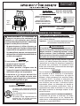
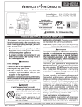
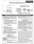
INSTALLATION &
OWNER’S MANUAL
Vented Series: 015, 017, 073, 818, 868
Unvented Series: 115, 117, 173, 118, 168
Complies with:
ANSI Z21.97/CSA 2.41 for
outdoor decorative gas
appliances
(when installed with select
R.H.P. Vented/Unvented
Gas Appliances)
017
series
shown
F14-023
WARNING: For Outdoor Use Only
PHOENIX & MARIPOSA OUTDOOR FIREPLACES
INSTALLER & CONSUMER: These instructions MUST
be retained with this unit for future reference.
WARNING: If the information in this manual
is not followed exactly, a fire or explosion may
result causing property damage, personal
injury or loss of life.
Important: Read these instructions carefully
before starting installation of the unit.
- Do not store or use gasoline or other
flammable vapors and liquids in the vicinity
of this or any other appliance.
WARNING
Improper installation, adjustment, alteration,
service, or maintenance can cause property
damage, personal injury, or loss of life. Read
the installation, operating and maintenance
instructions thoroughly before installing or
servicing this equipment.
- A propane cylinder not connected for use
shall not be stored in the vicinity of this or
any other appliance.
DANGER
The R.H.P. gas appliance is designed as an
attended appliance. Adults must be present when
the unit is operating. DO NOT leave the unit burning
when unattended. If the product is left burning
unattended, it may cause damage or serious injury.
IMPORTANT
For safe operation and proper performance of
this product and to comply with certification,
listings, and building code acceptances, use ONLY
Robert H. Peterson (R.H.P.) controls, parts, and
accessories that have been specifically listed or
certified for use with this fireplace. Use of other
controls, parts, or accessories is prohibited and
will void all warranties, certifications, listings, and
building code approvals, and may cause property
damage, personal injury, and loss of life.
If you smell gas:
1. Shut off gas to the appliance.
2. Extinguish any open flame.
3. If odor continues, keep away from the
appliance and immediately call your gas
supplier or fire department.
Installation and service must be performed by
an NFI Certified or other qualified professional
installer, service agency, or gas supplier.
DANGER
CARBON MONOXIDE HAZARD
A vented gas appliance can produce
carbon monoxide which has no odor.
Using it in an enclosed space can
kill you.
Never use the appliance in an
enclosed space such as a camper,
tent, car, or home.
CODE AND SUPPLY REQUIREMENTS:
The gas installation must conform with local codes
and ordinances, or, in the absence of local codes,
with the latest National Fuel Gas Code, ANSI Z223.1.
Robert H. Peterson Co. • 14724 East Proctor Avenue • City of Industry, CA 91746
REV 0 - 1405141300
1
L-H2-011
INSTALLATION ET
MODE D'EMPLOI
Ventilé Série:
015, 017, 073, 818, 868
Non Ventilé Série: 115, 117, 173, 118, 168
Conforme à:
ANSI Z21.97/CSA 2.41 pour
l'extérieur des appareils à gaz
décoratifs
(lorsqu'il est installé avec
sélection R.H.P. Ventilé / non
ventilé les appareils à gaz)
Série
017
montré
F14-023
AVERTISSEMENT: Pour l'usage extérieur
seulement
PHOENIX & MARIPOSA CHEMINÉES D'EXTÉRIEUR
d'INSTALLATEUR; CONSOMMATEUR: Ces
instructions DOIVENT être maintenues avec cet appareil
pour la future référence.
Important: Lisez ces instructions soigneusement avant
de commencer l'installation de l'unité.
AVERTISSEMENT: Si l'information en
ce manuel n'est pas suivie exactement, une
incendie ou une explosion peut résulter
entraînant des dégats matériels, le dommage
corporel ou des pertes humaines.
- Ne pas entreposer ni utiliser d'essence ou
d'autres vapeurs et liquides inflammables
à proximité de cet appareil ou de tout autre.
AVERTISSEMENT
L'installation, l'ajustement, le changement, le
service, ou l'entretien inexact peuvent causer des
dégats matériels, le dommage corporel, ou des
pertes humaines. Lisez l'installation, l'opération
et les instructions d'entretien complètement avant
d'installer ou entretenir cet équipement.
- Une bouteille de propane non branchée ne
doit pas être entreposée à proximité de cet
ou tout autre appareil.
DANGER
Le R.H.P. Appareil à gaz est conçu comme un appareil
assisté. Les adultes doivent être présents lorsque
l'appareil est en marche. Ne laissez pas l'appareil est
en marche sans surveillance. Si le produit est laissé
brûler sans surveillance, il peut causer des dommages
ou des blessures graves.
IMPORTANT
Pour un fonctionnement sûr et une bonne performance
de ce produit et de se conformer à la certification,
les annonces, et les acceptations du code du
bâtiment, utiliser uniquement des contrôles Robert
H. Peterson (R.H.P.), les pièces et accessoires qui
ont été spécifiquement énumérés ou certifiées pour
une utilisation avec ce foyer. L'utilisation d'autres
commandes, pièces, ou accessoires est interdite et
videra toutes les garanties, certifications, listes, et
approbations de codes du bâtiment, et peut causer
des dégats matériels, le dommage corporel, et des
pertes humaines.
Si vous sentez une odeur de gaz:
1. Coupez le gaz à l'appareil.
2. Éteindre toute flamme nue.
3. Si l'odeur persiste, éloignez-vous de
l'appareil et appelez immédiatement votre
fournisseur de gaz ou les pompiers.
L'installation et le service doivent être
assurés par un NFI certifié ou toute autre
installateur, agence de service, ou fournisseur
professionnelle qualifiée de gaz.
DANGER
CARBON MONOXIDE HAZARD
Un foyer à gaz ventilé peut produire
du monoxyde de carbone qui n'a pas
d'odeur.
Son utilisation dans un espace clos
peut vous tuer.
Ne jamais utiliser l'appareil dans un
espace clos, tel qu'une caravane,
tente, voiture ou à la maison.
REV 0 - 1405141300
CONDITIONS DE CODE ET D'APPROVISIONNEMENT:
L'installation de gaz doit se conformer aux codes
locaux et aux ordonnances, ou, en l'absence des
codes locaux, au plus défunt code national de gaz de
carburant, la norme ANSI Z223.1.
2
L-H2-011
TABLE OF CONTENTS
GETTING STARTED
PRE-INSTALLATION AND PREPARATION SAFETY GUIDELINES .....................................................4
INSTALLATION SAFETY GUIDELINES ...................................................................................................5
OPERATING THE UNIT SAFELY AND CORRECTLY .............................................................................5
SAFE USE & MAINTENANCE OF PROPANE GAS CYLINDERS ..........................................................7
SPECIFICATIONS AND DIMENSIONS......................................................................................................8
MINIMUM CLEARANCES TO COMBUSTIBLES ..................................................................................11
PARTS LIST ................................................................................................................................................ 12
INSTALLATION
IMPORTANT SAFETY INFORMATION .................................................................................................. 15
FIREPLACE INSTALLATION .................................................................................................................. 15
BEFORE YOU BEGIN ........................................................................................................................... 15
LOCATION .......................................................................................................................................... 15
FIREPLACE ASSEMBLY - OVERVIEW ................................................................................................... 16
FIREPLACE ASSEMBLY - STEP BY STEP .............................................................................................. 17
BURNER INSTALLATION ....................................................................................................................... 21
BURNER INSTALLATION GUIDELINES ................................................................................................ 21
LEAK TEST ........................................................................................................................................... 21
OPTIONAL ACCESSORIES ...................................................................................................................... 22
OPTIONAL GFRC CHIMNEY RAIN VENT CAP ...................................................................................... 22
OPTIONAL SCROLL SCREEN ............................................................................................................... 22
OPTIONAL GFRC PROTECTOR PLATE ................................................................................................ 22
USE, CARE, & SERVICE
LIGHTING GUIDELINES ......................................................................................................................... 23
FOR YOUR SAFETY, READ BEFORE LIGHTING ................................................................................... 23
TO LIGHT THE APPLIANCE ................................................................................................................. 23
TO SHUT OFF GAS TO THE APPLIANCE ............................................................................................. 23
SERVICING AND CLEANING ................................................................................................................. 25
ANNUAL CLEAN / INSPECTION GUIDELINES ..................................................................................... 25
TROUBLESHOOTING .............................................................................................................................. 25
WARRANTY .............................................................................................................................................. 26
IMPORTANT SAFETY INFORMATION
Congratulations on your purchase of an American Fyre Designs outdoor gas fireplace. Made with pride in America,
your new fireplace complies with national safety standards and when installed per these instructions and used
as intended it will provide warmth and comfort to your outdoor area for many years.
Prior to installation and operation ensure that all specifications, dimensions, and minimum clearances
stated in this manual are observed. You must read all warnings and safety information, and understand
all of the information in this manual. All installation requirements must be observed and met.
REV 0 - 1405141300
3
L-H2-011
PRE-INSTALLATION AND PREPARATION SAFETY GUIDELINES
This fireplace is designed to be installed with select R.H.P. vented/unvented gas appliances. The following
3 sections of warnings apply to this complete setup type:
A. Before installing this unit, check the MINIMUM CLEARANCE TO COMBUSTIBLES section to ensure that the
surrounding area is properly sized for the installation.
B. The unit is for outdoor use only. DO NOT install or use this appliance inside a building, garage, or any other
enclosed area, including recreational vehicles and/or boats. THIS UNIT MUST BE INSTALLED IN SUCH
A MANNER THAT ALL VENT OPENINGS ON THE FIREPLACE REMAIN CLEAR AND FREE OF ALL
OBSTRUCTIONS AT ALL TIMES AND DURING ALL WEATHER CONDITIONS.
C. SOLID FUEL MUST NOT BE BURNED in the fireplace.
D. CHECK GAS TYPE (natural gas or propane): The gas supply you intend to use may not be the same as that
stated on the burner rating plate as purchased. If the gas supply is different, DO NOT INSTALL, and contact
the dealer for assistance.
E. FOR NATURAL GAS: The minimum inlet gas-supply pressure for purposes of input adjustment is 5" water
column (w.c.), and the maximum inlet gas-supply pressure is 10.5 " w.c.
FOR PROPANE GAS: The minimum inlet gas-supply pressure for purposes of input adjustment is 8" w.c., and
the maximum inlet gas-supply pressure is 13" w.c. DO NOT INSTALL THE GAS APPLIANCE IF MINIMUM
PRESSURE IS NOT AVAILABLE OR IF MAXIMUM PRESSURE IS EXCEEDED.
F. The gas piping system must be sized to provide minimum inlet pressure at the maximum flow rate
(BTU/hr). Undue pressure loss will occur if the pipe is too small, or the run is too long. Gas supply pipe must
be 1/2" minimum interior diameter. If the gas line is longer than 20', a larger diameter line may be necessary.
Refer to the NFPA 54 guidelines for further details.
G. For installations at elevations above 2,000 ft., contact your local dealer or gas supplier before installing. Input
ratings should be reduced approximately 4% for each 1,000 ft. above sea level. Refer to the National Fuel Gas
Code.
H. The gas appliance and the individual shutoff valve must be disconnected from the gas-supply piping system
during any pressure testing of that system at test pressures in excess of 1/2 psi (3.5 kPa). This is accomplished
by closing the gas-supply line valve. The unit must be isolated from the gas-supply piping system by closing its
individual manual shutoff valve during any pressure testing of the gas-supply piping system at test pressures
equal to or less than 1/2 psi (3.5 kPa).
I.
When a gas appliance is for connection to a fixed piping system, the installation must conform with local codes,
or in the absence of local codes with the National Fuel Gas Code, ANSI Z223.1/NFPA 54; International Fuel
Gas Code, Natural Gas and Propane Installation Code, CSA B149.1; or Propane Storage and Handling Code,
B149.2, as applicable. The appliance, when installed, must be electrically grounded in accordance with local
codes, or in the absence of local codes with the National Electrical Code, ANSI/NFPA 70; or the Canadian
Electrical Code, CSA C22.1, if applicable.
J. INSTALLER NOTE: This unit should be installed so that it can be removed if service is required.
K. GAS-SUPPLY PLUMBING REQUIREMENTS
Apply only joint compounds that are resistant to all gasses on all male pipe fittings. Make sure to tighten every
joint securely. Do not use pipe joint compound to connect flare fittings. Bring the gas-supply pipe up from
beneath the hearth or directly behind the hearth as appropriate for your installation.
CAUTION:
Installation and maintenance must be done by an NFI Certified or other qualified professional service
technician. Installer, read these instructions (and all other instructions provided with separately
purchased product) before installing. Be sure you understand all safety precautions and warnings
contained in the manual(s).
Note: An external on/off valve in the gas line is optional for safety when the unit is not in use. It also
provides for convenient maintenance and repair.
4
INSTALLATION SAFETY GUIDELINES
A. Installation and repair should be done by a qualified professional service technician. The gas appliance should
be inspected before use and at least annually by a qualified service person. More frequent cleaning may be
required as necessary. It is imperative that control compartment, burners and circulating air passageways of
the fireplace and/or appliance are kept clean.
B. Carefully inspect for shipping damage. If any parts are damaged, call the dealer.
C. Correct installation and proper placement of the gas appliance and its decorative media is crucial to the safe
performance of the appliance. See the owner's manual provided with the gas appliance for further information.
D. DO NOT install vented fireplaces under any overhead combustible materials.
DO NOT install unvented fireplaces under any overhead combustible materials that are less than 3 feet above
the top of the unit.
E. Ensure that the fireplace is installed on a hard and level surface.
F. Ensure that the fireplace is installed in such a manner that all vent openings on the fireplace remain clear and
free of all obstructions at all times and during all weather conditions.
G. Due to high temperatures, the fireplace must be located out of traffic areas and away from combustibles.
OPERATING THE UNIT SAFELY AND CORRECTLY
A. The R.H.P. burner is a decorative gas appliance. It is not a cooking appliance.
B. SOLID FUEL MUST NOT BE BURNED in the fireplace.
C. When shutting the appliance down—be sure to TURN THE CONTROL VALVE FULLY OFF.
D. Children MUST be carefully supervised when they are in the area of this fireplace.
E. DO NOT sit or place any part of the body, clothing, or other flammable materials on or near the fireplace
surround. Children and adults should be alerted to the hazard of high surface temperatures and should stay
away to avoid burns or clothing ignition. DO NOT lean into the fireplace when lighting or when in use.
F. Every time you use the fireplace and appliance, make sure that:
1. The area around the fireplace is clear and free from combustible materials, gasoline and other flammable
vapors and liquids.
2. There is no blockage of the airflow through the vent openings located on the fireplace.
3. The hose is inspected (if applicable). See the SAFE USE & MAINTENANCE OF PROPANE-GAS CYLINDERS
section.
G. WARNING: HOT WHILE IN OPERATION AND FOLLOWING OPERATION. Serious injury can occur! DO
NOT throw trash, paper, or other flammable materials into the fireplace. DO NOT leave in operation when
unattended.
WARNING: DO NOT operate this fireplace and appliance in the rain.
WARNING: DO NOT operate this fireplace and appliance in high-wind conditions.
H. DO NOT continue using if you smell unusual odors, or have headaches, nausea, or dizziness.
I.
DO NOT store any combustible materials, gasoline, and any other flammable vapors/liquids in the vicinity of
the fireplace. Provide adequate clearance for servicing and operation.
J. Matches, paper, garbage, or any other material must not be thrown into the fireplace.
K. DO NOT use the appliance if any part of it has been underwater. Immediately call a qualified professional
service technician to inspect the appliance and to replace any part of the control system and any gas control
that has been underwater.
5
UTILISATION SÛRE ET ENTRETIEN DES CYLINDRES DE GAZ DE PROPANE
IMPORTANT POUR VOTRE SÛRETÉ
LISEZ ET SUIVEZ TOUS LES AVERTISSEMENTS ÉQUIPÉS DE VOTRE CYLINDRE DE GAZ DE PROPANE.
En actionnant cet appareil avec un cylindre de gaz de propane ON DOIT observer ces instructions et avertissements.
LE MANQUE DE FAIRE AINSI PEUT AVOIR COMME CONSÉQUENCE UNE INCENDIE OU UNE EXPLOSION SÉRIEUSE.
main dans le sens des aiguilles d’une montre pour engager les
CYLINDRE ET CONDITIONS ET
fils et pour serrer jusqu’à ce que douillettement. L’utilisation des
CARACTÉRISTIQUES DE CONNECTEUR
pinces ou de la clé ne devrait pas être nécessaire. Seulement
a. Des cylindres et les valves de gaz de propane doivent être
le propane marqué par cylindres doit être employé.
maintenus en bon état et doivent être remplacés s’il y a
Pour débrancher: Tournez l’écrou de main dans le sens
des dommages évidents au cylindre ou à la valve.
b. Ce gril, une fois utilisé avec un cylindre, devrait être relié à contraire des aiguilles d’une montre jusqu’à isolé (fig. 6-1).
c.
d.
e.
e.
f.
g.
Important:
un gallon de la norme 5 (20lb.) cylindre de gaz de propane
équipé d’un OPD (remplissez au-dessus du niveau le
dispositif d’empêchement). L’OPD a été exigé sur tous les
cylindres vendus depuis octobre 1.1998 pour empêcher le
remplissage excessif.
Les dimensions de cylindre devraient être approximativement
12"(30.5cm) de diamètre et 18" (45.7cm) hauts. Des
cylindres doivent être construits et marqués selon les
caractéristiques pour des cylindres de gaz de propane du
département des ETATS-UNIS du transport (D.O.T.) ou
le niveau national du Canada, du CAN/CSA-B339, des
cylindres, des sphères et des tubes pour le transport des
marchandises dangereuses.
Le cylindre doit inclure un collier pour protéger la valve
de cylindre et le circuit d’alimentation de cylindre doit être
assuré le retrait de vapeur.
Le
dude
régulateur
deetpression
et le flde
exible
(Fig.
6-1)
Le montage
régulateur
pression
l’ensemble
tuyau
utilisé
fourni
avec
cet
appareil
au
gaz
en
plein
air
(modèles
au
doivent assortir les spécifications pour le type I par ANSI
propane
seulement)
doit
être
utilisé.
Assemblées
d'origine
et
Z 21.58-2005/CGA 1.6-2005 (voir la figue. 6-1).
régulateur de pression et le tuyau de remplacement doivent
être ceux spécifiés par le fabricant pour le raccordement d'un
dispositif de cylindre de liaison identifiée comme de type I par
le 21.58-2005/CGA ANSI Z 1.6 à 2005 (voir liste des pièces
pour les informations de commande).
La valve de cylindre de gaz de propane doit être équipée
d’un dispositif d’accouplement de raccordement de
cylindre, décrit comme type I dans la norme définie dans le
e. de paragraphe ci-dessus. Ce dispositif est généralement
décrit comme coupleur rapide de fil de point culminant.
Si votre cylindre de gaz de propane vient avec une prise
de la poussière, placez le bouchon anti-poussière sur la
sortie de valve de cylindre toutes les fois que le cylindre
n’est pas en service.
Avant d’employer le gril, et ensuite chaque
fois que le cylindre est enlevé et rattaché,
examinez tous les raccordements pour déceler
les fuites. Arrêtez les valves de gril et ouvrez
la valve principale de cylindre, puis vérifiez
les raccordements avec de l’eau savonneux.
Réparez toutes les fuites avant d’allumer le gril.
ATTENTION: Tournez toujours la valve principale de cylindre
de propane au loin après chaque utilisation,
et avant de déplacer le gril et le cylindre, ou
débrancher l’accouplement. Cette valve doit
rester fermée et le cylindre a débranché alors
que l’appareil n’est pas en service, quoique
l’écoulement de gaz soit arrêté par un dispositif
de sûreté quand le coupleur est débranché.
Inspectez soigneusement l’ensemble de tuyau chaque fois
avant que le gaz soit allumé. Un tuyau fissuré ou effiloché doit
être immédiatement remplacé.
Si l'appareil est stocké à l'intérieur, le cylindre doit être disconnected
et a enlevé. Des cylindres Disconnected doivent être stockés
dehors, hors de la portée des enfants, avec les prises de valve
filetées étroitement installées, et ne doivent pas être stockés dans
un bâtiment, le garage, ou n'importe quel autre secteur inclus.
POUR VOTRE SÛRETÉ
a. Ne stockez pas un cylindre de gaz disponible de propane
dessous ou ne vous approchez pas de cet appareil.
b. Ne remplissez jamais cylindre au delà de 80 pour cent de
plein.
c. SI L’INFORMATION DANS “A” ET “B” N’EST PAS SUIVIE
EXACTEMENT, UN FEU CAUSANT LA MORT OU DES
DOMMAGES SÉRIEUX PEUT SE PRODUIRE.
Fig. 6-1 type coupleur rapide de fil de point culminant d’I
Volant de commande
QCC
Type 1
OPÉRATION DE COUPLEUR RAPIDE
4
1
Ajustage de précision
3
en laiton de fil de
point culminant
Régulateur
Valve
Pour relier le regulator/hose à l’ajustage de précision de
valve de cylindre de gaz de propane: Serrez l’écrou de main
sur le régulateur au-dessus de l’ajustage de précision de fil
de point culminant sur la valve de cylindre. Tournez l’écrou de
Valve
de
décompression
6
UL
2
Indicateur
de niveau
de liquide
(facultatif)
Écrou de main avec le
fil de point culminant.
Passage
Tuyau
SAFE USE & MAINTENANCE OF PROPANE GAS CYLINDERS
IMPORTANT FOR YOUR SAFETY
READ AND FOLLOW ALL WARNINGS PROVIDED WITH THE PROPANE-GAS CYLINDER.
When operating this appliance with a propane-gas cylinder, these instructions and warnings MUST be observed.
FAILURE TO DO SO MAY RESULT IN A SERIOUS FIRE OR EXPLOSION.
The use of pliers or a wrench should not be necessary. Only
cylinders marked “propane” may be used.
CYLINDER/CONNECTOR REQUIREMENTS
a. Propane-gas cylinders, valves, and hoses must be
maintained in good condition and must be replaced if
there is visible damage to either the cylinder or valve. If the
hose is cut or shows excessive abrasion or wear, it must
be replaced before using the gas appliance (see e.).
To disconnect: Turn the hand nut counterclockwise until
detached (Fig. 7-1).
Important:
Before using the unit, and after each time the
cylinder is removed and reattached, check
the hose for wear (see a.) and check all
connections for leaks. Turn off the unit valves
and open the main cylinder valve, then check
connections with soapy water. Repair any
leaks before lighting the unit.
CAUTION:
Always turn the propane cylinder main valve
off after each use, and before moving the unit
and cylinder or disconnecting the coupling.
This valve must remain closed and the
cylinder disconnected while the appliance
is not in use, even though the gas flow is
stopped by a safety feature when the coupler
is disconnected.
b. This unit, when used with a cylinder, should be connected
to a standard 5-gallon (20 lb.) propane-gas cylinder
equipped with an OPD (Overfill Prevention Device).
The OPD has been required on all cylinders sold since
October 1,1998, to prevent overfilling.
c. Cylinder dimensions should be approximately 12" (30.5
cm) in diameter and 18" (45.7 cm) high. Cylinders must
be constructed and marked in accordance with the
Specifications for Propane Gas Cylinders of the U.S.
Department of Transportation (D.O.T.) or the National
Standard of Canada, CAN/CSA-B339, Cylinders,
Spheres, and Tubes for Transportation of Dangerous
Goods.
Carefully inspect the hose assembly each time before the
gas is turned on. A cracked or frayed hose must be replaced
immediately.
d. The cylinder used must include a collar to protect the
cylinder valve, and the cylinder supply system must be
arranged for vapor withdrawal.
e. The pressure regulator
regulator and
and hose
hose assembly
assembly used
(Fig. must
7-1)
match
the
specifi
cation
for
Type
I
by
ANSI
Z
21.58-2005/
supplied with this outdoor gas appliance (L.P. models
CGA must
1.6-2005
(see Fig.
7-1).and replacement pressure
only)
be used.
Original
regulator and hose assemblies must be those specified
by the manufacturer for connection with a cylinder
connecting device identified as Type I by the ANSI Z
21.58-2005/CGA 1.6-2005 (see PARTS LIST for ordering
information).
f.
If the appliance is stored indoors, the cylinder must be
disconnected and removed. Disconnected cylinders must be
stored outdoors, out of the reach of children, with threaded
valve plugs tightly installed, and must not be stored in a
building, garage, or any other enclosed area.
FOR YOUR SAFETY
a. DO NOT store a spare propane-gas cylinder under or
near this appliance.
b. NEVER fill the cylinder beyond 80-percent full.
c. IF THE INFORMATION IN a. AND b. IS NOT FOLLOWED
EXACTLY, A FIRE CAUSING DEATH OR SERIOUS
INJURY MAY OCCUR.
The propane-gas cylinder valve must be equipped with a
cylinder connection coupling device, described as Type I
in the standard defined in paragraph e. above. This device
is commonly described as an Acme thread quick coupler.
Fig. 7-1 Type I Acme thread quick coupler
g. If the propane-gas cylinder comes with a dust plug, place
the dust cap on the cylinder valve outlet whenever the
cylinder is not in use.
QCC
Type 1
valve
QUICK COUPLER OPERATION
Pressure
relief
valve
To connect the regulator/hose assembly to the propanegas cylinder valve fitting: Press the hand nut on the regulator
over the Acme thread fitting on the cylinder valve. Turn the hand
nut clockwise to engage the threads and tighten until snug.
Hand wheel
Brass Acme
thread fitting
Regulator
UL
Liquid level
indicator
(optional)
Hand nut with Acme
thread
Vent
Hose
7
SPECIFICATIONS AND DIMENSIONS
Fireplace Style
Dimensions
Weight / Pieces
Phoenix Fireplace (017 & 117) *
65" w x 37" d x 87" h
1100 lbs / 7 pcs
Phoenix w/ Back Venting Fireplace (015 & 115) *
65" w x 37" d x 57" h
900 lbs / 8 pcs
113" w x 37" d x 87" h
1400 lbs / 15 pcs
65" w x 37" d x 67" h
970 lbs / 7 pcs
113" w x 37" d x 67" h
1300 lbs / 15 pcs
Grand Phoenix Fireplace (818 & 118) †
Mariposa Fireplace (073 & 173) *
Grand Mariposa Fireplace (868 & 168) †
* Dimensions, Weight, & Pieces listed based upon a standard 16" Radiused Bullnose Hearth.
† Dimensions, Weight, & Pieces listed based upon an 113" Extended Bullnose Hearth.
Table 1 - Overall Product Dimensions
2" Recess Option
The above fireplaces (except Grand models) are offered with a 2" recess option. This results
in certain areas of the fireplace (flat surfaces of the body and/or hearth) being "recessed"
inward. These reduced dimensions allow for a custom substrate (i.e. tiles/stonework) to be
installed. Contact your local American Fyre Designs dealer for further details.
Height
Height
Depth
Depth
Width
Width
Phoenix Fireplace
Select Models
Shown
(your model may vary)
Phoenix w/ Back Venting Fireplace
Height
Width
Grand Mariposa Fireplace
8
Depth
SPECIFICATIONS AND DIMENSIONS (cont.)
Hearth Style
Dimensions *
16" Radiused Bullnose Hearth
65" w x 37" d x 16" h
16" Rectangle Bullnose Hearth
65" w x 36" d x 16" h
16" Roundover Hearth
52" w x 32" d x 16" h
4" Roundover Hearth
52" w x 32" d x
4" h
113" Extended Bullnose Hearth
113" w x 37" d x 16" h
137" Extended Bullnose Hearth
137" w x 37" d x 16" h
160" Extended Bullnose Hearth
160" w x 37" d x 16" h
Corner Square Edge Hearth
Refer to drawing below
* See previous page for 2" Recess Option information.
Table 2 - Hearth Dimensions
Width
Depth
Width
Depth
Height
Height
16" Rectangle Bullnose Hearth
16" Radiused Bullnose Hearth
Select Models
Shown
(your model may vary)
130"
33"
55"
23"
16"
54"
100"
Corner Square Edge Hearth
9
SPECIFICATIONS AND DIMENSIONS (cont.)
This fireplace is designed to be installed with an R.H.P. vented/unvented gas appliance. Below is a list of
the options available for each fireplace type. The gas appliance is purchased separately. Contact your local
American Fyre Designs dealer when ordering.
Fireplace Styles
Vented Burner Options
Phoenix (017),
Phoenix w/ Back Venting (015),
Grand Phoenix (818),
Mariposa (073),
Grand Mariposa (868)
G45 STAINLESS STEEL
Unvented Burner Options
(Log Set or Glass Models)
Match-Lit Models: up to 24" burners
Valve Models: up to 18/20" burners
G22 STAINLESS STEEL
Match-Lit Models: up to 24" burners
Valve Models: up to 18" burners
Phoenix (117),
Phoenix w/Back Venting (115),
Grand Phoenix (118),
Mariposa (173),
Grand Mariposa (168)
G10 STAINLESS STEEL
up to 24/30" burners with 24" log set
G21 STAINLESS STEEL
up to 24" burners
Table 3 - Fireplace Burner Options
10
MINIMUM CLEARANCES TO COMBUSTIBLES
The dimensions shown below are MINIMUM CLEARANCES to maintain when you install the unit.
ALL CLEARANCES AND INFORMATION STATED HERE MUST BE MAINTAINED AND FOLLOWED.
Dimension
Vented Fireplace
Unvented Fireplace
Description
A. Side clearance
(from hearth extension to combustible construction)
6"
6"
B. Clearance above unit
N/A
36"
C. Clearance below unit
0"
0"
36"
36"
Front clearance
(from hearth extension to combustible construction)
D.
Phoenix & Mariposa
w/ Chimney:
6"
E. Rear clearance
Phoenix
w/ Back Venting:
36"
6"
Table 4- Minimum Clearances to Combustibles
B
A
A
D
C
Floor must be a hard, level surface. Combustible materials ok.
11
E
PARTS LIST
• Your fireplace is packaged onto 1 pallet.
• R.H.P. gas appliances are purchased and
packaged separately. Various models are
available.
• R.H.P. gas appliances and replacement parts
can be ordered from your local American Fyre
Designs dealer.
• Select models are illustrated
(your model may vary)
IMPORTANT
COMPONENTS
Remove all packing
material (including
any protective
coatings) and
discard prior to use.
ARE HEAVY
HANDLE WITH CARE
IDENTIFICATION PARTS LIST
Phoenix (017, 117), Mariposa (073, 173)
Item
Description
Qty.
1.
or
or
or
or
or
or
or
Hearth 16" Radiused Bullnose
Hearth 16" Rectangle Bullnose *
Hearth 16" Roundover *
Hearth 4" Roundover *
Hearth assembly - 113" Extended Bullnose *
Hearth assembly - 137" Extended Bullnose *
Hearth assembly - 160" Extended Bullnose *
Hearth assembly Corner Square Edge *
1
1
1
1
1
1
1
1
2.
or
Firebox liners - Vented (4 pc set)
Firebox liners - Unvented (5 pc set) *
1
1
3.
Body
1
4.
or
Chimney - Vented
Chimney - Unvented *
1
1
5.
Hex bolt kits - Body, large 1/2"-13 x 3.5" *
6.
or
or
or
1/2"-13
Hex bolt kits - Hearth, large
113" Extended Bullnose
137" Extended Bullnose
160" Extended Bullnose
Corner Square Edge
4
4
3
x 3.5" * †
8
8
8
8
* not shown
† only required / included with multi-piece large hearths
Phoenix Vented Fireplace w/
16" Radiused Bullnose Hearth shown
(design of your model may slightly vary)
2
1
12
PARTS LIST (cont.)
Item
Description
Qty.
IDENTIFICATION PARTS LIST
Phoenix w/ Back Venting (015, 115)
1.
or
or
or
or
or
or
or
Hearth 16" Radiused Bullnose
Hearth 16" Rectangle Bullnose *
Hearth 16" Roundover *
Hearth 4" Roundover *
Hearth assembly - 113" Extended Bullnose *
Hearth assembly - 137" Extended Bullnose *
Hearth assembly - 160" Extended Bullnose *
Hearth assembly Corner Square Edge *
1
1
1
1
1
1
1
1
2.
or
Firebox liners - Vented (5 pc set)
Firebox liners - Unvented (5 pc set) *
1
1
3.
Body
1
4.
Mantel
1
5.
Hex bolt kits - Body, large 1/2"-13 x 3.5" *
4
6.
Hex bolt kits - Hearth, large 1/2"-13 x 3.5" * †
113" Extended Bullnose
137" Extended Bullnose
160" Extended Bullnose
Corner Square Edge
8
8
8
8
or
or
or
4
* not shown
† only required / included with multi-piece large hearths
2
3
Phoenix w/ Back Venting Vented Fireplace
w/ 16" Radiused Bullnose Hearth shown
(design of your model may slightly vary)
2
1
13
PARTS LIST (cont.)
Item
Description
Qty.
IDENTIFICATION PARTS LIST
Grand Phoenix (818, 118),
Grand Mariposa (868, 168)
1.
or
or
or
Hearth assembly - 113" Extended Bullnose
Hearth assembly - 137" Extended Bullnose *
Hearth assembly - 160" Extended Bullnose *
Hearth assembly Corner Square Edge *
1
1
1
1
2.
or
Firebox liners - Vented (4 pc set)
Firebox liners - Unvented (5 pc set) *
1
1
3.
Body
1
4.
or
Chimney - Vented
Chimney - Unvented *
1
1
5.
Side wall - Front
2
6.
Side wall - Rear
2
7.
Side wall - End
2
8.
Side wall - Top
2
9.
Hex bolt kits - Body, large 1/2"-13 x 3.5" *
10.
or
or
or
1/2"-13
Hex bolt kits - Hearth, large
113" Extended Bullnose
137" Extended Bullnose
160" Extended Bullnose
Corner Square Edge
14
x 3.5" *
8
8
8
8
* not shown
8
7
4
5
6
8
3
Grand Mariposa Vented Fireplace w/
113" Extended Bullnose Hearth shown
(design of your model may slightly vary)
6
5
7
2
1
1
1
14
IMPORTANT SAFETY INFORMATION
BE CAREFUL
If not installed and used correctly per these instructions,
this product can cause serious injury.
CAUTION: Installation and maintenance must be done by an NFI Certified or other qualified professional service
technician. Read these instructions before installing this fireplace and the R.H.P. gas appliance. Be
sure you understand all safety precautions and warnings contained in this manual and the appliance
owner's manual.
A. FOR OUTDOOR USE ONLY.
B. When shutting the gas appliance down—be sure to TURN THE CONTROL VALVE OR KEY FULLY OFF.
C. WARNING: CARBON MONOXIDE POISONING MAY LEAD TO DEATH. DO NOT MODIFY THIS FIREPLACE
OR THE GAS APPLIANCE, EXCEPT AS PROVIDED FOR IN THE MANUALS. Any other change may be
dangerous. Improper installation or use of the fireplace and R.H.P. gas appliance can cause serious injury or
death from fire, burns, explosions, or carbon monoxide poisoning.
D. Check state and local codes to determine if the fireplace and R.H.P. gas appliance are permitted in your
locality before installation.
E. Manual models allows for an adjustable flame height. THESE SETTINGS MUST ALWAYS BE HIGH ENOUGH
FOR THE FLAME TO BE CLEARLY VISIBLE. WHEN LIGHTING THE APPLIANCE, ALWAYS LIGHT ON HIGH.
FIREPLACE INSTALLATION
BEFORE YOU BEGIN
Important: Prior to installation ensure that all specifications, dimensions, and minimum clearances stated
in this manual are observed.You must read all warnings and safety information, and understand
all of the information in this manual. All installation requirements must be observed and met.
WARNING: Failure to position the parts in accordance with these diagrams or failure to use only parts specifically
approved with this unit may result in property damage or personal injury.
• Confirm the installation site accommodates the fireplace per the requirements in this manual.
• Be sure the gas supply (propane or natural) is turned off at its source.
LOCATION
While following all requirements and safety information in this manual (see MINIMUM CLEARANCES TO
COMBUSTIBLES section); determine and prepare the location of the fireplace (a hard and level surface).
Note: For fireplaces, a combustible surface is permitted.
Important: For models with underneath gas installs, the gas supply must be routed to the location the
hearth will rest over at this stage.
ASSEMBLY REQUIRES TWO OR MORE PEOPLE.
EXERCISE EXTREME CARE DURING ASSEMBLY AND INSTALLATION.
15
FIREPLACE INSTALLATION (cont.)
FIREPLACE ASSEMBLY - OVERVIEW
CAUTION: Fireplace components are heavy. CAREFULLY handle all components during assembly.
• Fig. 16-1 provides an overall orientation and bolt assembly detail for the fireplace.
(Phoenix w/ 16" Radiused Bullnose Hearth shown. Phoenix w/ Back Venting, Mariposa, and Grand models
assemble in a similar manner. Assembly may slightly vary depending on model and hearth selected.)
• The Phoenix w/ Back Venting model has a mantel in place of the chimney.
• Grand models have the addition of side walls, which are addressed in the following step-by-step section.
• This section is just an overview, refer to the following step-by-step section for complete assembly
and installation details.
6
ASSEMBLY / INSTALL OVERVIEW
1. Place / Assemble hearth *
2. Attach body
3. Connect gas (not shown)
4. Attach side walls
(Grand models only, not shown)
5. Install firebox liners
6. Place chimney / mantel
7. Install burner (not shown)
2
Phoenix Fireplace w/
16" Radiused Bullnose
Hearth shown
5
Fig. 16-1
Overall Orientation
* One-piece hearth shown here.
Multi-piece hearths require assembly.
1*
16
FIREPLACE INSTALLATION (cont.)
FIREPLACE ASSEMBLY - STEP BY STEP
Bolt Kit
Qty.
CAUTION: F i r e p l a c e c o m p o n e n t s a r e h e a v y.
CAREFULLY handle all components during
assembly.
x8
Note: A Phoenix Fireplace with a 16" Radiused Bullnose
Hearth is primarily depicted here. Your assembly may
slightly vary depending on model and hearth selected.
Hearth and Body
1. Locate the hearth or hearth pieces in an appropriate
location (refer back to the LOCATION section if needed).
For one-piece hearths, step 2 is not applicable: proceed
to step 3.
Fig. 17-1 Assemble hearth (if required)
2. Arrange the hearth pieces in their proper position.
Carefully align the pilot holes, and insert the hardware
(large bolt kits) in the order shown in Fig. 17-1. Hand
tighten, then use two 3/4" open end wrenches (or
equivalent) to fasten.
Bolt Kit
Qty.
x4
Note: The hearth pieces have access openings that allow
for assembly.
3. Place the body piece on top of the hearth. Carefully align
the pilot holes, and insert the hardware (large bolt kits)
in the order shown in Fig. 17-2. Hand tighten, then use
two 3/4" open end wrenches (or equivalent) to fasten.
Fig. 17-2 Assemble body
17
FIREPLACE INSTALLATION (cont.)
Connect Gas Supply
(key valve
location
may vary)
Important: Before installation, be sure the gas supply
(propane or natural) is turned off at its source.
Important: Locate the gas supply line out of pathways
where people may trip over it or in areas
where the line may way be subject to
accidental damage (if applicable).
The fireplace has a key valve pre-installed on either the right
or left side of the fireplace. For fireplaces that have the rear
gas line option, a 1/2" rigid gas pipe is pre-installed to the
valve and protrudes out of the rear of the unit.
(A flex connector is pre-attached to the key valve on the
interior of the fireplace. An R.H.P. burner is to be connected
to it at a later time.)
Connect
here
Key valve
Flex
connector
Fig. 18-1 Route gas supply (rear install)
1. Route the gas supply (natural gas, household propane,
or from an L.P. Cylinder) to the unit as applicable.
(key valve
location
may vary)
For rear installs, see Fig. 18-1.
For underneath installs, see Fig. 18-2.
Key valve
Observe all codes and ensure all appropriate connections
are used to properly connect the gas supply. Apply only joint
compounds that are resistant to all gasses to all male pipe
fittings except flare fittings. Make sure to tighten every joint
securely and properly leak test at all connections.
Important: This fireplace does not accommodate
propane cylinders. If a cylinder is used it must
be located in a safe location.
18
Flex
connector
Connect here
(from below)
Fig. 18-2 Route gas supply (underneath install)
FIREPLACE INSTALLATION (cont.)
For standard models proceed to the LINERS &
CHIMNEY / MANTEL section. For Grand models,
continue on to the following section.
Grand Models Only:
Side Walls
Grand Models ONLY - Side Walls
1. Locate the four pieces required to assemble one complete
side wall.
2. Place the rear side-wall piece beside the fireplace body
as shown. Carefully align the pilot holes, and repeat the
hardware installation process (large bolts). See Fig. 19-1.
3. Place the front side-wall piece beside the fireplace body
as shown. Carefully align the pilot holes, and repeat the
hardware installation process (large bolts). See Fig. 19-2.
Bolt Kit
Qty.
x3
Fig. 19-1 Assemble rear side-wall (skip if n/a)
4. Place the end side-wall piece against the front and rear
side-walls as shown in Fig. 19-3 (no hardware required).
5. Slide the top side-wall piece onto the front and rear sidewalls as shown in Fig. 19-4 (no hardware required). This
will secure the entire side wall.
Bolt Kit
Qty.
6. Repeat assembly for the opposite side.
x2
Fig. 19-2 Assemble front side-wall (skip if n/a)
Fig. 19-3 Assemble end side-wall (skip if n/a)
Fig. 19-4 Assemble top side-wall (skip if n/a)
19
FIREPLACE INSTALLATION (cont.)
Liners & Chimney / Mantel
1. Install the firebox liners into the interior of the firebox
in the order shown in Fig. 20-1 or Fig. 20-2 depending
on your model:
Fig. 20-1: Phoenix & Mariposa models with Chimneys,
and ALL unvented models
See Fig. 20-2 for Vented Phoenix
w/ Back Venting Liner Details
Unvented fireplaces
contain a liner for the
top of the firebox.
E
Fig. 20-2: Vented Phoenix w/ Back Venting models
• The bottom and rear liners have grooves to assist in
placement.
D
D
• The two shims "D" are to be installed by hand as
shown.
• Be sure to pull the flex connector inside of the fireplace
body through the liner and into the open interior of the
firebox (for later R.H.P. burner installation).
B
C
C
• For Unvented & Phoenix w/ Back Venting Fireplaces:
An additional liner / panel "E" exists and is to be
installed onto the top of the firebox (through the top
of the body piece).
A
Be sure to pull flex
connector through liner
Fig. 20-1 Install firebox liners
Note: The liners rest in place. No hardware is required.
2. Place the chimney / mantel piece on top of the body
piece (no hardware required). See Fig. 20-3.
Recessed Fireplaces Only - Install Finish Substrate
Vented Phoenix w/ Back
Venting fireplaces contain
a rear vent diverter panel
for the top of the firebox.
E
For recessed fireplace models, install the finishing substrate as
appropriate. CONSULT A PROFESSIONAL CONTRACTOR
FOR YOUR INDIVIDUAL SETUP.
D
D
B
C
C
A
Be sure to pull flex
connector through liner
Fig. 20-2 Install liners (Vented Phoenix w/ Back Venting)
Fig. 20-3 Place chimney / mantel
20
BURNER INSTALLATION
BURNER INSTALLATION GUIDELINES
This fireplace is designed to be installed with an R.H.P. vented/unvented gas appliance. The gas appliance
is purchased separately. Follow all owner's manuals included with the appliance and decorative media to complete
installation.
Note: The gas appliance will come equipped with a flex connector. Remove that connector, and connect the
existing fireplace flex connector to the appliance.
Make sure to tighten every joint securely.
LEAK TEST
Turn on the gas supply and the key valve, and test at all connections for leaks using a soapy water solution.
If bubbles appear, a leak is present. Turn off the gas and tighten at all connections. Repeat until no leaks are
present. If a leak persists, turn off the gas supply and contact the local gas company or dealer. NEVER USE A
FLAME TO CHECK FOR LEAKS.
21
OPTIONAL ACCESSORIES
OPTIONAL GFRC CHIMNEY RAIN VENT CAP
An optional GFRC chimney rain vent cap is available to
protect your unit from the rain. Contact your local dealer for
ordering information.
To place the cap, allow the unit to cool completely, then place
as shown in Fig. 22-1.
The cap can be in place during operation.
Note: This cap is not applicable to Phoenix w/ Back Venting
models.
OPTIONAL SCROLL SCREEN
An optional scroll screen is available to protect your unit and
to provide a decorative addition. Contact your local dealer
for ordering information.
Fig. 22-1 GFRC rain vent cap placement
To install, allow the unit to cool completely, position the top
of the screen into the top of the firebox opening, then lower
the bottom of the screen until it rests in place. See Fig. 22-2.
A
The scroll screen can be in place during operation.
OPTIONAL GFRC PROTECTOR PLATE
An optional GFRC protector plate is available to protect your
unit and to provide a decorative addition when not in use.
Contact your local dealer for ordering information.
To install, allow the unit to cool completely, position the top
of the plate into the top of the firebox opening, then lower
the bottom of the plate until it rests in place. See Fig. 22-3.
B
Fig. 22-2 Scroll screen placement
A
B
Fig. 22-3 GFRC protector plate placement
22
LIGHTING GUIDELINES
FOR YOUR SAFETY, READ BEFORE LIGHTING
WARNING: IF YOU DO NOT FOLLOW THESE INSTRUCTIONS EXACTLY, A FIRE OR EXPLOSION MAY
RESULT, CAUSING PROPERTY DAMAGE, PERSONAL INJURY, OR LOSS OF LIFE.
A. BEFORE LIGHTING, smell all around the unit area for gas. Be sure to smell next to the floor, because
some gas is heavier than air and will settle on the floor.
B. WHAT TO DO IF YOU SMELL GAS
1. Shut off the gas to the appliance.
2. Extinguish any open flame.
3. If odor continues, immediately call your gas supplier or the fire department.
C. Use only your hand to push in or turn the gas control knob on the appliance. Never use tools. If the knob
will not push in or turn by hand, DO NOT try to repair it. Call a qualified professional service technician.
Force or attempted repair may result in fire or explosion.
TO LIGHT THE APPLIANCE
1. STOP! Read the safety information above.
2. Follow the lighting instructions found in the owner's manual provided with your R.H.P. gas appliance.
TO SHUT OFF GAS TO THE APPLIANCE
To extinguish your gas appliance, follow the shut-off instructions found in the owner's manual provided
with your R.H.P gas appliance.
If required, the gas can be immediately shut-off by inserting the key into the key valve (found on the left or
right side of the fireplace) and turning the valve clockwise toward the OFF position until it no longer rotates.
Be sure the control knob is turned fully off to avoid any gas leakage.
23
DIRECTIVES DE L'ÉCLAIRAGE
POUR VOTRE SÉCURITÉ, LIRE AVANT D'ALLUMER
AVERTISSEMENT: SI VOUS NE SUIVEZ PAS CES INSTRUCTIONS À LA LETTRE, UN INCENDIE OU UNE
EXPLOSION POURRAIENT S'ENSUIVRE, CAUSANT DES DOMMAGES MATÉRIELS,
DES BLESSURES OU DES PERTES DE VIE.
A. AVANT D'ALLUMER, sentez tout autour de l'unité de surface pour le gaz. Assurez-vous de sentir près
du plancher, car certains gaz sont plus lourds que l'air et se déposent sur le sol.
B. QUE FAIRE SI UNE ODEUR DE GAZ
1. Coupez le gaz à l'appareil.
2. Éteindre toute flamme nue.
3. Si l'odeur persiste, appelez immédiatement votre fournisseur de gaz ou le service des incendies.
C. Utilisez seulement votre main pour enfoncer ou tourner le bouton de commande de gaz sur l'appareil.
Ne jamais utiliser d'outils. Si le bouton ne sera pas enfoncer ou à tourner à la main, NE PAS essayer
de le réparer. Appelez un technicien de service qualifié. Force ou une tentative de réparation pourrait
provoquer un incendie ou une explosion.
D'ALLUMER L'APPAREIL
1. ARRÊT! Lisez les consignes de sécurité ci-dessus.
2. Suivez les instructions d'allumage figurant dans le manuel du propriétaire fourni avec votre RHP Dispositif
à gaz.
POUR ARRÊTER LE GAZ À L'APPAREIL
Pour éteindre votre appareil à gaz, suivez les instructions d'arrêt figurant dans le manuel du propriétaire
fourni avec votre appareil à gaz RHP.
Si nécessaire, le gaz peut être immédiatement arrêt en insérant la clé dans la vanne clé (qui se trouve sur
le côté gauche ou droit de la cheminée) et en tournant la vanne dans le sens horaire vers la position OFF
jusqu'à ce qu'il ne tourne plus. Assurez-vous que le bouton de commande est tourné complètement hors
d'éviter toute fuite de gaz.
24
SERVICING AND CLEANING
Each installation site for any unit presents its own unique combustion environment. Specific factors such as weather, wind
currents, yard debris, altitude, drafts, the size of the surrounding area, all have an influence on the proper operation of
the gas appliance. A normally operating appliance will demonstrate the following characteristics:
•
A lively, realistic yellow flame
•
Odor-free
If the flame is not clean (identifiable by excessive sooting on the decorative media), refer to the information below. Some
soot on the media may occur and should not be a concern unless excessive.
•
Cover your fireplace opening with a screen/protector plate whenever it is not in use, and follow the guidelines below
at least annually.
ANNUAL CLEAN / INSPECTION GUIDELINES
The fireplace, gas appliance, and installation must be inspected annually. Refer to these instructions and the appliance
owner's manual for details. Performing these procedures will ensure proper operation, appearance, and safety. WEAR
GLOVES.
If maintenance is required, it must be done by a qualified professional service technician.
•
Always shut off the gas to the appliance while performing service work.
•
Allow the appliance to cool before servicing.
•
The entire appliance should be inspected regularly:
Excessive debris can build up on the fireplace or appliance from leaves, dirt, or other debris. It is critical that all
control components, burners, vent openings, and the surrounding area be kept clean and free of all obstructions.
Examine that all components are properly assembled / installed as instructed in this manual and the appliance
owner's manual.
Ensure that all decorative media is properly placed as instructed in the appliance owner's manual.
•
The appliance must be replaced prior to being put into operation if it is evident that the appliance is damaged.
Contact your local dealer for replacement parts.
•
DO NOT use substitute materials when replacing any components of the fireplace or appliance.
•
Keep the vent openings and surrounding area of the of the fireplace clean and free of obstructions at all times.
•
Periodically perform visual checks of the burner flames. The burner flames should be blue at the base with a
combination of blue/yellow at the body and tips. Contact a qualified professional service technician for maintenance.
•
To maintain the concrete components, first wash them with a mild soap and water solution. A vinyl brush is
recommended. Allow to dry and follow up with a concrete sealer in order to preserve the finish.
•
Any guard or other protective device removed for servicing the appliance shall be replaced prior to operating the
appliance.
•
Verify proper operation after servicing.
CAUTION: HOT DURING OPERATION AND AFTER USE. Children must be supervised when in the vicinity of
this fireplace. Serious injury may occur! Children must be alerted to the hazard of high
surface temperatures and should stay away to avoid burns or clothing ignition.
TROUBLESHOOTING
If you have trouble with your gas appliance, please refer to the owner's manual provided with it. By trying one
or more of the solutions to the probable cause, you should be able to solve the problem. If the manual does
not address your present problem, or if you have other technical difficulties with your appliance, please contact
your local dealer or visit our web site at www.rhpeterson.com.
25
WARRANTY
AMERICAN FYRE DESIGNS BY R. H. PETERSON CO.
LIMITED WARRANTY
Robert H. Peterson Co. (“RHP”) warrants your American Fire Designs product to be free from defects in material and workmanship.
American Fyre Designs (“AFD”) exterior fireplaces, BBQ islands, fire tables, fire urns, fire pits, Fire Falls, Fire Walls, gas logs, and
burner components (“products”) are warranted for THREE (3) YEARS.
All AFD valves, electrical components, and controls are warranted for ONE (1) YEAR (excluding batteries).
This warranty does not apply to: product damage caused by burning wood or any fuel other than natural gas or propane; or damage
or discoloration to product used in high wind conditions.
A COPY OF YOUR SALES SLIP FOR PROOF OF PURCHASE IS REQUIRED
This warranty applies to the original purchaser for products which are installed in the United States or Canada and which are operated and maintained
as intended for single family residential usage. This warranty is valid only with proof of purchase, shall commence on the date of purchase, and shall
terminate (both as to original and any replacement products) on the anniversary date of the original purchase of the product stated on the above schedules.
This warranty covers defects in material and workmanship. This warranty does not cover parts which become defective as a result of negligence, misuse,
use not in compliance with the Owner’s Manual/Installation Instructions, accidental damage, improper handling, improper storage, improper installation,
lack of required routine maintenance (as specified in the Owner’s Manual/Installation Instructions), electrical damage, local gas impurities or failure to
protect against combustibles. Product must be installed (and gas must be connected) as specified in the Owner’s Manual/Installation Instructions by
a qualified professional installer. Modifications to products which are not specifically authorized will void this warranty. Accessories, parts, valves,
remotes, etc. when used must be Peterson products or this warranty is void. Warrantied items will be repaired or replaced at Peterson’s sole discretion.
This warranty does not apply to rust, corrosion, oxidation, or discoloration unless the affected part becomes inoperable.
This warranty does not cover labor or labor related charges, except as provided by separate specific written programs from the Peterson Co. All repair
work must be performed by a qualified professional service person and requires prior approval of Peterson.
Peterson may require the defective product or part to be returned to the factory to determine the cause of failure. Peterson will pay freight charges if
the product or part is determined to be defective. This warranty does not cover breakage in shipment from our (Independent) distributor to its customer
if the damage is determined to have occurred during that shipment.
This warranty specifically excludes liability for indirect, incidental, or consequential damages. Some states and provinces do not allow the exclusion
or limitation of incidental or consequential damages, so the above exclusion may not apply to you. This warranty gives you specified legal rights, and
you may have other rights that vary from state to state or province.
For additional information regarding this warranty, or to place a warranty claim, contact the R. H. Peterson dealer where the product was purchased.
TO REGISTER YOUR PRODUCT ONLINE GO TO: WWW.RHPETERSON.COM,
AND CLICK ON PRODUCT REGISTRATION. THANK YOU FOR YOUR PURCHASE.
Robert H. Peterson Co. • 14724 East Proctor Avenue • City of Industry, CA 91746
26