1
Version 1.0
Produced in June 2002
R
Sharp Programmable Controller
Module name
JW-20FL5
JW-20FLT
JW-50FL
Z-336J
FL-net
User's Manual
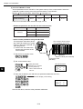
Thank you for purchasing the FL-net module (board) for use with the sharp programmable controller.
JW-20FL5
FL-net module
FL-net board
JW-20FLT
(Installed PC)
JW20H/30H
JW-50FL
JW50H/70H/100H
Z-336J
J-board
Please familiarize yourself with the module by reading this user's manual thoroughly.
Keep this manual handy. We are confident that this manual will be helpful whenever you face a problem.
In addition to this manual, the following manuals are available for your further study.
- JW-20FL5/20FLT
FL-net user's manual (this manual)
- JW-50FL
FL-net user's manual (this manual)
- Z-336J
FL-net user's manual (this manual)
- JW20H/30H
Control module
- JW50H/70H/100H
Control module
- J-board Z-300 series
CPU board
- J-board Z-500 series
CPU board
User's manual - hardware version
Programming manual
User's manual - hardware version
Programming manual
Z-311J/312J user's manual - hardware version
Z-313J* user's manual - hardware version
Z-511J*User's manual - hardware version
* Z-313J and Z-511J (CPU boards) are manufactured on request.
Note
- Should you have any questions or inquires, please feel free to contact one of our dealers, or
our service department.
- Copying this manual in part of in total is prohibited.
- The contents of this manual may be revised without notice.
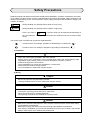
Safety Precautions
Read this manual and attached documents carefully before installation, operation, maintenance and checking in order to use the machine correctly. Understand all of the machine knowledge, safety information, and
cautions before starting to use. In this instruction manual, safety precautions are ranked into "danger" and
"caution" as follows.
Danger
: Wrong handling may possibly lead to death or heavy injury.
Caution
: Wrong handling may possibly lead to medium or light injury.
Even in the case of
Caution , a serious result may be experienced depending on
the circumstances. Anyway, important points are mentioned. Be sure to observe them
strictly.
The picture signs of prohibit and compel are explained below.
: It means don'ts. For example, prohibition of disassembly is indicated as (
: It means a must. For example, obligation of grounding is indicated as (
).
).
1) Installation
Caution
- Use in the environments specified in the user's manual.
Electric shock, fire or malfunction may be caused when used in the environments of high
temperature, high humidity, dusty or corrosive atmosphere, vibration or impact.
- Install according to the user's manual.
Wrong installation may cause drop, breakdown, or malfunction.
- Never admit wire chips or foreign matters.
Or fire, breakdown or malfunction may be caused.
2) Wiring
Compel
- Be sure to ground for programmable controller.
Unless grounded, electric shock or malfunction may be caused.
Caution
- Connect the rated power source.
Connection of a wrong power source may cause a fire.
- Wiring should be done by qualified electrician.
Wrong wiring may lead to fire, breakdown or electric shock.
Caution
- Make sure to follow the descriptions in the instruction manual and user manual when wiring
and installing a module/board.
Make sure to supply the electricians with the wiring and installation requirements.
If the wiring or installation do not meet the specifications, there may be a drop in the modules
ability to reject noise, or the modules may malfunction.
3)
Use
Danger
- Don't touch the terminal while the power is being supplied or you may have an electric shock.
- Assemble the emergency stop circuit and interlock circuit outside of the programmable
controller. Otherwise breakdown or accident damage of the machine may be caused by the
trouble of the programmable controller.
Caution
- Change of program during operation, or "Run" or "stop" during operation should be done with
particular care by confirming safety. Misoperation may lead to damage or accident of the
machine.
- Turn on the power source in the specified sequence. Turning ON with wrong sequence may
lead to machine breakdown or accident.
4)
Maintenance
Prohibit
- Don't disassemble or modify the modules.
Or fire, breakdown or malfunction may be caused.
Caution
- Turn OFF the power source before detaching or attaching the module/board.
Or electric shock, malfunction or breakdown may be caused.
■ User's Manual
Chapter 1: Outline
Chapter 2: Handling Precautions
Chapter 3: System Configuration
Chapter 4: Name and Function of Each Part
Chapter 5: Installation
Chapter 6: Connection/Wiring
Chapter 7: Use Guide
Chapter 8: Cyclic Transfer
Chapter 9: Message Transfers
Chapter 10: Communication Control
Chapter 11: SEND/RECEIVE Function
Chapter 12: Parameters
Chapter 13: Troubleshooting
Chapter 14: Specifications
Chapter 15: Appendix
Alphabetical Index
索
引
Table of Contents
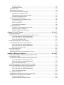
Chapter 1: Outline ...................................................................................................... 1-1
Chapter 2: Handling Precautions ............................................................................. 2-1
Chapter 3: System Configuration ............................................................................. 3-1
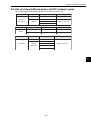
Chapter 4: Name and Function of Each Part .................................................... 4-1 to 4
4-1 JW-20FL5 ..................................................................................................................................... 4-1
4-2 JW-20FLT ..................................................................................................................................... 4-2
4-3 Z-336J ........................................................................................................................................... 4-3
4-4 JW-50FL ....................................................................................................................................... 4-4
Chapter 5: Installation ........................................................................................ 5-1 to 8
5-1 Installation of JW-20FL5/20FLT .................................................................................................... 5-1
5-2 Installation of Z-336J .................................................................................................................... 5-2
[1] Maximum number of boards to mount ........................................................................................ 5-3
[2] Address allocation of I/O relay .................................................................................................... 5-4
(1) When mounted on Z-311J/312J .......................................................................................... 5-4
(2) When mounted on Z-313J ................................................................................................... 5-5
(3) When mounted on Z-511J ................................................................................................... 5-6
5-3 Installation of JW-50FL ................................................................................................................. 5-8
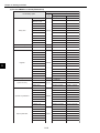
Chapter 6: Connection/Wiring ........................................................................... 6-1 to 9
6-1 Installing an Ethernet cable .......................................................................................................... 6-1
[1] Equipment layout ........................................................................................................................ 6-1
[2] Wiring ......................................................................................................................................... 6-1
6-2 Connection .................................................................................................................................... 6-2
[1] Connection of JW-20FL5 ............................................................................................................ 6-2
(1) Connecting the transciever cable ........................................................................................ 6-2
(2) Wiring the power source ...................................................................................................... 6-3
[2] When connecting to a JW-20FLT ............................................................................................... 6-4
[3] Connection of Z-336J ................................................................................................................. 6-5
(1) When connecting to a 10BASE5 ......................................................................................... 6-5
(2) When connecting to a 10BASE-T ........................................................................................ 6-7
[4] Connection of JW-50FL .............................................................................................................. 6-8
(1) When connecting to a 10BASE5 ......................................................................................... 6-8
(2) When connecting to a 10BASE-T ........................................................................................ 6-9
Chapter 7: Use Guide ........................................................................................ 7-1 to 30
7-1 Ethernet ........................................................................................................................................ 7-1
[1] 10BASE5 system ....................................................................................................................... 7-1
[2] 10BASE-T system ...................................................................................................................... 7-4
[3] IP addresses on an Ethernet ...................................................................................................... 7-5
7-2 FL-net ........................................................................................................................................... 7-6
[1] Description of the FL-net ............................................................................................................ 7-6
[2] The number of modules and their node numbers ...................................................................... 7-8
[3] Data communication type ........................................................................................................... 7-9
(1) Cyclic transfer .................................................................................................................... 7-10
(2) Message transfer ............................................................................................................... 7-10
[4] Transfer data volume ................................................................................................................ 7-10
(1) Cyclic transfer .................................................................................................................... 7-10
(2) Message transfer ................................................................................................................ 7-11
[5] Transfer cycle ............................................................................................................................ 7-11
[6] Data area and memory ............................................................................................................. 7-12
[7] Communication management table .......................................................................................... 7-13
(1) Local node management table .......................................................................................... 7-13
(2) Participating node management table ............................................................................... 7-14
(3) Network management table .............................................................................................. 7-14
[8] Cyclic transfer and data area ................................................................................................... 7-15
(1) Outline of the cyclic transfer process ................................................................................ 7-15
(2) Common memory .............................................................................................................. 7-16
(3) Area 1 and area 2 .............................................................................................................. 7-17
(4) Guarantee of simultaneity ................................................................................................. 7-18
[9] Message transfers ................................................................................................................... 7-19
(1) Outline of the message transfer process ........................................................................... 7-19
(2) Table of support messages ............................................................................................... 7-20
(3) Details of the support messages ....................................................................................... 7-21
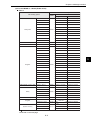
Chapter 8: Cyclic Transfer ................................................................................ 8-1 to 13
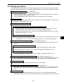
8-1 Setting procedures ........................................................................................................................ 8-3
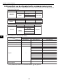
8-2 Areas that can be allocated as the common memory area ........................................................... 8-4
(1) For the JW20H or J-board (Z-300 series) ........................................................................... 8-4
(2) For the JW30H or J-board (Z-500 series) ........................................................................... 8-5
(3) For the JW50H/70H/100H ................................................................................................... 8-6
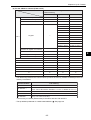
8-3 Parameter settings for cyclic transfers .......................................................................................... 8-7
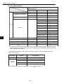
[1] Word addresses used for the top address .................................................................................. 8-8
(1) For the JW20H or J-board (Z-300 series) ........................................................................... 8-8
(2) For the JW30H or J-board (Z-500 series) ........................................................................... 8-9
(3) For the JW50H/70H/100H .................................................................................................. 8-11
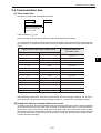
8-4 Communication time ................................................................................................................... 8-13
[1] Token round time ...................................................................................................................... 8-13
[2] Round time when a communication error occurs ..................................................................... 8-13
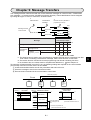
Chapter 9: Message Transfers ......................................................................... 9-1 to 47
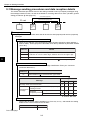
9-1 Message sending procedures and data reception details ............................................................ 9-2
9-2 Transmission buffer....................................................................................................................... 9-4
[1] Allocation of available areas for the transmission buffer ............................................................ 9-5
(1) For the JW20H or J-board (Z-300 series) ........................................................................... 9-5
(2) For the JW30H or J-board (Z-500 series) ........................................................................... 9-6
(3) For the JW50H/70H/100H ................................................................................................... 9-7
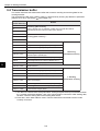
9-3 Message transaction codes and execution conditions ................................................................. 9-8
9-4 Use of virtual address space and PC memory space ................................................................... 9-9
(1) For the JW20H or J-board (Z-300 series) ......................................................................... 9-10
(2) For the JW30H or J-board (Z-500 series) .......................................................................... 9-11
(3) For the JW50H/70H/100H ................................................................................................. 9-14
9-5 Computer link function ................................................................................................................ 9-16
[1] Setting the computer link to send and receive data ................................................................. 9-17
[2] Basic format of computer link commands ................................................................................ 9-19
(1) Communication format ...................................................................................................... 9-19
(2) Memory address expression format .................................................................................. 9-20
(3) Execution condition ...........................................................................................................
(4) Table of commands ...........................................................................................................
[3] Descriptions of each command ................................................................................................
[4] Computer link error code table .................................................................................................
[5] Two-layer communication with the Ethernet .............................................................................
9-6 Remote programming and remote monitor functions .................................................................
[1] Function ....................................................................................................................................
[2] Example operation ...................................................................................................................
9-21
9-22
9-23
9-42
9-43
9-45
9-45
9-46
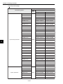
Chapter 10: Communication Control .............................................................. 10-1 to 6
[1] Participating nodes list flag .......................................................................................................
[2] Operation status flag ................................................................................................................
[3] Error status flag ........................................................................................................................
[4] Local node management table .................................................................................................
[5] Participating node management table ......................................................................................
[6] Network management table .....................................................................................................
10-2
10-3
10-4
10-5
10-6
10-6
Chapter 11: SEND/RECEIVE function .............................................................. 11-1 to 8
11-1 Operation of SEND/RECEIVE instruction .................................................................................. 11-2
[1] SEND ........................................................................................................................................11-2
(1) When the module is used (host PC: JW30H, J-board (Z-500 series)) ............................... 11-2
(2) When the module is used (host PC: JW50H/70H/100H) ..................................................... 113
[2] RECEIVE ...................................................................................................................................11-5
(1) When the module is used (host PC: JW30H, J-board (Z-500 series)) ............................... 11-5
(2) When the module is used (host PC: JW50H/70H/100H) .................................................... 11-6
11-2 Timeout time for SEND/RECEIVE instructions .......................................................................... 11-8
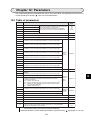
Chapter 12: Parameters .................................................................................... 12-1 to 5
12-1 Table of parameters ..................................................................................................................
12-2 Details of each of the parameters .............................................................................................
(1) Enable/disable the use of the transmission buffer (Setting parameter address 37(8)) .....
12-3 How to set parameters ..............................................................................................................
[1] When the JW-20FL5/20FLT or Z-366J is used .........................................................................
[2] When the JW-50FL is used ......................................................................................................
12-1
12-2
12-2
12-3
12-3
12-4
Chapter 13: Troubleshooting ........................................................................... 13-1 to 6
13-1 Before you conclude that the machine is faulty ........................................................................ 13-1
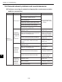
13-2 General network problems and countermeasures .................................................................... 13-2
[1] Problems concerning the network and appropriate countermeasures (when unable to communicate) ......................................................................................................................................... 13-2
[2] Problems concerning the network and appropriate countermeasures (when communications are
unstable) ................................................................................................................................... 13-3
[3] How to check an IP address using the Ping function on a personal computer ........................ 13-4
13-3 General precautions related to the FL-net ................................................................................ 13-5
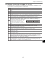
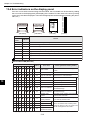
13-4 Error indicators on the display panel ........................................................................................ 13-6
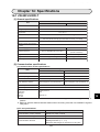
Chapter 14: Specifications ............................................................................... 14-1 to 5
14-1 JW-20FL5/20FLT ......................................................................................................................
[1] General specifications ..............................................................................................................
[2] Communication specifications ..................................................................................................
[3] External dimension drawings ...................................................................................................
14-2 Z-336J .......................................................................................................................................
14-1
14-1
14-1
14-2
14-3
[1] General specifications ..............................................................................................................
[2] Communication specifications ..................................................................................................
[3] External dimension drawings ...................................................................................................
14-3 JW-50FL ...................................................................................................................................
[1] General specifications ..............................................................................................................
[2] Communication specifications ..................................................................................................
[3] External dimension drawings ...................................................................................................
14-3
14-3
14-3
14-4
14-4
14-4
14-5
Chapter 15: Appendix ..................................................................................... 15-1 to 63
15-1 System configuration guide ...................................................................................................... 15-1
[1] Brief description of the Ethernet ............................................................................................... 15-1
[2] 10BASE5 Specifications ........................................................................................................... 15-2
[3] 10BASE-T Specifications ......................................................................................................... 15-3
[4] Other Ethernet Specifications ................................................................................................... 15-4
(1) 10BASE2 ........................................................................................................................... 15-4
(2) Optical Ethernet Specifications ......................................................................................... 15-4
15-2 Examples of system configurations .......................................................................................... 15-5
[1] Small scale configuration ......................................................................................................... 15-5
[2] Basic configuration ................................................................................................................... 15-6
[3] Configuration of a large-scale network ..................................................................................... 15-7
[4] Configuration of a long distance distribution system ................................................................ 15-8
[5] Configuration of local concentrations ....................................................................................... 15-9
[6] Configuration combining local and long distance distribution ................................................. 15-10
[7] Principles of the FL-net system ...............................................................................................15-11
[8] Differences between a general-purpose Ethernet and FL-net ................................................ 15-11
15-3 Definition of network systems ................................................................................................. 15-12
[1] Communication protocol standards ........................................................................................ 15-12
[2] Hierarchical structure of the communication protocols ........................................................... 15-12
[3] Physical implementations of an FL-net .................................................................................. 15-13
[4] IP addresses on the FL-net .................................................................................................... 15-13
[5] FL-net sub net mask ............................................................................................................... 15-14
[6] TCP/IP, UDP/IP protocols ....................................................................................................... 15-14
[7] FL-net port number ................................................................................................................. 15-14
[8] FL-net data format .................................................................................................................. 15-15
(1) Outline of the FL-net data format .................................................................................... 15-15
(2) FL-net header format ....................................................................................................... 15-17
[9] FL-net transaction code .......................................................................................................... 15-17
15-4 Network control of the FL-net ................................................................................................. 15-19
[1] Token control of the FL-net ..................................................................................................... 15-19
(1) Token ............................................................................................................................... 15-19
(2) Flow of the token ............................................................................................................. 15-20
(3) Token and data ................................................................................................................ 15-21
(4) Interval between frames (minimum allowable interval between frames) ......................... 15-22
[2] Joining and leaving an FL-net network ................................................................................... 15-23
(1) Participation in the FL-net ............................................................................................... 15-23
(2) Leaving an FL-net network .............................................................................................. 15-25
[3] Node status control ................................................................................................................ 15-26
[4] FL-net Local node management table .................................................................................... 15-26
[5] FL-net Participating node management table ........................................................................ 15-27
[6] Status management of the FL-net .......................................................................................... 15-28
[7] Control message sequence number of the FL-net ................................................................. 15-28
15-5 Parts needed to build a network ............................................................................................. 15-29
[1] Parts needed to configure an Ethernet ................................................................................... 15-29
[2] Parts related to 10BASE5 ...................................................................................................... 15-30
(1) Transceiver ...................................................................................................................... 15-30
(2) Coaxial cable ................................................................................................................... 15-35
(3) Coaxial connectors .......................................................................................................... 15-35
(4) Relay connector .............................................................................................................. 15-36
(5) Terminator (terminating resistor) ..................................................................................... 15-36
(6) Ground terminal of a coaxial cable .................................................................................. 15-37
(7) Transceiver cable ............................................................................................................ 15-37
(8) 10BASE5/10BASE-T converter ....................................................................................... 15-38
(9) Coaxial/optical converter, repeater .................................................................................. 15-39
[3] 10BASE-T related items ......................................................................................................... 15-40
(1) Hub .................................................................................................................................. 15-40
(2) 10BASE-T cable .............................................................................................................. 15-41
(3) 10BASE-T/optical converter, repeater ............................................................................. 15-41
15-6 Installation of an FL-net network ............................................................................................. 15-42
[1] Wiring 10BASE5 coaxial cable ............................................................................................... 15-42
[2] 10BASE-T (UTP) .................................................................................................................... 15-56
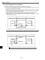
15-7 Grounding the FL-net system ................................................................................................. 15-58
[1] Outline of the grounding procedures for the FL-net system ................................................... 15-58
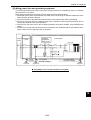
[2] Wiring power lines and grounding equipment ........................................................................ 15-59
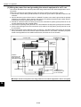
[3] Wiring the power lines and grounding the network equipment in an FL-net .......................... 15-60
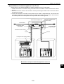
[4] Installation of network equipment in an FL-net ....................................................................... 15-61
[5] Wiring and grounding through wiring ducts and conduits ....................................................... 15-62
15-8 FL-net installation check sheet ............................................................................................... 15-63
Alphabetical Index ............................................................................................... I-1 to 3
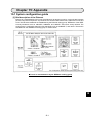
Chapter 1: Outline
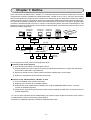
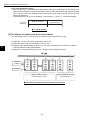
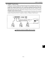
An FL-net module (JW-20FL5/20FLT, JW-50FL, FL-net board (Z-336J)) is an interface module use to connect a
programmable controller (JW20H/30H, JW50H/70H/100H), J-board to an FL-net. FL-net is an open network
that connects production equipment and controllers from multiple FA (factory automation) venders, to create a
unified production process. This network works as an intermediary between information networks and production networks, and makes it possible to connect control devices (such as personal computers or programmable
controllers, hereafter referred to as PCs), to numeric control devices (CNCs), and robot controllers (RCs). The
Ethernet is used as a world standard communication method to allow communication between pieces of OA
(Office Automation) equipment.
EWS
Personal
computer
Server
Personal
computer
Personal
computer
WAN
Information network (Ethernet)
Gateway
FL-net
Image
Robot PC
controller
Nut
runner
NC
Field network
Printer
BCR
ID
Personal
computer
Graphic
panel
Sensor
actuator
FL-net employs an FA link protocol as an application layer.
Features of the FA link protocol
1 Uses the Ethernet UDP/IP communication protocol.
2 Using a Master-less, Token method, the system prevents data transmission conflicts and guarantees
the transfer of data within a specified time.
3 Employs a shared memory system (shares information between each of the nodes).
4 Nodes can automatically enter and leave the network.
Features of the JW-20FL5/20FLT, JW-50FL, Z-336J
1 FL-net compatible (uses the FA link protocol)
2 Supports cyclic transfers and message transfers.
3 Supports exchange of data between SHARP PCs using the SEND/RECEIVE function. (A unique
function of SHARP equipment)
4 Allows remote programming and remote monitor functions between SHARP PCs. (A unique function of
SHARP equipment)
- FL-net is an open network that was standardized by the Japan FA Open Systems Promotion Group (JOP) in
the Manufacturing Science Technology Center (MSTC).
- Ethernet is a registered trademark of XEROX CORPORATION, USA.
1-1
1
Chapter 2: Handling Precautions
Make sure to follow the precautions bellow who using the JW-20FL5/20FLT, JW-50FL (hereafter referred to
as this module) and Z-336J (hereafter referred to as this board).
(1) Installation
- Do not install or store this unit in the following conditions.
1 Locations close to a heating element
2 Sudden temperature changes which may cause condensation
3 Corrosive or inflammable gas
4 Vibration or hard jolts
- The minimum distance between nodes is specified in the regulations. (2.5 m when the 10BASE5
is used.) When connecting devices, be sure to maintain these minimum distances.
Cables used for 10BASE5 systems have marks every 2.5 m. Position each transceiver directly
on one of these marks.
- Mount the transceivers on electrically insulated objects, such as a wooden mounting block.
- Prior to installing or detaching the JW20H/30H or JW50H/70H/100H, make sure to turn OFF the
power supply to the PCs.
- Prior to connect the board, make sure to turn OFF the power to the J-board.
- Isolate the hub case electrically from the control panel chassis.
(2) Treatment
JW-20FL5/20FLT and JW-50FL
- For ventilation, holes are provided in the cabinet to prevent a temperature rise. Do not block
the ventilation holes. Good ventilation is necessary.
- Never allow a liquid such as water and chemical solution and a metallic object like a copper wire
inside this module to avoid a possible hazard. Otherwise, it may be a cause of machine
trouble.
- When a trouble or abnormal condition such as overheat, fume, or smoke is met, stop the
operation immediately, and call your dealer or our service department.
Z-336J
A J-board is a PC board which contains sensitive electronic parts. Therefore, be careful when handling it.
1 Before touching the board with your hand, make sure to discharge all static electricity from
your body.
2 Do not touch the board if your hands are dirty or wet.
3 Do not put the board down on a conductive object (such as a metal plate).
(If a J-board with a CPU is placed on a conductive object, the battery terminals may be short
circuited and the back up memory will be lost.)
4 Do not handle any switches, connectors, or terminal blocks on the J-board using excessive
force.
(3) Grounding
- Connect the J-board FG terminal (on the terminal block on the CPU board) to an independent
class 3 ground. Do not share the ground with high voltage equipment.
- The hexagonal standoffs (supplied with each board) for assembling the J-board are used for
connecting the ground (FG). Make sure to tighten them securely.
(4) Wiring precautions
- Install the communication lines at a distance of 60 cm or more away from motor power lines or
high voltage lines.
- Do not route wires near equipment that generates electrical noise.
- Use category 5 10BASE-T shielded twisted pair cable.
- Use an isolated shield transformer to provide power to the hubs.
- We recommend using a transceiver cable that is 2 m or shorter.
2-1
2
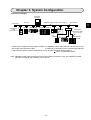
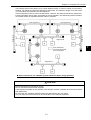
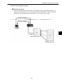
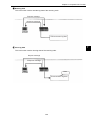
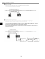
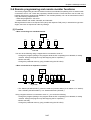
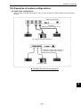
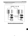
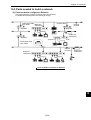
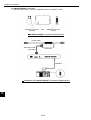
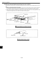
Chapter 3: System Configuration
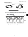
[Connection example]
Personal
computer
10BASE5 coaxial cable (max. 500 m)
FL-net
Terminator
Transceiver
3
J-board JW20H/30H
1
2
Transceiver
cable
(max. 50 m)
RC
Z-336J
JW50H/70H/100H
NC
Hub
RC
JW-20FL5
JW-50FL
Other
maker’s
PC
J-board
10BASE-T
twisted pair cable
(max. 100 m)
1
2
JW20H/30H
JW50H/70H
/100H
JW-20FLT
Z-336J
JW-50FL
- A basic system (segment) configuration consists of a 10BASE5 coaxial cable between 10m and 500 m long
with nodes connected to this cable.
(A maximum of 100 nodes can be connected per segment)
- If the distance between nodes exceeds 500 m, use a repeater (maximum length 2,500 m).
See 7-1[1] 10BASE5 system.
Note: 10BASE5 coaxial cable, transceivers, transceiver cables, terminators, hubs, and 10BASE-T twisted
pair cable is supplied and installed by the customer.
3-1
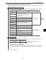
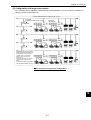
Chapter 4: Name and Function of Each Part
Chapter 4: Name and Function of Each Part
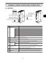
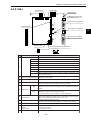
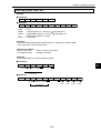
4-1 JW-20FL5
1Display panel
JW-20FL5
LN TX RX 12V
T PE HE
6Module No. switch
S7 S6 S5 S4 S3 S2 S1 S0
(Factory setting: 0)
2Connector for programmer
4 Connector for shield
switch for 10BASE5
4
ON
3Connector for 10BASE5
S
H
I
E
L
D
90
12 3
45
678
512 VDC power supply input terminal
OFF
(Factory setting: ON)
FG
7Reset switch
(Front)
(Rear)
Name
Function
Display panel
1
Displays the JW-20FL5 operating status using LEDs.
LN
Lights when communicating normally.
TX
Blink at transmitting data.
RX
Blink at receiving data.
12 V
Lights when 12 VDC is supplied. (Only when 10BASE5 is used.)
T
Lights at test mode. (Normally, this is not used.)
PE
Lights at parameter setting error.
HE
Lights at this module error.
S0 to S7
Displays the station number when operating normally. Displays an error
code if an error occurs.
2
Connector for programmer
Connect a JW-14PG programmer or similar equipment to set the
parameters on the JW-20FL5.
3
Connector for 10BASE5
Connect the 10BASE5 transceiver cable.
Make sure to slide the lock securely to the "lock" position.
4
Connector for
Shield switch
for 10BASE5
ON
The shield on the coaxial cable and the FG (base) terminal on this
module will be shorted together.
OFF
The shield on the coaxial cable is not shorted to the base.
- Ground the FG line on the 12 VDC connector separately.
12 VDC power supply
5 input terminal
6
Module No. switch
7 Reset switch
When 10BASE5 is used, connect a commercially available DC power
supply that is designed to supply power to transceivers. The DC power
supply must provide 12VDC ±5% and 0.5 A or more.
Specify a module number from 0 to 6.
- Be careful do not use the same number for another option module.
Only used by SHARP engineers. Users should not press this switch.
4-1
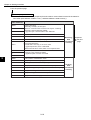
Chapter 4: Name and Function of Each Part
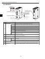
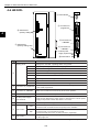
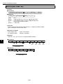
4-2 JW-20FLT
1Display panel
JW-20FLT
LN TX RX 12V
T PE HE
S7 S6 S5 S4 S3 S2 S1 S0
5Module No. switch
2Connector for programmer
(Factory setting: 0)
4 Connector for shield
switch for 10BASE-T
ON
S
H
I
E
L
D
90
12 3
678
3Connector for 10BASE-T
45
4
OFF
(Factory setting: ON)
6Reset switch
(Front)
(Rear)
Name
Function
Display panel
1
Displays the JW-20FLT operating status using LEDs.
LN
Lights when communicating normally.
TX
Blink at transmitting data.
RX
Blink at receiving data.
12 V
Cannot be used with the JW-20FLT.
T
Lights at test mode. (Normally, this is not used.)
PE
Lights at parameter setting error.
HE
Lights at this module error.
S0 to S7
Displays the station number when operating normally. Displays an error
code if an error occurs.
2
Connector for programmer
Connect a JW-14PG programmer or similar equipment to set the
parameters on the JW-20FLT.
3
Connector for 10BASE-T
Connect the 10BASE-T twisted pair.
4
Connector for
Shield switch
for 10BASE-T
The shield on the twisted pair cable will be shorted to the FG (base) of
this module.
5
Module No. switch
6 Reset switch
ON
OFF
The shield on the twisted pair cable is not shorted to the base.
Specify a module number from 0 to 6.
- Be careful do not use the same number for another option module.
Only used by SHARP engineers. Users should not press this switch.
4-2
Chapter 4: Name and Function of Each Part
9Switch SWA
8Reset switch
O
F
F
O
F
F
Factory setting
: ON
1
2
3
1
SW1
2
Factory setting
: ON
0Switch SW1
7Module No. switch SW4
SWA
456
T
12V
RX
TX
LN
SWA
ON
1
SW1
2
901
O
F
F
78
(Factory setting: 0)
23
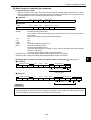
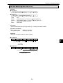
4-3 Z-336J
2Connector for programmer
⑧
⑦
S0
S1
S2
S3
S4
S5
S6
S7
HE
PE
1Display panel
②
3Connector for 10BASE-T
S0
S1
S2
S3
S4
S5
S6
S7
HE
PE
T
12V
RX
TX
LN
4
③
4Connector for 10BASE5
④
SW6
ON
5Switch SW6
612 VDC power supply input terminal
SW6
FG 0V 12V
(Factory setting: ON)
ON
Name
Function
Display panel
1
Displays this board operating status using LEDs.
LN
Lights when communicating normally.
TX
Blink at transmitting data.
RX
Blink at receiving data.
12 V
Lights when 12 VDC is supplied. (Only when 10BASE5 is used.)
T
Lights at test mode. (Normally, this is not used.)
PE
Lights at parameter setting error.
HE
Lights at this board error.
S0 to S7
Displays the station number when operating normally. Displays an error
code if an error occurs.
2
Connector for programmer
Connect a JW-14PG programmer or similar equipment to set the
parameters on this board.
3
Connector for 10BASE-T
Connect the 10BASE-T coaxial cable.
4
Connector for 10BASE5
Connect the 10BASE5 coaxial cable.
Make sure to slide the lock securely to the "lock" position.
5
ON
The shield on the cable between a 10BASE-T connector and a
10BASE5 connector and the FG (base) on this module will be shorted
together.
OFF
The shield on the cable between a 10BASE-T connector and a
10BASE5 connector is not shorted to the base.
- Ground the FG line on the 12 VDC connector separately.
Switch SW6
6
12 VDC power supply
input terminal
When 10BASE5 is used, connect a commercially available DC power
supply that is designed to supply power to transceivers. The DC power
supply must provide 12VDC ±5% and 0.5 A or more.
7
Module No. switch
Specify a module number from 0 to 6.
- Be careful do not use the same number for another option board.
8 Reset switch
Only used by SHARP engineers. Users should not press this switch.
9
Number of communication Specify the number of communication boards actually installed
(including the Z-336J).
boards
- See pages 5-3 to 5-7.
Switch SWA
0
Switch SW1
No need to set this switch for the Z-336J. (Always set to OFF (default).)
4-3
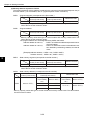
Chapter 4: Name and Function of Each Part
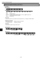
4-4 JW-50FL
JW-50FL
1 LED indicator
LNK
TX
RX
DC12V
TEST
4
2 Connector for
programmer
SW3
78
8 Switch SW3
(Factory setting: 0)
23
456
901
PER
HER
P
R
O
G
R
A
M
M
E
R
3 Connector for
10BASE5
7 Switch SW3
(Factory setting: ON)
10B5
4 Connector for
10BASE-T
5 12 VDC power
supply input terminal
OFF ON
SW2
6 Reset switch
Name
10B-T
12VIN
(+)
(−)
FG
RESET
Function
Display panel
1
S0
S1
S2
S3
S4
S5
S6
S7
Displays the JW-50FL operating status using LEDs.
LNK
Lights at operating. Lights OFF at stopping.
TX
Blink at transmitting data.
RX
Blink at receiving data.
12 VDC
Lights when 12 VDC is supplied. (Only when 10BASE5 is used.)
TEST
Lights at test mode.
PER
Lights at parameter setting error.
HER
Lights at this module error.
S0 to S7
Indicates status of connection status monitor flag.
2
Connector for programmer
When using a remote monitor or remote programming function, connect
a JW-14PG programmer.
3
Connector for 10BASE5
Connect the 10BASE5 transceiver cable.
Make sure to slide the lock securely to the "lock" position.
4
Connector for 10BASE-T
Connect 10BASE-T twisted-pair cable.
5
12 VDC power supply
input terminal
When 10BASE5 is used, connect a commercially available DC power
supply that is designed to supply power to transceivers. The DC power
supply must provide 12VDC 5% and 0.5 A or more.
6 Reset switch
7
8
Only used by SHARP engineers. Users should not press this switch.
ON
Turn ON when the shields on the 10BASE-T connectors or 10BASE5
connectors are connected to the FG (base) of the JW-50FL.
OFF
Turn OFF when the shields on the 10BASE-T connectors or 10BASE5
connectors are not connected to the FG.
- Ground the FG line on the 12 VDC connector separately.
Switch SW2
Switch SW3
Specify a parameter address (in system memory) from 0 to 4.
- See page 12-4.
Note: Only 10BASE5 or 10BASE-T protocol is used. Mixed use of these two types is not permitted.
4-4
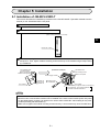
Chapter 5: Installation
Chapter 5: Installation
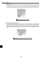
5-1 Installation of JW-20FL5/20FLT
This section describes the installation procedures for the JW-20FL5/20FLT (hereafter referred to as the
module) on the JW20H/30H basic rack panel.
Turn off the power to the JW20H/30H.
Set the module No. switch on the back of the module.
(Back of the communication module)
5
Module No. switch
Insert the mounting rib on the module into the rib insert holes on the JW20H/30H basic rack panel
and push in. Then, tighten module-mounting screws at the top of the module using a Phillips-head
(+) screwdriver.
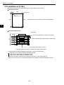
Intermediate plate
or control panel
Basic rack panel
Module insert guide
(Installation example)
Ventilation hole
Module mounting screw
Basic rack panel
Power supply module
This module
Module rib
insert hole
Module rib
+ Phillips-head
screwdriver
The module
Control module (The figure shows a JW-20FL5.)
JW-21CU/22CU, JW-31CUH1/32CUH1
JW-33CUH1/33CUH2/33CUH3
Notes
- The module cannot be installed into an expansion rack panel.
- More than two communication modules can be installed on the same control module (basic rack panel
for the JW20H/30H). However, be careful not to use the same module No. switch setting for any other
module (including JW-20FL5/20FLT).
- Make sure to tighten the module mounting screws securely. Loose screws may cause a malfunction.
5-1
Chapter 5: Installation
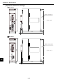
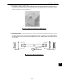
5-2 Installation of Z-336J
Board dimensions and assembled dimensions of the Z-336J are shown below.
Board dimensions
5
100
5
[Unit: mm]
Boss hole: 4-φ4
170
180
The dimensions on the left do not include metal fittings.
5
5
110
Assembled dimensions
[Unit: mm]
25.0
* CPU board (when Z-311J/312J is mounted)
21.6
D
When installing the Z-336J under the CPU board.
D2
D2
D2
15.0
In the case metal fixing A is used.
* The CPU board can only be installed at the upper most position.
- For details about assembly/installation dimensions, see the manuals below.
J-board Z-311J/312J User's Manual: Hardware Version.
J-board Z-313J User's Manual: Hardware Version.
J-board Z-511J User's Manual: Hardware Version.
Dimensions D and D2 correspond to D and D2 "board sizes" of the manuals above.
- Make sure to ensure there is conductivity between the installation metal and installation section.
5-2
Chapter 5: Installation
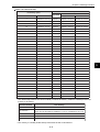
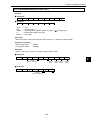
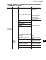
This paragraph describes the maximum number of Z-336J boards to install on the J-board and allocation of I/O
relays.
Allocation of I/O relays
When mounted on the Z-311J/312J
See the next page.
When mounted on the Z-313J
See page 5-5.
When mounted on the Z-511J
See page 5-6.
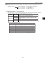
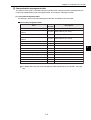
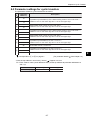
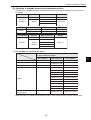
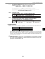
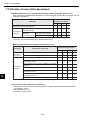
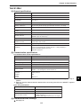
[1] Maximum number of boards to mount
The Z-336J is a kind of communication board of the J-board. Maximum number of boards mounted on
the J-board shall be the total number of communication boards mounted.
J-board
CPU board
Z-311J
Z-300 series
Z-500 series
Z-312J
Total number of boards able to be mounted including
Z-336J and other communication boards
Maximum 2
- When the total current flow at 5 V of each mounted
board exceeds 800 mA, the number of boards shall be
limited.
Z-313J *
Maximum 1
Z-511J *
Maximum 2
Types of communication boards
Module name
Specifications
Z-331J *
Data link or computer link, satellite I/O link master station
Z-332J
Data link or computer link
Z-333J
Satellite I/O link master station
Z-334J *
ME-NET board (with branch line extension function)
Z-335J
Satellite net board
Z-336J
FL-net board
Z-337J
DeviceNet board
* Manufactured on request.
5-3
5
Chapter 5: Installation
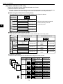
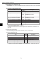
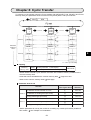
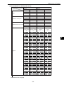
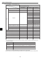
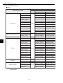
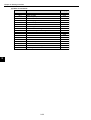
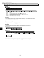
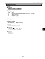
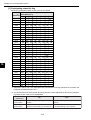
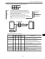
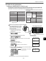
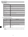
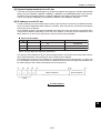
[2] Address allocation of I/O relay
This section describes I/O relay addresses allocated to the Z-336J.
(1) When mounted on Z-311J/312J
The total number of Z-336J boards able to be mounted including other communication boards is two
at maximum. Below the switch settings of the Z-336J and allocation of I/O relay are shown.
When using one communication board (Z-336J)
Set switch SWA for number of communication boards on the Z-336J as follows.
Setting of
switch SWA
on the Z-336J
1 2
ON ON
Address to set
コ 0000
コ 0001
コ 0002
コ 0003
コ 0004
コ 0005
コ 0006
コ 0007
Z-336J
(optional)*
Dummy
(vacant)
Dummy
(vacant)
Dummy
(vacant)
R = 0, S = 0
R = 0, S = 1
* Though it is allocated as optional,
it will be a dummy area not
functionally used.
R = 0, S = 2
R = 0, S = 3
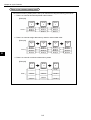
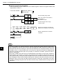
When using two communication boards
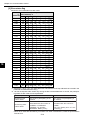
Depending on at which position the Z-336J is used, the allocation of I/O relay varies.
Use Z-336J as first unit
Setting of
switch SWA
on the Z-336J
Use Z-336J as 2nd unit
1 2
ON ON
I/O relay address
Allocation of Z-336J
I/O relay
5
Allocation of Z-336J
I/O relay
I/O relay address
コ 0000
コ 0001
コ 0002
コ 0003
コ 0004
コ 0005
コ 0006
コ 0007
Z-336J
(optional)*
Dummy
(vacant)
Dummy
(vacant)
Dummy
(vacant)
1 2
OFF ON
Address to set
R = 0, S = 0
R = 0, S = 1
R = 0, S = 2
R = 0, S = 3
I/O relay address
コ 0010
コ 0011
コ 0012
コ 0013
コ 0014
コ 0015
コ 0016
コ 0017
Address to set
R = 0, S = 4
R = 0, S = 5
R = 0, S = 6
R = 0, S = 7
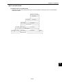
Examples of allocation
Below the switch setting and I/O allocation when using two Z-336J is shown.
Mounted
SW1
SWA
position (RACK NO) (SW2)
Z-336J
Z-336J
4
Z-322J
Z-322J
3
Z-311J
2
/312J
1
ON
OFF
1
1 2 3
SW2
1 2
2
1 2 3
SW2
1 2
3
1 2 3
SWA
1 2
4
1 2 3
SWA
1 2
5-4
I/O relay
Address to set
address
コ 0020, コ 0021 R=1, S=0
コ 0022, コ 0023 R=1, S=1
コ 0024, コ 0025 R=1, S=2
コ 0026, コ 0027 R=1, S=3
コ 0030, コ 0031 R=2, S=0
コ 0032, コ 0033 R=2, S=1
コ 0034, コ 0035 R=2, S=2
コ 0036, コ 0037 R=2, S=3
コ 0000, コ 0001 R=0, S=0
コ 0002, コ 0003 R=0, S=1
コ 0004, コ 0005 R=0, S=2
コ 0006, コ 0007 R=0, S=3
コ 0010, コ 0011 R=0, S=4
コ 0012, コ 0013 R=0, S=5
コ 0014, コ 0015 R=0, S=6
コ 0016, コ 0017 R=0, S=7
Chapter 5: Installation
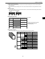
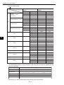
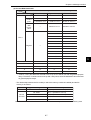
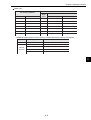
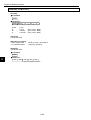
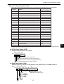
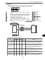
(2) When mounted on Z-313J
The number of boards available mounted on the Z-336J including other communication boards is
one at maximum.
Below shows the switch setting of the Z-313J and Z-336J as well as I/O relay allocation of the Z336J.
Switch setting
The set switch SWA on the Z-313J and the number of communication boards setting switch SWA of
the Z-336J are as shown below.
- Z-313J
Switch SWA
1 2
ON
ON
- Z-336J
Switch SWA
1 2
OFF
ON
Allocation of I/O relay
I/O relay address of the Z-336J shall be allocated as shown below.
Allocation
details
I/O relay address
Z-336J
(optional)*
コ 0010
コ 0011
Dummy
(vacant)
コ 0012
コ 0013
コ 0014
コ 0015
コ 0016
コ 0017
Dummy
(vacant)
Dummy
(vacant)
Address to set
R = 0, S = 4
R = 0, S = 5
* Though it is allocated as optional,
it will be a dummy area not
functionally used.
R = 0, S = 6
R = 0, S = 7
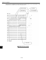
Allocation examples
Below shows switch setting and I/O relay allocation when using one Z-336J.
Mounted
I/O relay
SW1
SWA
Address to set
position (RACK NO.)
(SW2) address
R=0, S=0
Z-325J
SWA コ 0000, コ 0001
コ 0002, コ 0003
R=0, S=1
Z-325J
1
2
NO
4
1
コ 0004, コ 0005
R=0, S=2
Z-313J
3
コ 0006, コ 0007
R=0, S=3
コ 0020, コ 0021
R=1, S=0
2
SW2 コ 0022, コ 0023
R=1, S=0
1
1 2 コ 0024, コ 0025
1 2 3
R=1, S=1
2
コ 0026, コ 0027
R=1, S=2
コ 0030, コ 0031
R=1, S=3
コ 0032, コ 0033
R=2, S=0
SW2 コ 0034, コ 0035
R=2, S=0
1 2 3
3
1 2 コ 0036, コ 0037
R=2, S=1
コ 0040, コ 0041
R=2, S=2
コ 0042, コ 0043
R=2, S=3
コ
0010,
コ
0011
R=0, S=4
ON
SWA
R=0, S=5
OFF
1 2 コ 0012, コ 0013
4
1 2 3
コ 0014, コ 0015
R=0, S=6
コ 0016, コ 0017
R=0, S=7
Z-336J
5-5
5
Chapter 5: Installation
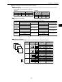
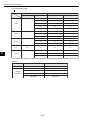
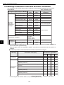
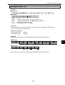
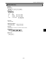
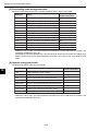
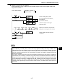
(3) When mounted on Z-511J
The number of boards available mounted on the Z-336J including other communication boards is
two at maximum.
Below shows the switch setting of the Z-511J and Z-336J as well as I/O relay allocation of the Z336J.
When using one communication board (Z-336J)
Switch setting
The set switches SW1 and SWA on the Z-511J and the number of communication boards setting
switch SWA on the Z-336J are as follows.
- Z-336J
- Z-511J
Switch SW1
Switch SWA
Switch SWA
1 2
1 2 3
1 2
OFF
OFF
OFF
ON
ON
OFF
ON
5
Allocation of I/O relay
I/O relay address of the Z-336J shall be allocated as shown below.
Allocation
details
I/O relay address
Z-336J
(optional)*
Dummy
(vacant)
Dummy
(vacant)
Dummy
(vacant)
コ 0010
コ 0011
コ 0012
コ 0013
コ 0014
コ 0015
コ 0016
コ 0017
Address to set
R = 0, S = 4
R = 0, S = 5
* Though it is allocated as optional,
it will be a dummy area not
functionally used.
R = 0, S = 6
R = 0, S = 7
Allocation examples
Below shows switch setting and I/O relay allocation when using one Z-336J.
Mounted
SW1
SWA
position (RACK NO) (SW2)
Z-336J
Z-322J
4
Z-322J
Z-511J
3
2
1
ON
OFF
1
1 2 3
SWA
1 2
2
1 2 3
SW2
1 2
3
1 2 3
SW2
1 2
4
1 2 3
SW2
1 2
5-6
I/O relay
Address to set
address
コ 0000, コ 0001 R=0, S=0
コ 0002, コ 0003 R=0, S=1
コ 0004, コ 0005 R=0, S=2
コ 0006, コ 0007 R=0, S=3
コ 0020, コ 0021 R=1, S=0
コ 0022, コ 0023 R=1, S=1
コ 0024, コ 0025 R=1, S=2
コ 0026, コ 0027 R=1, S=3
コ 0030, コ 0031 R=2, S=0
コ 0032, コ 0033 R=2, S=1
コ 0034, コ 0035 R=2, S=2
コ 0036, コ 0037 R=2, S=3
コ 0010, コ 0011 R=0, S=4
コ 0012, コ 0013 R=0, S=5
コ 0014, コ 0015 R=0, S=6
コ 0016, コ 0017 R=0, S=7
Chapter 5: Installation
When using two communication boards (Z-336J)
Switch setting
The set switches SW1 and SWA on the Z-551J and the number of communication boards setting
switch SWA on the Z-336J are as follows.
- Z-336J
- Z-511J
Use Z-336J
Use Z-336J
Switch SW1
Switch SWA
as 1st unit
as 2nd unit
1 2 3
1 2
Switch
SWA
Switch
SWA
OFF
OFF
OFF
ON
ON
1 2
1 2
ON
ON
OFF
ON
Allocation of I/O relay
I/O relay address of the Z-336J shall be allocated as shown below.
Allocation
details
Z-336J
(optional)*
Dummy
(vacant)
Dummy
(vacant)
Dummy
(vacant)
Use Z-336J as 1st unit
I/O relay address
Address to set
コ 0000
R = 0, S = 0
コ 0001
コ 0002
R = 0, S = 1
コ 0003
コ 0004
R = 0, S = 2
コ 0005
コ 0006
R = 0, S = 3
コ 0007
Use Z-336J as 2nd unit
I/O relay address
Address to set
コ 0010
R = 0, S = 4
コ 0011
コ 0012
R = 0, S = 5
コ 0013
コ 0014
R = 0, S = 6
コ 0015
コ 0016
R = 0, S = 7
コ 0017
* Though it is allocated as optional, it will be a dummy area not functionally used.
Allocation examples
Below shows switch setting and I/O relay allocation when using two Z-336Js.
Mounted
SW1
SWA
position (RACK NO) (SW2)
Z-336J
Z-336J
4
Z-322J
Z-511J
3
2
1
ON
OFF
1
1 2 3
SWA
1 2
2
1 2 3
SWA
1 2
3
1 2 3
SWA
1 2
4
1 2 3
SWA
1 2
5-7
I/O relay
Address to set
address
コ 0020, コ 0021 R=1, S=0
コ 0022, コ 0023 R=1, S=1
コ 0024, コ 0025 R=1, S=2
コ 0026, コ 0027 R=1, S=3
コ 0030, コ 0031 R=2, S=0
コ 0032, コ 0033 R=2, S=1
コ 0034, コ 0035 R=2, S=2
コ 0036, コ 0037 R=2, S=3
コ 0000, コ 0001 R=0, S=0
コ 0002, コ 0003 R=0, S=1
コ 0004, コ 0005 R=0, S=2
コ 0006, コ 0007 R=0, S=3
コ 0010, コ 0011 R=0, S=4
コ 0012, コ 0013 R=0, S=5
コ 0014, コ 0015 R=0, S=6
コ 0016, コ 0017 R=0, S=7
5
Chapter 5: Installation
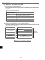
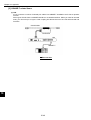
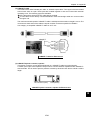
5-3 JW-50FL
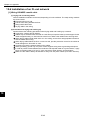
(1) Installation of cable for option module
Install the optional cable on the basic rack panel that installed JW-50FL.
Cable type for option module
Cable for option module
ZW-2CC
ZW-4CC
ZW-6CC
Maximum number of JW-50FL
that can be installed
2
4
Note *
5
* If the ZW-6CC is used, a maximum of 6 optional modules can be installed. However, a limit of
5 optional modules can be used with JW-50FL, due to a parameter (address area) setting limitation.
5
Rack panel type
Model name of the rack
panel on which optional
cable is installed
Cable for option module
( : Can be installed
: Cannot be installed)
ZW-2CC
ZW-4CC ZW-6CC
JW-4BU
JW-6BU
JW-8BU
JW-13BU
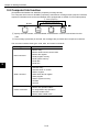
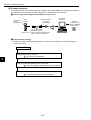
(2) Installation of JW-50FL
Attach the rack panel using the two attachment screws.
Before installation or removal, make sure to shut OFF the power supply to the PC.
Install on rack panel JW-4BU
Module
Rack panel
Appearance when ZW-2CC optional
cable is installed
Phillips screwdriver
- This module can be installed in any one of the optional slots.
Be careful not to bend the connector pins on the module by applying
too much force to them.
5-8
Chapter 6: Connection/Wiring
Chapter 6: Connection/Wiring
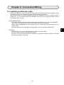
6-1 Installing an Ethernet cable
Workers who will install or hook up an Ethernet cable must have special training and knowledge, such as
the safety procedures and standards required by this technology (JIS X5252).
We recommend that you contact a specialist for perform any installation or hook up. (Sharp Document
Systems Co., Ltd. is providing the Ethernet installation work service, and supplying network products
from Allied System Co., Ltd.)
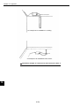
[1] Equipment layout
- The minimum distance between nodes is specified in the regulations. (2.5 m when the 10BASE5 is
used.) When connecting devices, be sure to maintain these minimum distances.
Cables used for 10BASE5 systems have marks every 2.5 m. Position each transceiver directly on one
of these marks.
- Mount the transceivers on electrically insulated objects, such as a wooden mounting block.
6
[2] Wiring
- Separate (60 cm or more) the data transmission cables from power cables.
- Do not run cables near any noise generating source.
- Both ends of the coaxial cable must be terminated with a termination resistance. Make sure to install
termination resistance on each end.
6-1
Chapter 6: Connection/Wiring
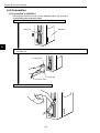
6-2 Connection
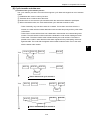
[1] Connection of JW-20FL5
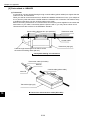
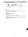
This paragraph describes how to connect 10BASE5 cable to the JW-20FL5.
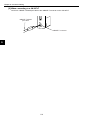
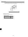
(1) Connecting the transceiver cable
1 Slide the lock on the 10BASE5 connector (on the JW-20FL5) up.
Slide lock
JW-20FL5
RESET
6
2 Insert the connector so that the two locking posts on the cable connector match the holes on
the slide lock.
Locking post
RESET
Locking post
Transceiver cable
3 Slide the lock down to lock the cable connector.
RESET
6-2
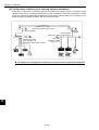
Chapter 6: Connection/Wiring
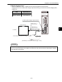
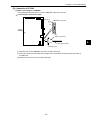
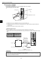
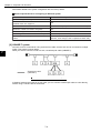
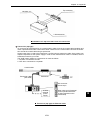
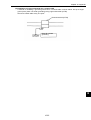
(2) Wiring the power source
When a 10BASE5 is used, 12 VDC power should be supplied to the transceiver.
Supply power to the 12 VDC power supply input terminal using a commercial constant voltage power
supply unit.
Item
JW-20FL5
Specifications
Supply voltage
Current capacity
12 VDC –5%
LN TX RX 12V
T PE HE
S7 S6 S5 S4 S3 S2 S1 S0
0.5 A minimum.
12 VDC power supply input terminal
Black wire (-)
ON
S
H
I
E
L
D
OFF
* Fuse (0.6 A)
Red wire (+)
6
Twisted pair wires
(+)
12 VDC
(−)
FG
RESET
* Use a fuse melt with time lag
Case
Green wire
(ground)
Cable
(Accessory: Connector, cable length 1.5 m)
Remarks
- Use a power supply that is dedicated for use by the JW-20FL5.
- Do not reverse the positive and negative connections to the power terminals. Reversing the polarity
may damage the JW-20FL5.
6-3
Chapter 6: Connection/Wiring
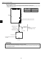
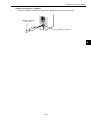
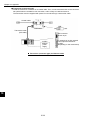
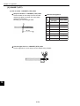
[2] When connecting to a JW-20FLT
Connect a 10BASE-T twisted pair cable to the 10BASE-T connector on the JW-20FLT.
10BASE-T twisted
pair cable
10BASE-T connector
6
6-4
Chapter 6: Connection/Wiring
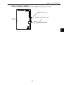
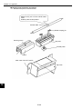
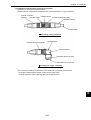
[3] Connection of Z-336J
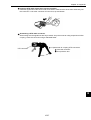
(1) When connecting to a 10BASE5
This paragraph describes how to connect 10BASE5 cable to the Z-336J.
Connecting the transceiver cable
O
F
F
T
12V
RX
TX
LN
SWA
ON
1
SW1
2
Slide lock
1
↑↓
3
10BASE5 connector
S0
S1
S2
S3
S4
S5
S6
S7
HE
PE
Z-336J
Cable connector
2
SW6
6
ON
Transceiver cable
Locking post
1 Slide the lock on the 10BASE5 connector (on the Z-336J) up.
2 Insert the connector so that the two locking posts on the cable connector match the holes on
the slide lock.
3 Slide the lock down to lock the cable connector.
6-5
Chapter 6: Connection/Wiring
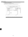
Wiring the power source
When a 10BASE5 is used, 12 VDC power should be supplied to the transceiver.
Supply power to the 12 VDC power supply input terminal of the Z-336J using a commercial constant
voltage power supply unit.
O
F
F
T
12V
RX
TX
LN
SWA
ON
1
SW1
2
Item
Specifications
Supply voltage
12 VDC –5%
Current capacity
0.5 A minimum.
S0
S1
S2
S3
S4
S5
S6
S7
HE
PE
Z-336J
12 VDC power supply input terminal
SW6
6
ON
Twisted pair wires
Green wire
(ground)
Red wire (+)
Cable
(Accessory: Connector,
cable length 1.5 m)
Black wire (-)
Case
* Fuse (0.6 A)
* Use a fuse that will melt with
time lag
(+)(−)
12 VDC
Remarks
- Use a power supply that is dedicated for use by the Z-336J.
- Do not reverse the positive and negative connections to the power terminals. Reversing the polarity
may damage the Z-336J.
6-6
Chapter 6: Connection/Wiring
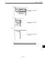
(2) When connecting to a 10BASE-T
Connect a 10BASE-T twisted pair cable to the 10BASE-T connector on the Z-336J.
O
F
F
T
12V
RX
TX
LN
SWA
ON
1
SW1
2
S0
S1
S2
S3
S4
S5
S6
S7
HE
PE
10BASE-T connector
10BASE-T twisted pair cable
Z-336J
SW6
ON
6
6-7
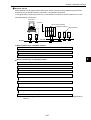
Chapter 6: Connection/Wiring
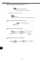
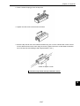
[4] Connection of JW-50FL
(1) Connection of 10BASE5
This paragraph describes how to connect 10BASE5 cable to the JW-50FL.
Connecting the transceiver cable
Slide lock
①
↑↓
③
Locking post
②
10BASE5 connector
Locking post
Transceiver cable
6
1 Slide the lock on the 10BASE5 connector (on the JW-50FL) up.
2 Insert the connector so that the two locking posts on the cable connector match the holes on
the slide lock.
3 Slide the lock down to lock the cable connector.
Wiring the power source
When a 10BASE5 is used, 12 VDC power should be supplied to the transceiver.
Supply power to the 12 VDC power terminals using a commercial constant voltage power supply
unit.
Item
Specifications
Supply voltage
12 VDC –5%
Current capacity
0.5 A minimum.
10B5
Black wire (-)
* Fuse (0.6 A)
Red wire (+)
10B-T
Twisted pair wires
(+)
12 VDC
(−)
* Use a fuse melt with time lag
Case
12VIN
(+)
(−)
FG
RESET
Green wire
(ground)
Cable
(Accessory: Connector, cable length 1.5 m)
Remarks
- Use a power supply that is dedicated for use by the JW-50FL.
- Do not reverse the positive and negative connections to the power terminals. Reversing the
polarity may damage the JW-50FL.
6-8
Chapter 6: Connection/Wiring
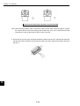
(2) When connecting to a 10BASE-T
Connect a 10BASE-T twisted pair cable to the 10BASE-T connector on the JW-50FL.
10BASE-T twisted
pair cable
10BASE-T connector
6
6-9
Chapter 7: Computer Link Function
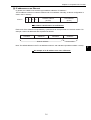
Chapter 7: Use Guide
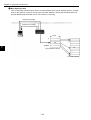
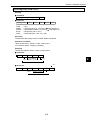
7-1 Ethernet
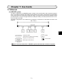
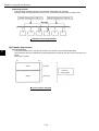
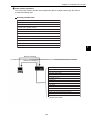
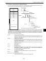
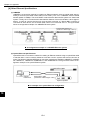
[1] 10BASE5 system
The basic configuration of a10BASE5 system consists of one coaxial cable, with a maximum length of
500 m, and nodes connected to this cable as shown below. Each node is connected to the coaxial cable
using a transceiver and a transceiver cable (AUI cable). Two types of transceivers are available: Single
port transceivers to connect a single transceiver cable (AUI cable), and multi-port transceivers to connect more than one cable.
This basic configuration unit is referred to as "segment." A maximum of 100 nodes can exist in one
segment.
Max. 500 m
Segment
7
: Coaxial cable
: Node
: Transceiver cable (AUI cable)
: Singe port transceiver
: Terminator
: Multi-port transceiver
Basic connection method for a 10BASE5 system (maximum 500 m without a repeater)
7-1
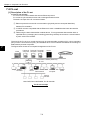
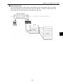
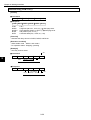
Chapter 7: Computer Link Function
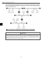
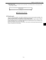
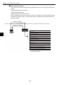
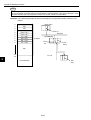
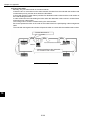
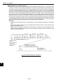
If the distance between nodes is greater than 500 m, connect a repeater as shown below, or to increase
the number of segments by branching. The figure below is an example of a system with a maximum of
1500 m of cable. Arrange the configuration so that there are never more than two repeaters between
any two nodes along any path.
7
Basic connections in a 10BASE5 system (maximum 1500 m using repeaters)
CAUTION
Connect the repeater to the coaxial cable through a transceiver and transceiver cable. Repeaters
can be connected to any transceiver in the same segment. The installation distance between
transceivers is considered to be a multiple of "2.5m" lengths. That is, any cable length should be
evenly divisible by 2.5 m and not have a remainder.
7-2
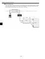
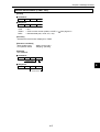
Chapter 7: Computer Link Function
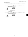
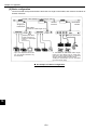
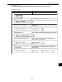
The example shown below allows up to 2,500m between nodes. In order to extend communication
distance, link cables are used (with repeaters at both ends). The maximum length of one link is 500
m. These cables are referred to as "link segments."
The link segments must not connect nodes directly. However, the areas surrounded by dotted lines,
including repeaters at both ends, are treated as a single repeater. This does away with the limitation
on the total number of repeaters between nodes in a system.
Link segment 1
Link segment 3
Segment B
Segment C
Segment A
Link segment 2
: Area inside this
rectangle is treated
as one repeater
Segment D
Basic connections in a 10BASE5 system (maximum 2500 m using repeaters)
CAUTION
Each link segment must be 500 m or less.
Do not connect a node to the link segment.
A link segment is treated as one repeater, even though it includes a repeater at each end (enclosed
with dotted lines).
No more than two repeaters shall exist along the path between any two nodes.
Only one segment in the network can be connected to more than two repeaters.
7-3
7
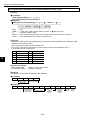
Chapter 7: Computer Link Function
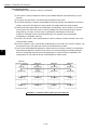
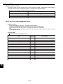
Parameters related to the system configuration are summed up below.
General specifications for configuring an Ethernet system
Item
Specifications
Maximum length of a segment
500 m
Maximum number of transceivers that can be
installed within one segment
100
Maximum distance between nodes
2500 m or less (except for the transceiver cables)
Maximum number of nodes in a system
254
Maximum length of transceiver cable (AUI cable) 50 m
Cable length between transceiver and repeater
2 m or less (recommended)
Maximum number of repeaters between two
nodes
2 (However, a link segment is treated as one
repeater, even though it has a repeater at each end.)
[2] 10BASE-T system
7
Connect a hub to a transceiver using a transceiver cable, and the hub can be connected to multiple
nodes. This system is shown below.
When you want to connect a node to a hub, use twisted pair cable (10BASE-T).
: Twisted pair cable
(10BASE-T)
Basic connections in a 10BASE-T system
If distance between the nodes is not too great, you can connect a twisted pair cable to a hub directly,
without using a coaxial cable or transceiver.
7-4
Chapter 7: Computer Link Function
[3] IP addresses on an Ethernet
In general, the UDP/IP uses a 32-bit logical address called the "IP address."
The IP address consists of a network address and a host address. Normally, a class C configuration is
used in the FA industry.
Class C
1
1
0
Host address
(8 bits)
Network address
(20 bits)
X
IP address classifications on an Ethernet
Each 8 bits of the address are separated by a period and can be expressed as a decimal number. For
example, class C IP addresses are expressed as follows.
11000000
00000010
00000000
00000011
192
001.
000.
003.
Network address
Host number
Note: The default address in the FL-net address scheme is 192.168.250.N (N: Node numbers 1 to 254).
An example of an IP address on a class C Ethernet
7-5
7
Chapter 7: Computer Link Function
7-2 FL-net
[1] Description of the FL-net
(1) The FL-net concept
FL-net is an FA control network that uses an Ethernet protocol.
FL-net has a cyclic transfer function and a message transfer function.
The basic concepts of the FL-net are as follows.
1 Ethernet protocols are used for communication (physically and as conceptual data links)
between FA controllers.
2 A UDP/IP scheme compatible with the Ethernet is used. It establishes the basic data transfer
procedures.
3 While using the basic data transfer methods above, FL-net guarantees data transfer within a
specified time by managing and controlling (preventing conflicts) the access to communications
by each node in the network.
7
The goal of the FL-net is to control devices such as programmable controllers (PC), robot controllers
(RC), numeric control devices (CNC), and establish an FA control network that allows the exchange of
data between personal computers.
The figure below shows the conceptual arrangement of the FL-net.
EWS
Personal Personal Personal
computer computer computer
Gateway
Server
Information network (Ethernet)
FL-net
PC
Image Robot
controller
Nut
Printer BCR Personal ID
NC
runner
computer
Field network
Sensor
actuator
Note: BCR; Bar Code Reader, ID: ID controller
The FL-net concept
7-6
Graphic
panel
Chapter 7: Computer Link Function
(2) FL-net protocol
The FL-net consists of the following 6 protocol layers.
Application layer
FA link protocol layer
Controller interface
Cyclic transfer
Service function
Message transfer
Token function
Transport layer
UDP
Network layer
IP
Data link layer
Ethernet
(Compatible with IEEE802.3)
Physical layer
FL-net
protocol
FA link protocol
Note: The transport layer and network layer use the UDP/IP addressing scheme. The data link layer
and physical layer use the Ethernet scheme.
(3) Features of the FL-net transfer system
The FL-net data transfer system has the following features.
1 It manages the transmission of data using the Master-less Token method, and prevents communication conflicts.
2 It is possible to specify a certain refresh cycle interval as the FL-net circulates a Token.
3 The specified Token is transmitted together with the cyclic data.
4 When starting up, the FL-net sends a token from the node with the lowest node number.
5 When a token is not received within a certain interval, the next node sends a token.
6 By using the Master-less Token method, even if some nodes are faulty the network will not stop
operating.
7 The FL-net has an information management table for items such as the operation mode (RUN/
STOP) / hardware error (ALARM), so that it can inform other nodes of the operation status.
7-7
7
Chapter 7: Computer Link Function
(4) FL-net's IP address scheme
Each node in the FL-net should be set independently using class C addresses. An "IP address" is an
address used to identify a specific node (station) when sending data and using an Internet Protocol
(IP). Therefore a unique IP address should be assigned to each node or device. The FL-net uses
class C IP addresses.
The default value of an FL-net IP address is "192.168.250.***", where "***" is the node number.
FL-net IP
address
Network address
Host number
(node number)
192.168.250
n (n: 1 to 254)
FL-net IP address
[2] The number of modules and their node numbers
Up to 254 nodes can be connected. The FL-net uses node numbers from 1 to 254.
7
1 Node Nos. 1 to 249: For normal equipment in the FL-net.
2 Node Nos. 250 to 254: For maintenance of the FL-net.
3 Node No. 255: Used internally by the FL-net. The user cannot assign this number. (It is used to
transfer broadcast of the global address.)
4 Node No. 0: Used internally by the FL-net. The user cannot assign this number.
Network
address
Node nbr.
Node number 1 to 249:
Can be used by users.
Node number 250 to 254:
For maintenance
The number of nodes and node numbers on the FL-net.
7-8
Chapter 7: Computer Link Function
[3] Data communication type
FL-net data communication supports both "cyclic transfer" and "message transfer."
Message
data
Cyclic data
with Token
Cyclic transfer
Cyclic transfer + Message transfer
Type of data communication on the FL-net
(1) Cyclic transfer
With cyclic transfer, the JW-50FL sends data at certain intervals. Each node can share data through
a common (shared) memory.
Token
Data
7
Node
1
Node
2
Node
3
Node
...
Node
0
Node 1
Node 1
Node 1
Node 1
Node 1
Node 2
Node 2
Node 2
Node 2
Node 2
Node 3
Node 3
Node 3
Node 3
Node 3
Node 4
Node 4
Node 4
Node 4
Node 4
Node n
Node n
Node n
Node n
Node n
Example of a common memory and cyclic transfer
7-9
Common
memory
Chapter 7: Computer Link Function
(2) Message transfer
In the message transfer operation, the JW-50FL sends data non-cyclically.
Normally, when a request to send occurs, the FL-net will communicate with a certain node.
Transfer message from node 6 to 4
Transfer message from node 1 to 3
1
2
3
4
5
6
Example of a message transfer
[4] Transfer data volume
7
(1) Cyclic transfer
In a cyclic transfer, the FL-net has an 8 K bits + 8 K words = 8.5 K word transfer area.
The maximum amount of data that can be transferred cyclically at one time by one node is 8.5 K
words.
One word = 2 bytes.
215
20
Area 1
8 K bit
Common
memory area
Area 2
8 K word
Cyclic transfer data limit
7-10
Chapter 7: Computer Link Function
(2) Message transfer
The maximum amount of data that can be transferred in one message frame is 1024 bytes (excluding the header section).
Message frame
1024 byes
Message transfer data limit
[5] Transfer cycle
In the cyclic transfer operation, the JW-50FL refreshes the common memory almost constantly. The
JW-50FL controls the transfer of messages so that the refresh interval of the common memory does not
exceed the allowable refresh cycle interval for a single message transfer.
Each node always monitors the messages being transferred throughout the network, waiting to receive
a token addressed to itself. If no message transferred by the network within this cycle, the refresh cycle
interval is increased to 120 % of its current value.
Due to the monitoring process above, the refresh cycle interval is automatically determined by the
number of nodes active on the network.
7-11
7
Chapter 7: Computer Link Function
[6] Data area and memory
CPU module
FL-net communication module
Cyclic transfer
Message transfer
Common memory area 1
Common memory area 2
Message transfer
buffer area
FL-net management table area
Physical memory
FL-net parameter area
7
Data area and memory
7-12
Chapter 7: Computer Link Function
[7] Communication management table
The status of each node is controlled using an individual node management table (maintained by the
node itself), a participating node management table, and a network management table.
(1) Local node management table
The settings in each local node management table are controlled by the node itself.
Local node management table
Number
of bytes
Item
Description
Node number
1 byte 1 to 254
Area 1 of common memory: Data top
address
2 bytes Word address (0 to 0x1ff)
Area 1 of common memory: Data size
2 bytes Size (0 to 0x1ff)
Area 2 of common memory: Data top
address
2 bytes Word address (0 to 0x1fff)
Area 2 of common memory: Data size
2 bytes Size (0 to 0x1fff)
Upper layer status
2 bytes RUN/STOP/ALARM/WARNING/NORMAL
Token monitor time
1 byte In units of 1 msec.
Minimum separation of frames
1 byte In units of 100 µsec.
Vendor name
10 bytes Vender name
Manufacturer name
10 bytes Manufacture model name, device name
Node name (facility name)
10 bytes Node name by user entry
Protocol version
1 byte
Fixed to 0x80
FA link status
1 byte
Participate/leave
Local node's status
1 byte
- "0x1ff" is the hexadecimal notation for 1FF(HEX).
Doubled node number detection, etc.
For details about the local node management table maintained by the JW-50FL, see page
10-5.
7-13
7
Chapter 7: Computer Link Function
(2) Participating node management table
The participating node management table contains data related to the nodes currently participating
in the network.
Participating node management table
Number
of bytes
Item
7
Description
Node number
1 byte 1 to 254
Upper layer status
2 bytes RUN/STOP/ALARM/WARNING/NORMAL
Area 1 of common memory: Data top
address
2 bytes Word address (0 to 0x1ff)
Area 1 of common memory: Data size
2 bytes Size (0 to 0x1ff)
Area 2 of common memory: Data top
address
2 bytes Word address (0 to 0x1fff)
Area 2 of common memory: Data size
2 bytes Size (0 to 0x1fff)
Allowable refresh cycle time
2 bytes In units of 1 msec.
Token monitor time
1 byte In units of 1 msec.
Minimum separation of frames
1 byte In units of 100 µsec.
Link status
1 byte
Participate/leave
- "0x1ff" is the hexadecimal notation for 1FF(HEX).
- For details about the participation node management table maintained by the JW-50FL, see
page 10-6.
(3) Network management table
The network management table contains information common to the network.
Network management table
Number
of bytes
Item
Description
Token latch node number
1 byte
Currently token staying node.
Minimum separation of frames
1 byte In units of 100 µsec.
Allowable refresh cycle time
2 bytes In units of 1 msec.
Measured refresh cycle time (current value)
2 bytes In units of 1 msec.
Measured refresh cycle time (maximum value)
2 bytes In units of 1 msec.
Measured refresh cycle time (minimum value)
2 bytes In units of 1 msec.
- For details about the network management table maintained by the JW-50FL, see page 10-6.
7-14
Chapter 7: Computer Link Function
[8] Cyclic transfer and data area
(1) Outline of the cyclic transfer process
The cyclic transfer process is a function that supports cyclic data exchanges that occur between
nodes.
1 Establishes the common memory function.
2 Transmits when a node receives the token.
3 Nodes which do not execute cyclic transfers within the network are allowed to participate.
4 When received the token, the node sends all the cyclic data that it needs to send.
- Token: Generally, only one token exists in a network. If more than one token exists in a
network, the token with the lowest destination node number has priority and any other token
is discarded.
- Token frame: A frame with a token has a destination node number and a transmitting node
number. The node whose number matches the destination node number holding the token.
- Token order: The token rotation order is determined by the node numbers. The token is
passed to the nodes in order that the nodes were registered in the participating node management table. The node with the highest node number hands the token over to the node
with the lowest node number.
7
Time
Node #1
Node #2
Node #3
Node #N
Token
Node #1
Node #2
Node #3
Node #N
Token
Token rotation and cyclic transfer 1
Time
Node #1
Node #N-1
Node #2
Node #N
Token
Node #1
Node #N-1
Node #2
Token
Token rotation and cyclic transfer 2
7-15
Node #N
Chapter 7: Computer Link Function
(2) Common memory
The description of the common memory is as follows.
7
1 The common memory allows the memory to be shared between nodes performing a cyclic
transfer.
2 Two types of areas (area 1 and area 2) are allocated for each node.
3 If an area needed by a node to send its data exceeds the transfer size allowed for one frame,
namely, more than 1024 bytes, the node should use multiple frames to send the data.
4 When receiving multiple frames of related data, as described in point 3) above, the common
memory does not renew the common memory details until it has received all of the frames
being sent by one node. In other words, it guarantees simultaneity of each node.
(However, if the data in area 2 exceeds 3084 bytes, the JW-50FL cannot guarantee
simultaneity for hardware reasons.)
5 8 K bits + 8 K words = 8.5 K words (fixed) of common memory must be reserved in the node
communication section.
6 The size of areas 1 and 2, used as the sending area for one node in the common memory, can
be specified as any size within the maximum size allowed for the area.
7 Since each node broadcasts data with a certain interval, it provides a function for sharing the
same data throughout the system. Each node in an FL-net is assigned a sending area that
does not overlap with the others for exchanging data. In common memory operations, the
sending area for one node will be the receiving area for another node.
Node 01
common memory
Node 02
Node 03
Node 04
(Send)
(Receive)
(Receive)
(Receive)
(Receive)
(Send)
(Receive)
(Receive)
(Receive)
(Receive)
(Receive)
(Send)
(Receive)
(Receive)
(Send)
(Receive)
Example 1: Common memory during a cyclic transfer
7-16
Chapter 7: Computer Link Function
The common memory can also be used exclusively as a receiving area.
Node 01
common memory
Node 02
Node 05
(Receive)
(Receive)
(Send)
(Receive)
(Send)
(Receive)
Example 2: Common memory during a cyclic transfer
(3) Area 1 and area 2
One node can be allocated two data areas (area 1 and area 2) for common memory. To determine
the sending area, specify a top address and the size of the area.
To access the area, use word addresses. Area 1 consists of 0.5 K word. Area 2 consists of 8 K words.
Area 1
Area 2
Top address
Top address
Size
Common memory areas 1 and 2
7-17
Size
7
Chapter 7: Computer Link Function
(4) Guarantee of simultaneity
The cyclic transfer divides data into frames, depending on the amount of data being sent.
The FL-net guarantees the simultaneity on common memory of each node using the following procedures.
Note: When area 2 exceeds 3084 bytes, the JW-50FL cannot guarantee the simultaneity
of the data for hardware reasons.
1 Data transmission timing
When a node receives a request to send data from the upper layer, it copies its own cyclic data
into a buffer and sends the data, one word after another. When the amount of data being sent is
more than will fit in one frame, it divides the data in the buffer into multiple frames before
sending.
2 Refresh timing when receiving
After a node has received all the cyclic data from some other node, it will refresh the corresponding area while synchronizing with the upper layer.
When a cyclic data is sent as multiple frames, the receiving node will refresh the area after receiving all the frames from the other node. If any of the frames is missing, it will delete all the data from
that node.
7
Common memory
Sending
area
Data sending side
Group copy
Data sending buffer
Cyclic data
On network
circuit
Data receiving side
Cyclic data
Cyclic data
Data receiving buffer
Group copy
Common memory
Data receive
area
Guarantee of simultaneity of data
7-18
Chapter 7: Computer Link Function
[9] Message transfers
(1) Outline of the message transfer process
The message transfer process is a function that allows asynchronous data to be exchanged between nodes.
The basic operation of the message transfer process is shown below.
1 When a node receives a token, it will send a maximum of one frame of message data before
the cyclic frame data sending.
2 A maximum of 1024 bytes can be sent at one time.
3 The JW-50FL uses an algorithm to prevent nodes from exceeding the allowable refresh cycle
interval for message transfers.
4 The JW-50FL has a "1:1" message transfer mode for sending to a specified node, and "1:N"
message transfer mode to send to all nodes.
5 It has a data send confirmation function used to check whether a target node has correctly
received the data in a "1:1" message transfer.
Request
7
Response
Node 1
Node 2
Node 3
Node 4
"1:1" data transfer
Request
Receive
Receive
Node 1
Node 2
Node 3
"1:N" data transfer
Outline of the message transfer process
7-19
Receive
Node 4
Chapter 7: Computer Link Function
(2) Table of support messages
Table of support messages
No.
Request
Response Pages to refer
1 Read byte-block data
O
O
7-21
Write byte-block data
O
O
7-22
3 Read word-block data
O
O
7-23
Write word-block data
O
O
7-24
5 Read network parameters
O
O
7-25
6
Write network parameters
O
O
7-26
7
Start, stop commands
O
O
7-27
8 Read profile
O
O
7-28
9 Read log data
O
O
7-29
Clear log data
O
O
7-29
O
O
7-30
O
O
7-30
2
4
0
7
Message
q Return message
w
Transfer transmission message
7-20
Chapter 7: Computer Link Function
(3) Details of the support messages
1 Read byte-block data
This is a message function used to read a virtual address space (32-bit address space) in a
target node on the network, in units of one byte at a time (each address = 8-bits). Be careful
because the internal address map varies with the FL-net module you are using.
Request message
Response message
8 bits
0
7
AA
0xffffffff
Virtual address space
AA
Physical memory
7-21
Chapter 7: Computer Link Function
2 Write byte-block data
This is a message function used to write to a virtual address space (32-bit address space) in a target
node on the network, in units of one byte at a time (each address = 8-bits). Be careful because the
internal address map varies with the FL-net module you are using.
Request message
Response message
8 bits
0
AA
0xffffffff
7
Virtual address space
AA
Physical memory
7-22
Chapter 7: Computer Link Function
3 Read word-block data
This is a message function used to read a virtual address space (32-bit address space) in a target
node on the network in units of one word at a time (one address = 16-bits). Be careful because the
internal address map varies with the FL-net module you are using.
Request message
Response message
16 bits
0
AAAA
0xffffffff
Virtual address space
AAAA
Physical memory
7-23
7
Chapter 7: Computer Link Function
4 Write word-block data
This is a message function used to write to a virtual address space (32-bit address space) in a target
node on the network in units of one word at a time (one address = 16-bits). Be careful because the
internal address map varies with the FL-net module you are using.
Request message
Response message
16 bits
0
AAAA
7
0xffffffff
Virtual address space
AAAA
Physical memory
7-24
Chapter 7: Computer Link Function
5 Read network parameters
This is a function used to read the network parameter data for a target node through the network.
It reads the following data.
Network parameter data
- Node number
- Vender name
- Manufacturer model name
- Node name (facility name)
- Address and size of common memory
- Token monitor interval
- Refresh cycle allowable interval
- Refresh cycle measuring interval (actually measured value)
- Minimum allowable distance between frames
- Upper layer status
- FL-net status
- Protocol version
7
Request message
Response message
Node number
Vender name
Manufacturer model name
Node name (facility name)
Top address of area 1
Size of area 1
Top address of area 2
Size of area 2
Token monitor time out time
Minimum allowable distance of frames
FL-net status
Protocol version
Upper layer status
Refresh cycle allowable interval RCT set value
Refresh cycle measured value (current value)
Refresh cycle measured value (maximum value)
Refresh cycle measured value (minimum value)
Network parameter
7-25
Chapter 7: Computer Link Function
6 Write network parameters
This is a function used to change the network parameter data of a receiving node through the
network.
The following data can be changed.
- Node name (facility name)
- Address and size of common memory
When the address and size of the common memory is changed, the receiving node leaves the
network and re-enters it again. If only the node name is changed, the receiving node will not
leave the network.
Request message
Response message
Node number
Vender name
7
Manufacturer model name
Node name (facility name)
Top address of area 1
Size of area 1
Top address of area 2
Size of area 2
Token monitor time out time
Minimum allowable distance of frames
FL-net status
Protocol version
Upper layer status
Refresh cycle allowable interval RTC set value
Refresh cycle measured value (current value)
Refresh cycle measured value (maximum value)
Refresh cycle measured value (minimum value)
Network parameter
7-26
Chapter 7: Computer Link Function
7 Start, stop commands
This is a function used to remotely start and stop the operation of equipment that is connected to the
FL-net.
Request message
Response message
Operation
Operation instruction
Request message
Response message
Stop
7
Stop instruction
7-27
Chapter 7: Computer Link Function
8 Read profile
This is a function used to remotely set the system parameters of a device profile that is the data for
the receiving node. The following parameters are included in the system parameters.
- Common parameters (essential)
- Parameters peculiar to each device (optional)
Request message
Response message
Common parameters
7
Parameters special
to a device
System parameter
7-28
Chapter 7: Computer Link Function
9 Read log data
This is a function used to read the log data of the receiving node.
Request message
Response message
Communication log data
7
0 Clear log data
This is a function used to clear log data of the receiving node.
Request message
Response message
Clear
Communication log data
7-29
Chapter 7: Computer Link Function
q Return message
This is a function used to send back a message that has been received.
The FL-net automatically returns messages.
Request message
Response message
7
w Transfer transmission message
This is a function used to provide a transmission service to the FL-net upper layer.
This function informs received message to the FL-net upper layer.
The FL-net upper layer supplies this message to the user interface without modification. The user
interface has to create a response and returns against this notice.
Some equipment provides a special service for the transmission message. For details, check the
services on each device.
Request message
Response message
FL-net
upper layer
7-30
User interface
Create
response
message
Chapter 8: Cyclic Transfer
Chapter 8: Cyclic Transfer
To execute a cyclic transfer using the FL-net module (JW-20FL5/20FLT and JW-50FL) and FL-net
board (Z-336J), the parameters in the common memory areas (area 1 and 2) must be set.
Token
Data
Node
1
Own
node
(node f)
Node 1
Node 1
Node
n
1
Node 1
2
Area 1
Common
memory
area
Node f
Node f
Node n
Node n
Node 1
Node 1
Node f
3
Node n
4
Node 1
5
Area 2
Node f
Node f
8
Node f
6
Node n
Node n
Node n
f = 1 to n (n:1 to 249)
Capacity
Common
memory area
Area 1 8K bits (8192 bits = 1024 bytes)
8.5K words
Area 2 8K words (8192 words = 16384 bytes)
- Nodes used to execute a cyclic transfer must have 8.5 K words of memory available for the
common memory area.
- Areas that can be allocated as the common memory area
- Notes on the common memory areas
Page 8-4 to 8-6.
Next page.
Parameter items to set
Set item
Reference number
of the figure above
Parameter
address(8)
Top address and file number on a PC
1
20 to 22
Area 1 Top address of sending area (this node)
2
10 to 11
Sending data length (this node)
3
12 to 13
Top address and file number on a PC
4
24 to 26
Area 2 Top address of sending area (this node)
5
14 to 15
Sending data length (this node)
6
16 to 17
- Set the parameters for use by the module in controlling any module (CPU board) installed in
this module.
See "Chapter 12: Parameters."
8-1
Chapter 8: Cyclic Transfer
Notes on the common memory areas
The common memory areas (area 1 and 2) can also be set using the following procedures.
1. There is no need to allocate sequential node numbers.
[Example]
Area 1
Node
2
Node
4
Node
7
Node 2
Node 4
Node 7
Node 2
Node 4
Node 7
Node 2
Node 4
Node 7
2. There is no need to assign data memory areas in node number order.
[Example]
Area 1
8
Node
1
Node
2
Node
3
Node
4
Node 1
Node 4
Node 3
Node 2
Node 1
Node 4
Node 3
Node 2
Node 1
Node 4
Node 3
Node 2
Node 1
Node 4
Node 3
Node 2
3. There is no need for continuous data memory areas.
[Example]
Area 1
Node
1
Node
2
Node
3
Node 1
Node 1
Node 1
Node 2
Node 2
Node 2
Node 3
Node 3
Node 3
8-2
Chapter 8: Cyclic Transfer
8-1 Setting procedures
This section describes all of the FL-net module setting procedures. For details about message transfers,
the communication management area, and the SEND/RECEIVE function, see the respective chapters.
1 Specify a parameter area
See Chapter 12.
A parameter area is allocated within the control module.
- When the JW20H, JW30H, or J-board is used for a PC, set the parameter area in accordance
with the set value of the module No. switch.
- When the JW50H/70H/100H is used for host PC, set switch SW3 on the JW-50FL.
2 Enter basic data
Enter basic data (node number, token monitor interval, and minimum separation of frames) in the
parameter area (addresses 00 to 05(8)).
3 Settings related to cyclic transfers
1) Enter the top address for the common memory areas (area 1 and 2)
- The data memory area (see pages 8-4 to 8-6) in which a common memory area can be
assigned in the PC varies with the model of the module installed in the PC.
- Enter the top addresses for area 1 and area 2 at parameter addresses 20 to 26(8) as word
addresses (see pages 8-7 to 8-12).
2) Enter the send area address for this node
- Enter the send area parameters for this node (top address and data length) for areas 1 and
2 at addresses 10 to 17(8). Enter a word address (page 8-7 to 8-12) for the top address.
4 Settings related to message transfers
See Chapter 9 (page 9-2).
When you will not be using the client function in the messages that are sent, this setting is not
required.
1) Set the buffer area for transmitted messages
Enter the top address of the transmission buffer, and this area (address +0000 to 4055(8):
2094 bytes) will also be set. Enter the top address at parameter addresses 34 to 36(8).
2) Enable use of the transmission buffer
Enable/disable the use of this buffer for each message. Use parameter address 37(8).
5 Assign the communication management area
See Chapter 10 (page 10-1).
Enter the top address of the communication management area, and the areas (address +000 to
301(8): 194 bytes) will also be set. Enter the top address at parameter addresses 20 to 26(8).
6 Enter the node name
Enter the node name at parameter addresses 40 to 51(8), if required.
7 Enter a SEND/RECEIVE instruction time-out time
See Chapter 11.
When using the SEND/RECEIVE function, enter a time-out time (0.1 to 25.5 seconds) at param
eter address 60(8). If you will not be using the SEND/RECEIVE function, this setting is not required.
8 Set the start switch
Change the value at parameter address 77(8) from 00(H) to 01(H), and transfer the parameter
setting details from the control module (CPU board) to the FL-net module, to start communication.
8-3
8
Chapter 8: Cyclic Transfer
8-2 Areas that can be allocated as the common memory area
The data memory area that can be allocated as the common memory areas (area 1 and 2) vary with the
model of the module used.
FL-net module
Host PC
Control module
Details
JW20H
JW-21CU/22CU
See below
JW-31CUH1
JW-20FL5
JW-20FLT
JW30H
JW-32CUH1
Next page
JW-33CUH1/2/3
FL-net board
Z-336J
Host J-board
CPU board
Details
Z-300 series
Z-311J/312J/313J
See below
Z-500 series
Z-511J
Next page
FL-net module
Host PC
Memory module
JW50H
---
Details
JW-1MAH
JW-50FL
JW-2MAH
JW70H
JW100H
Page 8-6
JW-3MAH
JW-4MAH
8
(1) For the JW20H or J-board (Z-300 series)
Address of the data memory that can be allocated to common memory
Relay
TMR/CNT contact point
TMR/CNT/MD current value
Register
Self diagnosis result
storage register
Bit address(8)
Byte address(8)
File address(8)
00000 to 15777
コ 0000 to コ 1577
000000 to 001577
T-C000 to T-0777
コ 1600 to コ 1777
001600 to 001777
---
b0000 to b1777
002000 to 003777
09000 to 09777
004000 to 004777
19000 to 19777
005000 to 005777
29000 to 29777
006000 to 006777
39000 to 39777
007000 to 007777
49000 to 49777
010000 to 010777
59000 to 59777
011000 to 011777
69000 to 69777
012000 to 012777
79000 to 79777
013000 to 013777
89000 to 89777
014000 to 014777
99000 to 99777
015000 to 015777
E0000 to E1777
016000 to 017777
---
---
- The top address parameter is a word based address.
8-4
See page 8-8.
Chapter 8: Cyclic Transfer
(2) For the JW30H or J-board (Z-500 series)
Address of the data memory that can be allocated to
common memory
Relay
TMR/CNT contact point
Bit address(8)
Byte address(8)
00000 to 15777
コ 0000 to コ 1577
000000 to 001577
T-C0000 to T-C0777 コ 1600 to コ 1777
001600 to 001777
TMR/CNT/MD current value
---
Register
---
File 0
File address(8)
b0000 to b1777
002000 to 003777
09000 to 09777
004000 to 004777
19000 to 19777
005000 to 005777
29000 to 29777
006000 to 006777
39000 to 39777
007000 to 007777
49000 to 49777
010000 to 010777
59000 to 59777
011000 to 011777
69000 to 69777
012000 to 012777
79000 to 79777
013000 to 013777
89000 to 89777
014000 to 014777
99000 to 99777
015000 to 015777
E0000 to E5777
016000 to 023777
Register
(Possible to register error history)
---
E6000 to E7777
024000 to 025777
TMR/CNT current value
---
b2000 to b3777
026000 to 027777
Expansion relay
20000 to 75777
コ 2000 to コ 7577
030000 to 035577
T-C1000 to T-C1777 コ 7600 to コ 7777
035600 to 035777
TMR/CNT contact point
File 1
---
---
000000 to 037777
File 2
---
---
000000 to 177777
File 3
---
---
000000 to 177777
File 10(H)
---
---
000000 to 177777
to
to
to
to
File 14(H)
---
---
000000 to 177777
to
to
to
to
File 2C(H)
---
---
000000 to 177777
- The relationship between the control module (on which the memory module is installed) and the file
memory is as follows.
Control module
File memory
JW-31CUH1
File 0
JW-32CUH1 *
File 0, 1, and 2
(File 2 can be allocated to 000000 to 177777 or 000000 to 077777)
JW-33CUH1
File 0, 1 to 3
JW-33CUH2
File 0, 1 to 3 and 10 to 14(H)
JW-33CUH3
File 0, 1 to 3 and 10 to 2C(H)
* File memory of J-board (Z-500 series) is the same as that of JW-32CUH1.
- The top address parameter is a word based address.
8-5
See page 8-9.
8
Chapter 8: Cyclic Transfer
(3) For the JW50H/70H/100H
Address of the data memory that can be allocated to
common memory
Relay
TMR/CNT contact point
Bit address(8)
Byte address(8)
File address(8)
00000 to 15777
コ 0000 to コ 1577
000000 to 001577
T-C0000 to 0777
コ 1600 to コ 1777
001600 to 001777
T-C1000 to 1777
コ 1300 to コ 1477*
001300 to 001477 *
---
b0000 to b1777
002000 to 003777
09000 to 09777
004000 to 004777
19000 to 19777
005000 to 005777
29000 to 29777
006000 to 006777
39000 to 39777
007000 to 007777
49000 to 49777
010000 to 010777
59000 to 59777
011000 to 011777
69000 to 69777
012000 to 012777
79000 to 79777
013000 to 013777
89000 to 89777
014000 to 014777
99000 to 99777
015000 to 015777
E0000 to E0777
016000 to 016777
E1000 to E1777
017000 to 017777
TMR/CNT/MD current value
File 0
Register
8
---
File 1
---
---
000000 to 177777
File 2
---
---
000000 to 177777
File 3
---
---
000000 to 177777
to
to
to
to
File 7
---
---
000000 to 177777
* コ1300 to コ1477 (file addresses 001300 to 001477) are for shared use with the general-purpose
relays. Therefore, if a timer/counter is set up with 1024 points, these file addresses cannot be used
for the general-purpose relays.
- The relationship between the PC model (on which the memory module is installed) and the file
memory is as follows.
PC model
Integrated memory
module
File memory
JW50H
---
File 0, 1 (000000 to 037777)
JW-1MAH
File 0, 1 (000000 to 037777)
JW-2MAH
File 0, 1 (000000 to 177777)
JW-3MAH
File 0, 1, 2
JW-4MAH
File 1 to 7
JW70H
JW100H
- The top address parameter is a word based address.
8-6
See page 8-11.
Chapter 8: Cyclic Transfer
8-3 Parameter settings for cyclic transfers
The parameters related to cyclic transfers are as follows.
Parameter
address(8)
2
10
11
3
5
6
12
13
14
15
16
17
20
1
4
Description
Top address (word address) of the data sending areas of own node area 1 *
- Address 10 is for the lower digit and 11 is for the upper digit.
Sending data length (word) of own node area 1
- Address 12 is for the lower digit and 13 is for the upper digit.
Top address (word address) of the data sending areas of own node area 1 *
- Address 14 is for the lower digit and 15 is for the upper digit.
Sending data length (word) of own node area 1
- Address 16 is for the lower digit and 17 is for the upper digit.
21
Top address (word address) of area 1 on a PC *
- Address 20 is for the lower digit and 21 is for the upper digit.
22
File number of area 1 on the PC.
24
25
Top address (word address) of area 2 on a PC *
- Address 24 is for the lower digit and 25 is for the upper digit.
26
File number of area 2 on the PC.
Corresponds to 1 to 6 on page 8-1.
8
(For parameter details
See Chapter 12.)
- Enter the top address in word units (* above).
Pages 8-8 to 8-12.
Ex.: Enter コ1600 to コ1601 (word address 01C0(H)) as the top address at parameter addresses 10
and 11(8).
Parameter address
(Upper digit) 11
(Lower digit) 10
Set value (HEX)
01
C0
8-7
Chapter 8: Cyclic Transfer
[1] Word addresses used for the top address
The top address entered in the parameters for cyclic transfers on the FL-net are word addresses.
Variations among the PLC models that can be installed are shown below.
(1) For the JW20H or J-board (Z-300 series)
JW20H/J-board (Z-300series) address Top address set in FL-net cyclic transfer
Byte address(8)
Relay
TMR/CNT contact point
TMR/CNT/MD current value
8
Register
Self diagnosis result
storage register
File address(8)
Word unit: Octal
Word unit: Hex.
コ 0000, コ 0001
000000, 000001
000000
0000
コ 0002, コ 0003
000002, 000003
000001
0001
to
to
to
to
コ 1576, コ 1577
001576, 001577
000677
01BF
コ 1600, コ 1601
001600, 001601
000700
01C0
コ 1602, コ 1603
001602, 001603
000701
01C1
to
to
to
to
コ 1776, コ 1777
001776, 001777
000777
01FF
b0000, b0001
002000, 002001
001000
0200
b0002, b0003
002002, 002003
001001
0201
to
to
to
to
b1776, b1777
003776, 003777
001777
03FF
09000, 09001
004000, 004001
002000
0400
09002, 09003
004002, 004003
002001
0401
to
to
to
to
09776, 09777
004776, 004777
002377
04FF
19000, 19001
005000, 005001
002400
0500
to
to
to
to
19776, 19777
005776, 005777
002777
05FF
29000, 29001
006000, 006001
003000
0600
to
to
to
to
29776, 29777
006776, 006777
003377
06FF
39000, 39001
007000, 007001
003400
0700
to
to
to
to
39776, 39777
007776, 007777
003777
07FF
49000, 49001
010000, 010001
004000
0800
to
to
to
to
49776, 49777
010776, 010777
004377
08FF
59000, 59001
011000, 011001
004400
0900
to
to
to
to
59776, 59777
011776, 011777
004777
09FF
69000, 69001
012000, 012001
005000
0A00
to
to
to
to
69776, 69777
012776, 012777
005377
0AFF
79000, 79001
013000, 013001
005400
0B00
to
to
to
to
79776, 79777
013776, 013777
005777
0BFF
89000, 89001
014000, 014001
006000
0C00
to
to
to
to
89776, 89777
014776, 014777
006377
0CFF
99000, 99001
015000, 015001
006400
0D00
to
to
to
to
99776, 99777
015776, 015777
006777
0DFF
E0000, E0001
016000, 016001
007000
0E00
to
to
to
to
E1776, E1777
017776, 017777
007777
0FFF
8-8
Chapter 8: Cyclic Transfer
(2) For the JW30H or J-board (Z-500 series)
Relay
TMR/CNT contact point
JW30H/J-board (Z-500 series)
address
Top address set in FL-net cyclic
transfer
Byte address(8)
File address(8)
Word unit: Octal
Word unit: Hex.
コ 0000, コ 0001
000000, 000001
000000
0000
コ 0002, コ 0003
000002, 000003
000001
0001
to
to
to
to
コ 1576, コ 1577
001576, 001577
000677
01BF
コ 1600, コ 1601
001600, 001601
000700
01C0
コ 1602, コ 1603
001602, 001603
000701
01C1
to
to
to
to
コ 1776, コ 1777
001776, 001777
000777
01FF
b0000, b0001
002000, 002001
001000
0200
b0002, b0003
002002, 002003
001001
0201
to
to
to
to
b1776, b1777
003776, 003777
001777
03FF
09000, 09001
004000, 004001
002000
0400
09002, 09003
004002, 004003
002001
0401
to
to
to
to
09776, 09777
004776, 004777
002377
04FF
19000, 19001
005000, 005001
002400
0500
to
to
to
to
19776, 19777
005776, 005777
002777
05FF
29000, 29001
006000, 006001
003000
0600
File 0
TMR/CNT/MD current value
to
to
to
to
29776, 29777
006776, 006777
003377
06FF
39000, 39001
007000, 007001
003400
0700
to
to
to
to
39776, 39777
007776, 007777
003777
07FF
49000, 49001
010000, 010001
004000
0800
to
to
to
to
49776, 49777
010776, 010777
004377
08FF
59000, 59001
011000, 011001
004400
0900
Register
to
to
to
to
59776, 59777
011776, 011777
004777
09FF
69000, 69001
012000, 012001
005000
0A00
to
to
to
to
69776, 69777
012776, 012777
005377
0AFF
79000, 79001
013000, 013001
005400
0B00
to
to
to
to
79776, 79777
013776, 013777
005777
0BFF
89000, 89001
014000, 014001
006000
0C00
to
to
to
to
89776, 89777
014776, 014777
006377
0CFF
99000, 99001
015000, 015001
006400
0D00
to
to
to
to
99776, 99777
015776, 015777
006777
0DFF
E0000, E0001
016000, 016001
007000
0E00
to
to
to
to
E5776, E5777
023776, 023777
011777
13FF
Continued on the next page
8-9
8
Chapter 8: Cyclic Transfer
From the previous page
Register
(Possible to register
error history)
JW30H/J-board (Z-500 series)
address
Top address set in FL-net cyclic
transfer
Byte address(8)
File address(8)
Word unit: Octal Word unit: Hex.
E6000, E6001
024000, 024001
012000
1400
to
to
to
to
E7776, E7777
025776, 025777
012777
15FF
b2000, b2001
026000, 026001
013000
1600
to
to
to
to
b3776, b3777
027776, 027777
013777
17FF
コ 2000, コ 2001
030000, 030001
014000
1800
to
to
to
to
コ 7576, コ 7577
035576, 035577
016677
1DBF
コ 7600, コ 7601
035600, 035601
016700
1DC0
to
to
to
to
コ 7776, コ 7777
035776, 035777
016777
1DFF
000000, 000001
000000
0000
to
to
to
037776, 037777
017777
1FFF
000000, 000001
000000
0000
to
to
to
177776, 177777
077777
7FFF
000000, 000001
000000
0000
to
to
to
177776, 177777
077777
7FFF
000000, 000001
000000
0000
TMR/CNT/MD current value
File 0
Expansion relay
TMR/CNT contact point
File 1
8
---
File 2
---
File 3
---
to
to
to
177776, 177777
077777
7FFF
to
to
to
000000, 000001
000000
0000
to
to
to
177776, 177777
077777
7FFF
to
to
to
000000, 000001
000000
0000
to
to
to
177776, 177777
077777
7FFF
---
File 10(H)
to
to
File 14(H)
---
to
to
File 2C(H)
---
- The relationship between the control module (on which the memory module is installed) and file
memory is as follows.
Control module
File memory
JW-31CUH1
File 0
JW-32CUH1 *
File 0, 1, and 2
(File 2 can be allocated to 000000 to 177777 or 000000 to 077777)
JW-33CUH1
File 0, 1 to 3
JW-33CUH2
File 0, 1 to 3 and 10 to 14(H)
JW-33CUH3
File 0, 1 to 3 and 10 to 2C(H)
* File memory of J-board (Z-500 series) is the same as that of JW-32CUH1.
8-10
Chapter 8: Cyclic Transfer
(3) For the JW50H/70H/100H
Relay
TMR/CNT contact point *
JW30H/J-board (Z-500 series)
address
Top address set in FL-net cyclic
transfer
Byte address(8)
File address(8)
Word unit: Octal
Word unit: Hex.
コ 0000, コ 0001
000000, 000001
000000
0000
コ 0002, コ 0003
000002, 000003
000001
0001
to
to
to
to
コ 1576, コ 1577
001576, 001577
000677
01BF
コ 1600, コ 1601
001600, 001601
000700
01C0
コ 1602, コ 1603
001602, 001603
000701
01C1
to
to
to
to
コ 1776, コ 1777
001776, 001777
000777
01FF
b0000, b0001
002000, 002001
001000
0200
b0002, b0003
002002, 002003
001001
0201
TMR/CNT/MD current value
Register
to
to
to
to
b1776, b1777
003776, 003777
001777
03FF
09000, 09001
004000, 004001
002000
0400
09002, 09003
004002, 004003
002001
0401
to
to
to
to
09776, 09777
004776, 004777
002377
04FF
19000, 19001
005000, 005001
002400
0500
to
to
to
to
19776, 19777
005776, 005777
002777
05FF
29000, 29001
006000, 006001
003000
0600
to
to
to
to
29776, 29777
006776, 006777
003377
06FF
39000, 39001
007000, 007001
003400
0700
to
to
to
to
39776, 39777
007776, 007777
003777
07FF
49000, 49001
010000, 010001
004000
0800
to
to
to
to
49776, 49777
010776, 010777
004377
08FF
59000, 59001
011000, 011001
004400
0900
to
to
to
to
59776, 59777
011776, 011777
004777
09FF
69000, 69001
012000, 012001
005000
0A00
to
to
to
to
69776, 69777
012776, 012777
005377
0AFF
79000, 79001
013000, 013001
005400
0B00
to
to
to
to
79776, 79777
013776, 013777
005777
0BFF
89000, 89001
014000, 014001
006000
0C00
to
to
to
to
89776, 89777
014776, 014777
006377
0CFF
99000, 99001
015000, 015001
006400
0D00
to
to
to
to
99776, 99777
015776, 015777
006777
0DFF
E0000, E0001
016000, 016001
007000
0E00
to
to
to
to
E1776, E1777
017776, 017777
007777
0FFF
Continued on the next page
* To address T-C1000 to 1777, which are TMR/CNT contact points,
use コ1300 to コ1477 (file addresses 001300 to 001477) in the general-purpose relays.
8-11
8
Chapter 8: Cyclic Transfer
From the previous page
JW50H/70H/100H address
Byte address(8)
File 1
File address(8)
Word unit: Octal
Word unit: Hex.
000000, 000001
000000
0000
to
to
to
037776, 037777
017777
1FFF
to
to
to
177776, 177777
077777
7FFF
000000, 000001
000000
0000
to
to
to
177776, 177777
077777
7FFF
000000, 000001
000000
0000
to
to
to
177776, 177777
077777
7FFF
to
to
to
000000, 000001
000000
0000
to
to
to
177776, 177777
077777
7FFF
File 2
File 3
to
8
Top address set in FL-net cyclic transfer
to
File 7
- The relationship between the PC model, the memory module that is installed, and file memory is as
follows.
PC model
Integrated memory module
File memory
JW50H
---
File 0, 1 (000000 to 037777)
JW-1MAH
File 0, 1 (000000 to 037777)
JW-2MAH
File 0, 1 (000000 to 177777)
JW-3MAH
File 0, 1, 2
JW-4MAH
File 1 to 7
JW70H
JW100H
8-12
Chapter 8: Cyclic Transfer
8-4 Communication time
[1] Token round time
The token round time can be obtained as follows.
Node N−1
Node N
△Tn
Spacing between data
of this node and the
previous node
m
Token round time = ∑ △Tn
n=1
(Total of the space (time) between data from this node and all previous nodes.)
"Tn" varies with the amount of data sent by the previous station. It also varies with the processing timing
of the JW-50FL. To get the token round time, perform a calculation based on the rough numbers shown
below.
Cyclic transfer capacity per station (word)
Communication time
per station (ms)
Area 1
Area 2
1
1
1.2 to 1.7
2
2
1.3 to 1.7
4
64
1.5 to 1.9
8
128
1.7 to 2.3
16
256
2.2 to 3.0
32
464
3.0 to 4.2
32
512
3.6 to 4.3
64
960
4.2 to 6.1
64
1024
5.0 to 6.7
96
1440
5.1 to 8.1
96
1536
6.5 to 9.0
128
1920
6.8 to 10.1
128
2048
8.0 to 10.6
160
2560
8.6 to 13.3
256
4096
13.9 to 18.4
- The values above are for the JW-50FL. For other nodes, see each manual.
When message transfers are used, the communication time will be longer. However, the FL-net restricts the token round time when using message transfers to 1.2 times that of a message transfer.
[2] Round time when a communication error occurs
If a station goes down, the node immediately after the dead node will issue a token. This time depends
on the token monitor time of the dead node. Therefore, if one station goes down, its cycle will result in a
longer token monitor time than the dead node would have used. If two consecutive nodes go down
simultaneously, the next node will issue a token. In this case the time required to issue a new token will
be the total of the token monitor time of both dead nodes. If more than two consecutive nodes go down,
a similar calculation will apply.
8-13
8
Chapter 9: Message transfers
Chapter 9: Message Transfers
The message transfer method used with the module classifies messages as "client function," "transmission
type message," or "remote function" (SHARP's proprietary function). These classifications can be assigned
by setting each type to "Used" or "Not used," as shown below.
*1
Client function
*2
Remote function (SHARP’s
proprietary function)
Transmission
message
Use
Use
Message transfer
of the module
Use
Do not use
81(H)
83(H)
81(H)
Use
Do not use
80(H)
82(H)
00(H)
Do not use
Use
Do not use
Do not use
Selection of
transmission buffer
Message
80(H) 81(H) 82(H) 83(H) *3
Message other than transmission
Messages other than SHARP's proprietary
message format
Transmission
Computer link function
message
SHARP's
proprietary format Remote function
×
○
×
○
○
○
○
○
○
○
○
○
○
○
×
×
O: Usable X: Not usable
*1: The client function is used to send a message to a target node and receive a response from that
node. When not sending a transmission message, set the client function to "Not used."
*2: The remote function includes the remote programming and remote monitoring functions.
See Chapter 12.
*3: 00, and 80 to 83(H) are values used for the parameter address 37(8).
To execute a message transfer using the FL-net, the following settings are required on the control module
(CPU board) of the PC on which the FL-net is installed.
1 Create a transmission buffer area for the parameters and select it for use.
2 Place the message to send in the transmission buffer.
3 Execute a send command in the communication control area.
Send data (request)
Receive data (response)
FL-net
This node
(Host PC
for the
module)
Node
used to
exchange
data
■ Inside the control module (CPU board) of the PC
Address(8)
Parameter
Address(8) Transmission buffer
+0000
30
33
34
37
Set up a transmission
buffer
77 Start switch
- Parameters => See Chapter 12
*1
Received data
(data section)
Set up the communication
control area
Communication
control area
+000
+1777
+2000
Transmitted data
(data section)
+3777
+4000
Received data
+4015 (information section)
+4040 Transmitted data
(information section)
+4050
9-1
+301
Enter the details for
the messages to be
sent
*2
Execute a send
data command
*2: Enter the top address at
parameter addresses 30 to 32.
*1: Enter the top address at
parameter addresses 34 to 36.
9
Chapter 9: Message transfers
9-1 Message sending procedures and data reception details
This section describes procedures used for the settings needed to send (or request) messages using
the message transfer function, as well as the details for receiving data from a node. (JW-50FL general
setting procedures
See page 8-3.)
Send data (request)
Receive data (response)
FL-net
This node
(Host PC
for the JW50FL
Node
used to
exchange
data
1 Setting the parameters
Specify the transmission buffer area that will be used to send (request) and receive (response)
messages.
1) Specify the area for the transmission buffer
When the top address of the transmission buffer has been entered, the area (address +
0000 to 4055(8): 2094 bytes) will be allocated. Enter the top address at parameter address
(34 to 36(8)).
Parameter
address(8)
34
9
Details
35
Top address (word address) of transmission buffer
- Address 34 is for the lower digit. Address 35 is for the upper digit.
36
File number of the transmission buffer
(Parameter details
See Chapter 12.)
2) Set the transmission buffer to "Used"
Select whether or not to enable each message classification. Enter your choices at
parameter address 37(8).
Parameter
address(8)
37
Details
Enable/disable use of a transmission type buffer
Message
Message other than transmission
Messages other than SHARP's proprietary
message format
Transmission
Computer link function
message
SHARP's
proprietary format Remote function
Setting value
80(H) 81(H) 82(H) 83(H)
×
○
×
○
○
○
○
○
○
○
○
○
○
○
×
×
O: Used X: Not used
3) Set the start switch
Change the parameter setting at address 77(8) from 00(H) to 01(H), and transfer the setting
details for the control module to the JW-50FL.
Parameter address(8)
Detail
77
Start switch
To the next page
9-2
Chapter 9: Message transfers
From the previous page
2 Setting transmission buffer (set the sending details)
Specify the [information section] and [data section] to be used for sending messages to the
transmission buffer (addresses +2000 to 3777(8), +4040 to 4055(8)).
Transmission
Details
buffer address(8)
+2000
Sending [data section]
to
+3777
+4040
Node number of destination node.
+4041
Response message type (fixed to 00(H))
+4042 to 4043
Message (request) transaction code.
+4044 to 4047
Top address of the virtual address space.
+4050 to 4051
Data length requesting to the virtual address
space (word/byte).
+4052
Current fragment block number (fixed to 01(H))
+4053
Total fragment block number (fixed to 01(H))
+4054 to 4055
Current block length (byte)
Sending
[information section]
(Transmission buffer
Next page.)
3 Execute a transmission
Write an 01(H) at address +301 in the communication control area and the JW-50FL will send the
contents of the transmission buffer [information section] and [data section] to the destination
node. After sending the message, the details in the [data section] will be cleared.
Communication
(Communication control area
See page 10-1.)
Detail
control address(8)
+301
Execute sending data
Settings in the communication control area
Enter the top address for the communication control area. The area (address +000 to 301(8)) will
then be allocated. Use the parameter addresses 30 to 32(8) to enter the top address.
When receive data
4 Receive (received to transmission buffer)
The received data from a node are stored in the transmission buffer (address +0000 to 1777(8),
+4000 to 40015(8)).
Transmission
Details
buffer address(8)
+0000
Receiving [data section]
to
+1777
+4000
Node number of data sending node.
+4001
Response message type (fixed to 00(H))
+4002 to 4003
Message (response) transaction code.
+4004 to 4007
Top address of the virtual address space.
+4010 to 4011
Data length requesting to the virtual address
space (word/byte).
+4012
Current fragment block number (fixed to 01(H))
+4013
Total fragment block number (fixed to 01(H))
+4014 to 4015
Current block length (byte)
9-3
Sending
[information section]
9
Chapter 9: Message transfers
9-2 Transmission buffer
This section describes the transmission buffer that is used for sending and receiving data for the
message transfer.
The transmission buffer area (+0000 to 4055(8)) is determined by entering top address to parameter
(address 34 to 36(8)). (Parameter
See Chapter 12.)
Transmission
buffer address(8)
+0000
to
+1777
Details
Receiving [data section]
- When writing 00(H) to address +4000, the received data will be
transferred to the control module (CPU board)
+2000
Sending [data section] *1
to
+3777
9
+4000
Node number of the node sending data.
+4001
Response message type (always 00(H))
+4002 to 4003
Transaction code (response).
+4004 to 4007
Top address of the virtual address space.
+4010 to 4011
Data length of response from the virtual
address space (word/byte).
+4012
Current fragment block number (always 01(H))
+4013
Total fragment block number (always 01(H))
+4014 to 4015
Current block length (byte)
+4016 to 4037
Reserved area
+4040
Node number of destination node. *2
+4041
Response message type (always 00(H))
+4042 to 4043
Transaction code (request).
+4044 to 4047
Top address of the virtual address space.
+4050 to 4051
Data length requesting to the virtual address
space (word/byte).
+4052
Current fragment block number (always 01(H))
+4053
Total fragment block number (always 01(H))
+4054 to 4055
Current block length (byte)
Receiving
[information section]
*1 Sending
[information section]
*1: The data in the transmission area [information section] and [data section] are transferred when
01(H) is written at the base address +301 in the communication control area. After sending data,
JW-50FL clears the setting data of the sending data section.
*2: Enter 255(D) at the base address +4040. Then the data will be transferred to all the nodes
currently connected.
9-4
Chapter 9: Message transfers
[1] Allocation of available areas for the transmission buffer
The allocation of available areas for the transmission buffer varies with the module on which the FL-net
is installed.
FL-net module
Host PC
Control module
JW20H
JW-21CU/22CU
Details
See below
JW-31CUH1
JW-20FL5
JW-20FLT
JW30H
JW-32CUH1
Next page
JW-33CUH1/2/3
FL-net board
Z-336J
Host J-board
CPU board
Details
Z-300 series
Z-311J/312J/313J
See below
Z-500 series
Z-511J
Next page
FL-net module
Host PC
Memory module
JW50H
---
Details
JW-1MAH
JW-50FL
JW70H
JW100H
JW-2MAH
Page 9-7
JW-3MAH
JW-4MAH
(1) For the JW20H or J-board (Z-300 series)
Allocation available data memory address
for the transmission buffer
Bit address(8)
Byte address(8)
File address(8)
Relay
00000 to 15777
コ 0000 to コ 1577
000000 to 001577
TMR/CNT contact point
T-C000 to T-C777
コ 1600 to コ 1777
001600 to 001777
b0000 to b1777
002000 to 003777
09000 to 09777
004000 to 004777
19000 to 19777
005000 to 005777
29000 to 29777
006000 to 006777
39000 to 39777
007000 to 007777
49000 to 49777
010000 to 010777
59000 to 59777
011000 to 011777
69000 to 69777
012000 to 012777
79000 to 79777
013000 to 013777
89000 to 89777
014000 to 014777
99000 to 99777
015000 to 015777
E0000 to E1777
016000 to 017777
TMR/CNT current value
Register
Self diagnosis result
storage register
---
---
---
Note: Be careful not to allow the transmission buffer area to overlap with the common memory area.
9-5
9
Chapter 9: Message transfers
(2) For the JW30H or J-board (Z-500 series)
Allocation available data memory address
for the transmission buffer
Relay
TMR/CNT contact point
Bit address(8)
Byte address(8)
File address(8)
00000 to 15777
コ 0000 to コ 1577
000000 to 001577
T-C0000 to T-C0777 コ 1600 to コ 1777
001600 to 001777
TMR/CNT/MD current value
---
Register
---
File 0
9
b0000 to b1777
002000 to 003777
09000 to 09777
004000 to 004777
19000 to 19777
005000 to 005777
29000 to 29777
006000 to 006777
39000 to 39777
007000 to 007777
49000 to 49777
010000 to 010777
59000 to 59777
011000 to 011777
69000 to 69777
012000 to 012777
79000 to 79777
013000 to 013777
89000 to 89777
014000 to 014777
99000 to 99777
015000 to 015777
E0000 to E5777
016000 to 023777
Register
(Possible to register error history)
---
E6000 to E7777
024000 to 025777
TMR/CNT current value
---
b2000 to b3777
026000 to 027777
Expansion relay
20000 to 75777
コ 2000 to コ 7577
030000 to 035577
T-C1000 to T-C1777 コ 7600 to コ 7777
035600 to 035777
TMR/CNT contact point
File 1
---
---
000000 to 037777
File 2
---
---
000000 to 177777
File 3
---
---
000000 to 177777
File 10(H)
---
---
000000 to 177777
to
to
to
to
File 14(H)
---
---
000000 to 177777
to
to
to
to
File 2C(H)
---
---
000000 to 177777
- The relationship between the control module (on which the memory module is installed) and the file
memory is as follows.
Control module
File memory
JW-31CUH1
File 0
JW-32CUH1 *
File 0, 1, and 2
(File 2 can be allocated to 000000 to 177777 or 000000 to 077777)
JW-33CUH1
File 0, 1 to 3
JW-33CUH2
File 0, 1 to 3 and 10 to 14(H)
JW-33CUH3
File 0, 1 to 3 and 10 to 2C(H)
* File memory of J-board (Z-500 series) is the same as that of JW-32CUH1.
Note: Be careful not to allow the transmission buffer area to overlap with the common memory area.
9-6
Chapter 9: Message transfers
(3) For the JW50H/70H/100H
Allocation available data memory address for common memory area
Bit address(8)
Byte address(8)
File address(8)
Relay
00000 to 15777
コ 0000 to コ 1577
000000 to 001577
TMR/CNT
contact
point
T-C0000 to 0777
コ 1600 to コ 1777
001600 to 001777
T-C1000 to 1777
コ 1300 to コ 1477 *
001300 to 001477 *
---
b0000 to b1777
002000 to 003777
09000 to 09777
004000 to 004777
19000 to 19777
005000 to 005777
29000 to 29777
006000 to 006777
39000 to 39777
007000 to 007777
49000 to 49777
010000 to 010777
59000 to 59777
011000 to 011777
69000 to 69777
012000 to 012777
79000 to 79777
013000 to 013777
89000 to 89777
014000 to 014777
99000 to 99777
015000 to 015777
E0000 to E0777
016000 to 016777
E1000 to E1777
017000 to 017777
TMR/CNT/MD
current
value
File 0
Register
---
File 1
---
---
000000 to 177777
File 2
---
---
000000 to 177777
File 3
---
---
000000 to 177777
to
to
to
to
File 7
---
---
000000 to 177777
* コ1300 to コ1477 (file addresses 001300 to 001477) are for shared use with the general-purpose
relays. Therefore, if a timer/counter is set up with 1024 points, these file addresses cannot be used
as general-purpose relays.
- The relationship between the PC model (on which the memory module is installed) and the file
memory is as follows.
PC model
Integrated memory module
JW50H
---
File 0, 1 (000000 to 037777)
JW-1MAH
File 0, 1 (000000 to 037777)
JW-2MAH
File 0, 1 (000000 to 177777)
JW-3MAH
File 0, 1, 2
JW-4MAH
File 1 to 7
JW70H
JW100H
File memory
Note: Be careful not to allow the transmission buffer area to overlap with the common memory area.
9-7
9
Chapter 9: Message transfers
9-3 Message transaction codes and execution conditions
The transaction codes (TCD) and execution conditions for the messages supported by the JW-50FL
are as follows.
TCD: Transaction code
Request Response
Message execution
Messages supported by the JW-50FL
TCD
TCD
conditions
Messages
other than
transmission
messages
Read byte-block data
65003
65203
Always possible
Write byte-block data
65004
65204
*
Read word-block data
65005
65205
Always possible
Write word-block data
65006
65206
*
Read network parameter
65007
65207
Always possible
Write network parameter
65008
65208
Possible only when the
host PC has stopped
Stop instruction
65009
65209
Operation instruction
65010
65210
Read profile
65011
65211
Read log data
65013
65213
Clear log data
65014
65214
Return message
65015
65215
0 to 999
1002 to 1199
1202 to 59999
Transmission messages
9
Always possible
1000
1200
SHARP's Computer link function
proprietary Remote monitor, remote
1001
1201
message
programming function
* When the high word (pages 9-10 to 15) is "0x0000 to 0x002C," execution is possible regardless of
the host PC status (operation/stop).
When the high word is not "0x0000 to 0x002C," execution is only possible when the host PC is
stopped.
Relationship of the selected transmission buffer and various messages
Message
Transaction code (TCD)
80(H)
81(H)
82(H)
83(H)
X
X
X
X
X
O
X
O
0 to 999
O
O
O
O
1000 (request computer link function: SHARP's
proprietary function)
X
X
O
O
1001 (request remote function: SHARP's proprietary
function)
X
X
O
O
1002 to 1199
O
O
O
O
1200 (response of computer link function: SHARP's
proprietary function)
O
O
O
O
1201 (response of remote function: SHARP's
proprietary function)
X
X
O
O
1202 to 59999
O
O
O
O
Messages not 60000 to 65202 (request)
transmission 65203 to 65215 (response)
Transmission
messages
Use selection of
transmission type buffer *
(Transmission buffer --- O: Used, X: Not used)
* When using the transmission buffer, set to parameter (address 37(8)).
9-8
Chapter 9: Message transfers
9-4 Use of virtual address space and PC memory space
This section describes the addresses used in the host PC by the FL-net.
FL-net module
Host PC
JW20H
JW-20FL5
JW-20FLT
Control module
JW-21CU/22CU
Details
Next page
JW-31CUH1
JW30H
JW-32CUH1
Page 9-11 to 9-13
JW-33CUH1/2/3
FL-net board
Z-336J
FL-net module
Host J-board
CPU board
Z-300 series
Z-311J/312J/313J
Z-500 series
Z-511J
Host PC
Memory module
JW50H
---
Details
See below
Page 9-11 to 13
Details
JW-1MAH
JW-50FL
JW70H
JW100H
JW-2MAH
Page 9-14 to 15
JW-3MAH
JW-4MAH
9
9-9
Chapter 9: Message transfers
(1) For the JW20H or J-board (Z-300 series)
Virtual address space
PC memory space
Relay area
High
word
9
Program
0x0000 to 0x003F
0x0000 to 0x001F
コ 0100 to コ 0177
0x0020 to 0x003F
コ 0200 to コ 0377
0x0080 to 0x00FF
0x0040 to 0x007F
コ 0400 to コ 0677
0x0100 to 0x01BF
0x0080 to 0x00DF
コ 0700 to コ 0777
0x01C0 to 0x01FF
0x00E0 to 0x00FF
0x0200 to 0x023F
0x0100 to 0x011F
0x0240 to 0x027F
0x0120 to 0x013F
コ 1000 to コ 1077
0x0000
コ 1200 to コ 1277
0x0280 to 0x02BF
0x0140 to 0x015F
コ 1300 to コ 1377
0x02C0 to 0x02FF
0x0160 to 0x017F
コ 1400 to コ 1477
0x0300 to 0x033F
0x0180 to 0x019F
コ 1500 to コ 1577
0x0340 to 0x037F
0x01A0 to 0x01BF
0x0000
0x0380 to 0x03FF
0x01C0 to 0x01FF
0x0000
0x0400 to 0x07FF
0x0200 to 0x03FF
09000 to 09777
0x0800 to 0x09FF
0x0400 to 0x04FF
19000 to 19777
0x0A00 to 0x0BFF
0x0500 to 0x05FF
29000 to 29777
0x0C00 to 0x0DFF
0x0600 to 0x06FF
39000 to 39777
0x0E00 to 0x0FFF
0x0700 to 0x07FF
49000 to 49777
0x1000 to 0x11FF
0x0800 to 0x08FF
0x1200 to 0x13FF
0x0900 to 0x09FF
コ 1600 to コ 1777
59000 to 59777
69000 to 69777
0x0000
0x1400 to 0x15FF
0x0A00 to 0x0AFF
79000 to 79777
0x1600 to 0x17FF
0x0B00 to 0x0BFF
89000 to 89777
0x1800 to 0x19FF
0x0C00 to 0x0CFF
99000 to 99777
0x1A00 to 0x1BFF
0x0D00 to 0x0DFF
E0000 to E0777
0x1C00 to 0x1DFF
0x0E00 to 0x0EFF
E1000 to E1777
0x1E00 to 0x1FFF
0x0F00 to 0x0FFF
000000 to 016777
0x0100
0000 to 0177
System memory
Special I/O parameter
Option parameter
Word block
0x0040 to 0x007F
TMR/CNT/MD current value b0000 to b1777
Register
Byte block
コ 0000 to コ 0077
コ 1100 to コ 1177
TMR/CNT contact points
Low word
0200 to 0377
0x0000 to 0x007F
0x0000 to 0x003F
0x0080 to 0x00FF
0x0040 to 0x007F
0400 to 2177
0x0100 to 0x047F
0x0080 to 0x023F
A0-000 to 177
0x0000 to 0x007F
0x0000 to 0x003F
A1-000 to 177
0x0080 to 0x00FF
0x0040 to 0x007F
A2-000 to 177
0x0100 to 0x017F
0x0080 to 0x00BF
0x0180 to 0x01FF
0x00C0 to 0x00FF
0x0200 to 0x027F
0x0100 to 0x013F
A5-000 to 177
0x0280 to 0x02FF
0x0140 to 0x017F
A6-000 to 177
0x0300 to 0x037F
0x0180 to 0x01BF
A7-000 to 177
0x0380 to 0x03FF
0x01C0 to 0x01FF
B0-000 to 077
0x0000 to 0x003F
0x0000 to 0x001F
B1-000 to 077
0x0040 to 0x007F
0x0020 to 0x003F
B2-000 to 077
0x0080 to 0x00BF
0x0040 to 0x005F
0x00C0 to 0x00FF
0x0060 to 0x007F
B4-000 to 077
0x0100 to 0x013F
0x0080 to 0x009F
B5-000 to 077
0x0140 to 0x017F
0x00A0 to 0x00BF
B6-000 to 077
0x0180 to 0x01BF
0x00C0 to 0x00DF
A3-000 to 177
A4-000 to 177
B3-000 to 077
0x0110
0x0000 to 0x1DFF
0x00F0
0x00F1
9-10
Chapter 9: Message transfers
(2) For the JW30H or J-board (Z-500 series)
Files 0
Virtual address space
PC memory space
Relay area
TMR/CNT contact points
High
word
コ 0000 to コ 0077
コ 0100 to コ 0177
0x0040 to 0x007F
0x0020 to 0x003F
コ 0200 to コ 0377
0x0080 to 0x00FF
0x0040 to 0x007F
コ 0400 to コ 0677
0x0100 to 0x01BF
0x0080 to 0x00DF
コ 0700 to コ 0777
0x01C0 to 0x01FF
0x00E0 to 0x00FF
0x0000
0x0200 to 0x023F
0x0100 to 0x011F
コ 1100 to コ 1177
0x0240 to 0x027F
0x0120 to 0x013F
コ 1200 to コ 1277
0x0280 to 0x02BF
0x0140 to 0x015F
コ 1300 to コ 1377
0x02C0 to 0x02FF
0x0160 to 0x017F
コ 1400 to コ 1477
0x0300 to 0x033F
0x0180 to 0x019F
コ 1500 to コ 1577
0x0340 to 0x037F
0x01A0 to 0x01BF
0x0000
0x0380 to 0x03FF
0x01C0 to 0x01FF
0x0000
0x0400 to 0x07FF
0x0200 to 0x03FF
09000 to 09777
0x0800 to 0x09FF
0x0400 to 0x04FF
19000 to 19777
0x0A00 to 0x0BFF
0x0500 to 0x05FF
29000 to 29777
0x0C00 to 0x0DFF
0x0600 to 0x06FF
39000 to 39777
0x0E00 to 0x0FFF
0x0700 to 0x07FF
49000 to 49777
0x1000 to 0x11FF
0x0800 to 0x08FF
コ 1000 to コ 1077
コ 1600 to コ 1777
59000 to 59777
0x1200 to 0x13FF
0x0900 to 0x09FF
69000 to 69777
0x1400 to 0x15FF
0x0A00 to 0x0AFF
79000 to 79777
0x1600 to 0x17FF
0x0B00 to 0x0BFF
0x1800 to 0x19FF
0x0C00 to 0x0CFF
89000 to 89777
99000 to 99777
0x0000
0x1A00 to 0x1BFF
0x0D00 to 0x0DFF
E0000 to E0777
0x1C00 to 0x1DFF
0x0E00 to 0x0EFF
E1000 to E1777
0x1E00 to 0x1FFF
0x0F00 to 0x0FFF
E2000 to E2777
0x2000 to 0x21FF
0x1000 to 0x10FF
E3000 to E3777
0x2200 to 0x23FF
0x1100 to 0x11FF
E4000 to E4777
0x2400 to 0x25FF
0x1200 to 0x12FF
E5000 to E5777
0x2600 to 0x27FF
0x1300 to 0x13FF
E6000 to E6777
0x2800 to 0x29FF
0x1400 to 0x14FF
0x2A00 to 0x2B7F
0x1500 to 0x15FF
0x2C00 to 0x2FFF
0x1600 to 0x17FF
0x3000 to 0x30FF
0x1800 to 0x187F
E7000 to E7777
0x0000
コ 2000 to コ 2377
0x3100 to 0x31FF
0x1880 to 0x18FF
0x3200 to 0x33FF
0x1900 to 0x19FF
コ 4000 to コ 4177
0x3400 to 0x347F
0x1A00 to 0x1A3F
コ 4200 to コ 7577
0x3480 to 0x3B7F
0x1A40 to 0x1DBF
コ 2400 to コ 2777
TMR/CNT contact points
Program
コ 3000 to コ 3777
0x0000
コ 7600 to コ 7777
0x0000
000000 to 076777
0x0100
0x0000 to 0x7DFF
100000 to 176777
0x0100
0x8000 to 0xFDFF
0000 to 0177
System memory
Word block
0x0000 to 0x001F
TMR/CNT/MD current value b2000 to b3777
Relay
Byte block
0x0000 to 0x003F
TMR/CNT/MD current value b0000 to b1777
Register
Low word
0200 to 0377
0x0110
0400 to 2177
Continued on the next page
9-11
0x3B80 to 0x3BFF
0x1DC0 to 0x1DFF
0x0000 to 0x007F
0x0000 to 0x003F
0x0080 to 0x00FF
0x0040 to 0x007F
0x0010 to 0x047F
0x0080 to 0x023F
9
Chapter 9: Message transfers
From the previous page
Virtual address space
PC memory space
Special I/O parameter
9
Option parameter
High
word
Low word
Byte block
Word block
T00-000 to 177
0x0000 to 0x007F
0x0000 to 0x003F
T01-000 to 177
0x0080 to 0x00FF
0x0040 to 0x007F
T02-000 to 177
0x0100 to 0x017F
0x0080 to 0x00BF
T03-000 to 177
0x0180 to 0x01FF
0x00C0 to 0x00FF
T04-000 to 177
0x0200 to 0x027F
0x0100 to 0x013F
T05-000 to 177
0x0280 to 0x02FF
0x0140 to 0x017F
T06-000 to 177
0x0300 to 0x037F
0x0180 to 0x01BF
T07-000 to 177
0x0380 to 0x03FF
0x01C0 to 0x01FF
T10-000 to 177
0x0400 to 0x047F
0x0200 to 0x023F
T11-000 to 177
0x0480 to 0x04FF
0x0240 to 0x027F
T12-000 to 177
0x0500 to 0x057F
0x0280 to 0x02BF
T13-000 to 177
0x0580 to 0x05FF
0x02C0 to 0x02FF
T14-000 to 177
0x0600 to 0x067F
0x0300 to 0x033F
T15-000 to 177
0x0680 to 0x06FF
0x0340 to 0x037F
T16-000 to 177
0x0700 to 0x077F
0x0380 to 0x03BF
0x0780 to 0x07FF
0x03C0 to 0x03FF
T20-000 to 177
0x0800 to 0x087F
0x0400 to 0x043F
T21-000 to 177
0x0880 to 0x08FF
0x0440 to 0x047F
T22-000 to 177
0x0900 to 0x097F
0x0480 to 0x04BF
T23-000 to 177
0x0980 to 0x09FF
0x04C0 to 0x04FF
T24-000 to 177
0x0A00 to 0x0A7F
0x0500 to 0x053F
T25-000 to 177
0x0A80 to 0x0AFF
0x0540 to 0x057F
T26-000 to 177
0x0B00 to 0x0B7F
0x0580 to 0x05BF
T27-000 to 177
0x0B80 to 0x0BFF
0x05C0 to 0x05FF
T30-000 to 177
0x0C00 to 0x0C7F
0x0600 to 0x063F
T31-000 to 177
0x0C80 to 0x0CFF
0x0640 to 0x067F
T32-000 to 177
0x0D00 to 0x0D7F
0x0680 to 0x06BF
T33-000 to 177
0x0D80 to 0x0DFF
0x06C0 to 0x06FF
T34-000 to 177
0x0E00 to 0x0E7F
0x0700 to 0x073F
T35-000 to 177
0x0E80 to 0x0EFF
0x0740 to 0x077F
T36-000 to 177
0x0F00 to 0x0F7F
0x0780 to 0x07BF
T37-000 to 177
0x0F80 to 0x0FFF
0x07C0 to 0x07FF
B0-000 to 077
0x0000 to 0x003F
0x0000 to 0x001F
B1-000 to 077
0x0040 to 0x007F
0x0020 to 0x003F
B2-000 to 077
0x0080 to 0x00BF
0x0040 to 0x005F
0x00C0 to 0x00FF
0x0060 to 0x007F
B4-000 to 077
0x0100 to 0x013F
0x0080 to 0x009F
B5-000 to 077
0x0140 to 0x017F
0x00A0 to 0x00BF
B6-000 to 077
0x0180 to 0x01BF
0x00C0 to 0x00DF
T17-000 to 177
B3-000 to 077
0x00F0
0x00F1
9-12
Chapter 9: Message transfers
Files 1 to 3 and 10 to 2C(H)
Virtual address space
PC memory space
High word
File number(H)
File address
1
000000 to 037777
2
Low word
Byte block
Word block
0x0001
0x0000 to 0x3FFF
0x0000 to 0x1FFF
000000 to 177777
0x0002
0x0000 to 0xFFFF
0x0000 to 0x7FFF
3
000000 to 177777
0x0003
0x0000 to 0xFFFF
0x0000 to 0x7FFF
10
000000 to 177777
0x0010
0x0000 to 0xFFFF
0x0000 to 0x7FFF
11
000000 to 177777
0x0011
0x0000 to 0xFFFF
0x0000 to 0x7FFF
12
000000 to 177777
0x0012
0x0000 to 0xFFFF
0x0000 to 0x7FFF
13
000000 to 177777
0x0013
0x0000 to 0xFFFF
0x0000 to 0x7FFF
14
000000 to 177777
0x0014
0x0000 to 0xFFFF
0x0000 to 0x7FFF
15
000000 to 177777
0x0015
0x0000 to 0xFFFF
0x0000 to 0x7FFF
16
000000 to 177777
0x0016
0x0000 to 0xFFFF
0x0000 to 0x7FFF
17
000000 to 177777
0x0017
0x0000 to 0xFFFF
0x0000 to 0x7FFF
18
000000 to 177777
0x0018
0x0000 to 0xFFFF
0x0000 to 0x7FFF
19
000000 to 177777
0x0019
0x0000 to 0xFFFF
0x0000 to 0x7FFF
1A
000000 to 177777
0x001A
0x0000 to 0xFFFF
0x0000 to 0x7FFF
1B
000000 to 177777
0x001B
0x0000 to 0xFFFF
0x0000 to 0x7FFF
1C
000000 to 177777
0x001C
0x0000 to 0xFFFF
0x0000 to 0x7FFF
1D
000000 to 177777
0x001D
0x0000 to 0xFFFF
0x0000 to 0x7FFF
1E
000000 to 177777
0x001E
0x0000 to 0xFFFF
0x0000 to 0x7FFF
1F
000000 to 177777
0x001F
0x0000 to 0xFFFF
0x0000 to 0x7FFF
20
000000 to 177777
0x0020
0x0000 to 0xFFFF
0x0000 to 0x7FFF
21
000000 to 177777
0x0021
0x0000 to 0xFFFF
0x0000 to 0x7FFF
22
000000 to 177777
0x0022
0x0000 to 0xFFFF
0x0000 to 0x7FFF
23
000000 to 177777
0x0023
0x0000 to 0xFFFF
0x0000 to 0x7FFF
24
000000 to 177777
0x0024
0x0000 to 0xFFFF
0x0000 to 0x7FFF
25
000000 to 177777
0x0025
0x0000 to 0xFFFF
0x0000 to 0x7FFF
26
000000 to 177777
0x0026
0x0000 to 0xFFFF
0x0000 to 0x7FFF
27
000000 to 177777
0x0027
0x0000 to 0xFFFF
0x0000 to 0x7FFF
28
000000 to 177777
0x0028
0x0000 to 0xFFFF
0x0000 to 0x7FFF
29
000000 to 177777
0x0029
0x0000 to 0xFFFF
0x0000 to 0x7FFF
2A
000000 to 177777
0x002A
0x0000 to 0xFFFF
0x0000 to 0x7FFF
2B
000000 to 177777
0x002B
0x0000 to 0xFFFF
0x0000 to 0x7FFF
2C
000000 to 177777
0x002C
0x0000 to 0xFFFF
0x0000 to 0x7FFF
- The relationship between the control module (on which the memory module is installed) and the file
memory is as follows.
Control module
File memory
JW-31CUH1
File 0
JW-32CUH1 *
File 0, 1, and 2
(File 2 can be allocated to 000000 to 177777 or 000000 to 077777)
JW-33CUH1
File 0, 1 to 3
JW-33CUH2
File 0, 1 to 3 and 10 to 14(H)
JW-33CUH3
File 0, 1 to 3 and 10 to 2C(H)
* File memory of J-board (Z-500 series) is the same as that of JW-32CUH1.
9-13
9
Chapter 9: Message transfers
(3) For the JW50H/70H/100H
Files 0
Virtual address space
PC memory address
Relay area
TMR/CNT contact points
High
word
Register
Program
Word block
0x0000 to 0x003F
00x0000 to 0x001F
コ 0100 to コ 0177
0x0040 to 0x007F
00x0020 to 0x003F
コ 0200 to コ 0377
0x0080 to 0x00FF
00x0040 to 0x007F
コ 0400 to コ 0677
0x0100 to 0x01BF
00x0080 to 0x00DF
コ 0700 to コ 0777
0x01C0 to 0x01FF
00x00E0 to 0x00FF
0x0200 to 0x023F
00x0100 to 0x011F
コ 1100 to コ 1177
0x0240 to 0x027F
00x0120 to 0x013F
コ 1200 to コ 1277
0x0280 to 0x02BF
00x0140 to 0x015F
コ 1300 to コ 1377
0x02C0 to 0x02FF
00x0160 to 0x017F
コ 1400 to コ 1477
0x0300 to 0x033F
00x0180 to 0x019F
コ 1500 to コ 1577
0x0340 to 0x037F
00x01A0 to 0x01BF
0x0000
コ 1000 to コ 1077
0x0000
*
0x0380 to 0x03FF
00x01C0 to 0x01FF
0x02C0 to 0x033F
00x0160 to 0x019F
0x0000
0x0400 to 0x07FF
0x0200 to 0x03FF
09000 to 09777
0x0800 to 0x09FF
0x0400 to 0x04FF
19000 to 19777
0x0A00 to 0x0BFF
0x0500 to 0x05FF
29000 to 29777
0x0C00 to 0x0DFF
0x0600 to 0x06FF
39000 to 39777
0x0E00 to 0x0FFF
0x0700 to 0x07FF
49000 to 49777
0x1000 to 0x11FF
0x0800 to 0x08FF
0x1200 to 0x13FF
0x0900 to 0x09FF
0x1400 to 0x15FF
0x0A00 to 0x0AFF
79000 to 79777
0x1600 to 0x17FF
0x0B00 to 0x0BFF
89000 to 89777
0x1800 to 0x19FF
0x0C00 to 0x0CFF
99000 to 99777
0x1A00 to 0x1BFF
0x0D00 to 0x0DFF
E0000 to E0777
0x1C00 to 0x1DFF
0x0E00 to 0x0EFF
E1000 to E1777
0x1E00 to 0x1FFF
0x0F00 to 0x0FFF
コ 1600 to コ 1777
コ 1300 to コ 1477
59000 to 59777
0x0000
69000 to 69777
000000 to 076777
0x0100
0x0000 to 0x7DFF
100000 to 176777
0x0100
0x8000 to 0xFDFF
0000 to 0177
System memory
Byte block
コ 0000 to コ 0077
TMR/CNT/MD current value b0000 to b1777
9
Low word
0200 to 0377
0x0110
0400 to 2177
0x0000 to 0x007F
0x0000 to 0x003F
0x0080 to 0x00FF
0x0040 to 0x007F
0x0100 to 0x047F
0x0080 to 0x023F
* When the timer/counter is set to use 1024 points, コ1300 to コ1400 cannot be used as generalpurpose relays.
9-14
Chapter 9: Message transfers
Files 1 to 7
Virtual address space
PC memory address
Low word
File address(8)
High
word
1
000000 to 177777
0x0001
0x0000 to 0xFFFF
00x0000 to 0x7FFF
2
000000 to 177777
0x0002
0x0000 to 0xFFFF
00x0000 to 0x7FFF
3
000000 to 177777
0x0003
0x0000 to 0xFFFF
00x0000 to 0x7FFF
4
000000 to 177777
0x0004
0x0000 to 0xFFFF
00x0000 to 0x7FFF
5
000000 to 177777
0x0005
0x0000 to 0xFFFF
00x0000 to 0x7FFF
6
000000 to 177777
0x0006
0x0000 to 0xFFFF
00x0000 to 0x7FFF
7
000000 to 177777
0x0007
0x0000 to 0xFFFF
00x0000 to 0x7FFF
File No.
Byte block
Word block
- Relationship between the host PC (memory module) and the file memory is as follows.
Host PC
Memory module
JW50H
---
File 0, 1 (000000 to 037777)
JW-1MAH
File 0, 1 (000000 to 037777)
JW-2MAH
File 0, 1 (000000 to 177777)
JW-3MAH
File 0, 1, 2
JW-4MAH
File 1 to 7
JW70H
JW100H
Details
9
9-15
Chapter 9: Message transfers
9-5 Computer link function
(Compatible with Satellite net: SHARP's proprietary message format)
The computer link function is SHARP's proprietary transmission message format (request TCD1000,
response TCD12000, and can be used between PCs equipped with a SHARP FL-net module (board).
1 Send (request)
2 Receive (response)
FL-net
This
node
Target
node
1 Specify the node number, command details, and transaction code to communicate from this
node.
2 The message (command) is received, the messages are processed and a response is returned.
The command contains three types: read, write, and control commands.
Type
Function
Read command
Monitor relay
Monitor timer/counter current value
Monitor the register
Read program memory
Read system memory
Read date
Read time
Write command
Set/reset relay
Set/reset timer or counter
Write to register
Write same data to register
Write program
Write to system memory
Set date
Set time
Control command
Monitor PC operation status
PC stop/release stop operation
Set write enable mode
Monitor write enable mode
9
9-16
Chapter 9: Message transfers
[1] Setting the computer link to send and receive data
When a computer link message format is used, the sending and receiving details of the transmission
buffer are set as follows.
1 Setting the sending details (command)
Put the address of the [information section] and [data section] containing the data to be sent in the
transmission buffer (base address +2000 to 3777(8), and base address +4040 to 4055(8)).
Transmission
buffer address(8)
Details
+2047
Header (40 bytes)
- Normally, all 40 bytes to 00(H).
When you want to communicate crossover
two layers including Ethernet, enter
expansion header.
- [5] Two layer communication with Ethernet.
+2050
c-ID: 47(H)
+2051
ATTR: 00(H)
+2052
COM: Command code - Page 9-14.
+2000
to
Sending
[data section]
Command
page 914.
+2053
Command Text: Command detail
- [3] Description of each command
to
+3777
+4040
Node number of destination node.
+4041
00(H) (Response message type)
+4042 to 4043
1000(H) (Transaction code: request)
+4044 to 4047
00(H) (Top address of the virtual address
space)
+4050 to 4051
00(H) (Data length requesting to the virtual
address space)
+4052
01(H) (Current fragment block number)
+4053
01(H) (Total fragment block number)
+4054 to 4055
00(H) (Current block length)
Sending
[information section]
(Transmission buffer table
Page 9-4.)
2 Transmit the data
Write 01(H) at the base address +301 in communication control area and the details in the transmission buffer will be sent to the destination node.
Communication control
area address(8)
Details
+301
Transfer the data
(Communication control area table
See page 10-1.)
Communication control area settings
Enter the top address of the communication control area and the area (base address +000 to
301(8)) will be allocated. Enter the top address at parameter addresses 30 to 32(8).
Page
12-1.
Continued on the next page.
9-17
9
Chapter 9: Message transfers
From the previous page
3 Receive (response details)
The details of the data received (response) from the node to communicate is stored in the transmission buffer (base address +0000 to 1777(8), and base address +4000 to 4015(8)).
Transmission
buffer address(8)
Details
+0047
Header (40 bytes)
- Normally, set 00(H) all 40 bytes.
When to communicate crossover two layers including
Ethernet, enter expansion header.
- [5] Two layer communication with Ethernet.
+0050
r-ID: 45(H)
+0051
ATTR: 00(H)
+0052
COM: Command code - See page 9-14.
+0053
RSLT: Command execution result
Normal end with 00(H)
A result that is not 00(H) is an error code.
- [4] Computer link, Error code table
- When used as error code, there is no response text.
+0000
to
Receiving
data
[information
section]
+0054
to
Response Text: Response detail
- [3] Description of each command
+1777
9
+4000
Node number of destination node.
+4001
00(H) (Response message type)
+4002 to 4003
1200(H) (Transaction code: response)
+4004 to 4007
00(H) (Top address of the virtual address space)
+4010 to 4011
00(H)
+4012
01(H)
+4013
01(H) (Total fragment block number)
+4014 to 4015
00(H) (Current block length)
Sending
data
(Data length requesting to the virtual address space) [information
section]
(Current fragment block number)
9-18
Response
the next
page.
Chapter 9: Message transfers
[2] Basic format of computer link commands
(1) Communication format
When a computer link is used, data sent from this node to a target node is referred to as a [command], and data received from the target node by this node is referred to as a [response]. The
communication format for commands and responses is as follows.
Ë Command
+2000
+2047 +2050
Header (40 bytes)
c-ID
+2051
+2052
ATTR
COM
+0051
+0052
ATTR
COM
+2053
Command Text
Ë Response
+0000
+0047 +0050
Header (40 bytes)
r-ID
+0053
+0054
RSLT
Response Text
Header
: Normally, all 40 bytes are 00(H).
If you want to communicate with Ethernet over two layers, you have to use an extension header.
(See "[5] Two-layer communication with Ethernet")
c-ID
: 47(H)
r-ID
: 45(H)
ATTR
: 00(H)
COM
: Command code (See page 9-14)
RSLT
: Command execution result
Normally terminated with 00(H)
If any byte other than 00(H) is found, an error code will be output (See "[4] Computer
link error code table").
If an error code is output, there is no response text.
Command Text : Command details (See "[3] Descriptions of each command")
Response Text : Response details (See "[3] Descriptions of each command")
[Example] When you want to monitor the ON/OFF status of relay 04033
Ë Command
Header (40 bytes)
00
…
00
c-ID
ATTR
COM
47
00
20
9
See page 9-17.
Command Text
00
File 0
03
01
03
File address
000403(8) = 0103(H)
Bit 3
Relay No. 04033
Ë Response
Header (40 bytes)
00
…
00
r-ID
45
ATTR
COM
RSLT
00
20
00
Response Text
00
File 0
03
01
File address
000403(8) = 0103(H)
03
01
Bit 3
ON
Relay No. 04033
Remarks
The maximum data length for read/write operations is 1024 bytes. In case of two-layer communication
with the Ethernet, however, the maximum length is 256 bytes. For the UDP, the total number of bytes
from the header to the command text must be less than 1024 bytes.
9-19
Chapter 9: Message transfers
(2) Memory address expression format
The format expressing memory address contained in the command (command text/response text) is
as shown below. ( For more details, refer to "[3] Descriptions of each command.")
PSEG
: Program segment (corresponds to the file number.)
JW20H
J-board (Z-300 series)
PSEG
JW30H
J-board (Z-500 series)
JW50H/70H/100H
08(H), 09(H)
08(H)
08(H), 09(H)
- Memory capacity varies with type of control module and memory module used. The
values above are the maximum values.
PADR
: Program address
JW20H
J-board (Z-300 series)
PADR
JW30H
J-board (Z-500 series)
JW50H/70H/100H
0000 to 7DFF(H)
0000 to 1DFF(H)
0000 to 7DFF(H)
- Memory capacity varies with type of control module and memory module used. The
values above are the maximum values.
The program address is to be designated using PSEG and PADR.
Address 000000 to 076777(8)
: PSEG = 8, PADR is the address expressed in hexadecimal notation.
Address 100000 to 176777(8)
: PSEG = 9, PADR is the value in hexadecimal notation obtained by subtracting 100000(8) from the ad
dress.
[Example] Address 043256(8) : PSEG = 08(H), PADR= 46AE(H)
Address 153762(8) : PSEG= 09(H), PADR = 57F2(H)
9
DSEG
: Data memory segment (corresponds to the file number.)
JW20H
J-board (Z-300 series)
DSEG
JW30H
J-board (Z-500 series)
JW50H/70H/100H
00(H) to 03(H), 10 to 2C(H)
00(H)
00(H) to 07(H)
- Memory capacity varies with type of control module and memory module used. The
values above are the maximum values.
DADR
: Data memory address (corresponds to the file number.)
JW20H
J-board (Z-300 series)
DADR
0000 to 1FFF(H)
JW30H
J-board (Z-500 series)
(Setting value
of the DSEG)
00(H)
0000 to 3BFF(H)
01(H)
0000 to 3FFF(H)
02 to 03(H)
0000 to FFFF(H)
10 to 2C(H)
0000 to FFFF(H)
JW50H/70H/100H
(Setting value
of the DSEG)
00(H)
0000 to 1FFF(H)
01 to 07(H)
0000 to FFFF(H)
- Memory capacity varies with type of control module and memory module used. The values above
are the maximum values.
9-20
Chapter 9: Message transfers
BLOC
: Bit location on the data memory
The register (file register) is to be designated using DSEG and DADR.
[Example] Register 09000
: DSEG = 00(H), DADR = 0800(H)
030000 of the file 1 : DSEG = 01(H), DADR = 3000(H)
The relay address is to be designated using DSEG, DADR, and BLOC.
The destination is made by the combination of the file address and the bit location.
[Example] Relay 07252: DSEG = 00(H), DADR = 01D5(H), BLOC = 02(H)
(bit 2 of the file address 000725 (]0725))
TADR
: Timer/counter number
To assign a timer/counter number, use TADR. (Hexadecimal notation)
JW20H
J-board (Z-300 series)
TADR
SADR
0000 to 01FF(H)
JW30H
J-board (Z-500 series)
0000 to 03FF(H)
JW50H/70H/100H
0000 to 03FF(H)
: System memory address
To assign a system memory address, use SADR. (Hexadecimal notation)
SEG should be assigned in the command. Always specify 08(H).
JW20H
JW30H
JW50H/70H/100H
J-board (Z-300 series) J-board (Z-500 series)
SADR
0000 to 00FF(H)
0000 to 047F(H)
0000 to 047F(H)
(3) Execution condition
1 Write enable mode
Each command will be executed or depending on the current status of the write enable mode.
Write enable mode
Details
Writing to all of memory is prohibited
Mode 0
Mode 1
Writing is only enabled to data memory
Mode 2
Writing is enabled to all of memory
When the power is first applied, the module is in "mode 0." Therefore, if you want to write data
from the host computer, change to "mode 1 or "mode 2" using the setting command (command
code F9(H)). The current status can be read using the reading command (command code E9(H))
for the write enable command.
2 PC operation status
Some commands can be executed when the PC halts operation (writing programs: Command
code 14(H) etc.). Other commands can be executed whether the PC is halted or is running (reading programs: Command code 04(H) etc.)
9-21
9
Chapter 9: Message transfers
(4) Table of commands
Command code
Contents
See page
04(H)
14(H)
20(H)
23(H)
24(H)
30(H)
32(H)
34(H)
35(H)
44(H)
54(H)
A2(H)
A3(H)
B2(H)
B3(H)
E8(H)
E9(H)
F8(H)
F9(H)
Reading program
Write program
Monitoring relay
The current value monitor of the timers/counters
Monitoring register
Set/reset relay
Set/reset timer/counter
Write in register
Write same data to register
Read out the system memory
Write to the system memory
Read date
Read time
Set date
Set time
Monitor PC operation status
Read out write enable mode
Halt and release halting of PC
Selecting the write enable mode
9-34
9-35
9-25
9-28
9-29
9-26
9-27
9-30
9-31
9-32
9-33
9-36
9-38
9-37
9-39
9-40
9-23
9-41
9-24
9
9-22
Chapter 9: Message transfers
[3] Descriptions of each command
This section describes the "COM" settings and the items thereafter of the communication formats (page
9-19).
Read out write enable mode (COM=E9(H))
[Format]
Ë Command
COM Ë Response
COM RSLT WMOD
COM
WMOD
= E9(H)
= 00(H) : Mode 0 (All memory write-disabled)
01(H) : Mode 1 (Only the data memory write-enabled)
02(H) : Mode 2 (All memory write-enabled)
[Function]
- Reads the status of the write-enable mode.
[Execution condition]
- Write enable mode : Mode 0, mode 1 and mode 2
- PC operation status : Stopping, operating
[Example]
- Reads the status of the write-enable mode.
9
Ë Command
E9
Ë Response
E9
00
02
Mode 2 (All memory write-enabled)
9-23
Chapter 9: Message transfers
Selecting the write enable mode COM = F9(H)
[Format]
Ë Command
COM WMOD
Ë Response
COM RSLT
COM
WMOD
= F9(H)
= 00(H) : Mode 0 (All memory write-disabled)
01(H) : Mode 1 (Only the data memory write-enabled)
02(H) : Mode 2 (All memory write-enabled)
[Function]
- Selecting the write enable mode.
[Execution condition]
- Write enable mode : Mode 0, mode 1 and mode 2
- PC operation status : Stopping, operating
[Example]
- Set the write enable mode to mode 2 (Writing is enable to all of memory).
Ë Command
F9
9
02
Ë Response
F9
Mode 2 (All memory write-enabled)
00
9-24
Chapter 9: Message transfers
Monitoring relay (COM = 20(H))
[Format]
Ë Command
COM DSEG DADRL DADRH BLOC
Ë Response
COM
COM
DSED
DADRL, H
BLOC
DATA
RSLT DSEG DADRL DADRH BLOC DATA
= 20(H)
= Segment (00 to 07, 10 to 2C(H))
= Byte address (0000(H) to FFFF(H))
= Bit position (00(H) to 07(H))
= Read data (00(H): OFF, 01(H): ON)
See page 9-20.
See page 9-20.
[Function]
- Read the bit data (relay) shown in DSEG, DADR, and BLOC.
[Execution condition]
- Write enable mode : Mode 0, mode 1 and mode 2
- PC operation status : Stopping, operating
[Example]
- Monitor the ON/OFF status of relay number 04033.
Ë Command
20
00
File 0
03
01
03
Bit 3
File address
000403(8) = 0103(H)
9
Relay number 04033
Ë Response
20
00
ON
00
File 0
03
01
File address
000403(8) = 0103(H)
03
01
Bit 3
Relay number 04033
9-25
Chapter 9: Message transfers
Set/reset relay (COM = 30(H))
[Format]
Ë Command
COM DSEG DADRL DADRH BLOC
DATA
Ë Response
COM
RSLT DSEG DADRL DADRH BLOC
COM
DSED
DADRL, H
BLOC
DATA
= 30(H)
= Segment (00 to 07, 10 to 2C(H))
See page 9-20.
= Byte address (0000(H) to FFFF(H))
See page 9-20.
= Bit position (00(H) to 07(H))
= Set/reset data (00(H): reset, 01(H): set)
[Function]
- Set/reset the relays shown in DSEG, DADR, and BLOC.
[Execution condition]
- Write enable mode : Mode 1 and mode 2
- PC operation status : Stopping, operating
[Example]
- Set relay number 07001.
Set
Ë Command
30
9
00
File 0
C0
01
01
File address
000700(8) = 01C0(H)
01
Bit 1
Relay number 07001
Ë Response
30
00
00
File 0
C0
01
File address
000700(8) = 01C0(H)
01
Bit 1
Relay number 07001
9-26
Chapter 9: Message transfers
Set/reset timer/counter (COM = 32(H))
[Format]
Ë Command
COM TADRL TADRH DATA
Ë Response
COM
RSLT TADRL TADRH
COM
= 32(H)
TADRL, H = Timer-counter number (0000(H) to 03FF(H))
DATA
= Set/reset data (00(H): reset, 01(H): set)
See page 9-21.
[Function]
- Set/reset the timer/counter displayed on TADR.
[Execution condition]
- Write enable mode
- PC operation status
: Mode 1 and mode 2
: Stopping, operating
[Example]
- Set TMR0002.
Ë Command
32
02
00
01
Timer and counter
number 0002
Set
Ë Response
32
00
9
02
00
Timer and counter
number 0002
9-27
Chapter 9: Message transfers
The current value monitor of the timers/counters (COM = 23(H))
[Format]
Ë Command
COM TADRL TADRH
LL
LH
Ë Response
COM
RSLT TADRL TADRH
DATAN
COM
TADRL, H
LL, H
DATA1 to N
ATTR1 to N
LL
LH
ATTR1
......
DATA1
......
ATTRN
= 23(H)
= Timer and counter number (0000(H) to 03FF(H))
See page 9-21.
= Number of data to read
= The current value data (read current value field of the timer and the counter)
= The attribute data of the timer and the counter
[Function]
- Reads the current values and the attributes of the timers/counters identified by the starting number
TADR and the number of data L.
- Up to 256 timers/counters can be read at a time.
- The current value data is read from the timer/counter's current range (b0000 to xxxxx ).
- The attributes are as shown below :
9
00(H)
01(H)
02(H)
04(H)
08(H)
09(H)
Not in use
MD
CNT
TMR
DTMR(BCD)
DTMR(BIN)
[Execution condition]
- Write enable mode
- PC operation status
0A(H)
0B(H)
0C(H)
0D(H)
0E(H)
0F(H)
UTMR(BCD)
UTMR(BIN)
DCNT(BCD)
DCNT(BIN)
UCNT(BCD)
UCNT(BIN)
: Mode 0, mode 1 and mode 2
: Stopping, operating
[Example]
- Reads the current values of TMR0000 and TMR0001.
Ë Command
23
00
00
Top number of
the timer and
the counter
Ë Response
23
00
00
02
00
Number of data
00
Top number of
the timer and
the counter
02
00
Number of data
9-28
34
92
The current
value of
TMR0000
1234
78
D6
The current
value of
TMR0001
5678
08
0A
DTMR
(BCD)
UTMR
(BCD)
Chapter 9: Message transfers
Monitoring register COM = 24(H)
[Format]
Ë Command
COM DSEG DADRL DADRH
LL
LH
Ë Response
COM
RSLT DSEG DADRL DADRH
COM
DSEG
DADRL, H
LL, H
DATA1 to N
LL
= 24(H)
= Segment (00 to 07, 10 to 2C(H))
= Byte address (0000(H) to FFFF(H))
= Data length (Number of bytes)
= Read data
LH
DATA1 ......
DATAN
See page 9-20.
See page 9-20.
[Function]
- Read the register data with the length shown by L, starting from DSEG, DADR.
- Up to 1024 bytes can be read at a time.
[Execution condition]
- Write enable mode
- PC operation status
: Mode 0, mode 1 and mode 2
: Stopping, operating
[Example]
- Read 4 bytes data from register 09000 to 09003.
Ë Command
24
00
00
08
File address
File number 0 0800(H) = 004000(8)
04
9
00
Data length
Top register
number 09000
Ë Response
24
00
00
00
08
File address
04
00
00
4F
32
01
Data length
File number 0 0800(H) = 004000(8)
Value at Value at Value at Value at
09000
09001 09002
09003
Top register
number 09000
9-29
Chapter 9: Message transfers
Write in register (COM = 34(H))
[Format]
Ë Command
COM DSEG DADRL DADRH
LL
LH
DATA1
LL
LH
......
DATAN
Ë Response
COM
COM
DSEG
DADRL, H
LL, H
DATA1 to N
RSLT DSEG DADRL DADRH
= 34(H)
= Segment (00 to 07, 10 to 2C(H))
= Byte address (0000(H) to FFFF(H))
= Data length (number of bytes)
= Write data
See page 9-20.
See page 9-20.
[Function]
- Write the register data with the length shown by L, starting from DSEG, DADR.
- Up to 1024 bytes can be write at a time.
[Execution condition]
- Write enable mode
- PC operation status
: Mode 1 and mode 2
: Stopping, operating
[Example]
- Write 00(H), 4F(H), 32(H), and 01(H) to registers 09000 to 09003.
Ë Command
9
34
00
00
File number 0
08
File address
0800(H) = 004000(8)
04
00
00
00
00
File number 0
01
Value at Value at Value at Value at
09000
09001 09002
09003
Ë Response
00
32
Data length
Top register
number 09000
34
4F
08
File address
0800(H) = 004000(8)
04
00
Data length
Top register
number 09000
9-30
Chapter 9: Message transfers
Write same data to register (COM = 35(H))
[Format]
Ë Command
COM DSEG DADRL DADRH
LL
LH
DATA
LL
LH
Ë Response
COM
COM
DSEG
DADRL, H
LL,H
DATA
RSLT DSEG DADRL DADRH
= 35(H)
= Segment (00 to 07, 10 to 2C(H))
= Byte address (0000(H) to FFFF(H))
= Data length (number of bytes)
= Write data
See page 9-20.
See page 9-20.
[Function]
- Write the same data with the length shown by L, starting from DSEG, DADR.
[Execution condition]
- Write enable mode
- PC operation status
: Mode 1 and mode 2
: Stopping, operating
[Example]
- Write 4F(H) to register 19000 to 19003 (4 bytes).
Ë Command
35
00
00
0A
File address
File number 0 0A00(H) = 005000(8)
00
4F
9
Data length
Data
Top register
number 19000
Ë Response
35
04
00
00
File number 0
00
0A
File address
0A00(H) = 005000(8)
04
00
Data length
Top register
number 19000
9-31
Chapter 9: Message transfers
Read out the system memory (COM = 44(H))
[Format]
Ë Command
COM SEG SADRL SADRH
LL
LH
Ë Response
COM
RSLT
COM
SEG
SADRL,H
LL,H
DATA1 to N
SEG SADRL SADRH
LL
LH
DATA1
= 44(H)
= Segment (08(H))
= System memory address (0000(H) to 047F(H))
= Data length (number of bytes)
= Read data
......
DATAN
See page 9-21.
[Function]
- Read the system memory data with the length shown by L, starting from SEG, SADR.
[Execution condition]
- Write enable mode
- PC operation status
: Mode 0, mode 1 and mode 2
: Stopping, operating
[Example]
- Read data of system memory #204 to 207.
Ë Command
44
08
9
84
00
System memory
address
0084(H)=000204(8)
04
00
Data length
Ë Response
44
00
08
84
00
System memory
address
0084(H)=000204(8)
04
00
80
01
08
00
Data length
Value at Value at Value at Value at
#204
#205
#206
#207
9-32
Chapter 9: Message transfers
Write to the system memory (COM = 54(H))
[Format]
Ë Command
COM SEG SADRL SADRH
LL
LH
DATA1
LL
LH
......
DATAN
Ë Response
COM RSLT
COM
SEG
SADRL, H
LL, H
DATAL to N
SEG SADRL SADRH
= 54(H)
= Segment (08(H))
= System memory address (0000(H) to 047F(H))
= Data length (number of bytes)
= Write data
See page 9-21.
[Function]
- Write the system memory data with the length shown by L, starting from SEG, SADR.
[Execution condition]
- Write enable mode
- PC operation status
: Mode 2
: Stopping
[Example]
- Set 81(H), 00(H), 00(H), and 04(H) to system memory #204 to #207.
Ë Command
54
08
84
00
System memory
address
0084(H)=000204(8)
04
00
81
00
08
84
00
04
Data length
Value at Value at Value at Value at
#204
#205
#206
#207
Ë Response
54
00
00
System memory
address
0084(H)=000204(8)
04
00
Data length
9-33
9
Chapter 9: Message transfers
Reading program (COM = 04(H))
[Format]
Ë Command
COM PSEG PADRL PADRH
LL
LH
Ë Response
COM RSLT PSEG PADRL PADRH
COM
PSEG
PADRL,H
LL,H
DATA1 to N
LL
LH
DATA1
......
DATAN
= 04(H)
= Program segment (08(H), 09(H))
See page 9-20.
= Program address (0000(H) to 7DFF(H))
See page 9-20.
= Data length (number of words)
= Read data (2 bytes = one step)
[Function]
- Read a program with a length (number of words) shown by L, from address PSEG, PADR.
- Up to 512 words can be read at a time.
[Execution condition]
- Write enable mode
- PC operation status
: Mode 0, mode 1 and mode 2
: Stopping, operating
[Example]
- Read the contents of the program address 000000 to 000002 (file number 8).
Ë Command
9
04
08
00
00
03
00
Top program
address
Data length
08
00
Ë Response
04
00
00
Top program
address
08
03
00
Data length
00
80
Address
000000 contents
00
Address
000001 contents
B8
Address
000002 contents
Note: Inquiries concerning the bit configuration of programs cannot be accepted.
9-34
91
Chapter 9: Message transfers
Write program (COM = 14(H))
[Format]
Ë Command
COM PSEG PADRL PADRH
LL
LH
DATA1
.....
DATAN
Ë Response
COM
RSLT PSEG PADRL PADRH
COM
PSEG
PADRL, H
LL, H
DATA1 to N
LL
LH
= 14(H)
= Program segment (08(H), 09(H))
See page 9-20.
= Program address (0000(H) to 7DFF(H))
See page 9-20.
= Data length (number of words)
= Write data (2 bytes = one step)
[Function]
- Write a program with a length (number of words) shown by L, from address PSEG, PADR.
- Up to 512 words can be write at a time.
[Execution condition]
- Write enable mode
- PC operation status
: Mode 2
: Stopping
[Example]
- Write the contents below in program address 000000 to 000002 (file number 8).
Ë Command
14
08
Ë Response
14
00
00
00
03
00
Top program
address
Data length
08
00
00
Top program
address
03
00
80
Address
000000 contents
00
91
Address
000001 contents
00
Data length
Note: Inquiries concerning the bit configuration of programs cannot be accepted.
9-35
08
B8
Address
000002 contents
9
Chapter 9: Message transfers
Read date (COM = A2(H))
[Format]
Ë Command
COM
Ë Response
COM
COM
Y
M
D
DW
RSLT
Y
M
D
DW
= A2(H)
= Year (express lower two digits of Western year, 00(H) to 99(H))
= Month (01(H) to 12(H))
= Date (01(H) to 31(H))
= Day of week (00(H): Sunday, 01(H): Monday, 02(H): Tuesday, 03(H): Wednesday, 04(H): Thurs
day, 05(H): Friday, 06(H): Saturday)
[Function]
- Read date data.
[Execution condition]
- Write enable mode
- PC operation status
: Mode 0, mode 1 and mode 2
: Stopping, operating
[Example]
- Read date data.
Ë Command
A2
9
Ë Response
A2
00
99
’99
12
17
05
December
17
Friday
9-36
Chapter 9: Message transfers
Set date (COM = B2(H))
[Format]
Ë Command
COM
Y
M
D
DW
Ë Response
COM RSLT
COM
Y
M
D
DW
= B2(H)
= Year (express lower two digits of Western year in BCD. 00(H) to 99(H))
= Month (01(H) to 12(H))
= Date (01(H) to 31(H))
= Day of week (00(H): Sunday, 01(H): Monday, 02(H): Tuesday, 03(H): Wednesday, 04(H): Thurs
day, 05(H): Friday, 06(H): Saturday)
[Function]
- Set date data.
[Execution condition]
- Write enable mode
- PC operation status
: Mode 1 and mode 2
: Stopping, operating
[Example]
- Set data to Friday, January 23, 1999.
Ë Command
B2
99
01
23
06
'99
January
23
Saturday
9
Ë Response
B2
00
9-37
Chapter 9: Message transfers
Read time (COM = A3(H))
[Format]
Ë Command
COM
Ë Response
COM
COM
H
M
S
RSLT
H
= A3(H)
= Hour
= Minute
= Second
M
S
(00(H) to 23(H): BCD)
(00(H) to 59(H): BCD)
(00(H) to 59(H): BCD)
[Function]
- Read time data.
[Execution condition]
- Write enable mode
- PC operation status
: Mode 0, mode 1 and mode 2
: Stopping, operating
[Example]
- Read time data.
Ë Command
A3
9
Ë Response
A3
00
21
12
37
21 o’clock 12 minutes 37 seconds
9-38
Chapter 9: Message transfers
Set time (COM = B3(H))
[Format]
Ë Command
COM
H
M
S
CTRL
Ë Response
COM
COM
H
M
S
CTRL
ACK
=B3(H)
= Hour
(00(H) to 23(H): BCD)
= Minute
(00(H) to 59(H): BCD)
= Second (00(H) to 59(H): BCD)
= Control data
00(H): Run clock
01(H): Stop clock
[Function]
- Write time data
[Execution condition]
- Write enable mode
- PC operation status
: Mode 1 and mode 2
: Stopping, operating
[Example]
- Set time data to 18 o'clock, 10 minutes, and 20 seconds.
Ë Command
B3
18
10
20
9
00
18 o’clock 10 minutes 20 seconds Run clock
Ë Response
B3
00
9-39
Chapter 9: Message transfers
Monitor PC operation status (COM = E8(H))
[Format]
Ë Command
COM MODE
Ë Response
COM
COM
MODE
RSLT MODE
= E8(H)
= 00(H): Operating
01(H): Stopped operation by an instruction from other module.
02(H): Stopped operation by an instruction from this module.
[Function]
- Monitor PC run/stop status.
[Execution condition]
- Write enable mode
- PC operation status
: Mode 0, mode 1 and mode 2
: Stopping, operating
[Example]
- Monitor PC operation status.
Ë Command
E8
9
Ë Response
E8
00
00
Operating
9-40
Chapter 9: Message transfers
Halt and release halting of PC(COM = F8(H))
[Format]
Ë Command
COM MODE
Ë Response
COM
COM
MODE
RSLT MODE
= F8(H)
= 00(H): Release halt
01(H): Halt
[Function]
- Halt/release halting of PC operation.
[Execution condition]
- Write enable mode
- PC operation status
: Mode 0, mode 1 and mode 2
: Stopping, operating
[Example]
- Halt PC operation
Ë Command
F8
01
Stopping
Ë Response
F8
00
9
01
9-41
Chapter 9: Message transfers
[4] Computer link error code table
RSLT
(Hexadecimal)
Details
00
Normally end
01
Format error
06
PC does not stop operation
07
Verify error of write command.
0F
Time out while accessing memory.
13
Tried to set/reset TMR/CNT while PC stops operation.
10
Miss match write enable mode.
9
9-42
Chapter 9: Message transfers
[5] Two-layer communication with the Ethernet
In order to communicate with the Ethernet on a different layer, use the following information in the
communication format header (see page 9-19) as an extension header.
0
1
2
3
4
5
6
7
8
9
00(H)
00(H)
00(H)
00(H)
PDA
PSA
FT0
PO0
EA1
FT1
Host computer
PSA
Ethernet
PC
40 bytes
PDA
(JW-255CM)
PO0
(JW-20FL5/20FLT)
00(H)
PC
39
40
FL-net
EA1
(JW-20FL5/20FLT)
Command line
[An example of using the JW-20FL5/20FLT]
- When making a two-layer communication with the FL-net, the frame needs to contain the information
including the source, transit stations, and destination, and slot number (i.e. designating the communication path). The FL-net uses eight bits to represent a station number. For that reason, when designating a module on the Ethernet, a station number for the FL-net needs to be designated. The address is
referred to as a pseudo station number.
(a) PDA
: Pseudo destination address
Designate the station number of JW-255CM that connects with the Ethernet. This
may be any value within the range of 1 to 254 that can be discriminated from other
equipment on the Ethernet.
(b) PSA
: Pseudo source address
Designate the station number for the equipment sending the command. This may be
any value within the range of 1 to 254 that can be discriminated from other
equipment on the Ethernet.
With respect to the response, the pseudo target station number that is given by the
command will be set.
: Frame type 0
(c) FT0
Designate 60(H).
(d) PO0
: Transit slot number
Designate the slot number on the transit station PC that the FL-net module JW20FL5/20FLT is installed on. This number is 2, 3 ... up to 7 from the next position of
the control module (in case ZW-6CC is used.)
(e) EA1
: End target station address
Designate the end target station address 1 to 254 on the FL-net.
(f) FT1
: Frame type 1
Set the 40(H).
(g) Command line : Command/response line
c-ID/r-ID and after of communication format (page 9-19)
9-43
9
Chapter 9: Message transfers
Note
The two-layer communication is possible only with the computer link to the module on the FL-net from
the host computer on the Ethernet via transit stations. Communication in the reverse direction, or the
computer link from the host computer on the FL-net to this module, is not possible.
Example: In the following example as shown in the diagram, the expansion header needs to be as
follows.
0
1
2
3
4
5
6
7
8
9
00(H)
00(H)
00(H)
00(H)
PDA = 05(H)
PSA = 03(H)
FT0 = 60(H)
PO0 = 03(H)
EA1 = 10(H)
FT1 = 40(H)
192.9.200.3
PSA 03
Ethernet
192.9.200.5
40 bytes
PDA
05
PO0
Slot 3
00(H)
39
40
9
FL-net
EA1
20(8)
Command line
9-44
Chapter 9: Message transfers
9-6 Remote programming and remote monitor functions
The remote programming and remote monitor functions are methods for operating a PC on another node
connected to the FL-net. These are proprietary SHARP functions. These functions can be used only
between PCs that are quipped with SHARP FL-net modules (boards). You can access these functions
using the following support devices.
- Hand held programmer: JW-14PG
- Ladder software: JW-100SP, JW-92SP, and JW-52SP
Although these functions use request TCD (1001) and response TCD (1201) in transmission type messages, users are not required to make any settings.
[1] Function
- When connecting to a standard network.
Support
tool
n-2
n
n-1
n+2
n+2
FL-net
You can do the following using a support device connected to node "n."
- Change the program (Writing to the program while the PC is operating is not allowed, for safety
reasons. Change the program only after stopping the PC operation.)
- Monitor remotely
- Change the parameter memory (only possible using the JW-14PG).
- When connected to an expansion network
Support
tool
n-2
n-1
n
n+1
*
n+2
m
m+1
m+2
FL-net
FL-net
* The JW20H (JW-20FL5/20FLT) cannot be used as a junction station ("n+2" station or "m "station).
Use a JW30H (JW-20FL5/20FLT) or a JW50H/70H/100H (JW-50FL).
Using a support tool that is connected to node "n," you can do the following.
- Change the program (Writing to the program while the PC is operating is not allowed, for safety
reasons. Change the program only after stopping the PC operation.)
- Monitor remotely
- Change the parameter memory (only possible using the JW-14PG).
9-45
9
Chapter 9: Message transfers
[2] Example operation
The example below shows the procedure for using the JW-100SP ladder logic programming software.
For details about the operation of other support tools, see their respective manuals.
1 Connect a personal computer to the module on the FL-net.
Connector This
module
for the
programmer
JW-20FL5
LN TX RX 12V
Communication
adapter
(JW-100SA)
Personal
computer
T PE HE
S7 S6 S5 S4 S3 S2 S1 S0
Ladder
programming
support software
(JW-100SP)
ON
S
H
I
E
L
D
OFF
Connection cable
(JW-22KC/24KC)
(JW-20FL5) [For connection with the JW50FL, use the ZW-3KC.]
FG
RESET
2 Communication settings
Set the JW-100SP communication settings to "network" and enable remote programming and
remote monitoring.
Start the JW-100SP
Click [Setting] on the menu bar.
The "Set" menu will appear.
9
Click [Communication setting] on the "Set" menu.
The [Communication setting] dialog box will appear.
Click on "Network" and then click on "Detail settings."
The [Detail setting] dialog box will appear.
9-46
Chapter 9: Message transfers
3 Network settings
Select whether a node (target station) that will be used to execute remote programming and remote
monitoring is on a standard network connection or an extended connection.
In the figure below, nodes numbered 10 to 12 are standard connections. Nodes numbered 1 to 3 are
extended network connections.
Personal
computer
Slot No.
12 (Junction station)
0 (Master station) Target station
0
10
1
2
3
1
2
3
11
FL-net
FL-net
When connecting to a standard network
In the "Detail setting" dialog box, select "Standard" for the network configuration.
Set the module type for the target station to "ME-NET."
Enter the station number (1 to 249) of the target station.
When connecting to an extended network
In the "Detail setting" dialog box, select "Extended" for the network configuration.
Set the module type for the junction station to "ME-NET."
Set the module type for the target station to "ME-NET."
Enter the station number (1 to 249) of the target station.
(In the case of the example above, enter 2)
Enter the station number (1 to 249) of the junction station.
(In the case of the example above, enter 12)
Enter the rack number of the junction station.
(In the case of the example above, leave it at 0)
Enter the slot number of the junction station.
(Enter the target station's insertion slot number in the host station. In the example above,
enter 3.)
9-47
9
Chapter 10: Communication Control
Chapter 10: Communication Control
A participating node list flag, an operation status flag, error status flag, local node management table,
participating nodes management table, and network management table are set up in the communication control area of the JW-50FL.
(Complete setting procedure for the JW-50FL => See page 8-3.)
Communication Address(8)
Reference
Control details
control area
*
section
+000
Participating
nodes list flag
to
Participating status of each node in the
network
[1]
Operation information for each node
[2]
Error information of each node
[3]
Information concerning own node
[4]
Node number information written to the
base address +300
[5]
Information common to the network
[6]
+037
+040
Operation status
flag
to
+077
+100
Error status flag
to
+137
Local node
management
table
+140
Participating
node
management
table
+234
Network
management
table
+254
Node number to
read information
to
+233
to
+253
to
+267
+300
Node number to read information to the
participating node management table
(address +234 to 253)
10
---
Write 01(H) is written to this address, the
data in the transmission area [information
Transmit the data
+301
--and data sections] of the transmission
buffer is sent to the target node.
* Addresses +000 to 301(8) are offset addresses calculated from the top address of the communication control area. Enter the top address for the communication control area as a parameter at
addresses 30 to 32(8)).
Parameter
address(8)
30
Details
31
Top address (word address) of the communication control area in the PC.
- Address 30 is for the lower digit. Address 31 is for the upper digit.
32
File number of the communication control area in a PC.
(Parameter => See Chapter 12)
10-1
Chapter 10: Communication Control
[1] Participating nodes list flag
Shows the participation status of each node in the network
Node number (correspond to bit number of
each address) *2
*1
Address(8)
D7 D6 D5 D4 D3 D2 D1 D0 10
+000
7
6
5
4
3
2
1
+001
+002
15
23
14
22
13
21
12
20
11
19
10
18
9
17
8
16
+003
31
30
29
28
27
26
25
24
+004
+005
39
47
38
46
37
45
36
44
35
43
34
42
33
41
32
40
+006
55
54
53
52
51
50
49
48
+007
63
62
61
60
59
58
56
+010
+011
71
79
70
78
69
77
68
76
67
75
66
74
57
65
+012
87
86
85
84
83
82
+013
+014
95
103
94
102
93
101
92
100
91
99
90
98
+015
+016
+017
111
119
127
110
118
126
109
117
125
108
116
124
107
115
123
+020
+021
+022
135
143
151
134
142
150
133
141
149
132
140
148
131
139
147
+023
+024
159
167
158
166
157
165
156
164
155
163
+025
+026
+027
175
183
191
174
182
190
173
181
189
172
180
188
171
179
187
154 153 152
162 161 160
170 169 168
178 177 176
186 185 184
+030
+031
+032
+033
+034
+035
+036
+037
199
207
215
223
231
239
247
198
206
214
222
230
238
246
254
197
205
213
221
229
237
245
253
196
204
212
220
228
236
244
252
195
203
211
219
227
235
243
251
194
202
210
218
226
234
242
250
73
81
89
97
64
72
80
88
96
106 105 104
114 113 112
122 121 120
130 129 128
138 137 136
146 145 144
193 192
201 200
209 208
217 216
225 224
233 232
241 240
249 248
*1: Addresses +000 to 037(8) are offset addresses calculated from the top address that is stored in the
parameter at addresses 30 to 32(8).
*2: 1 to 254 express each node number. By turning the bits in these addresses on and off, the participating status of each node can be represented.
1 to 254
(node No.)
Bit showing this
node's status
ON
OFF
This node is participating in the
network
This node is not participating in the
network.
Bit showing other Node associated with this node
Node associated with this node number
node's status
number is participating in the network. is not participating in the network.
10-2
Chapter 10: Communication Control
[2] Operation status flag
Shows the operation information for each node
*1
Address(8)
Node number (correspond to bit number of
each address) *2
D7 D6 D5 D4 D3 D2 D1 D0 +040
+041
7
15
6
14
5
13
4
12
3
11
2
10
1
9
8
+042
+043
+044
23
31
39
22
30
38
21
29
37
20
28
36
19
27
35
18
26
34
17
25
33
16
24
32
+045
+046
+047
47
55
63
46
54
62
45
53
61
44
52
60
43
51
59
42
50
58
41
49
57
40
48
56
+050
+051
+052
71
79
87
70
78
86
69
77
85
68
76
84
67
75
83
66
74
82
65
73
81
64
72
80
+053
+054
+055
95
103
111
94
102
110
93
101
109
92
100
108
91
99
107
88
96
104
+056
+057
+060
+061
+062
+063
+064
+065
+066
+067
+070
+071
119
127
135
143
151
159
167
175
183
191
199
207
118
126
134
142
150
158
166
174
182
190
198
206
117
125
133
141
149
157
165
173
181
189
197
205
116
124
132
140
148
156
164
172
180
188
196
204
115
123
131
139
147
155
163
171
179
187
195
203
90 89
98 97
106 105
114 113
122 121
130 129
138 137
146 145
154 153
162 161
170 169
178 177
186 185
194 193
202 201
+072
+073
+074
215
223
231
214
222
230
213
221
229
212
220
228
211
219
227
+075
+076
+077
239
247
238
246
254
237
245
253
236
244
252
235
243
251
112
120
128
136
144
152
160
168
176
184
192
200
10
210 209 208
218 217 216
226 225 224
234 233 232
242 241 240
250 249 248
*1: Addresses +040 to 077(8) are offset address calculated from the top address that is stored in the
parameter at addresses 30 to 32(8)).
*2: 1 to 254 express each node number. By turning the bits in these addresses on and off, the participating status of each node can be represented.
1 to 254 (node nbr.)
ON
OFF
Bit to express own
node
This node is participating in the
network
This node is not participating in the
network.
Bit to express other
nodes
Node associated with this number is Node associated with this number is
operating. (RUN = 1: Not in program not operating. (RUN = 0: Program
mode)*
mode)*
* When other nodes are allocated by controllers from other manufacturers, follow the specifications
of their PCs.
10-3
Chapter 10: Communication Control
[3] Error status flag
Shows the error information for each node
Node number (correspond to bit number of
each address) *2
*1
Address(8)
D7 D6 D5 D4 D3 D2 D1 D0 10
+100
7
6
5
4
3
2
1
+101
+102
15
23
14
22
13
21
12
20
11
19
10
18
9
17
8
16
+103
31
30
29
28
27
26
25
24
+104
+105
39
47
38
46
37
45
36
44
35
43
34
42
33
41
32
40
+106
55
54
53
52
51
50
49
48
+107
+110
63
71
62
70
61
69
60
68
59
67
58
66
57
65
56
64
+111
79
78
77
76
75
74
73
72
+112
+113
87
95
86
94
85
93
84
92
83
91
82
90
81
89
80
88
+114
103
102
101
100
99
98
97
96
+115
+116
+117
111
119
127
110
118
126
109
117
125
108
116
124
107
115
123
+120
135
134
133
132
131
+121
+122
+123
143
151
159
142
150
158
141
149
157
140
148
156
139
147
155
+124
+125
+126
167
175
183
166
174
182
165
173
181
164
172
180
163
171
179
138 137 136
146 145 144
154 153 152
162 161 160
170 169 168
178 177 176
+127
+130
+131
+132
+133
+134
+135
+136
+137
191
199
207
215
223
231
239
247
190
198
206
214
222
230
238
246
254
189
197
205
213
221
229
237
245
253
188
196
204
212
220
228
236
244
252
187
195
203
211
219
227
235
243
251
186
194
202
210
218
226
234
242
250
106 105 104
114 113 112
122 121 120
130 129 128
185
193
201
209
217
225
233
241
249
184
192
200
208
216
224
232
240
248
*1: Addresses +100 to 137(8) are offset addresses calculated from the top address that is stored in the
parameter at addresses 30 to 32(8)).
*2: 1 to 254 are express node number. By turning the bits in these addresses on and off, the participating status of each node can be represented.
1 to 254 (node nbr.)
ON
OFF
Bit showing this
node's status
This node is participating in the
network
This node is not participating in
the network.
Bit showing other
node's status
The status of the node
associated with this number is
NORMAL or WARNING.
(NORMAL: No problem
WARNING: Battery error)*
The status of the node
associated with this number is
ALARM .
(Has a non battery error or is not
functioning.)*
* When other nodes are allocated by controllers from other manufacturers, follow the specifications
for their PCs.
10-4
Chapter 10: Communication Control
[4] Local node management table
This section shows the information about the local node as part of the network control information.
Corresponding
Address(8)
Details
header information
+140
Node number
+141
Reserved area
+142 to 153
Node name (facility name)
+154 to 165
Vendor name
+166 to 177
Manufacturer's model name
+200
This node's status
+201
Reserved area
+202
FA link layer status => See below
+203
Reserved area
+204 to 205
Status of the upper layer => See below
+206 to 207
Common memory (area 1) storage address C_AD1
+210 to 211
Common memory (area 1) storage size
+212 to 213
Common memory (area 2) storage address C_AD2
+214 to 215
Common memory (area 2) storage size
C_SZ2
+216
Token monitor time-out time
TW
+217
Reserved area
+220
Minimum allowable time between frames
+221
Reserved area
+222
Protocol version
+223
Reserved area
LKS
ULS
C_SZ1
MFT
PVER
10
*1: Addresses +140 to 223(8) are offset addresses calculated from the top address that is stored in the
parameter at addresses 30 to 32(8).
FA link layer status (LKS)
Shows the FA link status of the network.
Base address +202
Bit 7 6 5 4 3 2 1 0
Spare
Upper layer operation signal error
Notice to be effective common memory data
Complete common memory settings (address size)
Detected duplicate use of the same address
Upper layer status (ULS)
Show the upper layer status using RUN/STOP (1 bit), UERR (2 bits), and UERR CODE (12
Base address +205
+204
bits).
Bit 7 6 5 4 3 2 1 0 7 6 5 4 3 2 1 0
Reserved bit
U ERR
00:NORMAL
01:WARNING
10:ALARM
11:ALARM
0:STOP
1:RUN
U ERR CODE
(Upper layer error code:
Defined by the upper layer)
10-5
Chapter 10: Communication Control
[5] Participating node management table
Shows the information for the node numbers at address offset +300 for each table.
Corresponding
header information
Address(8)
Details
+224 to 225
Common memory (area 1) storage address C_AD1
+226 to 227
Common memory (area 1) storage size
+230 to 231
Common memory (area 2) storage address C_AD2
+232 to 233
Common memory (area 2) storage size
C_SZ2
+234
FA link layer status
LKS
+235
Reserved area
+236 to 237
Upper layer status
ULS
+240
Token monitor timeout time
TW
+241
Reserved area
+242
Minimum allowable time between frames
+243
Reserved area
+244 to 245
Time allowed for the refresh cycle
+246 to 253
Reserved
C_SZ1
MTF
RCT
- Addresses +224 to 253(8) are offset addresses calculated from the top address that is stored in the
parameter at addresses 30 to 32(8).
- The details of the offset addresses at +234 (FA link layer status) and at +236 to 237 (upper layer
status) are the same as for offset addresses +202 and +204 to 205 in the Local Node Control
Table.
[6] Network management table
Shows the information shared by the network.
10
Corresponding
header information
Address(8)
Details
+254
Token holding the node number
+255
Reserved area
+256
Minimum allowable time between frames
+257
Reserved area
+260 to 261
Refresh cycle measured time (calculated value)
+262 to 263
Refresh cycle measured time (current value)
+264 to 265
Refresh cycle measured time (max. value)
+266 to 267
Refresh cycle measured time (min. value)
MFT
- Addresses +254 to 267(8) are offset addresses calculated from the top address that is stored in the
parameter at addresses 30 to 32(8).
10-6
Chapter 11: SEND/RECEIVE function
Chapter 11: SEND/RECEIVE function
The SEND/RECEIVE functions are exclusive SHARP functions. These can only be used between PCs
equipped with FL-net modules (board).
Note: The SEND/RECEIVE functions can be used only when a JW30H, JW50H/70H/100H, or a Jboard (Z-500 series) is used as the host PC. This function cannot be used with the JW20H or Jboard (Z-300 series).
The SEND/RECEIVE functions allow the exchange of data between certain nodes within a specified
maximum time. The SEND function is used to declare a target node and write data from that node. The
RECEIVE function is used to declare which node will return data to the node issuing the call and then it
receives the data.
[An example of the SEND function]
Request to write
Response
FL-net
Node
1
Node
2
Node
4
Node
3
[An example of the RECEIVE function]
Request to read
Response
FL-net
Node
1
Node
2
Node
3
Node
4
- Dedicated instructions are used to execute the SEND/RECEIVE functions.
Dedicated
instruction
Detail
11
F-203 (OPCH) Declare a station to communicate with (single layer)
F-204 (SEND) Write data to the target station
F-205 (RCV)
Read data from the target station
Enter the module No. (port No.)/channel of the host module (board) by using the F-203 (OPCH) instruction. This instruction includes the target node number, and the data memory address in the target node.
Enter the data memory address for number of bytes to be transferred using the F-204 (SEND) / F-205
(RCV) instructions. Using these instructions, when the JW-50FL receives a response from the target
node, it completes this function automatically. There is no need for special program for the target node
PC.
- When using the SEND/RECEIVE functions, the data route between the control module (CPU board)
and FL-net module (board) is referred to as a "channel." There are four channels (CH0 to CH3) for
each module (board). Each channel can transfer 256 bytes of data. Therefore, in a ladder program, up
to four SEND/RECEIVE functions can be executed at once.
[Ex.]
Control module
FL-net module (node 2)
CH0
CH1
CH2
CH3
Node 3
11-1
Node 4
Node 5
Node 6
Chapter 11: SEND/RECEIVE function
11-1 Operation of SEND/RECEIVE instruction
[1] SEND
This function operates by the combination of F-203 (OPCH) and F-204 (SEND).
(1) When the module is used (host PC: JW30H, J-board (Z-500 series))
F-203 UNOPCH CH-ST fileN
F-204
SEND
n
D
S
- Setting range of S
UN
CH
: Module No. switch set value of the module (0 to 6).
: Channel number within the specified module (board) (0 to 3).
In the PC program, the same port number can be called 4
times, once for each channel (CH0, CH1, CH2, and CH3).
: Target node number (01 to FE(H))
: Data area in the target node PC (file number)
: Top file address of the data area in the target node PC
: Number of data bytes transmitted (000 to 377(8), 256 bytes at
000)
: Data area top register of source station data
ST
fileN
D
n
S
This node
file 0
Target node
file N
CH number
corresponding to
the UN number
S ->
コ0000 to コ1577
コ2000 to コ7577
b0000 to b1777
b2000 to b3777
09000 to 99777
E0000 to E7777
File1 000000 to 037777
@コ0000 to @コ1574
@コ2000 to @コ7574
@b0000 to @b1774
@b2000 to @b3774
@09000 to @99774
@E0000 to @E7774
File1 @000000 to @037774
D ->
Send
n
Response
11
Flag
Flag status during and after the operation
Zero Carry Error
07357 07356 07355
No response
from the module
(board)
0
0
1
Noncarry
07354
Description
0
Set value on the UN and module No. switch set
value of the communication module are different.
Communication jam
0
0
0
1
This condition may instantaneously occur while
other send instruction is being executed.
However, as soon as the condition becomes clear
for the execution of an instruction, the status will
turn to "Communicating."
Communicating
1
0
0
1
The communicating is being run. Once the
communication completes, the status will change
to either "normal end" or "abnormal end."
Normal end
0
1
0
0
When the send instruction has successfully
completed.
Abnormal end
(timeout)
0
1
1
0
When there is no response from target node.
Abnormal end
(error)
1
1
1
0
The target node cannot be written to.
11-2
Chapter 11: SEND/RECEIVE function
(2) When the module is used (host PC: JW50H/70H/100H)
F-203 PORTOPCH CH-ST fileN
F-204
SEND
PORT
CH
ST
fileN
D
n
S
n
D
S
: Port number on which the JW-50FL is installed (0 to 7)
: Channel number within the specified port number (0 to 3)
In the PC program, the same port number can be called 4
times, once for each channel (CH0, CH1, CH2, and CH3).
: Target node number (01 to FE(H))
: Data area in the target node PC (file number)
: Top file address of the data area in the target node PC
: Number of data bytes transmitted (000 to 377(8), 256 bytes at
000)
: Data area top register of source station data
This node
file 0
コ0000 to コ1577
b0000 to b1777
09000 to 99777
E0000 to E1777
@コ0000 to @コ1574
@b0000 to @b1774
@09000 to @99774
@E0000 to @E1774
Target node
file N
CH number within
the PORT number
S ->
- Setting range of S
D ->
Send
n
Response
Flag
Flag status during and after the operation
Zero Carry Error
07357 07356 07355
No response
from port
0
0
1
Noncarry
07354
11
Description
0
The value entered for the PORT and the actual
installed port number may be different.
Communication jam
0
0
0
1
This condition may instantaneously occur while
other send instruction is being executed.
However, as soon as the condition becomes clear
for the execution of an instruction, the status will
turn to "Communicating."
Communicating
1
0
0
1
The communicating is being run. Once the
communication completes, the status will change
to either "normal end" or "abnormal end."
Normal end
0
1
0
0
When the send instruction has successfully
completed.
Abnormal end
(error)
0
1
1
0
The target node cannot be written to.
11-3
Chapter 11: SEND/RECEIVE function
Sample of program (for the JW30H)
When transferring 8 bytes of data from source station register コ1000 to the register 09000 of the
target station number 3 :
Local node JW-20FL
00000
Module No. Switch : 2
Channel used
:0
F-44
↑
F-32
14000
SET
Switch
14000
F-203
2-0-03
OPCH
F-204
010
SEND
14000 07354
07355 07356
Non-carry Error
T000
F-44
↑
Carry
07357
Zero
F-33
14000
RST
Set the sending relay 14000.
0
004000
コ1000
TMR
000
UN 2, CH0, target node number 3,
File number 0
File address 001000
Transfers 8 bytes of the range
コ1000 to コ1007.
0010
Detects non-execution at power ON.
(Flags do not change for one second.)
Resets 14000 when the execution
completes.
07355
Error
07356
Carry
Note
11
- The entry condition of F-203/204 instruction needs to be kept ON until the execution of the instruction completes (or until any error occurs or the carry flags turns ON). If the entry condition turns
OFF while the instruction is being run, the instruction will end in an incomplete condition. Once this
condition occurs, a "communication jam" occurs when an instruction execution is attempted the
next time, and the instruction will not run properly. To restore the condition, power OFF the PC,
and turn it ON again.
- If the entry condition turns OFF, due to an instantaneous power failure, turn the entry condition to
"latched relay" as a remedy. If, however, any power loss occurs while an instruction is being run
using "latched relay," turning the power ON again will cause F-203/204 instructions process being
run to disappear, and the entry condition will stay ON. Therefore, the start of the entry may not be
detected. Since, in this case, all flags will be turned OFF, detect the continuation of the OFF
condition of all flags using the timer, and then reset the entry condition before running the next
instruction.
11-4
Chapter 11: SEND/RECEIVE function
[2] RECEIVE
This function operates by the combination of F-203 (OPCH) and F-205 (RCV).
(1) When the module is used (host PC: JW30H, J-board (Z-500 series))
F-203 UNOPCH CH-ST fileN
F-204
SEND
n
S
D
- Setting range of D
UN
CH
ST
fileN
S
n
D
: Module No. switch set value (0 to 6) of the communication
module
: Channel number within the specified module (board) (0 to 3).
In the PC program, the same port number can be called 4
times, once for each channel (CH0, CH1, CH2, and CH3).
: Target node number (01 to FE(H))
: Data area in the target node PC (file number)
: Top file address of the data area in the target node PC
: Number of data bytes transmitted (000 to 377(8), 256 bytes at
000)
: Data area top register of source station data
コ0000 to コ1577
コ2000 to コ7577
b0000 to b1777
b2000 to b3777
09000 to 99777
E0000 to E7777
File1 000000 to 037777
@コ0000 to @コ1574
@コ2000 to @コ7574
@b0000 to @b1774
@b2000 to @b3774
@09000 to @99774
@E0000 to @E7774
File1 @000000 to @037774
This node
Setting target node
Target node
file N
CH number
corresponding to
the UN number
file 0
D →
S →
Send
n
Response
Flag
11
Flag status during and after the operation
Zero Carry Error
07357 07356 07355
No response
from the module
(board)
0
0
1
Noncarry
07354
Description
0
Set value on the UN and module No. switch set
value of the communication module are different.
Communication jam
0
0
0
1
This condition may instantaneously occur while
other receive instruction is being executed.
However, as soon as the condition becomes clear
for the execution of an instruction, the status will
turn to "Communicating."
Communicating
1
0
0
1
The communicating is being run. Once the
communication completes, the status will change
to either "normal end" or "abnormal end."
Normal end
0
1
0
0
When the receive instruction has successfully
completed.
Abnormal end
(timeout)
0
1
1
0
When there is no response from target node.
11-5
Chapter 11: SEND/RECEIVE function
(2) When the module is used (host PC: JW50H/70H/100H)
F-203 PORTOPCH CH-ST fileN
F-204
SEND
PORT
CH
ST
fileN
D
S
n
D
n
S
D
: Port number on which the JW-50FL is installed (0 to 7)
: Channel number within the specified port number (0 to 3)
In the PC program, the same port number can be called 4
times, once for each channel (CH0, CH1, CH2, and CH3).
: Target node number (01 to FE(H))
: Data area in the target node PC (file number)
: Top file address of the data area in the target node PC
: Data area top register of source station data
: Number of data bytes transmitted (000 to 377(8), 256 bytes at
000)
: Top file address of the data area in the target node PC
This node
file 0
コ0000 to コ1577
b0000 to b1777
09000 to 99777
E0000 to E1777
@コ0000 to @コ1574
@b0000 to @b1774
@09000 to @99774
@E0000 to @E1774
Target node
file N
CH number within
the PORT number
D ->
- Setting range of D
S ->
Send
n
Response
Flag
11
Flag status during and after the operation
Zero Carry Error
07357 07356 07355
No response
from port
0
0
1
Noncarry
07354
Description
0
The value entered for the PORT and the actual
installed port number may be different.
Communication jam
0
0
0
1
This condition may instantaneously occur while
other send instruction is being executed.
However, as soon as the condition becomes clear
for the execution of an instruction, the status will
turn to "Communicating."
Communicating
1
0
0
1
The communicating is being run. Once the
communication completes, the status will change
to either "normal end" or "abnormal end."
Normal end
0
1
0
0
When the send instruction has successfully
completed.
Abnormal end
(error)
0
1
1
0
The target node cannot be written to.
11-6
Chapter 11: SEND/RECEIVE function
Sample of program (for the JW30H)
When transferring 8 bytes of data from source station register コ1000 to the register 09000 of the
target station number 3 :
Local node JW-20FL
00000
F-44
↑
Module No. Switch : 2
Channel used
:0
F-32
14000
SET
Switch
14000
Set the sending relay 14000.
F-203
2-0-03
OPCH
0
001000
F-205
010 09000
SEND
14000 07354
07355 07356
Non-carry Error
T000
F-44
↑
Carry
07357
Zero
TMR
000
F-33
14000
RST
UN 2, CH0, target node number 3,
File number 0
File address 001000
Transfers 8 bytes of the range
09000 to 09007.
0010
Detects non-execution at power ON.
(Flags do not change for one second.)
Resets 14000 when the execution
completes.
07355
Error
07356
Carry
Note
- The entry condition of F-203/205 instruction needs to be kept ON until the execution of the instruction completes (or until any error occurs or the carry flags turns ON). If the entry condition turns
OFF while the instruction is being run, the instruction will end in an incomplete condition. Once this
condition occurs, a "communication jam" occurs when an instruction execution is attempted the
next time, and the instruction will not run properly. To restore the condition, power OFF the PC,
and turn it ON again.
- If the entry condition turns OFF, due to an instantaneous power failure, turn the entry condition to
"latched relay" as a remedy. If, however, any power loss occurs while an instruction is being run
using "latched relay," turning the power ON again will cause F-203/205 instructions process being
run to disappear, and the entry condition will stay ON. Therefore, the start of the entry may not be
detected. Since, in this case, all flags will be turned OFF, detect the continuation of the OFF
condition of all flags using the timer, and then reset the entry condition before running the next
instruction.
11-7
11
Chapter 11: SEND/RECEIVE function
11-2 Timeout time for SEND/RECEIVE instructions
Enter a timeout time for the SEND/RECEIVE functions in the parameter at address 60(8).
Timeout time parameter
Address(8)
Detail
60
Timeout time for SEND/RECEIVE instructions (0.1 to 25.5 sec.)
- The specified timeout time will be effective for all target nodes.
- The allowable range is 0.01 (0.1 sec.) to 255 (25.5 sec.), in decimal notation. (In units of 0.1 sec.)
- The default value of 00(H) is 1 sec.
11
11-8
Chapter 12: Parameters
Chapter 12: Parameters
This chapter describes the parameters that can be set in the module. The parameter area is set in the
control module (CPU board).
"12-3 How to set parameters."
12-1 Table of parameters
Address(8)
Reference
page
Details
00
IP address
01
IP address
02
IP address
03
IP address, node number
When FF(H) is written to address 03, the module will
enter the data memory setting mode.
- Enter the parameter file address at addresses
00 and 01. Enter the file number at address 02.
7-5
7-8
12-3
15-13
04
Token monitor timing => See next page
8-13
05
Interval between frames (normally set to 0)
15-22
06 to 07
10
11
12
Reserved area
-
Data transmission Area 1 top address (word address) for this node.
- Address 10 is for the lower digit. Address 11 is for the upper digit.
Data length (word) of Area 1 for this node.
- Address 12 is for the lower digit. Address 13 is for the upper digit.
13
14
Data transmission Area 2 top address (word address) for this node.
- Address 14 is for the lower digit. Address 15 is for the upper digit.
15
16
Data length (word) of Area 2 for this node.
- Address 16 is for the lower digit. Address 17 is for the upper digit.
17
20
21
Area 1 file number on the PC
23
Reserved area
24
Top address of Area 2 on the PC (word address)
- Address 24 is for the lower digit. Address 25 is for the upper digit.
26
Area 2 file number on the PC
27
Reserved area
30
Top address of the communication control area on the PC (word
address)
- Address 30 is for the lower digit. Address 31 is for the upper digit.
31
-
32
Communication control area's file number on the PC
33
Communication control area transfer type
- Specify the address to transfer from the module to the control
module (CPU board)
00(H): Transfer all of the area
80(H): Does not transfer data from the communication transfer area.
81(H): Transfer only the participating node list flag, operation status
flag, and error status flag.
83(H): Transfer all of the area.
34
Chapter 8
Top address of Area 1 on the PC (word address)
- Address 20 is for the lower digit. Address 21 is for the upper digit.
22
25
Related to
cyclic
transfers
35
Transmission buffer top address (word address)
- Address 34 is for the lower digit. Address 35 is for the upper digit.
36
Transmission buffer file number
37
Enable/disable use of the transmission buffer => See next page
12
Related to
communication
control
Chapter 10
Related to
message
transfer
Chapter 9
40 to 51
Node name (10 ASCII characters)
-
52 to 57
Reserved area
-
60
Timeout time for the SEND/RECEIVE instruction (0.1 to 25.5 sec.).
61 to 76
77
Reserved area
11-8
-
Start switch
- When the value of this switch changes from 00 to 01(H), the parameters
settings are transferred to the module.
8-3
9-2
- Do not write data in the reserved areas (5 locations).
When the JW-50FL is used, set the parameters in system memory.
12-1
See pages 12-4 to 12-5.
Chapter 12: Parameters
12-2 Details of each of the parameters
(1) Enable/disable the use of the transmission buffer (Setting parameter address 37(8))
Select whether to enable/disable the buffer for each message by entering the appropriate value at
parameter address 37(8).
Selection of
transmission buffer
Message
80(H) 81(H) 82(H) 83(H) *
Message other than transmission
Messages other than SHARP's proprietary
message format
Transmission
Computer link function
message
SHARP's
proprietary format Remote function
×
○
×
○
○
○
○
○
○
○
○
○
○
○
×
×
(Transmission buffer... ○ : Used, × : Not used)
* 80 to 83(H) are the valid values for parameter address 37(8).
Relationship between messages and transaction codes.
Message
Messages
other than
transmission
Transmission
messages
12
Transaction code (TCD)
Use selection of
transmission type buffer
80(H)
81(H)
82(H)
83(H)
60000 to 65202 (request)
X
X
X
X
65203 to 65215 (response)
X
O
X
O
0 to 999
O
O
O
O
1000 (request computer link function: SHARP's
proprietary function)
X
X
O
O
1001 (request remote function: SHARP's proprietary
function)
X
X
O
O
1002 to 1199
O
O
O
O
1200 (response of computer link function: SHARP's
proprietary function)
O
O
O
O
1201 (response of remote function: SHARP's
proprietary function)
X
X
O
O
1202 to 59999
O
O
O
O
(Transmission buffer... ○ : Used, × : Not used)
(2) Token monitor time (parameter address 04(8))
Set the token monitor time as follows, based on the number of bytes being sent by this station.
- 0 to 5K bytes: 10 ms
- 5K to 10K bytes: 30 ms
- 10K bytes or more: 40 ms
12-2
*
Chapter 12: Parameters
12-3 How to set parameters
[1] When the JW-20FL5/20FLT or Z-366J is used
Set parameters of JW-20FL5/20FLT and Z-336J as optional parameters of the control module (CPU
board). Determine the area of the optional parameters using the module No. switch set value of JW20FL5/20FLT and Z-336J. The parameters occupy 64 bytes per module.
- Relationship between the host PC and the control module
Module No. switch
Parameter address(H)
setting value
0
00 to 77
1
00 to 77
2
00 to 77
3
00 to 77
4
00 to 77
5
00 to 77
FL-net module Host PC
JW20H
JW-20FL5
JW-20FLT
Control module
JW-21CU/22CU
JW-31CUH1
JW30H
JW-32CUH1
JW-33CUH1/2/3
FL-net
board
6
00 to 77
Note: Do not set switch SW3 outside the
range of 0 to 6.
Host J-board
Z-300 series Z-311J/312J/313J
Z-336J
Z-500 series Z-511J
How to set the parameters using the JW-14PG
This paragraph describes parameter setting procedures (in system
memory) using the hand-held programmer JW-14PG.
1 Connect the JW-14PG to the
PG port on the control module
(CPU board.)
2 Set the PC to program mode.
JW-14PG
3 Set to the initial mode (parameter setting).
CPU board
(The modules shown below
are installation examples)
JW-20FL5
Control module (JW-33CUH)
Connection cable
(JW-22KC/24KC)
JW-14PG screen
4 Select the option parameter and enter "2" for the module
No. switch number.
12
I Parameter
0) I/O
1) Option
5 Rewrite start switch to 00(H).
Reading parameter address 77(8).
I Parameter 0 - SW: 2
← Reading a prameter address(H)
75
HEX
00
76
HEX
00
I Parameter 0 - SW: 2
>77
HEX
00
01
DCM
168
02
DCM
250
6 Enter IP address (192.168.250.3) for the parameter address 00 to 03(8).
Decimal notation of parameter 00.
Decimal display of the setting
of parameter 00
I Parameter
>03
Same as the above, enter the other parameter addresses.
12-3
DCM
003
Chapter 12: Parameters
[2] When the JW-50FL is used
Set the parameters for the JW-50FL in the system memory of the control module. Select the
parameter (system memory) area using the SW3 switch on the JW-50FL.
(Details
See the next page. Switch SW3
See page 4-4.)
Switch SW3 setting
0
1
2
3
4
Parameter address(8)
(system memory)
#0300 to
#0377
#1400 to
#1477
#1500 to
#1577
#1600 to
#1677
#1700 to
#1777
Note: Do not set switch SW3 outside the range of 0 to 4.
- Relationship between the host PC and the control module
FL-net module
JW-50FL
Host PC
Control module
JW50H
JW-50CUH
JW70H
JW-70CUH
JW100H
JW-100CUH
- How to set the parameters using the JW-14PG
This paragraph describes parameter setting procedures (in system
memory) using the handheld JW14PG programmer.
1 Connect the JW-14PG to the
support tool connector on the
control module.
2 Set the PC to program mode.
(The modules shown below
are installation examples)
JW-14PG
JW-50FL
Control module (JW-100CUH)
Connection cable
(ZW-3KC)
3 Set a start switch to 00(H).
12
Read parameter
address 77(8) (system
memory #0377 *).
* When switch SW3 is
set to 0.
JW-14PG screen
#0375
HEX
00
#0376
HEX
00
P System
>#0377
HEX
00
4 Enter the IP address (192.168.250.3) at parameter addresses 00 to 03(8).
Decimal display of the setting
#0301
DCM
168
#0302
DCM
250
P System
>#0303
Same as the above, enter the other parameter addresses.
12-4
DCM
003
Chapter 12: Parameters
- Parameter addresses on the JW-50FL
Depending on the setting of switch SW3 on the JW-50FL, the addresses of the parameters (in system
memory) will vary, as shown below. In this manual, the parameter addresses in the left column of the
tables are expressed in their common form.
Parameter
address(8)
0
1
2
3
4
Details of parameter
(Details - See page 12-1)
00
#0300 #1400 #1500 #1600 #1700 IP address
01
#0301 #1401 #1501 #1601 #1701 IP address
02
#0302 #1402 #1502 #1602 #1702 IP address
03
#0303 #1403 #1503 #1603 #1703 IP address, node number
04
#0304 #1404 #1504 #1604 #1704 Token monitor time (normally set to 10 ms)
05
#0305 #1405 #1505 #1605 #1705 Minimum frame interval (normally set to 0)
06
to
07
#0306 #1406 #1506 #1606 #1706
to
to
to
Reserved area
to
to
#0307 #1407 #1507 #1607 #1707
10
#0310 #1410 #1510 #1610 #1710 Sending area top address of area 1 for
#0311 #1411 #1511 #1611 #1711 local node (Word address)
11
12
Parameter address (System memory address)
Set value for switch SW3
13
14
15
16
17
20
#0312 #1412 #1512 #1612 #1712 Sending data length (word) of area 1 for
#0313 #1413 #1513 #1613 #1713 local node area 1
#0314 #1414 #1514 #1614 #1714 Sending area top address of area 2 for the
#0315 #1415 #1515 #1615 #1715 local node (Word address)
#0316 #1416 #1516 #1616 #1716 Sending data length (word) of area 2 for
#0317 #1417 #1517 #1617 #1717 local node
21
#0320 #1420 #1520 #1620 #1720 Top address (word address) of area 1 on
#0321 #1421 #1521 #1621 #1721 PC
22
#0322 #1422 #1522 #1622 #1722 File number of area 1 on PC
23
#0323 #1423 #1523 #1623 #1723 Reserved area
24
25
#0324 #1424 #1524 #1624 #1724 Top address (word address) of area 2 on
#0325 #1425 #1525 #1625 #1725 PC
26
#0326 #1426 #1526 #1626 #1726 File number of area 2 on PC
27
#0327 #1427 #1527 #1627 #1727 Reserved area
30
#0330 #1430 #1530 #1630 #1730 Top address of communication control area
#0331 #1431 #1531 #1631 #1731 (word address) on PC
31
32
File number of communication control area
#0332 #1432 #1532 #1632 #1732
on PC
33
#0333 #1433 #1533 #1633 #1733
33
35
#0334 #1434 #1534 #1634 #1734 Top address of transmission buffer (word
#0335 #1435 #1535 #1635 #1735 address)
36
#0336 #1436 #1536 #1636 #1736 File number of transmission buffer
37
#0337 #1437 #1537 #1637 #1737 Use selection of transmission buffer
40
to
51
#0340 #1440 #1540 #1640 #1740
to
to
to
to
to
Node name (ASCII 10 characters)
#0351 #1451 #1551 #1651 #1751
52
to
57
#0352 #1452 #1552 #1652 #1752
to
to
to
to
to
Reserved area
#0357 #1457 #1557 #1657 #1757
60
#0360 #1460 #1560 #1660 #1760 SEND/RECEIVE instruction timeout time
61
to
76
#0361 #1461 #1561 #1661 #1761
to
to
to
to
to
Reserved area
#0376 #1476 #1576 #1676 #1776
77
#0377 #1477 #1577 #1677 #1777 Start switch
12-5
Transmission type of communication control
area
12
Chapter 13: Troubleshooting
Chapter 13: Troubleshooting
13-1 Before you conclude that the machine is faulty
Check item
Description
1
Check whether the modules and boards are installed properly.
2
Are the switches on the module and boards set properly?
3
Check whether the network IP addresses are set properly.
4
Are the common memory areas set properly?
5
Check for loose connections on modules and boards.
6
Make sure the cables are connected properly.
7
Are termination resistors installed on the 10BASE5 cables?
8
Are the ground terminals on the 10BASE5 cables connected?
9
Was a cross cable used instead of a 10BASE-T cable?
10
Was a category 5 cable used instead of 10BASE-T cable?
11 Is power supplied to the Ethernet hubs and repeaters?
13
13-1
Chapter 13: Troubleshooting
13-2 General network problems and countermeasures
[1] Problems concerning the network and appropriate countermeasures (when
unable to communicate)
Symptom
Check points
Check details
Countermeasure
Is the indicator on the power supply lit?
Whether main power lamps of
communication modules are lit?
Power source
Is the main power lamp on the AUI power
supply modules lit?
Is the power output by AUI power supply
module within the specified range (12 V)?
Check and reconnect
the power cable. Check
the voltage.
Are the power lamps on the hubs lit?
Are power cables from the AUI properly
connected to the equipment?
Unable to
communicate
Connection
between the
communication cable and
the
transceiver
Connection
between the
transceiver
cable and
transceiver
13
Connection
between the
transceiver
cable and
equipment
Are there loose parts in the transceiver
installation area?
Reinstall according to
section 15-6.
Check for abnormalities using transceiver
installation checking devices.
Adjust until they are
normal. If errors occur
continuously, install the
unit in another location.
Are the transceivers properly insulated?
Reinstall according to
section 15-6
Were the transceivers properly installed to
the communication cable at its marker
section?
Reinstall according to
section 15-6
Are there loose parts in the transceiver
installation area?
Reinstall according to
section 15-6
Check for abnormalities using transceiver
installation checking devices.
See the installation
manual of the
checker(s)
Are the transceivers locked properly?
Lock them properly
according to section 156
Are the transceiver LEDs lit normally?
Check and reconnect
the power cable and
check the voltage
Are there loose parts in the transceiver
installation area?
Reinstall according to
section 15-6
Are the SD (sending) and RD (receive)
LEDs lit normally?
Check the error detail
according to Chapter 13
Make sure the media select switches (SQE Reset according to
etc.) are set properly.
section 15-6
13-2
Chapter 13: Troubleshooting
[2] Problems concerning the network and appropriate countermeasures (when
communications are unstable)
Symptom
Check points
Communication
route
Check details
Countermeasures
Make sure the external conductive
shields of all the coaxial cables are
connected to ground at one point
Ground properly, according
to section 15-6.
Are the shield wires of the AUI
cables properly connected to
ground?
Ground according to the
manufacturer's instruction
manuals
Does each station respond properly
to a Ping command?
Check the power and
cables of any station that
doesn't respond properly.
Is the collision lamp lit frequently?
Check the contacts in
cables and connectors.
Check for abnormalities
using an analyzer.
Are repeaters used in less than 4
layers
Is each segment within the
maximum length?
Are termination resistors installed at
Review the configuration
both ends?
according to section 15-6.
Is the number of devices connected
in each segment within the specified
range?
Unable to
communicate,
or unstable
communication
Are 3 or fewer segments used to
connect the equipment?
Check the power supply
Is power to the repeaters turned on? and power cable, as well
as the voltage.
Check the IP addresses
Are the IP addresses for the network
and support tools using an
set properly?
analyzer.
Participating
stations
equipment
settings
Are the station numbers of the
equipment set properly?
Check the IP addresses
and support tools using an
analyzer.
Are the equipment parameters set
properly?
Check the equipment
parameters using support
tools.
Are the CD (carrier detection)
indicators lit consecutively or
intermittently?
Check the communication
cables, and the AUI power
supply.
Are the SD (send) indicators lit
consecutively or intermittently?
Re-check the equipment
settings.
Are the LK (link) indicators lit
consecutively?
Re-check the equipment
parameter settings
13-3
13
Chapter 13: Troubleshooting
[3] How to check an IP address using the Ping function on a personal computer
Even without specialized tools, such as the FL-net network analyzer, you can check the connections
and IP addresses of FL-net equipment using an ordinary personal computer running Windows95 etc.
The method for using the Ping function is described below.
When an IP connection is made, check the connection using the Ping
command.
(1) Bring up an [MS-DOS] prompt by selecting [Start] -> [Program] on
Windows95, and then select [MS-DOS prompt] to display an [MSDOS window].
Microsoft(R)Windows95
(C)Copyright Microsoft Corp 1981-1996.
C: ¥WINDOWS>
(2) Enter a Ping command, and execute a basic communication test
between the link module and the personal computer. To send a Ping
command, type Ping [IP address] or Ping [host name].
<Ex.: using an IP address> Ping 192.168.250.13
If the equipment on the FL-net is set properly, the following
messages will appear.
Check the IP
connection
using the Ping
Pinging 192.168.250.13 with 32bytes of data
function
Reply from 192.168.250. 13:byte=32 times=2ms TTL=32
Reply from 192.168.250. 13:byte=32 times=1ms TTL=32
Reply from 192.168.250. 13:byte=32 times=1ms TTL=32
C: WINDOWS>
(3) If the connection is faulty (no connection), the following display (time
out) will appear.
Pinging 192.168.250.13 with 32bytes of data:
Request timed out.
Request timed out.
Request timed out.
Request timed out.
C: ¥WINDOWS>
13
13-4
Chapter 13: Troubleshooting
13-3 General precautions related to the FL-net
For details about the FL-net transfer route standards, see the previous section and IEEE802.3. In addition, the following limitations and precautions should be noted.
Description
1
Do not place communication data from other Ethernet devices on the FL-net communication
cables.
2
Do not connect the FL-net to a router.
3
Switching hubs cannot be used on the FL-net.
4
Using IR communications or other wireless media may reduce the communication speed.
5
When a personal computer is used, the communication speed may be affected by the amount
of memory, the OS used, and other applications running on the personal computer.
6
7
Use the specified IP addresses.
Network addresses should be used (the standard network address is 192.168.250.) The IP
address node numbers (station numbers) should be within the allowable input range.
Be careful not to use the same node number
Network address
Node number
twice because the node numbers are not
checked during the initialization check.
192.168.250
1 to 249
They will be checked when communication
starts.
8
Connect the ground securely. Use ground lines that are large enough.
9
Separate the communication lines from any noise generating sources. Do not lay
communication lines parallel to power lines.
10
When executing both cyclic data communications and message data communications at the
same time, the communication speed may drop due to the volume of data.
11
Areas (common memory areas) for cyclic data communications are not required to be
adjacent to each other.
12
When an SQE switch is installed on a transceiver, make sure it is properly installed according
to the instruction manual.
Depending on the processing capacity of the connected devices, the minimum time for
communication throughout the system may be affected. Set the communication processing
13 speed for the device with the slowest communication capacity (calculated from the minimum
allowable time between frames). Note that adding a single device may drop the
communication speed of the whole system significantly.
The header section of message data communications is big endian, and the data section is
14 little endian. However, the system parameters, that is data section at reading profile, is big
endian. (Big endian is a method in which the MSB is sent first.)
13
13-5
Chapter 13: Troubleshooting
13-4 Error indicators on the display panel
If an error occurs while communicating with the module, the error details can be checked by reading
the error code on the display panel (LED display) of the module. Find the cause of the error by looking
up the error code that is displayed. Then take the appropriate countermeasures (resetting the paramS0
eters, etc.)
JW-50FL
JW-20FLT
JW-20FL5
LN TX RX 12V
LNK
TX
RX
DC12V
LN TX RX 12V
T PE HE
TEST
PER
HER
T PE HE
S7 S6 S5 S4 S3 S2 S1 S0
S7 S6 S5 S4 S3 S2 S1 S0
(JW-20FL5)
(JW-20FLT)
S0
S1
S2
S3
S4
S5
S6
S7
(JW-50FL)
S1
S2
S3
S4
S5
S6
S7
HE
PE
T
12V
RX
TX
LN
(Z-336J)
LED symbol
Details
JW-20FL5/T
JW-50FL
Z-336J
LN
LNK
Lit when communicating normally.
TX
TX
Lit when sending data.
RX
RX
Lit when receiving data.
12 V
12 VDC Lit when 12 VDC power is present. (This indicator cannot be used with JW-20FLT.)
T
TEST
Lights while in the test mode. (Is normally OFF.)
PE
PER
Lights when the parameter settings are abnormal.
HE
HER
Lights when the module has an error.
S0 to S7
S0 to S7 Displays the node number when it is normal, and an error code when an error occurs.
Error code of LED (S0 to S7)
LED name
Error
code
(H)
S7 S6 S5 S4 S3 S2 S1 S0
13
Error item
Cause (parameter setting status)
O
O
O
O
O
O
O
●
01
Node number
Node number is outside the range of 1
to 254.
O
O
O
O
O
O
●
O
02
Token monitor time
The token monitor time is 0.
O
O
O
O
O
●
O
O
04
Not available CU
The host PC is a W70H/100H.
(Only the JW-50FL.)
O
O
O
O
●
O
O
O
08
Area 1 address
Area 1 is outside the allowed range.
O
O
O
O
●
O
O
●
09
Area 1 size
Area 1 is larger than 8K bits.
O
O
O
O
●
O
●
O
0A
Area 2 address
Area 2 is outside the allowed range.
O
O
O
O
●
O
● ●
0B
Area 2 size
Area 2 is larger than 8K words.
O
O
O
O
● ●
●
O
0E
Area 1 PC address
The top address of area 1 is outside
the allowed range.
O
O
O
O
● ●
● ●
0F
Area 2 PC address
The top address of area 2 is outside
the allowed range.
O
O
O
●
O
O
O
O
10
Doubled node
number
The same node number was assigned
to more than one node.
O
O
O
●
O
O
O
●
11
Doubled common
memory address
This node's transmission area 1 (or
2) is used by another node.
O
O
●
O
O
O
O
O
20
Range of area 1
O
O
●
O
O
O
O
●
21
Range of area 2
O
O
●
O
O
O
●
O
22
O
O
●
O
O
O
● ●
23
*
*
*
When the JW20H and J-board (Z-300
series)
is used for a PC, any area is set
Range of each table
for file 1 though there is no file 1.
Rang e of the
transmission buffer.
●: Light, ○: Light off
* Related to the cyclic transfer
13-6
Chapter 14: Specifications
Chapter 14: Specifications
14-1 JW-20FL5/20FLT
[1] General specifications
Specifications
Item
JW-20FL5
PC models to use
JW-20FLT
JW20H/30H
Storage temperature
-20 to +70˚ C
Ambient operating
temperature
0 to +55˚ C
Ambient humidity
35 to 90% RH (without condensing)
Equivalent to JIS C 0911: Vibration test: width 0.15 mm (10 to 58 Hz),
9.8 m/s2 (58 to 150 Hz), (2 hours each on the X, Y, Z axes)
Vibration resistance
Equivalent to JIS C 0912: 98 m/s2 (3 each on the X, Y, Z axes)
Impact resistance
Internal current consumption
(5 VDC)
350 mA
External supply power
12 VDC ±5%, 0.5 A
No
AUI for 10BASE5 (D-sub 15-pin)
10BASE-T
(RJ-45 connector)
Programmer interface
D-sub 15-pin
D-sub 15-pin
Weight
Approx. 215 g
Approx. 185 g
One cable, one instruction manual
One instruction manual
Ethernet interface
Accessory
[2] Communication specifications
(1) Communication section specifications
Specifications
Item
JW-20FL5
JW-20FLT
10BASE5
10BASE-T
Bus
Star
50 ohm yellow cable
10BASE-T twisted pair cable
500 m/segment, 2.5 km/network *1
100 m/segment, 500 m/network *2
Network compatibility
Physical topology
Transfer media
Maximum data transmission
length between stations
Transfer speed
10M bps
Transfer system
Base band
Protocol configuration
Application
Transport
Network
Data link
FA link protocol
UDP
IP
Ethernet V2
14
*1: Maximum transfer distance between stations when connecting more than one segment using repeaters.
*2: Maximum transfer distance between stations when connecting more than one 10BASE-T segment
using hubs.
(2) FL-net specifications
Item
Specifications
Communication control method
Master-less token method
Number of stations supported
Maximum 254
Communication function
Cyclic transfer (n: n, 8K bits + 8K words)
Message transfer (1: 1, 1: n)
Maximum data length of one frame is 1K bytes
14-1
Chapter 14: Specifications
[3] External dimension drawings
JW-20FL5
JW-20FL5
LN TX RX 12V
T PE HE
S7 S6 S5 S4 S3 S2 S1 S0
130
Basic rack panel
ON
(Unit: mm)
S
H
I
E
L
D
OFF
FG
RESET
6
35
110
116
JW-20FLT
JW-20FLT
LN TX RX 12V
T PE HE
S7 S6 S5 S4 S3 S2 S1 S0
130
Basic rack panel
(Unit: mm)
ON S
H
I
E
L
OFF D
10B-T
14
RESET
35
6
110
116
14-2
Chapter 14: Specifications
14-2 Z-336J
[1] General specifications
Item
Specifications
PC models to use
J-board
Storage temperature
-20 to +70˚ C
Ambient operating
temperature
0 to +55˚ C
Ambient humidity
35 to 90% RH (without condensing)
Vibration resistance
Equivalent to JIS C 0911: Vibration test: width 0.15 mm (10 to 58
Hz), 9.8 m/s2 (58 to 150 Hz), (2 hours each on the X, Y, Z axes)
Impact resistance
Equivalent to JIS C 0912: 98 m/s2 (3 each on the X, Y, Z axes)
Internal current consumption
(5 VDC)
380 mA
External supply power
12 VDC ±5%, 0.5 A
Ethernet interface
AUI for 10BASE5 (D-sub 15-pin)
10BASE-T (RJ-45 connector)
Programmer interface
D-sub 15-pin
Maximum number of modules Z-300 series: Max. two (Z-311J/312J), max. one set (Z-313J)
available to mount
Z-500 series: Max. 2 sets
Weight
Approx. 180 g
Accessory
Cable 1
Boss for securing between boards (20 mm + 6 mm protrusion) 4
Screws (Semuth type M3 x 6 mm) 4
Instruction manual 1
[2] Communication specifications
(1) Communication section specifications
Item
Specifications
Network compatibility
Either one of 10BASE5 or 10BASE-T
Transfer speed
10M bps
Physical topology
Bus (10BASE5) / Star (10BASE-T)
Transfer media
50 ohm yellow cable (10BASE5) / twisted pair cable (10BASE-T)
Transfer system
Base band
Maximum station
10BASE5: 500 m/segment, 2.5 km/network *1
10BASE-T: 100 m/segment, 500 m/network *2
Protocol configuration
Application
Transport
Network
Data link
FA link protocol
UDP
IP
Ethernet V2
*1: Maximum transfer distance between stations when connecting more than one segment using repeaters.
*2: Maximum transfer distance between stations when connecting more than one 10BASE-T segment
using hubs.
(2) FL-net specifications
Item
Specifications
Communication control method
Master-less token method
Number of stations supported
Maximum 254
Communication function
Cyclic transfer (n: n, 8K bits + 8K words)
Message transfer (1: 1, 1: n)
Maximum data length of one frame is 1K bytes
[3] External dimension drawings
See page 5-2.
14-3
14
Chapter 14: Specifications
14-3 JW-50FL
[1] General specifications
Item
Specifications
Host PC
Install in optional slots on the JW50/70H/100H (max. 5 units) *1
Storage temperature
-20 to +70˚ C
Ambient operating
temperature
0 to +55˚ C
Ambient humidity
35 to 90% RH (without condensing)
Vibration resistance
Equivalent to JIS C 0911: Vibration test: width 0.15 mm (10 to 58
Hz), 9.8 m/s2 (58 to 150 Hz), (2 hours each on the X, Y, Z axes)
Impact resistance
Equivalent to JIS C 0912: 98 m/s2 (3 each on the X, Y, Z axes)
Internal current consumption
(5 VDC)
400 mA
External supply power
12 VDC ±5%, 0.5 A (only needed for 10BASE5 systems)
Ethernet interface
AUI for 10BASE5 (D-sub 15-pin)
10BASE-T (RJ-45 connector)
Programmer interface
D-sub 25-pin
Weight
Approx. 380 g
Accessory
One cable, one instruction manual
*1: The JW-50FL cannot be installed on a W70H/100H.
[2] Communication specifications
(1) Communication section specifications
Item
14
Specifications
Network compatibility
10BASE5 or 10BASE-T
Transfer speed
10M bps
Physical topology
Bus (10BASE5) / Star (10BASE-T)
Transfer media
50 ohm yellow cable (10BASE5), twisted pair cable (10BASE-T)
Transfer system
Base band
Maximum transfer distance
10BASE5: 500 m/segment, 2.5 km/network *2
10BASE-T: 100 m/segment, 500 m/network *3
Protocol configuration
Application
Transport
Network
Data link
FA link protocol
UDP
IP
Ethernet V2
*2: Maximum transfer distance between stations when connecting more than one segment using repeaters.
*3: Maximum transfer distance between stations when connecting more than one 10BASE-T segment
using hubs.
14-4
Chapter 14: Specifications
(2) FL-net specifications
Item
Specifications
Communication control method
Master-less token method
Number of stations supported
Maximum 254
Communication function
Cyclic transfer (n: n, 8K bits + 8K words)
Message transfer (1: 1, 1: n)
Maximum data length of one frame is 1K bytes
[3] External dimension drawings
JW-50FL
LNK
TX
RX
DC12V
TEST
PER
HER
S0
S1
S2
S3
S4
S5
S6
S7
Basic rack panel
(Unit: mm)
250
P
R
O
G
R
A
M
M
E
R
10B5
10B-T
12VIN
(+)
(−)
FG
RESET
33.5
6
5
105
116
14
14-5
Chapter 15: Appendix
Chapter 15: Appendix
15-1 System configuration guide
[1] Brief description of the Ethernet
Ethernet is a standardized LAN (Local Area Network) arrangement used to communicate between
personal computers and printers. It prescribes the communication data format, cables and connectors
to use. The Ethernet standards are established by the Ethernet working group: IEEE802.3 of the IEEE.
Currently standards such as 10BASE5, 10BASE2, and 10BASE-T have been clearly defined. The
working group is continually examining new standards, such as 1000BASE-T, and others. The trend in
standards from the IEEE802.3 working group is shown below.
As of November 1998: Quoted from IEEE web site
Trends in standardization by the IEEE802.3 working group
15
15-1
Chapter 15: Appendix
[2] 10BASE5 Specifications
10BASE5 is a connection method for creating an Ethernet network using a coaxial cable approximately
10 mm thick (The thick cable is also called the "yellow cable"). The "10" in "10BASE5" refers to a data
transfer speed of 10Mbps. The word "BASE" means that the data transfer system is a "base band
system." Finally, the "5" means that the data transfer distance of a trunk is limited to 500 m. In order to
connect devices such as a personal computer, a transceiver is connected by coaxial cable. The transceiver is connected to devices using a transceiver cable (AUI cable). Since the 10BASE5 cable is thick
and it is not very easy to lay the cables, this system is rarely used for office networks. However, since it
can transfer data over long distances, this system is well suited for trunk networks.
The figure below shows a configuration example of a 10BASE5 Ethernet system.
Coaxial cable
(maximum cable length: 500 m)
Single port transceiver
Termination
resistor
Ground
terminal
AUI cable
(maximum cable length: 50 m)
Multi-port transceiver
- The maximum total cable
length of an AUI cable, from
the coaxial cable end to a
terminal device using a multiport transceiver, is 50 m.
- Multi-port transceivers can be
cascaded up to two layers
deep.
Configuration example of a 10BASE5 Ethernet system
15
15-2
Chapter 15: Appendix
[3] 10BASE-T Specifications
10BASE-T is a connection method for creating an Ethernet network using twisted pair cables. The "10"
in "10BASE-T" refers to the data transfer speed of 10Mbps. The word "BASE" means that the data
transfer system is a "base band system." The "-T" refers to the twisted pair cable that is used to carry
the data. On a 10BASE-T network, devices such as personal computers are connected using hubs.
Between devices, hubs must be routed and cannot be connected to each other. (However, a cross
cable (special cable) can be used to make a direct connection, but this is not common.) The maximum
length from a hub to any device is 100 m.
A 10BASE-T system can be constructed easily, since its cables are thin. Each device can be connected
or disconnected without affecting the network. Therefore, 10BASE-T is well suited for use in office
networks. The figure below shows a configuration example of a 10BASE-T Ethernet system.
Hub
Twisted pair cable [UTP: Category 5]
(Maximum cable length: 100 m)
RJ-45 connector
Configuration example of a 10BASE-T Ethernet system
15
15-3
Chapter 15: Appendix
[4] Other Ethernet Specifications
(1) 10BASE2
10BASE2 is a connection method for creating an Ethernet network using a coaxial cable approximately 5 mm thick (This cable is also called a "Thin cable"). The "10" in "10BASE2" refers to a data
transfer speed of 10Mbps. The word "BASE" means that the data transfer system is a "base band
system." Finally, the "2" means that the data transfer distance of a trunk is limited to 185 m (approx.
200 m). In order to connect devices such as a personal computer, a T-branch BNC connector is
connected to each device, and a coaxial cable comes in on each side of the T. The figure below
shows a configuration example of a 10BASE2 Ethernet system.
Coaxial cable [RG58A/U]
(maximum cable length: 1850 m)
Branch
connector
Termination
resistor
A configuration example of a 10BASE2 Ethernet system
(2) Optical Ethernet Specifications
Optical Ethernet is a connection method for creating an Ethernet network using an optical fiber cable
to transfer data. It can be used for distances over 500 m and in systems that must be immune to
noise. The following standard (IEEE802.3) connection methods are available: 10BASE-FP, 10BASEFB, 10BASE-FL, 10BASE-FX,1000BASE-LX, and 1000BASE-SX. The figure below shows a configuration example of an optical Ethernet system.
10BASE5 system
Optical
transceiver
Optical fiber cable
(maximum cable length: 2 km)
Optical repeater
An example of an optical Ethernet configuration
15
15-4
Chapter 15: Appendix
15-2 Examples of system configurations
[1] Small scale configuration
Using a single, multi-port transceiver or hub, you can construct a network system connecting a few
devices.
Multi-port transceiver
AUI cable
(Maximum cable length: 50 m)
(a) Using a multi-port transceiver
Hub
Twisted pair cable [UTP: Category 5]
(Maximum cable length: 100 m)
(b) Using a hub
Examples of small scale configurations
15
15-5
Chapter 15: Appendix
[2] Basic configuration
Connect several multi-port transceivers and hubs to a single coaxial cable, and construct a network of
dozens of devices.
Coaxial cable (Maximum cable length: 500 m)
Single port
transceiver
Ground
terminal
Termination
resistor
AUI cable
(maximum cable length: 50 m)
Hub
Multi-port transceiver
Twisted pair cable
[UTP: Category 5]
(Maximum cable length:
100 m)
- Up to four repeaters and hubs
can be placed between any
two terminals.
- A maximum of 50m total cable length
(using an AUI cable) can be used from
one end of the coaxial cable to a terminal
device, using a multi-port transceiver.
- Multi-port transceivers can be cascaded
up to two layers deep.
An example of a basic configuration
15
15-6
Chapter 15: Appendix
[3] Configuration of a large-scale network
By connecting several 10BASE5 network segments using repeaters, you can construct a network consisting of several hundred devices.
Coaxial cable (Maximum cable length: 500 m)
AUI cable
(maximum cable length: 50 m)
Multi-port
transceiver
Repeater
- A maximum of 50m total cable
length (using an AUI cable) can
be used from one end of the
coaxial cable to a terminal
device, using a multi-port
transceiver.
- Multi-port transceivers can be
cascaded up to two layers
deep.
- Up to four repeaters and hubs
can be placed between any two
An example of a large-scale configuration
15
15-7
Chapter 15: Appendix
[4] Configuration of a long distance distribution system
When constructing a large-scale network, if the distance between network segments exceeds the limit
of the 10BASE5 cable (500 m), you can construct a network up to 2 km long by connecting optical
repeaters between network segments.
Coaxial cable (Maximum cable length: 500 m)
AUI cable
(maximum cable length: 50
Multi-port
transceiver
Optical repeater
Optical fiber cable
(maximum cable
length: 2 km)
- A maximum of 50m total cable
length (using an AUI cable) can
be used from one end of the
coaxial cable to a terminal device,
using a multi-port transceiver.
- Multi-port transceivers can be
cascaded up to two layers deep.
- Up to four repeaters and hubs
can be placed between any two
terminals.
An example of a large-scale, long distance distribution
15
15-8
Chapter 15: Appendix
[5] Configuration of local concentrations
In a location where several dozen devices are concentrated in close proximity, a network system can be
constructed using a star coupling hub.
Hub
Star coupling hub
Twisted pair cable
[UTP: Category 5]
(Maximum cable
length 100 m)
An example of a configuration for a local concentration of devices
15
15-9
Chapter 15: Appendix
[6] Configuration combining local and long distance distribution
In the basic configuration, if a specific controller is located a long distance away, or if there is a high
voltage power source or noise generating source near the network, divide the network into two segments and connect an optical cable between the two segments. This will allow you to construct a combined local and long distance network with good noise immunity.
Optical fiber cable
(maximum cable length: 2 km)
Optical repeater
Coaxial cable
(maximum cable length: 500 m)
Hub
Twisted pair cable
[UTP: Category 5]
(Maximum cable length: 100 m)
Optical
repeater
AUI cable
(maximum cable
length: 50 m)
An example of a configuration combining local devices and long distance distribution
15
15-10
Chapter 15: Appendix
[7] Principles of the FL-net system
The goal of an FL-net is real-time communication between controllers, such as programmable controllers, robot controllers, and numeric control devices, in production systems.
The FL-net constructs a token passing mechanism using an instantaneous information transfer based
on Ethernet UDP/IP protocols to execute cyclic and message communications.
[8] Differences between a general-purpose Ethernet and FL-net
FL-net is a network developed specifically for the FA (Factory Automation) field. Therefore, not all
general purpose Ethernet equipment can be used on the FL-net. Some items may not have suitable
noise immunity in an electrically noisy environment.
FL-net is must respond immediately, to maintain real-time communication for control, and therefore
only controllers and control equipment compatible with the FL-net can be connected.
FL-net employs a cyclic communication method, using the instantaneous information transfer function of UDP/IP communication on 10BASE5/10BASE-T systems. Therefore, it has the following limitations.
1. The devices currently available are only compatible with a 10Mbps Ethernet LAN.
2. Cannot have other general-purpose Ethernet devices connected to the network.
3. Does not support the TCP/IP communication function.
4. The use of a switching hub is not supported.
5. When a router is used, some router functions cannot be used.
15
15-11
Chapter 15: Appendix
15-3 Definition of network systems
[1] Communication protocol standards
The term "Communication protocol" refers to the rules for exchanging information between systems on
a particular communication circuit. The communication protocols used by FL-net conform to the following standards.
FL-net communication protocols
FL-net supported
communication protocol
Compatible specifications
FL-net
FA link protocol specification sheets
(MSTC FA open promotion committee, issued by the
FA control network promotion committee)
UDP
RFC768
IP, ICMP etc.
RFC791, 792, 919, 922, 950
APR etc.
RFC826, 894
Ethernet
IEEE802.3
[2] Hierarchical structure of the communication protocols
The communication protocols are configured as a layered structure. Communication processes are
expressed and standardized by classification and they are arranged in various levels. The FL-net consists of the following six protocol layers.
Application layer
FA link protocol layer
Controller interface
Cyclic transfer
Service function
Message transfer
Token function
Transport layer
UDP
Network layer
IP
Data link layer
Ethernet
(Compatible with IEEE802.3)
Physical layer
Hierarchical structure of the FA link protocol
15
15-12
FL-net
protocol
Chapter 15: Appendix
[3] Physical implementations of an FL-net
There are five physical implementations of an Ethernet network that support a 10M bps data transfer
speed. They are 10BASE5, 10BASE2, 10BASE-T, 10BASE-F, and 10BROAD36 (this is not common/).
In addition to these implementations, a 100M bps Ethernet transmission speed is also available.
The FL-net supports 10BASE5 (recommended), 10BASE2, and 10BASE-T hardware.
[4] IP addresses on the FL-net
In order to identify one communication device among lots of devices connected to an Ethernet network,
the FL-net uses IP addresses (INET address). Therefore, each device that is connected to the network
mist have its own IP address.
An IP address consists of one part that identifies the network to which the device is connected, and a
unique device address. Depending on the size of the network, a network can be classified as one of
three classes: A, B, and C. (For special use, class D and E are also available.)
Classes of IP address
Top octet value
Network address section
Device address section
0 to 127
xxx.xxx.xxx.xxx
Xxx.xxx.xxx.xxx
Class B
128 to 191
xxx.xxx.xxx.xxx
Xxx.xxx.xxx.xxx
Class C
192 to 223
xxx.xxx.xxx.xxx
Xxx.xxx.xxx.xxx
Class A
(Note: The gray digits are respective addresses.)
In a network, the IP address of all the communicating devices connected to this network will have the
same network address. They should each have a unique device address.
The default value for the FL-net IP address is "192.168.250.N" (N is the node number: 1 to 254). The
FL-net standard recommends using a class C IP address and the lower three digits of the address can
be used to assign node numbers according to the FL-net protocol.
Network address
Device address
Fixed
FL-net IP address
15
15-13
Chapter 15: Appendix
[5] FL-net sub net mask
The sub net mask on an FL-net is always "255.255.255.0." The user does not need to set this sub net
value.
This value is identical to the original network address section and the device address section of the
class C.
[6] TCP/IP, UDP/IP protocols
TCP, UDP, and IP are major protocols used on Ethernet networks.
The IP is located in the network layer of communication protocols and controls the flow of communication data.
The TCP and UDP are located in the transport layer. Both use the IP as a network layer. However, there
is not much difference between these protocols in their details.
The TCP provides reliable service that does not care about the partition of data in the upper layer. On
the other hand, the UDP transfers groups of data (data diagram) from the IP to the upper layer without
any modification. It pays no attention to whether or not the data arrives nor does it care what the
destination is. Confirmation of the data being received and re-sending the data is the job of the upper
layer.
Although the UDP is not reliable, compared with the TCP, its advantage is that it has a small communication overhead.
The FL-net uses the UDP. This is because the TCP's data confirmation and re-sending procedures
make it difficult to meet the FL-net goals. By omitting this procedure, the FL-net protocol layer controls
data transmission correctly using tokens. And it divides and recombines multiple frames, so that it can
provide high speed data exchange.
[7] FL-net port number
In order to offer service from the FL-net protocol layer, that is the upper position of the transport layer,
the following port numbers are already specified. However, the user does not need to set the parameters for these port numbers.
FL-net port number
Name
Port number
1
Port number for cyclic transfer
55000 (fixed)
2
Port number for message communication
55001 (fixed)
3
Port number for a participation request frame
55002 (fixed)
4
Port number for sending data
55003 (fixed)
15
15-14
Chapter 15: Appendix
[8] FL-net data format
(1) Outline of the FL-net data format
Data that are sent and received over the FL-net are packed in each layer of the communication
protocol as follows.
Less than 1024 bytes
User data
FL-net header
UDP header
User data
FL-net data
UDP segment
IP header
UDP header
FL-net data
IP data diagram
Ethernet header IP header
UDP header
FL-net data
Trailer
Ethernet frame
15
15-15
Chapter 15: Appendix
One frame of FL-net data that can be monitored in a communication circuit is shown below. In the
example below, 128 bytes of cyclic data is being transferred.
Ethernet header
IP header
UDP header
FL-net header
User data
15
Sample frame of FL-net data
15-16
Chapter 15: Appendix
(2) FL-net header format
The FL-net header is 64 to 96 bytes long.
64 to 96 byes
Less than 1024 bytes
FL-net header
Cyclic/message data
Lower layer
header
FA link data
Less than 1500 byes
FL-net header
An FL-net header is added to every frame, to comply with the FL-net protocol.
[9] FL-net transaction code
The FL-net provides the following services with the message transmission service.
Message transmission service
No. Message transmission service of the FL-net
1
Read byte-block data
2
Write byte-block data
3
Read word-block data
4
Write word-block data
5
Read network parameters
6
Write network parameters
7
Stop commands
8
Run commands
9
Read profile
10 Read log data
11 Clear log data
13 Return message
14
Transfer transmission message
15
15-17
Chapter 15: Appendix
Each message has a transaction code for requesting or responding in its header. It is used to identify
the message frame.
Table of transaction codes
Transaction code
Application
0 to 5999
Transmission message
60000 to 64999
Reserved
65000
Cyclic header (with token)
65001
Cyclic header (without token)
65002
Participation request frame header
65003
Read byte block data (request)
65004
Write byte block data (request)
65005
Read word block data (request)
65006
Write word block data (request)
65007
Read network parameter (request)
65008
Write network parameter (request)
65009
Stop instruction (request)
65010
Run instruction (request)
65011
Read profile (request)
65012
Trigger header
65013
Read log (request)
65014
Clear log (request)
65015
To test for a message return (request)
65016 to 65202
Reserved (for future extension)
65203
Read byte block data (response)
65204
Write byte block data (response)
65205
Read word block data (response)
65206
Write word block data (response)
65207
Read network parameter (response)
65208
Write network parameter (response)
65209
Stop instruction (response)
65210
Run instruction (response)
65211
Read profile (response)
65212
Reserved
65213
Read log (response)
65214
Clear log (response)
65215
To test for a message return (response)
65216 to 65399
Reserved (for future extension)
65400 to 65535
Reserved
15
15-18
Chapter 15: Appendix
15-4 Network control of the FL-net
[1] Token control of the FL-net
(1) Token
Basically, a node can send data whenever it holds a token. A node can send data without holding a
token when it reissues a token due to a time out of the token monitor time, or when it issues a
participation request frame so that it can begin participating in the network.
The FA net routes one token between the nodes.
Each node keeps the right to send data over the network from the time it receives the token until
it passes the token to another node.
The token flows through all the nodes participating in an FL-net.
A token can be sent together with cyclic data.
A token can be routed without data.
Tokens are monitored by the timer. If the token is not passed along through the network for a
certain interval, the network will automatically reissue a token.
If there are two tokens on the same network, the JW-50FL will unify them into one token.
15
15-19
Chapter 15: Appendix
(2) Flow of the token
Basically, only one token exists on the same network.
If there are two or more tokens on the same network, the token from the node with the smaller node
number takes priority, and the other tokens are discarded.
A frame with a token (a token frame) consists of a destination node number and the node number of
the node sending the token.
A node will become the node holding the token when the destination node number in a token frame
matches its own node number.
The routing order of a token is determined by the node numbers.
Each node passes the token in the order of the nodes listed in the participating node management
table.
The node with the largest node number will pass the token to a node with the smallest node number.
Passes the token to
the next node
Node 2
Node 3
Node N-1
Passes the token to the node with
the smallest node number
Node 1
Node N
Flow route taken by the token.
15
15-20
Chapter 15: Appendix
(3) Token and data
There are six data patterns that can be attached to and sent with a token, as follows.
Token and data
Details
Item
No.
No data to attach
1
Token
Cyclic data only
2
Only sends the token
Only attaches cyclic data to the token
Token + Cyclic data
Cyclic data sent in frames.
Sends only cyclic data. The token is attached to the
last frame.
3
Token + Cyclic data
Message data only
4
Token
Cyclic data
After sending the message data, passes the token along.
Message data
Cyclic data and message data
After sending the message data, sends the cyclic
data together with the token.
5
Token + Cyclic data
Cyclic data sent in frames and
message data.
Message data
After sending the message data, the cyclic data is
sent by itself. Then the token is sent by attaching it to
the last frame.
6
Token + Cyclic data
Cyclic data
Message data
15
15-21
Chapter 15: Appendix
(4) Interval between frames (minimum allowable interval between frames)
The time interval after a node receives a token until it sends a frame is referred to as the "frame
interval."
The minimum interval that each node must wait for, before sending a frame, is referred to as the
"minimum allowable frame interval."
The FL-net shares this minimum allowable frame interval throughout the network.
Each node calculates the maximum value of the minimum frame interval each time a node joins or
leaves the participating node list.
15
15-22
Chapter 15: Appendix
[2] Joining and leaving an FL-net network
(1) Participation in the FL-net
Each node monitors the circuit while the FL-net starts up, to determine the interval of a participating
token detection time. When that time has elapsed, if it does not receive a token, the node concludes
that the network is just starting and tries to join the network as it starts. If it receives a token, it
concludes that it is monitoring a network that is in-ring startup state, and it tries to join the network.
New entry
If the JW-50FL does not receive a token after the participating token detection time has elapsed,
it will prepare to send a trigger, which it sends after 4 ms x its node number. If it receives a trigger
before sending a trigger, it will not send a trigger. After receiving a trigger it will wait 1200 ms to
receive a participation request frame. During that period, it will wait for all of the nodes to send
participation request frames while checking for duplicate use of its node number and address. It
also updates participation node management table. After the time it must wait before sending a
participation request frame (node number x 4 ms) has elapsed, it will send a participation request
frame. At this time, if a node has identified a duplicate use of its address by examining the participation request frames from other nodes, it sets the common memory top address and common
memory size of area 1 and 2 to zero, and does not send any cyclic data. A node that identifies
duplicate use of its address will set a duplicate address flag and reset the common memory data
to enable, so that the flag will be seen. After the time it must wait before sending a participation
request frame has elapsed, and after referring to the participating node table, the node with the
smallest node number will issue the first token. A node that has identified duplicate use of its node
number will not send or receive data.
Trigger
Node1
Start monitoring node
(After power is applied or a reset
is released)
Participation
request frame
Token
Participation token detection time (3 sec.)
Node2
Node3
Node254
Waiting time before sending a participation
request frame (node number x 4 ms)
Waiting time before receiving a participation
request frame (1.2 sec.)
Time chart when starting: 1
15
15-23
Chapter 15: Appendix
Participation in an existing network
When the JW-50FL receives a token within the participating token detection time, it concludes that it
is linked to a network that is already established, and waits for a participation request frame up to
three token cycles. During this interval, it checks for duplicate use of its node number and address,
as well as updates the participation node operation table. At this time, if a node has identified a
duplicate use of its address by examining the participation request frames from other nodes, it sets
the common memory top address and common memory size of area 1 and 2 to zero, and does not
send any cyclic data. A node that identifies duplicate use of its address will set a duplicate address
flag and reset the common memory data to enable, so that the flag will be seen. If there are no
problems with the node numbers, a node will send a participation request frame after the waiting time
for sending a participating request frame has elapsed. The participating request frame will be sent,
regardless whether it has a token or not. A node that has identified duplicate use of its node number
will not send a participating request frame and will not send or receive data.
Remarks:
Participation token detection time: the time allowed to check whether the network is in operation
or not.
Cycling: This refers to the point when the smallest node number receives a token that has been
passed around the network.
Waiting time for sending a participation request frame: In order not to create a duplicate node
number with some other node trying to enter, the participation request frame is sent after the node
number x 4ms has elapsed.
Halted token detection
1st cycle
2nd cycle
3rd cycle
Participating token detection time
Start monitoring
nodes
(After turning ON
the power or
when a reset is
Waiting time for sending a
released)
participation request frame
(Local node number x 4 ms)
Send a participation
request frame
Time charge setting when starting: 2
15
15-24
Chapter 15: Appendix
(2) Leaving an FL-net network
Each node checks the node numbers each time it receives a token frame. If the JW-50FL does not
receive a token frame from a certain node three times in a row, the node is regarded as having left
the network.
(This is also true when the node holding the token does not send the token after token monitor time
has elapsed.)
If the JW-50FL determines that a node has left the network, it deletes that node's number from the
management table.
15
15-25
Chapter 15: Appendix
[3] Node status control
The status control of nodes consists of a local node management table, a participating nodes management table, and a network management table. An outline of each is shown below.
Outline of each table used for node status control
Name
Local node management table
Details
Control its own node settings.
Participating nodes management table Control information about nodes participating the network.
Network management table
Control information shared throughout the network.
[4] FL-net Local node management table
(1) Basic function
Control data relating to this node. An outline is shown below.
Used for reading participating request frames and network parameters.
The control data are set by the FL-net upper layer when this node starts.
The node name, top address and size of the data send area in the common memory can be set
through the network.
(2) Control data
Individual node management table
Number
of bytes
Item
Description
Node number
1 byte 1 to 254
Area 1 of common memory: Data top address
2 bytes Word address (0 to 0x1ff)
Area 1 of common memory: Data size
2 bytes Size (0 to 0x1ff)
Area 2 of common memory: Data top address
2 bytes Word address (0 to 0x1fff)
Area 2 of common memory: Data size
2 bytes Size (0 to 0x1fff)
Upper layer status
2 bytes RUN/STOP/ALARM/WARNING/NORMAL
Token monitor time
1 byte In units of 1 msec.
Minimum separation of frames
1 byte In units of 100 µsec.
Vendor name
10 bytes Vender name
Manufacturer name
10 bytes Manufacture model name, device name
Node name (facility name)
10 bytes Node name by user entry
Protocol version
1 byte
Fixed to 0x80
FA link status
1 byte
Participate/leave
Local node's status
1 byte
Doubled node number detection, etc.
15
15-26
Chapter 15: Appendix
[5] FL-net Participating node management table
(1) Basic functions
The status of each node is monitored by the management table which each node keeps for itself.
This table handles the data used to control each node participating in the network. The operation is
outlined below.
When starting, it receives a token frame and refreshes the participating node management table
and network management table.
Each node refreshes its own participating node management table when it receives a token
frame.
Renews the participating node management table when receiving a participation request frame
of a new entry.
Delete any node that does not send a token frame or which times out three times in a row.
(2) Control data
The participating node management table contains data related to the nodes currently participating
in the network.
Participating node management table
Number
of bytes
Item
Description
Node number
1 byte 1 to 254
Upper layer status
2 bytes RUN/STOP/ALARM/WARNING/NORMAL
Area 1 of common memory: Data top address
2 bytes Word address (0 to 0x1ff)
Area 1 of common memory: Data size
2 bytes Size (0 to 0x1ff)
Area 2 of common memory: Data top address
2 bytes Word address (0 to 0x1fff)
Area 2 of common memory: Data size
2 bytes Size (0 to 0x1fff)
Allowable refresh cycle time
2 bytes In units of 1 msec.
Token monitor time
1 byte In units of 1 msec.
Minimum separation of frames
1 byte In units of 100 µsec.
Link status
1 byte
Participate/leave
- "0x1ff" is the hexadecimal notation for 1FF(HEX).
Note: This information is contained in the token frame received.
15
15-27
Chapter 15: Appendix
[6] Status management of the FL-net
(1) Basic functions
Control parameters related to the network.
(2) Management data
Network management table
Number
of bytes
Item
Description
Token latch node number
1 byte
Currently token staying node.
Minimum frame interval
1 byte In units of 100 µsec.
Allowable refresh cycle time
2 bytes In units of 1 msec.
Measured refresh cycle time (current value)
2 bytes In units of 1 msec.
Measured refresh cycle time (maximum value)
2 bytes In units of 1 msec.
Measured refresh cycle time (minimum value)
2 bytes In units of 1 msec.
[7] Control message sequence number of the FL-net
(1) Basic function
The control sequence number and version of sequence number for a message transmission.
(2) Sending control data
Sending control data for message sequence number control
Item number
Version of sequence number
Number of bytes
4 bytes
Details
Version of sequence number for
the send message transmission.
Sequence number (1: N transfer) 4 bytes
0x1 to 0xffffffff
Sequence number (1: 1 transfer)
0x1 to 0xffffffff
4 bytes x 256
- "0xffffffff" is the hexadecimal notation for FFFFFFFF(HEX).
(3) Received control data
Received control data for message serial control
Item number
Version of sequence number
Number of bytes
4 bytes
Details
0x1 to 0xffffffff
Sequence number (1: 1 transfer) 4 bytes
: 0x1 to 0xffffffff
Sequence number (1: N transfer) 4 bytes
: 0x1 to 0xffffffff
- "0xffffffff" is the hexadecimal notation for FFFFFFFF(HEX).
15
15-28
Chapter 15: Appendix
15-5 Parts needed to build a network
[1] Parts needed to configure an Ethernet
The parts needed to configure an Ethernet are shown below.
For details about these parts, see section [2] and [3].
Transceiver cable
Multi-port
(AUI cable)
Transceiver
Coaxial cable
Repeater
Ground
terminal
Repeater
Single port
Transceiver
Repeater
10BASE-T
HUB
Transceiver cable
(AUI cable)
Ground
terminal
Multi-port
Transceiver
Single port
Transceiver
Parts needed to construct an Ethernet
15
15-29
Chapter 15: Appendix
[2] Parts related to 10BASE5
(1) Transceiver
A transceiver converts signals flowing through coaxial cables (yellow cables) into signals that the
nodes can use, and vise-versa.
When you want to connect a transceiver, it should be installed at a distance of 2.5 m (or a multiple of
2.5 m) from any other transceiver. Coaxial cables are marked at 2.5 m intervals. That makes it easy
to install the transceiver over one of these marks on the cable.
Before connecting a transceiver to a coaxial cable, shut OFF the power supplies for the nodes and
transceivers. If you make a connection while the power is still on, you may cause a short circuit.
Use transceivers that conform to the IEEE802.3 standard.
Secure using cable ties etc. (two positions)
Transceiver cable
Coaxial cable
Transceiver (tap type)
Leave enough extra length to be able to ensure
the minimum bending radius (80 mm).
Conceptual drawing of a transceiver
Transceiver cable (AUI cable)
Retainer
Coaxial cable (yellow cable)
Label TR
Transceiver (tap type)
15
Transceiver and transceiver cable (AUI cable)
15-30
Chapter 15: Appendix
Tap connector
M6 bolts 141
LAN transceiver
Installation of a tap in the main case of a transceiver
Transceiver (tap type)
To connect a tap type transceiver to a coaxial cable, make a hole in the coaxial cable insulation and
insert a probe that will make contact with center conductor in the coaxial cable. Remove the insulation around the coaxial cable using a special tool.
Supply power from a node to the transceiver (12 VDC) using a transceiver cable. Some nodes may
require a separate 12 VDC power supply in order to use the transceiver cable. For details, see the
hardware manual for your node.
The "SQE" switch setting on a transceiver is made as follows.
1. ON when connected to a node.
2. OFF when connected to a repeater.
Coaxial cable
Transceiver cable
(AUI cable)
Transceiver
AUI connector
D-sub 15-pin
12 VDC
external
power
supply
When using an AUI external
power input terminal block
12 VDC (depends on the
model used)
Transceiver (tap type) for Ethernet cable
15-31
15
Chapter 15: Appendix
Transceiver (connector type)
Install the transceiver connector on a coaxial cable. Then, connect the transceiver to the connector.
No special tools are needed for this connection, and it is easy to install and remove.
The transceiver must be supplied with power from a node through a transceiver cable.
Coaxial cable
Transceiver
Transceiver cable
(AUI cable)
AUI connector
D-sub 15-pin
12 VDC
external
power
supply
An example of an AUI external
power input terminal block
12 VDC
(Depending on the model used)
Transceiver (connector type) for Ethernet cable
15
15-32
Chapter 15: Appendix
Multi-port transceiver
The tap type transceiver and connector type transceiver can only be used to connect one terminal. A
multi-port transceiver can connect a number of nodes. In practice, 4- and 8-port type transceivers are
available.
Coaxial cable
Transceiver cable
(AUI cable)
Transceiver cable
(AUI cable)
Transceiver cable
(AUI cable)
Transceiver cable
(AUI cable)
Note: Use a power supply cable to supply power to the transceiver.
Multi-port transceiver for Ethernet cables
15
15-33
Chapter 15: Appendix
Repeater
A repeater is used to relay or transfer signals. It is used for communication between segments using
different media, to extend the length of a segment, to increase the number terminals that can be
connected, or to convert from one cable type to another. A repeater reads the electronic signals from
one segment, amplifies the signal as required, and sends it to all the segments connected to the
repeater.
The maximum transceiver cable length that can be connected to the repeater is 50 m. However, we
recommend using transceiver cable lengths of 2 m or less to prevent problems caused by noise. Pay
attention to the SQE switch settings.
Coaxial cable
Transceiver cable
(AUI cable)
A 2 m or shorter
transceiver cable is
recommended for
connecting a
repeater
Transceiver
Repeater
Ethernet Repeater
15
15-34
Chapter 15: Appendix
(2) Coaxial cable
Coaxial cable consists of a center conductor and an external conductive layer that functions as a
shield. Coaxial cables used for Ethernet connections must have 50 ohms of impedance. An RG58A/
U cable can be used with 10BASE2 and a yellow cable can be used with 10BASE5.
The maximum length of a single 10BASE2 cable is 185 m and the maximum length of a 10BASE5
cable is 500 m.
Make sure to connect the shield (external conductive) to the ground to prevent problems from noise
(class D single point ground).
Center conductor
(tin plated mild copper wire)
Insulation
material
Aluminum/polyester
tape
Four layer construction
of the outer conductor Jacket
(PVC)
Braid shield
(tin plated mild copper wire)
Jacket ring mark
(every 2.5 m)
Coaxial cable for Ethernet networks
(3) Coaxial connectors
A coaxial connector is usually an "N" type connector. It is used to connect the coaxial cable to a
termination device, another coaxial cable or to a connector type transceiver.
Coaxial connector for Ethernet use
15
15-35
Chapter 15: Appendix
(4) Relay connector
This connector is used to make a connection between coaxial cables. Although the repeater is used
to extend a segment, a relay connector is used to extend a cable in the same segment. Be careful
because the use of multiple relay connectors on the same line may change the electrical resistance
of the coaxial cable. (We recommend not using more than one relay connector in the same line.)
Relay connector for Ethernet use
(5) Terminator (terminating resistor)
This is a device attached to the two ends of a cable, in order to prevent reflection of the signals in a
bus type arrangement. Terminators should always be connected to the ends of the cable. Without
termination device, signal reflection (collisions) may occur and the network may go down. Both "J"
type (used with a tap type transceiver) and "P" type (used for a connector type transceiver) terminators are available. Install the terminators at one of the marks on the outer insulation of the coaxial
cable.
Terminator (terminating resistor) for Ethernet use
15
15-36
Chapter 15: Appendix
(6) Ground terminal of a coaxial cable
This device is used to prevent communication data errors that may be caused by electrical noise on
a coaxial cable. There should only be one ground point on any single piece of coaxial cable. Provide
class D grounding to connect this device.
Coaxial cable ground terminal for Ethernet use
(7) Transceiver cable
This cable is used to connect a transceiver to a node. The transceiver cable has a D-sub 15-pin AUI
connector on both ends. The maximum length allowed is 50 m. However, we recommend keeping
the cable length to 15 m or less to prevent problems from noise. Cables with a ground terminal must
be grounded.
Node side
Ground terminal
Transceiver side
Transceiver cable for Ethernet use.
15
15-37
Chapter 15: Appendix
(8) 10BASE5/10BASE-T converter
This converter is used to connect a 10BASE5 cable to a 10BASE-T cable.
10BASE-T connector
(female)
LED
10BASE5 connector
(male)
10BASE5/10BASE-T converter for Ethernet use
Coaxial cable
Transceiver cable
(AUI cable)
Transceiver
10BASE-T
Installation of a 10BASE5/10BASE-T converter for Ethernet use.
15
15-38
Chapter 15: Appendix
(9) Coaxial/optical converter, repeater
This device converts electrical signals on a coaxial cable (10BASE5/10BASE2) into optical signals,
and from optical signals to electrical signals. A FOIRL (Fiber Optic Inter Repeater Link) is used to
connect repeaters in a 10BASE-FL network. The device is used to prevent noise and extend the
length of a cable.
Optical connector (SMA)
10BASE5 connector (D-sub)
Optical connector (ST)
Plant A
10BASE-FL (optical)
2 km max.
Plant B
Repeater,
bridge,
etc.
Coaxial /optical converter, repeater for Ethernet use
15
15-39
Chapter 15: Appendix
[3] 10BASE-T related items
(1) Hub
A hub connects a number of twisted pair cables in a10BASE-T installation and it has a repeater
function.
Some types of hubs have a 10BASE2 interface or a cascade interface. When you need to cascade
hubs, you can use up to 4 layers. A star coupling hub allows the use of one hub with several hub
functions.
Coaxial cable
Transceiver
Hub
10BASE-T
Ethernet Hub
15
15-40
Chapter 15: Appendix
(2) 10BASE-T cable
This cable is also called "twisted pair cable" or "twisted couple cable." Two copper wires are twisted
around each other as a pair. These pairs are bundled together in sets and covered with external
insulating cover. The following types are available.
STP cable with a shield, and UTP cable without a shield.
A cross cable can be directly connected between nodes and straight cable can connect nodes
through a hub.
The maximum transfer speed of 10BASE-T cable is 10M bps and the maximum length is 100 m. The
connectors at both ends of the cable are 8-pole modular connectors specified in ISO8877.
Use category 5 compatible 10BASE-T cable for an FL-net.
87654321
87654321
10BASE-T
Pair 2
Pair 3
Pair 1
Pair 4
1
2
3
4
5
6
7
8
10BASE-T cable for Ethernet use
(3) 10BASE-T/optical converter, repeater
This device is used to convert electrical signals on a 10BASE-T cable into optical signals.
A FOIRL (Fiber Optic Inter Repeater Link) is used to connect between repeaters and a 10BASE-FL
with terminals. This is used to prevent problems caused by electrical noise and to extend a cable's
length.
MLL connector (male)
RJ45 (female)
10BASE-T/optical converter, repeater for Ethernet use
15
15-41
Chapter 15: Appendix
15-6 Installation of an FL-net network
[1] Wiring 10BASE5 coaxial cable
(1) Laying and connecting cables
Various installation methods can be used, depending on local conditions. The major wiring methods
are shown below.
Exposed wiring on a wall.
Free access, wiring beneath the floor.
Wring inside cable racks
Laying cable in the ceiling.
(2) Precautions for laying and hooking up
Please observe the following precautions when laying cable and hooking up a network.
In principle, conduct all work indoors.
Cables may be stressed when secured on a wall. Except in special cases, provide support for the
cable at approximately 1 m intervals. Be careful not to deform the cables when securing them.
When laying cables inside cable racks or in the ceiling, secure them at appropriate intervals so
that the cables will not sag.
When laying cables below the floor or next to a wall, provide protective covers for the cables to
avoid damage from foot traffic or carts.
It is best to ground the external shield on the cables.
When grounding, ground only one point of each segment using class 3 grounding techniques.
In order to prevent contact between the conductor and exposed metal on any other device , apply
boots or insulation tape to "N" and "L" type connectors, linear sleeves, and terminators.
Make sure the cable is always at least 60 cm away from AC power cables (more than 100 VAC).
15
15-42
Chapter 15: Appendix
(3) Major coaxial cable installation specifications
The primary coaxial cable installation requirements are as follows:
Coaxial cable installation information
Item
Specifications and details
When routing a cable
Minimum 100 mm radius in corners
When securing a cable
Minimum 100 mm radius in corners
Cable tension
Max. 25 kg
Cable weight
188 kg/km
(4) Installation of coaxial connectors
Install coaxial connectors (N-PC) as follows.
Strip the PVC sheath
Stripping the sheath (PVC sheath) on a coaxial cable
15
15-43
Chapter 15: Appendix
Remove the aluminum braided screen around the cable
1. Remove aluminum screen around the cable
* Remove all the aluminum tape on this part.
2. Remove the aluminum tape on the cable
* Remove the aluminum tape at the two positions shown above.
Strip the insulation material around the conductor.
Assemble the connector and shield parts
Braided shield
Clamp
Gasket
(rubber)
Nut
Shielding coaxial cables and soldering the pin.
Solder coil
15
15-44
PVC cap
(I-PCC)
Chapter 15: Appendix
Assemble the coaxial cable connector
Note: The gap between the center pin and the insulator should not be larger than 1 mm. The insulation material must be intact.
(5) Transceiver
Installing and securing a tap type transceiver
The method and location for installing a transceiver depends on the local conditions. However,
common installation locations are as follows.
Install on a wall
Install in the free access space under the floor
Install in the ceiling or in a cable rack
Install near a station
The precautions when installing a transceiver are as follows:
Secure the transceiver on the floor or a flat surface using foot, or secure it using self-tapping
screws.
When installing a transceiver in the ceiling or below the floor, select a location that is easy to
access for maintenance and checking.
The installation distance between transceivers is 2.5 m. (Use the markers on the cable that are
spaced every 2.5 m)
15
15-45
Chapter 15: Appendix
Handling and installation procedures
1. Names of the parts in the transceiver
Markers every 2.5 m on the coaxial cable
cover.
Install a probe at this position.
Coaxial cable
Shield crimping pin
Securing screw
Tap case
Coaxial probe
Frame
Main case of the HLT-200TC
Tap screw
15
15-46
Chapter 15: Appendix
2. Insert a shield crimping pin into the tap case.
3. Tighten the case screw so that it will not loosen.
4. Place the tap case at one of the markers located every 2.5 m on the coaxial cable. Insert a frame
into the slide and secure the case using the screw. (Tighten the screw so that distance between
top of the tap case and holding metal is approximately 1 mm.)
Center of the 2.5 m mark
Transceiver tap frame and tap installation device.
15
15-47
Chapter 15: Appendix
Insert into the transceiver tap frame and coaxial cable
Note: When inserting a frame, make sure that the cable is at the center of the crimping pin. Tighten
the screw a little and see if the clamping part is tilted very much. If so, loosen the screw and
reposition the cable so that frame is at the center of the tap.
5. Drill a hole for the core probe until white insulation material can be seen. (Please note that when
the securing screw is loosened, some aluminum tape may remain. Remove the plastic chips from
the hole.)
15
15-48
Chapter 15: Appendix
6. Tighten the core probe using a special spanner.
Note: That completes the installation of a tap connector. The test method for a proper installation is
shown below.
- The shield-crimping pin shall be shorted.
- When a terminator is installed at both ends of a coaxial cable, the resistance between the
core probe and the shield crimping pin] should be 25 ohms.
However, if a system is already operating, do not perform the test procedures above since it may
cause the system to malfunction.
7. Insert the transceiver main housing to the tap connector. Align the shield crimping pin and core
probe so that they are vertical.
15
15-49
Chapter 15: Appendix
8. If you think the shield-crimping pin or the core probe may be bent, pull them out. If they are
inserted improperly, you may be able to see that they are bent. In this case, realign them. Insert
the tap screw in the hole in the top of the case, and tighten it.
Securing the transceiver's main case and tap
Setting the SQE switch
In general, set the SQE switch as follows:
SQE switch settings
Item
Setting
When connected to a node
ON
When connected to a repeater
OFF
15
15-50
Chapter 15: Appendix
(6) Installation of terminators (terminating resistors)
Insulation on connectors and terminators
Shown below is a method for insulating a relay connector and an "L" type connector.
Coaxial connector
Straight sleeve
(type N)
Insulation tape
Insulation sleeve cut away
Insulation sleeve
Coaxial cable
Insulating a relay connector
Coaxial connector (type N)
Insulation tape
L type connector
Insulation sleeve cut away
Transceiver NJ connector
Insulating an L type connector
The method for insulating a terminator (T-NP male and T-NJ female) is as follows.
- Cover the insulation sleeve (black) (I-NPC) to the male T-NP.
- Cover an insulation sleeve (black) (I-NJP) to the female T-NJ.
15
15-51
Chapter 15: Appendix
(7) Installation of a transceiver cable
An example of how to install a transceiver and transceiver cable is shown below.
An example of how to install parts on a wall
An example of how to install parts in the ceiling and below the floor
An example of how to install a transceiver and transceiver cable
Example of an installation on a wall (1)
Coaxial cable
Wooden
board
Transceiver cable
Wiring duct
(metal or plastic)
(160 x 130 x 1.0)
Saddle
An example of how to install a transceiver and transceiver cable on a wall
15
15-52
Chapter 15: Appendix
An example of an installation
on a wall (2)
Wooden board
(1600 x 180 x 1.0)
An example of an installation
on a wall (3)
Wooden board
(180 x 180 x 1.0)
An example of an installation
on a wall (4)
Installation example of a transceiver and transceiver cable: 1
15
15-53
Chapter 15: Appendix
An example of an installation in a ceiling
An example of an installation below a floor
Installation example of a transceiver and transceiver cable: 2
15
15-54
Chapter 15: Appendix
(8) Installation of a ground terminal for a coaxial cable
A method for installing a grounding terminal for a coaxial cable is shown below. Set up a single
ground point (class 3 or better grounding) using a ground terminal (G-TM).
Ground a coaxial cable at any one point.
Ground terminal (G-TM)
Class D or better
grounding
15
15-55
Chapter 15: Appendix
[2] 10BASE-T (UTP)
(1) How to create a 10BASE-T (UTP) cable
Strip the sheath on a 10BASE-T (UTP) cable
Cut the sheath 40 mm away from the end and
untwist the cables. Lay them out in the same
order as the terminals.
Normally, you use a straight cable.
40 mm
Terminal arrangement
T568B
T568A
Normal
(straight)
Cross cable
8
Brown
Brown
7
White/brown
White/brown
6
Green
Orange
5
White/blue
White/blue
4
Blue
Blue
3
White/green
White/green
2
Orange
Green
1
White/orange
White/orange
Cut the signal lines in a 10BASE-T (UTP) cable
Cut the signal lines 14 mm away from the sheath using a nipper.
14 mm
15
15-56
Chapter 15: Appendix
Insert the UTP cable signal lines into the connector
Install the signal lines in the correct order, and check to make sure the wires reach all the way into
the connector. Look at the connector from the front, top and bottom.
Assembling a UTP cable connector
After making sure the signal lines are fully inserted, crimp the connector using a special tool. After
crimping, check the connector using a dedicated tester.
Special tool for crimping UTP connectors
Insert the connector
Crimp with the tool
UTP connector
15
15-57
Chapter 15: Appendix
15-7 Grounding the FL-net system
[1] Outline of the grounding procedures for the FL-net system
This section uses an example of how to ground an FL-net controller control panel when attaching the
control panel to the steel frame of a building.
In order to ground the control panel to a building frame, the following conditions need to be satisfied. If
the ground cannot meet the conditions below, provide an exclusive class D ground for the controller.
1. All of the steel frames must be welded to each other.
2. Class D grounding standards must be met between the controller ground and the steel frame.
3. No strong electrical current should flow through the ground terminal on the controller.
4. Keep a distance of 15 m or more between the controller ground point and any ground for a high
current electrical power panel.
Building's steel frame
Control
panel
Contact point on
the steel frame
High current
panel
Keep a distance of 15 m or more
An example of how to ground a control panel: 1 (grounded to the steel frame of a building)
Steel frame of
a building
Control
panel
PLC etc.
Contact point on
the steel frame
High current
panel
15
An example of how to ground a control panel: 2 (exclusive class D ground)
15-58
Chapter 15: Appendix
[2] Wiring power lines and grounding equipment
This section describes how to wire power lines and ground lines in a distribution panel, or controller
panel for the FL-net system.
When wiring power lines and making grounds, observe the precautions below.
1. Isolate the control power circuit from the controller power circuit using an isolation transformer with a
static electricity protective function.
2. Ground the frames of the distribution panel and the control panel using class D grounding.
3. Provide an exclusive class D or better ground to the controller FG (frame ground) terminal. Do not
connect this terminal to the controller frame.
4. The wiring for the power line to the controller should be as short as possible, using twisted power
cables.
5. Connect the LG (line ground) terminal on the controller to the shield terminal on the isolation transformer, and then to the frame ground on the panel.
Control
power
Distribution
panel
Operation
preparation
Relay circuit
Control panel
PLC, etc.
Panel
ground
Class
D ground
Class
D ground
Panel ground
(5.5 mm2 or larger)
Controller ground
(5.5 mm2 or larger)
Class
D ground
An example of how to ground the FL-net system
15
15-59
Chapter 15: Appendix
[3] Wiring the power lines and grounding the network equipment in an FL-net
This section describes how to wire the power lines and ground lines for the network equipment in an FLnet system.
When wiring power lines and making ground connections, observe the precautions below.
1. Connect the coaxial cable ground terminal to the class D ground that is specially created for the
controller.
2. Connect the frame ground of the hubs for a 10BASE-T system to the class D ground that is specially
created for the controller. Supply power to the hub from an isolation transformer with a static electricity protective function (used to power the controller).
3. Provide an exclusive class D or better ground for the controller FG (frame ground) terminal. Do not
connect this terminal to the controller frame.
4. Connect the FG (frame ground) terminal of FL-net modules to the FG (frame ground) of the controller.
5. Connect the shield ground on the transceiver (AUI) cable to the FG (frame ground) terminal on the
FL-net module.
6. When a transceiver (AUI) needs DC power (12 VDC etc.), provide a stable power supply for exclusive
use by the network, and connect the DC output terminals to the FL-net module. 100 VAC input power
needs to be supplied from the isolation transformer, the same as for the controller.
Coaxial cable
Transceiver
Transceiver
cable
(AUI cable)
Hub
Isolation
transformer with
static electricity
protective function
Ground terminal
100 VAC
Class D ground
12 VDC power
for AUI
100 VAC
Class D ground
exclusively for use
by the controller
Example of how to wire power lines and ground lines for network equipment in the FL-net system
15
15-60
Chapter 15: Appendix
[4] Installation of network equipment in an FL-net
Shown below is an example installation of network equipment in an FL-net system.
1. Install a transceiver in a metal box using a wooden board for insulation. The box must have a class D
ground.
2. Run the transceiver cable to the controller control panel through metal conduit. Provide a class D
ground for the conduit.
3. Install a hub inside the controller control panel using a metal, U shaped bracket. Use a hub that is
electrically isolated from the metal mounts, such as by using rubber feet. Ground the hub mounts to
the control panel. The control panel must be provided with a class D ground.
Transceiver installation box
Transceiver isolation plate
(wooden board)
Coaxial cable
Transceiver cable
(AUI cable)
Transceiver cable
(AUI cable)
Transceiver main housing
Conduit
Conduit
U shaped hub mounting bracket
Hub
10BASE-T cable
Controller control panel
Controller control panel
Installation example of network equipment in an FL-net
15
15-61
Chapter 15: Appendix
[5] Wiring and grounding through wiring ducts and conduits
Shown below are methods for wiring and grounding through wiring ducts and conduits used on an FLnet.
Observe the precautions below when wiring
1. When wiring using wiring ducts, separate the power lines and signal lines using a physical separator.
The wiring duct itself (including the lid and separator) must be grounded with a class D ground.
2. When using conduits, provide one conduit for the power lines and one for the signal lines. Use
conduit that complies with JIS-C-8305 and create a class D ground.
Separator
Wiring duct
Communication
cable
Analog I/O signal lines
I/O signal lines
Power lines
Class D ground
Wiring example when using a wiring duct
Conduit
Signal cable
Class D ground
Wiring example using a conduit
15
15-62
Chapter 15: Appendix
15-8 FL-net installation check sheet
FL-net installation check sheet
Communication line name:
Station number:
Date checked:
Item to check
Checked by:
Are all the connectors securely locked?
Are the cable curve radiuses within the specified value?
Are the connectors protected by jackets, etc.?
Are the wiring DI numbers (line numbers) attached to the lines? Are they
correct?
Is any communication cable lying under a heavy object?
Cable
Is any communication cable bundled with a power line?
Is the AUI cable length for repeaters always 2 m or less? Is the transceiver
cable length less than 50 m?
Is the coaxial cable (10BASE-5) length less than 500 m?
Is the coaxial cable properly grounded using a ground terminal?
Is the shield on the coaxial cable isolated from the transceiver?
Are the terminating resistors properly installed on the coaxial cable?
Are the number of layers of hubs and repeaters within the specified values?
Is a straight cable (not a cross cable) used for the twisted pair cable?
Module (device)
Is a category 5 cable used for the twisted pair cable and is it less than 100 m
long?
Are the GND terminals on the equipment properly connected?
Is each device securely attached to its base?
Is the rack panel securely attached to a control panel?
Is the AUI cable securely locked?
Is excessive force being placed on the AUI cable installation section by a
door?
Are the RJ45 connectors securely installed?
Are the connectors for the AUI cables securely locked?
Hub ect.
Are the line numbers attached?
Are the transceivers properly installed at marked positions on the cable?
Are the SQE switches on the transceivers properly set as per the
specifications?
Are the hubs properly secured?
Are there any incorrect settings on the HB/MAU select switches on the hubs?
Does the power supplied to hubs comply with the specifications for voltage?
- Make sure to check these items and fill in the sheet when modifying or changing the system.
- Put an O (OK) or an X (NG) in the result column and enter the rotary switch number and ON/OFF
status of dip switches inside the parenthesis ( ) for the setting switches.
15-63
15
Alphabetical Index
[A]
Address allocation of I/O relay ....................................................................................................... 5-4
Allocation of available areas for the transmission buffer ................................................................ 9-5
Area 1 and area 2 ........................................................................................................................ 7-17
Areas that can be allocated as the common memory area ............................................................ 8-4
Assign the communication management area ............................................................................... 8-3
[B]
Basic configuration ....................................................................................................................... 15-6
Basic data ...................................................................................................................................... 8-3
Basic format of computer link commands .................................................................................... 9-19
Basic functions ........................................................................................................................... 15-26
Before you conclude that the machine is faulty ........................................................................... 13-1
Brief description of the Ethernet ................................................................................................... 15-1
[C]
Clean log data .............................................................................................................................. 7-29
Coaxial cable ............................................................................................................................. 15-35
Coaxial connectors .................................................................................................................... 15-35
Coaxial/optical converter, repeater ............................................................................................ 15-39
Commands ................................................................................................................................... 9-15
Common memory ........................................................................................................................ 7-16
Common memory area ........................................................................................................... 8-1, 8-2
- For the JW20H or J-board (Z-300 series) .................................................................................... 8-4
For the JW30H or J-board (Z-500 series) .................................................................................... 8-5
- For the JW50H/70H/100H ........................................................................................................... 8-6
Communication control ................................................................................................................ 10-1
Communication format ................................................................................................................. 9-19
Communication management table ............................................................................................. 7-13
Communication protocol standards ........................................................................................... 15-12
Communication specifications ..................................................................................................... 14-1
Communication time .................................................................................................................... 8-13
Computer link error code table ..................................................................................................... 9-42
Computer link function ................................................................................................................. 9-16
Computer link to send and receive data ...................................................................................... 9-17
Configuration combining local and long distance distribution .................................................... 15-10
Configuration of a large-scale network ........................................................................................ 15-7
Configuration of a long distance distribution system .................................................................... 15-8
Configuration of local concentrations ........................................................................................... 15-9
Connection of 10BASE2 ................................................................................................................ 6-3
Connecting to standard network .................................................................................................. 9-45
Connection of 10BASE5 ................................................................................................................ 6-8
Connecting the transceiver cable ................................................................................................... 6-2
Connection of JW-20FL5 ............................................................................................................... 6-2
Connection of JW-50FL ................................................................................................................. 6-8
Connection of Z-336J ..................................................................................................................... 6-5
I-1
I
Connection/Wiring .......................................................................................................................... 6-1
Control data ............................................................................................................................... 15-28
Control message sequence number of the FL-net ..................................................................... 15-28
Current value monitor of the timers/counters (COM = 23(H)) ........................................................ 9-28
Cyclic transfer and data area ....................................................................................................... 7-15
Cyclic transfer process ................................................................................................................. 7-15
Cyclic transfer .............................................................................................................. 7-10, 7-15, 8-1
[D]
Data area and memory ................................................................................................................ 7-12
Data communication type .............................................................................................................. 7-9
Definition of network systems .................................................................................................... 15-12
Description of the FL-net ................................................................................................................ 7-6
Descriptions of each command .................................................................................................... 9-23
Details of each of the parameters ................................................................................................ 12-2
Details of the support messages .................................................................................................. 7-21
Differences between a general-purpose Ethernet and FL-net ................................................... 15-11
Display panel ............................................................................................................................... 13-6
[E]
Enable/disable the use of the transmission buffer ....................................................................... 12-2
Equipment layout ........................................................................................................................... 6-1
Error indicators on the display panel ............................................................................................ 13-6
Error status flag ............................................................................................................................ 10-4
Ethernet ................................................................................................................................ 7-1, 15-1
Example operation ....................................................................................................................... 9-46
Examples of system configurations ............................................................................................. 15-5
Execution condition ...................................................................................................................... 9-21
External dimension drawings ........................................................................................... 14-2 to 14-5
Expansion network connection .................................................................................................... 9-45
I
[F]
FA link layer status ....................................................................................................................... 10-5
FL-net data format ..................................................................................................................... 15-15
FL-net header format ................................................................................................................. 15-17
FL-net installation check sheet .................................................................................................. 15-63
FL-net Local node management table ....................................................................................... 15-26
FL-net Participating node management table ............................................................................ 15-27
FL-net port number .................................................................................................................... 15-14
FL-net protocol ............................................................................................................................... 7-7
FL-net specifications .................................................................................................................... 14-1
FL-net sub net mask .................................................................................................................. 15-14
FL-net transaction code ............................................................................................................. 15-17
FL-net transfer system .................................................................................................................. 7-7
FL-net ............................................................................................................................................. 7-6
Flow of the token ........................................................................................................................ 15-20
Function ....................................................................................................................................... 9-45
I-2
[G]
General network problems and countermeasures ....................................................................... 13-2
General precautions related to the FL-net ................................................................................... 13-5
General specifications ...................................................................................................... 14-1 to 14-4
Ground terminal of a coaxial cable ............................................................................................ 15-37
Grounding the FL-net system .................................................................................................... 15-58
Guarantee of simultaneity ............................................................................................................ 7-18
[H]
Halt and release halting of PC (COM = F8(H)) .............................................................................. 9-41
Halt PC ......................................................................................................................................... 9-23
Handling precautions ..................................................................................................................... 2-1
Hierarchical structure of the communication protocols .............................................................. 15-12
How to check an IP address using the ping function on a personal computer ............................ 13-4
How to set parameters ................................................................................................................. 12-3
Hub ............................................................................................................................................ 15-40
[I]
Installation check sheet ............................................................................................................. 15-63
Installation of a ground terminal for a coaxial cable ................................................................... 15-55
Installation of a transceiver cable ............................................................................................... 15-52
Installation of an FL-net network ................................................................................................ 15-42
Installation of coaxial connectors ............................................................................................... 15-43
Installation of JW-20FL5/20FLT ..................................................................................................... 5-1
Installation of JW-50FL .................................................................................................................. 5-8
Installation of network equipment in an FL-net .......................................................................... 15-61
Installation of terminators (terminating resistors) ....................................................................... 15-51
Installation of Z-336J ...................................................................................................................... 5-2
Installation ...................................................................................................................................... 5-1
- JW-20FL5/20FLT ......................................................................................................................... 5-1
Z-336J .......................................................................................................................................... 5-2
- JW-50FL ...................................................................................................................................... 5-8
Installing an Ethernet cable ............................................................................................................ 6-1
Interval between frames ............................................................................................................. 15-22
IP addresses on an Ethernet ......................................................................................................... 7-5
IP addresses on the FL-net ........................................................................................................ 15-13
[J]
Joining and leaving an FL-net network ...................................................................................... 15-23
[L]
Leaving an FL-net network ........................................................................................................ 15-25
Local node management table ............................................................................................ 7-13, 10-5
[M]
Major coaxial cable installation specifications ............................................................................ 15-43
Management data ...................................................................................................................... 15-28
Maximum number of boards to mount ........................................................................................... 5-3
I-3
I
Memory address expression format ............................................................................................. 9-20
Message other than transmission ................................................................................................ 12-2
Message sending procedures and data reception details .............................................................. 9-2
Message transaction codes and execution conditions ................................................................... 9-8
Message transfer ................................................................................................ 7-10, 7-11, 7-19, 9-1
Message transfer process ............................................................................................................ 7-19
Monitor PC operation status (COM = E8(H)) ................................................................................ 9-40
Monitor register (COM = 24(H)) .................................................................................................... 9-29
Monitor relay (COM = 20(H)) ........................................................................................................ 9-25
Multi-port transceiver ................................................................................................................. 15-33
[N]
Name and function of each part ..................................................................................................... 4-1
Network control of the FL-net ..................................................................................................... 15-19
Network management table ................................................................................................ 7-14, 10-6
Node name .................................................................................................................................... 8-3
Node number ................................................................................................................................. 7-8
Node status control .................................................................................................................... 15-26
Number of modules and their node numbers ................................................................................ 7-8
[O]
Operation of SEND/RECEIVE instruction .................................................................................... 11-2
Operation status flag .................................................................................................................... 10-3
Optical Ethernet specifications ..................................................................................................... 15-4
Other Ethernet specifications ....................................................................................................... 15-4
Outline of the cyclic transfer process ........................................................................................... 7-15
Outline of the FL-net data format ............................................................................................... 15-15
Outline of the grounding procedures for the FL-net system ....................................................... 15-58
Outline of the message transfer process ..................................................................................... 7-19
Outline ............................................................................................................................................ 1-1
I
[P]
Parameter area ............................................................................................................................. 8-3
Parameter settings for cyclic transfers ........................................................................................... 8-7
Parameters .................................................................................................................................. 12-1
Participating node management table ................................................................................ 7-14, 10-6
Participating nodes list flag .......................................................................................................... 10-2
Participation in the FL-net .......................................................................................................... 15-23
Parts needed to build a network ................................................................................................ 15-29
Parts needed to configure an Ethernet ...................................................................................... 15-29
Parts related to 10BASE5 .......................................................................................................... 15-30
PC memory space ......................................................................................................................... 9-9
- For the JW20H or J-board (Z-300 series) ........................................................................... 9-5, 9-10
For the JW30H or J-board (Z-500 series) ........................................................................... 9-6, 9-11
- For the JW50H/70H/100H ......................................................................................................... 9-14
PC operation status ..................................................................................................................... 9-40
Physical implementations of an FL-net ...................................................................................... 15-13
Ping function ................................................................................................................................ 13-4
I-4
Precautions for laying and hooking up ....................................................................................... 15-42
Principles of the FL-net system .................................................................................................. 15-11
Problems and countermeasures (when unable to communicate) ................................................ 13-2
Problems and countermeasures (when communications are unstable) ...................................... 13-3
[R]
Read byte-block data ................................................................................................................... 7-21
Read data (COM = A2(H)) ............................................................................................................. 9-36
Read log data ............................................................................................................................... 7-29
Read network parameter ............................................................................................................. 7-25
Read out the system memory (COM = 44(H)) ............................................................................... 9-32
Read out write enable mode (COM = E9(H)) ................................................................................. 9-23
Read profile .................................................................................................................................. 7-28
Read program (COM = 04(H)) ....................................................................................................... 9-34
Read time (COM = A3(H)) ............................................................................................................. 9-38
Read word-block data .................................................................................................................. 7-23
Receive ........................................................................................................................................ 11-5
Receive (received to transmission buffer) ...................................................................................... 9-3
Receive (response details) .......................................................................................................... 9-18
Received control data ................................................................................................................ 15-28
Relay connector ......................................................................................................................... 15-36
Release halting PC ...................................................................................................................... 9-41
Remote monitor function .............................................................................................................. 9-45
Remote programming and remote monitor functions ................................................................... 9-45
Remote programming function ..................................................................................................... 9-45
Repeater .................................................................................................................................... 15-34
Reset counter ............................................................................................................................... 9-27
Reset relay ................................................................................................................................... 9-26
Reset timer ................................................................................................................................... 9-27
Return message ........................................................................................................................... 7-30
Round time when a communication error occures ....................................................................... 8-13
[S]
Selecting the write enable mode (COM = F9(H)) ........................................................................... 9-24
Send ............................................................................................................................................. 11-2
SEND/RECEIVE instruction time-out time ..................................................................................... 8-3
SEND/RECEIVE function ............................................................................................................. 11-1
Sending control data .................................................................................................................. 15-28
Sending details (command) ......................................................................................................... 9-17
Set data (COM = B2(H)) ................................................................................................................ 9-37
Set reset relay (COM = 30(H)) ....................................................................................................... 9-26
Set/reset timer/counter (COM = 32(H)) .......................................................................................... 9-27
Set time (COM = B3(H)) ................................................................................................................. 9-39
Setting procedures ......................................................................................................................... 8-3
Setting the computer link to send and receive data ..................................................................... 9-17
Settings related to cyclic transfers ................................................................................................. 8-3
Settings related to message transfers ........................................................................................... 8-3
Small scale configuration ............................................................................................................. 15-5
I-5
I
Specifications ............................................................................................................................... 14-1
- JW-20FL5/20FLT ....................................................................................................................... 14-1
Z-336J ........................................................................................................................................ 14-3
- JW-50FL .................................................................................................................................... 14-4
Start switch .................................................................................................................................... 8-3
Start, stop commands .................................................................................................................. 7-27
Status management of the FL-net ............................................................................................. 15-28
Sub net mask ............................................................................................................................. 15-14
Support messages ....................................................................................................................... 7-20
System configuration guide .......................................................................................................... 15-1
System configuration ..................................................................................................................... 3-1
I
[T]
Table of commands ..................................................................................................................... 9-22
Table of parameters ..................................................................................................................... 12-1
Table of support messages .......................................................................................................... 7-20
Table of transaction code ........................................................................................................... 15-18
TCP/IP, UDP/IP communication protocols ................................................................................. 15-14
Terminator (terminating resistor) ..................................................................................... 15-36, 15-51
The number of modules and their node numbers .......................................................................... 7-8
Timeout time for SEND/RECEIVE instructions ............................................................................ 11-8
Token and data .......................................................................................................................... 15-21
Token control of the FL-net ........................................................................................................ 15-19
Token round time ......................................................................................................................... 8-13
Token ................................................................................................................................ 7-15, 15-19
Token frame ................................................................................................................................. 7-15
Token monitor time ...................................................................................................................... 12-2
Top address
- For the JW20H or J-board (Z-300 series) .................................................................................... 8-8
For the JW30H or J-board (Z-500 series) .................................................................................... 8-9
- For the JW50H/70H/100H ......................................................................................................... 8-11
Transaction code ......................................................................................................................... 12-2
Transceiver cable ....................................................................................................................... 15-37
Transceiver ..................................................................................................................... 15-30, 15-45
Transfer cycle .............................................................................................................................. 7-11
Transceiver (tap type) ................................................................................................................ 15-31
Transceiver (connector type) ..................................................................................................... 15-32
Transfer data volume ................................................................................................................... 7-10
Transfer transmission message ................................................................................................... 7-30
Transmission buffer (set the sending details) ................................................................................ 9-4
Transmission messages .............................................................................................................. 12-2
Transmit the data ......................................................................................................................... 9-17
Treatment ....................................................................................................................................... 2-1
Transmission buffer ....................................................................................................................... 9-4
Troubleshooting ........................................................................................................................... 13-1
Two-layer communication with the Ethernet ................................................................................ 9-43
I-6
[U]
Upper layer status ........................................................................................................................ 10-5
Use guide ....................................................................................................................................... 7-1
Use of virtual address space and PC memory space .................................................................... 9-9
[W]
Wiring 10BASE5 coaxial cable .................................................................................................. 15-42
Wiring and grounding through wiring ducts and conduits .......................................................... 15-62
Wiring power lines and grounding equipment ............................................................................ 15-59
Wiring precautions ......................................................................................................................... 2-1
Wiring the power lines and grounding the network equipment in an FL-net .............................. 15-60
Wiring the power source ................................................................................................................ 6-3
Wiring ............................................................................................................................................. 6-1
Word addresses used for the top address ..................................................................................... 8-8
Write byte-block data ................................................................................................................... 7-22
Write enable mode ....................................................................................................................... 9-21
Write in register (COM = 34(H)) ..................................................................................................... 9-30
Write network parameter .............................................................................................................. 7-26
Write precautions ........................................................................................................................... 2-1
Write program (COM = 14(H)) ....................................................................................................... 9-35
Write same data to register (COM = 35(H)) ................................................................................... 9-31
Write to the system memory (COM = 54(H)) ................................................................................. 9-33
Write word-block data .................................................................................................................. 7-24
[10]
10BASE2 ..................................................................................................................................... 15-4
10BASE5 specifications ............................................................................................................... 15-2
10BASE5 system ........................................................................................................................... 7-1
10BASE5/10BASE-T converter ................................................................................................. 15-38
10BASE-T (UTP) ....................................................................................................................... 15-56
10BASE-T (UTP) cable .............................................................................................................. 15-56
10BASE-T cable ........................................................................................................................ 15-41
10BASE-T/optical converter, repeater ....................................................................................... 15-41
10BASE-T related items ............................................................................................................ 15-40
10BASE-T specifications ............................................................................................................. 15-3
10BASE-T system .......................................................................................................................... 7-4
I
I-7