1
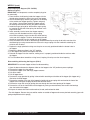
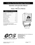
Crathco® Powdered Beverage Dispensers
Service Manual
for
PIC 1, 2, 3, 4, 5, 6
PSD 1, 2, 3, 4, 5, 6
PIC 23A, PIC33A, PIC43A, PIC5W
TABLE
OF
CONTENTS
Warning Labels....................................... 2
Installation.............................................. 4
Start up Procedures................................. 4
How To Dispense Cappuccino.................. 5
Adjustments............................................ 5
Cleaning.................................................. 7
Preventative Maintenance ..................... 11
Service
Light Bulbs................................... 12
Draining the Tank .......................12
Shipment Preparation .................12
Whipper Motors .........................13
Dump Valves .............................. 14
Grommets .................................. 14
Water Tank ............................... 14
Inlet Valve ................................. 16
Thermistor ................................ 17
Auger Motors ............................ 18
Blower Motor ............................ 18
Controller .................................. 18
Heater Relay ......................... ... 18
Transformer .............................. 18
Soluble Conversion .................. 19
Troubleshooting..................................... 20
Exploded Views......................................22
Wiring Diagram............................. ........50
Prior authorization must be obtained from
Grindmaster Corporation™ for all warranty claims.
PIC 2
PIC 1
PIC 5
PIC 33A
PIC 6
Grindmaster Corporation™
4003 Collins Lane
Louisville, Kentucky 40245 USA
(502) 425-4776
(800) 695-4500 (USA and Canada only)
(800) 568-5715 (Technical Service only)
FAX: (502) 425-4664
www.grindmaster.com
© Grindmaster Corporation™, 1996
PRINTED IN USA
0807 Form # CC-302-20
Part # 62780
Warning Labels
The following warning labels were on your dispenser when it was shipped from the factory. They should remain on
your dispenser in good, readable condition at all times. If one of your labels is missing or damaged, order a replacement label immediately.
Part #62981 (PIC 5-6) - Located on the upper splash panel on the front of the dispenser
WARNING
Contents can cause
severe burns if
handled improperly.
ADVER
AD
VERTENCIA
TENCIA
Contenidos pueden causar
quemaduras severas si el
uso es inadecuado.
AVER
VERTISSEMENT
TISSEMENT
Contenu peut provoquer
des brûlures grâves si il est
manipulé incorrectement.
PN# 62981
Part #61321 (PIC 1-4) - Located behind the drip pan on the front of the dispenser
WARNING: Risk of electric shock. Disconnect from power before servicing.
Hot parts and surfaces inside and outside machine may cause burns. Tank drain
hose inside machine dispenses very hot water. Will cause burns and/or personal
injury. Must have five gallon heat resistant container to catch hot water. Hot water
may splash. Do not attempt to stop hot water once it begins flowing. Replace plug
and clamp prior to refilling tank.
Part #100268 (PIC 5-6) - Located behind the drip pan on the front of the dispenser
Page 2
Crathco® Powdered Beverage Dispensers
Warning Labels (cont.)
Part #61319, Located on the outside on the back of the dispenser
Part #61326, Located on the outside on the left of the dispenser
Part #61325, Located on the drain hose inside the dispenser
Crathco® Powdered Beverage Dispensers
Page 3
Installation
Water Inlet Connection
The following is required for water hook-up:
1. A quick disconnect water connection or enough coiled tubing so the machine can be moved for cleaning
underneath. (required for NSF approved water hook-up)
2. A 1/4" male flare adapter is provided (packed inside the drain tray) to be attached by the installer to the
back of the machine for hook-up to water supply.
3. Installation to a water filter system is required to prevent lime and scale build up in the machine.
4. Water pipe connections and fixtures directly connected to potable water supply shall be sized, installed, and
maintained in accordance with Federal, State, and Local codes. (required for NSF approved water hook-up)
5. Equipment is to be installed with adequate backflow protection to comply with applicable Federal, State,
and local codes. (required for NSF approved water hook-up)
Start-up Procedure for Standard Units
NOTE: NSF requires installation of 4” legs for PIC 2,3,4,5,6.
1.
2.
3.
4.
Install drip tray in front of machine.
Connect the 1/4" male flare fitting to the inlet valve on the back of the machine.
Flush the water line to purge any debris from the supply line.
Connect a 1/4" water line to the 1/4" male flare connection and turn the water supply on.
a. Minimum water pressure to the machine: 20 psi
b. Maximum water pressure to the machine: 100 psi
5. Plug the power cord into a proper electrical outlet.
6. Turn the power switch to the “ON” position and allow the water tank to fill. The machine will make a subtle
hissing sound when this occurs. Allow 3-4 minutes (5 minutes for PIC 5 or PIC 6) for fill time depending on inlet
water pressure.
NOTE: If water supply is allowed to run dry, watchdog timer circuit may disable fill circuit. If this occurs, ensure
adequate water supply for machine, then reset machine by turning power switch “OFF” for 1 second and then
turning the power switch back “ON”.
NOTE: Watchdog timer might engage on initial fill on PIC 5 and PIC 6.
7. After the water tank has filled, allow 15-45 minutes (45-60 minutes for PIC 5/6) for the water to reach
operating temperature. (Green ready light will illuminate when tank is up to preset temperature.)
8. Remove the powder hoppers, rotate the dispense elbow to the “up” position, and fill with desired powder product.
IMPORTANT: Check to make sure that the auger inside the hopper is correctly installed prior to
filling. Reinstall powder hoppers. Turn dispense elbow down toward the mixing funnel.
9. Peel protective film off photo merchandiser cover. (Install graphic if needed)
10. Install flavor decals as needed. (Place one on each hopper, and place the corresponding decal on the
dispense section of the front door of the unit)
POWER CORD TABLE
Models
Standard
Models
Q
Z*
Volts
120V
120V
120V
120/208-240
208-240
Watts
1400W
1650W
1650W
2500W
2500W
Phase
Single
Phase
60Hz
Supply Cord
14-3
14-3
12-3
12-4
12-4
Attachment Plug
5-15
5-15
5-20
L14-20
L14-20
Agency
UL,
UL,
UL,
UL,
UL,
CUL,
NSF
CUL,
CUL,
CUL,
NSF
NSF
NSF
NSF
* For Z model neutral is not required.
Start-Up Procedures for Pump Units (PIC 2P & PIC 3P only)
NOTE: Pump units are not designed to be plumbed to pressurized water source.
1. Place a five gallon water container within 3 feet vertically and 2 feet horizontally of the machine.
2. Drop the hose at the rear of the machine into the water container (The hose should extend to approximately
1” from the bottom of the water container.)
Page 4
Crathco® Powdered Beverage Dispensers
Installation (cont.)
Start-Up Procedures for Pump Units (PIC 2P & PIC 3P only) (cont.)
NOTE: Do not let the end of the hose touch the bottom of the container. Shorten the hose if necessary. If you
need a longer hose, remove the back access panel, unclamp existing hose, replace with longer hose and
replace clamp.
3. Proceed with fifth step under Start Up for Standard Units.
How to Dispense a Cup of Cappuccino
On models with manual dispense switches (Refer to serial tag to verify model number of your machine)
1. Place cup under the selected drink dispense nozzle.
2. Push and hold the appropriate switch on the touchpad until cup is 2/3 full and then release switch.
On models with portion control (single portion or 3 portion per head): (optional on PIC 2, 3, & 4 only)
1. Place cup under the selected drink dispense nozzle.
2. Push appropriate switch on the touch pad, then release to dispense one preset serving. (see Portion
Control Adjustment to set portion size)
NOTE: Portion may be cancelled by push and release of the switch during dispensing.
Cup must rest flat on tray with a 1/4” (6 mm) clearance between cup and spout. Contents can
CAUTION:
cause severe burns if handled improperly.
Adjustments
Portion Adjustment
If machine is a manual dispense, there are no portion control adjustments to be made. (Please refer to serial tag to
reference model number.)
SETTING SINGLE PORTION CONTROL
1. Place a cup under the selected drink dispense nozzle.
2. Press and hold the dispense switch.
3. After a 10 second time delay, the machine is triggered into program mode and will begin dispensing.
4. Continue pressing the button until cup is approximately 2/3 full, then release the switch to prevent overfill.
The elapsed portion dispense time is saved to memory and will remain until the dispense switch is
reprogrammed.
5. Check the portion size by placing an empty cup under the desired dispense nozzle, then press and release
the dispense switch. The machine will dispense the preprogrammed portion size.
6. If the portion size is incorrect, repeat above steps until the desired portion size is achieved. Each dispense
switch needs to be set separately.
SETTING THREE PORTION SIZES PER HEAD (optional on PIC 2/3/4 only)
1. Place a cup under the selected drink dispense nozzle.
2. Press and hold the size button on the touch pad that you wish to program or set. (Hold button throughout
entire procedure.)
3. Press and release the manual (top-off) button. After releasing the manual (top-off) button, the 10-second
delay is activated.
4. Continue pressing the size button until cup is approximately 2/3 full, then release the switch to prevent
overfill. The elapsed portion dispense time is saved to memory and will remain until the dispense switch is
reprogrammed.
5. Check the portion size by placing an empty cup under the desired dispense nozzle, then press and release
the dispense switch. The machine will dispense the preprogrammed portion size.
6. If the portion size is incorrect, repeat above steps until the desired portion size is achieved. Each portion size for
each head needs to be set separately.
Crathco® Powdered Beverage Dispensers
Page 5
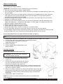
Thermostat Adjustment
NOTE: The thermostat range is approximately 160°F to 200°F. The tank temperature is factory set at 180°F,
making the beverage temperature slightly lower than 180°F.
1.
2.
3.
4.
5.
Unplug machine.
Remove the drip tray.
Remove the upper splash panel on the front of the machine by removing the four Phillips head screws.
Locate the thermostat adjustment dial on the control board(s).
To adjust the temperature of the water being dispensed, turn the adjustment dial on the large* control
board. (Turn clockwise to increase the water temperature or counterclockwise to decrease the water
temperature)
NOTE: It will take time for the water tank temperature to reach its adjusted temperature setpoint.
CAUTION: Do not force the adjustment dial beyond its 270° of rotation or damage to the control board may occur.
*NOTE: PIC 4, 5, and 6 have a second controller. The temperature dial on the right hand board is not active on
this board.
PIC 1 and PIC 4 (Right Head)
Control Board
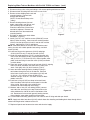
Drink Strength Adjustment
(Refer to Figure A and B)
Tools Required: #2 Phillips Screwdriver
Warning: Risk of Electric Shock! Always turn
off power to machine while servicing or
making internal adjustments to machine.
1. Dispense a drink to determine if drink is too
strong or too weak.
2. Turn off power to machine at power switch.
3. Remove upper front splash cover below
dispense heads in front of machine.
4. Using a flat head screwdriver, adjust individual
dispense heads by rotating appropriate
Figure A Operates PIC and right head on PIC4.
adjustment knob. Turn on power to machine and
Thermostat dial on this board is not used on PIC4.
dispense a drink to determine if drink
strength is acceptable. If drink is not
CONTROL BOARD FOR PIC2/3/4/5/6
acceptable, turn off power to machine
and repeat adjustment steps until
desired drink strength is achieved.
Note: Clockwise rotation will result in a
stronger drink and counterclockwise will result
in a weaker drink.
Note: Water flow rate is factory preset at
approximately 0.80 ounces per second.
1
2
3
1
2
3
1
2
3
1
2
3
1
2
3
Figure B One controller used for PIC2, PIC3.
Remote
Auger
Jumper
Position
Page 6
On-Board
Auger
Jumper
Position
One (Fig A) controller and one (Fig B) controller used for PIC4.
Two controllers used for PIC43, PIC5, PIC6.
Thermostat dial is not used on PIC43, PIC5, PIC6 right controller.
On Right Controller: Left dial operates #4 head, middle dial
operates #5 head, and right dial operates #6 head.
Crathco® Powdered Beverage Dispensers
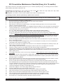
Drink Strength Adjustment for Model PIC3E or PIC33AE
when equipped with remote adjust knobs behind drip tray (Refer to Figure C)
1. Dispense a drink to determine if drink is too strong or too weak.
2. Remove drip tray.
3. Using a flat head screwdriver, adjust individual dispense heads by rotating
appropriate adjustment knob. Clockwise rotation will result in a stronger
drink and counterclockwise rotation will result in a weaker drink.
4. Dispense a drink to determine if drink strength is acceptable,
repeat adjustment steps until desired drink strength is achieved.
NOTE: Water flow rate is factory preset at approximately 24mL (0.80 ounces)
per second.
Figure C
Drink Strength Adjustment for Model PIC2J & PIC3J (Refer to Figure D)
Tool required: #2 Flat Head screwdriver
1. Dispense a drink to determine if drink is too strong, weak or if portion size is correct.
2. Turn off power to machine at power switch.
3. Drink strength and portion size controls will be
found behind the drain tray. (Refer to Figure D) For
portion size adjustment, turn dial clockwise to
increase dispense volume. To decrease volume
turn dial counterclockwise. For drink strength
adjustment turn dial clockwise to increase drink
strength. To decrease strength turn dial
counterclockwise. Turn on power to machine and
PORTION SIZE ADJUSTMENT
dispense a drink to determine if drink strength or
TURN DIAL CLOCKWISE TO
INCREASE DISPENSE
VOLUME
portion is acceptable. If drink strength or portion is
COUNTERCLOCKWISE TO
DECREASE DISPENSE
not acceptable, turn off power to machine and
VOLUME
repeat adjustment steps until desired drink strength
or portion is achieved.
Note: Clockwise rotation will result in a stronger drink and
DRINK STRENGTH
ADJUSTMENT
counterclockwise will result in a weaker drink.
TURN DIAL CLOCKWISE TO
INCREASE DRINK STRENGTH
Note: Water flow rate is factory preset at approximately
COUNTERCLOCKWISE TO
DECREASE STRENGTH
0.80 ounces per second.
Figure D
* To adjust flow rate, remove left side upper panel. Use flat
head screwdriver and turn knob on respective dump valve.
WARNING: Do not adjust flow rate above the factory setting to prevent funnel overflow.
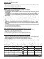
Cleaning
CAUTION: When cleaning the unit, do not use cleansers,
liquid
bleach, powders or any other substance that contains
chlorine. These products promote corrosion of stainless steel
and plastic parts. Use of these products will void the warranty.
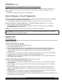
Water Inlet Fitting
Mixing Funnel Shroud
Water Inlet Pipe
Funnel O-Ring
DAILY
1. Empty the drip pan as needed and wash daily in a solution
of dish detergent.
2. Rinse out the whipper chambers by placing the rinse
switch (located on the right of the dispensing valves when
the door is open) in the “ON” position. Dispense one to
two cups until the water is clean. Short bursts of
dispensing may also help clean the chambers more
effectively. When completed, return the rinse switch to the
“OFF” position.
3. Remove the hoppers and refill with product.
Crathco® Powdered Beverage Dispensers
Mixing Funnel
Whipper Chamber
Whipper Base
Motor Shaft
Whipper Base Seal
Whipper O-Ring
Whipper Blade
Dispense Nozzle
Figure E
Page 7
WEEKLY
Removing and Cleaning the Chambers
1. Open the door and remove the mixing funnel shroud by pulling forward while turning 1/4 turn to the right.
Lift off and remove.
2. Remove the mixing funnel by lifting the neck of the funnel out of the whipper chamber, then tilt
counterclockwise. With one hand on the water inlet fitting on the back panel, pull the funnel out of the
white ring.
3. Remove the whipper chamber by rotating it 1/8 of a turn clockwise, then pull to remove.
4. Remove dispense nozzle from whipper chamber by pulling it apart.
5. Remove the whipper blade by grasping the whipper blade with two fingers and firmly pulling to remove.
6. Remove the o-ring on the whipper shaft near the whipper and wipe the motor shaft with a clean towel.
7. All parts in contact with food must be washed, rinsed, sanitized and air-dried.
! CAUTION: Do not wash parts in dishwasher. Dishwashers will cause damage to parts.
To Reassemble
1. Replace the o-ring onto the whipper shaft.
2. Replace the whipper blade by aligning the flat side inside the blade with the flat side of the motor shaft.
Push blade firmly onto shaft.
3. Press dispense nozzle into whipper chamber.
4. Replace the whipper chamber by positioning the medium sized opening up and tilting 1/8 of a turn
clockwise. Put the whipper chamber over the whipper blade and turn counterclockwise until it locks
into place.
5. Replace the mixing funnel by positioning the large opening up and tilting it slightly counterclockwise.
Lubricate the o-ring on the water inlet pipe with a film of food grade lubricant. Insert the water inlet
pipe into the water inlet fitting on the back panel, then rotate the funnel to the right until the neck of the
funnel seats inside the whipper chamber opening.
6. Replace the shroud by placing it on the mixing funnel with the opening to the right. Turn the shroud to
the left until the opening in the shroud rests inside the opening in the back panel.
7. If shroud doesn’t rest inside the opening on the front panel, push in or lift up on the funnel.
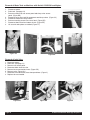
Disassembling & Cleaning the Hoppers (PIC 1/2/3/5/6)
IMPORTANT: Do not wash hopper without first disassembling.
1. Open the door and rotate the dispense elbow on the hopper
to the “UP” position to prevent spillage. (Figure F)
2. Remove the hopper from the cabinet.
3. Remove the hopper cover and empty hopper contents.
4. Pull off the elbow.
5. Remove the auger pinwheel by pulling it forward while
stretching out the sides of the hopper. (Figure G)
6. Remove the drivelink and washer at the rear of the hopper
by holding the auger spring with one hand at the front of the
hopper while turning the drivelink clockwise with the other
hand. (Figure H)
7. Remove the auger spring and auger spring drive shaft by
pulling them out through the lower front opening of the
hopper.
8. Remove the palnut at the rear of the hopper by turning it
counterclockwise, then remove the drive shaft bearing
from the inside of the hopper.
9. All parts in contact with food must be washed, rinsed,
sanitized and air-dried.
Page 8
Figure F
Figure G
Figure H
Crathco® Powdered Beverage Dispensers
WEEKLY (cont.)
Reassembling the Hoppers (PIC 1/2/3/5/6)
(Refer to Figure I)
IMPORTANT: All components must be completely dry prior
to reassembly.
1. Place the drive shaft bearing inside the hopper with the
threads going through the hole in the rear of the hopper.
2. Secure the bearing by attaching the palnut to the bearing
at the outside rear hopper opening. Tighten using only
your fingers. Use one hand inside the hopper to push
the bearing outward while turning the palnut clockwise.
3. Install the auger spring drive shaft and the auger spring
by inserting the flat end of the spring into the hole in the
auger drive shaft.
4. Insert assembly into the lower front hopper opening,
making sure the threaded end of the auger spring
Figure I
drive shaft completely inserts into the drive shaft bearing
in the rear of the hopper. The drive shaft bearing threads
should be accessible from the outside rear of the hopper.
5. Place the washer over the drive shaft bearing threads followed by securing the drivelink onto the drive
shaft bearing by turning counterclockwise. Secure the auger spring with one hand while attaching the
drivelink with the other.
6. Replace the auger pinwheel making sure the pins are securely positioned inside the locator holes in
the hopper.
7. Replace the dispense elbow in the “UP” position.
8. Fill the hopper with product and replace the cover.
9. Reinstall the hopper into the machine; making sure it is properly positioned inside the notches under
the hopper.
10. Turn the elbow down toward the mixing funnel, keeping it lined up over the funnel opening.
Disassembling & Cleaning the Hoppers (PIC 4)
IMPORTANT: Do not wash hopper without first disassembling.
1. Open the door and rotate the dispense elbow on the hopper to the “UP” position to prevent spillage.
2. Remove the hopper from the cabinet.
3. Remove the hopper cover and empty hopper contents.
4. Pull off the elbow.
5. Pull off hopper base.
6. Remove the auger pinwheel by pulling it forward while stretching out the sides of the hopper (thin hopper only).
*See below for wide hopper.
7. Remove the coupling at the rear of the hopper by holding the auger spring with one hand at the front of the
hopper while turning the coupling clockwise with the other hand.
8. Remove the auger with o-ring by pulling them out through the lower front opening of the hopper.
9. Remove the nuts at the front and rear of the hopper by turning counterclockwise, then remove the bearings
from the inside of the hopper.
10. All parts in contact with food must be washed, rinsed, sanitized and air dried.
* For wide hoppers: Remove wing nut and flat washer on outside of hopper and remove pinwheel assembly (gear with
spring and pinwheel with 2 springs)
Crathco® Powdered Beverage Dispensers
Page 9
Weekly Cleaning (cont.)
Reassembling the Hoppers (PIC 4)
IMPORTANT: All components must be completely dry prior to reassembly.
1. Place the bearings inside the hopper in proper position.
2. Secure the bearings by attaching the nuts to the bearings at the outside rear hopper opening. Tighten using
only your fingers.
3. Insert auger into the lower front hopper opening, making sure the threaded end of the auger spring drive
shaft completely inserts into the rear bearing in the rear of the hopper. The auger threads should be
accessible from the outside rear of the hopper.
4. Secure the coupling onto the auger by turning counterclockwise. Secure the auger with one hand while
attaching the coupling with the other.
5. Replace the auger pinwheel making sure the pins are securely positioned inside the locator holes in the
hopper (this hopper only). * See below for wide hopper. For either hopper, turn coupling and make sure
pinwheel in properly installed and turns freely.
6. Replace the dispense elbow in the “UP” position.
7. Fill the hopper with product and replace the cover.
8. Reinstall the hopper into the machine; making sure it is properly aligned.
9. Turn the elbow down toward the mixing funnel, keeping it lined up over the funnel opening.
* For wide hopper: Replace pinwheel assembly by inserting gear through the pinwheel and inserting threads
through the hopper wall. Insert flat washer on outside and finger-tighten wing nut securely.
Cleaning the Steam Plenum Tray (PIC 2/3/4/5/6 only) (Refer to Figure L)
CAUTION: Do not pour liquid into tray. Failure to comply will damage the dispenser and void the warranty.
1. Rotate dispense elbows on the hoppers to the “up” position and remove hoppers from machine.
2. Remove cover plate inside machine cabinet, located below hoppers.
3. Using a damp towel, wipe powder build up from
inside steam plenum tray.
4. Replace cover plate.
5. Replace hoppers and turn elbows down to the
dispense position.
Quarterly Cleaning
Cleaning the Steam Recovery Plenum Tray
WARNING: Risk of electric shock; Disconnect
from power before servicing!
1. Remove the side access panel (Refer to figure K)
2. Disconnect the flexible vent tube attached to the
Figure J
recovery tray.
3. Remove the two screws which fasten the recovery
tray to the sheetmetal enclosure and remove the
recovery tray through the side access hole.
4. Remove the back access plate (refer to figure L). Disconnect and remove the
flexible vent tube from the blower housing. Carefully remove the flexible vent
tube from the machine's cabinet.
5. Wash, rinse, sanitize, and air dry the recovery tray and hose. Note: A long soft
bristle brush or small cloth towel may be used to clean the internal passage of
the flexible vent tube by pushing it through the tube. Rinse, sanitize and air
dry the tube.
6. Reassemble the parts in reverse order.
NOTE: PIC 5 and PIC 6 contain two ports on the plenum, three flexible tubes
and a barbed tee.
Page 10
Figure K
Figure L
Crathco® Powdered Beverage Dispensers
PIC Preventative Maintenance Checklist (Every 6 to 12 months)
A preventative maintenance visit should be performed every 6 to 12 months, depending on usage. The following procedures should be
performed during a preventative maintenance visit.
Parts Required: One PM parts kit (PIC1 - Qty1 - 62707, PIC2 - Qty2 - 62707 or Qty1 - 60933, PIC3 - Qty1 - 60933, PIC4 - Qty1 - 60933
and Qty1 - 62707, PIC5 - Qty2 - 60933, PIC6 - Qty2 - 60933).
Tools Required: 11/32 nut driver, needle nose pliers, phillips head screwdriver, food grade lubricant.
The following procedures should be performed by a qualified service technician.
1.
2.
3.
4.
5.
6.
7.
8.
9.
10.
11.
12.
13.
14.
15.
16.
17.
18.
19.
20.
21.
22.
23.
24.
25.
26.
WARNING - Risk of electric shock and burns. Disconnect power before servicing. Use care in handling hot liquids.
Document model and serial number of equipment above.
Disconnect unit from power supply and turn power off. Then remove all access panels.
Shut off the water supply valve to the machine.
Open front door of unit and remove product hoppers. Clean hoppers following procedures on the decal on panel behind
hoppers or as stated in instruction manual.
Remove the plenum chamber access panel, if so equipped (located below hoppers on newer units). Wipe out exposed plenum.
Locate the tank drain hose. It is located behind the bottom access panel. It is a white silicone tubing that has a 3/8” stainless
steel barb plug and a black 5/8” hose clamp on it.
PIC 1, 2, 3, and 4: Using a 5 gallon, heat resistant container, route the drain hose into the container.
PIC 5 and 6 contain over 5 gallons of hot water and require a minimum 6 gallon heat resistant container.
Remove the clamp, pinch the tube and remove the plug. Drain all of the water out of the tank into the container (about
3.5 gallons). Warning: the water from the tank is very hot (180°F plus). May cause burns and/or personal injury. Hot water may
splash. Do not attempt to stop flow of hot water once it begins flowing through drain hose. Replace the drain hose plug and
secure the clamp back onto the drain hose. Place the drain hose back inside the machine, to its original location. Carefully
empty the drain bucket. Do not refill the unit at this time. Delime tank if needed.
Remove the mixing funnel shroud and mixing funnel from each chamber. Remove and discard the o-ring on the mixing funnel.
Set the shroud and funnel aside.
Remove each whipper chamber and whipper blade. Check for wear and replace if necessary. Then remove and discard the
small whipper shaft o-rings from each dispense head.
Remove the two screws from each whipper base and save the screws. Discard the old whipper base and slinger washer, and
replace with the new parts in the PM kit.
Clean the whipper motor shaft and clean all dried product in this area under where the whipper base was located.
Install the new slinger washer onto the whipper motor shaft, and up to hopper mounting bracket.
Lubricate inside of whipper base with a food grade lubricant. Then install whipper base over the whipper motor shaft and check
alignment of holes. If alignment is off, rotate base 180° to make sure holes line up. Hold base securely, and carefully
tighten mounting screws.
Check whipper motor shaft to ensure it can turn freely using fingers. If shaft is hard to turn, remove screws, rotate base 180°,
and re-tighten.
Install the new, red, small o-rings, along with the whipper blades, and whipper chambers. Clean the funnel shrouds and funnels.
Install each new funnel o-ring and lubricate. Then install funnel and shroud. When complete, put the plenum chamber access
panel back in place, if so equipped.
Remove plenum through side access hole and remove the plenum hose(s) from the blower to the plenum chamber. Clean the
plenum and either clean or replace the hose(s) (part# 61123, not in kit). Re-install clean parts.
Remove the dump valves located behind side access panels, by loosening the dump valve bracket nuts with the 11/32 nut
driver and lifting bracket up. Then pull dump valve from grommet and then remove the grommets from the tank with needle
nose pliers and discard. Then remove the o-rings from the dump valves and discard. Replace with new tank grommets and new
o-rings for each valve. Re-install the dump valves and secure back onto the tank. Tighten nuts on dump valve bracket.
Locate power supply and verify proper electrical supply to unit.
Find the water supply line. Turn on water supply, and verify adequate water flow.
Turn power supply back on. Then turn main power switch to “on”.
Verify water tank in unit is filling. After the tank is full, verify that the heating cycle has started.
Allow unit to fill and shut off. Check around dump valves and any tubing for signs of water leaks.
Replace all access panels and reinstall hoppers inside the unit. Verify nut on back of hopper is secure.
Verify each dispense head is operating properly and that the settings are correct. Adjust if necessary.
Check for proper product temperature and check mix ration for proper setting, and adjust if necessary.
Review proper care, cleaning and maintenance procedures with store personnel.
Crathco® Powdered Beverage Dispensers
Page 11
Service
Changing the Lightbulb on Models With a Backlit Merchandiser (PIC 1/2/3/4/5/6)
(Refer to Figure M) (Refer to serial tag to verify model number of your machine)
Disconnect machine from branch electrical supply before changing
WARNING:
the lightbulb.
NOTE: PIC2/3/4 uses a F8T5 12" 8 watt replacement bulb. PIC5/6 uses a 22W circular bulb.
1. All: Remove the front merchandiser photo and cover by grasping the edges of the
merchandiser.
2. PIC1: Lift bulb out of socket vertically.
PIC 2/3/4: Remove the old lightbulb by gently turning the lightbulb 1/4 turn to the left and
pulling the bulb from the socket.
PIC5/6: Disconnect cable from bulb and pull bulb from holder.
3. PIC2/3/4: Install the new bulb by lining up the pins on either end of the bulb parallel
with the socket opening.
4. PIC2/3/4: Gently insert both ends of the bulb into the socket and turn the bulb 1/4 turn to the
right until the bulb locks into place.
5. All: Replace the merchandiser photo and cover.
Figure M
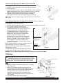
To Prepare for Shipment
Important: Always completely empty water tank and POWDER HOPPERS prior to shipping unit. (See draining the
tank and cleaning the hoppers sections)
NEVER SHIP UNIT WITH POWDER IN HOPPER - THIS WILL CAUSE IRREPARABLE DAMAGE.
Draining the Tank (PIC 2/3/4 )
Always empty the tank before shipping.
NOTE: PIC 1 contains 2 gallons of hot water.
PIC 2, PIC 3 and PIC 4 contain 3-1/2 gallons of hot water.
PIC 5 and PIC 6 contain 5-1/2 gallons of hot water.
Draining of tank should be performed by a qualified service technician. The tank contains
WARNING:
very hot water. May cause severe burns.
1.
2.
3.
4.
Prepare a heat resistant container to drain the tank water into.
Unplug the machine.
Remove the drain tray and front access panel. (Figure N)
Locate the silicone drain hose on the left side wall. Put the end of the drain hose into the container. Secure
the end of the drain hose (i.e. with tape) into the container. (Figure O)
5. Remove the hose clamp and plug. (Figure P)
6. Allow the tank to drain completely.
NOTE: It may be necessary to pinch the hose and stop the water before container is full. Carefully
re-install plug, then empty container. Repeat steps 4-6 to completely drain tank.
Figure N
Page 12
Figure O
Figure P
Crathco® Powdered Beverage Dispensers
Draining the Tank (PIC 2/3/4 ) (cont.)
7. Once the tank is empty, securely replace the plug and clamp on the end of the hose. Reposition the drain
hose inside the hose clip on the left side wall.
8. Reassemble the front access panel and drain tray.
Purging Machine of All Water for Shipment in Cold Areas
WARNING: This procedure should be performed by a qualified service technician.
1. Turn the power switch to the "OFF" position.
2. Drain the water tank (refer to instructions on page 12). Do not replace the drain hose plug and clamp until
further instructed.
3. Turn the power switch to the "ON" position. The ready light should turn itself "ON" within 12 seconds. The
12 second delay signals that the heating element has been disabled due to the lack of water in the tank
after it is drained.
IMPORTANT: If the ready light does not turn itself "ON" within 12 seconds, turn the power "OFF" to avoid
burning out the heating element.
4. Listen for the inlet valve to energize. To purge the inlet valve and water inlet tube, apply 10-20 psi
compressed air to the inlet valve connection for 10 to 20 seconds while the inlet valve is energized.
NOTE: Do not energize the inlet valve for more than 5 minutes at a time. Otherwise, the watchdog timer will
disable the inlet valve. If this occurs, reset the machine by flipping the power switch “OFF” then “ON”.
5. After the inlet valve and water inlet tube are purged, purge the dump valves and dispense lines. While
applying 10-20 psi compressed air to the inlet valve connection, press and hold each dispense button for
1-2 seconds.
6. Turn the power switch to the “OFF” position. Replace the drain hose plug and clamp. Reposition the drain
hose inside the hose clip on the left side wall.
7. Reassemble the front access panel and drain tray.
Replacing Whipper Motors on Machines Manufactured Prior to Fall 1998:
1. Left motor may be changed with 61116-01 (round motor) if you install a single pole switch
(part # 61847) in place of the existing power switch.
2. Middle motor may be changed with 61116-01 directly.
3. Right motor can only be changed with 61116R (Oval (double-D) shaped motor).
Replacing Whipper Motors on Machines Manufactured After Fall 1998:
1. Place motor in mounting location, install lock washers and loosely tighten acorn nuts on motor mounting
studs. Hold motor while shaft is centered inside hole then tighten nuts securely.
2. Install white slinger washer over the motor shaft and up to hopper mounting bracket.
3. Lubricate inside of whipper base then install over the motor shaft and check alignment of holes. If alignment
is off, rotate base 180° to make sure holes line up. Hold base securely, and carefully tighten mounting
screws.
4. Check the motor shaft to ensure it can turn freely with fingers. If shaft is still hard to turn, reposition motor
and repeat.
120V Whipper Motor Replacement Kit # 62528
230V Whipper Motor Replacement Kit # 62530
Quantity
Part #
Description
Quantity
Part #
Description
1
61523
Whipper Base
Assembly
1
61523
Whipper Base
Assembly
1
61116-01 or
61867
62529
Motor, Whipper,
120V
Instruction Sheet
1
61117-01
1
62529
Motor, Whipper,
230V
Instruction Sheet
1
Crathco® Powdered Beverage Dispensers
Page 13
Removal of Whipper Motor(s):
1.
2.
3.
4.
5.
6.
7.
Disconnect power.
Remove front and side access panels.
Remove chamber.
Remove whipper base. (Figure Q)
Remove motor nuts and pull motor out of slot. (Figure R, S)
Disconnect wire connection. (Figure T)
Replace motor as needed.
Figure Q
Figure R
Figure S
Figure T
Replacing Dump Valves, Dump Valve O-rings, and/or Tank Grommets
1. Remove the dump valves located behind side access panels, by loosening
the dump valve bracket nuts with 11/32 nut driver and lifting bracket up.
(Figure U, V)
2. Pull dump valve from grommet and then remove the grommets from the
tank with needle nose pliers and discard. (Figure W)
3. Remove the o-rings from the dump valves and discard. Replace with new
tank grommets and new o-rings for each valve. (Figure X)
4. Re-install the dump valves and secure back onto the tank.
5. Tighten nuts on dump valve bracket.
Figure U
Figure V
Figure W
Figure X
Replacing Water Tank on Machines with Serial # 339304 and Lower:
(Refer to Figures Y, Z, AA)
1. Switch off and unplug unit, disconnect from water supply, and drain tank completely.
2. Remove top of cabinet, left side and rear access panels.
3. Disconnect tank ground, heating element, thermal probe, water probe and hi-level thermostat wires and
vent tubing in top of unit.
Page 14
Crathco® Powdered Beverage Dispensers
Replacing Water Tank on Machines with Serial # 339304 and Lower: (cont.)
4. Disconnect dump valve wiring and tubing in left access opening and remove valves.
5. Disconnect tank fill tubing from inlet valve in rear of unit.
6. Remove screws holding water tank and
mounting bracket. Remove tank,
bracket and old tubing
(NOTE: Do not discard dump valve
tubing).
7. Remove heating element, thermal
probe, water probe, vent fittings, and
valve retaining clip from old tank.
Examine to determine if these items
need to be replaced. Remove and
discard old hi-level thermostat and
mounting bracket.
Figure Y
8. Drill holes in cabinet per sketch below
and deburr. (Figure Y)
9. Install (3) #8-32 x 3/8" machine screws (07026-07) in new
holes in sides of casing. Lower new tank retaining bracket
(61845) from the top of the unit until it rests on the machine
screws. Add locknuts (71261) and tighten.
NOTE: Instructions above are for units with a stainless steel
casing, for units with a black powder coat casing, use black
screws (61303).
10. Install new dump-valve grommets (61243) and plugs
(61229) (for PIC2 only) in side of new tank (61841).
11. Install new probe grommets (71147), heating element with
new hi-level thermostat (62305), mounting bracket (62238)
and (2) #8-32 x ¼" SS screws (61353), thermal probe, water
probe, and vent fittings in new tank cover (61842) as shown
in sketch below.
Figure Z
12. Place tank gasket (61844) over top of new tank (61841), aligning
holes with studs, and lower new tank cover (61842) over
studs. Bolt tightly with (10) #8-32 locknuts (71261).
13. Lower tank onto retaining bracket, feeding fill fitting in
tank bottom through the hole in the bracket. Bolt tank
to the back of casing with (2) lock washers (61186) and
(2) #8-32 x 3/8" machine screws (07026-07) for
stainless casings, or #8-32 x 3/8" black screws for black
powder coat units.
14. Install new o-rings (61365) on dump valves and insert
them into side of tank from the access panel in the side
of the casing. Secure with valve retaining clip,
reconnect all wires and dump valve tubing.
15. Measure and cut new 29" vent tubing (05826), connect
one end to the vent fitting in the top of tank and run the
Figure AA
other end down the side of the tank to the bottom of the
unit. Reconnect all wires to tank ground, heating element,
thermal probe, water probe, and hi-level thermostat.
16. Cut and install new tubing (05826) from inlet valve to tank fill fitting and drain per sketch.
NOTE: Apply tank drain hose decal (61325) to drain hose after installing and feeding drain hose through hole in
control mounting bracket in bottom of the unit.
17. Replace all panels and reconnect to water and electrical supply.
Crathco® Powdered Beverage Dispensers
Page 15
Removal of Water Tank on Machines with Serial # 339305UK and Higher:
1.
2.
3.
4.
5.
6.
7.
8.
Disconnect power.
Drain tank. (see page 12)
Remove machine lid, rear access panel and dump valve access
panel. (Figure BB)
Disconnect wires from tank lid components and dump valves. (Figure CC)
Disconnect hoses from dump valves.
Remove mounting screws from rear of tank. (Figure DD)
Disconnect drain hose from bottom of tank. (Figure EE)
Lift out tank and replace as needed. (Figure FF)
Figure BB
Figure CC
Figure DD
Figure EE
Figure FF
Removal of Inlet Valve
1.
2.
3.
4.
5.
6.
7.
8.
Disconnect power.
Drain tank. (see page 12)
Remove rear access panel.
Disconnect black hose from fan.
Remove two screws and lock nuts. (Figure GG)
Remove valve. (Figure HH)
Disconnect wire connection, hose clamp and hose. (Figure II)
Replace valve as needed.
Figure GG
Page 16
Figure HH
Figure II
Crathco® Powdered Beverage Dispensers
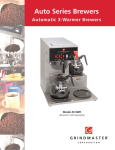
Removal of Thermistor
1.
2.
3.
4.
5.
Disconnect power.
Remove machine lid. (Figure JJ)
Disconnect thermistor wires. (Figure KK)
Lift out thermistor and replace as needed. (Figure LL)
To replace with thermistor, add food grade lubricant. (Figure MM)
Figure JJ
Figure KK
Figure LL
Figure MM
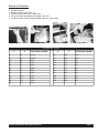
THERMISTOR CURVE
°C
°F
RESISTANCE (OHMS)
°C
°F
RESISTANCE (OHMS)
0
32
16325
60
140
1244
5
41
12697
65
149
1041
10
50
9951
70
158
875
15
59
7856
75
167
740
20
68
6246
80
176
628
25
77
5000
85
185
535
30
86
4028
90
194
458
35
95
3266
95
203
393
40
104
2663
100
212
339
45
113
2185
105
221
294
50
122
1802
110
230
255
55
131
1493
Crathco® Powdered Beverage Dispensers
Page 17
Removal of Auger Motor(s)
1.
2.
3.
4.
Disconnect power.
Remove front and side access panels.
Remove hoppers.
Remove three screws and
lock washers. (Figure NN)
5. Pull motor out of slot. (Figure OO)
6. Disconnect wire connection.
7. Replace motor as needed.
Figure NN
Figure OO
Removal of Blower Motor
1.
2.
3.
4.
5.
6.
7.
8.
9.
Disconnect power.
Drain tank. (see page 12)
Remove rear access panel.
Disconnect black hose from fan.
Disconnect hose from inlet valve if needed.
Remove two screws from side.
Remove fan. (Figure PP)
Disconnect wires.
Replace motor as needed.
Figure PP
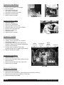
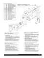
Removal of Controller
1. Disconnect power.
2. Remove front access panels.
3. Carefully remove connectors from controller.
(Do not pull on wires.)
4. Carefully press black clips back and pull out
controller. (Do not pull on controller components pull only on green board.)
5. Carefully remove controller. (Figure QQ)
(Handle controller only on edges of green board.)
6. Replace controller as needed.
Ballast
p/n 61196
Transformer
p/n 61481
Heater
Relay
p/n 61131
Controller
Removal of Heater Relay
1. Disconnect power.
2. Remove front access panels.
3. Remove wires from relay. (Note locations of wires
before removing.)
4. Remove screws and lift out relay. (Figure QQ)
5. Replace relay as needed.
Figure QQ
Removal of Transformer
1.
2.
3.
4.
5.
Disconnect power.
Remove front access panels.
Remove wires from transformer. (Note locations of wires before removing.)
Remove screws and lift out transformer. (Figure QQ)
Replace transformer as needed.
Page 18
Crathco® Powdered Beverage Dispensers
Crathco® Powdered Beverage Dispensers
Page 19
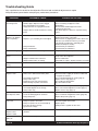
Troubleshooting Guide
Only a qualified service technician should perform Electrical and mechanical adjustments or repairs.
Always disconnect power before attempting any maintenance procedures.
PROBLEM
No powder dispensed
into mixing funnel
PROBABLE CAUSE
•
•
•
•
Rinse switch turned to “RINSE ON” position
Powder hopper dispense outlet clogged
No or low powder level in hopper
Hopper drivelink not engaged with motor
• Hopper elbow is not directed into the mixing
funnel
Machine will not
dispense any product
(water or powder)
Product not whipping
• Power turned “OFF” to machine
CORRECTIVE ACTION
•
•
•
•
Flip rinse switch to “RINSE OFF” position
Refer to Cleaning of Hoppers section
Refill hopper
Remove and reinstall hopper and ensure
engagement with motor
• Turn down dispense elbow; line it up with mixing
funnel
• Faulty transformer
• Faulty control board
• Ensure power switch is in “ON” position, machine is
plugged in and water is turned on
• Reset machine by flipping power switch “OFF” then
“ON” once (the maximum run time per head is
limited to 40 seconds before watchdog timer
disables the dispense heads)
• Contact factory for assistance
• Contact factory for assistance
• Whipper blade broken or missing
• Verify blade is in place. Replace if broken or missing
• Dispense cycle watchdog timer has tripped
Water overflows mixing • Water flow too fast
funnel
• Whipper chamber outlet restricted
• Whipper blade broken or missing
• Contact factory for assistance
Dump valves to be adjusted
• Remove obstruction
• Verify blade is in place. Replace if broken or missing
Drink is too weak or
strong
Refer to Drink Strength Adjustment section (page 6)
Drink is too hot or cold
Refer to Thermostat Adjustment section (page 6)
No hot water from
dispense head
• Thermostat not adjusted
• Faulty heater relay
• Dump tube from water tank is kinked
• Water shorting out probe connections
• Refer to Controller Diagnostics section (page 20)
• Ensure that water supply to machine is “ON” and
reset power to machine
• See Thermostat Adjustment section (page 6)
• Replace heater relay (page 18)
• Check tubing for obstructions
• Dry connections on tank
Water tank boils water
• Check for flashing lights on controller
• Thermostat adjustment set too high
• Faulty heater relay
• Refer to Controller Diagnostics section (page 20)
• Refer to Thermostat Adjustment section (page 6)
• Replace heater relay (page 18)
No water dispensed
from dispense nozzle
• Water supply to machine turned “OFF”
• Check for flashing lights on controller
• Faulty dump valve
• Turn “ON” water supply to machine
• Refer to Controller Diagnostics section (page 20)
• Replace dump valve (page 14)
Water overflows from
water tank
•
•
•
•
•
•
•
•
Machine inadvertently
dispenses from
dispense heads
• Wet wiring connections on harness or
controller
• Allow connections to dry
Drink is cold and ready
light is on
• Check for flashing lights on controller
• Refer to Controller Diagnostics section (page 20)
Page 20
• Check for flashing lights on controller
• Water level in tank is below water probe
Leaky inlet water valve
Faulty level probe connection
Faulty level probe due to mineral build-up
Inlet water pressure too high
(greater than 120 psi)
Replace inlet water valve
Check level probe connections
Replace probe
Install pressure regulator to water inlet
Crathco® Powdered Beverage Dispensers
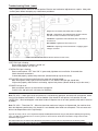
Troubleshooting Guide (cont.)
Only a qualified service technician should perform Electrical and mechanical adjustments or repairs. Always disconnect power before attempting any maintenance procedures.
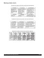
Diagnostics for all PIC2, PIC3, PIC4, PIC5, and PIC6’s:
WTR FAIL = Light flashes when watchdog timer disables machine
after 300 seconds of continuous inlet valve operation.
THERM FAIL = Light flashes when thermistor fails or thermistor is
disconnected.
WTR HEATER = Light flashes when heater is on.
POWER OK = Light stays on when transformer is supplying proper
voltage to controller.
FRONT VIEW OF CONTROL BOARD (BEHIND FRONT ACCESS PLATE)
If WTR FAIL light is flashing:
Ensure water supply to machine is turned “on”.
Reset machine power “off” then “on”.
If THERM FAIL light is flashing:
Reset machine power “OFF” then “ON”. If green ready light does not turn off after 10 seconds then:
Check thermistor connections.
If connected properly, replace faulty thermistor. (Mineral build-up may be the cause.)
WTR HEATER light will flash on and off when the water tank is being heated:
Note: When green “ready” light on front of machine is “Off” WATER HEATER light should flash.
If light works properly and machine is not heating, replace faulty heater. (Mineral build-up may be the cause.)
If POWER OK light is off:
Make sure power switch is on and machine is plugged in.
If switch is on, and light is off, call factory for assistance.
Note: PIC 4/5/6 - If water gets cut off to machine for 5 minutes during operation, tank water will not replenish, heater
circuit will be disabled, and heads #1-3 will be disabled. Other heads will still operate. Left controller will read
“WATER FAIL”. What could happen is that other heads will dispense low or no water (possibly cold) and full amounts
of powder.
Note: PIC 4/5/6 - “Thermistor Fail” - When the thermistor reads out of range or is disconnected, the machine shuts
down the dispensing and heating. Only heads #1-3 are disabled, other heads can still operate. This can cause cold
drinks to be dispensed out of the right head(s).
If you still need help, call our service department at (800) 695-4500 (USA and Canada only) or (502) 425-4776 (Monday through Friday,
8 am - 6 pm EST) or an authorized service center in your area. Please have the model and serial numbers ready so that accurate
information may be given.
Prior authorization must be obtained from Grindmaster Corporation’s Technical Services Department for all warranty claims.
Crathco® Powdered Beverage Dispensers
Page 21
PIC 1 Chassis Parts
(units with serial numbers beginning with “L”)
63493
Page 22
63493
63493
Crathco® Powdered Beverage Dispensers
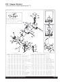
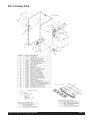
PIC 1 Hopper Bracket
(units with serial numbers beginning with “L”)
Crathco® Powdered Beverage Dispensers
Page 23
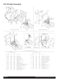
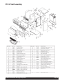
PIC 1 Door Assembly
(units with serial numbers beginning with “L”)
Page 24
Crathco® Powdered Beverage Dispensers
PIC 1 Tank Assembly
(units with serial numbers beginning with “L” or “T”)
( * ) ( *** )
(*) = 71610 REPAIR KIT FOR DUMP VALVE
(***) = 61365 DUMP VALVE O-RING
Crathco® Powdered Beverage Dispensers
Page 25
PIC 1 Chassis Parts
(units with serial numbers beginning with “T”)
63493
Page 26
63493
63493
Crathco® Powdered Beverage Dispensers
PIC 1 Hopper Bracket
(units with serial numbers beginning with “T”)
$2!7).'Ĥ'
%80,/$%$Ĥ6)%7Ĥ
(/4
$
#/,
0!24Ĥ.5-"%23
6/,4% 6/,4* 6/,41 6/,4Ĥ*
./4% ./ 6/,4
.!
.!
.!
.!
.!
.!
.!
.!
.!
$%3#2)04)/.
37)4#(Ĥ30$4Ĥ4/'',%
,!"%,Ĥ(/4Ĥ/2Ĥ#/,$
(!2.%33Ĥ!-"Ĥ4%-0
/04)/.!,Ĥ!-")%.4Ĥ4%-0%2!452%
3%
2). &
/&
!$
2%
/.
0/
7%
9
/.
2
/.
&
/&
6
*
!$
,)'
0/
7%
9
(4
2
/.
/.
/&
&
/.
&
/&
0!24Ĥ.5-"%23
6 6
1
*
0!24Ĥ.5-"%23
6
%
2%
./4% ./ 6/,4
$%3#2)04)/.
./4%
./
"2!#+%4Ĥ(/00%2Ĥ-/5.4
#(!-"%2Ĥ7()00%2
",!$%Ĥ7()00%2Ĥ&/52
7!3(%2Ĥ3,).'%2
3%!,Ĥ,)0ĤĤ)$ĤXĤĤ/$
"!3%Ĥ7()00%2Ĥ3%,&,/#!4).'
0,%.5-Ĥ34%!-Ĥ2%#/6%29
45").'ĤĤĤ)$Ĥ&,%8)",%
/2).'ĤĤ)$ĤXĤĤ/$
&5..%,
%,"/7Ĥ(/00%2
&)44).'Ĥ&5..,Ĥ15)+Ĥ#.#4
30!#%2
3(2/5$Ĥ34%!-Ĥ2%#/6%29
(/00%2Ĥ!33%-",9Ĥ/&Ĥ,"
(/00%2Ĥ!33%-",9Ĥ/&Ĥ,"
-/4/2Ĥ6$#Ĥ!5'%2
37)4#(Ĥ4/'',%Ĥ!Ĥ$034
-/4/2Ĥ7()00%2
,!-0Ĥ'2%%.
,!-0Ĥ2%$
!')4!4/2Ĥ,/7%2Ĥ0).7(%%,
!')4!4/2Ĥ500%2Ĥ0).7(%%,
$%#!,Ĥ0/7%2Ĥ/./&&
$%#!,Ĥ2).3%Ĥ/./&&
$%#!,Ĥ0/7%2Ĥ/.Ĥ
Crathco® Powdered Beverage Dispensers
6/,4
6
%
6
*
.!
.!
6
1
.!
6
*
.!
$%3#2)04)/.
$%#!,Ĥ2%!$9
(/00%2ĤLB
(/00%2ĤLB
!5'%2Ĥ34!.$!2$
,).+Ĥ!5'%2Ĥ$2)6%
$2)6%3(!&4Ĥ!5'%2Ĥ302).'
#/6%2ĤLBĤ(/00%2
302).'Ĥ,72Ĥ0).7(,Ĥ!')42
302).'Ĥ502Ĥ0).7(,Ĥ!')42
"544/.Ĥ2%342)#4/2Ĥ!.',%$
30/54Ĥ03$Ĥ,/.'%2
"%!2).'Ĥ$2)6%3(!&4
0!,.54ĤĤ5.#
7!3(%2Ĥ&,!4ĤĤ3!%Ĥ33
(!2.%33Ĥ(/00%2Ĥ"2!#+%4
0,5'Ĥ!-")%.4Ĥ37)4#(Ĥ(/,%
"%!2).'ĤĤ)$ĤXĤĤ/$
45").'ĤĤ)$ĤĤ7!,,
#/6%2ĤLBĤ(/00%2
#,!-0ĤĤ)$Ĥ(/3%
3%!,Ĥ#,/3%$Ĥ#%,,Ĥ&/!3%!,Ĥ(/00%2Ĥ"+4
342!).Ĥ2%,)%&Ĥ(%9#/Ĥ
3#2%7ĤĤ+.52,
/2).'ĤĤXĤ
37)4#(Ĥ3034Ĥ2).3%
Page 27
PIC 1 Door Assembly
(units with serial numbers beginning with “T”)
63097
Page 28
63097
63097
Crathco® Powdered Beverage Dispensers
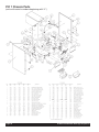
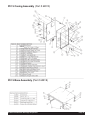
PIC 2/3 Chassis Parts
Crathco® Powdered Beverage Dispensers
Page 29
PIC 2/3 Hopper Bracket
Page 30
Crathco® Powdered Beverage Dispensers
PIC 2/3 Tank Assembly
Crathco® Powdered Beverage Dispensers
Page 31
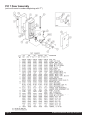
PIC 2/3 Door Assembly
Page 32
Crathco® Powdered Beverage Dispensers
PIC 4 Chassis Parts
63493
Crathco® Powdered Beverage Dispensers
Page 33
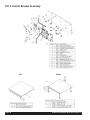
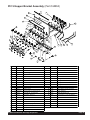
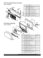
PIC 4 Control Bracket Assembly
Lid
Page 34
Base
Crathco® Powdered Beverage Dispensers
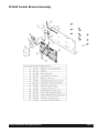
PIC43A Control Bracket Assembly
Crathco® Powdered Beverage Dispensers
Page 35
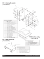
PIC 4 Hopper Bracket
Funnel Whipper
Shroud
Page 36
Crathco® Powdered Beverage Dispensers
PIC 4 Hopper
62639 Hopper Assy 5.5# PIC4 (use for sugar-based powders)
62640 Hopper Assy 11# PIC4 (use for sugar-based powders)
PE 32
63078 Hopper Assy 5.5# PIC4 SOL (use for soluble coffee)
Crathco® Powdered Beverage Dispensers
Page 37
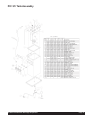
PIC 4 Tank Assembly
,7(012 3$5712 '(6&5,37,21
&RYHU3,&:HOGHG7DQN/LG
3UREH7KHUPLVWRU
(OHPHQW
187137%5$66
(QWHU7LWOH
352%(3,&
767$7+,7(03/,0,7
*5200(76,/,&21(:+7
7XELQJ,'[:/6LOLFRQH
&ODPS+RVH,'+H\FR
(OHPHQW9:
(OHPHQW9:
18766:,7+1</21,16(57
7DQN)LQDO$VVHPEO\
7DQN/LG$VVHPEO\
,7(012 3$5712 '(6&5,37,21
7DQN$VV\3,&
7DQN/LG$VV\9:
*DVNHW3,&:HOGHG7DQN
%UDFNHW7DQN%UDFH7RS3,&
18766:,7+1</21,16(57
7(50,1$/;'(*7$%
3,&:
7DQN$VVHPEO\
'UDLQ)LOO7XELQJ$VVHPEO\
,7(012 3$5712 '(6&5,37,21
7DQN:DWHU3,&
*URPPHW3OXJ3,&XQLWV
*URPPHW'XPS9DOYH
%UDFNHW'XPS9DOYH%UDFH
18766:,7+1</21,16(57
9$/9('8039+'(/752/
+DUQHVV3,&:2SWLRQ
Page 38
,7(012 3$5712 '(6&5,37,21
&ODPS+RVH,'+H\FR
3OXJ%DUE
7XELQJ,'[:/6LOLFRQH
7XELQJ,'[:/6LOLFRQH
0DUNHWLQJVKHHWUHY%
7XELQJ,'[:/6LOLFRQH
(&1-5(
'HFDO7DQN'UDLQ+RVH
Crathco® Powdered Beverage Dispensers
PIC 4 Door Assembly
Crathco® Powdered Beverage Dispensers
Page 39
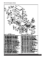
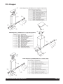
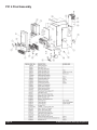
PIC 4 Final Assembly
Page 40
Crathco® Powdered Beverage Dispensers
PIC 5 Casing Assembly (Part # 62813)
63493
PIC 5 Base Assembly (Part # 62819)
Crathco® Powdered Beverage Dispensers
Page 41
PIC 5 Control Bracket Assembly
(Part # 62974)
2
PIC 5 Lid Assembly
(Part # 62810)
1
11
4
6
4
1
3
5
3
12
5
3
2
ITEM NO. PART NO. DESCRIPTION
1
62849
Bracket, Control Mtg PIC5 No Display
2
61338
Terminal Board
3
61800
Controller,Pic 3 Portion
4
61131
Relay,12 vdc Coil
5
61481
Transformer,40VA 24/12S
6
61266
STANDOFF, RVRS EDGEMOUNT
7
10073
Label, Ground Symbol
8
60394
Bushing,Snap-7/8"OD x 3/4"
ITEM NO. PART NO. DESCRIPTION
1
62811
Panel, Lid,
2
61303
Screw, #8 x 3/8 black trilobe
3
61217
Spring, Hopper Retaining
4
62812
Flashing Top PIC5
5
86877
SCRW, #8X1/2 PH TR HD T/AB ZNC
9
61303
Screw, #8 x 3/8 black trilobe
10
61272
SCRW, #8X3/8 PH PN T/B ZNC/GN
11
62890
Harness, Chassis PIC5/6
12
62928
DECAL, CONTROLLER PIC5/6
23
7
3
1
8
13
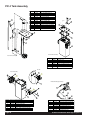
PIC 5 Door Assembly
(Part # 63060)
10
6
11
12
22
Door Assembly
63060 - PIC5
63484 - PIC5W
ITEM NO. PART NO. DESCRIPTION
14
20 21
PLUG HOLE WITH #71138
IF NO HOT WATER
2
ITEM NO. PART NO. DESCRIPTION
1
63482
Door Plastic PIC5W w hole
13
63061
2
62915
Switch, Dispns PIC5/6 No Wafer
14
61327
Decal, Light Replace
3
62884
Door Brkt Wldmt,
15
71129
NUT, 8-32 KEPS SS
4
62904
Cover,PIC5 Graphic
16
60394
Bushing,Snap-7/8"OD x 3/4"
5
62905
Graphic,PIC5
17
61272
SCRW, #8X3/8 PH PN T/B ZNC/GN
6
62856
Decal, 2/3 Full PIC5/6
18
61187
Washer, #8 Star Lock
7
62847
Panel, Dispense Switch Cvr,
19
70635
TERMINAL, 1/4-032 X 45DEG TAB
8
61479
STRAIN RELIEF,HEYCO
20
63479
Switch Hot Water PIC5W
9
61303
Screw, #8 x 3/8 black trilobe
21
63481
Label "Hot Water" PIC5W
10
62889
Harness, Door PIC5/6
22
63480
Harness PIC5W Jumper
11
62937
Fixture,Circle Fluor w Lamp 22W
23
61451
Decal, Door Inner PIC
12
62973
Bulb Circle 22W
Page 42
Bracket, Circle Lamp
PIC5 manual -2.drw
ECN2075, MJB, 5/25/06
Crathco® Powdered Beverage Dispensers
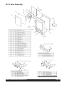
PIC 5 Hopper Bracket Assembly (Part # 62850)
25
23
62850 - Hopper Brkt Asy PIC5
33
26
8
40
7
41
37
39
6
36
1
10
15
4
24
34
9
11
5
38
14
27
35
2
12
20
3
13
31
30
29
28
32
21
22
3
16
17
18
16
19
ITEM NO. PART NO.
DESCRIPTION
ITEM NO. PART NO.
DESCRIPTION
1 62851
Bracket, Hopper PIC5
23 60381
Rivnut, 6-32 ALS4-632-80
2 61461
Button, Restrictor
24 61250
Washer, #8 Split Lock
3 61847
Switch,Toggle-Spst
25 61159-19-5 Seal, Closed Cell Foam 16.5"
4 61226
Funnel, Disconnect
Funnel Whipper
26 61848
Decal, Do Not Pour
27 62825
Plenum, Steam PIC5
6 61255
SHROUD
28 71155-15-b Tubing, Silicone 5/16x1/2
7 62823
Plate, Cover Plenum,
29 71155-16-a Tubing, Silicone 5/16x1/2
8 61116-01-1 Motor, Whipper 120V
30 71155-16-b Tubing, Silicone, 5/16x1/2
9 61334
Washer, Slinger
31 71155-16-c Tubing, Silicone 5/16x1/2
Whipper Base Assy
32 71155-15-a Tubing, Silicone 5/16x1/2
11 60741
O-Ring,2-014
33 61618
Motor,24VDC,Auger,145 RPM
12 07023-04
Screw,6-32x1/4 PH BD M/S SS
34 61458
Blade, Whipper
13 61339
8-32 UNF S.S. ACORN NUT
35 61480
STRAIN RELIEF,HEYCO
14 62395
Chamber, Whipper
36 61353
Screw,8-32 X 1/4" PH PN 18-8 SS
15 61127
O-RING,.335 ID X .079 CS
37 61236
SCRW, 10-32X1/2 PH TR SS
16 61847-1
Nut, Switch, for 61847
38 63068
NUT, 10-32 ESNA SS
17 61242
Label, Flush On/Off
39 61228
Spacer, NYL HEY #334 SPU98
18 61247
Label, Power On Light PIC
40 86877
SCRW, #8X1/2 PH TR HD T/AB ZNC
19 61248
Label, Ready Light PIC
41 62891
Harness, Hopper Brkt PIC5/6
20 61889
Label, PWR ON/OFF PIC
43 61264
Plug, 3/16" Hole
21 63496
Lamp Red w/ Leads
22 63495
Lamp Green w/ Leads
5 61221
10 61523
Crathco® Powdered Beverage Dispensers
Page 43
Page 44
Crathco® Powdered Beverage Dispensers
PIC 5 Final Assembly
6
11
PIC5 - FINAL ASSEMBLY
28
40
1
28
9
25
22
5
14
24
17
7
20
18
13
30
23
3
21
34
10
19
40
35
28
2
16
31
15
16
8
4
39
16
12
ITEM NO. PART NO.
DESCRIPTION
ITEM NO. PART NO.
DESCRIPTION
1 62813
Casing Assy,PIC
22 61237
Fitting,Assy,1/4 fL X 3/4 Hs, Brs
2 62819
Base Assy PIC6
23 61438
Panel,Steam Plenum-Black *IH*
3 63485
Hopper Brkt Asy PIC5
24 61423
Panel, Side Access DV
4 63060
Door Asy PIC5
25 61141
Plate,Back Access
5 62858
Tank Final Assy
26 61305
Screw, 8-32 x 5/8 black
6 62810
Lid Assy PIC6
27 71129
NUT, 8-32 KEPS SS
7 62830
Bracket, Tank Retaining,
28 61303
Screw, #8 x 3/8 black trilobe
8 62832
Splash Panel Plastic PIC
29 61304
Screw,6-32 x 1/2 PPH,SS
9 62974
Control Brkt Assy PIC6
30 60080
Clamp,5/8"Nylon **SC**
10 62831
Splash Panel,
31 62914
Button, Swch PIC5/6 w/ Art
11 62802
Blower Assembly 120V
32 61440
CAP, #8 SCREW SOFT
12 62833
Tray, Drain PIC5
33 61834
Decal, FLVR Strip PIC
13 62836
Tubing Asy,Drain,PIC5
34 100268
Decal,Caution,Behind Drip Tray
14 61372
Hopper Asy PIC Single Pinw
35 62981
Decal, Front Warning PIC
15 62921
Grid Drain PIC5
36 61146
Instr, Manual PIC Domestic
16 71256
Leg, 4" Plastic
37 00800
Label,Serial Number,Name Plate
17 71160
Clip,Syphon Hose w/Blk Adhsv
38 61463
Tag, Instalation
18 62835
Tee, 1.25"
39 62929
Decal, Cup PIC5/6
19 62845-2
TUBING, 1-1/4X14 LONG FLEX
40 62992
Mural Assy Side PIC5-6
20 62845-1
TUBING, 1-1/4X14 LONG FLEX
21 62845-3
TUBING, 1-1/4X14 LONG FLEX
Crathco® Powdered Beverage Dispensers
PIC5 manual -5 rev. C
ECN2075, MJB, 5/25/06
Page 45
PIC 6 Casing Assembly
(Part # 62872)
63493
PIC 6 Base Assembly
(Part # 62876)
Page 46
PIC 6 Lid Assembly
(Part # 62874)
Crathco® Powdered Beverage Dispensers
PIC 5/6 Control Bracket Assembly
(Part # 62848)
62848 - Control Bracket Assy PIC6 ITEM NO.
11
2
6
7
4
4
PART NO. DESCRIPTION
1 62849
Bracket, Control Mtg PIC5 No Display
2 61338
Terminal Board
3 61800
Controller,Pic 3 Portion
4 61131
Relay,12 vdc Coil
5 61481
Transformer,40VA 24/12S
6 61266
STANDOFF, RVRS EDGEMOUNT
7 10073
Label, Ground Symbol
8 60394
Bushing,Snap-7/8"OD x 3/4"
9 61303
10 61272
1
5
Screw, #8 x 3/8 black trilobe
SCRW, #8X3/8 PH PN T/B ZNC/GN
11 62890
Harness, Chassis PIC5/6
12 62928
DECAL, CONTROLLER PIC5/6
12
3
3
3
PIC 6 Door Assembly
(Part # 62875)
7
2
19
1
10
11
15
4
8
9
PIC6 Manual-2
rev. REL
MJB, 1/14/04
ECN1888
Crathco® Powdered Beverage Dispensers
62875 - Door Assembly PIC6
ITEM NO. PART NO. DESCRIPTION
CONFIG DESCR
1
62888
Door Brkt Wldmt,
PIC 6
2
62916
Panel, Rear Door Cvr,
PIC6
3
61479
STRAIN RELIEF,HEYCO
4
62915
Switch, Dispns PIC5/6 No Wafer
5
61303
Screw, #8 x 3/8 black trilobe
6
62910
Merchandiser PIC6 Plastic
7
62889
Harness, Door PIC5/6
8
62919
Graphic PIC6
9
62920
Graphic PIC6
10
62973
Bulb Circle 22W
11
62936
Bracket, Circle Lamp
12
61272
SCRW, #8X3/8 PH PN T/B ZNC/GN
13
61187
Washer, #8 Star Lock
14
70635
TERMINAL, 1/4-032 X 45DEG TAB
15
62856
Decal, 2/3 Full PIC5/6
16
60394
Bushing,Snap-7/8"OD x 3/4"
17
71129
NUT, 8-32 KEPS SS
18
70426
TERM, 1/4F INS QD 18-22 GA
19
62937
Fixture,Circle Fluor w Lamp 22W
20
61327
Decal, Light Replace
Cover
PIC6
Page 47
PIC 6 Hopper Bracket Assembly
(Part # 62863)
26
1
31
30
7
29
35
34
36
6
37
8
9
4
32
5
10
13
25
11
15
3
28
14
2
22
33
20
21
3
19
18
Page 48
ITEM NO.
PART NO.
1
62864
2
3
DESCRIPTION
17
62863, Hopper Brkt Assy PIC6
PIC6 Manual-3.drw
ITEM NO.
PART NO.
Bracket, Hopper PIC6
24
61250
DESCRIPTION
61461
Button, Restrictor
25
62891
Harness, Hopper Brkt PIC5/6
61847
Switch,Toggle-Spst
26
61159-23.5
Seal, Closed Cell Foam 16.5"
4
61226
61848
Decal, Do Not Pour
61221
FTG, FUNNEL DISCONNECT
Funnel Whipper
27
5
28
62865
Plenum, Steam PIC6
6
61255
SHROUD
29
71155-16-PIC6-2
Tubing, Silicone, 5/16x1/2
7
62879
Plate, Cover Plenum,
30
71155-16-PIC6-L
Tubing, Silicone 5/16x1/2
8
61116-01-1
Motor, Whipper 120V
31
61618
MOTOR,24VDC, 145RPM
9
61334
Washer, Slinger
32
61458
Blade, Whipper
10
61523
Whipper Base Assy
33
61480
11
60741
O-Ring,2-014
34
71155-16-PIC6-3
Tubing, Silicone, 5/16x1/2
12
07023-04
Screw,6-32x1/4 PH BD M/S SS
35
71155-16-PIC6-4
Tubing, Silicone, 5/16x1/2
13
61339
8-32 UNF S.S. ACORN NUT
36
71155-16-PIC6-5
Tubing, Silicone, 5/16x1/2
14
62395
Chamber, Whipper
37
71155-16-PIC6-6
15
61127
O-RING,.335 ID X .079 CS
38
86877
16
61847-1
Nut, Switch, for 61847
39
61353
Screw,8-32 X 1/4" PH PN 18-8 SS
17
61242
Label, Flush On/Off
40
61228
Spacer, NYL HEY #334 SPU98
18
61247
Label, Power On Light PIC
41
61236
SCRW, 10-32X1/2 PH TR SS
19
61248
Label, Ready Light PIC
42
63068
NUT, 10-32 ESNA SS
Washer, #8 Split Lock
STRAIN RELIEF,HEYCO
Tubing, Silicone, 5/16x1/2
SCRW, #8X3/8 PH PN T/B ZNC/GN
20
61889
Label, PWR ON/OFF PIC
43
61847-2
21
63496
Lamp Red w/ Leads
44
61452
Nut Round for Switch
Decal, Cleaning Instr 5# HPR
22
63495
Lamp Green w/ Leads
45
61264
PLUG, 3/16 HOLE FAS
23
60381
Rivnut, 6-32 ALS4-632-80
Crathco® Powdered Beverage Dispensers
PIC 6 Final Assembly
62917
62914
62981
62922
Drain Grid PIC6
62992
Crathco® Powdered Beverage Dispensers
Page 49
PIC 1 120V and 120/240V “Q” Model Wiring
Page 50
Crathco® Powdered Beverage Dispensers
PIC 1 230V “E” Model Wiring
Crathco® Powdered Beverage Dispensers
Page 51
PIC1KE or PIC1KAE, 230V “E” Model Wiring
Page 52
Crathco® Powdered Beverage Dispensers
PIC1K or PIC1KA 120 & 120/240 “Q” Model Wiring
Crathco® Powdered Beverage Dispensers
Page 53
PIC1KAEW or PIC1KEW Wiring
Page 54
Crathco® Powdered Beverage Dispensers
CAP1AE or CAP1E 230V “E” Model Wiring
Crathco® Powdered Beverage Dispensers
Page 55
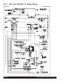
PIC 2/3 120 & 120/240V “Q” Model Wiring
Page 56
Crathco® Powdered Beverage Dispensers
Crathco® Powdered Beverage Dispensers
Page 57
PIC33AE 230V “CE” Model Wiring with 3-Portion Touch Pads
Page 58
Crathco® Powdered Beverage Dispensers
PIC 2/3 100 & 200V “J” Model Wiring
Crathco® Powdered Beverage Dispensers
Page 59
PIC23A, PIC33A 100 & 200V “J” Model Wiring with 3-Portion Touch Pads
Page 60
Crathco® Powdered Beverage Dispensers
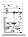
PIC3E or PIC3AE, 230/240VAC 50/60Hz Model Wiring
with Remote Portion Control
Crathco® Powdered Beverage Dispensers
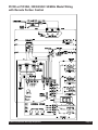
Page 61
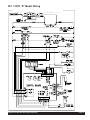
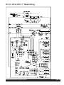
PIC 4 Wiring
Page 62
Crathco® Powdered Beverage Dispensers
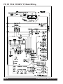
PIC43A 120V & PIC43AQ 120/240V Wiring
Crathco® Powdered Beverage Dispensers
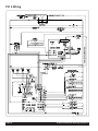
Page 63
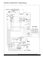
PIC43AZ and PIC43AWZ Model Wiring with 3-Portion Touchpad
Page 64
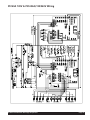
Crathco® Powdered Beverage Dispensers
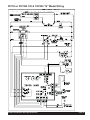
PIC4Z, PIC4AZ, PIC4WZ, PIC4AWZ 240V Model Wiring
Crathco® Powdered Beverage Dispensers
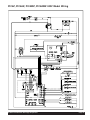
Page 65
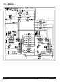
PIC 5/6 Wiring
Page 66
Crathco® Powdered Beverage Dispensers
Crathco® Powdered Beverage Dispensers
Page 67
Grindmaster® Coffee Grinders and Brewers • PrecisionBrew™ Brewing Systems • Espressimo® Espresso Machines
Crathco® Hot Beverage Dispensers • Crathco® Cold and Frozen Beverage Dispensers • AMW Coffee and Tea Systems
Tel (502) 425-4776 • Fax (502) 425-4664 • 1-800-695-4500 (USA & Canada only)
P.O. Box 35020 • Louisville, KY 40232 • USA
www.grindmaster.com • email: [email protected]
© Grindmaster Corporation™, 1996
0807 Form # CC-302-20
PRINTED IN USA
Part # 62780