1
OWNER'S MANUAL
IMPORTANT SAFETY INSTRUCTIONS
CAUTION
RISK OF ELECTRIC SHOCK
DO NOT OPEN
CAUTION: TO REDUCE THE RISK OF
ELECTRIC SHOCK, DO NOT REMOVE
COVER (OR BACK). NO USER-SERVICEABLE
PARTS INSIDE. REFER SERVICING TO
QUALIFIED SERVICE PERSONNEL.
1
2
3
4
5
6
7
8
9
•
Explanation of Graphical Symbols
The lightning flash with arrowhead symbol. within an
equilateral triangle. is intended to alert you to the
presence of uninsulated "dangerous voltage" within
the product's enclosure that may be of sufficient
magnitude to constitute a risk of electric shock to
persons.
The exclamation point within an equilateral triangle
is intended to alert you to the presence of important
operating and maintenance (servicing) instructions in
the literature accompanying the appliance.
Note to CATV system installer:
This reminder is provided to call the CATV system
installer's attention to Article 820-40 of the NEC that
provides guidelines for proper grounding and, in
particular, specifies that the cable ground shall be
connected to the grounding system of the building, as
close to the point of cable entry as practical.
Read these instructions.
Keep these instructions.
Heed all warnings.
Follow all instructions.
Do not use this apparatus near water.
Clean only with dry cloth.
Do not block any ventilation openings. Install in accordance
with the manufacturer's instructions.
Do not install near any heat sources such as radiators. heat
registers. stoves, or other apparatus (including amplifiers)
that produce heat.
Do not defeat the safety purpose of the polarized or
grounding-type plug. A polarized plug has two blades with
one wider than the other. A grounding type plug has two
blades and a third grounding prong. The wide blade or the
third prong are provided for your safety. If the provided plug
does not tit into your outlet, consult an electrician for
replacement of the obsolete outlet.
10
Protect the power cord from being walked on or pinched
particularly at plugs, convenience receptacles, and the point
where they exit from the apparatus.
11
Only use attachments/accessories specified by the
manufacturer.
12
Use only with the cart, stand, tripod. bracket, •
or table specified by the manufacturer, or sold
with the apparatus. When a cart is used, use
• h.
caution when moving the cart/apparatus
combination to avoid injury from tip-over.
~
Unplug this apparatus during lightning storms or when
unused for long periods of time.
13
14
Refer all servicing to qualified service personnel. Servicing
is required when the apparatus has been damaged in any
way, such as power-supply cord or plug is damaged, liquid
has been spilled or objects have fallen into the apparatus, the
apparatus has been exposed to rain or moisture, does not
operate normally, or has been dropped.
FCC INFORMATION (for US customers)
IMPORTANT NOTICE: DO NOT MODIFY THIS UNIT!
This product, when installed as indicated in the instructions
contained in this manual, meets FCC requirements. Modifications
not expressly approved by Yamaha may void your authority,
2
granted by the FCC, to use the product.
IMPORTANT: When connecting this product to accessories
and/or another product use only high quality shielded cables.
Cable/s supplied with this product MUST be used. Follow all
installation instructions. Failure to follow instructions could void
3
your FCC authorization to use this product in the USA.
OTE: This product has been tested and found to comply with
the requirements listed 111 FCC Regulations, Part 15 for Class "B"
digital devices. Compliance with these requirements provides a
reasonable level of assurance that your use of this product in a
residential environment will not result in harmful interference with
other electronic devices.
This equipment generates/uses radio frequencies and, if not
installed and used according to the instructions found in the users
manual, may cause interference harmful to the operation of other
electronic devices.
Compliance with FCC regulations does not guarantee that
interference will not occur in all installations. If this product is
found to be the source of interference, which can be determined by
turning the unit "OFP' and "ON", please try to eliminate the
problem by using one of the following measures:
Relocate either this product or the device that is being affected by
the interference.
Utilize power outlets that are on different branch (circuit breaker or
fuse) circuits or install AC line filter/s.
In the case of radio or TV interference, relocate/reorient the
antenna. If the antenna lead-in is 300 ohm ribbon lead, change the
lead-in to coaxial type cable.
If these corrective measures do not produce satisfactory results,
please contact the local retailer authorized to distribute this type of
product. If you can not locate the appropriate retailer, please
contact Yamaha Electronics Corp., U.S.A. 6660 Orangethorpe
Ave, Buena Park, CA 90620.
The above statements apply ONLY to those products distributed by
Yamaha Corporation of America or its subsidiaries.
Caution-i En
Caution: Read this before operating your unit.
To assure the finest performance, please read this manual
carefully. Keep it in a safe place for future reference.
2 Install this sound system in a well ventilated, cool, dry, clean
place - away from direct sunlight, heat sources, vibration,
dust, moisture, and/or cold. Allow ventilation space of at least
30 cm on the top, 20 cm on the left and right, and 20 cm on
the back of this unit.
3
Locate this unit away from other electrical appliances, motors,
or transformers to avoid humming sounds.
4
Do not expose this unit to sudden temperature changes from
cold to hot, and do not locate this unit in an environment with
high humidity (i.e. a room with a humidifier) to prevent
condensation inside this unit, which may cause an electrical
shock, fire, damage to this unit, and/or personal injury.
5
Avoid installing this unit where foreign objects may fall onto
this unit and/or this unit may be exposed to liquid dripping or
splashing. On the top of this unit, do not place:
- Other components, as they may cause damage and/or
discoloration on the surface of this unit.
- Burning objects (i.e. candles), as they may cause fire,
damage to this unit, and/or personal injury.
- Containers with liquid in them, as they may fall and liquid
may cause electrical shock to the user and/or damage to
this unit.
6 Do not cover this unit with a newspaper, tablecloth, curtain,
etc. in order not to obstruct heat radiation. If the temperature
inside this unit rises, it may cause fire, damage to this unit,
and/or personal injury.
7 Do not plug in this unit to a wall outlet until all connections
are complete.
8 Do not operate this unit upside-down. It may overheat,
possibly causing damage.
9 Do not use force on switches, knobs and/or cords.
10 When disconnecting the power cable from the wall outlet,
grasp the plug; do not pull the cable.
11 Do not clean this unit with chemical solvents; this might
damage the finish. Use a clean, dry cloth.
12 Only voltage specified on this unit must be used. Using this
unit with a higher voltage than specified is dangerous and may
cause fire, damage to this unit, and/or personal injury. Yamaha
will not be held responsible for any damage resulting from use
of this unit with a voltage other than specified.
13 To prevent damage by lightning, keep the power cord and
outdoor antennas disconnected from a wall outlet or the unit
during a lightning storm.
14 Do not attempt to modify or fix this unit. Contact qualified
Yamaha service personnel when any service is needed. The
cabinet should never be opened for any reasons.
15 When not planning to use this unit for long periods of time
(i.e. vacation), disconnect the AC power plug from the wall
outlet.
16 Install this unit near the AC outlet and where the AC power
plug can be reached easily.
Caution-ii En
17 Be sure to read the "Troubleshooting" section on common
operating errors before concluding that this unit is faulty.
18 Before moving this unit, press @MAIN ZONE ON/OFF
to set this unit to the standby mode, and disconnect the AC
power plug from the wall outlet in the main room.
19 VOLTAGE SELECTOR (Asia and General models only)
The VOLTAGE SELECTOR on the rear panel of this unit
must be set for your local main voltage BEFORE plugging
into the AC wall outlet. Voltages are:
.......AC 110/120/220/230-240 V, 50/60 Hz (General model)
.......................... AC 220/230-240 Y, 50160 Hz (Asia model)
20 The batteries shall not be exposed to excessive heat such as
sunshine, fire or like.
21 Excessive sound pressure from earphones and headphones can
cause hearing loss.
22 When replacing the batteries, be sure to use batteries of the
same type. Danger of explosion may happen if batteries are
incorrectly replaced.
WARNING
TO REDUCE THE RISK OF FIRE OR ELECTRIC
SHOCK, DO NOT EXPOSE THIS UNIT TO RAIN
OR MOISTURE.
As long as this unit is connected to the AC wall outlet,
it is not disconnected from the AC power source even
if you turn off this unit by ®MAIN ZONE ONI
OFF. In this state, this unit is designed to consume a
very small quantity of power.
FOR CANADIAN CUSTOMERS
To prevent electric shock, match wide blade of plug to
wide slot and fully insert.
This Class B digital apparatus complies with Canadian
ICES-003.
POUR LES CONSOMMATEURS CANADIENS
Pour eviter les chocs electriques, introduire la lame la
plus large de la fiche dans la borne correspondante de
la prise et pousser jusqu'au fond.
Cet appareil numerique de la c1asse Best conforme a
la norme NMB-003 du Canada.
IMPORTANT
Please record the serial number of this unit in the space
below.
MODEL:
Serial No.:
The serial number is located on the rear of the unit.
Retain this Owner's Manual in a safe place for future
reference.
Contents
i
SIRIUS Satellite Radio™ tuning
(U.S.A. model only)
UCTION
Features
About this manual
Supplied accessories
Part names and functions
Front panel
Rear panel
Front panel display
Remote control
Quick start guide
2
3
3
4
4
5
6
7
8
Installing batteries in the remote control
Using the remote control.
Connl~ctions
Placing speakers
Connecting speakers
Information on jacks and cable plugs
Connecting a video monitor
Connecting other components
Connecting a multi-format player or an external
decoder.
Connecting an external amplifier
Using REMOTE IN/OUT jacks
Connecting a Yamaha iPod universal dock or
Bluetooth™ wireless audio receiver.
Connecting a camcorder or portable audio player
Connecting the FM and AM antennas
Connecting the power cable
Turning this unit on and off
Optimizing the speaker setting for your
lisltming room (VPAO)
Using Auto Setup
When an error message is displayed during
measurement
When a warning message is displayed after
measurement
.......
9
9
9
10
10
II
14
15
16
18
18
19
19
19
20
20
20
21
21
23
23
Basic procedure
Using the SCENE function
Muting audio output temporarily (MUTE)
Adjusting high/low frequency sound
(tone control)
Enjoying pure hi-fi sound (Pure Direct mode)
Using your headphones
Displaying input signal information
Changing information on the front panel display
Enjoy the sound field programs
Selecting sound field programs
Enjoying unprocessed input sources
(Straight decoding mode)
Enjoying sound field programs without surround
speakers (Virtual CINEMA DSP)
Enjoy sound field programs with headphones
(SILENT CINEMATM)
Enjoying more spatial sound fields
(CINEMA DSP 3D mode)
FM/AM tuning
Tuning into the desired PM/AM station
(Frequency tuning mode)
Registering FM/AM stations and tuning in
(Preset tuning mode)
XM® Satellite Radio tuning
(U.S.A. model only)
Connecting XM Mini-Tuner Home Dock
Activating XM Satellite Radio
XM Satellite Radio operations
Registering XM Satellite Radio channels
Displaying the XM Satellite Radio information
Using Bluetooth™ components
Pairing the Bluetooth H1 wireless audio receiver
and your Bluetooth™ componenl..
Playback of the Bluetooth™ component
Other functions
Using the sleep timer
Using the HDMITM control function
24
37
37
37
37
39
.40
41
42
42
44
44
44
45
.45
45
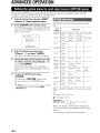
ADVANCED OPERATION
Setting the option menu for each input source
(OPTION menu)
46
OPTlO menu items
46
Outputting a video signal input from another
input source during reproducing a multi-channel
audio signal
48
Editing surround decoders/sound field
programs
Setting sound field parameters
Sound field parameters
49
49
49
Changing various settings of this unit
(SETUP menu)
53
Basic operation of the SETUP menu
Speaker Setup
Sound Setup
Function Setup
DSP Parameter
Memory Guard
54
54
56
57
59
59
Using multi-zone configuration
OPERATION
Playback
Using iPod™
Controlling iPod™
RATION
Preparing remote control
Connecting the SiriusConnect™ tuner
Activating SIRIUS Satellite Radio nt
subscription
SIRIUS Satellite Radio nt operations
Registering the SIRIUS Satellite Radio™
channels
Setting the Parental Lock..
Displaying the SIRIUS Satellite Radio™
information
Connecti ng Zone2
Controlling Zone2
60
60
61
24
24
25
Controlling other components with the remote
control
62
25
25
26
26
26
Advanced setup
27
27
30
30
30
30
31
31
31
33
Setting remote control codes
Resetting all remote control codes
63
63
64
APPENDIX
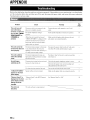
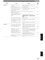
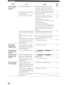
Troubleshooting
General
HDMJTM
Tuner (FM/AM)
XM Satellite Radio (U.S.A. model only)
SIRIUS Satellite Radio™ (U.S.A. model only)
Remote control
iPod™
Bluetooth IM
Auto Setup (YPAO)
Glossary
Sound field program information
Information on HDMITM
Specifications
Index
(at the end of this manual)
List of remote control codes
66
66
69
70
70
71
72
73
74
74
77
79
79
80
81
i
33
33
34
35
36
1 En
I
INTRODUCTION
Features
•
Built-in 7-channel power amplifier
• Minimum RMS Output Power (20 Hz-20 kHz, 0.08%
THO. 8 0)
• FRONT L1R: 95 W + 95 W
• CENTER: 95 W
• SURROUND L1R: 95 W + 95 W
• SURROUND BACK L1R: 95 W + 95 W
•
Speaker/Preout outputs
• Speaker jacks (7-channel + presence 2-channel), preout
output jacks (7 -channel, and subwoofer preoutjack x 2)
•
Input/Output terminals
Input terminals
• HDMI input x 4
• AudiolVideo input
[Audio] Digital input (coaxial) x 2, digital input
(optical) x 2, analog input x 2
[Video] Component video x 2, composite video x 4
• Audio input (analog) x 2
• Multi-channel audio input x I
• Dock input x I
• V-AUX input
I Audio J Analog x I. stereo mini jack x I
I Video] Composite video x I
Output terminals
• Monitor output
IAudiolVideo] HDMI x I
[Vide01 Component video x I, Composite video x I
• AudiolVideo output
[Audio] Analog x I
[Video] Composite video x I
• Audio output
Analog x I
• Zone2 output
Analog x I
• Dolby Pro Logic, Dolby Pro Logic II,
Dolby Pro Logic llx
• DTS NEO:6
• Neural Surround (U.S.A. model only)
• DSD
•
Radio tuners
• FMIAM tuning capability
• XM Satellite Radio tuning capability, using XM MiniTuner and Home Dock, sold separately (U.S.A. model
only)
• SIRIUS Satellite Radio tuning capability, using
SiriusConnect tuner, sold separately (U.S.A. model
only)
•
HDMITM
(High-Definition Multimedia Interface)
• HDMI interface for standard. enhanced or highdefinition video as well as multi-channel digital audio
- Automatic audio and video synchronization (lip sync)
information capability
- Deep Color video signal (30/36 bit) transmission
capability
- "x.v.Color" video signal transmission capability
- High refresh rate and high resolution video signals
capability
- High definition digital audio format signals capability
• Analog video to HDMI digital video up-conversion
(composite video ~ HDML component video ~
HOM!) capability for monitor out
• Analog video input up-scaling for HDMI digital video
output 480i or 480p ~ nop, 1080i or 1080p
• HDMI control capability
•
DOCK jack
• DOCK jack to connect a Yamaha iPod universal dock
(such as YDS-II, sold separately) or Bluetooth wireless
audio receiver (such as YBA-l 0, sold separately)
Other terminals
Remote input x I, Remote output x I
Trigger output x I
•
•
•
•
•
•
Proprietary Yamaha technology for the
creation of sound fields
CINEMA DSP 3D
Compressed Music Enhancer mode
Virtual CINEMA DSP
SILENT CINEMAIM
Digital audio decoders
• Dolby TrueHD, Dolby Digital Plus
• DTS-HD Master Audio. DTS-HD High Resolution
Audio, DTS Express
• Dolby Digital, Dolby Digital EX
• DTS. DTS 96/24, DTS-ES Matrix 6.1,
DTS-ES Discrete 6.1
2 En
•
Automatic speaker setup features
• "YPAO" (Yamaha Parametric Room Acoustic
Optimizer) for automatically optimizing speaker
outputs suitable for listening environments
•
Other features
• I92-kHzI24-bit 01A converter
• OSD (on-screen display) menus that allow you to
optimize this unit to suit your individual audiovisual
system
• Pure Direct mode for pure hi-ti sound for all sources
• Adaptive dynamic range controlling capability
• SCENE function that allows you to change input
sources and sound field programs with one key
• Sleep timer
• Multi-zone function
About this manual
• Some operations can be performed by using either the keys on the front panel or the ones on the remote control. In case the key names differ between
the front panel and the remote control. the key name on the remote control is given in parentheses.
• This manual is printed prior to production. Design and specifications are subject to change in part as a result of improvements. etc. In case of
differences between the manual and product. the product has priority.
• '@MAIN ZONE ON/OFF" or "I]]HDMI 1" (example) indicates the name of the parts on the front panel or the remote control. Refer to the
"Controls diagram" or "Part names and functions" on page 4 for the information about each position of the parts.
• ,'!,!~ indicates a tip for your operation.
• .'" indicates the page describing the related information.
Bluetooth™
[l]DOLBY
TRUE::::E
Bluctooth is a registcrcd trademark of BluelOOlh SIG and is used by
I
Yamaha in accordancc with a license agrecment.
Manufactured under license from Dolby Laboratories.
Dolby. Pro Logic and the double·D symbol are trademarks of Dolby
Laboratories.
"HDMI:' thc "HDMI" logo and "High-Definition Multimedia
~db-HD
Intcrfacc" are tradcmarks. or rcgistercd trademarks of HDMI
Master Audio
Manufactured under license under U.S. Patcnt No's:
5,451,942;5,956.674;5.974,380;5.978,762;6,226,616;6,487 .535 &
othcr U.S. and worldwidc patcnts issued & pending. DTS is a
rcgistcred trademark and thc DTS logos. Symbol, DTS·HD and DTSHD Master A.udio are trademark of DTS. Inc. © 1996-2007 DTS, Inc.
All Rights Rescrvcd.
x.v.Color™
"x.v.Color" is a tradcmark of Sony Corporation.
SILENT '"
CINEMA
"SILENT CINEMA' is a trademark of Yamaha Corporation.
flJ ~u~~S~~.
SIRIUSiJ
Neural Surround'" namc and related logos are trademarks owned
by
Liccnsing LLC.
REA
0
Y
eural Audio Corporation.
XM Mini-1i.Jner
iPod™
SURROUND·SOUND
"iPod" is a tradcmark of Applc Inc.. rcgistcred in thc U.S. and othcr
SIRIUS. XM and all rclatcd marks and logos are tradcmarks of Sirius
countrics.
XM Radio Inc. and its subsidiarics. All rights reserved. Service not
available in Alaska and Hawaii.
Supplied accessories
Check that you received all of the following parts.
• Remote control (see page 9)
• Batteries (AAA, R03, UM-4) x 2 (see page 9)
• Optimizer microphone (see page 21)
• AM loop antenna (see page 20)
• Indoor FM antenna (see page 20)
• Controls diagram
I
3 En
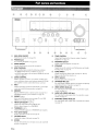
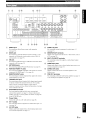
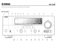
Part names and functions
@
®
©
@
,
CD
®
~
Q)
~
'~
~---~._--{--;-_¥
~$;;;RV.\\1IDIi.\;;;'='='-i!I.-- - - I
;
i
•
1----
®
1
"!
j~;=!~\F========= ===========1==========;====="1\ _..I
@
®
@
®
MAIN ZONE ON/OFF
@
®
Turns this unit on and off (see page 20).
®
PHONES jack
©
ZONE2 ON/OFF
For connecting headphones (see page 26).
Switches Zone2 between on and off (sec page 61).
@
®
®
@
@
®
Front panel display
©
VOLUME control
Displays information on this unit (see page 6).
Controls the volume of this unit (see page 24).
SCENE
Switches between linked sets of input sources and sound lield
programs (see page 24).
4 En
OPTIMIZER MIC jack
For connecting the supplied optimizer microphone and adjusting
output characteristics of speakers (see page 21).
CD
VIDEO (VIDEO AUX) jack
For connecting the video output cable of a camcorder or game
console (see page 19).
(Q)
AUDIO UR (VIDEO AUX) jack
For connecting the audio output cable of a camcorder or game
console (see page 19).
PRESET <ll f>
TUNING/CH <ll f>
Changes FM/AM frequencies or XM/SIRIUS tuner channels.
INPUT selector
Selects an input source (see page 24).
MEMORY
Q)
PURE DIRECT
Changes mode to Pure Direct mode (see page 25). This key
lights up when Pure Direct mode is on.
INFO
FM/AM (CATEGORY <ll f»
Changes the tuner bands between FM and AM.
Select a channel category for a XM/SIRIUS.
STRAIGHT
Toggles between the selected sound tield program and straight
decoding mode (see page 30).
®
CD
C@
®
®
Selects an FM/AM preset station (see page 32) or an XMI
SIRIUS preset channel (see page 35).
PROGRAM selector
Changes sound lield programs (see page 27).
Enables operation of a receiver set in Zone2, including input
source switching, volume control and tuner operation, with the
main amplilier or remote control after this key is pressed.
Registers FMI AM stations as preset stations (see page 32) or
XM/SIRIUS channels as preset channels (see page 35).
®
@
ZONE2 CONTROL
Changes information on the front panel display, such as input
source and sound lield program name (see page 26).
TONE CONTROL
Adjusts high-frequency/low-frequency output of speakersl
headphones (see page 24).
HDMI THROUGH
During standby. lights up under the following conditions:
• the HDMI control function is enabled (see page 57).
• an HDMI signal input to this unit passes through this unit and
output (see page 57).
®
@)
PORTABLE (VIDEO AUX) jack
For connecting the audio output cable of a portable music player
(see page 19).
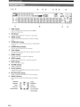
Part names and functions
II!
L.......,=:====r--'
£
@
cD
i
@
SIRIU8 jack
@
For connecting a SiriusConnect tuner (sold separately)
(see page 37).
@
DOCl(jack
For connecting a Yamaha iPod universal dock (YDS-II, sold
separately) or a Bluetooth wireless audio receiver (YBA-I 0,
sold separately) (see page 19).
®
@
@
@
@
ANTENNA jacks
HDMI OUT/HDMI1-4 jacks
REMOTE IN/OUT jacks
For con necting an external component that supports the remote
control function (see page 19).
IJ)
AUDIO OUT jacks
Outputs audio signals from a selected analog input source to an
external component (see page 17).
@
For connecting an HDMI-compatible video monitor or external
components for HDMI inputs 1-4 (see page 16).
®
MULTI CH INPUT terminals
For connecting a player that supports a multi-channel output
(see page 18).
For connecting supplied FM and AM antennas (see page 20).
@
MONITOR OUT terminals
Outputs video signals from this unit to a video monitor, such as
a TV (see page 15).
XMjack
For connecting XM Mini-Tuner in XM Mini-Tuner Home Dock
(separately sold) (see page 33).
AUDIO 1/2 jacks
For connecting external components for audio inputs 1-2
(see page 17).
ZONE2 OUT jacks
Outputs sound of this unit to an external amplitier set in a
different zone.
@
PRE OUT terminals
For connecting a subwoofer with built-in amplitier (see page II)
or an external power amplifier (see page 18).
TRIGGER OUT jack
For connecting an external terminal with a trigger input terminal
to operate it linked with operation of this unit. For example,
when an electric screen that supports a trigger input is
connec1ted, it opens and closes linked with operation of an input
source selected in this unit.
®
SPEAKERS terminals
For connecting front right and left, center, surround and
surround back speakers (see page II). Connect the presence
speakers (see page 12) or the speakers for Zone2 (see page 60)
to the EXTRA SP jacks.
®
Power Cable
Connect this cable to an AC wall outlet (see page 20).
(j])
AV 1-I)jacks
For connecting external components for audio/video inputs 1-6
(seepage 16).
(j])
I
AV OUT jacks
Outputs audio/video signals from a selected analog input source
to an eJaernal component (see page 17).
5 En
Part names and functions
@
CD® ®
o
o
j 00
000
00000
o
00000
000
088
i
o
@
CD
HOMI indicator
Lights up during normal communication when HDMI is
selected as an input source.
@
XM indicator
@
SIRIUS indicator
Lights up when an XM tuner is selected as an input source.
Lights up when a SiriusConnect tuner is selected as an input
source.
@
CINEMA OSP indicator
Lights up when a sound field program that uses CI EMA DSP
is selected.
@
CINEMA OSP 3D indicator
®
Tuner indicator
Lights up when CINEMA DSP 3D is activated.
Lights up during receiving radio broadcast signals from an FM/
AM station (see page 31).
(J)
ZONE2 indicator
®
SLEEP indicator
Lights up when Zone2 is turned on (see page 60).
Lights up when the sleep timer is activated (see page 45).
®
MUTE indicator
@
VOLUME indicator
®
Cursor indicators
Flashes when audio is muted.
Displays volume levels.
Light up when corresponding cursors on the remote conlroJ are
available for operations.
@
Multi information display
@
Speaker indicators
Displays menu items and settings for the current operation.
Indicate speaker terminals from which signals are currently
output.
Subwoofer ->-'~"l SW
Presence L~{ID
Front L
Surround L
Surround back L
6 En
I ~ -- Center
II PR +- Presence R
,-~ ~"'I R
-Cill
·-~SBLI
+-
I SR r
Front R
Surround R
[]I] ISBR~._· Surround back R
!\\.~ ••..•.~-- Surround back
(J) ®
I
®
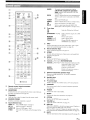
Part names and functions
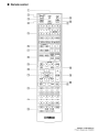
[A]/[B]
DOCK
TUNER
SIRIUS
XM
MULTI
To control external components using the
IWExternal component operation
keys separately from operations of this unit
(see page 62).
Selects a Yamaha iPod universal dock/Bluetooth
wireless audio receiver connected to the DOCK
jack.
Selects the FM/AM tuner.
Selects a SiriusConnect tuner as an input source.
Selects an XM tuner as an input source.
Selects a signal input from the MULTI CH
INPUT jack on the rear panel as an input source.
Tuner keys
FM
AM
(CATEGORY <J /
MEMORY
PRESET 1:::./
TUN.lCH I:::. /
Select the FM band or AM band.
[»
'V
'V
Select a channel category for a XMI
SIRIUS.
Presets radio stations.
Select a preset station.
Change FM/AM frequencies or
XM/SIRIUS tuner channels.
INFO
Changes information on the front panel display, such as input
source and sound field program name (see page 26).
Sound selection keys
Selects sound field programs (see page 27).
SCENE
Switches between linked sets of input sources and sound tield
programs (see page 24).
SETUP
Displays the SETUP menu (see page 54).
Cursors I:::. /
Cursors I:::. /
'V 1 <J / [>/ENTER/RETURN
'V 1 <J / [> Select menu items displayed on the
ENTER
RETURN
front panel display or on a video
monitor. or change settings.
Confirms a selected item.
Returns to the previous screen or
ends the menu display.
External component operation keys
Operate recording, playback etc. of external components
(see page 62).
Numeric keys
Enter numbers.
TV control keys
Enables operations of a monitor such as a TV and a projector.
CODE SET
ITJ
Sets remote control codes for external component operations
(see page 63).
Remote control signal transmitter
Transmits infrared signals.
~
MAINr.~ONE2
Switches the zone to be operated by the remote control between
the Main zone and Zone2 (see page 61).
rnJ
ITIJ
SLEEP
Switches the sleep timer operations (see page 45).
!lID
Input selection keys
HDMI 1-4
Selects HDMI inputs I through 4.
AV 1-6
Selects AV inputs I through 6.
AUDIO 1/2 Selects AUDIO inputs I and 2.
V-AU X
Selects the V-AUX jack on the front panel of this
unit.
OPTION
Displays the OPTION menu (see page 46).
SOURCE POWER
Switches an external component on and off.
~
POWER
Switches this unit on and standby.
TRANSMIT
Lights up when a signal is output from the remote control.
~
~
[j]]
VOLUME +1Adjust the volume of this unit (see page 24).
~
DISPLAY
When XM or SIRIUS is selected as an input source: Displays or
does not display the OSD on the video monitor.
When an iPod is connected: Changes the operation mode of the
iPod connected to the Yamaha iPod universal dock (see page 42).
1m
MUTE
Turns the mute function of the sound output on and otT (see page 25).
7
En
I
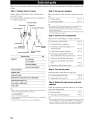
Quick start guide
When you use this product for the first time, perform the steps below. See the related pages for details of operations and
settings.
Step 1: Prepare items for setup
Step 2: Set up your speakers
Prepare speakers, DVD player, cables, and other items
necessary for setup.
For example, prepare the following items for setting up a
7. I-channel sound system.
Front right speaker
Place your speakers in the room and connect them to this
unit.
• Placing speakers
I&P.IO
• Connecting speakers
I&P. II
,0,
~<il~
Video monitor
Surround right speaker
Front left speaker
\
Step 3: Connect your components
S"~~k
!
right
speaker
Components
(such as DVD player)
Surround left speaker
Surround back left
speaker
Requirements
Speakers
• This unit has a YPAO (Yamaha Parametric Room Acoustic Optimizer)
that automatically optimizes this unit based on room acoustic
characteristics (audio characteristics of the speakers, speaker positions,
and room acoustics, etc.).
You can enjoy good balanced sound without special knowledge by using
the YPAO technology (see page 21).
Front speaker
qty.
2
Center speaker
Surround speaker
2
Surround back speaker
2
• Connecting a video monitor
• Connecting other components
• Connecting a multi-format player or an
external decoder
I&P.18
• Connecting an external amplifier
I&p' 18
• Connecting a Yamaha iPod universal
dock or Bluetooth wireless audio receiver
I&P. 19
• Connecting the FM and AM antennas
I&P. 20
• Connecting an XM Mini-Tuner Home
Dock
I&p' 33
• Connecting a SiriusConnect tuner
I&P. 37
Step 4: Turn on the power
Active subwoofer
Speaker cable
Connect your TV, DVD player, or other components.
5
Connect the power cable and turn on this unit.
Subwoofer cable
• Connecting the power cable
Ir$'P.
Reproduction component such as OVO player
• Turning this unit on and off
I&p' 20
20
Video monitor such as TV
Video cable or HOMI cable
2
Audio cable
2
,0,
~<il~
• Prepare at least two (front) speakers. Speakers other than front speakers
may be used in the following order of preference:
I Two surround speakers
2 One center speaker
:> One or two surround back speakers
• If your video monitor is a CRT, we recommend that you use magnetically
shielded speakers.
• An audio cable is not required when you use an HDMI cable.
8 En
Step 5: Select the input source and start
playback
Select the component connected in the step 3 as an input
source and start playback.
• Basic procedure
I&P,24
• Selecting sound field programs
I&P. 27
,I,
~<il~
• This unit supports the SCENE function that changes the input source and
sound field program at one time. Four SCENES are preset for different
purposes for Blu-ray disc, DVD and CD. You can select a SCENE from
those just by pressing a remote control key. See page 24 for details.
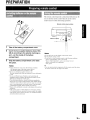
PREPARATION
Preparing remote control
The remote control transmits a directional infrared ray. Be
sure to aim the remote control directly at the remote
control sensor on this unit during operation.
Remote control sensor window
within 6 m (20 tt)
1
Take l>ff the battery compartment cover.
2
Insert the two supplied batteries (AAA, R03,
UM-4)1 according to the polarity markings (+
and -) on the inside of the battery
compartment.
3
Snap the battery compartment cover back
into place.
Notes
• Change all batteries if you notice the following conditions:
- the operation range of the remote control narrows.
- the transmit indicator does not flash or is dim.
• Do nO!: use old batteries together with new ones.
This may shorten the Iife of the new batteries or cause old batteries
to leak.
• Do not use different types of batteries (sueh as alkaline and
manganese batteries) together. Specification of batteries may be
different even though r.hey look the same.
• If you find leaking batteries, discard the batteries immediately,
taking care not to touch the leaked material. If the leaked material
comes into contact with your skin or gets into your eyes or mouth,
rinse il: away immediately and consult a doctor. Clean the battery
compartment thoroughly before installing new batteries.
• Dispose of the old batteries cOlTectly in accordance with your local
regulations.
• If the remote control i:; without batteries for more than 2 minutes,
or if exhausted batteries remain in the remote control, the contents
of the memory may be cleared. In such a case, install new batteries
and set the remote control code.
Notes
• Do not spill water or other liquids on the remote control.
• Do not drop the remote control.
• Do not leave or store the remote control in the following conditions:
- places of high humidity, such as near a bath
- places of high temperatures, such as near a heater or stove
- places of extremely low temperatures
- dusty places
'"
~<il~
• You can operate external components with this remote control by setting
the remote control code. See page 62 for details.
I
9En
Connections
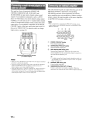
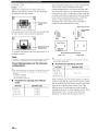
This unit supports up to 7. I-channel surround playback. We recommend the following speaker layout in order to obtain
the optimum surround effect.
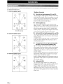
7.1-channel speaker layout
Speaker channels
•
Front left and right speakers (Fl and FR)
The front speakers output the front channel sounds (stereo
sound) and effect sounds. Place these speakers at an equal
distance from the ideal listening position. When using a
screen, the appropriate top positions of the speakers are
about 1/4 of the screen from the bottom.
,'SL
SR'I
SL
SR
30 em (12 in) or more
FR
,
'
'SWI
, ,
SL
SR
5.1-channel speaker layout
FL
,
'
'SWI
,
,
'-'
" SL
SL
10
En
FR
Surround left and right speakers (Sl and SR)
The surround speakers output effect sounds and surround
sounds. Place them at the rear left and rear right facing the
listening position.
To obtain a natural sound flow in the S.I-channel speaker
layout, place them slightly further back than in the 7.1channel speaker layout.
•
" SL
Center speaker (C)
The center speaker outputs the center channel sounds
(dialog, vocals, etc.). Place it halfway between the left and
right speakers. When using a TV, place the speaker just
above or just under the center of the TV with the front
surfaces of the TV and the speaker aligned. When using a
screen, place it just under the center of the screen.
•
6.1-channel speaker layout
FL
•
Surround back left and right speakers (SBl
and SBR) I Surround back speaker (SB)
The surround back left and right speakers output rear
effect sounds. Place them at the rear of the room facing the
listening position at least 30 cm away from each other,
ideally at the same distance as that between the front left
and right speakers.
In the 6. I-channel speaker layout, surround back left and
right channel sound signals are mixed down and output
from the single surround back speaker.
In the S.I-channel speaker layout, surround back left and
right channel sound signals are output from the surround
left and right speakers.
•
Subwoofer (SW)
The subwoofer speaker outputs bass sounds and lowfrequency effect (LFE) sounds included in Dolby Digital
and DTS signals. Use a subwoofer with a built-in
amplifier, such as the Yamaha Active Servo Processing
Subwoofer System. Place it exterior to the front left and
right speakers facing slightly inward to reduce reflections
from a wall.
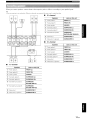
Connections
When you connect speakers, connect them to the respective jacks as follows, according to your speaker layout.
'"
~"'~
• You can connect up to two snbwoofers. When two subwoofers are connected, the same sound is output from them.
•
@ CD
[®
() 8
(J)
6.1-channel
@
Speakers
CD
8 88 8
Front speaker L
FRONT (L)
@ Front speaker R
FRONT (R)
@ Center speaker
CENTER
@
Surround speaker L
SURROUND (L)
@ Surround speaker R
SURROUND (R)
@ Surround back speaker
SURROUND
BACK/BI-AMP (SINGLE)
®
®
Subwoofer I
SUBWOOFER 1
Subwoofer 2 (optional)
SUBWOOFER 2
•
5.1-channel
Speakers
st..:
,""'' ' ' "' I ~
~
1 - - - - - - - - 1 - - - -.......
-·---
t
OOi.. ~
.0.
•
!
Jacks on this unit
CD
Jacks on this unit
Front speaker L
FRONT (L)
@ Front speaker R
FRONT (R)
@ Center speaker
CENTER
@ Surround speaker L
SURROUND (L)
@ Surround speaker R
SURROUND (R)
®
®
Subwoofer I
SUBWOOFER 1
Subwoofer 2 (optional)
SUBWOOFER 2
7.1-channel
Speakers
CD
Jacks on this unit
Front speaker L
FRONT (L)
@ Front speaker R
FRONT (R)
@ Center speaker
CENTER
@
Surround speaker L
SURROUND (L)
@
Surround speaker R
SURROUND (R)
@ Surround back speaker L
SURROUND
BACK/BI-AMP (L)
!J) Surround back speaker R
SURROUND
BACK/BI-AMP (R)
®
®
Subwoofer I
SUBWOOFER 1
Subwoofer 2 (optional)
SUBWOOFER 2
I
11
En
Connections
Presence speakers
You can connect presence speakers (PLIPR) that output
front effect sounds to this unit. With CINEMA DSP sound
field programs (see page 27) and their CINEMA DSP 3D
functions, a sound with a richer and more spacial presence
can be created. You can adjust the vertical position of
center sound such as a dialog (see page 54).
0.5 to 1 m (1 to 3 tt)
0.5 to 1 m (1 to 3 tt)
II
Ul
PRO
FL
1.8 m
1.8 m
(6 tt)
(6 tt)
•
To use the presence speakers, connect them to the EXTRA
SP jacks and set "Extra SP Assign" in "Speaker Setup" in
the SETUP menu to "Presence" (see page 54).
Presence
speaker R
Presence
speaker L
,I,
~<i>~
• Although you can connect both surround back speakers and presence
speakers 10 this unil. you cannOI output sounds from those speakers at the
same time. This unit automatically selecls speakers to output sounds
according to the selected input source and sound field program .
• You can connect Zone2 speakers with a multi-zone function to the
EXTRA SP jacks. For details, see page 60.
12 En
Connections
Connec1ting the speaker cable
Caution
• A speaker cable is a pair of insulated cables running side by side in general. One of the cables is colored differently
or striped to indicate a polarity. Connect one end of the colored/striped cable to the "+" (red) terminal of this unit
and the other end to that of your speaker, and connect one end of the other cable to the "-" (black) terminal of this
unit ancl the other encl to that of your speaker.
• Before connecting the speakers, be sure to disconnect the power cable.
• Do not let the bare speaker wires touch each other or any metal part of this unit. This could damage this unit ancl/or
speakers. If the circuit shorts out, "CHECK SP WIRES!" appears on the front panel display when this unit is turned
on.
• If your video monitor is a CRT, use magnetically shielded speakers. If images on the monitor are still distorted even
when you use the magnetically shielded speakers, place the speakers away from the monitor.
• Use speakers with an impedance of 6-ohm or larger. Set speaker impedance in "ADVANCED SETUP" before
connecting the speakers. You can also use 4-ohm speakers as the front speakers when you set "SP IMP" to
"6QMIN" (see page 64).
1
Remolve approximately 10 mm (0.4 in) of
insulcltion from the end of each speaker
cable and then twist bare wires of the cable
together so that they will not cause a short
circuits.
10 mm (0410)
I~
Using bi-amplification connections
You can connect speakers that support bi-amplification
connections to this unit. To connect the speakers via a biamp connection, connect them to the FRONT jacks and
SURROUND BACKlBI-AMP jacks as illustrated.
To enable the bi-amp connection, connect the power cable
to the wall outlet, display the ADVANCED SETUP menu
and set "BI AMP" to "ON" (see page 64).
Front speakers
Right
2
Left
the knob, insert the twisted bare
wires into the hole, and then tighten the
knob.
LOOSfm
This unit
,0,
0<i>~
• You can connect the presence speakers (see page 12) or the speakers in
the second zone (Zone2) (see page 60) to the EXTRA SP jacks.
Connecting the banana plug (Except U.K.,
Europe, Russian, Asia and Korea models)
Tighten the knob, and then insert the banana plug into
the end of the terminal.
Caution
Before making bi-amplification connections, remove
any brackets or cables that connect a woofer with a
tweeter. Refer to the instruction manuals of speakers for
details.
When not making bi-amplification connections, make
sure that the brackets or cables are connected before
connecting the speaker cables.
Note
• You cannot use surround back speakers or extra speakers (presence and
Zone2 speakers) when bi-amplification connections are made.
I
13 En
Connections
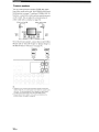
This unit has the following input and output jacks. Use jacks and cables appropriate for components that you are
connecting.
•
Audio jacks
•
Jack and cables
AUDIO jacks
Description
To transmit conventional analog
(stereo) signals. Use stereo pin
(white)
Video/audio jacks
cables. Connect red plugs to red
jacks (R) and white plugs to white
jacks (L).
Jack and cables
HDMI jacks
Description
To transmit digital video and
LHDMI)'-~
digital audio signals. Use HOMI
cables.
,',
~<i>~
AUDIO
(red)
COAXIAL jacks
To transmit coaxial digital audio
signals. Use pin cables for digital
(orange)
e.-~
audio signals.
COAXIAL
OPTICAL jacks
To transmit optical digital audio
signals. Use opticalliber cables for
~,-{@Jmm-
optical digital audio signals.
OPTICAL
•
• We recommend that you use a commercially available 19-pin HOMI
cable no longer than 5 meters (16 feet) with the HOMI logo prinled on it.
• If you connect this unit to a componenl that has a OVljack, an HOMII
OVI-O cable is required.
• You can check error information on HDM! connections (see page 79).
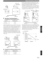
Video jacks
Jack and cables
Description
A video signal input to this unit is output from the jacks
in MONITOR OUT for the same kind of signal as the
input signal.
For example, if a VCR with a composite output signal
and a OVO player with a component video output
signal are connected, connect both VIDEO jack and
COMPONENT VIDEO jack in MONITOR OUT to the
video monitor.
If an HOMI input compatible monitor is connected, this
unit automatically converts an analog signal that is
input from a video input jack to a digital video signal,
and then outputs it from the HDMI OUT jack.
Input
VIDEO jacks
To transmit conventional
composite video signals. Use video
VIDEO
e.-~
pin cables.
(yellow)
_
GGG
HOMI
chrominance red (PR) components.
PR~ +-
Use component video cables.
(red)
+-
(blue)
y~+(green)
14 En
signals that include luminance (Y),
) -------~~ ""'" C
---~
.. ........
P.
....,~
Paltl--+-
--------.p.
Not converted
J
"'"""""-
Y
chrominance blue (PB) and
COMPONENT
VIDEO
P.~
To transmit component video
l
....,
PA
COMPONENT VIDEO
jacks
Output
Converted
Connections
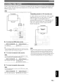
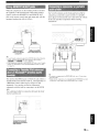
Connect a video monitor such as a TV or projector to an output jack of this unit. You can select one of the following three
types according to the input signal format supported by the video monitor: HDM! OUT, COMPONENT VIDEO and
VIDEO (composite video).
Note
• Make sure that this unit and video monitor are unplugged from the AC wall outlets.
Outputting sound of a TV from this unit
TV or projector
To output sound of a TV from this unit, connect an audio
output terminal of the TV to any of the AV 1-6 jacks.
If the TV supports an optical digital output, we
recommend that you use the AV 1. Connecting to the AV I
allows you to switch an input source to the AV input I
with a just a single key operation using the SCENE
function (see page 24).
TV or projector
Digital output
(optical)
•
To connect an HOMI video monitor
Jacks em components
Q) HOMI input
Jacks on this unit
HOMIOUT
.::\¥~
• This unit supports the HOMI control function. By connecting a TV that
supports the HOMI control, operations of this unit can be controlled with
the remote control of the TV. For details. see page 45.
•
To connect component video monitor
Note
Note
• If the video monitor connected to this unit supports the HOM! control
function, we recommend that you connect its audio output jack to the
OPTICAL jack of the AV I jacks of this unit. By doing so. this unit
automatically turns on and "TV" of SCENE is automatically selected
when you turn on the video monitor. You can obtain the same result even
if you connect the audio output jacks to the AV2-6. AUDIO 1-2 or VAUX jacks by assigning those jacks to TV in advance (see page 24).
• Only video signals input from this unit via the COMPONENT VIDEO
jack arc output from the COM PONE T VIDEO jack.
Jacks em components
®
Component video output
Jacks on this unit
MONITOR OUT
(COMPONENT VIDEO)
•
To connect composite video monitor
Note
• Only video signals input from this unit via the VIDEO jacks are output
from the VI. EO jacks.
Jacks (In components
@ Video input (composite)
Jacks on this unit
I
MONITOR OUT (VIDEO)
15 En
Connections
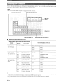
This unit has input and output jacks for respective input and output sources. You can reproduce sound and movies from
input sources selected with the front panel display or remote control.
Note
• Make sure that this unit and other components are unplugged from the AC wall outlets.
Audio/video input (AV 1-6)
Audio/video output (AV OUT)
HDMI input
(HDMI1-4)
pGG
p,G G~=Y=~~=J'"~·)i·
vGGGGGGG
Q G G G G G G Gli Glr=+I==::;=::j:::::~=;:::::~~:::::::;,
~O'~~G~GG"91~!
AVI
AV2
AV3
AV",
AVS
AV6--OUT- .... AUDlOI
AlIOlO2---MUlTICHINPUT
Audio input (AUDIO 1-2)
•
Audio output
(AUDIO OUT)
OUT
Multi channel audio input (MULTI CHI
Audio and video player/Set-top box
Output jacks on the connected external component
External
components
External component
Input sources/jacks of this unit
Signals
AudiolYideo
Output jacks
HDMloutput
with HDMI output
External component
with component video
Audio
Optical digital output
Video
Component video output
Audio
Coaxial digital output
Video
Component video output
Audio
Coaxial digital output
Video
Composite video output
Audio
Optical digital output
Video
Composite video output
Audio
Analog audio output
Video
Composite video output
Audio
Analog audio output
Video
Composite video output
HDMI I (BDIDVD)
HDMI I
HDMI2
HDMI2
HDMI3
HDMI3
HDMI4
HDMI4
AVI (TV)
OPTICAL
COMPONENT VIDEO
output
External component
with composite video
AV2
COAXIAL
COMPONENT VIDEO
AV3 (CD)
COAXIAL
VIDEO
output
AV4
OPTICAL
VIDEO
AV5
AUDIO
VIDEO
AV6
AUDIO
VIDEO
:\(,{~
• Input sources in parentheses are recommended to connect to the respective jacks. If a component is compatible with the SCENE function, you can switch
the input source to that component with a single key operation using the SCENE function (see page 24).
• You can change the name of the input source displayed on the front panel display or the video monitor as necessary (see page 59).
• See page 60 on how to use ZONE2 OUT jack.
16 En
Connections
•
Audio player
Output jacks on the connected external component
Input sources/jacks of this unit
Ex.ternal components
External component with optical digital
Output jacks
Optical digital output
output
External component with coaxial digital
Coaxial digital output
output
External component with analog audio
output
Analog audio output
AV I (TV)
OPTICAL
AV4
OPTICAL
AV 2
COAXIAL
AV 3 (CD)
COAXIAL
AV 5
AUDIO
AV6
AUDIO
AUDIO I
AUDIO
AUDIO 2
AUDIO
~\~'~
• We recommend connecting the coaxial digital output terminal of a CD player to the AV3 jack.
About audio/video output jacks
Among the analog audio and analog video signals input to this unit via input terminals, the audio/video signals of the
selected input sources are output from the AV OUT jack and AUDIO OUT jack. An HDMI input signal,
COMPONENT VIDEO input signal or digital audio input signal cannot be output. When using the AV OUT jacks or
AUDIO OUT jacks, connect them as follows:
When usiing the AV OUT jacks:
connect them to composite video and analog audio input jacks of an external
component.
When using the AUDIO OUT jacks: connect them to analog audio jacks of an external component.
I
17 En
Connections
This unit has 8 sets of input jacks (FRONT L/R,
CENTER, SURROUND L/R, SUR. BACK and
SUBWOOFER) to input multi-channel analog sound
signals. If your playback component, such as a DVD
player or SACD player, has multi-channel analog output
capability, you can enjoy up to 7.I-channel multi-channel
sound. To output multi-channel sound, connect the audio
output jacks of your playback component to the MULTI
CH INPUT jacks of this unit, and set the input source of
this unit to "MULTI CH." For details on how to change
input sources, see page 24.
l
R
l
COUl
Ol c:
n ...
"'0
o c:
c:
:::>
-Q.
R
Ul
c:
co
~
0
~
0
The same channel signals are output from the jacks of the
PRE OUT terminals as from their corresponding
SPEAKERS terminals. When connecting an external
power amplifier (pre-main amplifier) to enhance speaker
output, connect the input terminals of the power amplifier
to the PRE OUT terminals of this unit.
Note
• When a component is connected to the PRE OUT terminals, do not
connect speakers to the SPEAKERS terminals corresponding to those
PRE OUT terminals.
<D
FRONT (PRE OUT) jacks
®
SURROUND (PRE OUT) jacks
Front channel output jacks.
(")
C1)
:::>
~
Surround channel output jacks.
0
~
@
Multi-format player/External decoder
(7.1-channeloutput)
,"
~Ii>~
• To output surround back channel signals through these jacks. set
"Sur.B LlR SP" to any parameter except for "None" in "Speaker
Setup" (see page 55).
Notes
• When you select "MULTI CH" as the input source. the digital sound field
processor is automatically disabled.
• Since this unit does not redirect signals input at the MULTI CH INPUT
jacks to accommodate for missing speakers. connect at least a 5.1channel speaker system when using this feature.
• When the input source is switched to "MULTI CH." images input from a
component connected to "AY 1-6" or "Y-AUX" can be displayed on a
video monitor (see page 48). If your DYD player does not support multichannel digital output, connect it to these input jacks.
18
En
SUR. BACK (PRE OUT) jacks
Surround back output jacks. When you only connect one
external amplifier for the surround back channel. connect it to
the SUR. BACK (SINGLE) jack.
~
@
CENTER (PRE OUT) jack
Center channel output jack.
®
SUBWOOFER (PRE OUT) 1/2 jack
Connect a subwoofer with a built-in amplitier. When two
subwoofers are connected, the same sound is output from them.
Connections
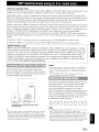
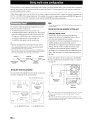
When the components are the Yamaha products and have
the capability of the transmission of the remote control
signals, connect the REMOTE IN and REMOTE OUT
jacks to the remote control input and output jack with the
monaural analog mini cable as follows.
Remote
control out
Remote
control in
Infrared signal
receiver or Yamaha
component
Yamaha component
(CD or DVD player, etc.)
The V-AUX terminals on the front panel are useful for
connecting a camcorder, a game console or a portable
music player to this unit. Be sure to turn down the volume
of this unit and other components before making
connections.
f-r\~:~~~? !,1
,
,
•
,--,
Ol>:
::
I
<:
ii:
~
o
.:-\~'-:.
-gs-
L
I
0>
1::::>
- I l_l
"0
I: 0
-u:l
-<0
I:
III
III
s.
ci"
.g
• If your Yamaha component supports the SCENE link playback function,
remote connection automatically starts playback when you press
(0SCENE (or [IDSCENE) to select a SCENE.
• If the component connected to the REMOTE OUT jack is not a Yamaha
product. set "SCENE fR" in the ADVANCED SETUP menu to "OFF"
(see page 64).
V
I::::l
I
a-
Game console/Camcorder
I:
a.
o'
Music player
'"
~<i>~
This unit has the DOCK jack, to which you can connect a
Yamaha iPod universal dock (YDS-II, sold separately) or
a Bluetooth wireless audio receiver (YBA-H), sold
separately). You can play an iPod or a Bluetooth
component with this unit by connecting it to the DOCK
jack.
Use a dedicated cable for connection between the dock!
receiver and this unit.
• To connect a component to the PORTABLE jack. use a 3.5 mm stereo
mini plug cable.
• When external components are connected both the PORTABLE jack and
AUDIO jack, sound input from the PORTABLE jack is output.
I
Yamaha iPod universal
docklBluetooth wireless
audio receiver
19 En
Connections
~onneCtingthe power-cable
An indoor FM antenna and an AM loop antenna are
supplied with this unit. Connect these antennas properly to
the respective jacks.
After all connections are complete, plug the AC power
cable of this unit into an AC wall outlet.
To the AC wall outlet
AM loop
antenna
Indoor FM antenna
.
Power cable
Ground (GND terminal)
The GND terminal is not for earth grounding.
To reduce noises, connect a ground bar or a
vinyl-covered wire with a copper plate at its tip,
and place it in the moist ground.
'"
~<il~
• The supplied antennas are normally sensitive enough to obtain good
reception.
• Position the AM loop antenna away from this unit.
• If you cannot get good reception. we recommend that you use an outdoor
antenna. For more details, consult the nearest authorized Yamaha dealer
or service center.
• Always use the AM loop antenna even when the outdoor antenna is
connected.
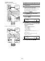
Assembling the AM loop antenna
1
Press@MAIN ZONE ON/OFF (or
IlIDPOWER) to turn on this unit.
2
Press @MAIN ZONE ON/OFF (or
[j])POWER) again to turn off this unit
(standby).
:(j{::.
• The unit needs a few seconds until ready 10 play back.
• You can also turn on this unit by pressing@SCENE (or [illSCENE).
• This unit consumes a small amount of electricity even during standby.
We recommend disconnecting the power cable from the AC wall outlet.
Caution
Do not unplug this unit while it is turned on. Doing so
may damage this unit or cause the settings of this unit
to be saved incorrectly.
Connecting the AM loop antenna
The wires of the AM loop antenna have no polarity. You
can connect either wire to the AM terminal and the other
to the GND terminal.
Press and hold
20 En
Insert
Release
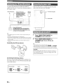
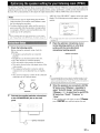
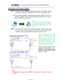
imizing the speaker setting for your listening room (YPAO)
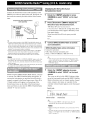
This unit has a Yamaha Parametric Room Acoustic Optimizer (YPAO). With the YPAO, this unit automatically adjusts the
output characteristics of your speakers based on speaker position, speaker performance, and the acoustic characteristics of
the room. We recommend that you first adjust the output characteristics with the YPAO when you use this unit.
Notes
• Loud test tones may be output during the automatic
setup procedure. Do not allow small children to enter
the room during the procedure.
• To achieve the best results, make sure the room is as
quiet as possible while the automatic setup procedure
is in progress. If there is too much ambient noise, the
results may not be satisfactory.
"MIC ON. View OSD MENU" appears on the front panel
display. The following menu screen appears on the video
monitor.
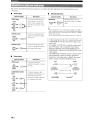
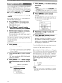
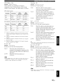
1 Auto Setup
E~<t.ra
>2 one 2
"*
.. t~atut"al
[EtHEF:]: Stat'!..
'"
0<il~
• You can bring up the above menu screen from the SETUP menu
(see page 54).
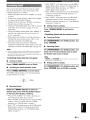
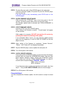
3
Check the following points.
Before starting the automatic setup, check the
following.
• All speakers and subwoofer are connected
properly.
• Headphones are disconnected from this unit.
• The video monitor is connected properly.
• This unit and the video monitor are turned on.
• This unit is selected as the video input source of the
video monitor.
• The connected subwoofer is turned on and the
volume level is set to about half way (or slightly
les:;).
• The crossover frequency controls of the connected
subwoofer are set to the maximum.
CROSSOVER/
HIGH CUT
VOlUM~
0-0
MIN
MAX
MIN
MAX/
'\
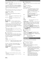
Connect the supplied optimizer microphone
to the OPTIMIZER MIC jack on the front
panE!!.
Place the optimizer microphone at your
normal listening position on a flat level
surface with the omni-directional
microphone heading upward.
Optimizer microphone
,',
O<il~
• It is recommended that you use a tripod or something similar to tix the
optimizer microphone at the same height as your ears would be when
seated in your listening position. You can fix the optimizer microphone to
the tripod with the attaching screw of the tripod.
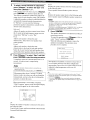
4
Subwoofer
2
EO T'~pe"
Star·f...
Pt-'esenee
[ .. ] ..... [ .... ]: UP/[)Ohll',
,',
0<il~
• You can I anually adjust the output characteristics of your speakers
with "2 Manual Setup" in the SETUP menu. For details, see page 54.
1
SP H=.=.i 9n
t·~one
When the speakers are connected to EXTRA
SP jacks, press IITICursor 6. repeatedly to
select "Extra SP Assign," and then press
IITICursor <l I r> to select how to use EXTRA
SP jacks from "Zone2," "Presence" or
"None."
If this unit does not work when you press IITICursor,
press IIQISETUP once and then operate this unit.
.__ .J
I
6~r--- Optimizer microphone
21
En
Optimizing the speaker setting for your listening room (YPAOj
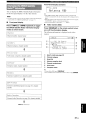
5
To select a sound character for adjustment,
press [j]Cursor Vto select "EO Type" and
then press [j]Cursor <l 1 C>.
If this unit does not work when you press [j]Cursor,
press ImISETUP once and then operate this unit.
This unit has a parametric equalizer that adjusts the
output levels for each frequency range. The equalizer
is adjusted to produce a cohesive sound field based on
automatically measured speaker characteristics.
In "EQ Type," you can select the following
parametric equalizer characteristics suitable for the
desired sound characteristics.
t·j.:l"t.ur·.'.jl
Adjusts all speakers to achieve natural sound. Select
this if sounds in the high frequency range seem too
strong when "EQ Type" is set to "Flat."
Fl.::I+"
Adjusts each speaker to obtain the same
characteristics. Select this if your speakers have
similar qualities.
Fr'on+"
Adjusts each speaker to obtain the same
characteristics as the front left and right speakers.
Select this if your front left and right speakers have
significantly better qualities than the other speakers.
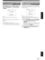
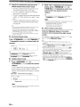
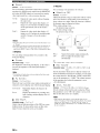
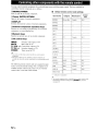
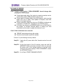
DIST
Displays the speaker distance from the listening position
in the following order:
Closest speaker distancelFarthest speaker distance
L.I.)L.
Displays the speaker output levels in the following order:
Lowest speaker output level/Highest speaker output level
Notes
• If "ERROR" appears on the video monitor during the automatic setup
procedure. measurement is canceled and the type of error is displayed.
For details, see "When an error message is displayed during
measurement" (see page 23).
• If problems occur during measurement, "WARNING (XX)" (xx indicates
the number of warning) appears above "RESULT" (see page 23).
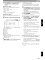
7
Press [j]ENTER.
The speaker characteristics are adjusted according to
measurement results.
To cancel the operation, press [j]Cursor <ll C> to
select "Cancel" and press [j]ENTER.
When the following screen appears, remove the
optimizer microphone. The automatic setup
procedure is now complete.
RUTO SETUP
Co~plete
[) i :=·conn€'c+.. t'1 i (.r·oP~-ll)ne
6
Press [j]Cursor Vto select "Start" and then
press [j]ENTER to start the setup procedure.
A countdown starts and a measurement starts in 10
seconds. A loud test tone is output during
measurement.
Notes
• During the automatic setup procedure, do not perform any
operation on this unit.
• To cancel the automatic setup procedure. press !TIJCursor t,.
Measurement takes about 3 minutes. To obtain
precise results, stay where you will not disturb the
measurement, such as to the side of or behind the
speakers or outside the room.
When measurement is successfully completed,
"YPAO Complete" appears on the front panel display
and the results appear on the video monitor.
.,
RESULT
r.iST;
LUL :
>5e+..
]:Selec.t
[EtHER]: Finish
[-ol]/[ ..
SF'
Displays the number of speakers connected to this unit in
the following order:
Total of Front, Center, and Presencerrotal of Surround and
Surround BackJSubwoofer
22 En
PRESS [EtHER]
[SETUP]: E:,( i t
The optimjzer microphone is sensitive to heat. Store it
in a cool place and away from direct sunlight after
measurement. Do not leave it in a place where it will be
subjected to high temperatures such on an AV
component.
,0,
~'i>~
• If you do not want to apply the measurement results, select "Cancel."
• Perform the automatic setup procedure again if you change the number
or positions of speakers.
• If you press !TIJENTER before removing the optimizer microphone.
'" Auto Setup" of "Speaker Setup" in the SETUP menu (see page 54) is
displayed.
Optimizing the speaker setting for your listening room (YPAO)
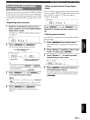
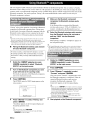
Press [DJCursor V once, and select "Retry" or
"Exit" using [DJCursor <J II> and then press
[DJENTER,.
If a problem occurs during measurement, "WARNING" is
displayed on the result display screen. Check the error and
solve the problems.
1,IRRtHt·IG
ERROF~
~
l,j-l : OUT OF PHRSE
F.:e~)t?t-·=.e
E-S:USER CRNCEL
[>on't oper.. . :ile
·::t"l':~l function
FL
CEtHEF:
SL
'=E'I
[ ... ];:[';]: Se leel
[EHTEF:] : F:ell.u--n
["4]/[ .. ] : Se leel
[Et·'TER] : F:el'.w·n
1~:E:,t.r·:::l
Performs the automatic setup procedure again.
E::< 1 t.
Terminates the measurement and the automatic setup
procedure.
ch.:lnne 1
~'~'~
• See page 75 for details on warning messages.
• Optimization will not be performed while a warning message is
displayed. We recommend that you solve the problem and perform the
automatic setup procedure again.
1
If "~" is displayed on the left of "WARNING"
on the result display screen, press
[DJENTER.
Details of the warning message are displayed. If there
are multiple warning messages, you can display the
next message using [DJCursor 1>.
2
To return to the top result display, press
[DJENTER again.
,',
~<iJ-;'
• See page 74 :for details on error messages.
• When "E-5:NOISY" appears, you can continue measurement. To
continue measurement, select "Proceed." However, we recommend that
you solve the' problem first and then perform measurement again.
I
23 En
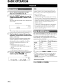
BASIC OPERATION
Playback
Note
When you play back a DTS-CD. noise may be output in some
1
2
conditions, which may cause a speaker malfunction. Make sure
Turn on external components (TV, DVD
player, etc.) connected to this unit.
that the volume is set to low before starting playback. If noise is
output, do the following.
I) When only noise is output
If a DTS bitstream signal is not properly input to this unit,
only noise is output. Connect the playback component to this
unit by digital connection and play back the DTS-CD. If the
condition is not improved, the problem may results from the
playback component. Consult the manufacturer of the
playback component.
Rotate the @INPUT selector (or press the
ffi]lnput selection keys) to select an input
source.
The name of the selected input source is displayed for
a few seconds.
Input source name
I
VOL
I II
2) When noise is output during playback or skip operation
Before playing back the DTS-CD, display the OPTION
menu after selecting the input source and set "Decoder
Mode" to "DTS" (see page 47).
11 I
- -II_I'~~
IIfl
I L' iG i 'RJ
lsi'
Sill
.:-\ci(-:
• You can change the input source name displayed on the front panel
display or on the video monitor as necessary (see page 59).
3
Play the external component that you have
selected as the source input, or select a radio
station on the tuner.
Refer to the instruction manuals provided with the
external component for details on playback. For
selecting radio stations or playback of an iPod or
Bluetooth component using this unit, see the
following.
• FM/AM radio tuning (see page 31)
• XM/SIRIUS Satellite Radio tuning (see page 33
and 37)
• Using iPod (see page 42)
• Using Bluetooth components (see page 44)
4
Turn the (QVOLUME control to adjust the
volume (or press []]]VOLUME +/-).
,--
Volume
1'--------.1.--1
I
VOL.
. ··1 ::: = ::;=:11::
II Ie
ICI·~
s'tfl
LI ellA
Sl
IS'
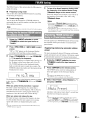
This unit has four SCENE keys that allow you to change
input sources and sound field programs with one key. A
set of input source and sound program suitable for a
certain situation, such as playing back movies or music, is
assigned to each key by default.
Input source
Sound field program
BD/DVD
HDMII
Straight
TV
AVI
Straight
CD
AV3
Straight
RADIO
TUNER
7ch Enhancer
,0,
~<il~
• This unit turns on when ~SCENE (or [IDSCENE) is pressed during
standby.
• If a Yamaha DVD player that can receive seEN E control signals is
connected to the REMOTE OUT jack of this unit. the DVD player
automatically turns all and starts playback when @SCENE (or
[IDSCENE) is pressed (see page 19). For details, refer to the instruction
manual of the DVD player.
Selecting a SCENE
Press @SCENE (or ffilSCENE).
24 En
Playback
Registering input source/sound field
program
Select the! desired input source/sound field
program, and press down @SCENE (or
rnJSCENE:) until "SET Complete" appears on the
front panE!1 display.
When the OSD is displayed on the video monitor,
"SCENE Setting Complete" appears on the video monitor.
:-'(,{~
• If you are using the remote conlrol for an external component. set that
external component too whenever SCENE setting is performed. For more
details. see Ihe next section.
You can adjust the balance of the high frequency range
(Treble) and low frequency range (Bass) of sounds output
from the front left and right speakers to obtain desired
tone.
,',
~<i>~
• The tone control of the speakers or headphones can be set separately. Set
the headphone lOne control with the headphones connected.
1
Press @TONE CONTROL on the front panel
repeatedly to select "Treble" or "Bass."
The current setting is displayed on the front panel
display.
2
Rotate the @PROGRAM selector to adjust
the output level in those frequency ranges.
Adjustable range: -10.0 dB to +10.0 dB
The display returns to the previous screen soon after
you release the selector.
Switching remotely controlled external
components linked to SCENE selections
You can operate an external component with the remote
control of this unit by setting a remote control code for the
external component for each input source. Setting remote
control codes for desired input sources allows you to
switch between external components linked to SCENE
selections.
When you change the SCENE key settings, change
settings of the external component as well by following
the steps below.
Notes
1
Register the remote control code of an
external component to the desired input
source (see page 62).
• The lone control setlings are not effective during playback in Pure Direct
mode.
• If you set the balance extremely off. sounds may not match those from
other channels well.
Note
• Remote control codes cannot be registered to TUNER, SIRIUS, or
XM inpul sources.
2
Press [§]Input selection keys on the
remote control for the input source whose
remote control code was registered in step 1
for about 3 seconds while pressing down
rnJSCIENE key whose assignment you want
to change.
The external component can now be controlled
remotely just by selecting the rnJSCENE key.
Use Pure Direct mode to enjoy the pure high fidelity
sound of the selected source. When Pure Direct mode is
activated, this unit plays back the selected source with the
least circuitry.
Press @PURE DIRECT (or [IDPURE DIRECT)
to turn the Pure Direct mode on or off.
The following features are disabled in Pure Direct mode.
- sound field program and tone control
- display and operation of the OPTION menu and
SETUP menu
- multi-zone function
~\~/-:.
1
Press [ll]MUTE on the remote control to mute
the audio output.
The MUTE indicator on the front panel display
flashes while audio output is muted.
2
Press [ll]MUTE again to resume audio
output.
• The front panel display lurns off in Pure Direct mode. It turns on again
when Pure Direct mode is turned otf.
25
En
•
Playback
~~Di"Jl;'li1iilo1ii/atililrili;"fiJflli;;nt
Plug your headphones in the @PHONES jack on
the front panel.
When you select a sound tield program while using the
headphones, the mode is automatically set to SILENT
CINEMA mode.
Notes
• When you connect headphones. no signals are output from the
SPEAKERS terminals.
• When multi-channel signals are processed. sounds in all channels are
divided to left and right channels. When the input source is set to
"MULTI CH:' only front UR sound is output from the headphones.
When HOMII-4 or AVI-4 is selected as the input source,
you can display audio/video signal information.
,0,
~<il~
• Input signal information is displayed on both a video monitor and the
front panel display.
1
Select the desired input source, and press
IIIDOPTION.
:1l~~~t~tSIJ!!!"';~ ,'.
• Currently selected input source name (Input)
• Currently selected sound field program name (OSP
Program)
• Currently selected surround decoder (Audio Decoder)
• Currently set FM/AM tuner frequency (Frequency)
• XM/SIRIUS tuner information (Channel, Category,
Artist/Song, Antenna, Composer)
• iPod playback information (Song, Album, Artist, List)
For example, if you select HOMll and display "OSP
Program," the following screen appears on the front panel
display.
Input source
I
:····.L
.::. i... r·.~
I
Press !TIJCursor fJ. I V to select "Signal Info,"
and press !TIJENTER.
Information on input signals is displayed. See
page 47 on information displayed on the screen.
,0,
~<il~
• You can change ilems of information displayed on the fronl panel
display using illJCursor fj I V.
• If an HOM I related error occurs. error information is displayed at
the bottom of the screen.
3
To end the information display, press
IIIDOPTION.
.
You can display information on the front panel display
such as the names of the currently selected sound field
program and surround decoders on the front panel display.
To change the display, press ®INFO (or [I]INFO)
repeatedly. The following information can be displayed on
the front panel display.
The OPTION menu for the selected input source is
displayed (see page 46).
2
,.'.
.... : :
],
=:::1 n T..
I
I
Sound field program (OSP program)
The information on each input source that can be
displayed is shown in the table below.
Input source
Items
HOMII-4
AVI-6
AUDIOI-2
V-AUX
Input
DSP Program
Audio Decoder
MULTICH
Input
FM/AM
Frequency
DSP Program
Audio Decoder
XM
SIRIUS
Channel
Category
Artist/Song
Composer (SIRIUS only)
Antenna
DSP Program
Audio Decoder
iPod
(Simple remote mode)
Input
DSP Program
Audio Decoder
iPod
(Menu browse mode)
(Play information display)
Artist
Album
Song
DSP Program
Audio Decoder
(Play menu display)
List
Bluetooth
26 En
. ..'
Input
DSP Program
Audio Decoder
Enjoy the sound field programs
This unit is also equipped with a Yamaha digital sound field processing (DSP) chip. You can enjoy multi-channel sounds
for almost II input sources using various sound field programs stored on the chip and a variety of surround decoders.
•
Selec1ting a sound field program on the front panel
Rotate the ~2)PROGRAM selector to select a desired sound field program.
•
Selec1ting a sound field program with the remote control
Perform the following operations depending on the category of the sound field programs.
Sound field programs for moviesrrV programs
Press [IDMOVIE repeatedly.
Sound field programs for music
Press [IDMUSIC repeatedly.
Stereo reproduction
Press [IDSTEREO repeatedly.
Multi-channel stereo reproduction
Press [IDSTEREO repeatedly.
Compressed Music Enhancer
Press [IDSTEREO repeatedly.
Surround decoder
Press [IDSUR. DECODE repeatedly.
For exampk, if you select "Sci-Fi" in "MOVIE," the following screen appears on the front panel display.
Sound field program category
I
1"1 I I I' I I
IIUI' 1. c..:
1"'•
OM
.....
l.:::i.....:.
: ••
•
":
:~
Program name
Notes
Sound field programs are stored for each input source. When you change the input source. the sound lield program previously selected for that input
source is applied again.
When you play back the Dolby Digital Plus. Dolby TrueHD. DTS Express, DTS-HD Master Audio, or DTS-HD High Resolution Audio sources, sound is
reproduced ill straight decode mode.
If the sampling frequency of an input source is higher than 96 kHz. this unit does not apply any sound lield programs.
o
o
o
Sound field program descriptions
This unit provides sound field programs for multiple categories including music, movies and stereo reproduction. Select
a sound field program based on your listening preference, not merely on the name of the program, etc.
,',
O<j)~
o
o
o
You can check what speakers are currently outputting signals with the speaker indicators 011 the front panel display (see page 6).
Each program can adjust sound field elements (sound field parameters). For details, see page 49.
ICONEMA!:Z:::!iI in the table indicates the sound field program with CINEMA DSP.
For moviefTV program sources (MOVIE)
IC I N EMAj"lij'kJ
Descriptions
Standard
Creates a sound field that emphasizes the surrounding feeling without disturbing the original acoustic positioning
of multi-channel audio such as Dolby Digital and DTS. The design concept of this sound lield is "an ideal movie
theater," in which the audience is surrounded by beautiful reverberations from Ihe left, right and rear.
Spectacle
Creates a speclacular sound tleld Ihal produces a sense of magnitlcent scale. This sound tleld program fealUres a
wide dynamic range Ihat reproduces a broad theater sound field malching cinemascope and wider-screen movies.
from tiny sound effects
Sci-Fi
10
big acoustics.
Creates a clear sound tield Ihat allows you to enjoy the tlnely elaborated sound design of the latest science tlction
and SFX movies. Different atmospheres can be vividly reproduced while dialog. sound etfects and background
music are clearly separated.
Adventure
Creates a sound field ideal for action and adventure movies. reproducing a sense of power by reducing
reverberations and emphasizing a horizontal soundscape. A clear and powerful almosphere is reproduced while
I
maintaining separation of audio channels and sound clarity with a shallower depth of feeling.
27
En
Enjoy the sound field programs
Program
Drama
Descriptions
Creates a calm sound field suitable for different genres of movies, from serious dramas to musicals and comedies.
Sound is produced with discreet reverberation yet with a three-dimensional feeling. Spatial sound effects and
background music are reproduced with soft reverberations around the center position. which reduces fatigue from
watching movies for a long time.
Mono Movie
Creates a sound field that allows you to enjoy old monaural movies in an atmosphere of a movie theater of those
days. A comfortable space with a feeling of depth is reproduced by adding soundscape and reasonable
reverberation to the original sound.
Sports
Creates a lively sound field suitable for stereo sports broadcasts and TV studio shows. In sports broadcasts, the
voices of sports commentators and analysts are output from the center while the crowd's cheers and other sounds
are suitably spread out, creating a realistic stadium atmosphere that makes you feel as if you are really there.
Action Game
Creates a sound field designed for action games such as car racing and FPS games. The presence of various sound
effects is enhanced while maintaining a clear feeling of direction by limiting each channel's sound effect range
using reflection data. which produces a realistic and powerful playing environment.
Roleplaying Game
Creates a sound field designed for roleplaying games and adventure games. Depth and a three-dimensional feel to
the game are produced by combining movie sound field effects and the sound design used in "Action Game." In
movie scenes. movie-like surround etlects are produced.
For audio music sources (MUSIC)
ICINEMA"l"\!Q'ilI
Program
Hall in Munich
Descriptions
Creates a sound tield designed by simulating a concert hall with about 2,500 seat in Munich, which is a typical
European concert venue with elegant wooden interior walls. A rich. delicate and beautiful sound is produced.
creating a relaxing atmosphere. The seat sctting is a left center orchestra seat.
Hall in Vienna
Creates a sound field designed by simulating a concert hall with about 1,700 seats in Vienna. which is a traditional
middle-size shoebox type concert venue. In this hall, complex omnidirectional reflections bounce off pillars and
carvings to produce a characteristically rich sound.
Chamber
Creates a sound field designed by simulating a relatively large room with a high ceiling such as a palace chamber.
It produces pleasant reverberations suitable for court music and chamber music.
Cellar Club
Creates a realistic live sound field designed by simulating a live house with a low ceiling and intimate atmosphere.
It features a powerful sound that makes you feel as if you are right in front of a small stage.
The Roxy Theatre
Creates a sound tield designed by simulating a rock music live house with up to about 460 seats in Los Angeles.
The seat setting is a left center seat.
The Bottom Line
Creates a sound field designed by simulating "The Bottom Line," a famous New York jazz club which has a tloor
occupied by 300 wide seats. It produces clear reverberations. The seat setting is in front of the stage.
Music Video
Creates a sound field designed by simulating a concert venue where live performances of pop, rock and jazz music
lake place. You can indulge yourself in a hOI live atmosphere created by a presence sound field that emphasizes the
vividness of vocals and solos and the beat of the drums, and by a surround sound field that reproduces a big live
venue atmosphere.
For stereo reproduction (STEREO)
Descriptions
Program
2ch Stereo
Produces front stereo sound. This is standard playback mode.
~\ri:~
• When multi-channel signals are input. they are downmixed to 2 channels and output from the front left and right speakers.
For multi-channel stereo reproduction (STEREO)
Program
7ch Stereo
Descriptions
Produces front and rear sound for a large area. This playback mode is suitable for BGM at a house party. Sound is
output from a maximum of seven speakers.
28 En
ICINEMA"l"\!Q'ilI
Enjoy the sound field programs
The Compressed Music Enhancer (ENHNCR)
Program
Straight Enhancer
Descriptions
Dynamically reproduces sound from 2-channel or multi-channel compressed sound data with the same number of
channels as its source sound.
7ch Enhancer
Dynamically reproduces sound from compressed sound data in 7 channels regardless of the source sound channels.
Surround decode mode (SUR. DEC)
Reproduces sound from 2-channel sound sources in up to 7 channels using a surround decoder.
Decoder
Descriptions
Pro Logic
Reproduces sound using the Dolby Pro Logic decoder. This is suitable for all kinds of sound sources.
PLllx Movil~1
PLII Movie
Reproduces sound using the Dolby Pro Logic [Jx (or Dolby Pro Logic II) decoder. This is suitable for movies. You
cannot select the Dolby Pro Logic IIx decoder in the following conditions:
• When no surround back speakers are connected
• When headphones are connected
PLllx Music I
PLII Music
Reproduces sound using the Dolby Pro Logic fIx (or Dolby Pro Logic II) decoder. This is suitable for music. You
cannot select the Dolby Pro Logic IIx decoder in the following conditions:
• When no surround back speakers are connected
• When headphones are connected
PLllx Gamel
PLII Game
Reproduces sound using the Dolby Pro Logic Ilx (or Dolby Pro Logic II) decoder. This is suitable for games. You
cannot select the Dolby Pro Logic IIx decoder in the following conditions:
• When no surround back speakers are connected
• When headphones are connected
Neo:6 Cinema
Reproduces sound using the DTS Neo:6 decoder. This is suitable for movies.
Neo:6 Music
Reproduces sound using the DTS Neo:6 decoder. This is suitable for music.
Neural Sur.
(U.S.A. model only)
Performs Neural Surround processing for all sound sources.
The Neural Surround decoder supports PCM (sampling rate of 96 kHz or lower), Dolby Digital, DTS Digital
Surround (except for DTS 96/24), DSD and analog 2-channel input sources. When the Neural Surround decoder is
selected and an unsupported signal is input, a multi-channel sound source is directly decoded to an appropriate
channel without performing any additional effect processing. A Neural Surround incompatible PCM sound source
is reproduced in stereo. The Neural Surround decoder is especially suitable for the XM HD Surround program of
XM Satellite Radio.
,0,
~<i>~
• When multi·channel sound is input. sound is reproduced in straight decoding mode (see page 30).
I
29 En
Enjoy the sound field programs
_.. : T i 0""0 .. . ,.
~.
In straight decoding mode, sounds are reproduced without
sound field effect. 2-channel stereo sources are output
from only the front left and right speakers. Multi-channel
input sources are decoded straight into the appropriate
channels and multi-channel sounds are reproduced
without a sound field effect.
1
To enable straight decoding mode, press
®STRAIGHT (or rn:JSTRAIGHT).
SILENT CINEMA allows you to enjoy multi-channel
sources with your headphones. SILENT CINEMA mode
is automatically selected when you connect the headphone
plug to the PHONES jack.
Note
• SILENT CINEMA mode is not available in the following conditions.
- 2ch Stereo of the sound field program is selected.
- Pure Direct mode or straight decoding mode is selected.
"Straight" appears on the front panel display.
2
To cancel straight decoding mode, press
®STRAIGHT (or rn:JSTRAIGHT) again.
A sound field program name appears on the front
panel display, and sound is reproduced with that
sound field effect.
Virtual CINEMA DSP allows you to enjoy DSP sound
field surround effects even without any surround speakers
by using virtual surround speakers. You can even enjoy
Virtual CINEMA DSP using a minimal two-speaker
system that does not include a center speaker.
When "Sur. LlR SP" in the SETUP menu is set to "None"
(see page 55), this unit operates in Virtual CINEMA DSP
mode.
Note
• Virtual CINEMA DSP is not available in the following conditions even if
you set "Sur. LlR SP" to '·None·· (see page 55).
- headphone plug is connected 10 the PHONES jack.
- 7ch Stereo of the field sound program is selected.
- Pure Direct mode or straight decoding mode is used.
30 En
CINEMA DSP 3D mode creates an intensive and accurate
stereoscopic sound field in the listening room.
To use this unit in CINEMA DSP 3D mode, presence
speakers are required. Do the following steps and then
select a CINEMA DSP sound field program. When a
sound field program runs in CINEMA DSP 3D mode, the
CINEMA DSP 3D indicator on the front panel lights up.
• Connect the presence speakers to the EXTRA SP jacks
(see page 12).
• Set "Extra SP Assign" to "Presence" (see page 54).
• Enable CINEMA DSP 3D in the SETUP menu
(see page 49).
Note
• If headphones are connected to Ihis unit, this unit plays back in SILENT
CINEMA mode so CINEMA DSP 3D mode cannot be enabled.
FM/AM tuning
The FM/AM tuner of this unit provides the following two
modes for tuning.
4
•
Frequency tuning mode
You can tune into a desired FM/AM station by searching
or specifying its frequency.
•
Preset tuning mode
You can preset the frequencies of FM/AM stations by
registering them to specific numbers, and later just select
those numbers to tune in.
Notes
• When you press [j]Numeric keys during preset tuning. a
preset number is selected. Set tuning mode to frequency tuning
mode using CDTUNING/CH <11 C> (or [§]TUN./CH f:::, 1 'V)
prior to the operation.
• "Wrong Station'" appears on the front panel display when you
enter a frequency that is out of receivable range. Make sure that the
entered frequency is correct.
Note
• Adjust the FM/AM antennas connected to this unit for the best reception.
Rotate the @INPUT selector (or press
ffi]TUNER) to switch the input source to
"TUNER,"
2
3
Press eDFM ([§JFM) or eDAM ([§JAM) to select
a band.
"FM" or "AM" appears on the front panel display
according to the band that you have selected.
Press Q)TUNING/CH <J II> (or [§JTUN./CH
1:11 \7) to specify the frequency.
To adjust the frequency to a higher range, press I> (or
You can register up to 40 FM/AM stations (Preset) using
the automatic station preset feature or manual station
preset feature.
Registering stations by automatic station
preset
The tuner automatically detects FM stations with strong
signals and registers up to 40 stations. AM stations cannot
be automatically registered. Use manual station preset.
1
Rotate the@INPUT selector (or press
ffi]TUNER) to switch the input source to
"TUNER."
2
Press IIIDOPTION on the remote control.
The OPTION menu screen for setting options of
tuner input appears on the front panel display.
1:1). To adjust it to the lower range, press <J (or \7).
The TUNED indicator on the front panel display
lights up when the tuner is tuned into a station. The
STEREO indicator also lights up if the program being
broadcasted is in stereo.
C
STEREO
TUN;.~.. r,'::: •
r- i'i ..,' Ir:.. :: ::::: i'i
i···: '::'
___________
,_=_=_1_._1-_,
i'''' i'.'i
To tune in by direct frequency tuning, enter
the frequency of the desired station using
IJ]]Numeric keys on the remote control.
Enter only integers. For example, if you want to set
the frequency to 88.9 MHz, enter "889" using
IJ]]Numeric keys.
'"
~"'~
;".,-..: .....:
• For details on the OPTION menu, see page 46.
• The OPTION menu is displayed on the video monitor.
_
The frequency changes in the following manner according
to how you press Q)TUNING/CH <J II> (or [§JTUN.I
CH 1:11 \7).
3
Select "Auto Preset," using ITIJCursor
and press ITIJENTER.
1:11 \7
When yOLi press the key more than 1 second
The tuner searches the frequency of a station that is
detectable around the current frequency. This is effective
when the tuner can receive strong signals without any
interference. Once the search starts, release the key.
Automatic station preset starts about 5 seconds later
from the lowest frequency upwards.
When you press and release the key
The tuner increases or decreases the frequency in steps.
Use this method when the tuner cannot receive strong
signals and stations are skipped during the search.
• You can select the preset number at which the preset starts by
pressing [§]PRESET f:::, 1 'V or [llJCursor f:::, 1 'V on the remote
control while "READY" is displayed on the from panel display.
• To cancel registration. press [llJRETURN on the remote control.
:fi{-:.
~'4r-:.
• You can switch between stereo and monaural for FM broadcast in the
OPTION menu (see page 48).
31
•
En
FM/AM tuning
Status
Calling a preset station (Preset tuning)
You can call preset stations registered by automatic station
preset or manual station preset.
Preset number
Frequency
During the automatic station preset, the upper area of
the screen changes as follows: SEARCH ~
MEMORY each time a station is registered.
When registration is complete, "FINISH" appears
and the OPTION menu screen automatically
reappears. When you press IIIDOPTION on the
remote control, the screen returns to the original state.
Registering stations by manual station
preset
You can manually register AM stations or FM stations
with weak signals.
1
Tune into a station referring to "Tuning into
the desired FM/AM station
(Frequency tuning mode)" (see page 31).
2
Press @MEMORY (or [IDMEMORY).
"Manual Preset" appears on the front panel display,
followed soon by the preset number to which the
station will be registered.
Press @PRESET <J / [> (or [IDPRESET
select a preset number.
,0,
~<il~
• Preset numbers to which no stations are registered will be skipped.
• If no stations are registered, "No Presets" or "No Presets in Memory"
appears on the display. See page 31 and register stations.
• You can directly select a preset number by pressing a IrnNumeric
keys while calling a preset station. "Empty" appears on the display if
you enter a preset number to which no station is registered. "Wrong
Num." appears if you enter an invalid number.
• When you press IrnNumeric keys during normal tuning, a preset
number is selected. Set tuning mode to preset tuning mode using
@PRESET <J I r> (or [§]PRESET f::" I II) prior to the operation.
Clearing the preset station
1
Rotate the @INPUT selector (or press
ffi]TUNER) to switch the input source to
"TUNER."
2
Press IIIDOPTION on the remote control.
The OPTION menu screen for setting options of
tuner input appears on the front panel display.
3
,0,
The following screen appears on the display.
• By pressing down@MEMORY (or [§]MEMORY) for more
than 2 seconds, you can skip step 3 and register the station to the
lowest empty preset number or a preset number one higher than the
last preset number.
Press @PRESET <J / [> (or [IDPRESET 6./
V) to select the preset number to which the
station will be registered.
When you select a preset number to which no station
is registered, "Empty" appears on the display. When
you select a registered preset number, a registered
frequency is displayed on the right of the preset
number.
Frequency to be registered
1=-=--------------
~ J I__
I
:_:: -:-;
1_'_1
rc~~tl : ,~i:'! !~:·1~~.,--------,
;
Flashing
Preset
number
i
Empty (or frequency that is currently
registered to the preset number)
,',
:(j)-:
• You can select a preset number using the IrnNumeric keys.
4
Press @MEMORY (or [IDMEMORY) again to
register.
When registration is complete, the screen returns to
the original state.
,0,
~<il~
• To cancel registration. press [J]RETURN on the remote control
or leave the tuner wilhout any operations for about 30 seconds.
32
En
Display "Clear Preset" using the illJCursor
6. / 'land press illJENTER.
~<il~
3
6./ V) to
I
Preset number of the registered station you want to clear.
,0,
~<il~
• You can cancel the operation and return to the OPTION menu
screen by pressing [J]RETURN on the remote control.
4
Select the preset number of the registered
station you want to clear using the illJCursor
6. / 'land press illJENTER.
The preset station registered to the selected preset
number is cleared. To clear the registration of
multiple preset numbers, repeat the above steps.
To end the operation, press IIIDOPTION.
XM® Satellite Radio tuning (U.S.A. model only)
Listening to Satellite Radio
To listen to Satellite Radio, you'll need to connect either a SIRIUS or XM Satellite Radio tuner (sold separately) to your
satellite-ready receiver. Satellite Radio is available to residents of the US (except Alaska and Hawaii).
Satellite Radio delivers a variety of commercial-free music from categories ranging from Pop, Rock, Country, R&B,
Dance, Jazz, Classical and many more plus coverage of all the top professional and college sports including play by play
games from select leagues and teams. Additional programming includes expert sports talk, uncensored entertainment.
comedy, family programming, local traffic and weather and news from your most trusted sources.
Whether you purchase a SIRIUS or XM tuner, you'll need to activate and subscribe to begin enjoying the service. Easy to
follow installation and setup instructions are provided with the satellite tuners. Whichever service you choose, there are a
variety of programming packages available, including the option of adding "The Best of SIRIUS" programming to your
XM tuner or 'The Best of XM" programming to your SIRIUS tuner, enabling you to enjoy the most popular
programming among both services. The "Best of' packages are not available to SIRIUS or XM Canada subscribers at
this time. Family friendly packages are also available to restrict channels featuring content that may be inappropriate for
children.
To subscribe to XM, U.S. customers should visit xmradio.com or call 1-800-XMRADIO (1-800-967-2346).
To subscribe to SIRIUS, U.S. customers can call 1-888-539-SIRI (1-888-539-7474) or visit sirius.com (US).
SIRIUS XM Radio Legal
SIRIUS, XM and all related marks and logos are trademarks of Sirius XM Radio Inc. and its subsidiaries. All other
marks and logos are the property of their respective owners. All rights reserved. SIRIUS and XM subscriptions sold
separately. Taxes and a one-time activation fee may apply. XM tuners and home docks or SIRIUS tuners (each sold
separately) are required to receive the SIRIUS or XM satellite radio service. All programming and fees subject to
change. It is prohibited to copy, decompile, disassemble, reverse engineer, hack, manipulate or otherwise make
available any technology or software incorporated in receivers compatible with the SIRIUS or XM Satellite Radio
Systems. Service not available in Alaska and Hawaii.
Notes
Connect XM Mini-Tuner and XM Mini-Tuner Home
Dock (sold separately) to the XM jack on the rear panel of
this unit. For details, see the instruction manuals provided
with the XM Mini-Tuner Home Dock.
• If "CHECK ANTENNA." "CHECK XM TUNER" or "NO SIGNAL"
appears on the front panel display. the connection and setting of the
antenna. XM Mini-Tuner Home Dock. or XM Mini-Tuner may not be
correct.
• When "UPGRADE XM TUNER" is displayed. it means that the
connected antenna is old. See page 70 for details.
Once you have installed the XM Mini-Tuner Home Dock,
inserted the XM Mini-Tuner, connected the XM MiniTuner Home Dock to your XM Ready® home audio
system, and installed the antenna, you are ready to
subscribe and begin receiving XM programming. You can
find your eight character XM Radio 10 on the XM MiniTuner, on the XM Mini-Tuner package, or on XM Channel
O. Write down the XM Radio ID in the eight squares
provided below for future reference.
XM Mini-Tuner and XM Mini-Tuner Home Dock
(sold separately)
DDDDDDDD
Note
,"
~<i>~
• To ensure optimal reception of the XM Satellite Radio signals, the XM
Mini-Tuner Home Dock must be placed at or near a southerly facing
window with no obstacles in the path to the sky. You can mount it indoors
or outdoors. Use the "Antenna" information on the front panel display or
on the video monitor (see page 36) to check the antenna reception level
and adjust the orientation of the antenna.
• The XM Radio ID does not use the lellers "I," "0." "S" or "F." Activate
your XM Satellite Radio service in the U.S. online at http://
activate.xmradio.coml or call 1-800-XM-RADI0 (1-800-967-2346). You
will need a major credit card. XM will send a signal from the satellites to
activate the full channel lineup. Activation normally takes 10 to 15
minutes. but during peak busy periods you may need to keep your XM
Ready home audio system on for up to an hour. When you can access the
full lineup on your XM Ready home audio system you are done.
33 En
•
XM® Satellite Radio tuning (U.S.A. model only)
•
Category Search mode
1
Press ([)CATEGORY <:] 1 C> (or
[§]CATEGORY <:] 1 C» to select the channel
Rotate the ®I NPUT selector (or press
[IDXM) to select "XM" as the input source.
The XM Satellite Radio information (such as channel
number, channel name, category, artist name and
song title) for the currently selected channel appears
on the front panel display and video monitor
(see page 36).
category.
"CAT" is displayed on the front panel display during
the channel category selection. When you select the
category, the first channel in the category is selected.
Category
search mode
j
[g....
_ 1--1-----------------
:
:
Category ~-a-m-e---------------
Note
Channel name
• If you don't operate within 10 seconds. the category search mode
returns to "ALL'" (All Channel Search mode).
'"
~<i>~
• When you select "XM'" as the input source. this unit automatically
calls the previously selected channel.
2
While "CAT" is displayed on the front panel
display, press Q)TUNING/CH <:] 1 C> (or
[§]TUN./CH /::, 1 'V) repeatedly to search for a
channel within the selected channel
category.
Note
• If a status message or an error message appears on the front panel
display or on the video monitor. see "XM Satellite Radio'"
(see page 70).
Search for a channel by using one of the XM
Satellite Radio search modes.
• To select a channel from the all channel list, see
"All Channel Search mode" on this page.
• To select a channel by category, see "Category
Search mode" on this page.
• To select a channel directly by entering the channel
number, see "Direct number access mode" on this
page.
• To select a channel from the preset channels, see
"Calling a preset channel (Preset Search mode)"
(see page 35).
,"
~<i>~
• You can display the XM Satellite Radio information on the front
panel display or on the OSD (see page 36).
• You can set the XM Satellite Radio preset channels (see page 35).
•
All Channel Search mode
Press Q)TUNING/CH <:] 1 C> (or [§]TUN./CH 61
'V) repeatedly to search for a channel within all
channels.
e=f::I:= ....
I•••:::••:
.:::'
'"
~<i>~
• You can search for a channel quickly by pressing and holding
Q)TUNING/CH <J II> (or !IDTUN./CH 6 I 'J).
• You can skip channels to the previous or next category by pressing
(])CATEGORY <J II> (or !IDCATEGORY <J 11».
34 En
--------,
i..: :-::::.
~~:~~j -1- -P
r' ~~ !",= j, E:~ 1,=,1
----lj----------
2
1:::-:-:-
MI-U I'I'II'IU
I_I I I .I!...I!!....I I
Search mode
Channel nuri,ber
The first channel in the category
:\(,{-:..
• You can search for a channel quickly by pressing and holding
Q)TUNING/CH <J II> (or !IDTUN./CH 6 I Il)
Note
• This unit skips the following channels in All Channel Search mode
or Category Search mode. This is not a malfunction.
- channels that are not currently in service
- channels that you do not subscribe to
•
Direct number access mode
Press the IllINumeric keys on the remote
control to enter the desired three-digit channel
number.
For example, to enter the number 123, press" I," "2" and
then "3" of the IllINumeric keys.
~\ci{-:..
• To display the Radio ID number on the front panel display, select channel
'"0."
• When entering a one-digit or two-digit channel number. enter the number
using the IillNumeric keys and then press IillENT on the remote
control to confirm your entry.
• This unit automatically accepts your entry if you do not press IillENT
within a few seconds after entering the number.
• If the selected channel is not available. an advisory message may appear.
For details, see "XM satellite radio" on page 70.
• If this unit is in preset search mode (see next page), a preset number is
selected instead of a channel number when you press the IillNumeric
keys. To switch to direct number access mode, press Q)TUNING/CH
<J II> (or !IDTUN./CH 6 Ill).
XM@ Satellite Radio tuning (U.S.A. model only)
Calling a preset channel (Preset Search
mode)
You can use this feature to store up to 40 XM Satellite
Radio channels. You can call any preset channel just by
selecting a preset number as described in "Calling a preset
channel (Preset Search mode)" on this page.
Prior to selecting a preset number in Preset Search mode,
you must register an XM Satellite Radio channel to the
preset number. For details, see "Registering preset
channels" on this page.
Preset number
Registering preset channels
XM
1
Search for a channel you want to set as a
preset channel in one of the XM Satellite
Radio search modes.
For details, see "XM Satellite Radio operations"
(see page 34).
I
1--' IJ :
eo : : : .
::..:=:.: :..:
Press (8)PRESET <J / C> (or [IDPRESET 6./ \/)
repeatedly to change preset numbers (1 to 40).
~(j{-:
• You can directly enter the preset number using the [j]]Numeric keys
instead of selecting it using (8)PRESET <J I C> (or [§]PRESET /:, I
1/).
2
Clearing preset channels
Press @MEMORY (or [IDMEMORY).
The front panel display changes as follows.
You can clear the assignments of preset XM Satellite
Radio channels.
Currently registered channel
(or " •••" if empty)
XM
1----------I
PI] 1:-- -- 1. <: <: 001;:::- - - - -
1
Press [IDOPTION on the remote control.
The OPTION menu is displayed on the front panel
display.
2
Press ITIJCursor \/ repeatedly to select "Clear
Preset" and then press ITIJENTER.
3
Press ITIJCursor 6. / \/ to select the preset
channel that you want to clear.
1"1 C 1"11-1 CI "
I
III_I II_II'
'--------"""--"I
Presel number
Channel to be registered to the
selected preset number
,"
':(j)':
• To register the selected channel under an empty preset number
automatically, press and hold @MEMORY (or [§]MEMORY)
for more than 2 seconds instead of doing step 2. In this case, steps
3 and 4 are unnecessary.
• To cancel the preset operation, press !DJRETURN.
3
Press (8)PRESET <J / c> (or [IDPRESET
\/) to select the preset number.
• You can also select a preset number by pressing Ihe [j]]Numeric
keys.
Press@MEMORY(or [IDMEMORY).
The channel is registered to the selected preset
number.
1_ I_I "I
6./
Note
4
I ,.' , u'u" ,
:;i:: 0 I~J ;::; ;:; 0 : : : .
4
I!...J
I
Press ITIJENTER to execute the clearing of
the selected preset channel.
To clear the registration of multiple preset channels,
repeat the above steps. To end the operation, press
[IDOPTION.
I
35 En
XM@ Satellite Radio tuning (U.S.A. model only)
•
Video monitor (050)
Press IWIDISPLAY on the remote control to turn
on or off the information display.
You can display the XM Satellite Radio information on
the front panel display or on the video monitor.
The following information is displayed on the video
monitor.
Note
•
CD
Front panel display
Channel category, channel number
f
I
--1'
1 !
'1'
~:i 171 :=:: ' :=: ~:1·=.
'-'Ii
I_·n
- t· -I.
':1I::ld.
'I_,r I
,- -
1I ®
@----"'j:De':.ade::.
R: :;,:'InW'p:,!"IO --------+- ®
I
Press ®INFO (or [IJINFO) repeatedly to toggle
the XM Satellite Radio information display modes
as shown below.
Channel number, channel name
I~jl·..j'r: 1II·!t- @
::.:}'j
• II' a status message or an error message appears on the front panel display
or the video monitor, see "XM Satellite Radio" (see page 70).
@ __
<D
®
/:i:""'I.::,.J
"'. _ ..I.J
'1...
'.,"', ,It"!"·j'i.:'
1_ '" .j
Search mode (see page 34)
Channel category
@
@
Song title
®
®
:*-=-
Channel number/name
Antenna reception level
Artist name
• To turn off the OSD. press @JDISPLAY.
• You can hold the music information screen or release it by ITIJENTER,
fk·+"i:=.t.. . . . Son'3
Artist name, song title, channel number
Antenna reception level, channel number
Current sound field program (see page 27), channel
number
Current Audio Decoder (see page 29), channel number
Back to "Ch:inne 1"
Front Panel Display (example)
XM
Hi_ UJ IJ l:i
t.
r~ n !:~ !'''j n.:l
'T'lllill"
:'cj{-:
• If the XM Satellite Radio information contains a character that this unit
cannot recognize. the character is replaced by a blank .
• When an information is unavailable. " - " appears.
36 En
SIRIUS Satellite Radio™ tuning (U .S.A. model only)
Displaying the Sirius 10 of your
SiriusConnect tuner
Connect the SiriusConnect tuner (sold separately) to the
SIRIUS jack on the rear panel of this unit. For details, see
the instruction manuals provided with the SiriusConnect
tuner.
SiriusConnect Tuner and the antenna
(sold separately)
1
Rotate the @INPUT selector (or press
[IDSIRIUS) to select "SIRIUS" as the input
source.
2
Press illiG and then IllIENT to display the
Sirius 10 of your SiriusConnect tuner.
"000 Sirius 10" and "xxxxxxxxxxxx"
("xxxxxxxxxxxx" indicates the 12-digit Sirius ID of
your SiriusConnect tuner) appears alternately on the
front panel display,
Write down the Sirius ID in the space provided
below.
To the AC wall outlet
10:
_
'"
~'il~
• To ensure optimal reception of the SIRIUS Satellite Radio signals, the
antenna of the SiriusConnect tuner must be placed at or near a window
with no ob~tacles in the path to the sky. The orientation of the antenna for
the best reception differs depending on the area. Refer to the instruction
manuals provided with the SiriusConnect tuner for the installation of the
antenna. You can mount it indoors or outdoors.
• Use the Antenna information on the front panel display or the SIRIUS
information screen on the video monitor (see page 41 ) to check the
antenna reception level and adjust the orientation of the antenna.
• You need 10 connect the SiriusConnect tuner to the AC wall outlet.
3
SIRIUS Satellite Radio online information
Contact for activation
URL: https://activate.siriusradio.comi
Phone: 1-888-539-SIRIUS (1-888-539-7474)
.:-\(,{~
Notes
• Status messages appear on the front panel display or the video
monitor during the activation. For details, see "SIRIUS Satellite
Radio" (see page 71). Once the activation is finished, "SUB
UPDATED" appears.
• If "CHECK SR TUNER" or "ANTENNA ERROR" appears on the front
panel display, the connection of the SiriusConnect tuner or antenna is
incorrect. In such cases, check the connection of the SiriusConnect tuner
and the antenna.
• If "NOT SUPPORTED" appears on the front panel display, this unit does
not support the connected SiriusConnect tuner.
1
Before using the SIRIUS Satellite Radio feature, you need
to activate your SIRIUS Satellite Radio subscription. To
activate the subscription you need the Sirius 10 which is
uniquely assigned to the SiriusConnect tuner. Sirius 10 is
12-digit number and it appears on the package of the
SiriusConnect tuner, on the label of the SiriusConnect
tuner, and when you tune into the SIRIUS Satellite Radio
channel "0" (see next section).
Contact SIRIUS Satellite Radio to activate
your subscription.
Rotate the @INPUT selector (or press
[IDSIRIUS) to select "SIRIUS" as the input
source.
The cursor on the left of the SIRIUS indicator lights
up on the front panel display and the SIRIUS Satellite
Radio information (such as channel number, channel
name, category, artist name, or song title) for the
currently selected channel appears on the front panel
display.
Search mode
SIRIUS
1 II I
1"11- 1_
l:::::4
,
i
Channel number
I
Channel name
,0,
~'il~
• When you select "SIRIUS" as the input source, this unit
automatically calls the previously selected channel.
Notes
• Before activating your subscription, you can only select "184" or
"000."
• If a status message or an error message appears on the front panel
display or on the OSD on the video monitor, see "SIRIUS Satellite
Radio" (see page 71).
37
En
I
SIRIUS Satellite Radio™ tuning (U.S.A. model only)
2
Search for a channel by using one of the
SIRIUS Satellite Radio search modes.
2
• To select a channel from the all channel list, see
"All Channel Search mode" on this page.
• To select a channel by category, see "Category
Search mode" on this page.
• To select a channel directly by entering the channel
number, see "Direct number access mode" on this
page.
• To select a channel from the preset channels, see
"Calling a preset channel (Preset Search mode)"
(see page 39).
'"
~<il~
• You can search for a channel quickly by pressing and holding
Q)TUNING/CH <:11 t> (or [IDTUN./CH !J. 1 'V).
Note
• This unit skips the following channels in All Channel Search mode
or Category Search mode. This is not a malfunction.
- channels that are locked (see page 40)
- channels that are not currently in service
- channels that you do not subscribe to
,"
~<il~
• You can display the SIRIUS Satellite Radio information on the
front panel display or the video monitor (see page 41 ).
• If you tune inlo a channel that you do not subscribe, "CALL
SIRIUS on the front panel display" or "CALL 888-539-SIRIUS
TO SUBSCRIBE" on the video monitor appears.
• You can register SIRIUS Satellite Radio channels to the preset
oumbers (see page 39).
•
All Channel Search mode
Press Q)TUNING/CH <J I C> (or [IDTUN./CH ~ I
IJ) repeatedly to search for a channel within all
channels.
.j
.I.
,',
~<il~
• You can search for a channel quickly by pressing and holding
Q)TUNING/CH <:11 t> (or [IDTUN./CH !J. 1 'V).
• You can skip channels to the previous or next category by pressing
([)CATEGORY <:11 t> (or [IDCATEGORY <:11 t».
•
Category Search mode
1
Press CDCATEGORY <J I C> (or
[IDCATEGORY <J I C» to select the channel
category.
"CAT" is displayed on the front panel display during
channel category selection. When you select the
category, the first channel in the category is selected.
Category
search mode
r;;;;;;;;;;-c::=-:!
SIRIUS
1- I I
I
The first channel in the category
110-------------
'1\ I 1\ I
1_ r-I "1-"11-"1
Fop
J
Category name
Note
• I I' you don't operate within 10 seconds. the category search mode
returns to "ALL (All Channel Search)."'
38 En
While "CAT" is displayed on the front panel
display, press Q)TUNING/CH <J I C> (or
[IDTUN./CH ~ IIJ) repeatedly to search for a
channel within the selected channel
category.
•
Direct number access mode
Press the IJ]Numeric keys on the remote
control to enter the desired three-digit channel
number.
For example, to enter the number 123, press "I," "2" and
then "3" of the IJ]Numeric keys.
'"
~<il~
• To display the SIRIUS ID number on the from panel display, select
channel "0,"
• When entering a one-digit or two-digit channel number. enter the number
using the IllJNumeric keys and then press IllJENT on the remote
control to confirm your entry.
• This unit automatically accepts your entry if you do not press IllJENT
within a few seconds after entering the number.
• If the selected channel is locked, "PIN:_" appears on the front panel
display. Enter the four-digit Parental Lock code number by using the
IllJNumeric keys or press IllJENT to cancel (see page 40).
• If the selected channel is not available, an advisory message may appear.
For details. see "SIRIUS Satellite Radio" on page 71.
• If this unit is in preset search mode (see next page), a preset number is
selected instead of a channel number when you press the IllJNumeric
keys. To switch to direct number access mode, press Q)TUNING/CH
<:11 t> (or [IDTUN./CH !J. 1 'V).
SIRIUS Satellite Radio™ tuning (U.S.A. model only)
Calling a preset channel (Preset Search
mode)
You can use this feature to store up to 40 SIRIUS Satellite
Radio channels. You can then call any preset channel just
by selecting preset channel group and number as described
in "Calling a preset channel (Preset Search mode)" on this
page.
Prior to selecting a preset number in Preset Search mode,
you must register a SIRIUS Satellite Radio channel to the
preset number. For details, see "Registering preset
channels" on this page.
1'·-'.'" ,
I
Registering preset channels
1
Search for a channel you want to set as a
preset channel in one of the SIRIUS Satellite
Radio search modes.
For details, see "SIRIUS Satellite Radio operations"
(see page 37).
SIRIUS
2
H:i, t. ~:.
i
~,
Currently registered channel
(or " ••• n if empty)
'------"""--',
'i
Preset number
I
:. <: <:
~
J.
Clearing preset channels
1
Press []]]OPTION on the remote control.
The OPTION menu is displayed on the front panel
display.
2
Press IITlCursor \/ repeatedly to select "Clear
Preset" and then press IITlENTER.
3
Press IITlCursor 6, / \/ to select the preset
channel that you want to clear.
I
Channel to be registered to the
selected preset number
SIRIUS I I I 1'1 I I II
1_ 1_ I"; '1-- ILl
Press @PRESET -<J / c> (or [IDPRESET 6,/
\/) to select the preset number.
I
I
: : : 00 1. H1 '~" ~:.
~\(,{~
• To register the selected channel under an empty preset number
autOmatically. press and hold @MEMORY (or [IDMEMORY)
for more than 2 seconds instead of doing step 2. In this case, steps
3 and 4 are unnecessary.
• To cancel the preset operation, press [JJRETURN.
3
~ .~
Press @PRESET -<J / c> (or [IDPRESET 6,/ \/)
repeatedly to change the preset numbers (1 to
40).
Press @MEMORY (or [IDMEMORY).
The front panel display changes as follows.
1:::=01.;;
u
: : .:. :....:::.
You can clear the assignments of preset SIRIUS Satellite
Radio channels.
I II I
1-'1 '-.1_
o[i :1.
I.!...J I
r'~! !:~ 'j
::.: ::..: J.
4
1
Press IITlENTER to execute the clearing of
the selected preset channel.
To clear the registration of multiple preset channels,
repeat the above steps. To end the operation, press
[]]]OPTION.
Notes
• You can also select a preset number by pressing the Il]Numeric
keys.
• If you select a preset number being used ("*,. appears next to the
preset number), the CUITent preset channel will be overwritten.
4
Press @MEMORY (or [IDMEMORY).
The channel is registered to the selected preset
number.
39 En
•
SIRIUS Satellite Radio™ tuning (U.S.A. model only)
7
You can use the Parental Lock feature to limit the access
to the desired SIRIUS Satellite channels. This unit
automatically skips the locked channels when this unit is
in the All Channel Search mode or Category Search mode
and you search for a channel by pressing Q)TUNINGI
CH <J 1 C> (or [§]TUN./CH 1'.::,1 V).
Press ITIJCursor I'.::, 1 V to select a channel you
want to lock.
Notes
• You can also select a channel by using [IDCATEGORY <J /
[>
or
[IDTUN./CH I:::. / \j
• While the SIRIUS Satellite Radio channel list screen is displayed.
sound of the selected channel is output even the channel is locked.
8
Setting the code number and the locking
channels
Press ITIJENTER to lock the selected
channel.
A check mark appears next to the locked channel on
the video monitor. You can toggle channel lock and
unlock as you press ITIJENTER.
You can set the Parental Lock code number (PIN) and
select the channels to be locked.
Locked channel
1
I
Press ITIDOPTION on the remote control.
The OPTION menu is displayed on the front panel
display and video monitor.
I
I
F'HREtHHL LOCK
~8T:~op.
L~!Eji'WSW
2
3
If you have entered a code number before, enter the
same code number.
005:The 50s on 5
["']/[T]:Channel
[-<1]/ [".]:
9
Repeat steps 5 through 7 to lock all the
desired channels.
10
Press ITIJRETURN repeatedly to exit the
"PARENTAL LOCK" screen.
• If you forget the Parental lock code or want to change it. reset it using
"SR PIN" (see page 64).
Tuning into the locked channels
Note
• If a code number is already registered and you enter the different
number. "Wrong" appears and the screen returns to step 3, Enter
the correct code number.
Press ITIJENTER again to confirm the code
number.
"OK" appears and then the SIRIUS Satellite Radio
channel list is displayed.
6
This unit is tuned into the last channel you select in
the PARENTAL LOCK screen. If the channel is
locked, this unit is tuned into" 184 SIRIUS Weather
& Emergency" or "000 Sirius 10."
~\¥~
Press ITIJENTER.
A confirmation screen appears.
5
Cate9ot··,~
[EtHER]: Loc.k/Unlo,-.k
The entered code number is needed for tuning in the
channel or unlocking the channel. Write it down in the
space provided below.
Code number:
_
4
-e
004: The 40:,. on 4
Press ITIJCursor V repeatedly to select
"Parental Lock" and then press ITIJENTER.
Enter the desired 4-digit code number by
using the ITIJCursor I'.::, 1 V I <J 1 C>.
. 1/3
1
~~l;t~~l~Ie~~ts
Press ITIJCursor <J 1 C> to select a category
of that channel and a channel you want to
lock.
If you want to tune in the locked channels, set this unit to
Direct number access mode or preset tuning mode. When
you tune into the locked channel, "LOCKED" appears on
the front panel display and video monitor, "LOCKED"
appears on the front panel display and video monitor and
then the screens change to the Parental Lock code input
screen. Enter the Parental Lock code using the
IUlNumeric keys. To cancel this operation, press
IUlENT.
Page number in the category
r F'HFHHHL
,iLCiCf:
I
0E12: The 81 end
003: Sir- i u:=· ::-::t'l LOI.)€,
004:The 40s on 4
005: The 5~J:=. on 5
[ ... ].··.. [T]: Channel
[oft J/[ It-]: Cate'30r·'=,
[EHTEF:] : Lock /Un 1oc.k
40 En
Note
• If an incorrect number is entered. "Wrong" appears on the front panel
display or the video monitor and this unit is tuned into the previously
selected channel.
SIRIUS Satellite Radio™ tuning (U.S.A. model only)
Front Panel Display (example)
SIRIUS
You can display the SIRIUS Satellite Radio information
on the front panel display or on the video monitor.
Note
• If a status message or an error message appears on the front panel display
or on the OS I). see "SIRIUS Satellite Radio" (see page 71).
•
Front panel display
Press ®INFO (or [lJINFO) repeatedly to toggle
the SIRIUS Satellite Radio information display
modes as shown below.
I II
I Ii 'I I II I I
rOt t_ I_'I!.-II!...J (J
t
i:~ n 1:: nn·:::i
1
i
un Ii
."
~(jl~
• If the SIRIUS Satellite Radio information contains a character that
cannOI be recognized by this unit. the character will be displayed with a
space .
• When the antenna of the SiriusConnect \liner cannOI receive the signals.
"ACQUIRING" appears on the front panel display.
• When an information is unavailable. " - " appears.
•
Video monitor (OSD)
Press @]DISPLAY on the remote control to turn
on or off the information display.
The following information is displayed on the video
monitor.
Channel number, channel name
@
t
C.:ite '::I 0 t". ':!
Channel category, channel number
t
Artist name, song title, channel number
t
Composer name, channel number
t
CD
Search mode (see page 37)
@
Channel category
®
Song title
@
Antenna reception level
®
®
Channel number/name
(J)
Composer name
Artist name
~'¥-:
• To turn off the OSD, press !iIDDISPLAY.
• You can hold the music information screen or release it by ITIJENTER.
Antenna reception level, channel number
t
Current sound field program (see page 27), channel
number
t
!=Iud i
0
Dec.Geler·
Current Audio Decoder (see page 29), channel number
t
Back to "Ch.:;nne 1"
41
En
•
Using iPod™
Once you have stationed your iPod in a Yamaha iPod universal dock (such as the YDS-II, sold separately) connected to
the DOCK jack on the rear panel of this unit (see page 19), you can operate your iPod with the remote control of this unit
using a menu displayed on the video monitor. You can also use the Compressed Music Enhancer mode of this unit to
improve the sound quality of the compression artifacts (such as MP3 format) stored on your iPod (see page 29).
Notes
• iPod touch. iPod (Click and Wheel including iPod classic). iPod nano. and iPod mini are supported.
• Some features may not be compatible depending on the model or the software version of your iPod.
• Some features may not be available depending on the model of Yamaha iPod universal dock. The following sections describe the procedure when lIsing
the YDS-II
,:-'(,<-:.
• Once the connection between your iPod and this unit is complete, "iPod connected" appears on the front panel display.
• For a complete list of status messages that appear on the front panel display and video manilaI', see the "iPod" section on page 73.
Controlling iPod in menu browse mode
You can control your iPod when you set it in the iPod
universal dock and switch the input source to DOCK. The
operations of your iPod can be done with the aid of the
video monitor (menu browse mode) or without it (simple
remote mode).
When you connect your iPod to this unit, you can perform
the following operations with the remote control.
Function
Key
ENTER
ITIJ
You can perform advanced iPod operations using the
remote control while looking at the menu displayed on the
video monitor. You can browse the song files or video files
stored on your iPod and displayed on the monitor. You
cannot directly control your iPod in this mode.
,0,
0<i>~
• "_"(underscore) is displayed for characters that this unit cannot display.
1
Rotate the@INPUT selector (or press
[IDDOCK repeatedly) to select "iPod (DOCK)"
as the input source.
2
Press ~DISPLAY on the remote control.
The following screen appears on the video monitor.
Subsequent menu
!:J
Menu up
'V
Menu down
<J
Previous menu
C>
Subsequent menu
iPod
Ill]
<J<l
Search backward (Press and hold)
[>[>
Search forward (Press and hold)
I>l>l
Skip forward
I<l<l
Skip backward
0
DD
t>
IWI
DISPLAY
Stop
Pause (Menu browse mode)
Play/Pause (Simple remote mode)
Play (Menu browse mode)
Play/Pause (Simple remote mode)
Switch between Menu browse mode and
Simple remote mode
Controlling iPod in simple remote mode
You can perform basic iPod operations (play, stop, skip,
etc.) using the supplied remote control without displaying
the menu on the video monitor. You can also directly
control your iPod in this mode.
42 En
3
TOF'
Press ITIlCursor b,/ V to select "Music" or
"Videos" and press ITIlCursor t>.
• Select "Music" to browse music files.
• Select "Videos" to browse video files.
Note
• "Videos" will not be displayed when your iPod or Yamaha iPod
universal dock do not support the browser function for browsing
video files.
Using iPod™
4
Press []]Cursor I::. / V I <J / C> to select a
menu item and then []]ENTER to start
playback.
Menu items of "Music"
Play lists, Artists, Albums, Songs, Genres, Composers
• Playlists> Songs
• Artists> Albums> Songs
• Albums> Songs
• Songs
• Genres:> Artists> Albums> Songs
• Composers> Albums> Songs
Menu items of "Videos"
Menu items vary depending on the files stored on your
iPod.
•
Shuffle/repeat playback
You can use a special playback function such as shuffle
playback and repeat playback by setting the OPTION
menu.
1
Press ~DISPLAY to switch to menu browse
mode while "iPod (DOCK)" is selected as the
input source.
To use the shuffle or repeat playback function in
simple remote mode, set your iPod from its menu.
2
Press !lIDOPTION.
The OPTION menu is displayed.
3
Press []]Cursor 1::./ Vto select the desired
playback function, "Shuffle" or "Repeat,"
then press []]ENTER.
The following playback styles are available
depending on the playback function selected.
Descl'iption of the play information display
( iF'od
1r-1 . ..
®--t
®-t
tp------!-
I
[Pl.;j'::I]
q..
Shuffle: Plays back songs or albums in random
order (Choices: Off, Songs, Albums).
• Select "Off' if you do not want to play back in
random order.
• Select "Songs" to play back songs in random order.
• Select "Albums" to play back albums in random
order.
F~"ank ie Zipper'
t'1.",de-to-or·der·
Road to India
®-T-IIIII' " .. ,,,,., " ,,,,,. " ..
®---t-O: ~; 1
.. i:: 44
-+--®
CD Track number/total tracks
(?) Artist name
@ Album title
@ Song title
F\:,pE.'.:jt: Plays back songs or albums repeatedly
(Choices: Off, One, All).
• Select "Off" if you do not want to play back
repeatedly.
• Select "One" to repeat each song.
• Select "All" to repeat all songs.
@ Progress bar
@ Elapsed time
(J) Shuffle and repeat icons
® ~ (playback), II (pause), ~ (search forward) and
~ (search backward)
® Remainimg time
."
~<i'~
• You can change information screens on the front panel display using
®INFO (or [IJINFO) (see page 26). Items displayed on the front panel
display vary depending on mode that is currently selected.
4
Select the desired style using []]Cursor <J /
C>.
The style is selected. Playback starts with the
function selected in step 3.
To return to the previous screen, press []]RETURN.
To return to the previous playback function, redo the
above steps.
.:'1,{-:.
• When the shuffle function is on... X" appears on the video monitor.
• When "Repeat" is set to "One" or "AII:'
video monitor.
"9"
or "C;;" appears on the
43
En
•
Using Bluetooth™ components
This unit supports A2DP (Advanced Audio Distribution Profile) of the Bluetooth profile. You can connect a Yamaha
Bluetooth wireless audio receiver (such as YBA-l 0, sold separately) to the DOCK jack of this unit and enjoy the music
contents stored in your Bluetooth component (such as a portable music player) without wiring between this unit and the
Bluetooth component. You need to perform "Pairing" the connected Bluetooth wireless audio receiver and your
Bluetooth component in advance.
"Pairing" refers to the operation of registering a Bluetooth
component for Bluetooth communications. Pairing must
be performed when using a Bluetooth component with the
Bluetooth wireless audio receiver connected to this unit
for the first time or if the pairing data has been deleted.
5
Make sure the Bluetooth component
recognizes the Bluetooth wireless audio
receiver.
If the Bluetooth have recognized the Bluetooth
wireless audio receiver, "YBA-I 0 YAMAHA," for
instance, is displayed in the Bluetooth device list.
6
Select the Bluetooth wireless audio receiver
from the Bluetooth device list, and enter a
path key "0000" into the Bluetooth
component.
When pairing is complete, "Completed" appears on
the front panel display.
'"
:<i>~
• You only need the pairing operation for the lirst time that you use the
Bluetooth component with the Bluetooth wireless audio receiver.
• Pairing requires operations on this unit and on the other component with
which Bluetooth communications are to be established. If necessary.
refer to the instruction manuals provided with other component.
•
Pairing the Bluetooth wireless audio receiver
and your Bluetooth component
'"
:<i>~
• The Yamaha Bluetooth wireless audio receiver can be paired with up to
eight Bluetooth components. When pairing is conducted successfully
with a ninth component and the pairing data is registered. the pairing data
for the least recently used other component is cleared.
To ensure security, a time limit of 8 minutes is set for
the pairing operation. We recommend that you read the
instructions so that you fully understand them before
starting.
1
1
Rotate the @INPUT selector (or press
ffiJDOCK repeatedly) to select "Bluetooth
(DOCK)" as the input source.
2
Turn on the Bluetooth component you want
to pair with and set it to pairing mode.
For details on operation of the Bluetooth component,
refer to its instruction manuals.
3
Press [J]]OPTION.
The OPTION menu for DOCK input appears on the
video monitor.
Rotate the @INPUT selector (or press
ffiJDOCK repeatedly) to select "Bluetooth
(DOCK)" as the input source.
2
Press [J]]OPTION.
3
Press !ITJCursor V repeatedly to select
"Connect" and press !ITJENTER.
After you execute "Connect," communication with
the Bluetooth component is established. When the
connected Bluetooth wireless audio receiver
recognizes the Bluetooth component, "BT
Connected" appears on the front panel display.
,0,
:/j)':
of
• When you press ITIJENTER on the remote control. the connectetl
Bluetooth wireless audio receiver searches and connects to the last
connected Bluetooth component. If the Bluetooth wireless audio
receiver cannot find the Bluetooth component. "Not found"
appears on the front panel display.
• To disconnect the Bluetooth wireless audio receiver from the
Bluetooth component. display the OPTION menu again. select
'"Disconnect," and press ITIJENTER.
I..JOIUFIE' Tr-ir'l
Connect.
P2lir'in'~
[ ... ] / [T]: UF"/Dol...ln
[Et-1TEF.:J: Select
4
Press !ITJCursor V to select "Pairing" and
press !ITJENTER.
"Searching" appears on the front panel display and
the pairing operation starts.
,0,
:<i>~
• To cancel pairing, press ITIJRETURN.
• You can also start pairing opcration by pressing and holding
@MEMORY on the front panel.
44 En
4
Start playback of the Bluetooth component.
Other functions
3
You can set this unit to automatically return to standby
after a set time has passed.
The sleep timer is useful if you want to go to sleep while
this unit is playing or recording a source.
Press ITIISLEEP repeatedly to set the amount of
time.
This unit: Set "Control (SETUP menu ~ Function
Setup ~ I HOM])" to "On" in the SETUP menu
(see page 57).
External components: Refer to their instruction
manuals.
4
Each time you press the key, the front panel display
changes as shown below.
This unit supports the HOMI control function.
When a TV that supports the HOMI control function is
connected with this unit via the HOMI connection, the
following operations of this unit can be controlled with the
TV remote control (except for some TVs).
• Switching between on and standby (linked to the TV)
• Volume control (up/down, mute)
• Switching the sound output between a TV and this unit.
When you use the HOMI control function, do the
following referring to the instruction manuals of the TV.
• Turn on the HDMI control function on the TV.
• Connect the TV to this unit following the instructions
for connecting the TV to an AV amplifier.
,',
~<i>~
• The HDMI control-compatible components include Panasonic VIERA
Link compatible TV, DVD player/recorder and Blu-ray Disc player.
• When a DVD recorder/Blu-ray recorder/HD DVD recorder that supports
the HDMI control function is connected via the HOM! connection, its
operations are also linked to those of this unit. For details. refer to its
instruction manuals.
• We recommend that you use a TV, DVD recorder, Blu-ray recorder and
HD DVD recorder of the same manufacturer.
1
Connect a TV that supports the HOMI control
function to this unit via the HOMI connection.
2
Turn on all components connected to this
unit via the HOMI connection.
For details on operations of external components,
refer to instruction manuals provided with them.
Tu rn off the TV.
All external components that support the HDMI
control function turn off linked to the TV being turns
off. If any component does not turn off, turn it off
manually.
5
When the sleep timer is set, the SLEEP indicator on the
front panel display lights up.
Press ITIISLEEP on the remote control repeatedly until
"Sleep Off' appears on the front panel display.
Check the settings of those components and
enable the HOMI control function.
Turn on the TV.
Make sure that this unit turns on linked to the TV
being turned on. If it does not turn on, turn it on
manually.
6
Set the input of the TV according to the
component connected to this unit such as
[HOMI].
7
If a OVO recorder or Blu-ray recorder that
supports the HOMI control function is
connected to this unit, turn it on.
This unit: Make sure that the input source to which
the OVO recorder or Blu-ray recorder is connected is
selected. If another input source is selected, select the
input source manually.
External component: Make sure that you can see
images properly on the video monitor.
,0,
~<i>~
• You do not need to do step I through 7 from the second time.
8
Perform the following operations with the TV
remote control to check the link.
• Turning on and off
• Adjusting volume
• Switching sound output components
Notes
• If this unit does not work linked with the TV. turn the TV off and
back on or unplug the AC power plug and plug back in. Doing so
may solve the problem.
• If the problem still persists, check the following:
- This unit: Is the HDMI control function set 10 "On"?
(see page 57)
- TV: Is the HDMI control function is enabled')
~"¥-:
• If the TV connected to this unit supports the HDMI cOl1lrol function. you
only need to connect its audio output jacks to the AV I jacks of this unit.
which are optical digital input jacks, and turn on the video monitor. TV
of SCENE is automatically selected when you turn on the TV, and you
can enjoy TV sound right away. When connecting the audio output jacks
to the AV2-6. AUDIO 1-2 or V-AUX jacks. assign those jacks to the TV
beforehand (see page 24).
45 En
I
ADVANCED OPERATION
Setting the option l11enu for each input source (OPTION menu)
This unit has the OPTION menu of frequently used menu items for input sources compatible with this unit. The
procedure for setting the OPTION menu items is described below.
1
Select an input source using the @INPUT
selector (or ~Input selection keys).
2
Press []]]OPTION on the remote control.
The following menu items are provided for each input
source.
The OPTION menu appears. The displayed OPTION
menu items differ depending on the input source. For
details, see next section.
Input
Source
HDMII-4
HDt'1! 1 OPT Wt-,
~ l.)olur'·I~~
[:1 t? cod•.? t-·
Tt-'ir'l
t'1ode
~; i '3n.::1 1
Info
AVI-4
Extended Surround
AV5-6
Menu item
Volume
Decoder
Extended
Trim
Mode
Surround
Volume
Decoder
Extended
Trim
Mode
Surround
Shufne
Repeat
Pairing
Signal Info
Signal Info
Volume
Trim
AUDIOI-2
3
Select the desired menu item using
!TIJCursor /:, I V, and press !TIJENTER.
V-AUX
Change the setting of the selected menu item
(or enable a function) using !TIJCursor /:, I VI
<J I [> and !TIJENTER.
Details of the selected menu item are displayed.
Parameters you can set differ depending on the menu
items.
5
iPod
Volume
(DOCK)
Trim
Bluetooth
Volume
Connect!
(DOCK)
Trim
Disconnect
Volume
FM Mode
TUNER
Trim
XM
To close the OPTION menu, press
[]]]OPTION.
You can also use !TIJRETURN to return to the
SIRIUS
,',
~<i>~
• If ITI]Cursor or other keys do not work after closing the OPTION
menu, select the input source again using the ~Input
Volume
Clear
Trim
Preset
Auto
Clear
Preset
Preset
Volume
Parental
Clear
Trim
Lock
Preset
MULTI
Volume
Video Out
CH
Trim
previous screen or close the OPTION menu.
selection keys.
Volume
Trim
Parameters of the selected menu item are displayed.
4
Volume
Trim
Below is a detailed explanation of the menu items in this
table .
.:\~/~
• The default settings are marked with
•
i.)O 1I)r"I~:~
,.*:.
Tt-· i r,'1
Input source:
All
Adjustable range: -6. 0 dB to 0, 0 dB" to +6. ~:::1 dE:
(in 0.5 dB steps)
Reduces any change in volume when switching input
sources by correcting volume differences between input
sources.
You can set this parameter for each input source.
46 En
Setting the option menu for each input source (OPTION menu)
•
Decoder' t'kll::le
Input source:
Choices:
HDMII-4. AV 1-4
Input source:
Rut.o*/DTS
Displays information on audio and video signals on the
video monitor and front panel display. You can change
items to be displayed lIsing !ITJCursor fJ. I 'V.
Selects DTS digital audio signals for reproduction.
HIJto
DT:::
Automatically selects audio input signals.
Selects DTS signals only. Other input signals
are not reproduced.
Signal Info parameters
•
Input source:
Choices:
HDMII-4. AVI-4
Off
Selects whether to reproduce multi-channel input signals
in 6.1- or 7, I-channel when surround back speakers are
used.
F'LII::-::
t'1 0 I,) i I;:'
r=-UL-::
t'1u:::,ic
E::,::,/ES
Off
Audio information
Information
Rtlt.O*/F'L I I>:: ['b'.) i e/F'L I I:: ['1us i c/E::-::.··.. E5/
Automatically selects the most suitable
decoder according to whether a flag for
Ireproducing surround back channel is present,
and reproduces the signals in 6.1- or 7.1channel.
Always reproduces signals in 6.1- or 7.1channel using the PLIIx Movie decoder
whether or not surround back channel signals
are contained. You can select this parameter
when two surround back speakers are
connected.
Always reproduces signals in 6.1- or 7.1channel using the PLIIx Music decoder
whether or not surround back channel signals
are contained. You can select this parameter
when one or two surround back speakers are
connected.
Automatically selects the most suitable
decoder for input signals whether or not the
flag for reproducing surround back channel is
present, and always reproduces signals in 6.1channel.
Always reproduces signals in 5, I-channel
when 5, I-channel sound is input, whether or
not the flag for reproducing surround back
channel is present.
HDMII-4, AV 1-4
Description
For·vl.::it
Format of digital audio signals,
Channel
The number of input signal channels (front/
surround/LFE).
For example, if input signal channels are 3
front channels, 2 surrounds and LFE, "3/2/
0, I" is displayed.
If a channel that cannot be expressed as the
above, a total number of channels such as
"5, Ich" may be displayed,
The sampling frequency of digital input
signal.
The bit rate of input signal per second,
Notes
• "No Signal" is displayed when no signals are input and "---" is displayed
when signals that this unit cannot recognize are input.
• The bit rate may vary during playback.
•
Video information
Information
Description
In
Format and resolution of video input signal.
Out.
Format and resolution of video output signal.
Error messages about HDMI signals and
HOMI components, See the following for
detai Is of the error messages.
HOMI error message
(appears only when an error has occurred)
HDCF' Et"Tm-'
HOCP authentication failed.
Del.) i ce
The number of HOMI components connected is
over the limit.
The connected monitor is not compatible with
the video input signal.
o'. ', et'"
Out of F.:e::,.
I
47
En
Setting the option menu for each input source (OPTION menu)
Input source: TUNER
Choices:
5ter'eo*/t'iono
Sets FM broadcasting receiving mode.
5+",,,t-'eo keceives in stereo mode.
r'1ono
Receives in monaural mode. You can get a
better reception in monaural mode.
Input source: TUNER
Automatically detects radio stations in the FM frequency
band and registers them as preset stations (see page 31).
Input source: TUNER. XM, SIRIUS
When TUNER is selected: See page 32.
When XM is selected:
See page 35.
When SIRIUS is selected: See page 39.
Input source:
Shuffle
Input source:
Choices:
1
Rotate the @INPUT selector (or press
[IDMULTI) to change the input source to
"MULTI CH."
2
Press !IIDOPTION on the remote control.
SIRIUS
Sets the Parental Lock (see page 40).
•
When "MULTI CH" is selected as the input source, a
video signal input from another terminal can be output to
the video monitor. For example, even if an audio and
video component such as a DVD player that does not
support a multi-channel digital audio output, the video
signal can be output to the video monitor while
reproducing a multi-channel analog audio signal.
The OPTION menu appears.
3
iPod (DOCK)
Press IDJCursor f::. I Vto display "Video Out,"
and press IDJENTER.
The following screen appears.
Off*/50n'~:::./H1bur,',:::.
Changes the shuffle playback style (see page 43).
!'1UL T! CH OPT! Otj
Uideo Out····Off
Input source:
Choices:
iPocl (DOCK)
Off*/OnE.'/H 11
Changes the repeat playback style (see page 43).
Input source:
Bluelooth (DOCK)
[-oIJ/[1>- J: I)ideo
[Re!,.l.w·n J : F::e!,.l.w·n
4
Switches communication with a Bluetooth component on
and off (see page 44).
•
F.::t:i.r·in9
Input source:
-
Blueloolh (DOCK)
Performs pairing of this unit and a Bluetooth component
(see page 44).
•
I.) i
(leo OIJt
Input source:
Choices:
MULTI CH
RI)110 6/!)-RU></Off*
When the multi-channel input is selected, outputs a signal
input from another terminal to the video monitor. See
"Outputting a video signal input from another input source
during reproducing a multi-channel audio signal" on this
page.
48 En
Press IDJCursor <:J I C> to select a video input
jack to which a component to be used as a
video input source is connected.
5
AVI-2 (COMPONENT VIDEO jacks)
AV3-6 (VIDEO jack)
V-AUX (VIDEO jack)
Off (no video input)
To end the setting, press !IIDOPTION.
Editing surround decoders/sound field programs
6
Although the sound field programs would satisfy you as
they are with the default parameters, you can arrange
sound effect or decoders suitable for acoustical conditions
of sources or rooms by setting the parameters (sound field
elements).
To end the edit, press []]]SETUP.
To initialize the parameters of the selected sound field
program, !TIJCursor Vrepeatedly to select "Initialize"
and then press, !TIJCursor C>. When the confirmation
screen appears on the monitor, press !TIJCursor C> to
confirm the initialization or !TIJCursor <J to cancel it.
~'ci1~
• You can protect the sound field against the changes of parameters the
sound tiled parameters when "Memory Guard" of the SETUP menu is set
to "On" (see page 59). To change the parameters. set it to "Off."
1
2
3
Turn c)n the video monitor connected to this
unit.
Press. []]]SETUP on the remote control.
The SETUP menu appears on the monitor.
Press !TIJCursor ~ I V to select "DSP
Parameter" and press !TIJENTER.
The screen changes as follows.
Sound field program
I
r~-i"C-i'.. -IIE-'--_-1----1.-<:-:_::::..)_. Page number
Cursor
.
::,C 1 -F i
SUP ..... PLll t'le,'.he
3D DSP·········ON
DSP Level·····Od8
P.ROOM Size···1.0
i2.:..Ini t. e,IJ:.:J' '1' 2f ':=' j
P.lnit. [:>I', •• ·16r'l:=-
[..;1jo-J:selec. t
SOlUnd field parameters
4
5
lt
Set values
Press !TIJCursor ~ I V to move "~" to the
sound field program and press !TIJCursor <J I
C> to select the sound field program.
Press !TIJCursor ~ I V to select the parameter
that YI)U want to change, and press !TIJCursor
<J I [>. to change the parameter.
An asterisk (*) appears on the left of the sound field
parameter name displayed on the monitor when you
change the parameter from its default setting. For
details on functions and adjustable ranges of the
sound IfJeld parameters, see "Sound field parameters"
on this page.
,I,
~<i>~
• Repeat steps 4 and 5 to change other sound tield program
param(,ters.
• A complete Iist of the parameters of some sound field programs
may exceed one page. In this case. press !TIJCursor /', I 'V to
scroll through pages.
:'(,{-:,
• The default settings are marked with "*'"
CINEMA DSP basic parameters
~;fJ r~~
II
Choices:
F'L I I>,: 1'1 C) I..! i E""'1I·jeD: 6 Ci
,"",;['1·:01
Selects a surround decoder to be used with a sound field
program in the MOVIE category.
PLIIx Movie:
Neo:6 Cinema:
Selects the Dolby Pro Logic !Ix (Movie)
decoder.
Selects the Neo:6 (Cinema) decoder.
Note
• Surround decoders cannot be changed when used with the followin o
MOVIE sound field programs.
•
e
- Mono Movie
- Sports
- Action Game
- Roleplaying Game
31)
[)~;F'
Choices:
Dn*/Dff
When CINEMA DSP 3D is enabled. sets whether to use
sound field programs in CINEMA DSP 3D mode.
Note
• When the presence speakers are not used. the 3D DSP parameters are nol
displayed.
Adjustable range: -6 dE:
to
0 dB':'
to
+3 dE:
Fine adjusts an effect level (level of the sound field effect
to be added). You can adjust the level of the sound field
effect while checking sound levels. Adjust "OSP Level" as
follows.
• The effect sound is too soft.
• There is no difference in effects between the sound field
programs.
~Increase the effect level.
• The sound is dull.
• The sound field effect is added too much.
~Reduce the effect level.
I
49
En
Editing surround decoders/sound field programs
Choices:
0* to 5
Adjusts the vertical position of center sound such as
dialogues when presence speakers are used. Increasing
this parameter raises the position.
--+-The ideal dialog
position
Adjust attenuation characteristics of early-reflected sound.
You can create a lively sound field (with a high
reverberant sound level) as you increase the value, and a
dead sound field (with a low reverberant sound level) as
you decrease the value. Creating either a lively sound field
or a dead sound field in an actual music hall is determined
by the acoustic absorption characteristics of reflection
surfaces. A dead sound field is created when the
attenuation time is short while a lively sound field is
created when the attenuation time is long.
Original source sound
:
If the dialog seems to come out from a lower position than
the video monitor screen, increase this parameter.
~ W
: L:
oJ I
I
---l-l--
Time
Delay
~
~
/
~~ Early-reflected
sound
I
I
:
I
.1
I.
Delay
Time
Sound source
I
Ii':I
____ Reflecting
surface
"0" (default) corresponds to the lowest position and "5" to
the highest position.
Small
Notes
•
•
_L
_-+_Move up to the ideal
dialog position
=1ms
Large
=99ms
,0,
• "Dialog Lift" is displayed only when the presence speakers are available.
• You cannot move the dialog position lower than the default selting.
Sound field parameters for the advanced
configurations
~<il~
• We recommend that you adjust the size of corresponding sound lield
when you adjust the delay time.
•
Parameters for specifying room size
Parameter
Adjustable range
~\r,r-:.
• Some sound field programs have parameters for adjusting specific sound
fields. The following letters are displayed next to the names of those
parameters_
- P (presence sound tield)
- S (surround sound tield)
- SB (surround back sound field)
•
Parameters for adjusting early-reflected
sound
Parameter
Init...Dl':~
F:'. Ini t.. [:o!'::;l
:::. Ini t.. Dl':~
5E: In it. [) l'::;l
50 En
Adjustable range
1 to 991""".
1 to 99r'"I:::.
1 to 4'~'f'"I;:'
1 to 49 f'", 0:.
F.~oor'·l Size
F' "F.:OC;[<'I ~:: i ze
S . F~~DOVI S i 2:1:~
5E: 1':00f'"1 ~: i ze
0.1 to 2" 0
Produce different senses of sound expansion according to
room sizes specified. In a large size room such as a music
hall, the duration from when reflected sound is heard until
when the next reflected sound is heard is long. Thus,
different senses of sound expansion can be created by
changing the duration. 1.0 is the original room size. When
this parameter is set to 2.0, each side of the room is
defined as twice larger than the original room size.
Editing surround decoders/sound field ro ra
Source sound
1/
Early reflections
1
Qj
~
:
:
L.-.L.-L...l---'--'--'-
Time
Time
Sound source
Rev.Time parameter adjusts the attenuation time of the
rear reverberant sound based on the time that about IkHz
reverberant sound takes for 60dB of attenuation.
Reverberant sound attenuates faster as you decrease the
value. Rev.Time adjustment allows you to create a natural
reverberant sound, by setting the attenuation time longer
for a sound source or room with less echo, or shorter for a
sound source or room with more echo.
Rear reverberation
Source sound
Rear
reverberation
I Early reflections
I~
1
1
1
I
1
1
1
Large = 2.0
Small = 0.1
•
Parameters for defining attenuation
characteristics of early-reflected sound
Rev.Time
Short
reverberation
~
Adjustable range
~
'..,
~~
\
Parameter
Long
reverberation
' 1•
Sound source
l
~"'e~
/1'"
o to 11C1
Li'...'en",:=.;'.
SaL i l.)ent~:::·~:·
5E: L i I·'!ene:=·:=·
to
1'~1
Ci to
i'~!
(i
Small = 1.0s
Adjust the attenuation of reflected sound. You can create a
lively sound field (with a high reverberant sound level) as
you increase the value, and a dead sound field (with a low
reverberant sound level) as you decrease the value.
Creating either a lively sound field or a dead sound field in
an actual music hall is determined by the acoustic
absorption characteristics of reflection surfaces. A dead
sound field is created when the attenuation time is short
while a lively sound field is created when the attenuation
time is long.
Large = 5.0s
Rev.Delay parameter adjusts the time difference between
the beginning of the direct sound and the beginning of the
reverberation sound. The larger the value, the later the
reverberation sound begins. Increasing the value of
Rev.Delay allows you to create a reverberant sound in a
wider area for the same Rev.Time.
Source sound
(dB)
1
Source sound
/
Live
GOdB
Reverberation
L--:-I----'--L.L-..L---------~....l_
T ime
4
~~"
""
E;{
1
Rev.Delay
.1
Rev.Time
/
//.
Small reflected
sound
Small =0
•
Large = 10
Parameters for adjusting reverberant sound
Parameter
Pe'.}" Tir'le
F.:e'.}" De 1:;':1
F.: eI.} " Le'.}e 1
Adjustable range
I
i" '~1 to 5" '~1S
o to 250p·I:=.
o to 100:·;
51
En
Editing surround decoders/sound field programs
Rev.Level parameter adjusts the reverberation sound level.
Increasing the value of Rev.Level makes the reverbration
sound level higher, which allows you to create more echo.
Decoder parameters
You can customize decoder effects by setting the
following parameters. For kinds of decoders. see page 29.
Source sound
When PUIx Music/PUI Music is selected
Rear reverberation
(dB)
Choices:
Off*/On
Adjusts the soundscape of the front sound field. A small
value increases the soundscape and a large value narrows
it (makes the center more dominant).
'-------'L..L..I...L..L-'--_'---"'-_ _---'~_
__"_ _
Time
Parameters only usable in certain sound
field programs
2ch Stereo only
[) i r·l~c.+".
Choices:
Adjustable range: -3 to ~:'T[:'* to +~)
Adjusts the difference in level between the front sound
field and the surround sound field. You can adjust the
difference in level created by the software being played
back to obtain the preferred sound balance. The surround
sound gets stronger as you make the value more negative
and the front sound gets stronger as you make the value
more positive.
Hu+..0 ''fOf"f
Automatically bypasses the DSP circuit and tone control
circuit when an analog sound source is selected as the
input source. This creates a higher quality sound.
f=iu+"o Outputs sound by bypassing the DSP circuit and
tone control circuit when the "Bass" and "Treble"
tone controls are both set to 0 dB.
Off Does not bypass the circuits.
,',
Adjustable range: 121 to T"
[0 ?
Spreads the center sound toward left and right according
to your preference. Set this parameter to 0 for outputting
the center sound from the center speaker only, or to 7 for
outputting it from the front left/right speaker.
When Neo:6 Music is selected
1-'
1_, II
T
-.', - I I J.I'I·::j:::1::z
:<il~
• See page 56 for equalizers that can be used with this unit.
7ch Stereo only
C:T Lel.)e It=';t.. L!::~l.)e :L/z::.;F:~ L..e '.)E:lll
~;E; Lel.)E= I/F'L. Le'')E= I/F:i~~ Le'.}E,l
Adjustable range: 0 to 1OO~·;
Adjusts the volume ofthe center (CT), surround L (SL),
surround R (SR), surround back (SB), presence L (PL)
and presence R (PR) channels in the 7ch Stereo program.
The available parameters differ depending on the setting
of the speakers.
Straight Enhancerl7ch Enhancer only
Choices:
Hi 9h"/LO',J
Adjusts the Compressed Music Enhancer effect level. To
reduce the effect, set this parameter to "Low."
52
En
to 1. '3
Adjusts the front left and right channel output relative to
the center channel to make the center channel more or less
dominant as necessary.
Adjustable range: O. (1 to 0.3*
Changing various settings of this unit (SETUP menu)
You can change various settings of this unit using the SETUP menu. See "Basic operation of the SETUP menu" on the
next page, and other respective pages to change the settings.
•
List of SETUP menu items
Function
Menu/Submenu
Page
Sets items for speakers.
54
I Auto Setup (YPAO)
Automatically adjusts output characteristics of speakers.
54
2 Manual Setup
Manually adjusts output characteristics of speakers.
54
Sets speaker configurations, such as connection status of speaker and a size of the
54
Speaker Setup
A)Config
connected speaker (sound reproduction capacity), suitable for the listening
environment.
B)Level
Separately adjusts volume of each speaker.
C)Distance
Adjusts timing at which each speaker outputs sound based on distances between
D)Equalizer
Selects an equalizer that adjusts speaker output characteristics.
E)Test Tone
Generates test tones.
56
56
speakers and the listening position.
Sound Setup
Sets various items for sound outputs.
I Dynamic Range
Adjusts dynamic ranges of speakers and headphones.
2 Lipsync
Adjusts delay in output timing between video signals and audio signals.
HDM! Auto
Sets on or off of automatic adjustments for delay between output timing between
Auto Delay
Fine adjusts a delay time of HDM! Auto.
56
56
56
56
57
57
video signals input from the HDMI jack and audio signals.
Manual Delay
Function Setup
I HDMI
Manually fine adjusts the delay of audio and video output.
Set various items for HDMI and display.
Sets various items for input sources.
Control
Selects on or off of HDM! control functions.
Standby Through
Selects on or off of output of HDMI signals input from the HDMI 1-4 jacks to the
57
57
57
57
57
57
HDMI OUT jack when this unit is on standby.
Audio Output
Selects this unit or a component connected to this unit via the HDMI OUT jack of
57
this unit for reproducing sound signals input from the HDM! 1-4 jacks.
Resolution
Sets resolution of the HDM! output that is converted from analogy video input
57
signals.
Aspect
Set an aspect ratio of images reproduced by HDM! signals convened from analog
58
video input signals.
Set items for a monitor or the front panel display.
58
Dimmer
Sets brightness of the front panel display.
FL Scroll
Selects the way to display characters on the front panel display.
58
58
OSD Shift
Adjusts top and bottom positions of the OSD (on-screen display) menus.
58
Sets items for volumes.
58
Adjusts the dynamic range (difference between the maximum volume and the
58
2 Display
3 Volume
Adaptive DRC
minimum volume) in conjunction with the volume level.
Max Volume
Sets the maximum volume level so that the volume will not be accidentally
58
increased.
Init. Volume
4 Input Rename
Sets the volume at the time this unit is turned on.
Changes input source names to be displayed on a video monitor or the front panel
58
59
display.
5 Zone2
Sets the maximum volume level and initial volume level of Zone2.
Max Volume
Sets the maximum volume level so that the volume will not be accidentally
increased.
In it. Volume
Sets the volume at the time this unit is turned on.
DSP Parameter
Sets parameters for the sound field programs.
Memory Guard
Protects some settings against accidental alteration.
59
59
59
59
59
53 En
I
Changing various settings of this unit (SETUP menu)
Example: A)Config
I=!)Conf'i9
The SETUP menu screen appears on both video display
(OS D) and front panel display.
Center SF'
Video display (050)
t'~one
~
>Svl.::ill
L.::lt"'ge
,0,
'Speaker Setup
·Sound Setup
~<i><'
. F,-~nc t i on Setup
DSP Par-ar;lelet-·
• You can change other ilems by repeating slep 4 .
o
• t'1er'lm-"::1 l3uar'd
[ ... ]./ [,,-] : Up /[)OI.,Jn
[EtHEF.']: Entet··
~<i><'
UI·J
= ~~~ p !:l
.:! k i:1(,
~::: i:: t. !,A P
In this section, procedures of setting menus displayed on
the video monitor are described.
1
Press I!IDSETUP on the remote control.
The SETUP menu screen appears.
2
Select a menu using iTI]Cursor !::, I V, and
press ITIJENTER.
Items of the selected menu are displayed. For
example, the following screen appears when you
select "Function Setup."
. FtJnction '=;etup
[-,-]/[.,-]: Up/Do'Jn
[EfHEF:]: Enter-
:'¥-:
• You can return to the previous screen by pressing !llJRETURN.
3
To finish setting, press IIQISETUP.
,0,
• If [!]Cursor or other keys do not work after exiling the SETUP menu.
selecllhe input source again using rnJlnput selection keys.
Front panel display
1:':11:::: :
5
To display submenus, select a menu that you
want to set using iTI]Cursor !::, I V, and press
iTI]ENTER.
For example, the following screen appears when you
select "2 Display."
You can set various items for speakers. Two kinds of
adjustments are available. One is "I Auto Setup (YPAO)"
for automatic adjustment and another is "2 Manual Setup"
for manual adjustment.
,0,
~<i><'
• The default settings are marked with "*."
1 Auto Setup
Automatically adjusts output characteristics of speakers to
obtain optimum balance for the output sound based on
positions and performances of the speakers and acoustic
characteristics or the room, which are automatically
measured. For details on operations, see page 21 .
2 Manual Setup
Adjusts output characteristics of speakers based on
manually set parameters.
After Auto Setup (YPAO) is performed, you can check
automatically adjusted parameters in the Manual Setup
menu. Fine adjust the parameters for your preference if
necessary.
•
H>Confi9
Sets speaker configurations, such as connection status of
speaker and a size of the connected speaker (sound
reproduction capacity), suitable for the listening
environment.
,0,
~<i><'
2 Oispla'::/
~
DiMMer············0
FL Scroll··Continue
• The speaker configuration includes items for defining a speaker size:
Large or Small. Large and Small refer to speakers with woofer diameters
16 cm or larger and smaller than 16 cm, respectively.
OSD Shift·········1)
Choices:
Zone2*/F'r·es.ence/t·jone
Selects the application for EXTRA SP jacks.
Zone2
4
Select an item using iTI]Cursor !::, I V, and
change the setting of the item using
iTI]Cursor <J I C>.
Some items in the Manual Setup menu of Speaker
Setup take up a full screen. To display other items in
the Manual Setup menu, press iTI]Cursor !::, I V.
54 En
F't"·e=.,,~nce
t'lone
Assigns the EXTRA SP jacks for the speakers
in the second zone.
Assigns the EXTRA SP jacks for the
Presence speaker.
Disables the EXTRA SP jacks.
Note
• When selling "Extra SP Assign" to "ZoneT or "Presence:' the surround back
channel signals for main output is separately outpul from other channels.
Changing various settings of this unit (SETUP menu)
LFE.····E:.::t:::.:::. OUt..
Choices:
51!JF FUFt"ont../E:ot..h*
Choices:
Selects speaker(s) for outputting low-frequency
components of the LFE (low-frequency effect sound)
channel or other channels. The output status is as follows.
Select this when no center speaker is
connected. Center channel signals are spread
to front left and right speakers.
Select this when a small center speaker is
connected. Low-frequency components of
center channel are output from a subwoofer.
If a subwoofer is not connected they are
output from front speakers.
Select this when a large center speaker is
connected.
LFE channel signals
ParametE!r
Subwoofer
Front
speakers
Other
speakers
E:ot..h
Output
Not output
Not output
5bJFF.:
Output
Not output
Not output
Ft'·ont..
Not output
Output
Not output
t'~onel5r"la11 */L.:;t'·ge
Sets the size of center speaker.
Low-frequency components of other channel signals
Choices:
ParametE!r
Subwoofer
Front
speakers
Other
speakers
Bot..h
[I]
[2]
[3]
51!JFF.:
[4]
[3]
[3]
Ft'·ont..
Not output
[I]
[3]
[I]
Outputs low-frequency components of the front left and right
Sf'I.'" 11
channels and the channel of speaker, the size of which is set to
[2]
"SmaiL"
Outputs low-frequency components of the front len and right
[3]
channels.
Outputs low frequency components when the sizes of speakers
[4]
are set to "Large."
Outputs low-frequency components of the channel of speaker.
the size of which is set to "SmaiL"
Choices:
~·~()nel5r"I.:;11 */L.;;;t'·ge
Sets sizes of left and right surround speakers.
Select this when no surround speakers are
connected. Surround channel signals are
spread to front left and right speakers. "Sur.B
L1R SP" automatically switches to "None"
when this is selected.
Select this when small sUITound speakers are
connected. Low-frequency components of
surround channels are output from a
subwoofer. If a subwoofer is not connected
they are output from front speakers.
Select this when large surround speakers are
connected.
~'cil-:.
• When "None" is selected, the sound field programs automatically enter
the Virtual CINEMA DSP mode.
:;vl.:;ll1L.:;t"·'::Je*
Sets the sizes of front left and right speakers.
Choices:
t'~onel5t'1L;-::1/5t'1L::-::2*/LF.:13::-:: 1/LF.:I3::·::2
Sets sizes of left and right surround back speakers.
Select this when small speakers are
connected. Low-frequency components of the
front left and right channels are output from a
subwoofer.
Select this when large speakers are
connected.
Note
• When "LFE/Bass Out" is set to "Front,'" you can only select "Large." If
"LFE/Bass Out'" is changed to "Front,'" this parameter automatically
switches to "Large" even when it is set to "Small."'
H()nt:>
st-1L::-:: 1
5t'1L::-:::2
Select this when no surround back speaker
are connected. Surround back channel signals
are output from the surround L1R speakers
and subwoofer. If the subwoofer is disabled,
they are output from the surround LIR
speakers and front speakers.
Select this when one small surround back
speaker is connected.
Select this when two small surround back
speakers are connected.
Select this when one large surround back
speaker is connected.
Select this when two large surround back
speakers are connected.
Note
• When "None" is selected. "PLllx Movie." "PLllx Music,'" and "PLllx
Game" cannOI be selected.
I
55 En
Changing various settings of this unit (SETUP menu)
•
Choices:
40Hz/60Hz/:::(}Hz*/90Hz/l 0~::1Hz/ll OHz/120HzI
1 6~::1Hz/200Hz
Sets the lower limit of the low frequency component
output from a speaker with a size set to "Small (SMLx II
SMLx2):' Sound with a frequency below that limit is
output from a subwoofer or front speakers.
[) E: ·4l..·j·~ 1i zl~r'
Adjusts sound quality and tone using a parametric graphic
equalizer.
I::G!
T'::~F'e ~~e:l.
Choices:
Select an equalizer type.
Hu+..o PEO
~'(,{-:
• If your subwoofer has a volume comrol or a crossover frequency comrol.
set the volume to half or the crossover frequency at the maximum.
Choices:
t·jon',.:; 1*/Pe'....er:=.e
Sets the phase of your subwoofer if bass sounds are
lacking or unclear.
13EO
[..!()!"'r':.::; 1
Select this not to change the phase of your
subwoofer.
PI:?I),:~r·::::.'::2 Select this to reverse the phase of your
subwoofer.
Uses a parametric equalizer selected in
"I Auto Setup." Characteristics of the
currently used parametric equalizer
(see page 21) are displayed below "Auto
PEQ."
If Auto Setup is not executed, this
parameter is not displayed.
Adjusts tone using a graphic equalizer. To
display the adjustment menu, press
[]JENTER.
Off
Not use a graphic equalizer.
63Hz/160Hz/4~30Hz/1k HZ/2. 5k HzI
Choices:
Adjustable range: - i (:1. ~::1dE: to + 10. OdE: (0.5 dB steps)
Defaults:
"FF.:. UFP" PI5I!.IFf':/F'P. UF'F.:. F.:" OdE:
"ctHF.:I5UP. USUP. PI5E:LISE:F.:" -1 • OdE:
Separately adjusts volume of each speaker so that the
sounds from speakers are at the same volume at the
listening position. Items to be displayed vary depending
on the number of speakers connected.
:'4>'-:
• When only one surround back speaker is connected. "5B" appears
instead of "5BL" and "SBR."
• You can adjust the volume listening to test tones when you set "E)Test
Tone" to "On" (see page 56).
• If your subwoofer has a volume control or a crossover frequency control,
set Ihe volume to half or the crossover frequency allhe maximum.
•
C: ) [) i:=. +".::inCe
Adjusts timing at which each speaker outputs sound so
that sounds from speakers reach the listening position at
the same time. Set the unit (Unit) first and then the
distance of each speaker.
ec.+...
Hut.o F'EWGEO*/Off
6.3kHz/i6kHz
Adjustable range: -6. OdE: to OdE:* to +6. OdE: (0.5 dB steps)
Adjusts sound quality of each speaker using a graphic
equalizer. The graphic equalizer of this unit can adjust
signal levels in 7 frequency ranges.
To adjust the signal level within each range, select the
desired speaker with []JCursor <J I C> while "~" is
displayed next to "Channel," then the desired frequency
band with []JCursor /} I \/, and adjust the signal level
with []JCursor <J I c>.
•
E) T~::':=.t. Toni;?
Choices:
Off*/On
Switches test tones on and off. To generate test tones
select "On" using []JCursor <J I C>. When "On" is
selected, you can adjust the settings of "2 Manual Setup"
while listening to a test tone.
Off
On
Does not generate test tones.
Generates test tones.
Unit.
<r':::<
<f+"::<
r'·:,~'T.·el"··:::·
f~:~et
You can set various items for sound outputs.
Displays the speaker distance in meters.
Displays the speaker distance in feet.
FtM'ont L/Front
R/!:et1tE:rISl~r.
Sl~r= R/~;ur.8 L/SIM~r"8 RIS~IFF~1
F:~~t·t::;
L.I F:~~t'~5
LI
~:
Adjustable range: ~::1. 30p'l to 24. ~XW, (1. Oft to :::0. Oft)
Defaults:
3.001'1 (H'i. Oft) "Fr·on+.. UFr·on+.. PI
SiolFP/FH·lS UFHlS p"
.::(j{-:
• The default settings are marked with "*'''
•
PI
:'f.{-:.
56 En
Range
t'l i n.··.. Hut.oISTD/t'l.:;::·::*
t'1 i n.····Hut.o (Min) Sets the dynamic range suitable for
S'.w" E: USur·. E: P/F'F.:t-lS UFH·lS P"
• Different items are displayed depending on settings of "A)Contig"
(see page 54).
• When only one surround back speaker is connected, "Sur,B" appears
instcad of "Sur.B L" and "Sur.B R:'
D~naMic
Selects the dynamic range adjustment method for
reproducing bitstream signals.
2. 60r', (:::. 5ft) '·Cen+..et··"
2. 40r', (:::. Oft.) "StU-'. USw'·.
1
Choices:
:;TD
"'1.3>::
low volume or a quiet environment, such as
at night, for bitstream signals except for
Dolby TrueHD signals.
(Auto) Adjusts the dynamic range for Dolby
TrueHD signals based on input signal
information.
Sets the standard dynamic range
recommended for regular home use.
Outputs sound without adjusting the
dynamic range of the input signals.
Changing various settings of this unit (SETUP menu)
•
;: Li F::::.'::lt"iC
Adjusts delay between video output and audio output.
•
HDt'1 I Hi)t.o
Selects on or off of output of HOMI signals input from the
HOM I 1-4 jacks to the HOMI OUT jack when this unit is
on standby. When this parameter is set to "On" signals
input from the HOMI 1-4 jacks can be output to a monitor
component.
This item is not displayed when "Control" is set to "On."
Choices:
Off*/On
Automatically adjusts output timing of audio and video
signals when a monitor that supports an automatic lipsync function is connected to this unit.
Off
On
Select this when the connected monitor does
not support the automatic lip-sync function or
that function is not to be used. Set the
correction time in "Manual Delay."
Select this when the connected monitor
supports the automatic lip-sync function. Fine
adjust the correction time in "Auto Delay."
Adjustable range: 0* to 240vl". (I ms steps)
Fine adjusts the correction time when "HOMI Auto" is set
to "On." The actual correction time is displayed under in
"Auto Delay" field and an offset time set by the user in
"offset" field.
Adjustable range: 0* to 240VI:=, (I ms steps)
Manually fine adjusts the correction time. Select this when
the connected monitor does not support the automatic lipsync function or you set "HOMI Auto" to "Off."
5tandb~ Throul~h
Choices:
On
Outputs the HOMI signals to the HOMI OUT
jack.
Does not output the HOMI signals to the
HOM I OUT jack.
'"
~<i>~
• To enables pass-through output, anyone of the input sources connected
to the HDMI 1-4 jacks must be selected before switching to standby.
• During pass-through output, the HDMI THROUGH indicator on the
front panel display lights up, While the indicator lights up. it consumes I
to 3W of power depending on a condition of an HDMI signal passing
through this unit.
•
i=1i..Kj :i. 0 () u t.. F' !.r!:.·
Choices:
You can set various items for HOMI and display.
,I,
~<i>~
"*."
1 HOMI
You can set items for HOMI.
Choices:
On/Off*
Selects on or off of HOMI control functions when a
component that supports the HOMI control functions is
connected with this unit.
When this is set to "On," signals input from the HOMI 1-4
jacks are output to a monitor component even when this
unit is on standby.
On
Off
Enables the HOMI control function.
Disables the HOMI control function.
HVIF*/TI)/i="lvIF+ T'...1
Selects this unit or a component connected to this unit via
the HOMI OUT jack of this unit for reproducing sound
signals input from the HOMI 1-4 jacks.
This item is not displayed when "Control" is set to "On."
T!.)
• The default setlings are marked with
On/Off*
Outputs HOMI sound signals form the
speakers connected to this unit.
Outputs HOMI sound signals from the
speakers of a TV connected to this unit.
Sound output from the speakers connected to
this unit is muted.
Outputs HDMI sound signals from the
speakers connected to this unit and the
speakers of a TV connected to this unit.
Note
• When "TV" or "Amp+TV" is selected. signal formats of audio and video
signals output from this unit to the monitor vary depending on
specifications of the monitor.
•
Choices:
Th~-',xr~h*/4:::0F/720F/10::::0 i
/ 10::::~=1p
Upscales the resolution of HOMI output that is converted
from analog video input signals and output from the
HOMI OUT jack.
Notes
• Resolution of the HDMI output converted from nop or 1080i video
signals cannot be upscaled,
• When a video monitor is connected to this unit via the HDMI jack. this
unit automatically detects a resolution that the monitor supports, An
asterisk (*) appears on the left of the detected resolution,
• [I' this unit cannot detect the resolution that the monitor supports. set
"MON,CHK" in the ADVANCED SETUP menu to "SKIP"
(see page 64) and try it again.
I
57
En
Changing various settings of this unit (SETUP menu)
Choices:
Thr·':Jh*/1;:': 9/Sr"3r·t
Set a horizontal to vertical ratio (aspect ratio) of images
reproduced by HDMI signals output from the HDMI OUT
jack when the HDMI signals are converted from analog
video input signals by a video conversion function.
Outputs the video signals without changing
the aspect ratio.
Outputs the video signals that displays 4:3
images on a 16:9 monitor with black bands
on the right and left sides of the monitor
screen.
Outputs the video signals that displays 4:3
images on a 16:9 monitor by stretching right
and left of images to fit on the monitor
screen.
3 Volume
You can change some parameters for volumes.
i=b:J3Ft. i I)l:~ DPC
•
Choices:
Ruto/Off*
Adjusts the dynamic range in conjunction with the volume
level. This function is useful when you are listening at
lower volumes or at night. When this function is enabled,
the dynamic range is adjusted as follows.
If the volume setting is low:
the dynamic range is narrow
If the volume setting is high:
the dynamic range is wide
Gi
>
~
Notes
:;
a.
:;
• You cannot change the aspect ratio of the screen when "Resolution" is set
to "Through."
• The setting is not effective for inputs with the aspect ratio other than 4:3.
• You cannot obtain an effect of the aspect ratio when video signals are
input from the HOM I I -4 jacks or nop, I080i or I080p signals are input.
0
A/
Off
Input level
Gi
>
~
:;
a.
:;
0
~/
Off
Input level
Volume: low
Volume: high
2 Display
You can change some parameters for a monitor or the
front panel display.
~iut..o
Off
Adjusts the dynamic range automatically.
Does not adjust the dynamic range
automatically.
,',
~<i>c:.
Adjustable range: -4 to 0*
• The "Adaptive ORe" sctting is effective for headphones.
Sets brightness of the front panel display. As the value is
lowered, the brightness of the front panel display is
darkened.
•
Note
Sets the maximum volume level so that the volume will
not be accidentally increased. For example, you can adjust
the volume between -80.0 dB and -5.0 dB or mute when
you set this parameter to "-5.0dB." The volume increases
to the maximum level when this parameter is set to
+16.5 dB (default).
• The brightness of display does not become bright in Pure Direct mode
even if the value is increased.
•
F~L
Choices:
Scroll
Cont i nlJe*/Onc.e
Selects the way to scroll the screen when a total number of
characters exceed a display area of the front panel display.
Continue
•
Repeatedly displays all characters by
scrolling.
Displays all characters by scrolling once,
halts scrolling, and then displays first 14
characters.
OSD Shi ft.
Adjustable range: -5 to (1* to +5
Adjusts top and bottom positions of the OSD (on-screen
display) menus. To move up the screen, set this value
larger. To move down the screen, set it smaller.
58 En
,"1.3 >::
!.) 0 IIJf'p?
Adjustable range: -30. OdE: to +15. OdE:/+ i;:'. 5dE:* (5.0 dB
steps)
•
II"'I it... 1.)0 ll...wp::~
Off*/t'1'Ate/-:::0. OdE: to + 1to,. 5dE: (0.5 dB steps)
Choices:
Sets the volume at the time this unit is turned on. When
this parameter is set to "Off," the volume is set to a level
that last time this unit is set to standby.
Note
• If the setting of "Max Volume" is lower than the setting of "Init.
Volume," the setting of "Max Volume" becomes effective. For example.
when you set "Max Volume" to "-30.0dS" and "Init. Volume" to
··O.OdB," the volume is automatically set to "-30.0dB" at the next time
this unit is turned on.
Changing various settings of this unit (SETUP menu)
4 Input Rename
Note
You can change input source names to be displayed on the
front panel display.
You can select an input source that you want to change the
name to be displayed using [illCursor.
Selecting a name to be displayed from templates
Select an input source that you want to change the name,
and select a name from the following templates using
[illCursor.
-Satellite
-VCR
-Tape
- Blu-ray
-DVD
-SetTopBox
-Game
-TV
-DVR
-CD
-CD-R
-MD
[illENTER
• The default seltings are marked with
"*'''
Off*/On
Choices:
Protects settings of SETUP menu against accidental
alteration.
Entering an original name
Select an input source that you want to name, and press
[illENTER. You can enter up to 9 characters by selecting
one character at a time with the following keys according
to the following operation.
6. I V
;\(,{:.
-iPod
-HD DVD
- "blank"
• If you change the display name of an input source to your original one
and select the input source, the current input source name and the
template name are displayed. This is convenient if you want to cancel
name change operation.
[illCursor
You can change some parameters for the sound field
programs. For details, see page 49.
-PC
,:'r,:-:
[illCursor <J I t>
• If the selling of "Max Volume" is lower than the selling of "Ini!.
Volume," the selling of "Max Volume" becomes effective. For example.
when you set "Max Volume" to "-30.0dS'· and "Init. Volume" to
"O.OdS:' the volume is automatically set to ··-30.0dS'· at the next time
this unit is turned on.
Off
On
Does not protect settings.
Protects the settings of the SETUP menu
(except for the Memory Guard setting).
Note
• When this parameter is switched to "On:' "G" appears while the SETUP
menu is displayed on the video monitor.
For selecting characters that you
want to change
For selecting characters to be
entered
For entering the selected characters
The following characters are available for input.
A to Z, 0 to 9, a to z, symbols (#, *, -, +, etc.) and space
5 Zone2
You can set the maximum volume level and initial volume
level of Zone2.
,0,
~<il~
• This item is displayed only when "Extra SP Assign" is set to "Zone2.'·
Adjustable range:
-3~:::1.
OdBto +15. OdE: / +16. 5dE:*
(5.0 dB steps)
Sets the maximum volume level of Zone2 so that the
volume will not be accidentally increased. For example,
you can adjust the volume between -80.0 dB and -5.0 dB
or mute when you set this parameter to "-5.0dB."
•
In it..
Choices:
1.)01 U!",E'
)ff*/t'iut.e/-:::O. OdE: to + 16. 5dE: (0.5 dB steps)
Sets the volume level of Zone2 when the power of Zone2
unit is turned on.
I
59 En
Using multi-zone configuration
This unit allows you to configure a multi-zone audio system. The Zone2 feature allows you to set this unit to reproduce
separate input sources in the main zone and the second zone (Zone2). You can control this unit from the second zone
using the supplied remote control.
Only analog signal can be sent to Zone2. If you want to output sound from Zone2, connect an external component to
AV5-6 or AUDIOI-2 by analog connection. For example, if you want to output sound from an HDMI DVD player in
Zone2, you must connect the component to this unit by both HOMI and analog connections.
Note
You need the following additional equipment to use the
multi-zone functions of this unit:
• An infrared signal receiver in the second zone.
• An infrared signal emitter in the main zone. This emitter
transmits infrared signals from the remote control to a
CO player or a OVO player, etc. in the main zone via
the infrared signal receiver in the second zone.
• An amplifier and speakers in the second zone.
~<i<~
• Since there are many possible ways to connect and use this unit in a
multi-zone configuration. we recommend that you consult with your
nearest authorized Yamaha dealer or service center about the Zone2
connections that best meet your requirements.
• Some Yamaha models can be directly connected to the REMOTEjacks
of this uni!. These models may not require an infrared signal emiller. Up
to 0 Yamaha components can be connected as shown below.
REMOTE
REMOTE
O.----!~.I
-.:==---.:==-
Yamaha
component
This unit
Infrared signal
receiver
OT USE the Zone2 feature with CDs
Using the internal amplifier of this unit
Important safety notice
The EXTRA SP jacks of this unit should not be
connected to a Passive Loudspeaker Selector Box or
more than one loudspeaker per channel.
Connection to a Passive Loudspeaker Selector Box or
multiple speakers per channel could create an
abnormally low impedance load resulting in amplifier
damage. See this owner's manual for correct usage,
Compliance with minimum speaker impedance
information for all channels must be maintained at all
times. This information is found on the back panel of
this unit.
REMOTE
IN.I-.:==---.:==-!I-"-0-,,-UT,--••
lOUT
• To avoid unexpected noise, DO
encoded in DTS.
Connect the speakers in the second zone to the EXTRA
SP jacks and then set the "Extra SP Assign" to "Zone2"
(see page 54).
Using the external amplifier
You can connect the amplifier/receiver in the second zone
and other components to this unit as follows.
From the ZONE2 OUT jacks
rQ6 ~
Main zone
I
I
""u~--u~
·
I'
"· ·..·.. ·...·.1
I
"
This unit
'-~Infrared
CJ
This unit
Second zone
(Zone2)
Main zone
'
..
•
Remo"
c=J~i)) )
COO'Oj
-,
signal
emitter
~
---------------------
From the REMOTE OUT jack
60 En
Amplitier
'
--:::I:-.
---....l;."," ,:",',"
..:,.,.' ;./-.: ;.,..:>:,.,,;
:-, ~
,.:....
, . --...
DVD player (etc.)
Second zone
(Zone2)
Infrared signal
receiver
------------------------)
To the REMOTE IN jack
'"
~"'~
• You can use the speakers connected to lhe EXTRA SP jacks as the front
speaker system of another zone. Set "Extra SP Assign" to "Zone2"
(see page 54).
• When you use the internal amplitiers for the Zone2 speakers. you can
adjust the volume level and set the initial volume and maximum volume
of the Zone2 speakers (see page 59).
Using multi-zone configuration
rB
You can select and control Zone2 by using the control
keys on the front panel or on the remote control. The
available operations are as follows:
• Selecting the input source (AV5-6, AUDIO 1-2, V-AUX)
of Zone2.
• Adjusting the volume of Zone2 (when a Zone2 speaker
is connected to the EXTRA SP jack).
• Tuning into FM or AM when 'TUNER" is selected as
the input source of Zone2 (see page 31).
• Tuning into XM Satellite Radio when "XM" is selected
as the input source of Zone2 (see page 33) (U.S.A.
model only).
• Tuning into SIRIUS Satellite Radio when "SIRIUS" is
selected as the input source of Zone2 (see page 37)
(U.S.A. model only).
• Playing back music stored on your iPod stationed in a
Yamaha iPod universal dock (such as YDS-I I sold
separately) connected to the DOCK jack.
• You can play back music stored on a Bluetooth
component via a Bluetooth wireless audio receiver (sold
separately) connected to the DOCK jack (see page 44).
Note
• You must complete each step while the ZONE2 indicator is flashing on
the fronl panel display. Otherwise. Ihe Zone2 mode is automatically
canceled and this unil returns to the normal operation mode. In this case,
repeat the Zone2 selection procedure.
Controlling Zone2 with the front panel
•
Turning on Zone2
• Select "SIRIUS" as the input source to use the SIRIUS
Satellite Radio features in Zone2. For details about the
SIRIUS Satellite Radio operations, see "SIRIUS
Satellite Radio tuning" on page 37.
• Select "DOCK" as the input source to use iPod features
in Zone2. For details about the iPod operations, see
"Using iPod" on page 42.
• Select "DOCK" as the input source to use Bluetooth
component features in Zone2. For details about the
Bluetooth component operations, see "Using Bluetooth
components" on page 44.
•
Setting Zone2 to standby
Press ©ZONE2 ON/OFF to set Zone2 to
standby.
Controlling Zone2 with the remote control
•
Turning on Zone2
Set [I]MAIN/ZONE2 to the ZONE2 position, and
press [ffiJPOWER.
•
Operating Zone2
Set [I]MAIN/ZONE2 to the ZONE2 position, and
press one of the input selection keys to select
the desired input source of Zone2.
Note
• ImMUTE and I!IDVOLUME +/- are available to control Zone2 with
same procedure as mentioned above.
•
Setting Zone2 to standby
Press ©ZONE2 ON/OFF to turn on Zone2.
•
Activating the Zone2 operation mode
Set [I]MAIN/ZONE2 to the ZONE2 position, and
press [ffiJPOWER, then set ZONE2 to standby.
Press @ZONE2 CONTROL to control Zone2.
The ZONE2 indicator flashes on the front panel display
for approximately 10 seconds.
"
'.
. .... Flashes
.'
•
Operating Zone2
Rotate the @INPUT selector to select the
desired input source while the ZONE2 indicator
on the front panel display is flashing.
• When AV5-6, AUDIO 1-2 or V-AUX is selected, you
can listening to the input source in Zone2.
• Select 'TUNER" as the input source to use the TUNER
features in Zone2. For details about the TUNER
operations, see "FM/AM tuning" on page 31.
• Select "XM" as the input source to use the XM Satellite
Radio features in Zone2. For details about the XM
Satellite Radio operations, see "XM Satellite Radio
tuning" on page 33.
I
61
En
Controlling other components with the remote control
You can control external components for a selected input source with the remote control. The keys available for
controlling external components are as follows:
@]SOURCE POWER
Turns on and off an external component.
~CuBo~ENTER,RETURN
Operates the menus of external components.
ImlDISPLAY
Switches between the screens of external components.
IJ1JExternal component operation keys
Function as a recording or playback key of an external
component, or a menu display key.
IUlNumeric keys
Function as numeric keys of an external component.
IH]TV control keys
INPUT
MUTE
TV VOL +/TV CH +/POWER
Switches video inputs of TV
Mute audio of TV
Controls the volume of TV
Switches channels of TV
Turns on and off TV
,0,
•
Default remote control code settings
Input source
Category
Default
code
Manufacturer
fHDMII]
Blu-ray Disc
Yamaha
2018
[HDMI2]
-
-
-
[HDMI3]
-
-
-
[HDMI4]
-
-
-
fAYI]
-
-
-
[AY2]
-
-
-
lAY3]
CD
Yamaha
5013
[AY4]
-
-
-
[AY5]
-
-
-
[AY6]
-
-
-
[AUDIOI]
-
-
-
[AUDI02j
-
-
-
[Y-AUX]
-
-
-
lAI/[B]
-
-
-
[DOCK]
DOCK
Yamaha
5011
[TUNER]
Tuner
Yamaha
5007
[XM]
Tuner
Yamaha
5017
[SIRIUS]
Tuner
Yamaha
5009
[MULTI CH]
-
-
-
~<il~
need to sctthe remote control code first (0 control external
componenls.
• The remote comrol keys for controlling external componenls are
available only when the external componenls have corresponding control
keys.
• YOll
The following remote control codes are assigned to input
sources as factory default settings. For a complete list of
available remote control codes, refer to "List of remote
control codes" at the end of this manual.
"-" indicates no assignment
~\¥-:
• An external component Ihat is controlled by the remole control can be
automatically selected according to the [IDSCENE key selection
(see page 25).
62 En
Controlling other components with the remote control
You can control other components by setting the
appropriate remote control codes. For a complete list of
available remote control codes, refer to "List of remote
control codes" at the end of this manual.
.:-\cil~
• Each of the steps described in this section should be performed within
one minute. Setting operation is automatically canceled when one minute
has passed since the last step. If the operation is cancelled, start again
from the beginning.
1
Press !lIDCODE SET on the remote control
using a pointed object such as the tip of a
ballpoint pen.
ffi]TRANSMIT on the remote control blinks twice.
2
Press [§Jlnput selection keys
corresponding to the input source whose
rem01te control code you want to register.
3
Enter a remote control code using
!liINumeric keys.
Once the remote control code is registered,
ffi]TRANSMIT on the remote control blinks twice.
If it fails, ffi]TRANSMIT blinks six times. Repeat
from step I.
You can clear all the remote control codes previously set,
and reset all of them to the initial factory settings.
,:oW,:
• Each of the steps described in this section should be performed within
one minute. Setting operation is automatically canceled when one minute
has passed since the last step. If the operation is cancelled. start again
from the beginning.
1
Press !lIDCODE SET on the remote control
using a pointed object such as a tip of a
ballpoint pen.
ffi]TRANSMIT on the remote control blinks twice.
2
Press [Q]SETUP on the remote control.
3
Enter "9981" using !liINumeric keys.
Once the initialization is complete, ffi]TRANSMIT
on the remote control blinks twice. If it fails,
ffi]TRANSMIT blinks six times. Repeat from
step I.
63 En
•
Advanced setup
The advanced setup includes more parameters for basic
operation of this unit such as turning a bi-amp connection
on and off and initializing user settings. This section
describes what those parameters are and how to change
them.
1
Set this unit to standby.
2
Press ®MAIN ZONE ON/OFF while
pressing and holding ®STRAIGHT on the
front panel.
The ADVANCED SETUP menu appears on the front
panel display.
Choices:
Choices:
.... I·..• "1"1
'•• I
•••1 :
3
I I
!
I 1..1
'1
1••1.
Choices:
,0,
• Set values are placed in XXX of the following parameters on an
actual display screen.
• The default setting are marked with "*."
6QMIN/8QMIN*
Selects output impedance of this unit according to
connected speakers. When you connect 4-ohm
speakers to the FRONT jacks of the SPEAKERS
terminals, set "SP IMP." to "6QMIN."
10 I */102
Selects a remote control ID for this unit. When using
multiple Yamaha AV receivers, you can operate them
with a single remote control by setting them to have
the same remote control ID. By setting the receivers
to have different remote control IDs, you can operate
them with their respective remote controls.
Choices:
RESET/CANCEL*
Resets Parental lock cord when using SIRIUS
Satellite tuner.
Choices:
ON/OFF*
Switches on and off of bi-amp connection of main
speakers. For bi-amp connection, see page 13.
64 En
DSP PARAMIVIDEO/ALLICANCEL*
Initializes various settings stored in this unit. You can
select an initialization method from the following.
DSP PARAM: Resets all parameters of sound field
programs .
VIDEO:
Resets video conversion settings
(resolution/aspect) in the SETUP
menu and the OSD menus display
position.
ALL:
Resets this unit to initial factory
settings.
CANCEL:
Initialization.
~<i>~
Choices:
YES':'/SKIP
Adds upscaling limitation on output signals to a video
monitor connected to this unit via the HDMI OUT
jack .
Rotate the @PROGRAM selector to select
the parameter you want to change.
Choices:
ON*/OFF
Selects whether or not to transmit the SCENE control
signals to an external component connected to the
REMOTE jacks on this unit when BD/DVD or CD
SCENE function is selected. If "ON" is selected and a
playback component that supports the SCENE link
playback, such as a Yamaha DVD player, is
connected to the REMOTE OUT jack of this unit,
remote connection automatically starts playback
when a different SCENE key is selected.
4
Press ®STRAIGHT a few times to select the
value you want to change.
The value selected here becomes effective when this
unit is turned on the next time. You can change
multiple settings by repeating steps 3 and 4.
5
Press ®MAIN ZONE ON/OFF, turns off this
system, and press ®MAIN ZONE ON/OFF
again.
The value set in step 4 becomes effective, and this
unit turns on. When you select initialization in step 3,
the initialization is performed.
Advanced setup
Setting a remote control 10
Two IDs are provided for the remote control of this unit. If
another Yamaha amplifier is in the same room, setting a
different remote control ID to this unit prevents unwanted
operation of the other amplifier.
lD I is set for both remote control and amplifier by
default.
When you change the remote control ID, display
"ADVANCED SETUP" (see the previous section) and
change the ID for the amplifier too.
,0,
:<il~
• Each of the steps described in this section should be performed within
one minute. Setting operation is automatically canceled when one minute
has passed since the last step. If the operation is cancelled. start again
from the beginning.
1
Press IlliCODE SET on the remote control
usin~J a pointed object such as the tip of a
ballpoint pen.
@]TR:ANSMIT blinks twice.
2
Press MlSETUP on the remote control.
3
Enter the desired remote control 10 code.
To switch to lDl:
Enter "5019" using [j1]Numeric keys.
To switch to lD2:
Enter "5020" using [j1]Numeric keys.
Once the remote control code is registered,
@]TR:ANSMIT blinks twice.
If it fails, @]TRANSMIT blinks six times. Repeat
from step I.
'"
:<i>~
• Initializing the remote control code (see page 63) returns it to ID I.
I
65 En
APPENDIX
Troubleshooting
Refer to the table below when this unit does not function properly. If the problem you are experiencing is not listed below
or if the instruction below does not help, turn off this unit, disconnect the power cable, and contact the nearest authorized
Yamaha dealer or service center.
Problem
This unit turns off
soon after being
turned on, or does not
turn on after @MAIN
ZONE ON/OFF (or
[lIDPOWER) is
pressed.
Remedy
Cause
See
page
The power cable is not connected or the
plug is not completely inserted.
Connect lhe power cable properly to an AC wall
outlet.
The speaker impedance selling is
incorrect.
Set the speaker impedance to match your speakers.
64
(When this unit is turned back on and
Make sure that all speaker cables between this unit
13
"CHECK SP WIRES!" is displayed.) The
and speakers are connected properly.
protection circuitry has been activated
because this unit was turned on while a
speaker cable was shorted.
This unit cannot be
turned off or does not
work properly.
The internal microcomputer is frozen due
Disconnect the power cable from the AC wall outlet,
to an external electric shock (such as
lightning or excessive static electricity) or
wait about 30 seconds and then plug it in again.
by a drop in power supply voltage.
This unit suddenly
enters the standby
mode.
The internal temperature becomes too
Wait about I hour for this unit to cool down and then
high and the overheat protection circuitry
turn it back on.
Sound/images
suddenly go off.
The protection circuitry has been activated
has been activated.
because of a short circuit. etc.
Check that the speaker impedance selling is correct.
64
Check that the speaker wires are not touching each
other and then turn this unit back on.
The sleep timer has turned off this unit.
Turn on this unit. and play the source again.
"CHECK SP WIRES!"
appears on the front
panel display.
Speaker cables are short-circuited.
Make sure all speaker cables are connected correctly.
13
"Memory Guard!" is
displayed on the front
panel display and the
setting cannot be
changed.
"Memory Guard" in the SETUP menu is
sello "On."
Set "Memory Guard" 10 "Off."
59
The picture is
disturbed.
The video software is copy-protected.
66 En
Troubleshooting
Problem
No sound.
Remedy
Cause
See
page
15-19
Incorrect input or output cable
Connect the cables properly. If the problem persists,
connections.
the cables may be defective.
Speaker connections are not secure.
Secure the connections.
II
The HDMI components connected to this
Connect HDM! components that support the HDCP
79
unit do not support the HDCP copy
copy protection standards.
protection standards.
The HDMI audio output parameter in the
SETUP menu (Function Setup
I HDMI
~
Set the parameter to an item other than 'TV:'
57
24
~
Audio Output) is set to "TV."
No appropriate input source has been
Select an appropriate input source with the
selected.
@INPUT selector (or ffi]lnput selection
keys).
The volume is turned down or muted.
Turn up the volume.
Signals that this unit cannot reproduce are
being input from a source component,
on this unit.
Use an input source whose signals are reproducible
such as a CD-ROM.
A proper audio decoder is not selected.
Display the OPTION menu and set "Decoder Mode"
47
to "Auto."
No picture,
The video signal output from this unit is
Displays the ADVANCED SETUP menu and select
not supported by a monitor connected
"VIDEO" in "INIT' to reset the video parameters.
10
this unit via the HDM! OUT jack.
Displays the ADVANCED SETUP menu and set
64
64
"MO .CHK" to "YES."
The VIDEO jack is used to output a
If your video monitor does not support the HDMI
component video signal. or the
connection, connect it to the COMPONENT VIDEO
COMPONENT VIDEO jacks are used to
jacks and the VIDEO jack and select an appropriate
output a composite video signal.
video input on the monitor.
on-standard video signals are input.
Connect the monitor to this unit via the
15
15
COMPONENT VIDEO jacks or the VIDEO jack.
An appropriate video input is not selected
on the video monitor.
Select an appropriate video input on the video
monitor.
67 En
•
Troubleshooting
Problem
No sound is output
from a specific
speaker.
Cause
The speaker is in malfunction.
Remedy
Check the Speaker indicators on the front panel
See
page
6. 10
display. If the corresponding indicator lights up.
connect another speaker and check if sound is output.
If sound is not output, this unit may be malfunction.
The playback component or speakers are
Connect the cables properly. If the problem persists.
not connected properly.
the cables may be defective.
Output from that speaker is disabled.
Check the Speaker indicators on the front panel
display. If the corresponding indicator is turned off.
11
6.24.27.
55
try the following.
I) Change the input source to another one.
2) With the selected sound field program. sound is not
output from that speaker.
Select another sound lield program.
3) "None" may have been selected for that speaker on
this unit. Display Speaker Setup in the SETUP menu
and set respective parameters to enable output from
that speaker (Speaker Setup -> 2 Manual Setup ->
A)Contig).
The volume of that speaker is set to the
Display Speaker Setup in the SETUP menu and
minimum in Speaker Setup in the SETUP
adjust the volume (2 Manual Setup -> B)Level).
56
menu.
56
(If hardly any sound comes from one
Set the volume of each speaker to be balanced from
channel)
"B)Level" in the SETUP menu (Speaker Setup->
Speaker output balance is not properly set.
2 Manual Setup -> B)Level).
Sound may not be output from certain
Try another sound field program.
27
Try another sound field program.
27
Press ®STRAIGHT (or lli]STRAIGHT) to exit
30
channels depending on the input source or
sound lield program.
Only the center
speaker outputs
substantial sound.
When a monaural source sound field
program is applied, sound of all channels
are output from the center speaker for
some surround decoders.
No sound is heard
from the presence
speakers.
This unit is in "STRAIGHT" mode.
No sound is heard
from the surround
speakers.
This unit is in STRAIGHT mode and a
Press ®STRAIGHT (or lli]STRAIGHT) to exit
monaural source is being played back.
STRAIGHT mode.
Sound may not be output from certain
Try another sound field program.
27
Set "LFE/Bass Out" to "SWFR" or "Both."
55
Set "LFE/Bass Out" to "Both."
55
"STRAIGHT" mode.
30
channels depending on input sources or
sound field programs.
No sound is heard
from the subwoofer.
A Dolby Digital or DTS signal is
reproduced while the LFE channel setting
(LFE/Bass Out) of the Speaker Setup in
the SETUP menu is set to "Front."
A 2-channel signal is reproduced while
the LFE channel setting (LFE/Bass Out)
of the Speaker Setup in the SETUP menu
is set to "SWFR" or ·'Front."
The source does not contain LFE or low
frequency signals.
68 En
Troubleshooting
Problem
No sound is heard
from the surround
back speakers.
Remedy
See
page
Set "Extended Surround" other than "Off' or "Auto,"
47
Cause
"Extended Surround" in the OPTION
menu is set to "Off." or an input signal
does not contain a surround back flag with
"Extended Surround" set to "Auto:'
The audio input
sources cannot be
played in the desired
digital audio signal
format.
The connected component is not set to
Set the playback component properly referring to its
output the desired digital audio signals.
instruction manuals.
There is noise
interference from
digital or radio
frequency equipment.
This unit is too close to other digital or
Move this unit further away from such equipment.
Noise/hum noise is
heard.
Incorrect cable connection.
radio frequency equipment.
Connect the audio cables properly. If the problem
persists, the cables may be defective.
A DTS-CD is being played back.
I) When only noise is output
16.47
If a DTS bitstream signal is not properly input to this
unit. only noise is output. Connect the playback
component to this unit by digital connection and play
back the DTS-CD. If the condition is not improved.
the problem may results from the playback
component. Consult the manufacturer of the playback
component.
2) When noise is output during playback or skip
operation
Before playing back the DTS-CD. display the
OPTION menu after selecting the input source and
set "Decoder Mode" to "DTS:'
The volume cannot be
increased or the
sound is distorted.
The component connected to the output
jacks of this unit is not turned on.
When the component connected to the output jacks of
this unit is not turned on. the sound may be distorted
or the volume may decrease due to the nature of AV
receivers. Turn on all components connected to this
unit.
"Max Volume" is set to a low value.
Problem
No picture or sound.
Cause
The number of the connected HDMI
Set it to a higher value.
Remedy
58
See
page
Disconnect some of the HOM I components.
components is over the limit.
The connected HDMI component does not
support high-bandwidth digital copyright
Connect an HDMI component that supports HDCP.
16
protection (HDCP).
69 En
•
Troubleshooting
Problem
Cause
FM stereo reception is
noisy.
Remedy
You are too far from the station
transmitter or the input from the
Check the antenna connections.
Switch to monaural mode.
There is distortion, and
clear reception cannot
be obtained even with a
good FM antenna.
There is multi-path interference.
The desired station
cannot be tuned into
with the automatic
tuning method.
You are in an area far from a station or
an input from the antenna is weak.
The desired station
cannot be tuned into
with the automatic
tuning method.
AM
20
Replace the outdoor antenna with a more
sensitive multi-element antenna.
antenna is weak.
FM
See
page
48
Adjust the antenna height or orientation, or
place it in a different location.
Replace an outdoor antenna with more
sensitive multi element antenna.
Tune in manually or by direct frequency
31
tuning.
The signal is weak or the antenna
connections are loose.
Adjust the AM loop antenna orientation.
20
Use the manual tuning method.
31
Automatic station preset
does not work.
Automatic station preset is not
available for AM stations.
Use manual station preset.
32
There are continuous
crackling and hissing
noises.
Supplied AM loop antenna is not
Connect the AM loop antenna correctly even
20
connected.
if you use an outdoor antenna.
The noises may be caused by lightning,
It is difficult to completely eliminate noise,
tluorescent lamps. motors. thermostats
and other electrical equipment.
but it can be reduced by installing and
A TV set is being used nearby.
Move this unit away from the TV set.
There are buzzing and
whining noises.
20
properly grounding an outdoor AM antenna.
KNiSalellite SillliO (U.S..A. ,moDel only) . .
-
If an operation takes longer than usual or an error occurs, one of the following messages may appear on the front panel
display. In this case, read the cause and follow the corresponding remedies.
Status message
CHECf::: >::t'1 TUt·1EP
Remedy
Cause
The XM Mini-Tuner is not installed in the
Confirm the XM Mini-Tuner is fully seated in the
XM Mini-Tuner Home Dock or the XM
Mini-Tuner Home Dock is not connected
dock and check the XM Mini-Tuner Home Dock
See
page
33
cable is connected to this unit.
to this unit.
CHECk Ht-HEIH1H
The XM antenna is not connected to the
Check that the XM antenna is securely connected to
XM Mini-Tuner Home Dock or the XM
the XM Mini-Tuner Home Dock and check the
antenna cable has become damaged.
antenna cable for damage. Replace the XM antenna if
33
the cable is damaged.
LOHD I I·HJ ::·::t'i
The XM Mini-Tuner is acquiring audio or
This message should disappear in a few seconds in
program information from the XM
good signal conditions. If you see this message often.
satellite signal. This message can also
occur in weak XM signal conditions. Note
that this unit may not respond to some
operations while this message is
"ANT" or "XM Information" on the video monitor.
displayed.
70 En
reposition the XM antenna to get better signal
reception. Check the antenna reception level from the
"Antenna" information on the front panel display or
36
Troubleshooting
Status message
tKi SI I~i t·H=iL.
Remedy
Cause
The XM Mini-Tuner is not receiving the
XM satellite signal. Something may be
blocking: the XM antenna's view of the
Check for antenna obstructions and reposition the
XM antenna to get better signal reception. Check the
antenna reception level from the "Antenna"
satellites or the antenna is not properly
aimed.
information on the front panel display, or "ANT" or
"XM Information" on the video monitor. See
See
page
36
instructions supplied with the XM Mini-Tuner and
Dock for antenna installation information.
CH OFF i=t IP
CH
U~·jI=tUTH
The XM channel you selected is not
currently broadcasting.
Check back at a later time; in the meantime, select
You may be attempting to tune to an XM
Consult the latest channel guide at
http://www.xmradio.com/for the current list of
channel that is blocked or that you cannot
receive with your XM subscription
package.
another channel.
33
channels. For information on receiving this channel,
visit http://www.xmradio.com/or contact XM
Satellite Radio at 1-800·967-2346.
CH
Ut'H~I)i~i
IL
The selected channel is not available. The
channel may have been reassigned to a
different channel number. This message
may occur initially with a new XM MiniTuner or an XM Mini-Tuner that has not
UPGRI=tDE XM TUNER
Consult the latest channel guide at
http://www.xmradio.com/for the current list of
channels. For cases of a new XM Mini-Tuner or an
XM Mini-Tuner that has not received XM's signal for
an extended period, allow the XM Mini-Tuner to
received XM's signal for an extended
receive the XM satellite signal for at least 5 minutes
period.
and then try to select the channel again.
This unit has detected a XM CNPIOOO
which is not compatible with this unit.
If you have connected the XM Mini-Tuner
(CNP2000) and see this message, set this unit to
standby, disconnect and reconnect the XM MiniTuner Home Dock and re-install the Mini-Tuner in
the Home Dock and turn on this unit.
If you continue to see this message with the XM
Mini-Tuner, contact XM Satellite Radio at
hup://xmradio.com/or 1-800-XMRADlO ( 1-800967-2346).
If you have an incompatible XM CNP 1000, contact
XM for information on upgrading to the XM MiniTuner.
No artist name or song title is available for
this selection.
No action required.
If an operation takes longer than usual or an error occurs, one of the following messages may appear on the front panel
display. In this case, read the cause and follow the corresponding remedies.
Status message
I=ttHEHt·jl=t EPF.:OF.:
CHECK SF.:
TUHEf~:
Cause
The antenna is not connected to the
See
page
SiriusConnect tuner properly.
Check the connection of the antenna and
SiriusConnect tuner.
This unit is communicating with the
SiriusConnect tuner.
The message disappears normally within several tens
of seconds.
The SiriusConnect tuner is not connected
Check the connection of the SiriusConnect tuner and
to the SIRIUS jack of this unit correctly.
this unit.
The SiriusConnect tuner is not connected
Connect the power cable of the SiriusConnect tuner to
the AC wall outlet.
37
Connect the SiriusConnect tuner that this unit
supports,
37
to the AC wall outlet.
tKiT SUPPOF.:TED
Remedy
This unit does not support the connected
SIRIUS Satellite Radio tuner.
37
37
71
I
En
Troubleshooting
Status message
Cause
The signal is too weak.
See
page
Remedy
Adjust the orientation of the antenna of the
41
SiriusConnect tuner. Check the antenna reception
level from the "Antenna" information on the front
panel display, or "ANT' or "SIRIUS Information" on
the video monitor.
The SiriusConnect tuner is updating the
Wait until the updating is complete.
channel list.
The period of the subscription is end.
Contact SIRIUS Satellite Radio to renew the
37
subscription.
F,-·I...! UPC'HT1ti(3
The SiriusConnect tuner is updating the
Wail until the updating is complete.
firmware.
CRLL 51F.:1U5
(CRi_L :::::::::-~53'3-
The selected channel is not subscribed.
Contact SIRIUS Satellite Radio
10
subscribe the
37
selected channel.
~;IfWJ:; TO
9JE:5CF.: I BE)
URL: https:llactivate.siriusradio.com/
Phone: 1-888-539-SIRIUS (1-888-539-7474)
'-,UE: IIF'DR I E[:;
The subscription information is updated.
Itjl)RL1D
The selected channel is currently out of
Select another channel.
37
Select another channel.
37
service.
t·jot R·.}.=< i 1ab 1e
Problem
The remote control
does not work or
function properly.
The operation you made is not available.
Remedy
Cause
Wrong distance or angle.
The remote control will function within a maximum
See
page
9
range of 6 m (20 ft) and no more than 30 degrees
oft'axis from the front panel.
Direct sunlight or lighting (from an
Adjust the lighting angle or reposition this unit.
inverter type of tluorescenl lamp, strobe
light, etc.) is striking the remote control
sensor of this unit.
72
En
The batteries are weak.
Replace all batteries.
9
The remote control ID of the remote
Match the remote control ID of this unit and the
64
control and this unit do not match.
remote control.
Troubleshooting
Problem
External components
cannot be controlled
by the remote control.
Cause
Remedy
The remote control code is not correctly
Set the remote control code correctly using "List of
set.
remote control codes" at the end of this manual.
See
page
63
63
Try setting another code of the same manufacturer
using "List of remote control codes" at the end of this
manual.
If this unit does not work when you press IDJCursor.
do the following.
When the key does not work during DVD disc menu
operation: press the ffiJlnput selection keys on
the remote control again.
When the key does not work during OPTION menu/
SETUP menu operation: press the key applicable for
the current menu operation again.
Even if the remote control code is
correctly set. there are some models that
do not respond to the remote control.
Note
• In case of a transmission error without a status message appearing on the front panel display and on the 050. check the connection of your iPod
(see page 19:1.
Problem
Loadin'OI. , .
Cause
Remedy
See
page
This unit is in the middle of recognizing
the connection with your iPod.
This unit is in the middle of acquiring
song lists from your iPod.
Connect E;.r·r·or·
There is a problem with the signal path
Turn off this unit and reconnect the Yamaha iPod
from your iPod to this unit.
universal dock to the DOCK jack of this unit.
Remove your iPod in the Yamaha iPod universal dock
19
19
and then place it back in the dock.
The iPod being used is not supported by
this unit.
iPod Connect.ed
Connect an iPod supported by this unit.
Your iPod is properly placed in the
Yamaha iPod universal dock.
Di :=.(.(Innec t.ed
Your iPod is removed from the Yamaha
iPod universal dock.
Un."b 1e t.o
p
1,,,'0'
This unit cannot play back the songs
Check that the songs currently stored on your iPod
currently stored on your iPod.
are playable.
I
73
En
Troubleshooting
Problem
Se.:;r·ch in':::! •••
Cause
Remedy
See
page
The Bluetooth wireless audio receiver and
the Bluetooth component are in the
middle of the pairing.
The Bluetooth wireless audio receiver and
the Bluetooth component are in the
middle of establishing the connection.
The pairing is completed.
Canceled
The pairing is canceled.
The connection between the Yamaha
Bluetooth wireless audio receiver and the
Bluetooth component is established.
The Bluetooth component is disconnected
from the Yamaha Bluetooth wireless
audio receiver.
t·jot fOI_md
The Bluetooth component is not found.
During pairing:
- pairing must be performed on the Bluetooth
component and this unit simultaneously. Check if
the Bluetooth component is in pairing mode.
During connecting:
- check if the Bluetooth component is turned on.
-check if the Bluetooth component is within 10 m
of the Yamaha Bluetooth wireless audio receiver.
Notes
•
•
•
•
If an error or warning message is displayed, resolve the problem and run the automatic setup procedure again.
Warning message "W-2"' or "w-r indicates that the adjusted settings may not be optimal.
Depending on the speakers, warning message "W-]" may appears even if the speaker connections are correcl.
If error message "E-I 0" occurs repeatedly, contact a qualified Yamaha service center.
Before Auto Setup
Error message
Connect.. tHC
I
Cause
Optimizer microphone is not connected.
Remedy
Connect the supplied optimizer microphone to the
See
page
21
OPTIMIZER MIC jack on the front panel.
UnF 1U':::! HF'
I
Headphones are connected.
Unplug the headphones.
The parameters of this unit are protected.
Set "Memory Guard'- to "Off."
59
During Auto Setup
Error message
E-l: tm FF.:otn SF'
Cause
Front LlR channel signals are not
Remedy
See
page
Check the front LlR speaker connections.
II
Check the surround LlR speaker connections.
II
detected.
E-2: tJD SUF.:. SF'
Only one surround channel signal is
detected.
74 En
Troubleshooting
Error message
E-3:
~KI
F'Pt·jS SF'
E-4: SE:F.:- >SE:L
E-5: tiCII::;','
Remedy
Cause
See
page
Check the presence LlR speaker connections.
II
Only right surround back channel signal
If you connect only one surround back speaker,
II
is detected.
connect it to the L-side (SI GLE) jack.
Only one presence channel signal is
detected.
Measurement cannot be performed
Run the automatic setup procedure again during a
accurately due to loud ambient noise.
time when the environment is quiet.
Turn off noisy electric equipment like air
conditioners or move them away from the optimizer
microphone.
E-6:CHECf::: SUP.
E-7:tKI t'1IC
Surround back speakers are connected,
When using surround back speakers. you need to
though surround LlR speakers are not.
connect surround LlR speakers.
The optimizer microphone was
unplugged during the "Auto Setup"
automatic setup procedure.
Do not touch the optimizer microphone during the
II
21
procedure.
E-:::: HO S I (3t·jHL
The optimizer microphone does not
detect test tones.
Check whether the microphone is properly placed.
21
Check whether the speakers are properly placed and
connected.
II
The optimizer microphone or OPTIMIZER MIC
jack may be defective. Contact the nearest Yamaha
21
dealer or service center.
If a monitor such as a TV is connected to this unit
via HDMI connection, sound may not be output
from this unit due to the HDMI control function. In
such a case, change the monitor setting, for example.
change the sound output setting to an amplitier so
that sound is output from this unit.
E-9: USEF.: CHt·jCEL
The automatic setup procedure was
Run the automatic setup procedure. Do not adjust the
cancelled due to an inappropriate user
volume or do other operations during the procedure.
21
operation.
E-11~1: I HTEPt·jHL EF.:P0F.:
An internal error occurred.
Run the automatic setup procedure again.
21
After Auto Setup
Error message
W-l:0UT OF F'HHSE
Cause
Speaker polarity is not correct. This
message may appear depending on the
speakers even when the speakers are
Remedy
Check the polarities (+. -) of the displayed speaker.
If they are correct, the speakers work properly even
See
page
II
when this message is displayed.
connected correctly.
1..1-2: CiI..JEP 24f'1 .: :::Oft:;.
1...1-3: LEI..JEL EF.:POF.:
The distance between the speaker and the
Bring the speaker within 24 m (80 ft.) area around
listening position is over 24 m (80 ft).
the listening position.
The difference of volume level among
Recheck the speaker positions and make sure all
speakers are placed in a similar environment.
speakers is excessive.
Check the polarities (+, -) of the speakers.
II
We recommend that you use speakers with the same
or similar specifications.
Adjust the output volume of the subwoofer.
75 En
•
Troubleshooting
Error message
1.,J-4: CHECK
F'F:~'6
Cause
Presence speakers were not detected
during measurement with "Extra SP
Assign" set to ·'Presence."
76 En
Remedy
See
page
Check the presence speaker connections and perform
measurement again.
II' presence speakers are not connected, set the
"Extra SP Assign" to other than "Presence."
S4
If presence speakers are connected, set the "Extra SP
Assign" to "Presence." and retry the automatic setup
procedure.
S4
Glossary
•
Audio and video synchronization (lip sync)
•
Dolby Digital Surround EX
Lip sync, an abbreviation for lip synchronization, is a technical term
that involves both a problem and a capability of maintaining audio and
video signals synchronized during post-production and transmission.
Whereas the audio and video latency requires complex end-user
adjustments, HDMI version 1.3 incorporates an automatic audio and
video syncing capability that allows devices to perform this
synchronization automatically and accurately without user interaction.
Dolby Digital EX creates 6 full-bandwidth output channels from 5.1channel sources.
For the best results. Dolby Digital EX should be used with movie
sound tracks recorded with Dolby Digital Surround EX. With this
additional channel, you can experience more dynamic and realistic
moving sound especially with scenes with "tly-over" and "l1yaround" effects.
•
•
Bi-amplification connection
A bi-amplification connection uses two amplifiers for a speaker.
One amplifier is connected to the woofer section of a loudspeaker
while the other is connected to the combined mid and tweeter seclion.
With this arrangement each amplifier operates over a restricted
frequency range. This restricted range presents each amplifier with a
much simpler job and each amplifier is less likely to influence the
sound in some way.
•
Component video signal
With the component video signal system. the video signal is separated
into the Y signal for the luminance and the PB and PR signals for the
chrominance. Color can be reproduced more faithfully with this
system because each of these signals is independent. The component
signal is also called the "color difference signal" because the
luminance signal is subtracted from the color signal. A monitor with
component input jacks is required in order to output component
signals.
•
Composite video signal
With the composite video signal system. the video signal is composed
of three basic elements of a video picture: color. brightness and
synchronization data. A composite video jack on a video component
transmits these three elements combined.
•
Deep Color
Deep Color refers to the usc of various color depths in displays, up
from the 24-bit depths in previous versions of the HDMI specification.
This extra bit depth allows HDTVs and other displays go from
millions of colors to billions of colors and eliminate on-screen color
banding for smooth tonal transitions and subtle gradations between
colors. The increased contrast ratio can represent many times more
shades of gray between black and while. Also Deep Color increases
the number of available colors within the boundaries defined by the
RGB or YCbCr color space.
•
Dolby Digital
Dolby Digital is a digital surround sound system that gives you
completely independent multi-channel audio. With 3 front channels
(front LlR and center). and 2 surround stereo channels. Dolby Digital
provides 5 full-range audio channels. With an additional channel
especially for bass effects, called LFE (Low Frequency Effect), the
system has a tOlal of S.I-channels (LFE is counted as 0.1 channel). By
using 2-channel stereo for the surround speakers. more accurate
moving sound effects and surround sound environment are possible
than with Dolby Surround. The wide dynamic range from maximum
to minimum volume reproduced by the 5 full-range channels and the
precise sound orientation generated using digital sound processing
provide listeners with unprecedented excitement and realism.
With this unit. any sound environment from monaural up to a 5.1channel configuration can be freely selected for your enjoyment.
Dolby Digital Plus
Dolby Digital Plus is an advanced audio technology developed for
high-definition programming and media including HD broadcasts,
and Blu-ray Disc. Selected as an optional audio standard for Blu-ray
Disc, this technology delivers multichannel sound with discrete
channel output. Supporting bitrates up to 6.0 Mbps. Dolby Digital
Plus can carry up to 7.1 discreet audio channels simultaneously.
Supported by HDMI version 1.3 and designed for the optical disc
players and AV receivers/amplifiers of the future. Dolby Digital Plus
also remains fully compatible with the existing multichannel audio
systems that incorporate Dolby Digital.
•
Dolby Pro Logic II
Dolby Pro Logic II is an improved technique used to decode vast
numbers of existing Dolby Surround sources. This new technology
enables a discrete S-channel playback with 2 front left and right
channels. I center channel. and 2 surround left and right channels
instead of only I surround channel for conventional Pro Logic
technology. There are three modes available: "Music mode" for music
sources. "Movie mode" for movie sources and "Game mode" for
game sources.
•
Dolby Pro Logic IIx
Dolby Pro Logic IIx is a new technology enabling discrete
multichannel playback from 2-channel or multi-channel sources.
There are three modes available: "Music mode" for music sources.
"Movie mode" for movie sources (for 2-channel sources only) and
"Game mode" for game sources.
•
Dolby Surround
Dolby Surround is widely used with nearly all video tapes and laser
discs. and in many TV and cable broadcasts as well. Dolby Surround
uses a 4-channel analog recording system to reproduce realistic and
dynamic sound effects: 2 front left and right channels (stereo), a
center channel for dialog (monaural). and a surround channel for
special sound effects (monaural). The surround channel reproduces
sound within a narrow frequency range. The Dolby Pro Logic decoder
built into this unit employs a digital signal processing system that
automatically stabilizes the volume on each channel to enhance
moving sound effects and directionality.
•
Dolby TrueHD
Dolby TrueHD is an advanced lossless audio technology developed
for high-detinition disc-based media including Blu-ray Disc. Selected
as an optional audio standard for Blu-ray Disc. this technology
delivers sound that is bit-for-bit identical to the studio master, offering
a high-definition home theater experience.
Supporting bitrates up to 18.0 Mbps. Dolby TrueHD can carry up to 8
discrete channels of 24-bit/96 kHz audio simultaneously.
Dolby TrueHD also remains fully compatible with the existing
multichannel audio systems and retains the metadata capability of
Dolby Digital, allowing dialog normalization and dynamic range
control.
77
En
I
Glossary
•
DSD
Direct Stream Digital (DSD) technology stores audio signals on
digital storage media, such as Super Audio CDs. Using DSD. signals
are stored as single bit values at a high-frequency sampling rate of
2.8224 MHz. while noise shaping and oversampling are used to
reduce distortion, a common occurrence with very high quantization
of audio signals. Due to the high sampling rate. better audio quality
can be achieved than that offered by the PCM format used for normal
audio CDs. The frequency is equal to or higher than 100 kHz and the
dynamic range is 120 dB. This unit can transmit or receive DSD
signals via the HDMljack.
•
DTS 96/24
DTS 96/24 offers an unprecedented level of audio quality for multichannel sound on DVD video. and is fully backward-compatible with
all DTS decoders. "96" refers to a 96 kHz sampling rate compared to
the typical 48 kHz sampling rate. "24" refers to 24-bit word length.
DTS 96/24 offers sound quality transparent to the original 96/24
master. and 96/24 S.I-channel sound with full-quality full-motion
video for music programs and motion picture soundtracks on DVD
video.
•
DTS Digital Surround
DTS Digital Surround was developed to replace the analog
soundtracks of movies with a S.I-channel digital sound track, and is
now rapidly gaining popularity in movie theaters around the world.
DTS, Inc. has developed a home theater system so that you can enjoy
the depth of sound and natural spatial representation of DTS Digital
Surround in your home. This system produces practically distortionfree 6-channel sound (technically, front left and right, center. surround
left and right. and LFE 0.1 (subwoofer) channels for a total of 5.1
channels). This unit incorporates a DTS-ES decoder that enables 6.1channel reproduction by adding the surround back channel to the
existing S.I-channel format.
•
DTS Express
This is an audio format for next-generation optical discs such as Bluray discs. It uses optimized low bit rate signals for network streaming.
In the case of a Blu-ray disc. this format is used with secondary audio.
enabling you to enjoy the commentary of the movie producer via the
Internet while playing the main program.
•
DTS-HD High Resolution Audio
DTS-HD High Resolution Audio is a high resolution audio
technology developed for high-definition disc-based media including
Blu-ray Disc. Selected as an optional audio standard for Blu-ray Disc,
this technology delivers sound that is virtually indistinguishable from
the original, offering a high-definition home theater experience.
Supporting bitrates up to 6.0 Mbps for Blu-ray Disc, DTS-HD High
Resolution Audio can carry up to 7.1 discrete channels of 24-bit196
kHz audio simultaneously.
DTS-HD High Resolution Audio also remains fully compatible with
the existing multichannel audio systems that incorporate DTS Digital
Surround.
•
DTS-HD Master Audio
DTS-HD Master Audio is an advanced loss less audio technology
developed for high-definition disc-based media including Blu-ray
Disc. Selected as an optional audio standard for Blu-ray Disc, this
technology delivers sound that is bit-for-bit identical to the studio
master, offering a high-definition home theater experience.
Supporting bitrates up to 24.5 Mbps for Blu-ray Disc, DTS-HD
Master Audio can carry up to 7.1 discrete channels of 24-bit/96 kHz
audio simultaneously. Supported by HDMI version 1.3 and designed
for the optical disc players and AV receivers/amplifiers of the future,
DTS-HD Master Audio also remains fully compatible with the
existing multichannel audio systems that incorporate DTS Digital
Surround.
78 En
•
HDMI
HDMI (High-Definition Multimedia Interface) is the tirst industrysupported, uncompressed, all-digital audio/video interface. Providing
an interface between any source (such as a set-top box or AV receiver)
and an audio/video monitor (such as a digital television). HDMI
supports standard, enhanced or high-definition video as well as multichannel digital audio using a single cable. HDMI transmits all ATSC
HDTV standards and supports 8-channel digital audio. with
bandwidth to spare to accommodate future enhancements and
requirements.
When used in combination with HDCP (High-bandwidth Digital
Content Protection), HDMI provides a secure audio/video interface
that meets the security requirements of content providers and system
operators. For further information on HDMI, visit the HDMl website
at "htlp://www.hdmi.org/:·
•
LFE 0.1 channel
This channel reproduces low-frequency signals. The frequency range
of this channel is from 20 Hz to 120 Hz. This channel is counted as
0.1 because it only enforces a low-frequency range compared to the
full-range reproduced by the other 5/6 channels in Dolby Digital or
DTS 5.1 /6. I-channel systems.
•
Neural Surround
Neural Surround represents the latest advancement in surround
technology and has been adopted by XM Satellite Radio for digital
radio broadcast of surround recordings and live events in surround
sound. Neural Surround employs psychoacoustic frequency domain
processing which allows delivery of a more detailed sound stage with
superior channel separation and localization of audio elements.
System playback is scalable from 5.1 to 7.1 multi-channel surround
playback.
•
Neo:6
Neo:6 decodes the conventional 2-channel sources for 6- channel
playback by the specitic decoder. It enables playback with the fullrange channels with higher separation just like digital discrete signal
playback. There are two modes available: "Music mode" for music
sources and "Cinema mode" for movie sources.
•
PCM (Linear PCM)
Linear PCM is a signal format under which an analog audio signal is
digitized, recorded and transmitted without using any compression.
This is used as a method of recording CDs and DV 0 audio. The PCM
system uses a technique for sampling the size of the analog signal per
very small unit of time. Standing for "Pulse Code Modulation," the
analog signal is encoded as pulses and then modulated for recording.
•
Sampling frequency and number of
quantized bits
When digitizing an analog audio signal, the number of times the
signal is sampled per second is called the sampling frequency, while
the degree of fineness when converting the sound level into a numeric
value is called the number of quantized bits. The range of rates that
can be played back is determined based on the sampling rate. while
the dY:lamic range representing the sound level difference is
determined by the number of quantized bits. In principle. the higher
the sampling frequency, the wider the range of frequencies that can be
played back, and the higher the number of quantized bits, the more
finely the sound level can be reproduced.
•
"x.v.Color"
A color space standard supported by HDMI version 1.3. It is a more
extensive color space than sRGB. and allows the expression of colors
that could not be expressed before. While remaining compatible with
the color gamut of sRGB standards. "x.v.Color" expands the color
space and can thus produce more vivid, natural images. It is
particularly effective for still pictures and computer graphics.
Sound field program information
•
•
CINEMA OSP
Since the Dolby Surround and DTS systems were originally designed
for use in movie theaters. their effect is best felt in a theater having
many speakers designed for acoustic effects. Since home conditions.
such as room size. wall material. number of speakers. and so on, can
difTer so widely. it is inevitable that there are ditTerences in the sound
heard.
Based on a wealth of actually measured data, Yamaha CINEMA DSP
provides the audiovisual experience of a movie theater in the listening
room of your own home by using the Yamaha original sound field
technology combined with various digital audio systems.
•
CINEMA OSP 30
The actually measured sound tield data contain the information of the
height of the sound images. CINEMA DSP 3D feature achieves the
reproduction of the accurate height of the sound images so that it
creates the accurate and intensive stercoscopic sound tields in a
listening room.
SILENT CINEMA
Yamaha has developed a natural. realistic sound effect DSP algorithm
for headphones. Parameters for headphones have been set for each
sound tield so that accurate representations of all the sound tield
programs can be enjoyed on headphones.
•
Virtual CINEMA OSP
Yamaha has developed a Virtual CINEMA DSP algorithm that allows
you to enjoy DSP sound field surround effects even without any
surround speakers by using virtual surround speakers. It is even
possible to enjoy Virtual CI EMA DSP using a minimal two-speaker
system that does not include a center speaker.
•
Compressed Music Enhancer
The Compressed Music Enhancer feature of this unit enhances your
listening experience by regenerating the missing harmonics in a
compression artifact. As a result, f1allened complexity due to the loss
of high-frequency fidelity as well as lack of bass due to the loss of
low-frequency bass is compensated. providing improved performance
of the overall sound system.
Information on HDMITM
•
HOMI signal compatibility
Audio signals
Audio signal types
Audio signal formats
Compatible media
2ch Linear PCM
2ch. 32-192 kHz. 16120124 bit
CD. DVD-Video. DVD-Audio. etc.
Multi-ch Linear PCM
8ch. 32-192 kHz. 16/20/24 bit
DVD-Audio. Blu-ray Disc. HD DVD, etc.
DSD
2/5.lch. 2.8224 MHz. I bit
SACD. etc.
Bitstream
Dolby Digital, DTS
DVD-Video, etc.
Bitstream (High definition audio)
Dolby TrueHD. Dolby Digital Plus, DTS-HD
Blu-ray Disc, HD DVD, etc.
Master Audio. DTS-HD High Resolution Audio,
DTS Express
,0,
'::-fil~
• If the input source component can decode the bitstream audio signals of audio commentaries. you can play back the audio sources with the audio
commentaries mixed down by using the following connections:
- multi-channel analog audio input (see page 18)
- DIGITAL INPUT OPTICAL (or COAXIAL)
• Refer to the supplied instruction manuals of the input source component. and set the component appropriately.
Notes
• When CPPM copy-protected DVD-Audio is played back. video and audio signals may not be output depending on the type of the DVD player.
• This unit is not compatible with HDCP-incompatible HDMI or DVI components.
• To decode audio bitstream signals on this unit. set the inpot source component appropriately so that the component outputs the bitstream audio signals
directly (docs not decode the bitstream signals on the component). Refer to the supplied instruction manuals for details.
• This unit is not compatible with the audio commentary features (for example. the special audio contents downloaded via Internet) of Blu-ray Disc or HD
DVD. This unit does not play back the audio commentaries of the Blu-ray Disc or HD DVD contents.
Video signals
This unit is compatible with the video signals of the following resolutions:
• 480i/60 Hz
• 576i/50 Hz
• 480p/60 Hz
• 576p/50 Hz
• nOp/60 Hz, 50 Hz
• 1080i/60 Hz, 50 Hz
• 1080p/60 Hz, 50 Hz, 24 Hz
I
79
En
Specifications
AUDIO SECTION
• Minimum RMS Output Power for Front, Center, Surround,
Surround back
20 Hz - 20 kHz. 0.08% THD. 8 Q .
..
95 W
• Dynamic Power (IHF)
..
.. .... 130/16511951240 W
Front Speakers 8/6/4/2 Q
• Maximum Useful Output Power (JEITA)
[China, Korea, General and Asia models 1
.
135 W
I kHz. 10% THD, 8 Q
.
.
• Maximum Output Power
[U.K .. Europe, Russia and Asia models]
I kHz. 0.7% THD. 4 Q
145 W
• Dynamic Headroom [U.S.A. and Canada models]
SQ.............
.
.
..1.4 dB
• IEC Output Power I U.K., Europe. Russia and Asia modelsl
105 W
Front Speakers I kHz. 0.08% THD. 8 Q
• Input Sensitivity/Input Impedance
PHONO
[China. Korea. U.K., Europe, Russia. Australia,
General and Asia models]
3.5 mV/47 kQ
AV5. etc
200 mV/47 kQ
MULTI CH INPUT
200 mV/47 kQ
• Maximum Input Voltage
PHONO (I kHz. 0.1 % THD)
[China. Korea. U.K., Europe. Russia, Australia,
.. 60 mV or more
General and Asia models]..
AV5. etc. (I kHz. 0.5% THD) ......
.
2.3 VOl' more
• Rated Output Voltage/Output Impedance
..200 mV/1.2 kQ
AUDIO OUT
..
.. .. 1.0 VII.2 kQ
PRE OUT
.
SUBWOOFER (2ch Stereo & FRONT: Small)
................. 1.0 VII.2kQ
..
200 mV/1.2 kQ
ZONE2 OUT .......
• Headphone Jack Rated Outputllmpedance
AV5. etc. (I kHz. 50 mY, 8 Q)
100 mV/470 Q
• Frequency Response
\0 Hz to 100 kHz. +0/-3 dB
AV5. etc. to FRONT
• RIAA Equalization Deviation
[China. Korea, U.K., Europe. Russia. Australia.
General and Asia modelsl
PHONO
0 ± 0.5 dB
• Total Harmonic Distortion
PHONO to AUDIO OUT
IChina. Korea, U.K .. Europe. Russia. Australia.
General and Asia models]
0.02% or less
(20 Hz to 20 kHz, I V)
AV5. etc. to FRONT. Pure Direct
0.06% or less
(20 Hz to 20 kHz, 50 W. 8 Q)
• Signal to Noise Ratio (lHF-A Network)
PHONO Input Shorted (5.0 mV to AUDIO OUT)
[China and General models]
............................................................................... 86 dB or more
PHONO Input Shorted (5.0 mV to AUDIO OUT)
I Korea. U.K .. Europe. Russia, Australia and Asia models]
......
..
81 dB or more
AV5. etc. (Pure Direct) Input Shorted (250 mV to Front Speakers)
.. 100 dB or more
...........................................
• Residual Noise (lHF-A Network)
Front Speakers
.
..
150!-tV or less
• Channel Separation (I kHz/10kHz)
PHONO (Input Shorted)
[China, Korea, U.K., Europe, Russia, Australia.
General and Asia models]
60 dB/55 dB or more
AV5. etc. (5.1 kQ shortened)
60 dB/45 dB or more
• Volume Control
MUTE / -80 dB to + 16.5 dB
• Tone Control (From Speakers)
BASS Boost/Cut...
±IO dB at 50 Hz
.. .. 350 Hz
BASS Turnover Frequency...............................
TREBLE Boost/Cut
±IO dB at 20 kHz
TREBLE Turnover Frequency
3.5 kHz
aDEn
• Fi Iter Characteristics (fc=40/60/80/90/ 10011 10/1201160/200 Hz)
H.P.F. (Front, Center. Surround, Surround back: Small)
..
12 dB/oct.
................................
L.P.F. (SuhwoolCr). ..
24 dB/oct.
VIDEO SECTION
• Video Signal Type (Gray Back)
[U .S.A., Canada, Korea and General models 1
NTSC
[Other models I..................................
PAL
• Signal Level
I Vp-pl75 Q
Composite
S-video [U.K., Europe and Russia modelsl
....................................... I Vp-pl75 Q (Y). 0.286 Vp-pl75 Q (C)
Component................ . I Vp-pl75 Q (Y), 0.7 Vp-pl75 Q (CB/CR)
• Maximum Input Level.................
. 1.5 Vp-p or more
..
50 dB or more
• Signal to Noise Ratio..........................
• Frequency Response IMONITOR OUT]
Component.....
..
5 Hz to 60 MHz. -3 dB
FM SECTION
• Tuning Range
[U.S.A. and Canada models].
[Asia and General models]
[Other models]
• 50 dB Quieting Sensitivity (lHF)
Mono....
• Signal to Noise Ratio (lHF)
Mono/Stereo
• Harmonic Distortion (I kHz)
Mono/Stereo
• Antenna Input (unbalanced)..
.. ..... 87.5 to 107.9 MH/.
87.5/87.50 to 108.011 08.00 MHz
87.50 to 108.00 MHz
...3.0 !-tV (20.8 dB!')
74 dB170 dB
0.3/0.3%
..
75 Q
AM SECTION
• Tuning Range
[U.S.A. and Canada modelsl
[Asia and General models]
[Other models I...
530 to 1710 kHz
530/531 to 1710/16 I I kHz
.. ........ 531 to 161 I kHz
GENERAL
• Power Supply
[U.S.A. and Canada models]
AC 120 V. 60 HI.
[General modelJ
AC I 101120/2201230-240 V. 50/60 HI.
IChina model I.....
..
AC 220 V. 50 Hz
[Korea model[
AC 220 V. 60 Hz
AC 240 V, 50 HI.
[Australia model 1
[U.K .. Europe and Russia modelsl
AC 230 V, 50 Hz
[Asia model I
AC 220/230-240 V. 50/60 Hz
• Power Consumption
..400 W/500 VA
.
[U.S.A. and Canada models]
.. .......... .400W
[Other models]
.
• Standby Power Consumption
0.2 W or less
HDMI control off/Standby through off
1.2 W or less
HDMI control on/Standby through on/No Repeat
HDMI comrol on/Standby through on/Repeat
3 W or less
• Maximum Power Consumption
590 W
[Asia and General models]
.. .. .435 x 171 x 365 mm
• Dimensions (W x H x D)....
(17-1/8 x 6-3/4 x 14-3/8 in)
.. ....... 11.0 kg (24.3 Ibs)
• Weight
..
*
Specifications are subject to change without notice.
Index
•
Numerics
I Dynamic Range, sound setup
I HDMI, function setup
2 Display. function setup
2 Lipsync. sound setup.
2ch Stereo. sound field program
3 Volume. function setup
3D DSP. sound field parameter
4 Input Rename. function setup
5.I-channel speaker layout
6. I-channel speaker layout
7. I-channel speaker layout ....
7ch Enhancer, sound field program
7ch Stereo, sound field program
56
57
..58
... 57
28
58
.49
59
.. 10
.... 10
.. 10
29
28
•A)Config.
A speaker setup
54
Action Game. sound field program
28
Adaptive DRe. 3 Volume, function setup
58
Adjusting high frequency sound..
..
25
Adjusting low frequency sound ...
. 25
ADV ANCED SETUP
64
Adventure, sound field program
.. 27
All Channel Search mode,
SIRIUS satellite radio
.... 38
All Channel Search mode.
XM satellite radio
..
34
AM antenna connection
20
AM tuning
31
ANTENNA jacks. rear panel
5
Aspect. I HDMI, function setup
58
AUDIO 1/2 jacks. rear panel
5
Audio and video player connection
16
AUDIO jack
.. 14
Audio jack
14
AUDIO LlR jack. front panel
.4
AUDIO OUT jacks. rear panel
5
Audio Output. I HDMI, function setup
57
Audio player connection
17
Auto Delay. 2 Lipsync. sound setup
57
Auto Preset, OPTION menu
.48
Auto Setup (YPAO). troubleshooting. ..
74
Automatic setup
21
A V 1-6 jacks. rear panel....................
...5
... 5
AV OUT jacks, rear panel
•B)Level,
B speaker setup
Basic operation, SETUP menu
BI-AMP conn,~etion switch,
ADVANCED SETUP
Bluetooth component playback
Bluetooth wireless audio receiver
connection
Bluetooth. troubleshooting
•
C
......... 56
.... 54
....64
........ 44
19
74
C)Distance, speaker setup
.... 56
C.lmage. decoder parameter
...... 52
Category Search mode.
SIRIUS satellite radio
38
Category Search mode. XM satellite radio
34
Cellar Club. sound field program ....
.. 28
Center SP. A)Config. speaker setup
55
Center speaker
..
10
Center width. decoder parameter
52
Center. C)Distance. speaker setup
56
Chamber, sound field program
28
Changing information on the front panel
display
.
.. 26
CINEMA DSP 3D indicator,
front panel display .
......6
CINEMA DSP basic parameter ..
......49
CINEMA DSP indicator,
....6
front panel display
Clear Preset. OPTION menu
.... .48
COAXIAL jack
..
14
CODE SET. remote control
7
COMPONENT VIDEO jack
.14
Connect. OPTIO menu...
.... 48
Connecting AM antenna
20
Connecting audio and video player
16
Connecting audio player
..
17
Connecting Bluetooth wireless audio
Receiver
.
............ 19
Connecting external amplifier
.18
Connecting external decoder
....... 18
Connecting FM antenna ........
..... 20
Connecting iPod universal dock.
......... 19
Connecting multi-format player
.18
Connecting power cable
.20
Connecting projector ..
.15
Connecting set-top box
..
16
Connecting speaker.
..... 11
Connecting speaker cable .
..... 13
Connecting the SiriusConnect
.... 37
Connecting the SiriusConnect tuner.
.37
Connecting TV monitor
..... 15
Connecting XM Mini-Tuner Home Dock ..... 33
Connecting Zone2
.
.... 60
Connection
.
..... 10
Control. I HDMI. function setup.
...... 57
Controlling other component.
remote control
... 62
Controlling Zone2
.61
Crossover Freq .. A)Config. speaker setup .... 56
CT Level, sound field parameter
.. 52
Cursor indicator. front panel display....
.. .. 6
Cursors f.. /1/ / <l / t>. remote control
....... 7
•D)Equalizer.
D speaker setup
56
Decoder Mode. OPTION menu .
.. 47
Decoder parameter
52
50
Dialog Lift, sound field parameter
Dimension, decoder parameter
.52
Dimmer, 2 Display. function setup.
.. ... 58
Direct number access mode.
SIRIUS satellite radio
.
.38
Direct number access mode,
XM satellite radio
..
34
Direct, sound field parameter .
.. 52
Disconnect. OPTION menu
.. 48
DISPLA Y, remote control.......
.. 7
Displaying input signal information
26
Displaying the SIRIUS Satellite Radio
information
..
....... .41
Displaying the XM Satellite Radio
..
information
..... 36
OOCK jack, rear panel
..
5
Drama. sound field program
................ 28
DSP Level. sound field parameter
............ 49
DSP Parameter, SETUP menu
............ 59
•E)TestETone, speaker selUp
Editing sound field program
Editing surround decoder
Effect Level, sound field parameter
ENTER. remote comrol ..
EQ Type Select, O)Equalizer.
speaker setup ........
Extended Surround. OPTIO menu
External component operation key,
remote control
Extra SP Assign, A)Config. speaker setup
•FL Scroll,
F 2 Display. function setup ...
56
.. .49
49
52
.. 7
Frequency tuning mode.
Front L. C)Distance. speaker setup ...
Front left speaker .....
Front panel...............
..
..
Front panel display...
Front panel display, front panel
Front R, C)Distance, speaker setup.
Front right speaker ..
From SP. A)Config. speaker setup
Function Setup, SETUP menu
.31
56
10
4
6
4
..
56
..
10
55
.. 57
•Hall inHMunich, sound field program
28
.... 28
Hall in Vienna. sound field program.
HDMI Auto. 2 Lipsync. sound setup
.. 57
HDM I indicator, front panel display..
.... 6
HDMI information
....... 79
HOMljack...
.. 14
HOMI OUT/HDMI 1-4 jacks. rear panel.
.5
HOMI THROUGH, front panel............... ...4
HDMI. troubleshooting
.69
Headphones using
..
26
.. .. 25
Hi-fi sound playback.
.. 25
High frequency sound adjustment
•
INFO. front panel
_
I Fa, remOle control .
I IT, ADV ANCED SETUP
Init. Volume. 3 Volume. function setup
Initialize setting, ADVANCED SET P
Input selection key, remote control.
INPUT selector, front panel.....
Input signal information displaying
Input source registration
Installing balleries. remote control
iPod playback
iPod universal dock connection
iPod. troubleshooting
..
4
7
.64
.. 58
64
.
•LFElBass
L Out, A)Config. speaker setup
7
... 4
. 26
.. 25
9
42
.. 19
73
. 55
.. 25
Low frequency sound adjustment
•MAINM
ZONE ON/OFF. front panel.
.. .. 4
MAIN/ZONE2, remote control..
..
7
57
Manual Delay, 2 Lipsync, sound setup
58
Max Volume. 3 Volume. function setup
Memory guard, SETUP menu
59
MEMORY. front panel
4
MON£HK,ADVANCEDSETUP
64
MONITOR OUT terminals. rear panel
5
Mono Movie, sound field program
28
MULTI CH I PUT terminals. rear panel
5
Multi information display.
6
front panel display
Mulli-zone configuration..
.. 60
Music Video, sound field program
28
MUTE indicator. front panel display
6
MUTE. remote control
7
•Numeric
N key, remote control.
....... 7
... 56
.... 47
7
54
.58
FM antenna connection
.20
FM Mode. OPTION menu
...48
FM tuning
..
31
FM/AM (CATEGORY <l/t», front panel 4
•OPTICAL
0 jack
OPTIMIZER MIC jack. front panel
OPTION menu
OPTION, remote control
OSD Shift. 2 Display. function setup
•PairingpBluetooth components..
14
4
46
.. 7
......... 58
..
44
48
81
En
Pairing. OPTION menu
I
Index
Panorama. decoder parameter
52
.48
Parental Lock. OPTION menu
PHONES jack. front panel
4
PL Level. sound field parameter
52
10
Placing speaker
PORTABLE jack. frol1l panel
4
Power cable connection
. 20
Power Cable, rear panel.
. 5
..7
POWER, remote cOl1lrol
PR Level. sound field parameter
52
5
PRE OUT terminals, rear panel
PRESET <l / 1>, front panel
4
Preset Search mode.
SIRIUS satellite radio
... 39
.35
Preset Search mode. XM satellite radio
Preset tuning mode
.31
56
PRNS L. C)Distance. speaker setup
.
56
PRNS R, C)Distance, speaker setup.
PROGRAM selector. front panel..
..4
Projector connection
,
15
PURE DIRECT, front panel
4
•
R
Registering input source
Registering sound field program
Registering the SIRIUS Satellite Radio
channels
Registering XM Satellite Radio channels
Remote control
Remote control code reselling
Remote control code selling
Remote control 10, ADV ANCED SETUP
Remote control signal transmiller,
remote control
Remote control, controlling other
component
.
Remote control. preparation
Remote control, troubleshooting
REMOTE 10. ADV ANCED SETUP
REMOTE IN/OUT jacks. rear panel
Repeat playback. iPod
Repeat. OPTION menu
Reselling Parental lock cord.
ADVANCED SETUP ...
Reselling remote control code .....
Resolution, I HDMI, function setup
RETURN, remote control
Roleplaying Game, sound field program
•
25
25
39
35
.7
63
63
64
... 7
62
9
72
64
5
43
48
.64
.63
57
7
28
S
SB Level. sound field parameter
52
SCENE function.
... 24
SCENE IR. ADVANCED SETUP.
... 64
SCENE, front panel......
.
4
SCENE, remote control
7
27
Sci-Fi, sound field program
Selecting SCENE
24
Selling remote control code
63
Selling the Parental Lock,
. 40
SIRIUS satellite radio.
Set-top box connection ..
. 16
SETUP menu
.
53
SETUP menu basic operation
54
... 7
SETUP. remote control.
... 43
Shuflle playback. iPod ..
Shufne. OPTION menu .....
... 48
Signal Info parameter
47
47
Signal Info. OPTION menu
SILENT CINEMA
30
SIRIUS indicator, front panel display
6
..5
SIRIUS jack, rear panel....................
SIRIUS Satellite Radio tuning
..37
SIRIUS Satellite Radio. troubleshooting
71
SL Level. sound field parameter ...
52
SLEEP indicator, front panel display
6
.45
Sleep timer
.
SLEEP. remote control
7
Sound field parameter
49
Sound field program editing
49
82 En
Sound field program registration
25
Sound selection key. remote control .
.
7
... 56
Sound Setup. SETUP menu.
SOURCE POWER, remote control....
.
7
SP IMP.. ADVANCED SETUP
64
Speaker cable connection .....
... 13
Speaker connection
.
II
Speaker impedance. ADV ANCED SETUP 64
Speaker indicator, front panel display
6
10
Speaker layout
Speaker placement
.10
Speaker setup
.54
SPEAKERS terminals, rear panel
5
.80
Speciflcations
Spectacle, sound field program
.
27
Sports. sound fleld program
. 28
SR Level, sound field parameter
52
64
SR PI . ADVANCED SETUP
Standard, sound ficld program
27
Standby Through. I HDMI. function setup 57
Straight decoding mode
.30
Straight Enhancer, sound field program
29
STRAIGHT, front panel
.. .4
Subwoofer .....
. 10
Subwoofer Phase, A)Config, speaker setup 56
Sur. L, C)Distance. speaker setup
56
.. 55
Sur. LlR SP, A)Conflg, speaker setup
.. 56
Sur. R, C)Distance. speaker setup
SUR., sound fleld parameter
.49
Sur.B L. C)Distance. speaker setup
56
Sur.B LlR SP, A)Config, speaker setup
55
Sur.B R, C)Distance. speaker setup
56
Surround back left speaker
10
.
10
Surround back right speaker.
Surround back speaker
. ,
10
Surround decoder editing
.49
10
Surround left speaker
Surround right speaker
10
SWFR, C) Distance, speaker selllp
56
•
•
y
YPAO
YPAO, troubleshooting
•
.
21
74
Z
ZO E2
ZONE2
ZONE2
ZONE2
CONTROL, front panel
indicator. front panel display
ON/OFF, front panel
OUT jacks, rear panel..........
..... 4
.6
4
.5
T
The BOllom Line, sound fleld program
28
The Roxy Theatre, sound field program
28
Tone control
25
TONE CO TROL, front panel.
.
.4
TRANSMIT, remote control.
.
7
TRIGGER OUT jack, rear panel.......
. 5
66
Troubleshooting
.
Tuner indicator, front panel display......
... 6
Tuner key, remote control .
.
7
Tuner, troubleshooting
.70
Tuning, AM
... 31
Tuning, FM
... 31
TUNING/CH <l / 1>. front panel
.4
Turning off
.20
Turning on
20
7
TV control key, remote control....... .
TV monitor connection
15
•Using U
the remote control
...........................9
•VIDEOVjack...
.
Video jack
.
VIDEO jack. front panel
Video Out. OPTION menu
Video/audio jack
Virtual CINEMA DSP
VOLUME +/-, remote control.
.
VOLUME control. front panel......
.
VOLUME indicator, front panel display
Volume Trim, OPTION menu
•XM indicator.
X
front panel display..
XM jack, rear panel....
XM Satellite Radio tuning
XM Satellite Radio. troubleshooting
14
14
.4
.48
14
30
7
.4
6
.46
.
6
. 5
. 33
70
"®MAIN ZONE ON/OFF" or
"I1IDPOWER" (example) indicates
the name of the parts on the front
panel or the remote control. Refer
to the "Controls diagram" or "Part
names and functions" on page 4.
List of remote control codes
TV
A.R. Systems
Acme
Acura
ADC
Admiral
0274
0260
0261. 0273
0259
0100,0224,0257.
0258.0259,0264,
0265
Advent
0204
Advcntura
0107
Adyson
0260, 0327, 0328
0327,0328
Agashi
Agazi
0259
Aiko
0260, 0261,0273.
0274,0327,0328
Aim
0274
0028,0297
Aiwa
Akai
0063, 0096, 0 I0 I,
0205, 0231, 0261,
0262, 0268, 0271,
0273,0274,0327,
0328
0262,0274
Akiba
Akura
0259, 0262, 0273,
0274
Alaron
0327
Alba
0243, 0260, 0261.
0262,0266.0269,
0271, 0273, 0274,
0294, 0300, 0327
Albatron
0222
Akyon
0249
Aileron
0105
Allorgan
0328
0268,0274
Allstar
America Action 0225
AMOi
0326
Amplivision
0243,0260,0275,
0328
0259,0261,0262,
Amstrad
0273,0274
Amtron
0104
Anam
0225,0261
Anam National 0102,0104
Anglo
0261,0273
Anitech
0249,0259.0261,
0273,0274
Ansonic
0243, 0250, 0261,
0263,0273,0274
AOC
0072, 0090. 0096,
0103
0061,0117,0139
Apex
Arcam
0327,0328
Arcam Delta
0260
Aristona
0268,0271,0274
Arthur Martin 0275
ASA
0257.0265
Asberg
0249.0268,0274
Astra
0261
Asuka
0259,0260,0262,
0327,0328
Atlantic
0260, 0268, 027 I,
0274,0327
Atori
0261,0273
Auchan
0275
Audiosonic
0243, 0260, 0261,
0262, 0268, 0271,
0274,0328
AudioTon
0243,0260,0328
Audiovox
0104,0144,0225
Ausind
Autovox
Aventura
Awa
Axion
Baird
Bang & Olufsen
Basic Line
Bastide
Baur
Bazin
Beko
Beleor
Bell & Howell
Benq
Beon
Best
Bestar
Binatone
Blue Sky
Blue Star
Boots
BPL
Bradford
Brandt
Brillian
Brinkmann
Brionvega
Britannia
Brockwood
Broksonic
Bruns
BTC
Bush
Candle
Capsonic
Carena
Carnivale
Carrefour
Carver
Cascade
Casio
Cathay
CCE
Celebrity
Celera
Cenlurion
Century
CGE
Changhong
Chime;
Cimline
Citizen
City
Clarion
Clarivox
0249
0249,0257,0259,
0260,0328
0097
0327.0328
0206
0328
0230.0257
0261. 0262. 0268,
0273,0274,0328
0260.0328
0271,0274
0328
0243.0269,0274,
0282, 0351, 0357,
0372, 0380
0090
0065,0100
0051 , 0160, 0315
0268,0271, 0274
0243
0243,0268,0274
0260.0328
0262,0274
0270
0260.0328
0270,0274
0104.0225
0267,0272
0228
0274
0257,0268,0271,
0274
0260,0327,0328
0090
0063,0225
0257
0262
0261,0262,0264,
0266, 0268, 0270,
0271,0273,0274,
0282, 0286, 0294,
0300,0328,0329,
0351,0388,0394,
0413
0072,0090,0096,
0107
0259
0274
0096
0266
0088
0261,0273,0274
0317
0268,0271.0274
0229.0328
0057,0101
0117
0268.0271,0274
0257
0243.0249
0117
0323
0261,0273
0072, 0085, 0090,
0096,0104
0261, 0273
0225
0271
0243,0249,0259,
0260, 0261, 0262,
0268,0269,0273,
0274,0328
CMS
0327
CMS Hightec 0328
Coby
0151
Colortyrne
0072,0090
Commercial Solutions
0071
Concerto
0072,0090
Concorde
0261,0273
0243,0260,0268,
Condor
0269,0273,0274,
0327
COnlec
0225, 0260, 0261,
0266,0273,0327
COnlec/Cony
0094,0104
Continental Edison
0267
Cosmel
0261,0273
Craig
0104,0225
Crosley
0088,0119,0249,
0257
Crown
0104,0225,0243,
0249,0261,0268,
0269,0271,0273.
0274
CS Electronics 0260,0262,0327
CTC Clatronic
0263
CTX
0159
Curtis Mathes 0065, 0071, 0072,
0085, 0088, 0090.
0096,0099.0224
CXC
0104,0225
Cybertron
0262
Cytron
0202
Daewoo
0072,0085,0090,
0103,0119,0245,
0260, 0261 , 0268,
0273,0274,0281.
0285, 0303, 0321,
0327,0328,0344,
0361, 0387
Dainichi
0262,0327
Dansai
0259,0268,0271,
0274,0327,0328
Dantax
0243,0271
Dawa
0274
Daylron
0072, 0085, 0090,
0261,0273
De Graaf
0264
Decca
0260, 0268, 027 I.
0274,0328
Dell
0167,0195
Denver
0308,0312
Desmet
0268,0271,0274
Diamant
0274
Diamond
0327
DiamondVision 0213,0221
Dimensia
0099
Disney
0137
Dixi
0261. 0268, 027 I,
0273,0274,0328
Dream Vision 0415,0416
DTS
0261,0273
Dual
0260,0274,0328
Dual-Tec
0260,0261
Dumont
0076, 0090. 0 I08,
0257,0260,0263,
0328
Clatronic
Durabrand
0077,0097,0133,
0225
Dux
0271
Dwin
0224
Dynatron
0268, 0271, 0274
0181,0182
Dynex
0243,0250,0274,
Elbe
0328
Eleil
0257
Electa
0270
ELECTRO TECH 0261
Electroband
0057,0101
Electrograph
0226
Electrohome
0072,0090,0101,
0102
Element
0180
Elin
0260, 0268, 0271,
0273,0274,0327
Elite
0262,0268,0274
Elman
0263
Elta
0261,0273,0327
Emerson
0065,0072,0077,
0082, 0085. 0090,
0094,0095,0097.
0104.0105,0119,
0225, 0243, 0257,
0274
Emprex
0200
Envision
0072, 0090. 0096
Epson
0156,0201,0309
Erres
0268.0271.0274
ESA
0097
ESC
0328
Elron
0261
Eurofeel
0328
Euro-Feel
0259
Euroline
0271
Euroman
0243,0327,0328
Euromann
0259,0260,0268,
0274
Europhon
0260, 0263, 0268,
0274,0327,0328
Expert
0275
Exquisit
0274
Fenner
0261,0273
Ferguson
0267,0271,0272
Fidelity
0260,0264.0274,
0327
Filsai
0328
Finlandia
0264
Finlux
0249,0257,0260,
0263, 0268, 0271.
0274,0328
FIRST LI E
0260, 0261. 0268
Firstline
0273,0274,0327,
0328
Fisher
0065.0243,0257,
0260,0266,0269,
0328
Flint
0268,0274
Formenli
0249,0257,0258,
0260, 0271. 0327
FormentilPhoenix 0327
Fortress
0257,0258
Fraba
0243,0274
Friac
0243
Frontech
0259,0261,0264,
0265,0273,0328
Fujitsu
0023, 0024, 0025,
0105,0328
Fujitsu General 0328
Fujitsu Siemens
Funai
Futuretech
Galaxi
Galaxis
Gateway
GBC
GE
Geant Casino
GEC
Geloso
General Technic
Genexxa
GFM
Giant
Gibralter
GoldHand
Goldline
GoldStar
Goodmans
Gorenje
GPM
GPX
Gradiente
Graelz
Granada
Grandin
Gronic
Grundig
Grunpy
Haier
Halifax
Hallmark
Hampton
Hanseatic
Hantarex
Hantor
Harman/Kardon
Harvard
Harwood
Havermy
HCM
Hema
Hewlett Packard
Higashi
HiLine
ii
0425,0426.0427.
0428.0429
0033, 0034, 0035,
0036,0037,0097.
0104,0105.0225.
0259
0104.0225
0269.0274
0243,0274
0163,0226.0227
0261. 0266. 0273
0069. 0071. OOn.
0073,0071,0090.
0099,0102,0106.
0112.0131
0275
0260.0265,0268.
0271,0274,0328
0261, 0264. 0273
0261,0273
0262,0265.0268,
0274
0171,0210
0328
0076, 0090. 0096.
0108
0327
0274
OOn. 0071, 0085,
0090.0094,0096.
0103, 0243. 0260.
0261, 0264. 0268.
0271,0273.0274.
0327. 0328
0164.0259.0261.
0266. 0268. 0271.
0273.0274.0322.
(m8. 0395. 0399.
0412
0243.0269
0262
0211
0162
0265
0249.0260.0264.
0266, 0268, 0271 ,
0274,0275,0328
0261,0262.0270.
0271
0328
0242,0243.0249.
0274.0356
0104,0105.0225
0187.0207
0259,0260,0327.
0328
0012, 0077. 0090
0260.0327.0328
0243, 0250. 0260.
0261. 0266. 0268.
0271,0273. 0274.
0328
0261.0273.0274
0274
0088
0104.0225
0273.0274
0224
0259.0260,0261,
0270. 0273. 0274.
0328
0273.0328
0146
0327
0274
Hinari
Hisawa
Hisense
Hilachi
Hornyphon
Hoshai
Huanyu
Hygashi
Hyper
Hypson
Hyundai
Iberia
ICE
ICeS
110
IMA
Imperial
Indiana
Infinily
InFocus
Ingelen
Ingersol
Initial
Inno Hil
Innovation
Insignia
Inleq
Interactive
Interbuy
Interfunk
International
Intervision
Irradio
Isukai
ITC
ITS
ITT
lTV
Janeil
JBL
JC Penney
JCB
Jensen
JVC
0261. 0262. 0266,
0268. 0271. 0273.
0274
0262,0270,0275
0165
0006,0014.0015.
0016, 0042, OOn.
0090, 0094, 0173,
0254.0255,0256,
0260. 0264, 0265.
0266,0274,0285.
0300.0319,0328.
0348.0349.0385,
0402,0410
0268.0274
0262
0260.0327
0260.0327,0328
0260. 0261, 0273.
0327.0328
0259,0260,0268,
0270,0271,0274.
0275.0328
0223
0274
0259,0260.0261.
0262.0268,0273.
0274.0327.0328
0327
0198.0203
0104
0243,0249,0265.
0268.0269.0274
0268.0271,0274
0088
0168, 0277. 0313.
0397,0430
0265
0261.0273
0203
0249. 0260, 0261.
0262, 0268. 0271,
0273,0274.0328
0259.0261
0182,0188.0190.
0209
0076
0243
0261,0273
0243.0257,0265,
0268, 0271. 0274
0327
0243.0259,0260,
0263,0274.0328
0249, 0261, 0262.
0268. 0271. 0273.
0274
0262.0274
0260.0328
0262. 0268, 0270,
0274.0327
0261,0265
0261, 0271, 0274
0107
0088
0012, 0073. 0085.
0090,0099.0103.
0106
0057,0101
0012,0090
0017,0018,0019,
0092,0093,0094.
0106, 0251 , 0252.
0266, 0268, 0293.
0360.0379
Kaisui
Kamosonic
Kamp
Kapsch
Karcher
Kawasho
KEC
Kendo
Kenwood
KIC
Kingsley
KLH
Kloss Novaheam
Kneissel
KoisteI'
Konka
Korpel
Koning
Kosmos
Koyoda
KTV
Kyoto
Lasat
Lenco
Lenoir
Leyco
LG
LG/GoldStar
Liesenk
Liesenkoller
Life
Lifetec
L10yds
Loewe
Loewe Opta
Logik
Luma
Lumatron
Lux May
Luxman
Luxor
LXI
M Electronic
MAG
Magnadyne
Magnafon
0260, 0261. 0262,
0270, 0273, 0274,
0327,0328
0260
0260.0327
0265
0243.0260. 0261.
0271.0274
0072, 0090, 0101.
0327
0225
0243.0263.0264,
0274
00n. 0090. 0096
0328
0260.0327
0117
0104.0107
0243,0250.0274
0268.0274
0262
0268.0271.0274
0243.0257
0274
0261
0085. 0096. 0 I04.
0225,0229,0260,
0328
0327,0328
0243
0261.0273
0260.0261.0273
0259,0268,0271.
0274
0016.0038,0039.
0077. 0103. 0145.
0222. 0243. 0246,
0253, 0260. 026 J,
0264, 0268. 0271.
0273. 0274. 0282.
0290.0299.0316.
0327, 0328. 0351,
0359.0367,0382,
0384,0389,0396
0246
0271
0274
0259,0261
0259,0261.0273,
0274
0273
0243.0250.0274,
0280,0306.0347
0257.0268,0271
0100
0264, 0271. 0273,
0274
0264. 0268. 0271.
0274,0328
0268
0012,0090
0260.0264.0328
0061.0065.0071.
0012, 0073. 0077.
0088,0099
0260. 0261. 0265,
0267.0268.0271
0050
0257.0263.0271
0249.0260,0263.
0327
Magnavox
OOn. 0088. 0090.
0091.0095,0096.
0098,0114.0115.
0129.0134,0176.
0178,0189.0210
Magnum
0259.0261
Majestic
0100
Mandor
0259
Manesth
0259.0260.0268.
0271.0274.0328
Marantz
0012. 0088. 0090.
0096, 0158. 0268.
0271. 0274
Marelli
0257
Mark
0268.0271.0273.
0274.0327,0328
Masuda
0328
Matsui
0260. 0261, 0264.
0266. 0268. 0271.
0273.0274.0328,
0405
Matsushita
0067
Maxenl
0193.0226
Mediator
0268.0271.0274
Medion
0259,0261.0274
Megapower
0222
Megatron
0072, 0071
MElectronic
0273,0274.0327.
0328
Melvox
0275
Memorex
0065. OOn. (JO77.
0100.0103.0133.
0219.0261. 0273
Memphis
0261.0273
Mercury
0273,0274
Melz
0257
MGA
0012, (JOn. 0090.
0096,0103
Micromaxx
0259.0261
Microslar
0259.0261
Midland
0069.0071.0073.
0076. 0085. 0106.
0108
Minerva
0249
Minoka
0268.0274
Mintek
0203
Mitsubishi
0006.0015.0016.
0048,0012,0071.
0090,0103,0196,
0224, 0257, 0266.
0268.0274,0298.
0371
Mivar
0243.0249.0250,
0260.0327.0328
Monivision
0222
Montgomery Ward
0100
Motion
0249
Motorola
0102.0224
00n. 0090. 0096.
MTC
0103.0243.0327
Multi System 0271
Multitech
0104.0225,0229.
0243.0260,0261.
0263. 0264. 0266.
0271.0273.0274.
0327,0328
Murphy
0260.0327
NAD
0061. 00n. 0071
Naonis
0264
NEe
0026, 0053. 00n.
0090. 0096. 0 I02.
0103.0266.0328
Neckennann
EI
et-TV
Neufunk
New Tech
New World
NewTech
Nicamagic
Nikkai
ikko
obliko
Nokia
Norcent
Nordic
Nordmende
Nordvision
Novatronic
Oceanic
Okano
Olevia
ONCEAS
Onwa
Opera
Oppo
Optimus
Optoma
Optonica
Orbit
Orion
Orline
Osaki
Oso
Otto Versand
Pael
Palladium
Palsonic
Panama
Panasonic
Panavision
Pathe Cinema
Pausa
Penney
Perdio
Perfekt
Phiico
Philharmonic
Philips
0243, 0257, 0260,
0264.0268.0269,
0271. 0274, 0328
0268.0271.0274
0226
0273.0274
0261.0268
0262
0273.0274.0328
0260.0327
0259,0260.0262,
02(,8, 0271, 0273,
0274.0327.0328
0072.0077.0096
0249.0260,0263.
0327
0265
0155
0328
0257, 0265, 02(,7.
0268
0271
0274
0265.0275
0243,0269.0274
0052,0140.0149.
0154.0157
0260
0104.0225
0274
0208
0065,0067
0194
0224
0268,0274
0121,0192.0261.
0268. 0271, 0273.
0274,0282,0329
0274
0259,0260,0262,
0274,0328
0262
0258, 0260, 0266.
0268. 0270, 0271,
0274.0328
0260,0327
0243,0260,0269,
0274,0328
0328
0259,0260,0261,
0273.0274,0327,
0328
0006. 0007. 0066.
0067.0068,0069,
0070.0102.0106.
0113.0147,0215.
0241.0265.0274,
0279.0310.0332.
0334.0368.0374
0274
0243. 0250. 0260.
0275.0327
0261. 0273
0061. 0069. 0071.
0077. 0096
0274.0327
0274
0012. 0088, 0090.
0091 . 0094. 0096.
0102,0103,0243.
0249,0257.0274
0260,0328
0040,0088,0089.
0090,0091,0094,
0098,0099,0102.
0114,0135.0143.
0176,0178.0189,
0210,0212,0232.
0233,0257,0260.
0268.0271.0274.
0278, 0287. 030 I.
0302. 0307. 031 I.
0314,0330.0331.
0333.0337.0338.
0339,0341.0343,
0345, 0355, 0363.
0365.0377,0378.
0381.0383,0406,
0409,0414
Philips Magnavox 0089,0114.0115
Phoenix
0243,0257.0268.
0271.0274,0327
Phonola
0257.0268,0271,
0274.0327
Pilot
0085,0090,0096
Pioneer
0012,0013.0072,
0090,0243,0265.
0267,0268,0271,
0274.0408
Plantron
0259,0268,0273,
0274
Playsonic
0328
Polaroid
0117,0152,0184,
0220
Poppy
0261. 0273
Portland
0072. 0085. 0090,
0103
Prandoni-Prince
0249.0264
Precision
0260,0328
Prima
0161,0207.0261,
0265.0273
Princeton
0222
Prism
0069,0106
Profex
0261.0273
Proti-Tronic
0268,0274
Proline
0268,0274
Proscan
0071,0073.0099
Prosonic
0243.0260.0271.
0274.0327,0328
Protech
0259.0260,0261,
0263. 0268. 027 I.
0328
Proton
0072,0077,0090,
0094
Prolron
0150
PROVIEW
0050.0164
Provision
0271,0274
Pulsar
0076,0090.0108
Pye
0268.0271,0274.
0296,0338
Pymi
0261,0273
Quandra Vision
0275
Quasar
0067,0069,0102.
0106
Quelle
0259,0260. 0268,
0271. 0274, 0328
Questa
0266
Radialva
0274
RadioShack
0065,0071. 0077.
0096,0225,0274
Rad ioShackJRea Iislic
0012. 0085. 0090.
0094.0099.0104
Radiola
0268. 0271. 0274.
0328
Radiomarelh
0257.0274
Radiotone
0243,0268.0273.
0274
Rank
0266
RCA
Realistic
Recor
Redstar
Reflex
Revox
Rex
RFr
Rhapsody
R-Line
Roadstar
Robotron
Rowa
Royal Lux
RTF
Runco
Saba
Saisho
Salora
Sambers
Sampo
Saillsung
Sandra
Sansui
Sanyo
SBR
Sceptre
Schaub Lorenz
Schneider
Scotch
Scott
Sears
SEG
SEI
0071. 0012. 0073.
0074.0075.0090.
0099.0102.0103.
0109,0120.0179.
0218
0065.0077. 0096.
0225
0274
0274
0274
0243, 0268. 0271.
0274
0259,0264.0265
0243,0250.0257
0327
0268,0271.0274
0259.0261.0262,
0273
0257
0327.0328
0243
0257
0076.0096.0108
0257,0265.0267,
0272,0376
0259.0260.0261.
0273.0328
0264,0265
0249.0263
0072, 0085, 0090.
0096.0226
0029,0030,0031,
0032. 0044. 0045,
0046,0047,0012.
0077. 0084, 0085.
0086.0087,0090.
0094. 0096, 0 I03.
oI I8, 021 7, 0229.
0235.0236,0237.
0243,0259,0260.
0261. 0268. 0269.
0271.0273. 0274,
0284.0295.0327,
0328, 0336, 0346.
0390.0407
0260.0327.0328
0063. 0121. 0268,
0274
0020, 0021. 0022,
0049,0065,0090.
0141. 0191. 0243,
0250, 0260, 0266,
0273.0291,0327.
0328,0370.0373.
0391
0271.0274
0166.0185
0265
0260, 0262. 0268.
0271.0274,0287.
0300,0328.0364.
0366
0072,0077
0012. 0077. 0090.
0094.0104.0105.
0199,0225
0061, 0065. 0071.
0072,0073.0077,
0088,0090.0097,
0099,0105
0259,0260.0263,
0266,0271,0273,
0274.0300.0327.
0328
0274
SEI-Sinudyne
Seleco
Sencora
Sentra
Serino
Sharp
Sheng Chia
Shogun
Siarem
Sierra
Siesta
Signature
Silva
Silver
Singer
Sinudyne
Skantic
Solavox
Sonitron
Sonoko
Sonolor
Sontec
Sony
Sound & Vision
Soundesign
Soundwave
Squareview
SSS
Standard
Starhle
Stenway
Stern
Strato
Stylandia
Sunkai
Sunstar
Sunwood
Superla
Superscan
SuperTech
Supra
Supre-Macy
Supreme
Susumu
SUlron
SVA
Sydney
0257.0263.0265
0264.0265.0266
0261.0273
0273
0327
0009.0010.0011.
0072, 0080. 0081.
0082,0083. 0085.
0090.0094. 0 I 10.
0148.0183.021(,.
0224.0247.0248.
0258,0266.0288.
0304.0324,0325.
0340.0358.0362.
0369.0386.0392.
0398. 0400, 040 I.
0403
0224
0090
0257,0263.0274
0268.0274
0243
0100
0327
0266
0257.0263.0275
0257,0263.0271.
0274
0265
0265
0243,0328
0259,0260.0261.
0268, 0271, 0273.
0274.0328
0265.0275
0243, 0268, 0271.
0274
0041. 0057. 0058.
0059. 0060. 0101.
0116.0125,0126.
0127.0142.0169.
0170,0171,0172.
0174.0234,0261.
0266.0276,0289.
0292. 0393, 04 I I
0262.0263
0072, 0077, 0090,
0104,0105,0225
0268.0271.0274
0097
0090.0104,0225
0260. 0261. 0262,
0268.0273,0274,
0328
0104,0225.0271.
0273.0274
0270
0264,0265
0273.0274
0328
0261
0273,0274
0261. 0268. 0273,
0274
0260.0327.0328
0095,0224
0273.0274.0327
0261. 0273
0107
0057,0101
0262
0261,0273
0197
0260,0327.0328
iii
Sylvania
Symphonic
Syntax
Syntax-Brill ian
Sysline
Sytong
Tandy
Tashiko
Tatung
TCM
Teac
Tec
Technics
TechniSat
Techwood
TEDELEX
Teknika
Teleavia
Telecor
Telefunken
Telegazi
Telemeister
Telesonic
Telestar
Teletech
Teleton
Televideon
Televiso
Tensai
Tesmet
Tevion
Texet
Thomson
Thorn
TMK
TNCi
Tokai
Tokyo
Tomashi
Toshiba
Totevision
Towada
Trakton
Trans Continens
Transtec
Trident
iv
0072, 0088. 0089,
0090,0091,0095,
0096,0097.0098,
0175.0177, 0210
0097,0104.0108.
0133,0210,0225
0149
0149
0271
0327
0224, 0258, 0260.
0262,0265,0328
0260, 0264, 0266,
0327,0328
0102,0227.0260,
0268,0271.0274,
0328
0259.0261
0274,0328
0260, 0261. 0273.
0328
0067,0069,0106
0320,0417,0418.
0419
0069,0072, 0090.
0106
0328
0071,0085,0088,
0090,0094,0100,
0103,0104,0105,
0225
0267
0274,0328
0267, 0268. 0272,
0274
0274
0274
0274
0274
0261, 0271, 0273,
0274
0260,0328
0327
0275
0261, 0262, 0268,
0273,0274, 0328
0268
0259.0261
0260,0273,0327,
0328
0238,0239,0240,
0260,0267,0268,
0272,0274,0335
0271,0274
0072,0077,0090
0076
0268,0274,0328
0260,0327
0270
0027,0043,0053,
0054,0061,0062.
0063, 0064, 0065,
0122,0123,0124,
0128,0130,0132,
0139,0214,0244,
0266,0283,0305,
0328, 0329, 0342,
0350, 0352, 0353,
0354,0375,0404
0085
0265,0328
0328
0274,0328
0327
0328
Triumph
Uher
0274
0243,0249,0265,
0268.0274
Ultravox
0257.0260,0263,
0274,0327
Unic Line
0274
United
0271
Universum
0243,0249,0259,
0268,0269.0271,
0274.0328
Univox
0274
Vector Research
0096
Vestel
0264.0265.0268.
0269.0271.0274,
0328
Vexa
0261. 0271. 0273,
0274
Victor
0093,0266.0268
VIDEOLOGIC 0327
Videologique
0260,0262,0327,
0328
VideoSystem
0268,0274
Videotechnic
0327,0328
Vidikron
0088
Vidtech
0071,0077,0090,
0103
Viewsonic
0153. 0186, 0226,
0318
Viking
0107
Viore
0198
Visiola
0260,0327
Vision
0268,0274,0328
Vizio
0090.0136,0160,
0227, 0420, 0421.
0422,0423,0424
Vortec
0268,0271,0274
Vox son
0249,0257,0264,
0265,0268,0274
Waltham
0260,0274,0328
Wards
0072, 0077, 0088,
0090, 0091, 0096,
0098,0099,0100,
0103,0105
Watson
0268,0271.0274
Watt Radio
0260,0263,0327
Waycon
0061
Wega
0257,0266,0274
Wegavox
0273
Weltblick
0268,0271,0274,
0328
Westinghouse 0057,0138,0142
White Westinghouse
0008,0119,0260,
0263,0271,0274,
0327
Wincom
0055,0056
Xrypton
0274
Yamaha
0000.0001.0002,
0003, 0004, 0005,
0072, 0090. 0096,
0103
Yamishi
0274,0328
Yokan
0274
Yoko
0243,0259,0260,
0261, 0262, 0268,
0271. 0273, 0274,
0327,0328
Yorx
0262
Zanussi
0264,0328
Zenith
0076,0077,0078,
0079,0090,0100,
0108,01 I I
VCR
ABS
1066
Adventura
Adyson
Aiwa
1023
1090
1023. Ion, 1073,
1074
Akai
1071,1073
Akiba
1079. 1090
Akura
1073, 1079, 1090
Alba
1074. 1075. 1076.
1079, 1090, 1091
Alienware
1066
Ambassador
1076
American High 1022
Amstrad
1072, 1090. 109 I
Anitech
1079, 1090
Apex
1010
ASA
1077, 1078
Asha
1020
Asuka
1071.1077,1078,
1079. 1090
Audio Dynamics
1018
Audiosonic
1091
Audiovox
1021
Baird
1072, 1073, 1075.
1091
Bang & Olufsen
1067
Basic Line
1074, 1075, 1076,
1079,1090,1091
Baur
1078
Beaumark
1020
Bell & Howell
1019
Bestar
1075, 1076, 1091
Black Panther Line
1075, 1091
Blaupunkt
1078
Bondstec
1076. 1090
Broksonic
1054
Bush
1074. 1075, 1079.
1090, 1091. 1097,
1099,1109. 1139
Calix
1021
Candle
1020, 1021
Canon
1022
Cathay
1091
Catron
1076
CGE
1072, 1073
Cimline
1074, 1079, 1090
CineVision
1058
Citizen
1020, 1021
Clatronic
1076, 1090
Colortyme
1018
Condor
1075, 1076, 1091
Craig
1020, 1021
Crown
1075, 1076, 1079,
1090, 1091
Curtis Mathes 1018, 1020. 1022
Cybernex
1020
CyberPower
1066
Daewoo
1023, 1075, 1076,
1091. 1116, 1141
Dansai
1079,1090, 1091
Dantax
1074
Daytron
1075, 1091
DBX
1018
De Graaf
1078
Decca
1072, 1073, 1078
Dell
1066
Denko
1090
DiamondVision 1050
DigiFusion
1092
DIRECTV
1035, 1038, 1040,
1059, 1060, 1061,
1065
Dish Network 1064
Dishpro
1064
Dual
1073, 1078, 1091
Dumont
Durabrand
Dynatech
Echostar
Elbe
Elcatech
Electrohome
Electrophonic
Eisay
Elta
Emerson
ESC
Etzuko
Expressvu
Ferguson
Fidelity
Finlandia
Finlux
Firstline
Fisher
Flint
FormentilPhoenix
Frontech
Fuji
Fujitsu
Funai
Galaxy
Garrard
Gateway
GBC
GE
GEC
Geloso
General
General Technic
GOI
GoldHand
Goldstar
Ion. 1078
1032
1023
1064
1091
1090
1021
1021
1090
1079, 1090. 1091
1021,1022.1023.
1070. 1090
1075,1091
1079, 1090
1064
1073
IOn, 1090
1078
IOn, 1073, 1078
1074, 1077. 1079,
1090
1019
1074
1078
1076
1022
Ion
1023, Ion
Ion
1023
1066
1076, 1079
1020. 1022
1078
1079
1076
1074
1064
1079. 1090
1018.1021. 1072,
1077
Goodmans
1072, 1075, 1076,
1077, 1079, 1090,
1091
Gradiente
1023
Graetz
1073
Granada
1078
Grandin
IOn, 1075, 1076.
1077,1079, 1090.
1091
Grundig
1078, 1079
Hanseatic
1077,1078.1091
Harley Davidson
1023
Harman/Kardon
1018
Harwood
1090
HCM
1079, 1090
Headquarter
1019
Hewlett Packard
1066
Hinari
1074. 1079. 1090,
1091
Hisawa
1074
Hitachi
1072, 1073, 1078.
1089, 1108. 1124
HNS
1060
Howard Computers
1066
HP
1066
HTS
1064
Hughes
1035, 1040, 1061
Hughes Network Systems
1038, 1060
Humax
1035, !060, 1094
Hush
1066
Hypson
1074. 1079, 1090.
1091
iBUYPOWER
Impego
Imperial
Inno Hit
Innovation
Instant Replay
Interbuy
Interfunk
Intervision
Irradio
ITT
lTV
JC Penney
JCL
JVC
Kaisui
Karcher
Kendo
Kenwood
Kodak
Korpel
Kyoto
Lenco
Leyco
LG
Lifetec
Linksys
Lloyd's
Loewe Opta
Logik
Lumatron
Luxor
LXI
M Electronic
Magnavox
Magnin
Manesth
Marantz
Mark
Marta
Matsui
Matsushita
Media Center PC
Mediator
Medion
MEl
Memorex
Memphis
MGN Technology
Micromaxx
Microsoft
Microstar
Migros
Mind
Mitsubishi
Motorola
MTC
1066
1076
1072
1075, 1076, 1078,
1079, 1090, 1091
1074
1022
1077,1090
1078
1072, 1091
1077, 1079, 1090
1073
1075,1077,1091
1018,1019,1020.
1021, 1022
1022
101 1,1012,1013,
1014,1015,1016.
1017,1018,1019.
1028, 1035, 1064,
1073, 1085, I I 17,
1130, 1131, 1133,
I 134, I 135, I 136
1079. 1090
1078
1074, 1075, 1076,
1090
1018,1019.1073
1021,1022
1079, 1090
1090
1075
1079, 1090
102 I, 1053, 1072,
1077,1088, 1100,
I 106, I 125, I 143
1074
1066
1023
1077, 1078
1079, 1090
1075,1091
1090
1021
1072
1022, 1032, 1044,
1070
1021
1079. 1090
1018,1019,1022.
1078
1091
1021
1074, 1077
1022
1066
1078
1074
1022
1019,1020.1021,
1022, 1023, 1032,
1048,1069,1072,
1077
1079, 1090
1020
1074
1066
1074
1072
1066
1029, 1072, 1078
1022
1020
Multitech
1020, 1023, 1072,
1076, 1078, 1079.
1090
Murphy
1072
NEC
1018.1019,1073
Neckermann
1073, 1078
NEI
1078
Nesco
1079, 1090
Nikkai
1076, 1090, 1091
Nikko
1021
Niveus Media 1066
Noblex
1020
Nokia
1073,1091
Nordmende
1073
Northgate
1066
Oceanic
1072, 1073
Okano
1074, 1090, 1091
Olympus
1022
Optimus
1021
Orion
1033, 1069, 1074,
1097,1139
Orson
1072
Osaki
1072. 1077. 1079,
1090
Otto Versand
1078
Palladium
1073, 1077, 1079,
1090
Panasonic
1007, 1008. 1009.
1022. 1026. 1042,
1043, 1068. 1082,
1101, 1126, 1132
Pathe Marconi 1073
Perdio
1072
PhiJco
1022, 1090
Philips
1022. 1030, 1035,
1038. 1039. 1040.
1044. 1055,1060,
1078, 1084, 1095,
1096. 1104. 1105,
I I I I. I I 13, 1122,
1124,1127.1128.
1129
Philips Magnavox 1030
Phonola
1078
Pilot
1021
Pioneer
1078, II 18
Polaroid
1010, 1049
Portland
1075, 1076. 1091
Prinz
1072
Profex
1079
Proline
1072
Proscan
1065
Prosonic
1074, 1091
Pulsar
1032
Pye
1052, 1078
Quarter
1019
Quartz
1019
Quasar
1022
Quelle
1072, 1078
Radialva
1090
RadioShack
1021
RadioShack/Realistic
1019,1020,1021,
1022, 1023
Radiola
1078
Radix
1021
Randex
1021
RCA
1020, 1022, 1025,
1035. 1040, 1047,
1060. 1065
Realistic
1019.1020,1021,
1022, 1023
ReplayTV
1041,1068
Rex
1073
RFf
1076, 1078, 1090
Ricavision
Roadstar
Royal
Runco
Saba
Saisho
Samsung
Samurai
Sanky
San sui
Sanyo
Saville
SBR
Schaub Lorenz
Schneider
Sears
SEG
SEI-Sinudyne
Seleco
Sentra
Sentron
Sharp
Shintom
Shivaki
Shogun
Siemens
Silva
Silver
Singer
Sinudyne
Solavox
Sonic Blue
SonnecJair
Sonoko
Sontec
Sony
Stack
Stack 9
Standard
Stern
STS
Sunkai
Sunstar
Suntronic
Sunwood
Superscan
Sylvania
Symphonic
Systemax
Tagar Systems
Taisho
Tandberg
Tandy
Tashiko
Tatung
TCM
Teac
Tec
Technics
Teknika
Teleavia
1066
1075, 1077, 1079.
1090, 1091
1090
1032
1073
1074, 1079
1006, 1020, 1038.
1040, 1046, 1060,
1080, 1107, I I 10.
I I 12, 1121, 1123,
1140,1142
1076, 1090
1032
1033, 1056, 1069,
1073
1019, 1020, I I 14
1091
1078
1072, 1073
1072, 1074, 1075,
1076,1077,1078,
1079, 1090, 1091
1019,1021,1022
1079, 1090, 109 I
1078
1073
1076, 1090
1079, 1090
1031, J045, 1057,
1081, I I 15,1137
1079. 1090
1077
1020
1077
1077
1091
1022
1078
1076
1041, 1068
1090
1075, 1091
1077
1000, 100 I, 1002,
1003. 1024, 1027,
1036, 1062, 1066,
1083,1098.1103.
1138
1066
1066
1075, 1091
1091
1022
1074
1072
1072
1079, 1090
1070
1022, 1023, 1044,
1052, 1070
1023, 1044, 1090
1066
1066
1074
1091
1019
1021,1072
1072, 1073, 1078
1074, 1093, I J20
1023, J091
1076,1090,1091
1022
1021,1022,1023
1073
Telefunken
Teletech
Tenosal
Tensai
Tevion
Thomson
Thorn
Tivo
TMK
Tokai
Tonsai
Toshiba
Totevision
Touch
Towada
Towika
TVA
Uher
UltimateTV
Ultravox
Unitech
United Quick Star
Universum
Vector Research
Video Concepts
Videon
Videosonic
Viewsonic
Voodoo
Wards
Weltblick
XR-lOOO
Yamaha
Yamishi
Yokan
Yoko
Zenith
ZT Group
1073
1090, 1091
1079, 1090
1072, 1077, 1079,
1090
1074
1073, 1087
1073
1035,1036.1037,
1039, 1040. 1060,
1061, 1062
1020
1077, 1079. J090
1079
1004, 1005. 1034.
1051, 1063, 1066,
1073, 1078, 1086,
1099, 1102. I I 19,
1144
1020.1021
1066
1079, 1090
1079, 1090
1076
1077
1065
1091
1020
1075.1091
1072, 1077, 1078
1018
1018
1074
1020
1066
1066
1020,1021,1022,
1023
1077
1022. 1023
1018,1019
1079. 1090
1079, 1090
1076. 1077. 1079,
1090
1032
1066
DVD
4Kus
Accurian
Advent
AEG
Airis
Aiwa
Akai
2097
2220
2169,2201
2312
2318
2272
2170. 2195, 2225,
2227
Akura
2310
Alba
2018.2232,2247,
2259,2264
AJco
2199
Alize
2315
Allegro
2215
Amitech
2312
Amphion MediaWorks
2145
AMW
2145,2313
Apex
2044, 2045. 2046,
2047,2076.2208,
2209
Apple
2163
Arrgo
2216
Asono
2318
Aspire
2140,2202
Astar
2162
v
ATACOM
Audiovox
Avious
Awa
Axion
Bang & Olufsen
Baze
BBK
Beliagio
Best Buy
Blaupunkt
Blue Parade
Boghe
Brainwave
Brandt
Broksonic
Bush
23IS
211 I. 2199
2317
2313
2171
2210
2317
2318
2313
2309
2209
2207
2300
2312
2198,2238
2192,2195
2018, 2060, 2248,
2264, 230 I, 2308,
2317,2350,2368
California Audio Labs
2197
Cambridge Audio 2304
CAT
2306,2307
CAYS
2146
Centrum
2307
CGV
2304,2312
Changhong
2222
Cinetec
2313
Cine Vision
2191,2215
Clatronic
2308,2317
Coby
2077, 2124, 2314
Conia
2301
Continental Edison
Crown
C-Tech
Curtis Mathes
CVG
CyberHome
Cytron
Daenyx
Daewoo
2313
2312
2305
2217
2299
204S, 206S, 2216,
2233,225S
2166
2313
2083, 2215, 2280,
2299, 2312, 2313,
2326,2376
Daewoo International
Dalton
Dansai
Daytek
Dayton
DEC
Decca
Denon
Denver
Denzel
Desay
Diamond
DiamondVision
Disney
DK Digital
Dmtech
Dual
Durabrand
DVX
Easy Home
Eclipse
E-Dem
Electrohome
Elin
Ella
Emerson
Enterprise
vi
2313
2311
2303,2312
2145,2234,2313
2313
2308
2312
2105,2147,2197,
2286
2288, 2308, 2310,
2314
2302
2159
2304,2305
2179,2186
2078,2088
2257
2226
2302
2218
2305
2309
2304
2318
2312
2312
2263,2312,2315
2196,2211,2219
2211
Enzer
Epson
ESA
Finlux
Fintec
Fisher
Funai
Gateway
GE
Gericom
GFM
Giec
Global Solutions
Global Sphere
Go Video
Goodmans
GPX
Gradiente
Graetz
Greenhill
Grundig
Grunkel
GVG
H&B
H_her
Haaz
Haier
Harman/Kardon
HiMAX
Hitachi
2302
2165
2219
2304,2312,2317
2299
2212
2219
2097
2079,2206,2209
2269
2176
2300
2305
2305
2135,2215
2247,2289,2298,
2300, 2308, 2330,
2369
2177
2197
2302
2209
2271
2312,2316
2299
2308
2318
2304, 2305
2172
2125,2213
2309
2008, 2033, 21 OS,
2302,2309, 2320,
2366
2208
Hiteker
Home Tech Industries
Hyundai
110
Initial
Innovation
Insignia
Integra
Irradio
iSymphony
JBL
JVC
Jwin
Kansai
Kawasaki
Kennex
Kenwood
KeyPlug
Kiiro
Kingavon
Kiss
KLH
Koda
Koss
KXD
Landel
Lasonic
Lawson
Lecson
Lenco
Lenoxx
2318
2316
2167
2167,2209
222S
2080,2175,2219
2207
2103
2164
2213
2049, 2050, 2051,
2052,2053,2054,
2055, 2056, 2057,
2070, 2242, 2261,
2275,2276,2277,
2278, 2339, 2340,
2341, 2342, 2386,
2387, 2389, 2390,
2391
214S
2314
2199
2312
2123,2197,2270
2312
2312
2308
2302
2199,2209
2308
2095,2198,2204
2309
2221
2214
2305
2303
2308,2312,2317
2203,2218
LG
Life
Lifetec
Limit
Liquid Video
Liteon
Loewe
LogicLab
Magnavox
Magnex
Majestic
Marantz
Marquant
Matsui
Mcintosh
Mecotek
Medion
Memorex
MiCO
Micromaxx
Microsoft
Microstar
Minoka
Minowa
Mintek
Mitsubishi
Mizuda
Monyka
Mustek
Mx Onda
Mystral
Naiko
Nesa
Neufunk
Nevil'
Next Base
Nexxtech
NU-TEC
Onkyo
Oopla
Oppo
Optim
Optimus
Orava
Orbit
Orion
Oritron
P&B
Pacific
Panasonic
Parasound
peeKTON
Philips
2080,2107,2115,
21 16, 2141, 218S,
2211,2215,2237,
2239,2285, 2293,
2295,2348,2370
2228
2228
2305
2204
2097,2121. 2220
2274
2305
2075, 2096, 2178,
2180, 2196, 2205,
2219,2308
2317
2314
2282
2312
2198,2296
2149
2312
2228
207S, 2184, 2195
2300,2304
2228
2206
222S
2312
2317
2167,2209
2081
230S, 2309
2302
2232
2304
2316
2312
2209
2302
2312
2221
2161
2301
2205,2290
2097
2150,2173
2303
2230
2308
2313
2027, 2060
2198,2204
2308
2305
2015,2016,2017,
2036,2037,2038,
2039, 2040, 204 I.
2042, 2043, 2074,
2089,2104,2108,
2112,2120,2131,
2132, 2197, 2205,
2244, 2245, 2246,
2253, 2254, 2255,
2292, 2321, 2324,
2327,2328,2329,
2331,2383,2388
2151
2318
2026, 2061, 2062,
2075,2090, 2094,
2096,2097,2103,
2110,2126,2180,
2193,2205, 2231,
2235, 2241, 2251,
Phonotrend
Pioneer
Pointer
Polaroid
Ponland
Powerpoint
Prima
Proceed
Proscan
Prosonic
Protron
Provision
Pye
Qwestar
Raite
RCA
RedStar
Regent
Reoc
Rimax
Rio
Roadstar
Ronin
Rotel
Rowa
Rownsonic
Saba
Sabaki
Saivod
Sampo
Samsung
Sansui
Sanyo
Scan Magic
Schaub Lorenz
Schneider
Scientific Labs
Scott
Seellech
SEG
Sharp
Shinsonic
Sigmalek
Silva
Singer
Skymaster
2252, 2256, 2260,
226S, 2282, 2332,
2333, 2343, 2344,
2345,2367,2371,
2373,2380,2382,
2385
2317
2012,2013.2014,
2063,2064, 2065,
2066,2067,2113,
2134, 2207, 2230,
2236, 2265, 2266,
2267,2297,2322,
2351,2352, 2353,
2354,2355,2356,
2357,2358,2359,
2377
2312
2047,2133,2185
2312
2313
2174
2208
2206
2299,2314
2152
2308
2194
2198
2302
205S, 2059, 2071,
2079,21 S3, 2199,
2206,2207,2209
2310,2312,2314
2203
2305
2315
2215
2281,2308
2313
2153
2200,2301
2307
2198,2238
2305
2312
2223
2031,2032, 2033,
2034,2035, 2082,
2127, 2137, 2138,
2154,2182,2197,
2283,2319, 2325,
2346,2347,2349,
2372,2381
2027,2195,2304,
2305,2312
2139,2195,2212,
2374
2232
2312
2226
2305
2243,2311
2318
2240, 2302, 2305,
2313
2009,2010,2084,
2122,2142,2143,
2144,2181,2190,
2228,2262,2375
2167
2309,2318
2310
2304, 2305
2279,2305
Skyworth
Slim Art
SM Electronic
Sonic Blue
Sontech
Sony
2310
2312
2305
2215
2316
2005, 2006, 2007.
2020, 2021. 2022,
2023. 2024, 2025,
2069, 2072, 2073.
2085.2086,2087,
2091, 2092, 2093.
2102,2128,2129,
2130, 2249, 2250,
2323,2334,2335,
2336, 2360, 2361.
2362, 2363, 2364,
2365,2384
Sound master
2305
Soundmax
2305
Spectra
2313
Spectroniq
2155
Standard
2305
Star Cluster
2305
Stannedia
2308,2318
Sungale
2158
Sunkai
2312
Superscan
2196
Supervision
2305
Sylvania
2094,2180,2189,
2196,2219,2224
Symphonic
2062.2180
Synn
2305
T.DE Systems 2316
Tatung
2083.2312
TCM
2228.2379
2199,2287,2301,
Teac
2305
Tec
2310
Technics
2197
2312,2317
Technika
Telefunken
2307
Tensai
2312
Tevion
2228, 2305, 231 I
Theta Digital
2207
Thomson
2229,2238, 2284,
2294
2302,2310
Tokai
Top Suxess
2318
Toshiba
2004, 2026, 2027,
2028,2029,2030,
2098,2099. 2100,
2101. 2114. 2117,
2 I I8, 21 19, 2136,
2187,2195,2205,
2291. 2337, 2338,
2378
TRANScontine,nts
2313,2317
Transonic
2317
Trio
2312
Trutech
2160
TruVision
2309
TSM
2318
Umax
2315
United
2317
Urban Concepts 2205
US Logic
2167
Venturer
2199
Viewmaster
2318
Vocopro
2156
VocoStar
2157
Waitec
2318
Welltech
2300
Westinghouse 2109,2168
2304,2305
Wharfedale
Woxter
Xbox
Xlogic
XMS
Xoro
Yamada
Yamaha
Yamakawa
Yukai
Zenith
2315,2318
2206,2229
2305,2312
2312
2300
2097.2313,2315
200f!. 200 I, 2002,
2003.2011,2018.
2019.2036,2106,
2197,2273
2302,2313
2232
2080, 2141, 2205.
2211,2215
Blu-ray Disc
LG
Panasonic
Pioneer
Samsung
Sharp
Sony
Yamaha
2115
2089. 2131,2132
2134
2035,2127
2142,2143,2144
2025
2018
DVR
Bush
Panasonic
Philips
Pioneer
RCA
Samsung
Yamaha
2060
2037,2038,2039,
2040, 2041 . 2042
2061,2062
2063, 2064. 2065,
2066,2067
2059
2035
2036
DVD Recorder
Aspire
Astar
Broksonic
Go Video
Hitachi
Insignia
Irradio
JYC
LG
Liteon
Panasonic
Philips
Pioneer
Pye
Samsung
Sansui
Sanyo
Sony
Sylvania
Toshiba
Yamaha
2140
2162
2192
2135
2108
2080
2103
2054,2055,2056,
2057
2107,2115,2141,
2188
2121
2037,2038,2039,
2041, 2042, 2043,
2089. 2104,2108,
2112
2090,2096,2097,
2126.2193
2067,2113
2194
2034,2082,2138
2027
2139
2022, 2023, 2024,
2085,2086,2087,
2102,2128,2129,
2130
2189
2030, 2099, 2100,
2101. 2114, 2117,
2118,2119
2106
Cable
ABC
ADB
Adelphia
3004, 30 IS, 3016,
3017.3037,3040,
3067,3080,3081
3070
3003
Alcatel
3066
Americast
3046
Amstrad
3048,3068
Antronix
3019.3020
Archer
3020
Arcon
3048
AT&T
3013
Axis
3048
Bell South
3046
Cable Vision
3014
Cabletenna
3019
Cabletime
3058
Cableview
3005
Cleannaster
3045
ClearMax
3045
Clyde Cablevision
3059
Colour Voice
3022
3006.3010,3039
Comcast
Comcrypt
3057
Comtronics
3023
Contec
3024
Cool max
3045
COX
3006
Cryptovision
3060
Director
3006
Eastern
3025
Everquest
3041
Fidelity
3048
Filmnet
3057
Filmnet Cablecrypt
3061
Filmnet Comcrypt
3061
Finlux
3051
Focus
3044
Foxtel
3068
France Telecom 3054.3055
Freebox
3069
GC Electronics 3020
GE
3015,3016
GEC
3059
Gemini
3026,3041
General Instrument
3006,3008.3016,
3039,3050,3067.
3075
Goldstar
3042
Gooding
3049
3048,3049
Grundig
Hamlin
3027.3028
Hirschmann
3051
Hitachi
3016
HomeChoice
3056
Humax
3001,3002,3071
ITT Nokia
3051
Jasco
3041
Jerrold
3006, 3008, 3016,
3026,3037,304 I.
3050,3064,3067.
3075
JVC
3049
Kabel Deutschland
3043, 3073. 3074
Macab
3055
Magnavox
3029
Maspro
3049
Matsui
3049
MegaCable
3039
3030,3040
Memorex
Minerva
3049
Mnet
3057
Motorola
3006,3008.3010.
3013, 3039, 3072,
3075
Movie Time
MrZapp
MuItichoice
MuItitech
NEC
NET Brazil
Nokia
Noos
NSC
Oak
Pace
Palladium
Panasonic
3031.3063
3055
3057
3045
3018
3007
3051
3055
3031
3024
30 I I. 3043. 3084
3049
3034.3036.3040
Par:lgon
3040
Philips
302 I. 3022,3029,
3049. 3053, 3054,
3055
Pioneer
3012, 3032, 3038.
3042, 3048, 3083.
3084
Popular Mechanics
3044
Proscan
3015,3016
Pulsar
3040
PVP Stereo Visual Matrix
3064
Quasar
3040
RadioShack
3041. 3045
RCA
3005. 3036. 3076.
3077
Realistic
3020
Recoton
3044
Regal
3028
Regency
3025
Rembrandt
3016
Runco
3040
Sagem
3055
Samsung
30 I I, 3023, 3032.
3042
SAT
3048
Scientific Atlanta 3003. 3004, 30 I I,
3012. 3013, 3062.
3078, 3079. 3080,
3081, 3082. 3083.
3084
Signal
3026.3041
Signature
3016
Sony
3014,3047
Sprucer
3036
Standard Component
3033
Starcom
3026.3037,3041,
3067
Stargate
3026,3041
Starquest
3026.3041
Supercable
3008
Supermax
3045
Tele+1
3057,3061
Telepiu
3057
Thomson
3000,3009
TIME WARNER 3006
Tocom
3017
Torx
3067
Toshiba
3040
Tristar
3045
Tudi
3052
Tusa
3026.3041
TV86
3031
Unika
3019.3020
United Cable
3037,3064
Universal
3019,3020
Universum
3049.3051
V2
3045
Videoway
3065
View Star
3024,3029,3031
vii
View master
Vision
Visiopass
Vortex View
Wittenberg
Zenith
Zentek
3045
3045
3051,3054,3055
3045
3048
3035.3040,3046
3044
Sattelite
AB Sat
AccessHD
ADB
AGS
Akai
Alba
4138,4139
4058
4142
4138
4101. 4103
4083, 4084. 4085.
4086,4108,4139
Aides
4085.4087,4088
Allsat
4098,4101,4103
Allsonic
4074.4087,4090
Alltech
4139
Alpha
4103
Alpha Digital 4058
Alphastar
4031
Amitronica
4139
Amslrad
4089,4113,4136,
4139
Anglo
4139
Ankaro
4074,4087.4090.
4139
Antlron
4083,4086
Apollo
4083
Armstrong
4089,4103
Artec
4054
Asat
4101. 4103
ASLF
4139
Astacom
4138
Astra
4089,4091,4100,
4137,4139
Astro
4074,4086,4088,
4090,4093,4135,
4136,4137
AudioTon
4086,4098
Aurora
4140
Austar
4140
Axiel
4138
Axis
4074, 4090, 4091,
4096
Best
4074,4090
Blaupunkt
4093
Blue Sky
4139
Boca
4089,4100,4105,
4139
Boston
4138
Brain Wave
4095
Broadcast
4094
Broco
4139
BSkyB
4113,4123
BT
4138
Bubu Sat
4139
Bush
4084,4127
Cambridge
4136
Canal Satellite 4135
Canal+
4135
CaptiveWorks 4049
Channel Master 4060,4085
Chaparral
4025
CHEROKEE
4138
Chess
4134,4139
CityCom
4084,4133,4137
Clatronic
4095
CNT
4088
Comag
4000, 400 I, 4002,
4003,4004
Commlink
4087
Comtech
4096
viii
Condor
Connexions
Conrad
4074.4090.4137
4074,4092
4074,4133,4136,
4137
Conrad Electronic 4137,4139
Contec
4096
Cooisat
4050
Cosat
4098
Coship
4063
Crown
4089
Daeryung
4092
Daewoo
4107,4139
DDC
4085
Delega
4085
Dew
4096
Diamond
4097
Digiality
4137
Digital Stream 4059
DTRECTV
4017, 4018, 4020,
4021, 4022, 4024,
4037,4038,4040,
4041,4043,4045,
4057,4106,4143,
4144,4145,4146,
4147,4148,4149,
4150,4151,4152,
4153,4154,4155,
4156,4157
Discoverer
4134
Discovery
4138
Diseqc
4138
Dish Network 4011. 4012, 4013,
4014,4019,4039,
4064
Dishpro
4039,4064
Distrisat
4103
Ditristrad
4098
DNT
4092,4101,4103
Drake
4026
DStv
4140
Dune
4074
Echostar
4011,4019.4039,
4064,4092,4139
Einhell
4083,4087,4089,
4136,4139
Elap
4138,4139
Elekta
4088
Elsat
4139
Elta
4074,4083,4090,
4098,4101,4103
Emanon
4083
Emme Esse
4074,4090
Engel
4139
Ep Sat
4084
EURIEULT
4077
Eurodec
4102
Europa
4103,4136,4137
Europhon
4137
Eurosat
4089
Eurosky
4074.4089,4090,
4133,4136.4137
Eurostar
4089,4133,4137
Eutelsat
4139
Exator
4083,4086
Expressvu
4039
Fenner
4074,4134,4139
Ferguson
4084,4102,4132
Fidelity
4136
Finlandia
4084
Finlux
4084
FinnSal
4096,4102
Flair Mate
4139
Foxtel
4140
Freecom
4083,4099,4136
FTEmaximal
4074,4139
Fuba
4074.4083,4090,
4092,4093,4101,
4133
Galaxis
4074,4087,4090,
4091, 4096, 4098,
4133,4140
4015,4016,4061,
GE
4151
General Instrument
4027,4065
GMI
4089
GOI
4039
Goldbox
4135
GoldStar
4099
Goodmans
4079,4080,4084
Goodmind
4061
Grandin
4077
Grothusen
4083,4099
Grundig
4084. 4086, 4093,
4113,4129,4136,
4140
Hansel & Gretel 4137
Hantor
4083.4095
Hanuri
4088
Hauppauge
4126
Heliocom
4137
Helium
4137
Hinari
4085
Hirschmann
4074,4093,4128.
4136,4137,4138
Hisawa
4095
Hisense
4066
Hitachi
4032,4084.4149,
4153
Homecast
4005,4006,4007
Houston
4098
HTS
4039
Hughes
4018, 4022, 4144,
4146,4150,4152
Hughes Network Systems
4021
Humax
4051,4075,4076,
4110
Huth
4087,4089,4094,
4095,4096, 4098.
4137,4141
Hypson
4077
110
4066
Imex
4077
Innovation
4090
Insignia
4057
Intertronic
4089
Intervision
4098,4137
ITT Nokia
4084
Jerrold
4065
Johansson
4095
JOK
4138
JSR
4098
JVC
4011. 4019, 4039,
4079
Kamm
4139
Kathrein
4093.4101,4103,
4109,4112,4120,
4133,4138,4139
Kathrein Eurostar 4133
Klap
4138
Konig
4137
Kosmos
4099
KR
4086
Kreiselmeyer 4093
K-SAT
4139
Kyostar
4083
L&S Electronic 4074
Lasat
4074.4088.4090,
4100,4133.4134.
4137
Lasonic
4062
Lenco
4074,4083,4099.
4133.4137,4139
Leng
4095
Lennox
4098
Lenson
4136
Lexus
4103
LG
4053.4057,4099
Lifesat
4074.4090,4134,
4139
Lifetec
4090
Lorenzen
4137
Lorraine
4099
Lupus
4074,4090
Luxor
4136
Lyonnaise
4102
Macab
4102
Magnavox
4045,4055
Manata
4077, 4138, 4139
Manhattan
4084, 4088, 4098,
4138
Marantz
4101
Mascom
4088
Maspro
4084.4139
Matsui
4138
Max
4137
Mediabox
4135
Mediamarkt
4089
Mediasat
4091,4135,4136
Medion
4074,4090,4139
Medison
4139
Mega
4101,4103
Memorex
4045
Metronic
4077, 4078, 4083,
4086, 4087, 4088,
4139
Metz
4093
Micro electronic 4136,4137,4139
Micro Technology 4139
MicroGem
4056
Micromaxx
4074,4090
Microstar
4090
Microtec
4139
Minerva
4093
Mitsubishi
4084,4093,4152
Mitsumi
4100
4089,4100,4101,
Morgan's
4103,4139
Motorola
4008,4009,4010.
4065
Multichoice
4140
Multitec
4134
Muratto
4099
Mysat
4139
Navex
4095
Neuhaus
4091 , 4098. 4\ 36.
4137,4139
Neusat
4139
Next Level
4065
NextWave
4141
Nikko
4089,4139
Nokia
4084,4122
Nordmende
4083, 4084. 4085.
4088,4102
Nova
4140
Novis
4095
Oceanic
4097
Octagon
4083.4086,4096
Okano
4089
Optex
4098
OplUS
4135.4140,4141
Orbitech
OSal
alto Versand
Pace
Pacific
Packsat
Palcom
Palladium
Palsat
Panasat
Panasonic
Panda
Pansal
Patriot
Paysat
PCT
Philco
Philips
Phoenix
Phunotrend
Pioneer
Polsat
Predki
Premiere
Priesner
Primestar
Protile
Promax
Prosal
Proscan
Prolek
Proton
Provision
Quadral
Quelle
Quiero
RadioShack
Radiola
Radix
Rainhow
RCA
Realistic
Redpuint
Redstar
RFT
Roadstar
Roch
Rover
Saha
Sabre
Sagem
Sakura
Samsung
SAT
Sat Cruiser
Sat Partner
Sat Team
4083,4134,4135,
4136
4086
4093
4084.4093.41 13,
4121,4125,4138
4097
4138
4085
4089.4136
4134.4136
4140
4043. 4044, 4046.
4084. 41 13, 41 18.
4143.4148
4084.4137
4047
4138
4045
4060
4055
4021.4022,4045.
4084.4101.4103.
4111.4115.4135.
4138.4150.4152.
4153.4155.4156
4096
4084.4087.4098
4124.4135
4102
4095
4098.4135
4089
4030
4138
4084
4085,4087
4015.4016.4040.
4151
4097
4066
4088
4074.4085.4087.
4090.4138
4093.4133,4137
4102
4065
4101. 4103
4092.4119
4086
4015.4016.4034.
4035.4036.4037.
4038. 4040. 415 I.
4157
4028
4091
4074.4090
4087.4101,4103
4139
4077
4074.4139
4088.4133.4137.
4138
4084
4069,4102
4096
40 IS. 4021. 4023.
4041. 4042. 40S1 .
4082.4083,4114.
4150.4154
4085.4136
4141
4083. 4086, 40SS,
4095.4099,4136
4139
4094,4137
4139
4074
4094
4094
4134
4090.4134.4138
4097.4134,4137
4133
Seemann
4089.4091.4092
SEG
4074.4083.4090.
4095
Seleco
4098
Servi Sat
4077.4139
Siemens
4093
Silva
4099
Skantin
4139
Skardin
4091
Skinsat
4136
SKR
4139
Skymaster
4067.4068.4087.
4134.4139
Skymax
4101. 4103
SkySat
4134. 4136, 41.\7.
4139
Skyvision
4098
SM Electronic 4134.4139
Smart
4133.4139
Sony
4017.4020.4135
SR
4089.4100
Star Choice
4065
Slarland
4139
Starring
4095
Start Trak
4083
Strong
4074.4083.4086.
4090.4099.4140
STS
4033
STYI
4077
Sumida
4089
Sunny Sound
4074
Sunsat
4139
Sunstar
4074.4089.4100
Supennax
4141
Tandberg
4102
Tandy
4086
Tantec
4084
TCM
4090
Techniland
4094
TechniSat
4071.4072.4073.
4092.4103.4116.
4117.4134.4135.
4136
Technology
4140
Technosat
4141
Technowelt
4137
Teco
4089.4100
Telanor
4085
Telasat
4133.4137
Telecom
4139
Telefunken
4067.4083.4138
Teleka
4086.4089.4092.
4136.41.\7
Telemaster
4088
Telesat
4137
Telestar
4134.4135.4136
Televes
4084.4136
Telewire
4098
Tempo
4141
Tevion
4090.4139
Thomson
4070. 40S4. 4102.
4104.4130.4133.
4135.4137.4138.
4139
Thorens
4097
Thurn
40S4
Satcom
Salee
Salelco
Salford
Satmaster
Satplus
Schneider
Schwaiger
SCS
Tivax
Tivo
Tokai
Tunna
Toshiha
Triad
Triasat
Triax
Turnsat
Tvonics
Twinner
UEC
Uher
Ultil11atcT\'
Uniden
Unisat
Unitor
UniverslIlll
US Digit;"
Variosal
Vega
Venlana
Vicwsat
Visiosat
Voom
Vortec
Welltech
WeTeKom
Wevasat
Wewa
Winersat
Wisi
Woorisat
Worldsat
Xryplon
XSal
Zehnder
Zenith
Zodiac
4058
4150
4103
4084, 4094. 4098.
4136.4139
4144.4152.4153
4099
4136
4093.413.\.4136.
4139
4139
4132
4077. 4139
4140
4134
4020
4029.4045
4089.4096,4103
4095
4093.4133.4137
4006
4093
4074
4101.4103
4048
4095.4098.4138.
4139
4065
4083
41.\4
4134.4136
4084
4084
4095
4084.4092.4093.
4136.4137
4088
4138
4074
4139
4074.4088.4090.
4131. 4133
4052.4057.4145
4086
CD
Yamaha
5000.5013
CD Recoder
Yamaha
5001
MD
Yamaha
5002.5003.5004
Tape
Yamaha
5005.5006
Tuner
Yamaha
5007.5008.5009.
5010.5014.5015.
5016.5017.5018
USB
Yamaha
5012,5021
DOCK
Yamaha
5011. 5022
LD
Yamaha
2002
ix
_YAMAHA
YAMAHA CORPORATION
© 2009 Yamaha Corporation All rights reserved.
Printed in Malaysia
@
WQ95120
UABG
English
© 2009 Yamaha Corporation All rights reserved.
Printed in Malaysia
WT92500
Addendum for audio/video connection
When AV3, AV4, AUDIO1 or AUDIO2 is selected as the
input source, a video signal input from an external
component connected to the HDMI1-4, AV1-6 or V-AUX
jack can be output to the video monitor. This feature is
useful when you connect a component such as the
following.
Example 1: A game console that outputs an analog audio
signal and a video signal via component
video jacks.
Example 2: A set-top box that does not output an audio
signal at the HDMI output jack.
To connect such a component, do the following
connection/setting.
Part 1: Connecting an external component
Part 2: Assigning the video input jacks
■
Video connection
Output jacks on the
connected source
component
Component video output
Composite video output
Part 1: Connecting an external
component
S-Video output
Jacks of this unit
AV1 (TV)
COMPONENT
VIDEO
AV2
COMPONENT
VIDEO
AV3 (CD)
VIDEO
AV4
VIDEO
AV5
VIDEO
AV6
VIDEO
VIDEO AUX
(Front panel)
VIDEO
AV5
S-VIDEO*
* Some models only.
Note
• HDMI jacks: Connect the HDMI output jack of the
external component to the available HDMI jack of this
unit (see next section).
• Audio output jacks: Connect the audio output jacks of
the external component to the AV3-4 or AUDIO1-2
audio input jacks.
• Video output jacks: Connect the video output jacks of
the external component to the AV1-6 or VIDEO AUX
video input jacks.
• If the video monitor is connected to this unit via an analog video
connection (component video or composite video connection), connect
the external component to this unit via the same analog connection.
Continues to the back side
Note
• Make sure that this unit and other components are unplugged from the
AC wall outlets.
■
HDMI and audio connection
Audio output jacks
on the connected
source component
Analog audio output
Available
HDMI
jack
Input sources/
jacks of this unit
AUDIO1
AUDIO
HDMI1
AUDIO2
AUDIO
HDMI2
Coaxial digital output
AV3 (CD)
COAXIAL
HDMI3
Optical digital output
AV4
OPTICAL
HDMI4
■
Audio connection
Output jacks on the
connected source
component
Coaxial digital output
Input sources/jacks of this unit
AV3 (CD)
COAXIAL
Optical digital output
AV4
OPTICAL
Analog audio output
AUDIO1
AUDIO
AUDIO2
AUDIO
1 En
Example of connection
Example 1: Connecting a game console
COMPONENT
VIDEO
PR
PR
PB
PB
Y
Y
Part 2: Assigning the video input jacks
TV or projector
1
Turn on this unit.
Video input
2
Press AV3-4 or AUDIO1-2 on the remote
control to select the input source.
Select the input source that the audio output jack of
the external component is connected to.
When you made the connection same as the
example 1, press AUDIO1.
3
Press OPTION on the remote control.
The OPTION menu appears.
4
Press Cursor k / n to display “Video Out,”
and press ENTER.
MONITOR OUT
(Example)
SPEAKERS
(BD/DVD)
DOCK
HDMI 2
HDMI 1
HDMI OUT
HDMI 3
ANTENNA
HDMI 4
FRONT
COMPONENT
VIDEO
COMPONENT
VIDEO
CENTER
UNBAL.
PR
SURROUND
SURROUND BACK/BI-AMP
PR
GND AM
FM
PB
PB
VIDEO
VIDEO
Y
Y
MONITOR OUT
OPTICAL
COAXIAL
COAXIAL
AV 2
AV 3
( TV )
OPTICAL
(CD)
AV 1
AV 4
AV
OUT
AV 6
AV 5
SUBWOOFER
AUDIO
OUT
AUDIO2
AUDIO1
PRE OUT
COMPONENT
VIDEO
PR
PR
PB
PB
Y
Y
L
R
AUDIO1
AV1 input
Video;;;;;;Off
AUDIO1 input
Video output
Audio output
5
Game console
Example 2: Connecting a set-top box
TV or projector
HDMI input
HDMI
HDMI OUT
Press Cursor l / h to select the video input
terminal connected to the video output jacks
of the external component.
• HDMI1-4*
• AV1-2 (COMPONENT VIDEO)
• AV3-6 (VIDEO)
• AV5 (S-VIDEO)**
• V-AUX (VIDEO)
• Off (no video input)
*
You can only select the available HDMI jack (See previous
page).
** Some models only.
HDMI OUT
(Example)
When you made the connection same as the
example 1, select AV1.
SPEAKERS
(BD/DVD)
DOCK
HDMI 2
HDMI 1
HDMI OUT
ANTENNA
FRONT
COMPONENT
VIDEO
COMPONENT
VIDEO
HDMI 3
CENTER
UNBAL.
PR
SURROUND
SURROUND BACK/BI-AMP
PR
FM
PB
GND AM
PB
VIDEO
VIDEO
Y
Y
MONITOR OUT
OPTICAL
COAXIAL
( TV )
AV 1
COAXIAL
OPTICAL
(CD)
AV 2
AV 3
AV 4
AV 5
AV 6
AV
OUT
AUDIO1
AUDIO2
AUDIO
OUT
O
Video;;;;;;AV1
SUBWOOFER
PRE OUT
6
HDMI
OPTICAL
HDMI 4
AV4 input
HDMI4 input
Audio output
HDMI output
Set-top box
2 En
To end the setting, press OPTION.
Firmware Update Procedure for RX-V465/565/665/765
August, 2009
Subject: RX-V465/565/665/765 Firmware Update Version K032
Yamaha is pleased to offer the following firmware update to ensure the best
possible performance and features for your Yamaha RX-V465/565/665/765 AV
Receiver. This firmware allows adds optional video assign menu to the input of
AV3, AV4, AUDIO1 and AUDIO 2.
Requirements:
A personal computer capable of burning an audio CD
CD or DVD player* with digital audio connection
(Optical or Coaxial, not HDMI)
*Note:
In some instances a DVD player or a BD player will not work for this
update procedure, so connecting a CD player is preferred
CHECK THE UNIT’S FIRMWARE VERSION PRIOR TO THIS UPDATE
The firmware version consists of a letter followed by three numbers [ex. “K032”].
If the three numbers in the firmware version are 032 or higher, you DO NOT
need to perform this update.
How to check your firmware version:
Press and hold the [STRAIGHT] button on the front panel and keep it pressed
while you press the [STANDBY/ON] button. Once the front panel displays
"Advance Setup", release the [STRAIGHT] button. Then, press and hold the
[TONE CONTROL] button for about 3 seconds until front panel display shows
the version of firmware.
The following pages contain the firmware update instructions for Yamaha AV
receiver RX-V465/565/665/765. The outline of the update is as follows:
1.
2.
3.
4.
5.
Download the firmware and create an update disc (Audio CD)
Connect digital audio with CD or DVD player
Enter firmware update mode
Play the update disc (Reprogramming)
Confirm update firmware version
Note: Executing this update will RESET the receiver's setting to factory
default.
< IMPORTANT NOTICE >
Do not attempt to update your Yamaha receiver using any other data file except those provided
directly from the Yamaha website.
Follow the instructions carefully and do not attempt any other procedures not specified in the
instructions provided by Yamaha.
Improperly updated products may cause improper operation, and any parts or service required
to restore proper operation will not be covered under the Yamaha Limited Warranty.
Page.1 of 4
Firmware Update Procedure for RX-V465/565/665/765
Instructions for Firmware Update:
STEP1 Download from YAMAHA website. Unzip the downloaded content
and burn the WAV file as an Audio-CD. This will be your update disc.
1a) If you need instructions on creating this firmware update CD, see your
Personal Computer ("PC") CD burning software instructions on how to
burn a WAV file as an Audio CD.
Note:
Conventional CD burning software is
recommended. An audio CD burned
by Windows Media Player may not
work.
STEP2 Unplug the AC power cable of the receiver and CD/DVD player from
the wall outlet. Then, connect CD or DVD player* using digital
connection (Coaxial or Optical) into any input of your receiver.
*Some DVD players use digital
filters, which affects the output
signal of the devices. The
firmware update will not work
with DVD players the use these
digital filters. CD player usually
does not use these filters so
using CD player is preferred.
<Connection with OPTICAL cable>
Picture shows a sample of the
connection. Depending on your
CD/DVD player's digital output,
connect the receiver with either
optical or coaxial.
<Connection with COAXIAL cable>
Note:
Executing this update will RESET the receiver’s setting to factory
default.
Page.2 of 4
Firmware Update Procedure for RX-V465/565/665/765
STEP3 Plug the AC power cable of the CD/DVD player to the wall outlet.
Insert the Firmware Update CD (Audio CD) into the CD/DVD player
and close the tray.
If the disc begins to play automatically, press STOP button on the
CD/DVD player.
STEP4 ENTER FIRMWARE UPDATE MODE
While pressing the “STRAIGHT” key on the front panel of the AV
receiver, connect the power cable of this unit to the AC outlet.
The firmware update mode is activated and “CDDA UPGRADER” is
displayed.
STEP5 START FIRMWARE UPDATE
Press the “PLAY” key of the CD/DVD player.
Then, writing of the firmware is started. “Found Header” will appear
for few seconds.
While update is in progress, DO NOT interrupt the AV receiver by
pressing the buttons or switching off the power.
If an unintended failure occurs, you may start the update process
again from the beginning. Or see IN CASE OF ERROR on the last
page to recover.
STEP6 When writing of the firmware is completed, “Update Success”,
“Please...” and “Power off!!” are displayed repeatedly.
STEP7 Stop the DVD/CD player, remove update disc and power off.
STEP8 Turn off the power of AV receiver.
STEP9 CHECK UPDATED VERSION
Press and hold the [STRAIGHT] button on the front panel and keep it
pressed while you press the [STANDBY/ON] button. Once the front
panel displays "Advance Setup", release the [STRAIGHT] button.
Then, press and hold the [TONE CONTROL] button for about 3
seconds until front panel displays “M:K032 8FFD”.
K032: version of firmware
8FFD: checksum
If your firmware version number and checksum don't match, retry from
step 2. Or try the IN CASE OF ERROR method on the last page.
STEP10 Turn off the power of AV receiver.
Congratulations!
You have completed the firmware update. Your AV receiver is ready for normal
use.
Page.3 of 4
Firmware Update Procedure for RX-V465/565/665/765
IN CASE OF ERROR
Case1 Display on the receiver “CDDA UPGRADER” doesn’t change after
playing the CD/DVD player.
Check digital cable wiring. Only optical or coaxial connection can be
used for this update. HDMI connection will not work.
Check digital out setting. When using DVD players, make sure the
digital out is set to “PCM”. Once update is complete, reset DVD
player to its original settings.
Check update disc. Make sure that your CD-R/RW is finalized and
created as an “AUDIO CD”. (playable on any CD/DVD player)
If all above are cleared, your CD/DVD player may not be suited for
this update. Try another CD/DVD player or contact your local
authorized service center to update the receiver for you.
Case2 Other unintended error occurred.
"ERROR" was displayed during the update
Receiver doesn't power up after the update.
Solution: Try the following recovery method
Step PL1. Unplug the AC power cable of the Yamaha receiver from wall
outlet.
Step PL2. On the front panel of the AV receiver, press and hold the
[STRAIGHT] button and keep it pressed, which you plug the
AC power cord of the Yamaha receiver to the wall outlet.
Once the front panel displays "CDDA UPGRADER" release
the [STRAIGHT] button.
Step PL3. Go to Step 5 START FIRMWARE UPDATE.
Page.4 of 4
·YAMAHA
RX-V765
The letters in circles and the numbers in squares correspond to those in the Owner's Manual.
•
Front panel
~
®
® ® ®
@
!
I
I
i
I
cp
®
~
~
~
i
t
l
~
I
~
CD
®
I
~
~
~
~
~
";..... \'t':.../aOIlf*lTlllW)OGH
tt
,ONEZ
CONTROL
"""'"
"""""
~
~
I
~
t:
I
.~
..'"
I
">':.~
I
IJ
MAIN ZONE
.O.
ra
,
PROGRAM
TONE CONTROL
SILENT CINEMA
oa.•.' ~~~."<
INPUT
'0:'
-?"'
~C'
i
'~~
><
fJ@-·f-@':"~l-@-~~I'
~
}~
VIDEO
~. l Aumo R -~
~~,,~""d
POflfABlE
•
.
~".' '
I
II
!~L:~'vI .' .
I
.
----~-----!·----~----:----I---~
.'·
.··~.·.··· . ·. ·. .
I
1-· .·.·.·..i
i.:
~
@
I.'
r
@
I~
®
I
Q
@
~
II
® ©
1
1.
j
CD
rtt
f
(Q)
"I
i
®
•
Remote control
131--~
-tl ~ ~ ~+·'."~"I.J
,..,
TV VOL
I MUTE.l . ~.,..;,..~, •••,m.-."
TVCH
-
,
@YAMAHA
YAMAHA CORPORATION
Printed in Malaysia @ WQ95220
Registering Your New Yamaha
Product is Fast and Easy
Thank you for purchasing a new product from Yamaha Electronics.We'd like to
continue providing you with high quality products and better service. So, we've made
it simple to register your new product purchase online. Please take a few minutes to
visit our website at www.yamaha.comIYEC/registration/ and complete the
information and questions included there. We appreciate your business and we look
forward to hearing from you.
Failure to complete the registration form does not diminish your warranty rights in any way.
Product registration applies to USA customers only.
WF15740
YAMAHA Home Audio products are designed and manufactured to provide a high level of trouble-free performance. YAMAHA Electronics Corporation, USA, is
proud of the experienced craftsmanship that goes into each and every YAMAHA Home Audio product. YAMAHA sells its Home Audio products only through a network
of high quality. specially authorized dealers and is pleased to offer the following Limited Warranty, which applies only to products purchased from our authorized dealers.
YAMAHA Home Audio products are backed by a nationwide network of high quality YAMAHA Authorized Service Centers, providing prompt, courteous. and professional service. We suggest that you read the Limited Warranty thoroughly, and invite you to contact your authorized YAMAHA dealer or the YAMAHA Electronics
Corporation. USA. Service Department if you have any questions.
M~~~0~~~~~~~~~~~~~~~~~~~~0~~~~~M~~~~~~~~~~~~~~~~m~~~~~M~~~~~~~
~
m
VAMAHA
~;~
~
~Ij
~
~
M
:~~
~ LlI~HTE[)
e~;~
~;t
~
"vARJRANTY
Type of Product
w
~;~
~;~
}~
~
~
}~
~~
~;~
~;~
f.~
~;~
:~~
~;~
~;~
~;~
~;~
~
~;~
~;~
~
:;~
:~~
:;~
~
~,~
:,.~..
~
f.~
~~
:,.:..
:;~
:;~
t~~
}~
t~~
e
f.~
:;~
t;~
t~
~
~
t;~
t;~
M
}~
t{
:}~
}~
o
~
".;<:
X
AN and Stereo Receivers. Processor and Integrated Amplifiers, Separate Amplifiers
and Preamplifiers. Tuners. CD Players and Changers. HDD Playcrs and Recorders,
Powered Loudspeakers, Media Controllers and Speaker Systems purchased individually.
as a pair. or as part of an Integrated or Packaged system.
~
}.~
~
..
Cassette Decks. BLU-RA Y Disc Players. DVD Players and Changers. Integrated Systems
(Receiver or Amplifier combined or on same chassis with CD or DVD Player).
Desktop Audio Systems (i.e. TSX and PDX Series). Multimedia Speakers and Accessories.
~
~7t
;.,.~. .
:;~
:~1
:~~
:;~
~
2 years
:;:
}1
:;~
I year
~
M
What is Covered and what is Not Covered:
~1
This warranty covers all defects in materials or workmanship in this product, but DOES NOT COVER the following:
:;1
( I) Damage. deterioration or malfunction resulting from:
:~
a. Accident. negligence, misuse. abuse, improper installation or operation or failure to follow instructions contained in your Owner's Manual.
~~
b. Any shipment of the product. (Claims must be presented to the c a r r i e r . ) ~ ; :
c. Repair or attempted repair by anyone other than YAMAHA or an authorized YAMAHA Service Center.
}.:
0) Any unit which has been altered or on which the serial number has been defaced. modified or removed.
}.1
(3) Normal wear. battery replacement and any periodic maintenance.
:~:
(4) Any unit which has not heen purchased from an authorized YAMAHA Home Audio dealer in the USA. If you are uncertain as to whether a
:~~
dealer has been authorized by YAMAHA, please contact YAMAHA's Service Department.
~1
(5) Any unit used for industrial or commercial purposes.
:~~
M
Who may enforce the warranty:
This warranty is enforceahle only by the original purchaser.
}.:
:~
What we will pay for and what you must pay for:
YAMAHA will repair or replace units covered by this warranty, without charge to the consumer for labor or materials. Some repair parts may be
used or rehuilt replacements. that meet or exceed Yamaha specifications for new pans, in exchange for defective parts. YOU ARE RESPONSIBLE
FOR ANY INSTALLATION OR REMOVAL CHARGES AND FOR ANY INITIAL SHIPPING CHARGES. if the product(s) must be shipped for
warranty service. However. we will pay the return shipping charges to any destination within the USA if the repairs are covered by the warranty.
How you can get Warranty Service:
(I)
If your YAMAHA product(s) require service. contact the authorized YAMAHA dealer and the dealer will advise you of the procedures to be
followed. If this is not practical, contact YAMAHA at the address. telephone number or Internet URL shown below. We may request that you
send the defective product(s) to a local authorized YAMAHA Service Center. to an authorized YAMAHA Regional Service Center. or authorize return of the defective product(s) to YAMAHA for repair.
(2)
Product(s) shipped for service should he packed securely and must be accompanied hy a detailed explanation of the problem(s) requiring
service. as well as your sales receipt or other proof of date and place of purchase. as evidence of warranty coverage.
(~) Warranty registration is nol required for warranty coverage.
Limitation of Implied Warranties:
ANY IMPLIED WARRANTIES. INCLUDING WARRANTIES OF MERCHANTABILITY AND FITNESS FOR A PARTICULAR PURPOSE,
ARE LIMITED IN DURATION TO THE LENGTH OFTHIS WARRANTY. SOME STATES DO NOT ALLOW LIMITATIONS ON HOW LONG
AN IMPLIED WARRANTY LASTS. SO THE ABOVE LIMITATION MAY NOT APPLY TO YOU.
~
:~:
:~
:~
~
~,~
;,.~. .
~
:;:
t.7i
'>!:. .
:~~
:~
t~l
:~1
;t~~
~
}.~
:~1
r~
:~1
~
~
Exclusion of Damages:
~~
YAMAHA'S LIABILITY FOR ANY DEFECTIVE PRODUCT IS LIMITED TO REPAIR OR REPLACEMENT OF THE PRODUCT. AT OUR:"~";
OPTION. IF WE ELECT TO REPLACE THE PRODUCT. THE REPLACEMENT MA Y BE A RECONDITIONED UNIT. YAMAHA SHALL NOT BE
}'1
~
LIABLE FOR DAMAGES BASED UPON INCONVENIENCE. LOSS OF USE. DAMAGE TO ANY OTHER EQUIPMENT OR OTHER ITEMS AT
:~1
THE SITE OF USE. OR ANY OTHER DAMAGES WHETHER INCIDENTAL, CONSEQUENTIAL OR OTHERWISE. SOME STATES DO NOT
ALLOW LIMITATIONS ON HOW LONG AN IMPLIED WARRANTY LASTS AND/OR DO NOT ALLOW THE EXCLUSION OR LIMITATION OF
:~l
INCIDENTAL OR CONSEQUENTIAL DAMAGES. SO THE ABOVE LlI'vllTATIONS AND EXCLUSIONS MAY NOT APPLY TO YOU. THIS
~!~
WARRANTY GIVES YOU SPECIFIC LEGAL RIGHTS. AND YOU MAY ALSO HAVE OTHER RIGHTS WHICH VARY FROM STATE TO STATE.
}1
~
Should you have any questions ahout service received or if you need assistance in locating an authorized YAMAHA Service Center, please contact:
~
;t
~
- YAMAHA
0-:.
t:~
SERVICE DEPARTMENT
S
~
Duration of Warranty
(beginning from first consumer purchase)
:,.:..
~;~
}~
}~
~;~
m
~
HOME AUDIO PRODUCTS
~
~
~;~
~
m
;>;<:
~
~~~~
~
~
:~:
t;~
YAMAHA Electronics Corporation, USA
~~
:;~
6660 Orangethorpe Avenue, Buena Park, California 90620-1345
Telephone: (800) 292-2982, 8 AM to 4 PM Pacific time
Internet URL: http://www.yamaha.com/yec/
".;<:
~
}~
..;..
~
:,.~
f.~
~~-<t.
~,~
~
Do not rdurn any product to the ahove address; it is not a service location. YAMAHA products are backed by a nationwide network of high quality
YAlvlAHA authorized Service Centers. providing prompt. courteous and professional service. For referral to your nearest authorized Y AMAHA
Preferred Customer Service Center or authorized YAMAHA Regional Servkc Center call 1-800-4 YAMAHA.
~
~1
:~
~
;,.~. .
:~~
~;~
~,~
~
0m~~eee~a~~~~~~~~~~~M~m~~~~a~~~~m~~~~~~~~~M~M~~m~MMM~m~~~~~~~~
WR48160