1
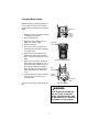
OL90150
OPERATOR’S MANUAL
WHEELBARROW
AIR
COMPRESSOR
!
WARNING:
To reduce the risk of injury, the user
must read and understand the
Operator’s Manual before using this
product.
IN614300AV 9/04
Printed in U.S.A.
Table of Contents
Section
Section
Page
Page
Table of Contents . . . . . . . . . . . . . . . .2
Installation . . . . . . . . . . . . . . . . . . . . .11
Safety Instructions . . . . . . . . . . . . . . .3
Getting to Know Your Air
Compressor . . . . . . . . . . . . . . . . . . .12
Safety Signal Words . . . . . . . . . . . . .3
Before Using the Air
Compressor . . . . . . . . . . . . . . . . . . . .3
Operating Your Air Compressor . . .14
Spraying Precautions . . . . . . . . . . . .5
Lubrication . . . . . . . . . . . . . . . . . . . .14
Breathable Air Warning . . . . . . . . . . .5
Operating Your Air Compressor . . .15
Warning Labels . . . . . . . . . . . . . . . . .6
For Trouble-Free Operation . . . . . .16
Motor Specifications and Electrical
Requirements . . . . . . . . . . . . . . . . . . .7
Maintenance . . . . . . . . . . . . . . . . . . .17
Moisture in Compressed Air . . . . . .14
Tank . . . . . . . . . . . . . . . . . . . . . . . . .18
Power Supply and Motor
Specifications . . . . . . . . . . . . . . . . . .7
Filter Removal, Inspection, and
Replacement . . . . . . . . . . . . . . . . . .18
General Electrical Connections . . . . .7
Drive Belt . . . . . . . . . . . . . . . . . . . . .18
110-120 Volt, 60 Hz Tool
Information . . . . . . . . . . . . . . . . . . . .8
Storage . . . . . . . . . . . . . . . . . . . . . .19
Extension Cords . . . . . . . . . . . . . . . .8
Maintenance Schedule . . . . . . . . . .19
Changing Motor Voltage . . . . . . . . . .9
Troubleshooting . . . . . . . . . . . . . . . .20
Thermal Overload Protector . . . . . .10
Repair Parts . . . . . . . . . . . . . . . . . . .24
Glossary of Terms . . . . . . . . . . . . . .10
Warranty . . . . . . . . . . . . . . . . . . . . . .28
Unpacking and Checking
Contents . . . . . . . . . . . . . . . . . . . . . .11
2
Safety Instructions
This manual contains information that is
very important to know and understand.
This information is provided for SAFETY
and to PREVENT EQUIPMENT PROBLEMS. To help recognize this information, observe the following symbols.
Warning indicates
a potentially hazardous situation which, if not avoided,
COULD result in death or serious injury.
Safety Signal Words
ardous situation which, if not avoided,
MAY result in minor or moderate injury.
!
Danger indicates
DANGER: an imminently haz-
!
WARNING:
!
CAUTION: potentially haz-
Caution indicates a
Notice indicates
important information, that if not followed, may cause damage to equipment.
NOTICE:
ardous situation which, if not avoided,
WILL result in death or serious injury.
Before Using the Air Compressor
4. Protect material lines and air lines
from damage or puncture. Keep hose
and power cable away from sharp
objects, chemical spills, oil, solvents,
and wet floors.
Since air compressors and other components (material pump, spray gun, filters,
lubrications, hoses, etc.) used make up a
high pressure pumping system, the following safety precautions should be
observed at all times. Only persons well
acquainted with these rules of safe operation should be allowed to use the air
compressor.
!
5. Never point a spray gun at oneself or
any other person. Accidental discharge may result in serious injury.
6. Check hoses for weak or worn condition before each use, making certain
all connections are secure; do not
use if deficiency is found. Notify an
authorized service facility for examination or repair.
WARNING:
All electrical work should be
done by a qualified (licensed or
certified) electrician. On a properly wired circuit, the black
wires supply a voltage potential
even when the unit is off.
7. Release all pressures within system
slowly; dust and debris may be harmful.
1. Read instruction manuals for each
component carefully, before attempting to assemble, disassemble or
operate your particular system.
!
WARNING:
Disconnect power and depressurize system before servicing
air compressor! (Turn pressure
regulator knob fully clockwise
after shutting off compressor.)
2. Wear safety glasses (meeting ANSI
Z87.1 or in Canada CSA Z94.3-99)
and use hearing protection when
operating the pump or unit. Everyday
glasses are not safety glasses.
3. Do not exceed pressure rating of any
component in system.
3
Safety Instructions (continued)
19. When spraying with solvent or toxic
chemicals, follow instructions provided by the chemical manufacturer.
8. Follow all local electrical and safety
codes, as well as the National
Electrical Code (NEC) and the
Occupational Safety and Health Act
(OSHA).
20. Spray in a well ventilated area, to
keep fumes from collecting and causing health and fire hazards.
9. Wiring and fuses should follow electrical codes, current capacity, and be
properly grounded.
21. Do not spray in vicinity of open
flames or other places where a spark
can cause ignition. Do not smoke
when spraying paint, insecticides, or
other flammable substances.
10. Electric motors must be securely and
adequately grounded. See grounding
instructions and extension cord information in this manual.
22. Use a respirator when spraying.
11. Always disconnect power source
before working on or near a motor, or
its connected load. If power disconnect point is out-of-sight, lock it in the
open position and tag to prevent
unexpected application of power.
23. NEVER reset safety valve or pressure switch. Keep safety valve free
from paint and other accumulations.
This provides safety against over
pressure.
12. Guard all moving parts; keep visitors
away. Never allow children in work
area.
24. Do regular maintenance; keep all
nuts, bolts, and screws tight, to be
sure equipment is in safe working
condition .
13. Use only a properly grounded outlet
that will accept a three pronged plug,
and wear shoes to prevent shock
hazards.
25. Keep cleaning rags and other flammable waste materials in a tightly
closed metal container and dispose of
later in the proper fashion.
14. Be careful when touching exterior of
operating motor; it may be hot
enough to cause injury.
26. Drain tanks of moisture after each
day’s use. If unit will not be used for a
while, it is best to leave drain cock
open until such time as it is to be
used. This will allow moisture to completely drain out and help prevent
corrosion of inside of tank.
15. Protect power cable from coming in
contact with sharp objects.
16. Clean electrical or electronic equipment with an approved cleaning
agent, such as dry, nonflammable
cleaning solvent.
27. Inspect tank yearly for rust, pin holes
or any other imperfections that could
cause it to become unsafe. NEVER
weld or drill holes in air tank.
17. To avoid spontaneous combustion,
discard waste rags into approved
metal waste cans.
28. Do not wear loose clothing or jewelry
that will get caught in the moving
parts of the unit.
18. Never store flammable liquids or
gases in vicinity of compressor.
4
Spraying Precautions
!
3. Do not direct paint or other sprayed
material at the compressor. Locate
compressor as far away from the
spraying area as possible to minimize
overspray accumulation on the compressor.
WARNING:
Do not spray flammable materials in vicinity of open flame or
near ignition sources including
the compressor unit.
4. When spraying or cleaning with solvents or toxic chemicals, follow the
instructions provided by the chemical
manufacturer.
1. Do not smoke when spraying paint,
insecticides, or other flammable substances.
2. Use a face mask/respirator when spraying and
spray in a well ventilated
area to prevent health and
fire hazards.
!
DANGER:
Breathable Air Warning
This compressor/pump is not equipped and should not be used “as
is” to supply breathing quality air. For any application of air for
human consumption, the air compressor/pump will need to be fitted
with suitable in-line safety and alarm equipment. This additional
equipment is necessary to properly filter and purify the air to meet
minimal specifications for Grade D breathing as described in
Compressed Gas Association Commodity Specification G 7.1 - 1966,
OSHA 29 CFR 1910. 134, and/or Canadian Standards Associations
(CSA).
DISCLAIMER OF WARRANTIES
In the event the compressor is used for the purpose of breathing air
application and proper in-line safety and alarm equipment is not
simultaneously used, existing warranties shall be voided, and
Campbell Hausfeld disclaims any liability whatsoever for any loss,
personal injury or damage.
5
Safety Instructions (continued)
Warning Labels
Find and read all warning labels found on
the air compressor shown below
DK724100AV 1000
6
Motor Specifications and
Electrical Requirements
Power Supply and Motor Specifications
!
The A-C motor used on this compressor
is a capacitor start, capacitor run nonreversible induction type, having the following specifications. It is wired at the
factory for operation on 110V-120V AC,
60 Hz service.
WARNING:
To reduce the risk of electrical
hazards, fire hazards or damage
to the tool, use proper circuit
protection. Your tool is wired at
the factory for operation using
the voltage shown. Connect
tool to a power line with the
appropriate voltage and a 15amp branch circuit. Use a 15amp time delay type fuse or circuit breaker. To reduce the risk
of shock or fire, if power cord is
worn or cut, or damaged in any
way, have it replaced immediately.
Voltage
Amperes
Hertz (Cycles)
Phase
RPM
110-120
15.0
220-240
7.5
60
Single
3450
General Electrical Connections
!
DANGER:
!
WARNING:
Do not permit fingers to touch
the terminals of plug when
installing or removing the plug
to or from the outlet.
To reduce the risk of electrocution:
1. Use only identical replacement parts when servicing.
Servicing should be performed by a qualified technician.
2. Do not use in rain or where
floor is wet. This tool is
intended for indoor residential use only.
7
Motor Specifications and
Electrical Requirements (continued)
110-120 volt, 60Hz Tool Information
If the grounding instructions are not completely understood, or if you are in doubt
as to whether the tool is properly grounded check with a qualified electrician or
service personnel.
The plug supplied on your tool may not
fit into the outlet you are planning to use.
Your local electrical code may require
slightly different power cord plug connections. If these differences exist refer to
and make the proper adjustments per
you local code before your tool is
plugged in and turned on.
!
In the event of a malfunction or breakdown, grounding provides a path of least
resistance for electrical current to reduce
the risk of electric shock. This tool is
equipped with an electric cord having an
equipment-grounding conductor and a
grounding plug, as shown. The plug must
be plugged into a matching outlet that is
properly installed and grounded in accordance with all local codes and ordinances.
WARNING:
If not properly grounded, this
tool can cause an electrical
shock, particularly when used
in damp locations, in proximity
of plumbing, or out of doors.
3-Prong Plug
Do not modify the plug provided. If it will
not fit the outlet, have the proper outlet
installed by a qualified electrician.
Properly
Grounded
3-Prong
Outlet
Improper connection of the equipmentgrounding conductor can result in a risk
of electric shock. The conductor with
insulation having an outer surface that is
green with or without yellow stripes is the
equipment-grounding conductor. If repair
or replacement of the electric cord or
plug is necessary, do not connect the
equipment-grounding conductor to a live
terminal.
TEST
RESET
Grounding Prong
Extension Cords
2. To avoid loss of power and overheating, additional air hose must be used
to reach work area instead of extension cords.
1. The air compressor should be located
where it can be directly plugged into
an outlet. An extension cord should
not be used with this unit.
8
Changing Motor Voltage
NOTE: The motor is prewired at the factory for 120V operation. Use the following procedure to change motor voltage to
240V.
Hitch pin
Motor
voltage
selector
switch
1. Unplug the power cord before making
or modifying connections.
2. Remove the hitch pin.
3. Toggle the motor voltage selector
switch from 120V to 240V.
Retaining
screw
4. Install the hitch pin.
5. Unscrew the pressure switch cover
retaining screw and remove the pressure switch cover.
6. Remove the black and white wires
labeled ‘line’ and the green ground
wire. Loosen the screw for the strain
relief.
Pressure Switch Cover
7. Install a 3 wire, 240 volt, 15 amp U.L.
listed cord (not provided). Be sure to
connect the white and black wires to
the terminals labeled ‘line’ and the
green ground wire to the ground terminal. Also tighten the strain relief
screw.
Line
terminals
8. Install the pressure switch cover and
fasten the pressure switch cover
retaining screw.
Ground
terminal
Strain relief
screw
Pressure Switch
The unit is now ready for 240 Volt operation.
!
WARNING:
If not properly grounded, this
tool can cause an electrical
shock, particularly when used
in damp locations, in proximity
of plumbing, or out of doors.
9
Motor Specifications and
Electrical Requirements (continued)
Thermal Overload Protector
!
CAUTION:
This compressor is equipped
with an automatic reset thermal
overload protector which will
shut off motor if it becomes
overheated.
4. Lack of proper ventilation.
5. Unit is being used with an extension
cord.
See Troubleshooting Chart for corrective
action.
!
CAUTION:
The motor must be allowed to
cool down before start-up is
possible. The motor will automatically restart without warning if left plugged into electrical
outlet, and the motor is turned
on.
If thermal overload protector shuts motor
OFF frequently look for the following
causes.
1. Low voltage.
2. Wrong gauge wire.
3. Clogged air filter.
Glossary of Terms
Air Tank Capacity
The volume of air stored in the tank and
available for immediate use. A large tank
allows the intermittent use of an air tool
with an air requirement higher than the
compressor’s rated delivery.
ASME Safety Valve
A safety valve that automatically releases
the air if the air receiver (tank) pressure
exceeds the preset maximum.
PSI (Pounds per Square Inch)
Measurement of the pressure exerted by
the force of the air. The actual psi output
is measured by a pressure gauge on the
compressor.
Volts or Voltage
A measurement of the force of an electrical current.
Amps or Amperage
A measure of the electrical force minus
the resistance on an electrical line.
RIDGID air compressors require 15
amps for operation. Be sure the compressor will operate on an electrical line
with the proper amps. If other appliances
operate on the same line, they will
reduce the available amps. If the amperage is not adequate, the result will be
blown fuses or tripped circuits.
SCFM (Standard Cubic Feet per
Minute)
Sometimes called CFM (Cubic Feet per
Minute). Measurement of air volume
delivered by the compressor.
Air Delivery
A combination of psi and SCFM. The air
delivery required by a tool is stated as
(number) SCFM at (number) psi. The
combination of these figures determines
what size unit is needed.
10
Glossary of Terms (continued)
Line Pressure Gauge
Displays the current line pressures. It is
regulated by the regulator knob.
Regulator
A control that adjusts the line pressure to
the proper amount needed to operate
spray guns and air tools.
Cut-in/Cut-off Pressure
Specific psi at which a compressor starts
and stops while refilling the air tank.
Tank Pressure Gauge
Indicates tank pressure in psi.
Unpacking and Checking Contents
1. Remove the air compressor from the
carton.
!
2. Place the compressor on a secure,
stationary work surface and look it
over carefully.
!
WARNING:
For your own safety, never
operate unit until all assembly
steps are complete and until
you have read and understood
the entire operator’s manual.
WARNING:
Do not operate unit if damaged
during shipping, handling or
use. Damage may result in
bursting and cause injury or
property damage.
!
WARNING:
To reduce the risk of injury, if
any parts are missing, do not
attempt to operate the air compressor until the missing parts
are obtained and installed correctly.
NOTICE:
THIS UNIT CONTAINS NO OIL!
Follow lubrication instructions
before operating compressor.
Installation
1. Check and tighten all bolts, fittings,
etc., before operating compressor.
4. To avoid loss of power and overheating, additional air hose must be used
to reach work area instead of extension cords.
2. Operate compressor in a ventilated
area so that compressor may be
properly cooled.
3. Compressor should be located where
it can be directly plugged into an outlet. An extension cord should not be
used with this unit.
11
Getting to Know Your Air Compressor
1
8
Belt Guard
Motor Voltage
Selector Switch
2
3
7
Air Storage
Tank
6
On/Off Switch
(Pressure
Switch)
5
Tank Drain
Valve
10
9
Regulated
Outlet Gauge
Air Filter
Dipstick
4
Handles
Regulator Knob
11
Tank
Pressure
Gauge
12
ASME
Safety Valve
13
Air Outlet Fittings
12
9. Regulated Outlet Gauge. This gauge
shows at-a-glance, air pressure at
outlet. Air pressure is measured in
pounds per square inch (PSI). Most
tools have maximum pressure ratings.
Never exceed the maximum pressure
rating of the tool you are using. Be
sure this gauge reads ZERO before
changing air tools or disconnecting
hose from outlet.
1. Belt Guard. The belt guard encloses
the pulleys and drive belt. It protects
the user from moving parts and
directs cooling air to the compressor
pump.
2. Air Filter. The air filter keeps dirt and
debris from entering the compressor
pump and reduces compressor noise.
3. Dipstick. The dipstick measures the
oil level in the compressor pump.
10.Regulator Knob. This knob controls
air pressure to an air operated tool or
paint spray gun. Turning the knob
clockwise increases air pressure at
the outlet. Turning counterclockwise
will lower air pressure at the outlet.
Fully counterclockwise will shut off the
flow of air completely.
Dipstick
Add Oil
Max
Low
Fill
Line
Close
Open
4. Handles. Used to move the compressor.
5. Tank Drain Valve. The tank drain
valve allows moisture to be removed
from the tank.
NOTE: Each tank has its own tank
drain valve.
11.Tank Pressure Gauge. Gauge shows
pressure in air storage tanks indicating compressor is building pressure
properly.
6. On/Off Switch. This switch allows for
manual control of the compressor.
Note that when the switch is turned
on, the compressor will automatically
start and stop depending on tank
pressure.
12.ASME Safety Valve. This valve automatically releases air if the tank pressure exceeds the preset maximum.
13.Air Outlet Fittings. These fittings are
1/4” universal-style quick connect fittings and allow rapid tool changes.
7. Air Storage Tanks. The tanks store
air for later use.
8. Motor Voltage Selector Switch.
Allows convenient voltage change
from 120 volts to 240 volts.
13
Operating Your Air Compressor
All lubricated compressor pumps discharge some condensed water and oil
with the compressed air. Install appropri-
ate water/oil removal equipment and controls as necessary for the intended application.
Moisture in Compressed Air
IMPORTANT: This condensation will
cause water spots in a paint job, especially when spraying other than water
based paints. If sandblasting, it will
cause the sand to cake and clog the gun,
rendering it ineffective.
A filter in the air line, located as near to
the gun as possible, will help eliminate
this moisture.
Moisture in compressed air will form into
droplets as it comes from an air compressor pump. When humidity is high or
when a compressor is in continuous use
for an extended period of time, this moisture will collect in the tank. When using a
paint spray or sandblast gun, this water
will be carried from the tank through the
hose, and out of the gun as droplets
mixed with the spray material.
Lubrication
Dipstick
NOTICE:
Add Oil
THIS UNIT CONTAINS NO OIL!
Follow lubrication instructions
before operating compressor.
Max
Low
Remove the dipstick and fill pump with 12
ounces of oil. Use single viscosity, ISO
100 (SAE 30), non-detergent compressor
oil; or Mobil 1® 5W30 or 10W30 synthetic oil
may also be used. See illustration for proper oil fill.
14
Fill
Line
Operating Your Air Compressor
1. Remove the dipstick and fill pump to the
proper oil level. See Lubrication Section.
8. After use, turn pressure switch knob
to the OFF position.
2. Open tank drain valves and turn regulator knob counterclockwise.
9. If compressor is not used for a long
period of time, bleed air from line and
use drain valve to drain water from
the valves and tank. Afterwards, follow the proper schedule of maintenance.
3. Turn pressure switch knob to OFF
position and plug in power cord.
4. Follow this step only if using your
compressor for the first time. Turn
pressure switch knob to AUTO position and run unit for 30 minutes to
“break in” the pump parts.
5. Close tank drain valves and turn regulator knob fully clockwise. Compressor
will build to maximum preset pressure
and shut off.
6. Turn regulator knob counterclockwise
to cause air to bleed off. Do not proceed to the next step until outlet pressure gauge reaches zero (0).
NOTE: This unit is equipped with a pressure switch that automatically turns the
motor OFF when the tank pressure
reaches a preset level. After air pressure
in the tank drops to a certain level, the
pressure switch automatically turns the
motor back on.
!
WARNING:
Do not over-pressurize any air
tool. Consult air tool instructions for proper air tool pressure.
7. Attach hose. Add chuck or other tool
to open end of hose. Turn regulator
knob clockwise until desired outlet
pressure is reached.
15
Operating Your Air Compressor (continued)
For Trouble-Free Operation
sure to close tank drain valves before
operating compressor.
1. Read instructions: Carefully read
through this operator’s manual
BEFORE OPERATING the new air
compressor. It contains information
about operation and maintenance of
the unit.
3. Change air filter: Never run compressor without an air filter nor with a
clogged air filter. Replace with a new
filter when the element is dirty.
2. Drain tanks daily: Depressurize system prior to draining tanks. Open tank
drain valves and drain moisture from
tanks. This helps prevent tank corrosion and keeps oil and moisture out
of the compressed air system. Be
16
Maintenance
!
WARNING:
Release all pressure and disconnect power before making
any repair.
1. Check compressor for any visible
problems, especially check air filter to
be sure it is clean.
2. Pull ring on safety valve and allow it to
snap back to normal position.
!
4. Turn power OFF and clean dust and
dirt from motor, tank, air lines and
pump cooling fins.
WARNING:
NOTE: The air filter in the filter housing
on the side of the head must be checked
and cleaned periodically, more often if
used under very dusty conditions or
when a great deal of fog from spraying is
allowed to circulate near unit.
Safety valve must be replaced if
it cannot be actuated or it leaks
air after ring is released.
IMPORTANT: Unit should be located as
far from spraying area as hose will allow
to prevent over-spray from clogging filter.
3. Drain moisture from tanks daily. Shut
compressor off. Depressurize system
prior to draining tanks. Drain moisture
from tanks by opening the tank drain
valves underneath the tanks.
17
Maintenance (continued)
Tank
!
DANGER:
Never attempt to repair or modify a tank! Welding, drilling or
any other modification will
weaken the tank resulting in
damage from rupture or explosion. Always replace worn,
cracked or damaged tanks.
Tank Drain (2)
NOTICE:
Drain liquid from tanks daily.
The tanks should be carefully inspected
at a minimum of once a year. Look for
cracks forming near the welds. If a crack
is detected, remove pressure from tank
immediately and replace.
TO OPEN
Filter Removal, Inspection and Replacement
To change a filter, pull off the filter housing
cover. If filter element is dirty, replace element or entire filter.
Drive Belt
Belt stretch is a result of normal use.
When properly adjusted, the belt deflects
about 1/2” with five pounds of pressure
applied midway between the motor pulley
and pump.
To adjust drive belt tension:
1. Before servicing, put on ANSI Z87.1approved eye protection. Turn off and
unplug compressor. Drain all moisture
and air from unit by fully opening tank
drain valve.
18
1/2” Deflection
2. With a marker, mark the edge where
the motor meets the base (the edge
farthest away from the pump).
3. Remove the belt guard bolt and nut.
4. Remove the front belt guard cover.
5. Loosen the four motor mounting
bolts.
6. The belt tension will pull the motor
toward the pump. Remove the belt
from the unit and set it on the ground.
7. Using the reference mark made in
step 1, move the motor approximately
1/4" past the mark (moving it away
from the pump).
8. Use a straight edge to make sure the
motor pulley is in line with the pump
flywheel. Tighten down the two motor
bolts furthest from the pump.
9. Put the belt on the motor pulley and
carefully roll it over the pump flywheel. Do this by starting the other
end of the belt over the top of the
pump flywheel and turning the flywheel counterclockwise.
Touch Rim in Two
Places
!
Straight Edge
Parallel With Belt
CAUTION:
When installing belt, use
caution to avoid injury to
fingers or hands.
10. Check belt tension. If still too loose,
loosen the front two motor bolts and
repeat steps 4-6. (When doing so,
move motor an additional 1/4" away
from pump).
11. When belt tension is good, tighten the
other two motor bolts.
12. Install the front belt guard cover.
13. Install and tighten the belt guard bolt
and nut.
Storage
1. When not in use, compressor should be 3. Hose should be disconnected and hung
stored in a cool dry place.
open ends down to allow any moisture
to drain.
2. Tanks should be drained of moisture.
Maintenance Schedule
Operation
Daily
Weekly
Drain Tanks
Check Air Filter
Check Safety Valve
Blow Dirt From Inside Motor
19
Troubleshooting
!
WARNING:
For your own safety do not try
and run the air compressor
while troubleshooting.
TROUBLE
Compressor will not
run
PROBABLE CAUSE
1. Unit is plugged into
extension cord
2. No electrical power
3. Blown fuse
4. Breaker open
5. Thermal overload open
6. Pressure switch bad
Motor hums but cannot run or runs slowly
Fuses blow/circuit
breaker trips repeatedly
REMEDY
1. Remove extension cord
2. Verify unit is plugged in.
Check fuse/breaker or
motor overload
3. Replace blown fuse
4. Reset, determining why
problem happened
5. Motor will restart when cool
6. Replace
1. Low voltage
2. Unit is plugged into
extension cord
3. Shorted or open motor
winding
4. Defective check valve or
unloader
1. Check with voltmeter
2. Remove extension cord
1. Incorrect size fuse, circuit
overloaded
1. Check for proper fuse, use
time-delay fuse.
Disconnect other electrical
appliances from circuit or
operate compressor on its
own branch circuit
2. Remove extension cord
2. Unit is plugged into
extension cord
3. Defective check valve or
unloader
20
3. Replace motor
4. Replace or repair
3. Replace or repair
TROUBLE
Thermal overload
protector cuts out
repeatedly
PROBABLE CAUSE
1. Low voltage
2. Clogged air filter
3. Lack of proper ventilation/room temperature
too high
4. Unit is plugged into
extension cord
Air tank pressure
drops when compressor shuts off
1. Loose connections (fittings, tubing, etc.)
2. Tank drain valve open
3. Check valve leaking
REMEDY
1. Check with voltmeter
2. Clean filter (see
Maintenance section)
3. Move compressor to well
ventilated area
4. Remove extension cord
1. Check all connections with
soap and water solution
and tighten
2. Close valve
3. Disassemble check valve
assembly, clean or replace
!
DANGER:
Do not disassemble
check valve with air in
tank; bleed tank
1. Excessive water in air
tanks
2. High humidity
1. Drain tanks
1. Defective pressure
switch
2. Excessive air usage
1. Replace switch
Compressor vibrates
Loose mounting bolts
Tighten
Air output lower than
normal
1. Broken inlet valves
1. Have authorized service
representative repair unit
2. Clean or replace intake filter
3. Tighten connections
Excessive moisture
in discharge air
Compressor runs
continuously
2. Intake filter dirty
3. Connections leaking
21
2. Move to area of less
humidity; use air line filter
2. Decrease air usage; compressor not large enough
for a requirement
Troubleshooting (continued)
TROUBLE
Low discharge pressure
PROBABLE CAUSE
1. Air leaks
2. Leaking valves
REMEDY
1. Listen for escaping air.
Apply soap solution to all
fittings and connections.
Bubbles will appear at
points of leakage. Tighten
or replace leaking fittings
or connections
2. Remove head and inspect
for valve breakage, weak
valves, scored valve seats,
etc. Replace defective
parts and reassemble
!
3. Restricted air intake
4. Slipping belts
5. Blown gaskets
6. Low compression
22
CAUTION:
Be sure that the old head
gasket is replaced with a
new one each time the
head is removed
3. Clean the air filter element
4. Adjust tension (See Drive
Belt Section)
5. Replace any gaskets
proven faulty on inspection
6. Low pressure can be due
to worn rings and cylinder
walls. Correction is made
by replacing the rings,
cylinders, and pistons as
required
TROUBLE
Excessive belt wear
PROBABLE CAUSE
1. Pulley out of alignment
2. Belt too loose or too tight
3. Belt slipping
4. Pulley wobbles
Oil in the discharge
air
1. Worn piston rings
2. Compressor air intake
restricted
REMEDY
1. Realign motor pulley with
compressor pulley
2. Adjust tension (See Drive
Belt Section)
3. Adjust tension or replace
belt (See Drive Belt
Section)
4. Check for worn crankshaft,
keyway or pulley bore
resulting from running the
compressor or motor with
loose pulleys. Check for
bent pulleys or bent crankshaft
1. Replace with new rings
2. Clean filter. Check for other
restrictions in the intake
system
3. Restricted breather
3. Clean and check breather
for free operation
4. Excessive oil in compres- 4. Drain down to full level
sor
5. Wrong oil viscosity
5. Use SAE 30 (ISO 100)
non-detergent compressor
oil, Mobil 1 5W30 or Mobil
1 10W30 (See page 14).
6. Connecting rod out of
6. Replace rod
alignment
23
Repair Parts
24
27
37
26
35
25
31
28
29
32 30
33
17
19 18
16
11
34
15
To pump
10
13
21
43
7
6
12
39
22
14
20
42
40
1
41
3
2
4
5
24
23
8
9
Repair Parts
For Repair Parts, Call 1-800-4-RIDGID
Please provide following information:
-Model number
-Serial number (if any)
-Part description and number as shown in parts list
Ref.
No.
1
2
3
4
5
6
7
8
9
10
11
12
13
14
15
16
17
18
19
20
21
22
23
24
25
26
27
28
29
30
31
32
33
34
35
36
37
38
39
40
41
42
43
Catalog
Number
20353
17853
18038
20358
20363
20368
20373
20378
20383
17883
17888
17868
17898
17798
20388
20393
17753
20398
17908
17878
17793
17773
17873
20403
17998
18088
18093
20408
18078
20413
20418
20423
18113
20428
20433
20438
20443
20448
18053
18043
18048
20453
20458
Part
Number
AR054700CG
ST158300AV
ST116400AV
ST085800AV
ST160000AV
CV221515AV
ST186601AV
ST081301AV
ST117802AV
CW210000AV
ST022500AV
ST119704AV
HF002401AV
V-215106AV
EC012602AV
CW209500AV
ST209800AV
EC012800AV
CW211300AJ
GA016900AV
WL024501AV
GA016901AV
HF203300AV
BG220200AJ
ST026200AV
KE000900AV
ST012200AV
PU015200AV
PU015900AV
BT020400AV
KE000903AV
ST016000AV
ST011200AV
ST146001AV
MC018300IP
ST073249AV
VT480000KB
ST085700AV
WA005501AV
AA021800AV
ST073613AV
ST073611AV
ST071626AV
Description
Tank
Rubber Foot
Screw
Drain Valve
Handle Grip
Check Valve
Exhaust Tube
Push-In Fitting
Unloader Tube
Unloader
1/4” Plug
Elbow
Nipple
Safety Valve
Power Cord
Strain Relief
Strain Relief Screw
Motor Cord
Pressure Switch
Outlet Gauge
Regulator
Tank Gauge
Coupler
Belt Guard Assembly
3/8" Set Screw
3/16" Key
1/4" Set Screw
Pulley
Flywheel
Belt
Key
Motor Bolt
5/16" Washer
5/16" Nut
Electric Motor
Tapping Screw
Pump
Filter
Wheel
Axle Rod
Plug
Plug
Screw, Torx 1/4 - 20 x 1/2”
25
Qty
1
4
4
2
2
1
1
1
1
1
2
2
1
1
1
1
1
1
1
1
1
1
2
1
1
1
1
1
1
1
1
4
4
4
1
4
1
1
1
1
2
2
4
Repair Parts
22
16
21
25
15
23
24
23
14
5
6
7
13
4
26
3
11 10
2
19
18
12
9
20
8
1
17
26
Repair Parts
For Repair Parts, Call 1-800-4-RIDGID
Please provide following information:
-Model number
-Serial number (if any)
-Part description and number as shown in parts list
Ref.
No.
Catalog
Number
Part
Number
Description
1
2
3
4
18143
—
18133
18128
VT040300AG
VT041700AJ
VT040750AG
Crankcase
Crankcase gasket
Dipstick breather
Cylinder
5
6
7
8
9
10
11
12
13
14
15
16
17
18
19
20
21
22
23
24
25
26
—
18158
18163
18148
18153
—
18178
18173
18183
18188
—
18193
18138
18078
17998
18088
20448
20488
—
—
—
18168
18198
18203
18208
VT040100AG
VS001400AV
ST084202AV
VT040600AJ
ST129700AV, VT040200AJ
ST076840AV
VT470800AJ
TQ900800AJ
ST022300AV
PU015900AV
ST026200AV
KE000900AV
ST085700AV
ST085701AV
TQ011900AG, REPAIR
VT470900AJ
VT210400AJ
VT005501AJ
27
Cylinder gasket
Connecting rod
Piston pin
Ball bearing
Crankshaft Assembly
O-ring
Oil seal
Bearing cap assembly
M6-1.00 x 10 cap screw
Valve plate assembly
Valve plate gasket
Cylinder head & fasteners
1/8” NPT oil drain plug
Flywheel
3/8-16 x 3/4” Setscrew
3/16” key
Air filter
Filter element
Oil ring
Expander
Ring
Piston
KITS
Gasket kit
Piston ring set
Piston service kit
Qty
1
1
1
1
1
2
2
2
1
1
1
1
4
1
1
1
1
1
1
1
1
1
4
2
4
2
1
1
2
RIDGID AIR COMPRESSOR LIMITED THREE YEAR WARRANTY
This product is manufactured by Campbell Hausfeld. The trademark is licensed from
RIDGID, Inc. All warranty communications should be directed to RIDGID air compressor technical service at (toll free) 1-800-4-RIDGID.
WHAT IS COVERED UNDER THE LIMITED THREE YEAR WARRANTY
This warranty covers all defects in workmanship or materials in this RIDGID air compressor for the three-year period from the date of purchase. This warranty is specific to this air compressor. Warranties for other RIDGID products may vary.
Catalog No. OL90150
Model No. OL90150
Serial No. ___________
The model and serial numbers may be found on your
unit. You should record both model and serial number
in a safe place for future use.
HOW TO OBTAIN SERVICE
To obtain service for this RIDGID air compressor you must return it, freight prepaid,
to a service center authorized to repair RIDGID air compressors. You may obtain the
location of the service center nearest you by calling (toll free) 1-800-4-RIDGID or by
logging on to the RIDGID website at www.ridgid.com. When requesting warranty
service, you must present the proof of purchase documentation, which includes a
date of purchase. The authorized service center will repair any faulty workmanship,
and either repair or replace any defective part, at Campbell Hausfeld’s option at no
charge to you.
WHAT IS NOT COVERED
This warranty applies only to the original purchaser at retail and may not be transferred. This warranty does not cover normal wear and tear or any malfunction, failure or defect resulting from misuse, abuse, neglect, alteration, modification or repair
by other than a service center authorized to repair RIDGID branded air compressors.
Expendable materials, such as oil, filters, etc. are not covered by this warranty.
Gasoline engines and components are expressly excluded from coverage and you
must comply with the warranty given by the engine manufacturer, which is supplied
with the product. CAMPBELL HAUSFELD MAKES NO WARRANTIES,
REPRESENTATIONS OR PROMISES AS TO THE QUALITY OR PERFORMANCE OF ITS AIR COMPRESSORS OTHER THAN THOSE
SPECIFICALLY STATED IN THIS WARRANTY. RIDGID, INC. MAKES NO
WARRANTIES OR REPRESENTATIONS, EXPRESS OR IMPLIED,
INCLUDING AS NOTED BELOW.
ADDITIONAL LIMITATIONS
To the extent permitted by applicable law, all implied warranties, including warranties
of MERCHANTABILITY or FITNESS FOR A PARTICULAR PURPOSE, are disclaimed.
Any implied warranties, including warranties of merchantability or fitness for a particular purpose, that cannot be disclaimed under state law are limited to three years
from the date of purchase. Campbell Hausfeld is not responsible for direct, indirect,
incidental, special or consequential damages. Some states do not allow limitations
on how long an implied warranty lasts and/or do not allow the exclusion or limitation
of incidental or consequential damages, so the above limitations may not apply to
you. This warranty gives you specific legal rights, and you may also have other
rights, which vary from state to state.
QUESTIONS OR COMMENTS
CALL 1-800-4-RIDGID
www.ridgid.com
Please have your Model Number and Serial Number on hand when calling.
© 2004 RIDGID, INC.
Part No. IN614300AV 9/04
Form No. IN614300AV
Printed in U.S.A. 9/04