1
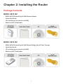
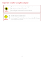
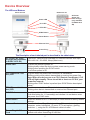
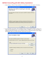
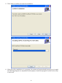
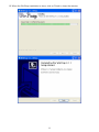
BiPAC 2073 R2
HomePlug AV 200 Ethernet Adapter
BiPAC 2074 R2
HomePlug AV 200 Ethernet Bridge with
AC Pass-Through
User Manual
Firmware Version 4.0.1
Last revised on Mar 2010
Safety Warnings
1. Do not use the adapter in high humidity or high temperature environment.
2. Do not open or repair the case yourself.
3. Avoid using this product and all its accesories outdoor.
4. Place the adapter on a stable surface.
5. Only “HomePlug AV” compliant Powerline Communication (PLC) adapter for remote access is
necessary.
6. Plug your BiPAC HomePlug AV device directly to the AC outlet on the wall. It is best to avoid
using extension power cable as it may possess noise filter or surge protector functions that may
cause interference that may impact the performance of the device.
7. Use only IT products (eg. fax machine, router) that are below 6Amp for the built-in AC outlet of
BiPAC 2074 R2.
Table of Contents
Chapter 1: Product............................................................................. 1
Introduction.................................................................................. 1
Features....................................................................................... 2
Chapter 2: Installing the Router........................................................ 3
Package Contents........................................................................ 3
BiPAC 2073 R2....................................................................................3
BiPAC 2074 R2....................................................................................3
Important note for using this adapter..........................................................4
Device Overview.........................................................................................5
Hardware Installation (For separated plug clip type only)...........................7
Connecting the HomePlug Adapter.............................................................9
Power Connection................................................................................9
LAN Connection.................................................................................10
AC Pass-Through Connection........................................................... 11
Networking Setup...............................................................................12
Setup Utility........................................................................................13
Quick Start (Setup Powerline Network)...................................... 14
Push Button usage.............................................................................14
Application Scenarios........................................................................14
Powerline Network Illustration............................................................16
Chapter 3: Installation...................................................................... 17
Utility Installation........................................................................ 17
BiPAC HomePlug AV 200 Utility Installation............................... 18
Chapter 4: Configuration................................................................. 24
Accessing BiPAC HomePlug AV 200 Utility................................ 24
BiPAC HomePlug AV Utility........................................................ 25
Main Tab............................................................................................25
Privacy Tab........................................................................................29
QoS Tab.............................................................................................30
Diagnostic Tab...................................................................................32
Firmware Download Tab....................................................................34
About Tab...........................................................................................35
Firmware Upgrade.............................................................................36
Chapter 5: Troubleshooting............................................................. 39
Appendix: Product Support & Contact........................................... 40
Chapter 1: Product
Introduction
BiPAC HomePlug AV 200 is a networking device that utilizes the existing wiring system as a path
to transmit data signal through the inter-conversion between digital and analog signal. With this
functionality, HomePlug AV devices can be plugged into an AC outlet to draw power and at the
same time establishing a network connection between two or more Ethernet devices.
BiPAC HomePlug AV 200 can be used to bridge any Ethernet device to your Powerline network
in your home or office. With this technology, Ethernet devices in your home or office can equally
share high speed data transmission rate without the need to spend excessive time and money
installing expensive Ethernet cable. It can be plugged into an Ethernet port on a router to equip
a network with powerline capabilities and take advantage of the router features. HomePlug AV
device can also be plugged directly into a cable or DSL modem that allows instant internet access
over home Powerlines to each computer equipped with a HomePlug AV certified Powerline
network adapter. BiPAC HomePlug AV 200 makes high-speed modem sharing as fast and simple
as plugging the devices in the wall.
1
Features
1. Physical layer data rate up to 200Mbps over existing Powerline.
2. Uses powerline technology that takes advantage of the unused bandwidth of the electrical wiring in the home.
3. Ideal for Triple Play applications such as IPTV, VoIP telephony and high-speed Internet access.
4. Support 10/100 (MDI/MDIX) Ethernet switching.
5. Compliant with the HomePlug Powerline Alliance Industry specification HomePlug AV.
6. Power supplier design inside.
7. Ideal for Residential Users.
8. Power Saving mode: When PC / other Ethenet devices are completely power off or when there
is no Ethernet cable connected, HomePlug device will automatically enter power saving mode
which will help to reduce power consumption.
9. Noise Filter (only available in BiPAC 2074 R2): Allow the filtering of noise which may be generated by some electrical appliances such as vacuum cleaner and hair dryer to prevent possible
interference with HomePlug AV network.
2
Chapter 2: Installing the Router
Package Contents
BiPAC 2073 R2
• BiPAC 2073 R2 HomePlug AV 200 Ethernet Adapter
• Quick Start Guide
• CD (containing user manual and QSG)
• Ethernet (CAT-5 LAN) cable
BiPAC 2074 R2
• BiPAC 2074 R2 HomePlug AV 200 Ethernet Bridge with AC Pass Through
• Quick Start Guide
• CD (containing user manual and QSG)
• Ethernet (CAT-5 LAN) cable
3
Important note for using this adapter
4
Device Overview
The LEDs and Buttons
BiPAC 2074 R2
BiPAC 2073 R2
Power LED
PLC LED
AC Power
Outlet / AC
Pass-through
(only available
in BiPAC 2074
R2)
ETH LED
SYNC Button
Reset Button
Ethernet Port
Power Plug
The Description of each labeled part is described in the table below.
AC Outlet / AC PassFiltered AC Pass-through available for electrical devices with Input:
through (only available 100~240V AC, 50~60Hz, 6Amp (Maximum).
in BiPAC 2074 R2)
Power LED
Lit when the device is power on.
Blinking briefly when the device enters power saving mode.
Blinking when pushing the SYNC button.
Lit off when power is off.
PLC (Powerline Link/
Act) LED
Lit green when the power line connection is established.
Blinking quickly when data is transmitted or received via power line.
Note: When the device acts as a CCO (Central Coordinator), PLC
LED will light steadily. There should be at least one CCO in your
powerline network.
Blinking after SYNC button is pushed (see SYNC Button descripted
below).
Lit when connected to an Ethernet device.
Blinking when data is transmitted or received via Ethernet port.
ETH (Ethernet Link/
Act) LED
SYNC Button
Reset Button
Ethernet Port
Used to establish a LAN network with other power line devices.
Push this button for 1~3 second(s) and release it to set device enter
the power line SYNC state.
Press this button to for 1~3 second(s) to reset device to factory default
settings.
Connect the HomePlug AV device with an Ethernet device (e.g.
computer, router, hub/switch , IP pone, IPTV set-top-box, gaming
consoles…), using the RJ-45 Ethernet cable included.
Power Plug / AC Power Plug into an AC outlet for power supply and to build a powerline
Cord
network with other HomePlug AV devices.
5
The Rear Side and Look
BiPAC 2073 R2
(For separated plug clip type only)
BiPAC 2074 R2
Clip Socket:
Install the clip
into this socket
6
Power Plug
Hardware Installation (For separated plug clip type
only)
Refer to the following diagrams and direction to install the clip with BiPAC 2073 R2:
Example 1: EU clip.
• Please check the lock instruction on your clip.
• If you got the “Triangle Lock”, refer to right diagram.
7
Example 2: UK clip.
• Please check the lock instruction on your clip.
• If you got the “Circle Lock”, refer to right diagram.
8
Connecting the HomePlug Adapter
It is easy to connect the device simply by performing the following instructions:
Power Connection
BiPAC 2073 R2
Plug the Homeplug AV 200 Ethernet Adapter into the wall outlet/socket.
BiPAC 2074 R2
Plug the embedded AC power cable to the wall outlet/socket.
Note: Plug/socket, power cable and input voltage/frequency may vary from country to
country.
9
LAN Connection
Connect the supplied RJ-45 Ethernet cable to the Ethernet port on HomePlug AV 200 Ethernet
bridge/adapter and the other side to the device’s Ethernet interface.
10
AC Pass-Through Connection
BiPAC 2074 R2 only
Plug IT electrical devices (e.g. ADSL router, Set-to-box, notebook, etc.) into the built-in AC passthrough with an embedded low-pass filter to prevent electrical noise from interfering on your
powering network.
11
Networking Setup
Refer to the following steps:
1. Connect a network cable to the adapter or bridge and then plug the device into a power
socket.
BiPAC 2074 R2
BiPAC 2073 R2
2. Then connect the device to a PC, modem, router or set-top-box.
BiPAC 2074 R2
BiPAC 2073 R2
3. Create a secure network by simply pushing the SYNC button for 1~3 seconds.Please refer to
Quick Start (Setup Powerline Network) section for more detail description.
BiPAC 2074 R2
BiPAC 2073 R2
12
Setup Utility
After you complete the hardware installation, insert the CD-ROM to the CD-ROM drive to perform
Setup Utility for network configuration. The Setup Utility will auto-run. Follow the step-by-step
configuration wizard, the utility will guide you complete the basic network configuration.
See Utility Installation section.
13
Quick Start (Setup Powerline Network)
Push Button Usage
SYNC Button is used to add a HomePlug device to a powerline network or remove it from current
pwoerline network. There are 2 types of SYNC Button trigger state:
1. Joining a Network: Press the SYNC button on the device for less than 3 seconds. Press the
SYNC button on another device connected to the same medium for less than 3 seconds.
Wait a few seconds for the two devices to form a network. A join operation can be cancelled
by pressing the SYNC button on the first device again, for less than 3 seconds, instead of
pressing the SYNC button on the second device.
2. Leaving a Network: Press the SYNC button on the device for more than 10 seconds. Wait
a few seconds for the device to reset and leave the network. The device is then free to join
another HomePlug AV logical network.
There are two role in Joining a Network. The "adder" is the device that gives a Network Name to
another device. The "joiner" is the device that takes a Network Name from another device. When
the two device have the same Network Name, they will form a HomePlugAV Logical Network.
The role of "adder" or "joiner" is determined automatically by each device when the SYNC button
is pressed. A device that belongs to an existing logical network will become an "adder". A device
that does not belong to a network will become a "joiner". Only one "adder" and one "joiner" can
participate in "Joining a Network" process at the same time. If both devices are "joiners", the
device with the higher MAC address becomes the "adder" by default.
Application Scenarios
Scenario 1: A BiPAC HomePlug AV device A wants to form a network group with another
BiPAC HomePlug AV device B
It doesn't matter which SYNC button of the device is pressed first. Because device A and B are left
from the original network, they are both "joiner" now. When "Joining a Network" process starts, the
devices will determine which one is "adder" and the other one is "joiner" automatically.
Example:
1. Press the SYNC button of device A for more than 10 seconds to make sure that it is detached
completely from any possible network group.
2. Press the SYNC button of device B for more than 10 seconds to make sure that it is detached
completely from any possible network group.
3. Press the SYNC button of device A for 1~3 seconds, you should find the Power LED blinks
steadily signifying it is in “Joining a Netrwork” process.
4. Press the SYNC button of device B for 1~3 seconds, you should find the Power LED blinks
steadily signifying it is in “Joining a Network” process.
5. Wait for the PLC LEDs of both devices lit steadily, you will now have these devices being in
the same network group.
14
Scenario 2: A BiPAC HomePlug AV device wants to join an existing network group BC
Device A wants to Joining a Network group "BC" currently consisting of device B and device C.
Any devices within the "BC" group can become the "adder" and device A will be the "joiner".
Example:
1. Press the SYNC Button of device A for more than 10 seconds to make sure that it is detached
completely from any possible network group.
2. Press the SYNC button of device B or C of the BC network group for 1~3 seconds to turn it
into “adder”, you should find the Power LED blinks steadily signifying it is in “Joining a Network” process.
3. Press the SYNC button of device A for 1~3 seconds to turn it into “joiner”, you should find the
Power LED blinks steadily signifying it is in “Joining a Network” process.
4. Wait for the PLC LEDs of both devices lit steadily, you will now have device A joined with the
network group BC.
Scenario 3: A BiPAC HomePlug AV device A of network group AD wants to join an existing
network group BC
For a device which already belongs to a network group is to join with a different network group,
that device has to be left from its current attached group first.
Example:
1. Press the SYNC Button of device A for more than 10 seconds to leave from network group
AD.
2. Then press the SYNC button of device (B or C) of network group BC for 1~3 seconds to turn it
to “adder”, you should find the Power LED blinks steadily signifying it is in “Joining a Network”
process.
3. Press the SYNC button of device A again for 1~3 seconds to turn it to “joiner”, you should find
the Power LED blinks steadily signifying it is in “Joining a Network” process.
4. Wait for the PLC LED of both devices A and (B or C) lit steadily. Now you will have device A
join the network group BC.
15
Powerline Network Illustration
16
Chapter 3: Installation
Utility Installation
The utility can be used on the following Windows platform: Windows 2000/XP/Vista/7.
1. Place the BiPAC HomePlug AV 200 Utility auto-installation CD into your CD-ROM/DVD-ROM
drive.
2. Click on Utility for Easy Installation to install the utility.
17
BiPAC HomePlug AV 200 Utility Installation
1. After clicking on Utility for Easy Installation, the installation wizard will appear. Click Next.
2. You may define the location of the installation folder using the Browse button, however it is
highly recommended that you use the default location. In addition, you can also choose to
install HomePlug AV 200 Utility only for yourself or for all the users who share your PC. When
all necessary items are properly selected, press Next to proceed.
18
3. Press Next to confirm and start the installation.
4. While the utility installlation is in progress, the system will automatically prompt you to install
the WinPcap program in a separate window pop-up. Install this program in order for the utility
to work well.
19
5. While the utility installlation is in progress, the system will automatically prompt you to install
the WinPcap program in a separate window pop-up. Install this program in order for the utility
to work well.
6. When the WinPcap installation window pops up, click Next to proceed with the installation.
7. Click on Next to proceed to the next step.
20
8. Read through the license agreement then click on I Agree button to accept the agreement
term.
9. If you want the WinPcap driver run automatically when booting, please tick Automatically start
the WinPcap driver at boot time. Then click on install to continue the installation.
21
10.When the WinPcap installation is done, click on Finish to close the window.
22
11.When the WinPcap installation is done, you will have also completed the BiPAC HomePlug
AV 200 Utility installation as well. You may now click on the close button of the Utility installation window to finish the process.
23
Chapter 4: Configuration
Accessing BiPAC HomePlug AV 200 Utility
Once the BiPAC HomePlug AV 200 Utility Setup Wizard is installed, a shortcut will appear on the
desktop. You can start the BiPAC HomePlug AV Utility by double clicking on the shortcut, or go
through “start”→ “All Programs”→ “BiPAC HomePlug AV Utility” →“BiPAC HomePlug AV Utility”.
24
BiPAC HomePlug AV Utility
Billion BiPAC HomePlug AV Utility consists of 6 screens accessed through 6 panel tabs. The 6
panels are Main, Privacy, Diagnostics, QoS, Firmware download and About located on the top left
corner of the program for configuration convenience.
Main Tab
The Main Tab screen lists all the powerline devices that are connected to the host computer when
the utility is running.
The top left window panel shows all the local HomePlug AV devices that are connected to the
computer’s NIC (Network Interface Card). Normally, only one device will be seen on the list. If
there is more than one local device being connected, user can select the local device by clicking
on it and then click the Connect button to its right to use it to connect to the internet. Once
connected to the local device, the utility will automatically scan the power line periodically for other
newly connected HomePlug AV devices. If no local HomePlug AV devices are discovered, the
status area above the connect button will indicate with a message "NO HOMEPLUG ADAPTERS
DETECTED".
The bottom window panel displays all the HomePlug remote devices that are detected on the
current network. The total number of remote devices connected on the same network can be
found on top of the Remote device panel. Within this panel, you can also find some useful
informations of each remote device such as its connection quality, transfer rate and MAC address.
25
The Network type (Public or Private) is also displayed based on the network status of the local
device. The scan status option is displayed on the top right corner above the Remote devices
panel showing whether the Autoscan function is turned ON or OFF.
The following information is displayed for all devices that appear in the lower panel:
Device Name:
Show the default device name. User can change the name by either clicking on the rename button
or by clicking on the name and editing in-place. An icon is usually shown with the device name.
Password (*required when one needs to change the Private Network Name of the devices)
This column is left blank by default. The password will be displayed only after it has been entered.
For detail information on password setup, please refer to section on Password Setup Instruction.
Each device comes with a unique password and it can be found at the back of the device itself.
Quality:
Display the overall quality of the data transmission rate. When the transmission rate is good, the
number of line appear will increase.
Rate (Mbps):
Display the data transmission rate of each device.
MAC Address:
Show the Remote device MAC address.
26
Password Setup Instructions:
This feature grants users the access level to change the Private Network Name of both the
local & the remote HomePlug AV devices. Password is required if one is to change the Private
Network Name of each devices within the powerline network in order for all devices to be able to
communicate & synchronize with each other within the network.
1. To enter a password for a specific device, select the device and click on the Enter Password
button at the bottom of the lower panel to call up the Set Device Password dialog box.
2. Then type in the password in the blank provided and press OK.
Note: The password of each HomePlug device can be found at the back of the device.
27
3. If the password entered is not recognized or unacceptable, an error message box will pop up
prompting user to change the password. Click OK then re-enter the password again.
4. If the password entered is correct, you will see that the password will be displayed next to
the device.
28
Privacy Tab
Privacy Tab allows user the convenience to manage the security of the private powerline network.
In addition, user can also uitlize this feature to add a new HomePlug device to the private network
instead of manually adding the device using its SYNC button. In order to add devices to the
network through the utility GUI, Private Network Name of each device is required to be the same
with the local device.
All HomePlug AV devices are shipped using a default logical network name “HomePlugAv”. The
Privacy tab screen allows user to change its default public network type to a private network by
changing the network name (network password) of the device.
The user can always reset the network type to HomePlug network (Public) by entering
“HomePlugAv” as the network name or by clicking on the Use Default button.
Note: Changing the network name to anything other than HomePlugAv will show the
network type on the main screen as Private.
Set Local Device Only button can be used to change the Private Network Name of the local
device. If a new Private Network Name is entered, all associated devices seen on the Main Tab
previously will no longer be present in the new network, thus causing the local device unable to
communicate with other devices which were in the network previously.
Set All Devices button is used to change the Private Network Name of all devices that appear
on the Main tab screen whose Device Password had been entered correctly. For devices whose
device passwords were not entered, this operation will fail and will report a failure message.
29
QoS Tab
This function allows user the flexibility to manage the bandwidth usage for each HomePlug device.
The higher the QoS priority the more bandwidth usage is allocated to that particular device.
30
To set the QoS priority of each device:
1. Click to select the type that you want to set the QoS priority.
2. In the Priority setting fields, click on Add/Modify button, then enter the IP address/MAC address and drag the Priority slider to either Low, Normal, Medium or High position. When the
position of the slider is set, click Confirm to save the settings. You will see a new entry displayed in the table above.
3. After the setting of QoS is completed, click Apply to confirm the setting.
31
Diagnostic Tab
The Diagnostics Tab screen shows System information and a history of all remote devices seen
over a period of time. This screen is available for OEM/ODM Customization.
The Upper panel shows technical data concerning software and hardware present on the host
computer which were used for communication via HomePlug device on the Powerline network.
The data includes the following:
• Operating System Platform/Version
• Host Network Name
• MAC Address of all NICs (Network interface card) connected to the host
• Identify versions of all Driver DLLs and Libraries used (NDIS) and optionally
• MAC Firmware Version
• MAC addresses of all devices connected locally to the host
• Version of the Configuration Utility
• Microprocessor
32
The Lower panel contains a history of all remote devices seen on the computer over a certain
period of time. All devices that were on the powerline network are listed here along with a few
other parameters. Devices that are active on the current logical network will show a transmission
rate in the Rate column; devices on other networks, or devices that may no longer exist are
shown with a “?” in the Rate column. The following remote device information is available from the
diagnostics screen:
• Device Alias Name
• Device MAC Address
• Device Password
• Transfer rate
• Device Last Known Network name
• Vendor name
• Date device last seen on the network
• MAC Firmware version
The diagnostics information displayed may be saved as a text file for later use, or it can be printed
for reference. Devices, which are not part of the network anymore, can be deleted using the delete
button. A warning window will pop up requesting for a confirmation when we try to delete a device
which password has been entered.
33
Firmware Download Tab
This function gives users the convenience to download the free bundled Firmware Upgrade tool
from Billion website. Thus, with this feature, users can always keep their PLC Utility updated with
the latest firmware.
To Download the Free Bundled Firmware Upgrade Tool
1. Click on the Download Page button, you will automatically link to the Firmware Upgrade Tool
webpage on Billion website.
2. Browse to the bottom of the page, then look for the firmware that corresponds to your HomePlug model. Then click on the firmware icon to download the tool.
3. Once you have saved your download, you may run the firmware upgrade tool. For firmware
upgrade, please refer to the Firmware Upgrade section for more detail.
34
About Tab
The About screen shows the software version.
Under the Preferences panel, user can check the AutoScan box to turn on the Auto Scan function
or check off the box to turn off the Auto Scan function.
35
Firmware Upgrade
Firmware upgrade allows users to keep their HomePlug Utility application to the most updated
feature. This firmware upgrade tool is designed to provide user the most user friendly application
that makes firmware upgrade process easy and fast.
Firmware Upgrade Instructions:
1. Download the firmware upgrade tool (.zip file) from Billion website then unzip the file.
2. Locate the Firmware upgrade icon then double click on it to initiate the firmware upgrade tool.
Then click on the install button.
36
3. When the firmware upgrade application starts, it will automatically scan for all available LAN
cards on the computer and the HomePlug AV devices connected to it. The “Device Infomation” part will display the firmware version and MAC address of the local HomePlug device.
Note: You can also select the LAN card manually from the drop-down list.
4. Press the Firmware Upgrade button to start the upgrading process. A Information dislog will
pop up, click OK to continue.
37
5. When upgrading is finished, a dialog will pop up to inform you. Click Yes to use the program
or No to exit.
38
Chapter 5: Troubleshooting
If your router is not functioning properly, please refer to the suggested solutions provided in this
chapter. If your problems persist or the suggested solutions do not meet your needs, please kindly
contact your service provider or Billion for support.
Problems with the device
Problem
Suggested Solution
I can not start my HomePlug device. Please check your power supply is working. HomePlug
device operates from the power supplied by the home
electrical wiring and can not operate without a working
power supply.
My Homeplug device is unable to
This may due to the accidental change of the Network
detect my other HomePlug device.
Name. Access the HomePlug AV Utility and select the
Privacy Tab. Enter the password “HomePlugAv” (Case
Sensitive) in the blank provided. Then press the “Set to
Local Device Only” button. Repeat the same procedure
to the other HomePlug device.
39
Appendix: Product Support & Contact
If you come across any problems please contact the dealer from where you purchased your
product.
Contact Billion
Worldwide:
http://www.billion.com
Billion Product Registration
Billion is committed to before and after sales customer services. You will get the most out of your
Billion’s products after registration. Please register online at www.billion.com/register to receive
valuable services and support.
MAC OS is a registered Trademark of Apple Computer, Inc.
Windows 98, Windows NT, Windows 2000, Windows Me, Windows XP, Windows Vista and
Windows 7 are registered Trademarks of Microsoft Corporation.
40