1
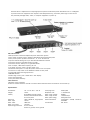
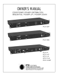
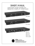
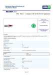
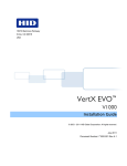
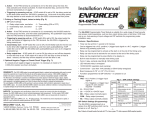
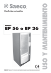
OWNER’S MANUAL
CONDITIONED POWER DISTRIBUTION
SEQUENTIAL POWER UP / POWER DOWN
1450 Lakeside Drive• Waukegan, Illinois 60085 USA
330-677-4424 • 800-321-6699 • Fax: 330-677-4471
http://www.etasys.com E-mail [email protected]
All designs and specifications are subject to change without notice. Copyright © 2006 ETA Systems. 6MAN-021
ETA’s line of Conditioned Power Distribution units are designed to reduce damage to sensitive electronic
equipment from sudden voltage spikes, damaging power surges, and EMI/RFI noise, which is inherent in
utility power lines.
The PD11SP is a sequential four step/stage power up/down conditioned power distribution unit. It
is designed to protect electronic equipment that requires a time-delayed start-up, particularly when high inrush current can potentially damage audio, video, or computer equipment at power up.
PD11SP units are shipped with the ability to be linked or daisy chained. All linked units function as
slaves; however, slaves can be set to specific time delays. Any number of units can be linked together
with a distance of up to 1000 feet between each location (see Fig. 4).
PD11SP Features:
• Microprocessor monitored sequential power distribution system
• Four power up/down steps or stages of distributed and conditioned power
• Four pre-set power up/down intervals of 1, 5, 10 or 30 seconds
• Optional manual settings for up to 240 seconds between intervals
• One dual 20 amp U-grounded outlet per stage
• Full 20 amps, 2400 watts capacity per unit
• 12-gauge, 3-prong, 10-foot, 20-amp power cord. Requires 20 amp circuit and receptacle outlet
• Protected "always on" 15 amp AC power outlet on the front panel
• Total unit 20 amp and 15 amp outlet circuit breakers located on front panel
• Three-stage spike and surge protection
• Two-stage EMI/RFI filtration
• Ground and AC line fault check
• One rack space high
• One year limited warranty
Other Features:
• Remote control operation
• Standard rear panel RCA connectors and 2 screw terminals
Specifications:
Dimensions
Weight
Quality
Electrical
Max. amps
Max. watts
Max. front outlet
Spike/surge protection
19" L x 10" D x 1 3/4" H
10 lbs.
Black powder coated chassis,
anodized aluminum front panel
120V, 50/60 Hz, single phase
20/unit
2400/unit
15 amps
Line to neutral, neutral to
ground, line to ground
Clamping level
Response time
Max. surge voltage
Max. surge current
Max. spike energy
Noise attenuation
Certification ETL listed
200V peak
1 nanosecond
6000V
26,000 amps
630 joules total
Transverse greater
>20dB,1.5kHz to
200 MHz
The PD11SS is a sequential four step/stage power up/down conditioned power distribution unit. It is designed
to protect electronic equipment that requires a time-delayed start-up, particularly when high in-rush current
can potentially damage audio, video, or computer equipment at power up.
PD11SS Features:
• Microprocessor monitored sequential power distribution system
• Four power up/down steps or stages of distributed and conditioned power
• Four pre-set power up/down intervals of 1, 5, 10 or 30 seconds
• Optional manual settings for up to 240 seconds between intervals
• One dual 15 amp U-grounded outlet per stage
• One dual 15 amp "always on" U-grounded outlet
• Full 15 amps, 1800 watts capacity per unit
• 12-gauge, 3-prong, 6-foot, 15-amp power cord
• Protected "always on" 15 amp AC power outlet on the front panel
• Total unit 15 amp outlet circuit breakers located on front panel
• Three-stage spike and surge protection
• EMI/RFI filtration
• Watch dog circuitry with "Go/No Go" L.E.D. display
• One rack space high
• One year limited warranty
Other Features:
• Remote control operation
Access to remote feature is internal to three PC board mounted screw terminals for 3-wire hook-up.
Specifications:
Dimensions
Weight
Quality
Electrical
Max. amps
Max. watts
Max. front outlet
Spike/surge protection
19" L x 10" D x 1 3/4" H
10 lbs.
Finish Black powder coated
chassis, black anodized alumi
num front panel
120V, 50/60 Hz, single phase
15/unit
1800/unit
15 amps
Line to neutral,
neutral to ground, line to ground
Clamping level
Response time
Max. surge voltage
Max. surge current
Max. spike energy
Noise attenuation
Certification
200V peak
1 nanosecond
6000V
12,000 amps
450 joules total
Transverse > 35 dB, 1.5 kHz to
200 MHz
ETL listed
PD11P, PD11VP, PD11LP, PD11LVP Features:
• Light Switch (PD11LP/LVP/LVSP) activates rack illumination; choice of HI or LOW intensity
• Light Tubes (PD11LP/LVP/LVSP) illuminates up to 25 rack spaces
• 4 dual 20 amp U-grounded switched outlets per unit
• 1 dual 15 amp U-grounded "always on" and protected outlet
• Digital Voltmeter Readout (PD11VP/LVP/LVSP) displays incoming line voltage
• Resettable 20 amp thermal circuit breaker; 15 amp for front panel outlet
• Lighted Outlet Power Switch activates protection and filtration to all switch outlets and front panel outlet
• 12-gauge, 3-prong, 10-foot, 20-amp power cord. Requires 20 amp circuit and receptacle outlet
• Protected "always on" 15 amp AC power outlet on the front panel
• Total unit 20 amp and 15 amp outlet circuit breakers located on front panel
• Three-stage spike and surge protection
• Two-stage EMI/RFI filtration
• Ground and AC line fault check
• One rack space high
• One year limited warranty
PD11LVSP Features:
• Microprocessor monitored sequential power distribution system
• Four power up/down steps or stages of distributed and conditioned power
• Four pre-set power up/down intervals of 1, 5, 10 or 30 seconds
• Optional manual settings for up to 240 seconds between intervals
• One dual 120 amp U-grounded outlet per stage
• One dual 20 amp "always on" U-grounded outlet
• Full 20 amps, 2400 watts capacity per unit
• 12-gauge, 3-prong, 10-foot, 20-amp power cord. Requires 20 amp circuit and receptacle outlet
• Protected "always on" 15 amp AC power outlet on the front panel
• Total unit 20 amp and 15 amp outlet circuit breakers located on front panel
• Three-stage spike and surge protection
• Two-stage EMI/RFI filtration
Other Features:
• Remote control operation
• The remote feature is accessed externally through a 3-wire remote block
PD11LVSP/LVP/LP/VP/P Specifications:
Dimensions
Weight
Quality Finish
Electrical
Max. amps
Max. watts
Max. front outlet
Spike/surge protection
Clamping level
Response time
Max. surge voltage
Max. surge current
Max. spike energy
Noise attenuation
Certification
19" L x 10" D x 1 3/4" H
10 lbs.
Black powder coat chassis, black anodized aluminum front panel
120V, 50/60 Hz, single phase
20/unit
2400/unit
15 amps
Line to neutral, neutral to ground, line to ground
200V peak
1 nanosecond
6000V
23,000 amps (PD11LVSP/LVP/VP/LP/P)
630 joules total
Transverse > 20 dB, 1.5 kHz to 200 MHz
ETL listed
Installation Requirements
PD11P, PD11VP, PD11LP, PD11SP, PD11LVP,
PD11LVSP
Plug unit into power source and observe status of four
"Protection" light emitting diodes. The (green) “1st
Stage”, “2nd Stage”, and “GROUND OK” L.E.D.’s
should normally be illuminated and the (red) “FAULT”
L.E.D. should be off. When these indications are present, test the power “On/Off” switch which will illuminate to indicate that power is being supplied to the
switched outlets on the rear of the unit.
A. The “1st Stage” and “2nd Stage” L.E.D.’s
indicate that both the input (1st) and out
put (2nd) stages of circuit protection are
active.
B. The “GROUND OK” L.E.D. indicates that
the chassis is connected to the ground
wire of the supply outlet.
C. Fault conditions are represented by the
following indications:
NOTE: On the PD11SS Model a green L.E.D. located
on the front panel is illuminated (indicating “Protection
On” status) when unit is plugged into a power source
ensuring input and output stages of circuit protection
are active.
Operating Instructions
1. Install in a standard 19" rack or free-standing position.
2. Connect Power Distribution power cord into a 20 amp,
120 volt wall outlet (15 amp for Model PD11SS).
3. Plug sensitive electrical equipment into conditioned
outlets. All models have an additional protected outlet on
the front panel.
4. Move power outlet switch to "ON" position to provide
power to electrical equipment.
5. For illumination, pull out light tubes (PD11LP/LVP/
LVSP) and move light switch to "HI" or "LOW" position.
IMPORTANT! Be sure light switch is in "OFF"
position when light tubes are recessed.
6. Digital voltmeter readout (PD11VP/LVP/LVSP) is
calibrated to nominal 117V at the factory. No adjustment
necessary.
7. Digital voltmeter readout automatically displays
incoming voltage when power cord is connected.
Audio Conditioned Power Distribution is also
designed to protect electronic equipment from potentially
damaging highvoltage spikes and surges.
Sequencing Audio Conditioned Power Distribution is designed to initiate a turn-on cycle, energizing one
circuit immediately with remaining circuits energizing in a
delayed fashion. This allows circuits to stabilize when
powering up and down eliminating that on-rush of power
and potential damage to equipment at output receptacle.
Programming Time Delays
The PD11SP, PD11SS and PD11LVSP come from the
factory set to a 1-second delay for each of the four
outlets to turn on. The following instruction will enable
you to change the amount of time between each outlet
turn on.
• The main power switch must be on
• The sequenced outlets must not be active
• The switches to change the delay time are
to left of the unit and they have green
L.E.D.s in the switch.
• The switches are labeled POWER DOWN/UP
and OFF/ON PRESETS
• The POWER DOWN/OFF is the left switch
• The POWER UP/DOWN is the switch to the
right
Programming Preset Time Delays
Step 1: Depress and hold the DOWN/OFF switch
Step 2: Depress and hold the UP/ON switch
Step 3: Red L.E.D. to the right of the switches will
start to flash
Step 4: When flashing red L.E.D. goes out, release
both switches
Step 5: Both green L.E.D.s on the switches will start
to flash rapidly
Step 6: You are in program mode at this time
Step 7: The red L.E.D.s to the right indicate what the
time delay is set for:
L.E.D. 1 = 1 second delay
L.E.D. 2 = 5 second delay
L.E.D. 3 = 10 second delay
L.E.D. 4 = 30 second delay
Step 8: Depress the UP/ON switch to the right to
increase the time delay
Step 9: Depress the OFF/DOWN switch to the left to
decrease the time delay
Step 10:Depress both OFF and ON switches to finish
the delay programming
Programming Manual Time Delays
Step 1: Follow above instruction to activate L.E.D. 4
Step 2: Depress the UP/ON switch one more time to
activate manual programming time delay mode
Step 3: All 4 red L.E.D.s to the right will be lit to
indicate manual mode
Step 4: The UP/ON switch green L.E.D. will be lit
Step 5: Depress the UP/ON switch to start manual
delay programming—can program from 5
sec. to 240 sec. delay
Step 6: Depress the OFF/DOWN to stop the manual
Delay timing
Step 7: Depress both the OFF and ON switches to
finish programming mode
Three-Wire Remote Control Interface
A three-wire remote control interface is added to the main PC board for the PD11SS, PD11SP AND
PD11LVSP units. This remote control interface is accessible through an external terminal block on the back of the
unit (see Figure 6). This interface requires an external user provided switch, L.E.D., and a three-wire cable to implement. The interface has been tested reliably over 1000 feet with 22-gauge speaker wire (see Figures 1 and 5).
Connect the short minus (-) lead of the L.E.D. and one side of the switch to the COMMON terminal, the
long plus (+) lead of the L.E.D. to the L.E.D. terminal, and finally the other side of the switch to the ON/OFF terminal. When you close the switch, the L.E.D. will begin flashing until all channels have sequenced ON, and then the
L.E.D. will remain ON. When you open the switch the L.E.D. will begin flashing until all channels have sequenced
OFF and then the L.E.D. will remain OFF.
Remote Relay Function Operation (optional)
Using a set of relay contacts that are normally open instead of a switch you can control the PD11SS,
PD11SP AND PD11LVSP units with a relay. When you apply power to the relay the channels will sequence ON, and
when you disconnect power from the relay the channels will sequence OFF. This allows you to interface a PD11SS,
PD11SP AND PD11LVSP unit with other equipment that has dry (normally open) relay contacts (see Figure 2).
Larger Installations In a larger installation, you can control different equipment racks from a remote location by
running three-wire cable from each rack back to the remote location. Then attach an L.E.D. and switch as
before, these would be mounted in the user's control panel, and you now have remote control of each rack in a single location (see Figure 3).
ETA Conditioned Power Distribution...
The Benchmark By Which Professionals Compare.
For over 20 years ETA has developed, manufactured, and sold high amperage theatrical lighting
systems from which have evolved an extensive
line of rack mounted conditioned power distribution products designed to protect today’s sensitive electronic digital equipment.
The “PD” Conditioned Power Distribution Series
easily deals with normal AC line power fluctuations, as well as the more drastic abnormalities
of the spike and surge variety. Also, filtering of
interferences caused by electromagnetic (EMI)
and radio frequency (RFI) transmissions is routinely accomplished. More sophisticated ETA
models utilize microprocessor technology to
regulate AC power and sequence power turnon— reducing high in-rushes of power.
ETA’s sophisticated electronic protection technology is the favorite of professionals who demand flawless operation of digital mixers, processors, amplifiers and PCs—whether in the studio, in the boardroom, on tour, or in a home
entertainment environment.
Power Conditioning Firsts from ETA
• “Always-On” Protected Outlets
• 10 Rear Panel Outlets
• Front Panel Convenience Outlets
• Digital Voltmeter Display Readouts
• Microprocessor Managed Voltage Regulators
• Programmable and Linkable Sequential Turn-on
Models
• Models Adaptable for Multiple AC Adapters
• High Amp Conditioned Models
• Easy Bulb Change Feature
Standard on Every ETA Power Conditioning
Model
• Spike and Surge Protection and EMI/RFI Filtration on All Three Legs of the Incoming AC
Power—A Must to Ensure Protection of Electronic Components and Equipment.
Typical Uses
All Professional Permanent Installations, Recording Studios, Theatres, Schools, Clubs,
Churches, any entertainment venue, business
board rooms, and audio/ visual multi-use presentation rooms.
Portable Applications : On-The-Road Concert
Tours, Bands, and D.J. services.
Other Important Applications: A/V racks, computer networks, and home entertainment centers.
Thank you for choosing ETA Systems
Power Distribution
Your business is appreciated.
Call 1-800-321-6699 for an ETA Full Line
Brochure.
1450 Lakeside Drive• Waukegan, Illinois 60085 USA
330-677-4424 • 800-321-6699 • Fax: 330-677-4471
http://www.etasys.com E-mail [email protected]
All designs and specifications are subject to change without notice. Copyright © 2006 ETA Systems.
6MAN-021
Addendum
NOTE: The following pages are added as
an addendum to the ETA manual. For most reliable performance of ETA Systems sequencing
products, it is recommended that you use one
of the cable types illustrated in the following
pages. When installing any cabling in a plenum
or return air space, it is the responsibility of the
installer to ensure that Teflon jacketed cable is
used where required by fire codes. ETA Systems assumes no responsibility for code violations or hazards that result from improper selection or installation of signaling cable.
8489 Non-Paired - Audio, Control and Instrumentation Cable
For more information please
call
1-800-Belden1
See Put-ups and Colors
Related Documents : No. 1.pdf
Description:
18 AWG stranded (19x30) tinned copper conductors, conductors cabled, PVC insulation, PVC jacket.
PHYSICAL CHARACTERISTICS:
CONDUCTOR:
Number of Conductors
4
Total Number of Conductors
4
AWG
18
Stranding
19x30
Conductor Material
TC - Tinned Copper
INSULATION:
Insulation Material
PVC - Polyvinyl Chloride
Nom. Insulation Wall Thickness
.017 in.
OVERALL CABLING:
Overall Cabling Lay Length
3 in.
Overall Cabling Twists/ft.
4
Overall Cabling Color Code Chart :
Number
1
2
Color
Black
White
Number
3
4
OUTER SHIELD:
Outer Shield Material
Unshielded
OUTER JACKET:
Outer Jacket Material
PVC - Polyvinyl Chloride
Outer Jacket Nominal Wall Thickness
.032 in.
OVERALL NOMINAL DIAMETER:
Overall Nominal Diameter
.257 in.
MECHANICAL CHARACTERISTICS:
Page 1 of 3
Color
Red
Green
8489 Non-Paired - Audio, Control and Instrumentation Cable
Operating Temperature Range
-20°C To +60°C
UL Temperature Rating
60°C (UL AWM Style 2598)
Bulk Cable Weight
44.1 lbs/1000 ft.
Max. Recommended Pulling Tension
83 lbs.
Min. Bend Radius (Install)
2.6 in.
APPLICABLE SPECIFICATIONS AND AGENCY COMPLIANCE:
APPLICABLE STANDARDS:
NEC/(UL) Specification
CMG
CEC/C(UL) Specification
CMG
AWM Specification
UL Style 2598 (300 V 60°C)
EU CE Mark (Y/N)
Yes
EU RoHS Compliant (Y/N)
Yes
EU RoHS Compliance Date (mm/dd/yyyy):
04/01/2005
FLAME TEST:
C(UL) Flame Test
FT4
PLENUM/NON-PLENUM:
Plenum (Y/N)
N
Plenum Number
88489, 82489
ELECTRICAL CHARACTERISTICS:
Nom. Capacitance Conductor to Conductor @ 1 KHz
26 pF/ft
Nom. Conductor DC Resistance @ 20 Deg. C
6.3 Ohms/1000 ft
Max. Operating Voltage - UL
300 V RMS (UL AWM Style 2598)
Max. Recommended Current
4 Amps per conductor @ 25°C
PUT-UPS AND COLORS:
Item
Description
8489 060100
4 #18 PVC PVC
Put-Up (ft.)
100
Ship Weight (lbs.)
5.1
Jacket Color
CHROME
Notes
8489 0601000
4 #18 PVC PVC
1000
48
CHROME
C
8489 060250
4 #18 PVC PVC
250
12
CHROME
8489 060500
4 #18 PVC PVC
500
24
CHROME
8489 060U1000
4 #18 PVC PVC
U1000
46
CHROME
8489 060U500
4 #18 PVC PVC
U500
23.5
CHROME
C = CRATE REEL PUT-UP.
Revision Number: 2
Revision Date: 05-16-2005
Page 2 of 3
C
8489 Non-Paired - Audio, Control and Instrumentation Cable
© Copyright 2006 Belden, Inc
All Rights Reserved.
Although Belden ("Belden") makes every reasonable effort to ensure their accuracy at the time of this publication, information and
specifications described herein are subject to error or omission and to change without notice, and the listing of such information and
specifications does not ensure product availability.
Belden provides the information and specifications herein on an "AS IS" basis, with no representations or warranties, whether express,
statutory or implied. In no event will Belden be liable for any damages (including consequential, indirect, incidental, special, punitive, or
exemplary damages) whatsoever, even if Belden has been advised of the possibility of such damages, whether in an action under contract,
negligence or any other theory, arising out of or in connection with the use, or inability to use, the information or specifications described
herein.
All sales of Belden products are subject to Belden's standard terms and conditions of sale.
Belden believes this product to be in compliance with the following environmental regulations: California Proposition 65 Consent Judgment
For Wire & Cable Mfgs.(San Francisco Superior Court Nos. 312962 And 320342); EU RoHS (Directive 2002/95/EC, 27-Jan2003);Material manufactured prior to the compliance date may still be in stock at Belden facilities and in our Distributor's inventory. EU
ELV (Directive 2000/53/EC, 18-Sept-2000); EU WEEE (Directive 2002/96/EC, 27-Jan-2003); And EU BFR (Directive 2003/11/EC, 6-Feb2003). The information provided in this Product Disclosure, and the identification of materials listed as reportable or restricted within the
Product Disclosure, is correct to the best of Belden's knowledge, information and belief at the date of its publication. The information
provided in the Product Disclosure is designed only as a general guide for the safe handling, storage, and any other operation of the product
itself or the one that it becomes a part of. This Product Disclosure is not to be considered a warranty or quality specification. Regulatory
information is for guidance purposes only. Product users are responsible for determining the applicability of legislation and regulations
based on their individual usage of the product.
Belden declares this product to be in compliance with EU LVD (Low Voltage Directive 73/23/EEC), as amended by directive 93/68/EEC.
Page 3 of 3
COMMUNICATION & CONTROL
UL TYPE CM
UL AWM 2509, CSA CMG FT 4
RoHS COMPLIANT, 300 VOLT
MULTICONDUCTOR, UNSHIELDED
PVC/PVC
CHARACTERISTICS
182
OPERATING TEMPERATURE:
■ –20°C to 80°C – AWM
■
75°C – CM
VOLTAGE RATING:
■ 300 Volt – CM
■ 150 Volt – CL2
COLOR DESCRIPTION:
■ Color Code: Chart D Page 375
■ Jacket Color: Gray
PRODUCT DESCRIPTION:
■ Conductor: Stranded Tinned Copper
■ Insulation: Color-Coded PVC
■ Jacket: PVC
SPECIFICATIONS
■
■
■
■
■
■
■
UL Type CM, AWM 2509 (18 & 16 AWG)
UL Type CL2, (14 & 12 AWG)
CSA CMG FT4 (18 & 16 AWG)
CSA AWM I A/B, II A/B FT4 (14 & 12 AWG)
Passes UL Vertical Tray Flame Test
“C” Suffix Indicates CM or CL2 Rating as Applicable
RoHS Compliant
80°C 300V - UL 2509 - NEC TYPE CM
18 AWG (0,81mm2), 16/30 (16x0,25mm), Insulation Thickness: 0.016" (0,41mm)
Alpha
Part No.
1897C
1898C
1898/4C
1898/5C
1898/6C
1898/7C
1898/8C
1898/9C
1898/10C
1898/12C
1898/15C
1898/19C
1898/25C
1899C
1899/3C
1899/4C
AVAILABILITY
■
100 ft (30,5m), 500 ft (152m),
1000 ft (305m) put-ups
2
3
4
5
6
7
8
9
10
12
15
19
25
Jacket Thickness
Inches
mm
Diameter
Inches
mm
0.020
0.020
0.020
0.020
0.020
0.020
0.025
0.025
0.025
0.025
0.030
0.030
0.035
0.20
0.21
0.24
0.26
0.29
0.29
0.31
0.34
0.37
0.38
0.44
0.47
0.56
0,50
0,50
0,50
0,50
0,50
0,50
0,63
0,63
0,63
0,63
0,76
0,76
0,88
5,0
5,3
6,1
6,6
7,4
7,4
8,0
8,8
9,4
9,8
11,3
11,9
14,1
80°C 300V - UL 2509 - TYPE CM
16 AWG (1,31mm2), 19/0.0117 (19x0,29mm), Insulation Thickness: 0.016" (0,41mm)
Alpha
Part No.
®
No. of
Cond.
No. of
Cond.
2
3
4
Jacket Thickness
Inches
mm
0.020
0.020
0.020
0,50
0,50
0,50
Diameter
Inches
mm
0.22
0.24
0.27
5,7
6,3
6,9
80°C 300V - UL TYPE CL2
14 AWG (2,08mm2), 41/30 (41x0,25mm), Insulation Thickness: 0.020" (0,50mm)
Alpha
Part No.
1891C
1891/3C
No. of
Cond.
2
3
Jacket Thickness
Inches
mm
Diameter
Inches
mm
0.020
0.020
0.26
0.28
0,50
0,50
6,6
7,1
80°C 300V - UL TYPE CL2
12 AWG (3,31mm2), 65/30 (65x0,25mm), Insulation Thickness: 0.020" (0,50mm)
Alpha
Part No.
1892C
1892/3C
No. of
Cond.
2
3
Jacket Thickness
Inches
mm
Diameter
Inches
mm
0.020
0.020
0.30
0.32
Toll Free: 1-800-52 ALPHA • Telephone: 908-925-8000 • Fax: 908-925-6923
Europe/UK Telephone: +44 (0) 1932 772422 • Europe/UK Fax: +44 (0) 1932 772433
0,50
0,50
7,6
8,1
Web Site: www.alphawire.com
Email: [email protected]