1
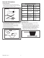
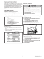
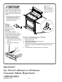
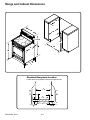
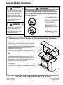
This manual covers general information on Freestanding Electric BIG OVEN. Refer to individual Technical Sheets for information on specific models. Service Electric Freestanding BIG OVEN™ Service Manual for Amana® This manual is to be used by qualified appliance technicians only. Amana does not assume any responsibility for property damage or personal injury for improper service procedures done by an unqualified person. RS2320006 Revision 0 August 2001 Important Information Pride and workmanship go into every product to provide our customers with quality products. It is possible, however, that during its lifetime a product may require service. Products should be serviced only by a qualified service technician who is familiar with the safety procedures required in the repair and who is equipped with the proper tools, parts, testing instruments and the appropriate service manual. REVIEW ALL SERVICE INFORMATION IN THE APPROPRIATE SERVICE MANUAL BEFORE BEGINNING REPAIRS. Important Notices for Consumers and Servicers ! WARNING To avoid risk of serious injury or death, repairs should not be attempted by an unauthorized personal, dangerous conditions (such as exposure to electrical shock) may result. ! CAUTION Amana will not be responsible for any injury or property damage from improper service procedures. If performing service on your own product, assume responsibility for any personal injury or property damage which may result. To locate an authorized servicer, consult your telephone book or the dealer from whom you purchased this product. For further assistance, contact: 1 (800) 628-5782 first, if no answer call number listed below. CONSUMER AFFAIRS DEPT. AMANA APPLIANCES AMANA, IOWA 52204 OR CALL 1 (800) 843-0304 If outside the United States contact: AMANA ATTN: CONSUMER AFFAIRS DEPT AMANA, IOWA 52204, USA Telephone: (319) 622-5511 Facsimile: (319) 622-2180 TELEX: 4330076 AMANA CABLE: "AMANA", AMANA, IOWA, USA Recognize Safety Symbols, Words, and Labels ! DANGER DANGER—Immediate hazards which WILL result in severe personal injury or death. ! WARNING WARNING—Hazards or unsafe practices which COULD result in severe personal injury or death. ! CAUTION CAUTION—Hazards or unsafe practices which COULD result in minor personal injury or product or property damage. RS2320006 Rev. 0 2 Table of Contents Important Information ................................................. 2 Important Safety Information ...................................... 4 ALL APPLIANCES ............................................... 5 SURFACE COOKING UNITS .............................. 5 OVENS ................................................................ 5 VENTILATION HOODS ....................................... 5 In Case of Fire ..................................................... 5 Precautions ......................................................... 5 General Information Cooking Utensils .................................................. 6 Pan Bottom Test .................................................. 6 Oven Rack Placement ......................................... 7 Pan Placement .................................................... 7 Removing Oven Door .......................................... 7 Replacing Oven Door ........................................... 7 Component Testing Information ................................. 8 Troubleshooting Procedures ...................................... 9 Disassembly Procedures Oven Door Handle, Outer/Inner Glass, and Door Hinges ....................................................... 11 Reverse Procedure to Reassemble Oven Door .. 12 Oven Door Gasket ............................................. 12 Electronic Control .............................................. 12 Infinite Switch .................................................... 12 Indicator Light .................................................... 12 Maintop .............................................................. 13 Door Latch Motor, Plunger Light Switch, and Latch Switch ...................................................... 13 Bake Element .................................................... 13 Broil Element ..................................................... 14 Sensor, Oven Control ........................................ 14 Oven Light and Oven Light Socket ..................... 14 Flue ................................................................... 14 Leveling Leg Bracket ......................................... 14 Front Frame and Oven Liner .............................. 14 Side Panel ......................................................... 14 Storage Drawer Removal ................................... 15 Storage Drawer Tracks ...................................... 15 Power Cord ........................................................ 15 Removing and Replacing Range ........................ 15 Appendix A Installation Instructions ..................................... A-2 Appendix B Care and Cleaning ............................................ B-2 Appendix C Genesis Control ................................................ C-2 Appendix D Sigma Control ................................................... D-2 3 RS2320006 Rev. 0 Important Safety Information ! ! WARNING To reduce the risk of the appliance tipping, it must be secured by a properly installed anti-tip bracket(s). To make sure bracket has been installed properly, remove the storage drawer or decorative panel and look under the range with a flashlight. Bracket(s) must be engaged in the rear corner of the range. To avoid risk of electrical shock, personal injury, death, or property damage, verify wiring is correct, if components were replaced. Verify proper complete operation of unit after servicing. ! • ALL RANGES CAN TIP • INSTALL ANTI-TIP BRACKET(S) PACKED WITH RANGE ! • SEE INSTALLATION INSTRUCTIONS WARNING WARNING To avoid risk of electrical shock, personal injury, or death, make sure your range has been properly grounded and always disconnect it from main power supply before any servicing. ! ALL APPLIANCES 1. Proper Installation—Be sure your appliance is properly installed and grounded by a qualified technician. 2. Never Use Your Appliance for Warming or Heating the Room. 3. Do Not Leave Children Alone—Children should not be alone or unattended in the area where the appliance is in use. They should never be allowed to sit or stand on any part of the appliance. 4. Wear Appropriate Apparel—Loose fitting or hanging garments should never be worn while using appliance. 5. User Servicing—Do not repair or replace any part of the appliance unless specifically recommended in the manual. All other servicing should be referred to a qualified technician. 6. Storage in or on Appliance—Flammable materials should not be stored in an oven or near surface units. 7. Do Not Use Water on Grease Fires—Smother fire or flame, or use dry chemical or foam-type extinguisher. 8. Use Only Dry Potholders—Moist or damp potholders on hot surfaces may result in burns from steam. Do not let potholder touch elements. Do not use a towel or other bulky cloth. WARNING This appliance contains or produces a chemical or chemicals which can cause death or serious illness and which are known to the state of California to cause cancer, birth defects or other reproductive harm. To reduce the risk from substances in the fuel or from fuel combustion make sure this appliance is installed, operated, and maintained according to the instructions in this booklet. ! CAUTION Do not store items of interest to children in cabinets above a range or behind the backguard of a range. Children climbing on the range to reach items could be seriously injured. RS2320006 Rev. 0 CAUTION DO NOT TOUCH HEATING ELEMENTS OR INTERIOR SURFACES OF OVEN—Oven heating elements may be hot though they are dark in color. Interior surfaces of an oven may become hot enough to cause burns. During and after use, do not touch, or let clothing or other flammable materials touch heating elements or interior surfaces of oven until they have had enough time to cool. Other range surfaces that may become hot enough to cause burns are the oven door and oven. To avoid personal injury, do not sit, stand or lean on oven door or oven drawer. ! CAUTION DO NOT TOUCH SURFACE UNITS OR AREAS NEAR UNITS—Surface units may be hot though they are dark in color. Areas near surface units may become hot enough to cause burns. During and after use, do not touch, or let clothing touch or other flammable materials contact surface units or areas near surface units until they have had enough time to cool. These areas include the rangetop and backguard. • INJURY TO PERSONS COULD RESULT ! WARNING 4 Important Safety Information SURFACE COOKING UNITS In Case of Fire 1. Use Proper Pan Size—This appliance is equipped with one or more surface units of different size. Select utensils having flat bottoms large enough to cover the surface unit heating element. The use of undersized utensils will expose a portion of the heating element to direct contact and may result in ignition of clothing. Proper relationship of utensil to burner will also improve efficiency. 2. Never Leave Surface Units Unattended—Boilover causes smoking and greasy spillovers that may ignite. 3. Make Sure Reflector Pans or Drip Bowls Are In Place—Absence of these pans or bowls during cooking may subject wiring or components underneath to damage. 4. Protective Liners—Do not use aluminum foil to line oven bottom. Improper installation of these liners may result in a risk of electrical shock or fire. 5. Glazed Cooking Utensils—Do not use glass, ceramic, earthware, or other glazed utensils. They can damage smoothtop and can break due to sudden change in temperature. 6. Utensil Handles Should be Turned Inward and Not Extend Over Adjacent Surface Units—To reduce the risk of burns, ignition of flammable materials, and spillage due to unintentional contact with the utensil, the handle of a utensil should be positioned so that it is turned inward, and does not extend over adjacent surface units. 7. Do Not Soak Removable Heating Elements—Heating elements should never be immersed in water. Fires can occur as a result of over cooking or excessive grease. Though a fire is unlikely, if one occurs, proceed as follows: Surface Element Fire 1. Smother the fire with a nonflammable lid or baking soda, or use a Class ABC or BC extinguisher. Not water. Not salt. Not flour. 2. As soon as it is safe to do so, turn the surface controls to “OFF”. Oven Fires 1. If you see smoke from your oven, do not open oven door. 2. Turn oven control to “OFF”. 3. As an added precaution, turn off power at main circuit breaker or fuse box. 4. Turn on vent to remove smoke. 5. Allow food or grease to burn itself out in oven. Do not open oven door. 6. If smoke and fire persist, call fire department. 7. If there is any damage to components, call an authorized servicer before using range. Precautions • Do not cook food directly on range top surface, always use cookware. • Do not mix household cleaning products. Chemical mixtures may interact with objectionable or even hazardous results. • Do not put plastic items on warm cooking areas. They may stick and melt. • Do not slide rough objects across range top surface. Scratching or metal marking can result. • Do not leave fat heating unless you remain nearby. Fat can ignite if overheated by spilling onto hot surfaces. • Do not allow pots to boil dry as this can cause damage to cooking surface and pan. • Do not use range top surface as a cutting board. • Do not use range for storage or as a display counter. OVENS 1. Use Care When Opening Door—Let hot air or steam escape before removing or replacing food. 2. Do Not Heat Unopened Food Containers—Buildup of pressure may cause container to burst and result in injury. 3. Keep Oven Vent Ducts Unobstructed. 4. Placement of Oven Racks—Always place oven racks in desired location while oven is cool. If rack is removed while oven is hot, do not let potholder contact hot heating element in oven. VENTILATION HOODS 1. Clean Ventilation Hoods Frequently—Grease should not be allowed to accumulate on hood or filter. 2. When flaming foods under hood, turn fan off. The fan, if operating, may spread the flame. 5 RS2320006 Rev. 0 General Information Cooking Utensils Utensil Material Characteristics Type Temperature Uses Response Aluminum Heats and Frying, Braising, Cools Quickly Roasting Cast Iron Heats and Low Heat Cools Slowly Cooking, Frying Copper Tin Heats and Gourmet Lined Cools Quickly Cooking, Wine Sauces, Egg Dishes Enamelware Depends on Low Heat Base Metal Cooking Ceramic Heats and Low Heat (Glass) Cools Slowly Cooking Heats and Soups, Sauces, Stainless Steel Cools at Vegetables, Moderate Rate General Cooking • Use proper pan size. Do not use a pan that has a bottom smaller than element. Do not use utensils that overhang element by more than 1 inch. 1" Less than 1" overhang 2" More than 1" overhang Pan Bottom Test • Use care when using glazed cooking utensils. Some glass, earthenware, or other glazed utensils break due to sudden temperature changes. • Select utensils without broken or loose handles. Handles should not be heavy enough to tilt pan. • Select utensils with flat bottoms. • Do not use a wok with a ring stand. Determine if pan has a flat bottom. For best cooking results, use a pan with a flat bottom. 1. Rotate a ruler along bottom of pan. If pan is not flat, gaps between bottom of pan and edge of ruler occur. 2. A small groove or mark on a pan does not effect cooking times. However, if a pan has a gap, formed rings, or an uneven bottom, it does not cook efficiently and in some cases may not boil water. Do not use a wok with a ring stand. Use a flat bottom wok. RS2320006 Rev. 0 6 General Information Follow these recommendations only as a guide for times and temperature. Times, rack position, and temperatures may vary depending on conditions and food type. For best results, always check food at minimum time. When roasting, choose rack position based on size of food item. Removing Oven Door ! CAUTION To avoid personal injury or property damage, handle oven door with care. • Door is heavy and can be damaged if dropped. • Avoid placing hands in hinge area when door is removed. Hinge can snap closed and pinch hands. • Do not scratch or chip glass, or twist door. Glass may break suddenly. • Replace door glass if damaged. Oven Rack Placement Position oven rack before turning on oven. 1. Pull rack forward to stop position. 2. Raise front edge of rack and pull until rack is out of oven. 3. Place rack in new rack position. • Curved edge of rack must be toward rear of oven. 1. Pull out or remove storage drawer to avoid damaging finish. 2. Fully open oven door. 3. Push hinge locks down toward door frame, to the unlocked position. • This may require a flatblade screwdriver. 4. Firmly grasp both sides of top of oven door. 5. Close door to first stop position. 6. Lift door up until hinge arm is clear of the slot. Oven Frame Pan Placement Hinge Lock • Keep pans and baking sheets 2 inches from oven walls. • Stagger pans placed on different racks so one is not directly over the other. Oven Door Replacing Oven Door 1. Grasping door top firmly, seat indentation of hinge arm into bottom edge of the hinge slot. • Door should be at the first stop position angle. 2. Fully open oven door. 3. Push hinge locks up against the front frame of the oven cavity to locked position. 4. Close oven door. 7 RS2320006 Rev. 0 Component Testing Information ! WARNING To avoid risk of electrical shock, personal injury or death; disconnect power to oven before servicing, unless testing requires it. Refer to Technical Sheet or Parts Manual for replacement components specifications. Illustration Component Oven light socket Test Procedure Remove one wire from receptacle and test resistance of terminals. Measure voltage at oven light........... Oven indicator light and Surface indicator light Rocker switch Ribbon radiant elements, limiters are not replaceable. Infinite switch Control limit Bake element Remove one lead from switch terminal and measure resistance across terminals. Measure voltage at indicator light ..... Measure continuity of switch positions: Closed ............................................. Open ............................................... Remove one wire lead from element and measure resistance of the element. Verify supply voltage ........................ Remove wiring from terminals H1 and H2. Connect Volt ohms meter to H1 and H2. Measure the following for voltages at LO, MED, HI: H1 to H2 ......................................... Normally Closed Verify proper operation. Closed ............................................ Open .............................................. Disconnect wire leads to element and measure resistance of terminals. Measure voltage at bake element..... Broil element Disconnect wire leads to element and measure resistance of terminals. Measure voltage at broil element...... RS2320006 Rev. 0 Oven temperature sensor Measure resistance .......................... Auto latch assembly Motor switch Unlocked ..................................... Locked ........................................ Door switch Door closed................................. Door open ................................... 8 Results Indicates continuity with bulb screwed in. 120 VAC, see wiring diagram for terminal identification. If no voltage is present at oven light, check wiring or light switches. Switch closed: 0 Ω Switch open: Infinite resistance If voltage is present and light does not operate. Replace light. If no voltage is present at indicator light check wiring. Continuity, if not replace. Infinite, if not replace. Continuity, if not replace. 1200W: 44 to 49 Ω Approximately 1500W: 36 to 40 Ω Approximately 2000W: 26 to 30 Ω Approximately 2500W: 20 to 23 Ω Approximately 240 VAC Time On LO 5% MED (4-5) 50% HI 100% Time Off 95% 50% 0% 240 VAC, if not replace switch. Continuity Infinite If open at room temperature, replace. Continuity, approximately 20 Ω, if not replace. 240 VAC, see wiring diagram for terminal identification. If no voltage is present at bake element check wiring. Continuity, approximately 19 Ω, if not replace. 240 VAC, see wiring diagram for terminal identification. If no voltage is present at broil element check wiring. Approximately 1100 Ω at room temperature 75°F. COM − N.O. continuity COM − N.O. open COM − N.C. continuity COM − N.C. open Troubleshooting Procedures ! WARNING To avoid risk of electrical shock, personal injury or death; disconnect power to oven before servicing, unless testing requires it. Problem Surface element does not heat No bake operation No broil operation Oven light does not operate Appliance not working Possible Cause • Open element..................................... Correction Check element for continuity, replace if failed. Verify all connections are clean and tight, replace broken wiring. Check infinite switch, replace if failed. Check element for continuity, replace if failed. Verify all connections are clean and tight, replace broken wiring. Check element for continuity, replace if failed. Verify all connections are clean and tight, replace broken wiring. Check lamp and replace if necessary. Check switch contacts. Check for broken and loose or dirty connections. Check light socket for continuity. • • Loose wire connection or broken wire . • • Failed infinite switch............................ • • Open bake element ............................ • • Loose wire connection or broken wire . • • Open broil element ............................. • • Loose wire connection or broken wire . • • Failed oven lamp ................................ • • Failed light switch ............................... • Failed wiring ....................................... • • • Failed light socket ............................... • • Power outage .................................... • Make sure appliance is plugged in. Verify that circuit breaker is not tripped. • Replace household fuse but do not change fuse capacity. Frequent cycling of surface element or warming zone • Normal............................................... • Element cycles to maintain proper heat and to prevent damage to smoothtop. Oven not working • Programming error............................. • Shut off power to oven for five minutes by switching off circuit breaker. Reset circuit breaker and try oven again. Clock and timer not working • Power outage...................................... • Make sure appliance is plugged in. Verify that circuit breaker is not tripped. Replace household fuse but do not change fuse capacity. • See appropriate control appendix and if continues, contact service department. 9 RS2320006 Rev. 0 Troubleshooting Procedures ! WARNING To avoid risk of electrical shock, personal injury or death; disconnect power to oven before servicing, unless testing requires it. Problem Melted top door trim Possible Cause • Miss-aligned door gasket ..................... Correction • Replace door gasket. • Check door hinges. Self-clean cycle not working • Programming error............................... • Shut off power to oven for five minutes by switching off circuit breaker. Reset circuit breaker and try oven again. Oven door will not unlock • Oven is self-cleaning............................ • Allow cycle to complete. • Oven still hot ........................................ • Will not unlatch until a cooler temperature has been reached. Do not force door open, this will void warranty. May blow cooler air on latch area with a hair dryer at cool setting to quicken process. • Too much soil, grime left in oven .......... • Wipe out and remove excess soil prior to running self-clean cycle. • Soot remains in oven after cycle........... • Normal. Locked light displayed • Door locked.......................................... • If oven is hot, allow to cool rather than trying to force door latch open. Display flashing • Power failure reset clock ...................... • Press CLOCK pad. F-(numeric) display • Service code ........................................ • Shut off power to oven for one to two minutes, by switching off circuit breaker. Reset breaker. Oven not clean after a self-clean cycle • See appropriate control appendix and if continues, contact service department. Oven smokes the first few times used RS2320006 Rev. 0 • Normal................................................. 10 • Minor smoking is normal the first few times the oven is used. Disassembly Procedures ! To avoid risk of electrical shock, personal injury or death; disconnect power supply source before servicing, unless testing requires it. WARNING Oven Door Handle, Outer/Inner Glass, and Door Hinges NOTE: May need to loosen screws in bottom glass retainer. 8. Remove screws and neoprene washer from the bottom of OVEN DOOR HINGE and one screw securing oven door hinge to the door assembly. 1. Open or remove storage drawer to avoid damaging finish. 2. Fully open the oven door, while open rotate both hinge locking tabs into the LOCK position. NOTE: Hinges are interchangeable. 9. Remove screws securing top of door trim. Lift up and twist trim towards bottom of door to disengage plastic finger tabs. 10.All outer perimeter door trim can now be removed. 11. After removing the OFFSET screws from left and right door glass trim, access is gained to the door glass heat shield. 12.Remove screws from each side and screws from top of door glass heat shield. Note position of plastic door handle supports remove same. 13.Lift out galvanized insulation retainer and fiberglass insulation. 14.Remove the tempered glass panes individually as well as the glass frame. Hinge Lock Oven Door 3. Close oven door about all the way. The hinge locking tabs will prevent the door closing completely. 4. Lift up equally on both sides of oven door. Hinges will disengage from hinge receivers and oven door can be removed. 5. Place oven door, with outer door glass facing downward on a padded flat surface. 6. While supporting outer door glass, remove screws securing left and right side the OVEN DOOR HANDLE. 7. Again support outer door glass and turn door assembly so outer door glass is facing upward and remove outer oven door glass. NOTE: Position replacement hinges into LOCK position by using channel lock pliers PRIOR to installing oven door on range. Door Handle Screw Side Door Trim Top Door Trim NOTE: Tempered glass panes do not have an inner or outer side. Be careful of fingerprints before reassembly. Window Glass Door Hinge Heat Shield Bushing Oven Door Window Oven Door Backer Window Frame Door Handle Door Hinge Side Door Trim Door Glass Heat Shield Glass Support 11 RS2320006 Rev. 0 Disassembly Procedures ! To avoid risk of electrical shock, personal injury or death; disconnect power supply source before servicing, unless testing requires it. WARNING Reverse Procedure to Reassemble Oven Door 4. Place control panel on a protective padded surface with the control down. Remove screws securing electronic control to mounting bracket. There is sufficient extra wire length to move electronic control out of the way while installing new control. Transfer electrical wires/connectors one at a time to new control. Oven Door Gasket NOTE: When reinstalling control panel, be certain the fiberfax insulation and its galvanized retainer is above the flue cutout in control panel. Insulation and retainer are NOT visible when correctly positioned. Verify backguard heat shield (above flue) is inside backguard panel and not visible when installed. Position slot on oven door hinge arms into the hinge receivers. When slot is engaged into the hinge receivers, open the door just far enough to rotate both hinge locking tabs to the UNLOCK position. The braided fiberglass oven door gasket is clipped at intervals in holes around the front of the oven liner then inserted into a 3/8inch holes at the bottom. A 6 1/2 inch gasket void at the bottom does not interfere with sealing of oven to door. 1. Unclip original gasket from front frame and pullout ends from 3/8inch holes. 2. Remove two knurled nuts securing oven bottom in position. Remove oven bottom. 3. Divide oven gasket in half and insert center clip into top center hole in the front frame. Proceed inserting clips left and right. 4. Push gasket through the 3/8inch holes. From behind the holes gently pull on the gasket ends to provide a neat appearance. Then tuck the ends between cross brace and front frame. Assure that gasket ends are not visible through air intake slots. If so, reposition prior to installing oven bottom and oven door. Electronic Control 1. Turn off electric supply to oven. 2. Using a stubby phillips screwdriver remove the offset screws from the bottom front of control panel. 5. Reverse procedure to reattach control panel to range. Infinite Switch 1. Turn off power to unit. 2. Remove backguard, see "Electronic Control" procedure. 3. Disconnect and label wire terminals. 4. Remove infinite switch knob from infinite switch. 5. Remove screws in front securing infinite switch. 6. Reverse procedure to reinstall. Indicator Light 1. Turn off power to unit. 2. Remove backguard, see "Electronic Control" procedure. 3. Disconnect and label wire terminals. 4. Slide indicator light sideways to release from indicator light lens. 5. Reverse procedure to reinstall. Clock Infinite switch Indicator light Offset screws Rocker switch 3. Rotate bottom of control panel outward, then lift up to disengage top tabs. RS2320006 Rev. 0 12 Disassembly Procedures ! WARNING To avoid risk of electrical shock, personal injury or death; disconnect power supply source before servicing, unless testing requires it. Maintop Door Latch Motor, Plunger Light Switch, and Latch Switch NOTE: Requires range to be moved out away from the wall. 1. Turn power off to unit. 2. Slide range forward on slide guards. NOTE: Usage of slide guards, prevents the unit from damaging the floor. 3. Unplug the power cord. 4. Remove screws securing maintop to oven frame, located in front, above the oven door. 5. Raise and support the maintop to gain access to wire terminals. 6. Label and disconnect wire terminals from elements. 7. Remove screws securing elements support brackets to the maintop. Type of brackets may vary. 1. Disconnect electrical supply to range. 2. Remove maintop, see Maintop procedure. 3. Remove screws in front and on right side securing latch mechanism to range front frame and galvanized insulation retainer. 4. Carefully maneuver assembly to the rear to clear door catch and light switch plunger. 5. Move assembly to the left side then lift up on the right side. After clearing the insulation retainer turn assembly upside down to access screws securing components to mounting plate. 6. Reverse procedures to reassemble. NOTE: When removing elements from maintop mark or label elements for reassembling. NOTE: Latch motor, rod, and catch are not sold separately. Bake Element 1. 2. 3. 4. Turn off power to unit. Remove all utensils and racks from oven cavity. Remove oven door, see "Oven Door" procedure. Remove screws securing oven bottom to the bottom of the oven cavity. 5. Remove bake element cover. Push downward on the front portion of the bake element cover. This will raise the rear of the cover. Grasp the back portion of the cover and slide cover towards the rear of the oven cavity, releasing the front portion of the cover from the oven cavity. Remove the cover from the oven cavity. 6. Remove screws securing bake element to the oven cavity. 7. Pull element and wires into oven cavity. Typical maintop assembly 8. Remove screws securing hinge to the maintop. 9. Remove maintop. 10.Reverse procedure to reinstall. NOTE: Pull bake element forward enough to disconnect terminals on each element leg. 8. Disconnect terminals from each element leg. 9. Reverse procedure to reinstall bake element. 13 RS2320006 Rev. 0 Disassembly Procedures ! WARNING Broil Element 1. Turn off power to unit. 2. Remove screw securing broil element to rear of oven wall. 3. Remove screws securing element hanging clip to oven cavity. 4. Pull broil element forward enough to disconnect terminals on each element leg. 5. Reverse procedure to reinstall broil element. Sensor, Oven Control 1. Remove screws securing SENSOR to oven liner. 2. Gently pull wires forward to access the two pin polarized disconnect plug. 3. Disconnect and reconnect new sensor. 4. Reverse procedure to reassemble. To avoid risk of electrical shock, personal injury or death; disconnect power supply source before servicing, unless testing requires it. 5. Reverse procedures to reassemble. Flue NOTE: Requires removal of range. NOTE: Self-clean cycle is highly recommended before replacing flue. Ease of disassembly and reassembly is much easier. 1. 2. 3. 4. Disconnect electrical supply to range. Using floor protection guides, slide range forward. Remove backguard shield from rear of backguard. Remove screws securing smoke eliminator located inside, at top of oven cavity. 5. Pull flue out away from the range. Replacing Flue 1. Place a thin but rugged piece of cardboard in the slot where flue goes, this holds the insulation up and out of the way for reassembly. 2. Align the smoke eliminator screen through oven and secure with screws. 3. Reassemble in reverse order. Leveling Leg Bracket NOTE: Verify disconnect terminal is behind the rear insulation retainer. Remove screws securing bracket to chassis. Oven Light and Oven Light Socket Front Frame and Oven Liner are NOT field replaceable on these units. 1. Disconnect electrical supply to oven. Front Frame and Oven Liner Side Panel 2. Wearing protective gloves unscrew the knurled mason jar lens cover counterclockwise about 3/4 turn and remove. Unscrew old oven light bulb. 3. Remove screws securing oven light socket to the oven cavity. 4. Pull oven light socket out through the front and disconnect wire terminals from socket. 1. Remove maintop, see Maintop procedure steps 1 7. 2. Remove lower access panel, located on the rear of unit. 3. Remove screws securing backguard bracket to side panel. 4. Remove oven door from unit and slide oven drawer outward to gain access to screws. 5. Remove screws securing side panel to oven chassis. Screws are located on top, front, and back of unit. 6. Remove side panel by pulling outward on the back of panel and sliding panel forward. 7. Reverse procedure to reassemble. NOTE: Reposition fiberglass insulation around oven light socket to eliminate possibility of heat related problems. RS2320006 Rev. 0 14 Disassembly Procedures ! WARNING To avoid risk of electrical shock, personal injury or death; disconnect power supply source before servicing, unless testing requires it. Storage Drawer Removal Removing and Replacing Range 1. Pull drawer out until it stops. 2. Grasp drawer sides near back of drawer and lift up and out. 3. Reverse procedure to reinstall storage drawer. 1. Disconnect power to range. 2. Slide range forward on slide guards. NOTE: Usage of slide guards, prevents the unit from damaging the floor. 3. Unplug range cord and place range aside. 4. Remove anti-tip bracket. 5. Install anti-tip bracket into new location using instructions provided with bracket. 6. To reinstall range, follow instructions in Installation section of this manual. Storage Drawer Tracks 1. Remove storage drawer from unit. 2. Remove bolt and nut securing track to the chassis (located in the front of the unit). 3. Slide track backwards and then forward to remove track. Power Cord 1. 2. 3. 4. 5. Slide unit outward to gain access to power cord. Unplug power cord from receptacle. Remove screw securing power cord to unit chassis. Disconnect power cord. Reverse procedure to reassemble. NOTE: Power cord NOT supplied with unit. 15 RS2320006 Rev. 0 Disassembly Procedures ! WARNING To avoid risk of electrical shock, personal injury or death; disconnect power supply source before servicing, unless testing requires it. This page intentionally left blank. RS2320006 Rev. 0 16 Appendix A A1 RS2320006 Rev. 0 Installation Instructions ImportantSave for local electrical inspectors use. Keep instructions for future reference. Be sure manual stays with range. Read entire instruction before beginning installation. Read Owners Manual for safe installation. TM Electric Range Youll Need a Few Things Before You Begin 3RZHU&RUG ZLUHRUZLUH DQG6WUDLQ5HOLHI 1 PREPARE TO INSTALL RANGE AND INSTALL ANTI-TIP BRACKET Anti-tip Bracket Installation :UHQFK Measure cabinet area and prepare it according to illustrations in Minimum Clearances to Combustible Surfaces and Range and Cabinet Dimensions section in this manual. 1XW'ULYHU RU6RFNHWV Remove the packing materials and locate the anti-tip bracket, screws, plastic anchors and anti-tip bracket installation instructions. 6FUHZ 'ULYHUV $QWLWLS EUDFNHWFDQ EHLQVWDOOHG RQHLWKHU VLGHRI UDQJH /HYHO 7DSH0HDVXUH 'ULOODQG'ULOO%LW IRUZRRGIORRU IRUFRQFUHWHIORRU RS2320006 Rev. 0 A2 " " To reduce risk of range tipping, secure range with a properly installed anti-tip bracket. Refer to anti-tip bracket installation instructions. Do not proceed with installation until this step has been completed. Once anti-tip bracket has been installed, proceed to the next step of the installation. 2 CONNECT ELECTRICAL CORD Range has been grounded at the factory to the center (nickel plated) terminal of the terminal block in accordance with the National Electric Code. When a separate ground is required by local code, disconnect the grounding strap from the terminal block. Ground frame by connecting a grounding wire To place electrical receptacle, see to range frame using the grounding strap and screw, as shown below, Electrical Receptacle Location removed from the grounding strap. diagram in this manual. 3-wire or 4-wire Plug Connection $FFHVV FRYHU Four-wire cord is required for mobile homes or where codes (Canada) do not permit grounding through neutral. 1. Remove access cover from rear of range. 2. Use a strain relief (not supplied) and insert end of power cord (not supplied) through power supply hole. 3. 4-wire Plug OnlyRemove the green ground screw from range back. Remove both the hex nuts and the grounding strap from the center terminal. Position grounding strap down and away from terminal block. Replace 1 hex nut on the center terminal. Attach the power cord ground wire (green or bare) and grounding strap to rear bulkhead using ground screw. 4. Unscrew and use top hex nut to attach the power cord wires to the terminal block as follows: Red wire to L1 terminal. 6WUDLQUHOLHI Black wire to L2 terminal. QRWVXSSOLHGZLWKUDQJH White wire to Neutral terminal. 5. Tighten all hex nuts and reinstall access cover removed in step 1. ZLUH&RUG,QVWDOOHG ZLUH&RUG,QVWDOOHG 1HXWUDO 1HXWUDO / / / / 5HG 5HG :KLWH :KLWH %ODFN *URXQG VWUDS %ODFN Converting 3-Wire to 4-Wire Power Cord 1. Remove access cover from rear of range. 2. Remove bottom strain relief screw and retain for further use. 3. Remove hex nuts from terminal block and retain for further use. 4. Remove all 3-wire or cable leads from the terminal block and proceed to remove the power cord from the range by pulling in a downward motion so the cord is removed from strain relief. 5. To install the 4-wire cord, follow the 4-wire instructions shown above. A3 *URXQG VFUHZ *URXQG ZLUH RS2320006 Rev. 0 3 POSITION AND LEVEL RANGE To avoid damaging oven door, do not lift or move range by oven door handle. Glass can break. Place range near final position and plug in. Then, slide range into final position and adjust all legs (4) until range is level side to side and front to back. Place a level on top oven rack or on range top when leveling. Leveling legs must extend ¼" to engage anti-tip bracket. Remove Storage Drawer and Check Anti-tip Bracket After range is in position, remove storage drawer or lower panel and confirm anti-tip bracket is engaged with range leveling leg. To remove storage drawer 1. Slide drawer out until it stops. 2. Grasp drawer sides near back of drawer. 3. Lift up and out. Reverse to reinstall. Removal and Replacement of Range 1. 2. 3. 4. 5. Disconnect power to range. Slide range forward. Unplug range cord and place range aside. Remove anti-tip bracket. Install anti-tip bracket into new location using instructions provided with bracket or see Anti-tip Bracket installation section in this manual. 6. To reinstall range, follow instructions in this manual. Questions? See Owners Manual or call Amana Consumer Affairs Department 1-800-843-0304 RS2320006 Rev. 0 A4 Installation Requirements Before You Install Consider Description Location This range can be installed flush against right and left base cabinets, and rear vertical wall. Range can also be installed flush against left or right vertical wall extending above 36" standard countertop height. Use dim ensions shown in this m anual to determ ine space needed for installation. Range m ust not be installed or stored in an area where it will be exposed to water and/or weather. Range is heavy and m ust not be installed on soft flooring such as cushioned vinyl or carpeting. If this type of flooring is present where the range will sit, ¼" thick sheet of plywood or sim ilar m aterial should be placed where the range will be installed. Irregular Cabinet and Countertop Heights Countertops such as ceram ic tile tops cause cabinet and countertop to be higher than 36". Follow instructions below when countertop is higher than 36". Electrical Requirem ents 1. Raise leveling legs to m axim um height. 2. Measure from floor to rangetop. If the height of the range is less than height of countertop, floor m ust be shim m ed. 3. Shim floor using a piece of plywood sam e size as range opening. Secure plywood to floor. Plywood m ust be as secure as original flooring. 4. Install anti-tip bracket and slide range into place. Electrical Supply Range needs a 3 or 4 wire 240 Volt AC, 40 am p, 60 Hertz, 1 Phase electrical supply. W iring system and grounding m ust conform with the latest edition of the National Electric Code, ANSI/NFPA 70, or the Canadian Electrical Code, CSA C22.1. Installation m ust conform to all local, m unicipal and state building codes, and local utility regulations. Connect range to power supply with M AXIMUM RATED VOLTAGE listed on the rating plate. Line voltage m ust not exceed rated voltage. Copper W ire Term inal block is approved for copper wire connection only. If alum inum house wiring is to be connected to the cooktop, use only connectors designed for joining copper to alum inum and follow the m anufacturer’s recom m ended procedure closely. The following procedure is suggested: 1. Connect length of copper building wire to range term inal block with ring term inals. 2. Splice copper wires to alum inum wiring using connectors that are design certified by Underwriter’s Laboratories and recognized for joining copper to alum inum . Follow the connector m anufacturer’s recom m ended procedure. 3. W ire used, location and enclosure of splices m ust conform to local codes. Pow er Cord Power cord is not supplied with range. Power cord m ust be U.L. or C.S.A. listed and m eet NEC and M obile Hom e Manufacturers Association Standards. Cord m ust be rated at a m inim um 250V— 40 AMP, equipped with a plug configuration in accordance with NEMA. Conductors m ust end with closed loop (ring) term inals at the range. • Three-conductor cord plug NEMA 10-50P allowed for residential in U.S. • Four-conductor cord plug NEM A 14-50P required in Canada and for m ost m obile hom e installations, but can be used for residential. NOTE: Only a power cord suitable for use with ranges m ay be used. For installation in a m obile hom e, or area where local codes (Canada) do not perm it grounding through the neutral term inal, a 4-wire cord must be used. A5 RS2320006 Rev. 0 Range and Cabinet Dimensions Electrical Receptacle Location Locate electrical receptacle in area with diagonal lines. RS2320006 Rev. 0 A6 Important Safety Information ! WARNING To avoid risk of burns or fire by reaching over elements, cabinet storage space located above range should be avoided. If cabinet storage is provided, install a range hood that projects horizontally a minimum of 5" beyond the cabinet bottom to reduce the risk. ! WARNING To avoid risk of the appliance tipping, it must be secured by a properly installed anti-tip bracket. To make sure bracket has been installed properly, remove the storage drawer or panel and look under the range with a flashlight. Bracket must be engaged in the rear corner of the range. ALL RANGES CAN TIP INJURY TO PERSONS COULD RESULT ! WARNING INSTALL ANTI-TIP BRACKET(S) PACKED WITH RANGE To avoid risk of electrical shock, personal injury, or death, make sure your range has been properly grounded and always disconnect it from main power supply before servicing. SEE INSTALLATION INSTRUCTIONS Minimum Clearances to Combustible Surfaces This range can be installed flush against right and left base cabinets, and rear vertical wall. Range can also be installed flush against left or right vertical wall extending above 36" standard countertop height. The dimensions provided are to be measured from the range itself, and not the installation cutout for the range. AMinimum of 30" between top of cooking surface and bottom of an unprotected wood or metal cabinet. OR AMinimum of 24" between cooking surface and wood or metal cabinet bottom protected by not less than ¼" thick flame retardant millboard covered with not less than No. 28 MSG sheet steel, .015 inch thick stainless steel, .024 inch thick aluminum, or .020 inch thick copper. % & ' $ BMinimum of 30" of protected cabinets above the range (refer to letter A) CMinimum of 18" between top of countertop and bottom of an unprotected wood or metal cabinet. DMaximum depth of 13" for overcounter cabinets. Part No. 36-32055801-0 Printed in U.S.A. 03/01 SAVE THESE INSTRUCTIONS Ó 2001 Amana Appliances Amana, Iowa 52204 A7 RS2320006 Rev. 0 This page intentionally left blank. RS2320006 Rev. 0 A8 Appendix B B1 RS2320006 Rev. 0 Care and Cleaning ! CAUTION To avoid personal injury or property damage, handle oven door with care. Do not lift door by handle. Remove storage drawer. Door is heavy and can be damaged if dropped. Screwdriver can scrape or chip range or oven finish. Do not scratch or chip glass or twist door. Glass may break suddenly. Replace door glass if damaged. Cleaning Oven Door Not all areas of the oven are cleaned by the self-clean cycle. The oven door, the gasket and area surrounding the gasket will not be cleaned effectively by the self-clean cycle. DO NOT use spray cleaners to clean the outside or inside of the oven door. 1. Fully open oven door. 2. Push hinge locks down toward door frame, to the unlocked position. This may require a flatblade screwdriver. 3. Firmly grasp both sides of top of oven door. 4. Close door to first stop position. 5. Lift door up until hinge arm is clear of the slot. +LQJH/RFN 2YHQ 'RRU Replacing Oven Door 1. Grasping door top firmly, seat indentation of hinge arm into bottom edge of the hinge slot. Door should be at the first stop position angle. 2. Fully open oven door. 3. Push hinge locks up against the front frame of the oven cavity to locked position. 4. Close oven door. Door Gasket DO NOT clean the gasket. Do not wet, rub, soak or use any type of cleaning material to clean the oven gasket. Any damage or defects occurring from attempting to clean or remove the gasket are not covered by warranty. To clean the area around the gasket make sure oven is cool to the touch. Using a cloth with a mild soap wipe area needing to be cleaned. Avoid gasket. Gasket should not be removed while cleaning. Do not allow water or cleaning solution to spill or drip onto gasket. Removing Storage Drawer 1. Slide drawer out until it stops. 2. Remove stored items. 3. Grasp drawer sides near back of drawer. 4. Lift up and out. Reverse to reinstall. RS2320006 Rev. 0 2YHQ)UDPH Removing Oven Door B2 Care and Cleaning Replacing Oven Light ! WARNING To avoid risk of burns or electrical shock: disconnect electrical supply to oven before changing light bulb. before replacing light bulb make sure oven and bulb are cool. Do not operate oven without bulb and cover in place. 1. Disconnect electrical supply. 2. Remove oven door if desired. 3. While wearing protective gloves, unscrew counterclockwise the light bulb cover located in rear of oven cavity. Then turn light bulb counterclockwise to remove. 4. Replace light bulb with 120-volt, 40-watt appliance bulb. Do not over tighten bulb or cover or they may be difficult to remove later. 5. Replace light bulb cover and oven door before use. 6. Reconnect power supply. ! CAUTION To avoid risk of personal injury, Wear gloves to protect hands from accidental bulb breakage. To keep your smoothtop looking like new, Amana recommends routine cleaning. The following general instructions for routine and tough spot cleaning are based on the performance of Amana recommended products. To order these products, contact the Consumer Affairs department at 800-843-0304. PART GENERAL DIRECTIONS Broil element Do not clean broil element. Any soil will burn off when element is heated. Broiler pan and grid Drain fat, cool pan and grid slightly. (Do not stand soiled pan and grid in oven to cool.) Sprinkle with soap. Fill the pan with warm water. Let pan and grid stand for a few minutes Control knobs Pull off knobs. Wash gently with mild soap and water but do not soak. Dry and return knobs to oven, making sure to match flat area on the knob to the flat area on the shaft. Outside finish Wash all glass with cloth dampened in soapy water. Rinse and polish with a dry cloth. If knobs are removed, do not allow water to run down inside surface while cleaning. Oven racks For heavy soil, place oven racks in large plastic bag with ammonia and water in cup. Seal tightly and allow to stand overnight. Wash and rinse, dry thoroughly. Storage drawer For heavy soil, clean by hand and rinse thoroughly. Remove drawer for ease in cleaning. Be sure drawer is dry before replacing. B3 RS2320006 Rev. 0 Care and Cleaning Caring for the smoothtop For routine cleaning, allow top to cool before cleansing. Wash surface with a dampened cloth and smoothtop cleaner conditioner. Use another clean damp paper towel to wipe off the cleaner. Use a dry paper towel, buff the smoothtop to make sure all the cleaner conditioner is removed. The smoothtop cleaner conditioner provides a thin layer of protective polish that helps to prevent scratching. Do not use a harsh cleanser or steel wool pad. For specific problems, see below. PROBLEM CAUSE REMOVAL Brown streaks and specks Cleaning with sponge or cloth containing soiled detergent water. Normal cleansing (provided above). Blackened, burnt on spots Spatters or spillovers on a hot cooking area or accidental melting of plastic like a bread bag. Clean area with smoothtop cleaner conditioner with clean damp paper towel, nonabrasive nylon pad, or scouring brush. If spot is not removed, on cool cooktop carefully scrape area with a safety scraper held at a 30degree angle. Fine brown gray lines, fine scratches or abrasions Course particles, like salt, become embedded in top if trapped under pan. Using abrasive cleaning materials. Scratches from rough ceramic, glass, or ceramic coated cookware. Fine scratches are not removable but can be minimized by daily use of smoothtop cleaner conditioner. Smearing or streaking Using too much smoothtop cleaner conditioner or using a soiled dish cloth. Follow label instructions carefully. See Routine Cleaning, above. Metal or silver/gray marks Sliding or scraping metal utensils across top. Remove marks before top is used again. If marks are not removed by normal cleaning, use a safety scraper at a 30° angle and cooktop cleaner conditioner to carefully scrape off the mark. Pitting or flaking Boilovers of sugar syrup on a hot smoothtop can cause pitting if not removed immediately. Turn control to LOW setting. Wipe up excess spill with dry cloth. Allow top to cool and carefully scrape area with a safety scraper held at a 30degree angle. Hard water spots Condensation from cooking can cause minerals found in water and acids in food to drip onto smoothtop and cause gray deposits. Spots are often so thin they appear to be in or under smoothtop. Mix smoothtop cleaner conditioner with water and apply thick paste to stained area. Scrub vigorously. If stain is not removed, reapply cleaner and repeat process OR make sure the surface is cool and put a small amount of white vinegar on the spot and let it sit a few minutes. Using a nonabrasive nylon pad, gently rub the spot. Wipe off any excess with a damp paper towel, then dry. RS2320006 Rev. 0 B4 Care and Cleaning Cleaning Stainless Steel Damage to stainless steel finish due to improper use of cleaning products, or using non-recommended cleaning products, is not covered under warranty. For Amana recommended products, call Consumer Affairs at 1(800) 843-0304 or online at www.amana.com. Our stainless steel appliances have been factory finished for high shine and luster. To maintain this quality appearance: Can I use liquid cleaners on my stainless steel? Just because a cleaner is a liquid does not mean it is non-abrasive. Many liquid cleansers designed to be gentle on tile and smooth surfaces still damage stainless steel. Cosmetic damage from using non-recommended products is not covered under warranty. Citric Acid Citric acid permanently discolors stainless steel. To prevent damage to the finish of your stainless steel appliance, do not allow these substances to remain on the steel finish: mustard tomato juice marinara sauce citrus based sauces citrus based products DO NOT USE: DO USE: Abrasive powders or liquids Citrus based cleaners Ammonia Steel wool pads Abrasive cloths Oven cleansers Acidic or vinegar based cleaners Warm soapy water for routine cleaning Soft clean cloths to dry or polish Stainless steel cleaner designed for appliances such as Amana Cleaning Polish and Conditioner for Stainless Steel (#31960801) For best cleaning results 1. Wash surfaces with warm soapy water and a soft, clean cloth or sponge. 2. Rinse surfaces with warm water. Dry surfaces with a soft, clean cloth. DO NOT use the following harsh cleaners: abrasive or acidic cleaners (ammonia, chlorine bleach, vinegar-based product, etc.) citrus-based cleaners scouring pads (metal, textured plastic, etc.) These items can scratch, discolor, or permanently tarnish surfaces. 3. Follow up rinsing by immediately drying with a soft, clean cloth. This will avoid water spotting on stainless steel finish. Questions? Comments? Concerns? Contact us! www.amana.com or call Consumer Affairs at 1-800-843-0304 B5 RS2320006 Rev. 0 This page intentionally left blank. RS2320006 Rev. 0 B6 Appendix C C–1 RS2320006 Rev. 0 Genesis Control Testing Information ! WARNING To avoid risk of electrical shock, personal injury or death; disconnect power to oven before servicing, unless testing requires it. Mylar OverlayKRC OVEN TIMER ON OFF COOK CLEAN OFF WM CLEAN TIME BROIL OVEN LIGHT RECALL START OVEN TEMP CLOCK CLEAN COOK BAKE PREHEAT Component Genesis electronic range control Test Procedure Measure voltage at terminals J2−E7 (L1) and E2 (NEU) ................ On power-up lock light will blink for approximately 25 seconds, while control is verifying lock latch position. Relay drive requirements BakeBA to L2 ............................... Broil BR to L2 ............................... Bake ............................................... Broil ................................................ Clean Stage 1 ........................................... Stage 2 ........................................... Time (Adjustable) ........................... E5 J2 Illustration E2 E4 E3 E7 On power up, if sensor has failed. No F−Code will be displayed. No oven functions will start. PIN 1 J1 E1 LOCKED Failure codes: F1-Control malfunction ..................... F2-Oven over temperature ............... F3-Oven temperature sensor Open or Shorted.......................... RS2320006 Rev. 0 PUSH TO TURN Results 120 VAC should be indicated, verifying voltage to control. 240 VAC, if not replace control. 240 VAC, if not replace control. 75% bake element 25% broil element 100% broil element Time controlled 60 minutes 100% broil 50% bake element and 50% broil element 2 hours minimum to 4 hours maximum Verify voltage to control. If no voltage is present, check wiring. If voltage is present, replace control. Check sensor resistance and wiring. Replace control if sensor and wiring are good. Check sensor resistance and wiring. Replace sensor, if wiring is good. F9-Door latch circuit malfunction ...... Check latch switch and associated wiring. Temperature Calibration ................. Turn oven control to OFF position. Press and hold both slew pads for 5 sec. Use slew pads to adjust temp setting. After 5 sec. of no input the mode is exited. C−2 Genesis Control Programming Instructions 2. Setting Electronic Clock The 12 hour clock does not display AM, PM or military time. When power is connected or restored, display flashes until RECALL OVEN TEMP/CLOCK pad is pressed or temperature knob is turned. 1. Press RECALL OVEN TEMP/CLOCK pad. 2. Press appropriate slew pads until correct time-of-day displays. 3. Time is locked in after 5 seconds of no adjustment. Setting Minute Timer The timer is a timer only. Electronic timer does not control bake, broil or self-clean function. Timer can be set up to 11 hours and 59 minutes. 1. Press TIMER ON/OFF pad. 2. Press appropriate slew pads until desired amount of time displays. • Time increases in 1 minute and 10 minute increments. • Timer begins counting down automatically after time is entered. • To view clock while timer counts down, press RECALL OVEN TEMP/CLOCK pad. Timer will return after 3 seconds of no input. 3. Press and hold TIMER ON/OFF pad to cancel timer signal. • After time elapses, timer beeps a single, three second tone. Resetting and Canceling Timer To reset the time when remaining time is displayed, press TIMER ON/OFF pad, then appropriate slew pads until new time displays. To cancel timer when remaining time is displayed or when signal is beeping, press and hold TIMER ON/OFF pad. Baking While oven is still cool, remove any stored items from the oven cavity. 1. Place racks in desired position and close oven door. 2. Push and turn oven temperature knob to desired temperature. • Oven indicator light will turn on and stay on. • Temperature is displayed in the clock area in 5° increments. • Temperature range is 170°F to 550°F • Display will return to time of day after approximately 1 5 seconds. • To recall oven temperature, press RECALL OVEN TEMP/CLOCK pad. 3. PREHEAT light will turn on during the preheat cycle. • PREHEAT light shuts off when oven has reached desired temperature and oven beeps. 4. Open door carefully and place food in oven. 5. After cooking time elapses, remove food and turn oven temperature knob to OFF. Broiling Broiling sears in natural juices and provides charbroiled flavor. To broil, center food on broiling grid and pan and place on proper rack in oven. Oven door must be fully closed. Broiling does not require preheating so you can place food in oven while it is still cool. • Do not place aluminum foil over boiling pan, oven rack or oven bottom. 1. Adjust oven racks to desired position. C−3 3. 4. Turn oven temperature knob to BROIL. • Oven indicator light will turn on and remain on. • BRL will display. • Display will return to time of day approximately 15 seconds after broiling begins. Close oven door. • If oven door is ajar for more than 3 minutes, broil cycle will stop. • If broil cycle stops because the door was open too long, close oven door and broil cycle will continue. After broiling, remove food and turn oven temperature knob to OFF. Timed Baking Set oven to cook for desired amount of time. Follow recipe directions for preheating the oven. 1. Place food in oven. 2. Press COOK/CLEAN TIME pad. 3. Press appropriate slew pad until desired length of time is displayed. • Cook time can be set up to 11 hours and 59 minutes. 4. Push and turn the temperature control knob. • Temperature displays in 5° increments starting at 170°F. • Clock will return to time of day after approximately 15 seconds. • To recall oven temperature, press RECALL OVEN TEMP/CLOCK pad. 5. Oven will automatically begin to heat. • To adjust cook time, press COOK/CLEAN TIME pad twice while the remaining cook time is displayed. Cook time can then be adjusted. • When cooking time has elapsed an end of cycle signal sounds and END will be displayed. Oven no longer maintains cooking temperature after timed bake is complete. • Oven signal sounds 4 times, then once every 10 seconds until oven control knob is turned to OFF. 6. Turn knob to OFF to cancel baking. Delayed Baking Set oven to begin baking at a later time. 1. Place food in oven. 2. Press START COOK/CLEAN button. • Default time displayed is current time of day. 3. Press appropriate slew pad until desired time displays. • Start time can be set up to 11 hours and 59 minutes ahead of current time of day. 4. Press COOK/CLEAN TIME pad. 5. Press appropriate slew pad until desired cooking time displays. • 1 minute minimum cooking time. • END will be displayed when cooking time has elapsed. 6. Push and turn oven temperature control knob to desired temperature. • Temperature displays in 5° increments starting at 170°F. • Display will return to time of day after 5 seconds of no input. • START TIME and COOK TIME lights will remain on, but OVEN ON light will not turn on until cooking begins. RS2320006 Rev. 0 Genesis Control Programming Instructions 7. 8. Oven will automatically begin to heat at selected start time. • OVEN ON light will turn on when oven begins to heat. • To adjust cook time, press COOK/CLEAN TIME pad twice while the remaining cook time is displayed. Cook time can then be adjusted. • When cooking time has elapsed an end of cycle signal sounds and END will be displayed. Oven signal sounds 4 times, then once every 10 seconds until oven control knob is turned to OFF. Knob must be turned to OFF for oven to stop shut off. Turn knob to OFF to cancel baking. Self-Cleaning Self-clean feature uses high oven temperature to clean oven interior. For the oven to operate through a complete self-clean cycle, the self-clean must be set when the oven is cool. 1. Prepare oven for self-cleaning. Oven bottom recess must be checked for grease build up before beginning a self-clean cycle. 2. Close door. 3. Push and turn oven temperature knob to CLEAN position. • The default self-clean cycle length of 3 hours will display. 4. Set cycle length for self-clean. • Use slew pads to adjust time as necessary before oven indicator light turns on. • Clean cycle can be set from two to four hours in five minute increments. • Default setting for the cycle is three hours. 5. Self-clean begins. • OVEN ON indicator light will be on and will remain on until the end of the cycle. • At the end of the self-clean cycle, the OVEN ON indicator light will shut off. • At the end of the self-clean cycle, the oven will stop heating, however, oven will remain hot. • The LOCKED indicator light will remain on until oven reaches a cooler temperature. LOCKED light will flash while door is unlocking, and then shut off when door has unlocked. Oven cavity will be hot to the touch. • DO NOT attempt to open door prior to LOCKED indicator light shutting off. When oven is cool, turn oven knob to OFF. Interrupting the self-clean cycle To stop a self-clean cycle that has already started follow these steps. If an interruption occurs mid cycle, the oven will remain locked, even though the cycle has stopped, until the oven cavity has cooled to a lower temperature. 1. Turn oven temperature knob to OFF position. 2. When oven has cooled to a lower temperature, LOCKED light turns off. Door can be unlocked. • DO NOT force door. This can cause damage to the latch. RS2320006 Rev. 0 C−4 Delayed Self-clean Cycle Self-clean feature uses high oven temperature to clean oven interior. Set oven to begin and end cleaning at later time. Range control begins the self-clean at your specified start time. 1. Prepare oven for self-cleaning. Oven bottom recess must be checked for grease build up before beginning a self-clean cycle. 2. Close door. 3. Press START COOK/CLEAN pad. 4. Set starting time for the cleaning cycle. • Default time is current time of day. • Start time can be set from current time to current time plus 11 hours and 59 minutes. 5. Turn oven temperature knob to CLEAN. • Default self-clean cycle length of 3 hours will display. 6. Set cycle length for self-clean. • Use slew pads to adjust time as necessary. • Clean cycle can be set from two to four hours in five minute increments. • Default setting for the cycle is three hours. 7. Self-clean cycle is set. • Oven cannot be used until completion of the self-clean cycle. • Self-clean cycle will begin at selected start time. • To view start time, press the START COOK/CLEAN pad. • OVEN ON indicator light will turn on when the self-clean cycle begins and will remain on until the end of the cycle. • To view the clean cycle time, press the COOK/CLEAN TIME pad. • At the end of the self-clean cycle, OVEN ON indicator light shuts off and the oven does not maintain the high temperatures. Oven will still be hot, however. • The LOCKED indicator light will remain on until oven reaches a cooler temperature. LOCKED light will flash while door is unlocking, and then shut off when door has unlocked. Oven cavity will be hot to the touch. • DO NOT attempt to open door prior to LOCKED indicator light shutting off. Once oven is cool, turn oven knob to OFF position. Interrupting the self-clean cycle To stop a self-clean cycle that has already started follow these steps. If an interruption occurs mid cycle, the oven will remain locked, even though the cycle has stopped, until the oven cavity has cooled to a safe temperature. 1. Turn oven temperature knob to OFF position. 2. When oven has cooled to a lower temperature, LOCKED light shuts off. Door can be unlocked. • DO NOT force door. This can cause damage to the latch. Appendix D D–1 RS2320006 Rev. 0 Sigma Control Testing Information ! WARNING To avoid risk of electrical shock, personal injury or death; disconnect power to oven before servicing, unless testing requires it. Sigma Touchmatic electronic range control BAKE CLEAN BROIL CLOCK COOK TIMER ON/OFF STOP OVEN LIGHT OVEN CANCEL START 1 2 3 4 5 6 7 8 9 0 Features VFD Display 12 Hour Clock 12 Hour Shutoff Sabbath Mode (12 hour over ride) Hour/Minute Timer (11:59) Timed or Delay Bake to (11:59) Variable Self Clean (2−4 hours) Variable Broil Broil interrupt door open over 3 minutes Child Lockout ERC - Sigma F0-0 - No error. Initial factory setting. ERC Controlled Touchmatic electronic F1-1 - Over temperature while cooking. range control F1-3 - Over temperature while cleaning. F1-5 - Cancel key input out of range. F1-7 - Keyboard disconnected. F1-8 - Shorted key. F1-9 - Slave micro not functioning. F1-A - VCC/GND lift off. F1-C - Control not calibrated. F1-E - EEPROM data corruption. F3-1 - Sensor or sensor circuit failure. F9-1 - Auto latch will not lock. F9-2 - Auto latch will not unlock. RS2320006 Rev. 0 D2 Check sensor and wiring first, replace control if sensor is good. Check sensor and wiring first, replace control if sensor is good. Replace control. Verify wire connections are tight and replace control if failed. Replace control. Replace control. Replace control. Replace control. Replace control. Check wire connections and sensor. Check wiring, motor, and latch switch. Check wiring, motor, and latch switch. Sigma Control Testing Information ! WARNING To avoid risk of electrical shock, personal injury or death; disconnect power to oven before servicing, unless testing requires it. Illustration ERC Controlled Component Temperature adjustment (BAKE mode only) ERC Controlled Sabbath mode (BAKE mode only) ERC Controlled Twelve hour off ERC Controlled Child lock out Test Procedure Press BAKE pad. Press in oven temperature of 500°F. Immediately press and hold BAKE until current offset appears in display, approximately 3 seconds. To decrease or increase oven temperature. Press BAKE until negative or positive offset appears. Oven can be adjusted from 35° to 35°. To avoid over adjusting oven move temperature in 5° increments each time. Press START to accept offset setting or press CANCEL to restore to previous offset setting. Press BAKE, enter desired temperature and press START. Press the 8 key and hold for 3 seconds. The STAR symbol will flash and “Sab” is displayed in the temperature digits area. The STAR will flash for 5 seconds until Sabbath mode initiates and temperature displays. Pressing CANCEL will deactivate the Sabbath mode and cancel the bake operation. Sabbath mode can also be cancelled by pressing and holding the 8 key for 3 seconds, but bake operation will continue. BAKE and ON indicators will illuminate in display during bake operation. Control will automatically cancel any cooking operation and remove all relay drives 12 hours after the last pad touch. Press the 7 key and hold for 3 seconds. Control will return to normal operation by repeating the procedure. D3 Results While increasing or decreasing oven temperature, this does affect self-cleaning temperature. Temperature adjustment will be retained even through a power failure. Offset is a wrap-around function from 35° to -35° in 5° increments. Sabbath mode will disable the 12 hour shut-off to allow baking operation for a maximum of 37 hours. The state of the oven light must be set before entering Sabbath mode. If oven light was on when Sabbath mode was activated oven light will remain on. If oven light was off when Sabbath mode was activated oven light will remain off. All prompts, messages, timed cook modes, and alert tones are deactivated while in the Sabbath mode. All keys are disabled except CANCEL and the 8 key Control input features will be disabled and display will indicate the padlock symbol. RS2320006 Rev. 0 Sigma Control Programming Instructions 7. After cooking time elapses, remove food and press OVEN CANCEL pad to shut off oven. Setting Electronic Clock 12 hour clock does not display AM, PM or military time. When power is connected or restored, display flashes until CLOCK or CANCEL pad is pressed. 1. Press CLOCK pad. 2. Press digit pads (1 through 0) until correct time-of-day displays. 3. Press START pad to set time, or time is set after 5 seconds of no adjustment. Broiling Setting Minute Timer Timer is a timer only. Electronic timer does not control bake, broil or self-clean function. Timer can be set from 1 minute up to 11 hours and 59 minutes. 1. Press TIMER ON/OFF pad. 2. Press digit pads (1 through 0) until desired time displays. • Timer begins counting down automatically after time is entered. • To view clock while timer counts down, press CLOCK pad. Timer will return after approximately 3 seconds of no input. 3. Press and hold TIMER ON/OFF pad to cancel timer signal. • After time elapses, timer beeps three one-second tones, and then once approximately every 30 seconds until CANCEL is pressed. END is also displayed when the timer finishes. Resetting and Canceling Timer To reset the time when remaining time is displayed, press TIMER ON/OFF pad, then use the digit pads to enter the new time. To cancel timer when remaining time is displayed or when signal is beeping, press and hold TIMER ON/OFF pad for approximately 3 seconds or press CANCEL pad. • CANCEL will stop all cooking functions if the oven is in use. Baking While oven is still cool, remove any stored items from the oven cavity. 1. Place racks in desired position and close oven door. 2. Press BAKE pad. • SET and BAKE flash in display. • Temperature default of 350q displays. 3. Use digit pads (1 through 0) to enter desired oven temperature if it is different than 350qF. • Temperature range is 170qF to 550qF. 4. Press START pad. • Bake mode starts automatically. • BAKE, ON and bake element graphic display. • Current oven temperature is displayed during baking cycle. 5. Oven emits a single beep when it has reached baking temperature. 6. Open door carefully and place food in oven. D4 Broiling sears in natural juices and provides charbroiled flavor. To broil, center food on broiling grid and pan and place on proper rack in oven. Oven door must be fully closed. Broiling does not require preheating so you can place food in oven while it is still cool. • Do not place aluminum foil over boiling pan, oven rack or oven bottom. 1. Adjust oven racks to desired position. 2. Place food on desired rack. 3. Close oven door. 4. Press BROIL pad. • SET and BROIL flash in display. • Broil temperature setting defaults to HI. • To change broil setting, use digits 1 (LO) to 5 (HI). 5. Press START pad. • Broil begins automatically. • BROIL, ON and broil element graphic display. 6. Keep oven door closed. • If oven door is ajar for more than 3 minutes, broil cycle will stop. • If broil cycle stops because the door was open too long, close oven door and broil cycle will continue. 7. After broiling, remove food and press OVEN CANCEL to turn off broiler. 8. To end broil in mid-cycle press OVEN CANCEL pad. Timed Baking Set oven to cook for desired amount of time. Follow recipe directions for preheating the oven. 1. Place racks in desired position, place food in oven, and close oven door. 2. Press COOK TIME pad. 3. Use the digit pads (1 through 0) to enter the desired cook time. • Cook time can be set up to 11 hours and 59 minutes. 4. Press BAKE pad. • Default temperature is 350qF. • Bake temperature can be set from 170qF to 550qF. • Use the digit pads to enter desired bake temperature. 5. Press START pad. • Oven will automatically begin to heat. • Current oven temperature displays. • To adjust cook time, press COOK TIME pad while the remaining cook time is displayed. Cook time can then be adjusted. • When cooking time has elapsed an end of cycle signal sounds. Oven signal sounds 3 times, then once every 30 seconds until OVEN CANCEL pad is pressed. END also displays. 6. Press OVEN CANCEL pad to cancel baking. RS2320006 Rev. 0 Sigma Control Programming Instructions Delayed Baking Self-cleaning Set oven to begin and end baking at a later time. Oven control automatically calculates starting time. 1. Place food in oven. 2. Press STOP TIME button. • Default time displayed is current time of day. 3. Use the digit pads (1 through 0) to enter the desired stop time. • Stop time can be set up to 11 hours and 59 minutes ahead of current time of day. 4. Press COOK TIME pad. • Cook time can be set up to 11 hours and 59 minutes. • 1 minute minimum cooking time. • Electronic control automatically calculates start time. 5. Press BAKE pad. • Bake temperature can be set from 170qF to 550qF. • Use the digit pads to enter desired bake temperature. 6. Press START pad. • Oven will automatically begin to heat at calculated start time. • ON displays when oven begins to heat. • To adjust cook time, press COOK TIME pad while the remaining cook time is displayed. Cook time can then be adjusted. • When cooking time has elapsed an end of cycle signal sounds. Oven signal sounds 3 times, then once every 30 seconds until OVEN CANCEL pad is pressed. END also displays. 7. Press OVEN CANCEL to cancel baking. Self-clean feature uses high oven temperature to clean oven interior. For the oven to operate through a complete self-clean cycle, the self-clean must be set when the oven is cool. 1. Prepare oven for self-cleaning. 2. Close door. 3. Press CLEAN pad. • SET CLEAN TIME flashes in display. • The default self-clean cycle length of 3 hours displays. • Adjust clean cycle length by using digit pads (1 through 0). • Clean cycle can be set from two to four hours in one minute increments. 4. Press START pad. • CLEAN, TIME, LOCK, ON and both bake and broil element graphics display. • Surface burners should not be used until completion of self-clean cycle. • At the end of self-clean cycle, END displays. No signal tone will sound. • ON no longer displays. Oven will shut off. • LOCK will remain on until oven reaches a cooler temperature. • LOCK will shut off when door has unlocked. Oven cavity will be hot to the touch. • DO NOT attempt to open door prior to LOCK shutting off. RS2320006 Rev. 0 D5 Interrupting the self-clean cycle To stop a self-clean cycle that has already started follow these steps. If an interruption occurs mid cycle, the oven will remain locked, even though the cycle has stopped, until the oven cavity has cooled to a lower temperature. 1. Press OVEN CANCEL pad. 2. When oven has cooled to a lower temperature, LOCK light turns off. Door can be opened. DO NOT force door. This can cause damage to the latch.