1
LonWorks
Integration Guide
CARRIER CORPORATION ©2010
A member of the United Technologies Corporation family · Stock symbol UTX · Catalog No. 11-808-401-01 · 4/21/2010
Table of Contents
Overview ....................................................................................................................................................................... 1
Before-you-begin checklist .......................................................................................................................................... 2
Assumptions ..........................................................................................................................................................2
Items to be installed at the job site ...................................................................................................................2
Other items needed for the integration ............................................................................................................3
The integration process............................................................................................................................................... 4
1 Create custom equipment in ApplicationBuilder ........................................................................................4
To format a LonWorks address ............................................................................................................ 6
To format a CCN address ...................................................................................................................... 6
2 Assign and download the Lonworks driver .................................................................................................7
3 Assign and download custom equipment in i-Vu CCN ...............................................................................8
4 Configure LonWorks points using LonWorks Integration tool ..................................................................8
To edit an integration or CCN point address....................................................................................... 9
5 Connect an SLTA-10 to each i-Vu Link on the LonWorks network segment ..........................................9
6 Set up the driver properties ......................................................................................................................... 10
7 Verify the control module is set up correctly ............................................................................................ 12
To get a diagnostic capture ................................................................................................................ 12
Appendix B - Common HVAC SNVT's ........................................................................................................................ 14
Appendix B - Obtain network, device, and network variable information ............................................................. 20
Option 1: Using an Echelon® U10/U20 USB Network Interface ............................................................... 20
Option 2: Using an SLTA-10 Network Adapter ............................................................................................. 21
Option 3: Using an iLon10 Ethernet Adapter ............................................................................................... 23
LonWorks
i
Overview
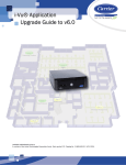
LonWorks Integration with the i-Vu Link
You can integrate LonWorks devices into an i-Vu CCN system with a i-Vu Link acting as a master device.
Carrier
i-Vu Link
i-Vu Link
LonWorks port
S2
Module driver
drv_ivulink_lon_<latest version>.driver*
Read/write capability
Can read from and write to the third-party equipment
Third party points supported
500
Third party
Supported equipment
Any device that supports the LonWorks protocol using
SNVT's**
Network media type
EIA-232 to SLTA-10 network adapter
Quantity of devices you can
physically connect to the i-Vu Link
1 LonWorks network segment with up to 64 LonWorks
devices, daisy-chained
*The i-Vu Link driver supports LonWorks devices connected to Port S2 and BACnet or Modbus devices
connected on the Ethernet port simultaneously. The third party point count for the i-Vu Link is the total of the
2 ports.
** UNVT's are proprietary and not supported.
LonWorks
1
Before-you-begin checklist
Before-you-begin checklist
Assumptions
You know how to create custom equipment in ApplicationBuilder.
You know how to install, wire, set up, and download memory to the i-Vu Link.
The LonWorks network/devices have been commissioned by the third-party representative
using LonMaker.
Items to be installed at the job site
Item
Notes
i-Vu Link
LonWorks module driver
drv_ivulink_lon latest version>.driver.
Echelon® SLTA-10 Serial LonTalk®
Adapter
You need 1 adapter for each i-Vu Link that is
connected to a LonWorks network segment. Make
sure you order the model that matches your
network topology. See the Echelon website
(http://www.echelon.com) for your local Echelon
sales contact.
•
•
•
•
#73351 for FT-10 networks
#73352 for TP-78 networks
#73353 for TP-1250 networks
#73354 for RS-485 networks
Echelon® power supply (part# 78010)
EIA-232/RS-232 straight-through cable
with 9-pin connectors
and an S2-DB9 adapter (purchase S2DB9 from Carrier)
CAUTION!
You can damage the SLTA-10 if it does not have its
own isolated power supply.
To connect the i-Vu Link to its SLTA-10. You can
buy an EIA-232/RS-232 cable with connectors or
buy 4-conductor cable and wire your own
connections.
or
18-22 AWG, 4-conductor cable and a
DB9 male adapter
2
Custom equipment files and graphics
LonWorks
Before-you-begin checklist
Other items needed for the integration
Item
Notes
LonWorks Integration Tool
Install from the Tools CD.
Network variable information
(.xif file) for each type of LonWorks
device. For example, VAV Controller or
Fan Coil Controller.
Get from:
Device address information
(domain, index, subnet, and node
address)
Manual for each type of LonWorks
device
LonWorks
•
•
•
the third-party representative
www.lonmark.com
the LonWorks device. See Appendix B.
Get from:
•
•
•
the customer
the third-party representative
a .log file obtained from the LonWork's device.
See Appendix B.
Get from the third-party representative or the thirdparty website.
3
The integration process
The integration process
Follow the steps in this document to integrate one or more third party LonWorks devices into an i-Vu CCN
system using an i-Vu Link. To install and network the i-Vu Link, see the i-Vu Link Installation and Start-up
Guide.
1 Create custom equipment in ApplicationBuilder
1
Start ApplicationBuilder.
2
Select equipment type:
○
CCN Values Only - to read and write values on the CCN network and to display those points on a
graphic
○
Integration Values Only - to read and write values from the third party network and to display those
points on a graphic
○
CCN Link Integration - to share values from the third party network with the i-Vu Link on the CCN
network and to display those points on a graphic
3
Click Next.
4
Type a name for the custom equipment (i.e., Hot Water System).
NOTE The name must not exceed 21 characters!
5
Enable English or Metric units.
6
Choose engineering options for your application (Schedule and Setpoint, Runtime, etc..)
7
Click Next.
8
Add Elements to your application.
NOTE Elements are a collection of input/output points that perform a specific operation. The
input/output point that is reading or writing to the LonWorks network is called an integration point.
Integration points may be used in conjunction with CCN points to share data between the LonWorks
network and the CCN network.
The available Elements that you can add to your custom equipment in ApplicationBuilder are:
Point type
Used for
Read CCN Point
Reading an analog or binary value from the CCN network
In: CCN Values, Link Integration
Carrier Text Point
Reading Text value from a CCN device
In: CCN Values, Link Integration
Setpoint Write
Allows CCN setpoint value to be “edited” directly from
graphic
In: CCN Values, Link Integration
4
LonWorks
The integration process
Point type
Used for
Link Integration Point to
CCN Point
Reading an analog or binary value from the third party
device and then writing that value to the CCN network
In: Link Integration
Link CCN Passive Point to
Integration Point
Exposing an analog or binary value to the CCN network so
that it can be written to the third party network
In: Link Integration
Read Integration Point
Reading an analog or binary value from the third party
device
In: Read Integration, Link Integration
Link CCN Point to
Integration Point
Reading an analog or binary value from a CCN device and
then writing it to the third party network
In: Link Integration
Link Integration Point to
CCN Passive Point
Reading an analog or binary value from the third party
device and then exposing that value to the CCN network
In: Link Integration
Link BACnet variable to
CCN Point
Allows an analog or binary value from BACnet to write
that value to the CCN network
In: Link Integration
9
As you add Elements, enter the requested information for the integration or CCN points:
○
Display Text - the name of the point as it will appear in i-Vu CCN (i.e., Frequency)
○
Reference Base - the name that will be added to each point that makes up the Element, so that all
points have a unique identifier (i.e.,input_Freq, trendFreq, output_Freq) - this name must be unique
(do not copy and paste)
○
Input Address - enter the LonWorks or CCN address
Define the LonWorks or CCN address string using the syntax for each point in the list, as described
below:
○
Input Scaling - enter variables
NOTE Use Scaling when the value you are reading from the LonWorks or CCN device needs to be
scaled before showing the value on a graphic or trend. Scaling information can be found in the third
party points list.
Example: You have an integration point set up to read the motor temperature of a variable speed
drive. The third party points list shows that this value will be given in degrees C, but you want to
display it in degrees F on a graphic. Therefore, using the formula °F = 9/5(°C) + 32, the scaling/unit
conversion fields for the integration point would be filled out as follows: ([value read] + 0) x 1.8 +
32
○
Output Address - enter the LonWorks or CCN address, as described below.
○
Output Scaling - enter variables
Continuing the example above, if you wanted the graphic to display values in °F, but then you
wanted to share that value with the CCN network in °C, the scaling for the CCN Passive Point would
be:
([value read] + 0) x1 + 0
LonWorks
5
The integration process
10 Click Next.
11 Equipment Name - type a new equipment name if desired.
12 Save Location - browse to a location where you would like to save the new custom equipment.
Click Save.
To format a LonWorks address
All Lonworks addresses should be assigned to "lonworks://" only when setting up address strings in
ApplicationBuilder. The LonWorks Integration Tool is used to define these addresses.
To format a CCN address
There are three different methods for defining the CCN address strings.
1
They can be manually typed in ApplicationBuilder.
2
You can use Copy table point in i-Vu CCN's table interface to copy CCN point information directly from a
CCN table to ApplicationBuilder's "ccn://" address field.
3
You can use Map to Point in i-Vu CCN's table interface to map the CCN points from your custom
equipment file directly to CCN table data.
NOTE Your custom equipment must already be downloaded in the i-Vu Link to use this method. (Proceed
to Assign and download custom equipment in i-Vu CCN first).
Method 1: Type the address manually in ApplicationBuilder
1
If you are actively reading or writing a point on a CCN device, then manually type in the CCN device's
address, Table Name, and Point Name that you wish to read or write.
ccn://link/<Table Name>/<Point Name> ("link" indicates the CCN device that the custom equipment
has been mapped to)
or
ccn://<bus, element>/<Table Name>/<Point Name>
Examples:
ccn://link/HWP01-32/TEMP
ccn://0,2/HWP01-32/TEMP
2
If the point is a CCN passive point (i.e, it's just being exposed to the CCN network), then type:
ccn://passive/<point name>, where <point name> is the name that you have chosen for this CCN point.
Example: ccn://passive/freq
6
LonWorks
The integration process
Method 2: Copy table point in i-Vu CCN
1
Launch i-Vu CCN.
2
Select the desired equipment in the navigation tree.
3
Expand the tables underneath that equipment.
4
Find the specific table and point that you want to read or write.
5
Click Copy in the table interface.
6
Inside of ApplicationBiuilder, hit CTRL-V to copy the CCN address from the table to the "ccn://" address
field.
Method 3: Map to point in i-Vu CCN
1
Launch i-Vu CCN.
2
Select the desired equipment in the navigation tree.
3
Expand the tables underneath that equipment.
4
Find the specific table and point that you want to read or write.
5
In the table interface, navigate to the Map to Point column.
6
From the drop-down menu, select the point in the custom equipment that should be mapped.
7
Click OK.
2 Assign and download the Lonworks driver
LonWorks
1
In the navigation tree, right-click on the i-Vu Link and select Driver Properties.
2
Right-click on the Driver node and select Configure.
3
In the Driver Version drop-down menu, select drv_ivulink_lon <latest version>.
4
Click OK and the driver will be automatically downloaded.
7
The integration process
3 Assign and download custom equipment in i-Vu CCN
1
Open i-Vu CCN.
2
In the navigation tree, right-click the area where you want to place the custom equipment. Select Add
Equipment from the drop-down menu.
3
Make the following entries:
Field
Notes
Display Name
Type an equipment name (i.e. ABB Drive).
Associate with
If your i-Vu Link is connected to CCN devices:
○
Enable CCN Device and fill in the bus and element
number of the CCN device that this custom
equipment will be linked to.
NOTE This "association" is what allows you to use the
term "link" in CCN address strings for this custom
equipment rather than manually typing in the bus,
element number into each CCN address string.
If your i-Vu Open Link is NOT connected to CCN devices
(only LonWorks devices):
○
Equipment
Enable CCN Link and pick the i-Vu Link that is
physically connected to the LonWorks network.
Click Add.
Browse to the .equipment file that was generated in
ApplicationBuilder.
Click Continue.
When message appears "File uploaded successfully",
click Close.
4
If you have already created a custom equipment graphic for this third party device in ViewBuilder, you
can also add that graphic from this screen. Under Views, click Add and browse to your .view file. Click
Continue. When message appears File added successfully, click Close. The custom equipment should
now appear in the navigation tree.
5
Click Exit Setup and the custom equipment will be downloaded to the i-Vu Link.
4 Configure LonWorks points using LonWorks Integration tool
8
1
Log in to i-Vu CCN.
2
In the navigation tree, right-click on the custom equipment and click Configure.
3
Navigate to the Integration Points section at the bottom of the screen and click Export.
LonWorks
The integration process
4
Click Save.
5
Browse to a location on your PC to save the file. (The file will have a .erl extension.)
6
Start the LonWorks Integration Tool (Lonworks_Integration_Tool.jar).
7
Click
8
Follow the wizard's instructions to create your LonWorks addresses.
9
Click
to start the wizard
to save the file to your PC. (The file will be saved with a .erl extension.)
10 Return to i-Vu CCN.
11 In the navigation tree, right-click on the custom equipment and click Configure.
12 Navigate to Integration Points at the bottom of the screen and click Import.
13 Browse to the .erl file that you saved in the LonWorks Integration Tool.
14 Click Open and then Continue to upload the file.
15 Click Close. The LonWorks addresses are now set.
To edit an integration or CCN point address
You can edit an integration or CCN point address in the following places:
•
In ApplicationBuilder
•
In i-Vu CCN on the custom equipment's Properties page > Equipment tab
•
In i-Vu CCN on the custom equipment's Properties page> Network Points tab
•
In the LonWorks Integration Tool
5 Connect an SLTA-10 to each i-Vu Link on the LonWorks network
segment
CAUTION!
You will damage the SLTA-10 if it does not have its own isolated power supply. Do not share power with the iVu Link.
LonWorks
1
Turn off the i-Vu Link’s power.
2
Remove power from the SLTA-10.
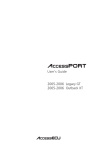
3
Set SLTA-10 DIP switches 1–8 as shown below. Switches 6–8 set the baud rate to 57600 for
communications between the control module and the SLTA-10 .
9
The integration process
4
Wire the i-Vu Link's Port S2 to the SLTA-10's EIA-232 port using one of the following methods:
○
If you have an EIA-232/RS-232 straight-through cable with connectors and an S2-DB9 Adapter:
Connect the adapter to the control module's port. Then connect one end of the cable to the adapter
and the other end to the SLTA-10's EIA-232 port.
○
If you have an 18-22 AWG, 4-conductor cable and a DB9 male adapter:
Wire one end of the cable to the control module's port and the other end to the adapter. See table
below. Then connect the adapter to the SLTA-10's EIA-232 port.
i-Vu Link's...
...to DB9
adapter pin
Tx
3
Rx
2
Signal Ground
5
5
Set the jumper for the control module's port to EIA-232.
6
Turn on the i-Vu Link's power.
7
Apply power to the SLTA-10.
6 Set up the driver properties
10
1
On i-Vu CCN's navigation tree, right-click on your custom equipment.
2
Select Driver Properties.
3
Expand Protocols and select LonWorks.
4
Select the i-Vu Link port S2 that connects to the SLTA-10.
5
In the Baud field, type 57600, the baud rate that you set on the SLTA-10 DIP switches.
6
Leave the default settings in the remaining fields under Port Configuration and the fields under
LonWorks Protocol Setup.
7
Under SLTA Domain Table, select Yes in the Define Domain Table field.
8
On the first line of the table (Index 0), enter appropriate values in each field. See table below.
9
In Windows Notepad, open the .log file that NodeUtil created. To see this file in the Open dialog box,
select All Documents in the Files of type field.
Field
Notes
Cloned
Select No for most applications.
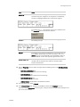
Domain Length
Locate this number in the .log file. The Domain Length is in the Size
field highlighted in the following example.
LonWorks
The integration process
Field
Notes
Domain ID
Locate this number in the .log file. The Domain ID is 1
2-character segment, 3 segments, or 6 segments. In the following
example, the highlighted Domain ID is 1 2-character segment.
In i-Vu CCN, type -00 after the ID as many times as needed so that
the Domain ID field has 6 2-character sections.
Subnet ID
Locate this number in the .log file. The Subnet ID is highlighted in
the following example.
Node ID
In this field, you are giving the SLTA/Router or Link an ID number on
the LonWorks network. Type any value in the range 1–127, but it
cannot be the same as the Node ID of any LonLonWorks device on
the LonLonWorks network. 99 is typically a good number to use.
Authentication Key
Do not change these values for most applications.
i-Vu CCN uses this authentication code if the third-party device
requests authentication.
10 Click the Properties button to refresh the page. Verify the following values in the SLTA Node Status
section:
○
SLTA Comm Established: Yes
(SLTA-10 and Carrier controller are communicating.)
○
SLTA Node Online: Yes
(SLTA-10 and LonWorks network are communicating.)
○
SLTA Node Configured: Yes
(SLTA-10 has been commissioned.)
○
Address Domain: (As displayed in the SLTA Domain Table)
11 On the navigation tree, select Protocols.
12 In the Protocol Status table, verify that the LonWorks protocol shows Running on port S2.
If the status shows Not running or the wrong port, verify port selection and DIP switch settings for that
port on the control module.
LonWorks
11
The integration process
7 Verify the control module is set up correctly
1
Verify that the latest custom equipment have been downloaded into i-Vu CCN.
2
On i-Vu CCN's navigation tree, select the custom equipment for the i-Vu Link.
3
On the Properties page, select the Network Points tab.
If...
Then...
You see the point value you
expect with no errors in the
Error column
You have successfully established communication with the thirdparty device.
A point shows question
marks instead of values
i-Vu CCN is not communicating with the i-Vu Link. Troubleshoot
communications. See the i-Vu Link's Installation Guide.
The point name is red
•
Check for typos in the microblock address.
•
Increase the Transaction Timer on the LonWorks Properties
page.
A value is incorrect
Verify that:
•
The Address in the integration point is correct.
•
The retrieved value is scaled properly, if necessary. For
example, scaled from Celsius to Fahrenheit.Refer to the thirdparty manufacturer's documentation for scaling information.
If the above solutions do not resolve the problem, gather the following information for technical support:
•
•
•
A diagnostic capture. See To get a diagnostic capture below.
A screenshot of the Driver Properties - right-click on the custom equipment in the navigation tree> select
Driver Properties > Properties page and the LonWorks > Properties page
A screenshot of the custom equipment's Properties page > Network Points tab showing addresses and
errors
To get a diagnostic capture
Use HyperTerminal, installed with Windows operating systems, to capture the communication between the iVu Link and the third-party device into a text file.
PREREQUISITES
•
The i-Vu Link's IP address
•
The longest integration point refresh time in the control program that has the error you are
troubleshooting. In i-Vu CCN, view the control program's Properties page > Network Points tab to see all
the refresh times.
1
Connect your computer's Ethernet port to the i-Vu Link's Ethernet port using one of the following:
2
12
○
A CAT5 or higher Ethernet crossover cable
○
A hub and a CAT5 or higher Ethernet straight-through cable
Ping the i-Vu Link to verify communications between the i-Vu Link and the computer you are using to get
this capture.
LonWorks
The integration process
3
On i-Vu CCN's navigation tree, right-click on custom equipment, select Driver Properties and then select
Protocols.
4
Click Properties, select Enable Telnet diagnostics, then click Accept.
5
From the desktop, select Start > Programs > Accessories > Communications > HyperTerminal.
6
Type any name for your connection, then click OK.
7
In the Connect using field, select TCP/IP (Winsock).
8
In the Host address field, type the IP address of the i-Vu Link, then click OK. Verify that Login:> appears
in the window.
9
On the menu, select File > Properties. On the Settings tab, click ASCII Setup, select Send line ends with
line feeds and Echo typed characters locally, then click OK twice.
10 Select Transfer > Capture Text, type the file path and name of the text file you are creating, then click
Start.
11 Restart the i-Vu Link using the restartmodule manual command or the i-Vu Link's power switch.
12 After Login:>, type:
diagport
Click Enter.
13 To capture data receipts, after diagport>:
• Type: lonworks rx
• Type: lonworks rx
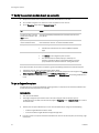
14 Verify the displayed text shows:
lonworks reporting level status:
rx on
tx on
app off
hi off
ldv off
off
off
off
If rx or tx, show "off", repeat step 14.
15 After diagport>, type:
go
Click Enter.
16 Run the capture for one of the following periods of time:
○
If all integration point refresh times are one minute or less, run the capture for 5 minutes.
○
If any integration point refresh time is longer than 1 minute, run the capture for 5 times the longest
microblock refresh time.
17 Type: stop
Click Enter. Verify that you see diagport> before doing the next step.
18 From the menu, select Transfer > Capture Text > Stop.
19 After diagport>, type:
logout
Click Enter.
20 From the menu, select File > Exit. Save the connection if you want to use the connection later with the
same settings.
21 In i-Vu CCN, clear the Enable Telnet diagnostics checkbox (see step 3 and 4), then click Accept.
22 Open the text file you defined in step 10, and verify that it legibly shows the same information that
HyperTerminal displayed.
LonWorks
13
Appendix B - Common HVAC SNVT's
Appendix B - Common HVAC SNVT's
SNVT #
SNVT Name
Element #
Measurement
Value
39
83
SNVT_temp
SNVT_state
0
0
°C
84
SNVT_time_stamp
0
1
year
month
2
day
3
hour
-274 — 6,279.5
0 — 65,535
Each bit must be parsed out using control program
logic.
0 — 3,000
1 — 12 = January — December
0 = month not specified
1 — 31
0 = day not specified
0 — 23
4
minute
0 — 59
5
second
0 — 59
0
1
zero offset
span multiplier
-163.84% — 163.835%
0 — 32.7675
85
SNVT_zerospan
87
SNVT_elapsed_tm
88
14
SNVT_alarm
0
day
0 — 65,535
1
hour
0 — 23
2
minute
0 — 59
3
second
0 — 59
4
millisecond
0 — 999
0—5
location
6
object ID (in node)
0 — 255 (decimal ASCII value)
location of node number,
description of characters used
0 — 65,535
LonWorks
Appendix B - Common HVAC SNVT's
SNVT #
LonWorks
SNVT Name
Element #
Measurement
Value
7
alarm type
8
priority level
9
index of NV in alarm
-13 = Alarm header
-12 = Alarm footer
-11 = Alarm debug
-10 = Alarm info
-6 = Alarm system info
-5 = Alarm value invalid
-4 = Alarm constant
-3 = Alarm offline
-2 = Alarm unknown
-1 = Value not available
0 = No alarm condition present
1 = Unspecified alarm condition present
2 = Total/service interval alarm 1
3 = Total/service interval alarm 2
4 = Total/service interval alarm 3
5 = Alarm low limit alarm clear 1
6 = Alarm low limit alarm clear 2
7 = Alarm high limit alarm clear 1
8 = Alarm high limit alarm clear 2
9 = Alarm low limit alarm 1
10 = Alarm low limit alarm 2
11 = Alarm high limit alarm 1
12 = Alarm high limit alarm 2
13 = Fire Alarm Condition
14 = Fire Pre-alarm condition
15 = Fire Trouble (fault) condition
16 = Fire Supervisory condition
17 = Fire Alarm condition in Test Mode
18 = Fire Pre-Alarm condition in Test Mode
19 = Fire Maximum environmental
compensation level reached
20 = Fire Abnormal condition with an input
object
21 = Fire Maintenance Alert
30 = Alarm fatal error
31 = Alarm error
32 = Alarm warning
0 (lowest priority) — 3 (highest priority)
LONMARK Fire products use the following:
4 = Life Safety Fire Alarms
(BACnet Priority 2)
5 = Property Safety Fire Alarms
(BACnet Priority 3)
6 = Fire Supervisory Alarm
(BACnet Priority 4)
7 = Fire Trouble/Fault (Display)
(BACnet Priority 5)
8 = Fire Pre-Alarm, HVAC Critical
Equipment Alarm
(BACnet Priority 6)
9 = HVAC Alarms
(BACnet Priority 8)
10 = HVAC Critical Equipment RTN, Fire
RTN (Display)
(BACnet Priority 10)
11 = HVAC RTN (lowest priority)
(BACnet Priority 16)
-1 = Value not Available
0 — 65,535
10 — 13
values of index
0 — 255, 0=not specified
14
year
0 — 3,000, 0=not specified
15
month
0 — 12, 0=not specified
16
day
0 — 31, 0=not specified
17
hour
0 — 23, 0=not specified
15
Appendix B - Common HVAC SNVT's
SNVT #
95
SNVT Name
SNVT_switch
Element #
Measurement
Value
18
minute
0 — 59, 0=not specified
18
second
0 — 59, 0=not specified
20
millisecond
0 — 999, 0=not specified
21 — 24
alarm_limit
0 — 255, 0=not specified
0
value
0 — 100%
1
state
enumerated
103
SNVT_hvac_emerg
0
106
SNVT_temp_setpt
0
°C occupied cool
0 = off,
1 = on,
–1 = undefined
0 = normal
1 = emergency pressurize
2 = emergency depressurize
3 = emergency purge
4 = emergency shutdown
5 = emergency fire
-273.17 — 327.66
1
°C standby cool
-273.17 — 327.66
2
°C unoccupied cool
-273.17 — 327.66
3
°C occupied heat
-273.17 — 327.66
4
°C standby heat
-273.17 — 327.66
5
°C unoccupied heat
-273.17 — 327.66
108
SNVT_hvac_mode
0
enumerated
109
SNVT_occupancy
0
status
0 = auto
1 = heat
2 = morning warmup
3 = cool
4 = night purge
5 = pre cool
6 = off
7 = test
8 = emerg heat
9 = fan only
10 = free cooling
11 = ice
12 = max heat
13 = economy
14 = dehumidify
15 = calibrate
16 = emerg cool
17 = emerg steam
18 = max cool
19 = hvac load
20 = no load
0 = oc–occupied
1 = oc–unoccupied
2 = oc–bypass
3 = oc–standby
oc–nul 0xFF
16
LonWorks
Appendix B - Common HVAC SNVT's
SNVT #
SNVT Name
Element #
Measurement
Value
111
SNVT_hvac_overid
0
state
0 = Not overridden
-1 = Value not available
The next 16 override values apply to all devices or
groups.
1 = Override position percentage - use
percent field
2 = Override flow in liters/sec - use flow
field
3 = Override flow percentage - use
percent field
4 = Override to position = 100%
5 = Override to position = 0%
6 = Override to configured minimum
7 = Override to configured maximum
8–16 = Unused
The next 16 override values apply to the first device or
group.
17 = Override position percentage - use
percent field
18 = Override flow in liters/sec - use flow
field
19 = Override flow percentage - use
percent field
20 = Override to position = 100%
21 = Override to position = 0%
22 = Override to configured minimum
23 = Override to configured maximum
24–32 = Unused
The next 16 override values apply to the second device
or group.
33 = Override position percentage - use
percent field
34 = Override flow in liters/sec - use flow
field
35 = Override flow percentage - use
percent field
36 = Override to position = 100%
37 = Override to position = 0%
38 = Override to configured minimum
39 = verride to configured maximum
40–48 = Unused
LonWorks
1
Percent of full scale
-163.83 — 163.83%
2
liters/second (flow)
0 — 65,534
17
Appendix B - Common HVAC SNVT's
SNVT #
SNVT Name
Element #
Measurement
Value
112
SNVT_hvac_status
0
mode
1
% primary heat output
0 = Controller automatically changes between
application modes
1 = Heating only
2 = Application-specific morning warm-up
3 = Cooling only
4 = Application-specific night purge
5 = Application-specific pre-cool
6 = Controller not controlling outputs
7 = Equipment being tested
8 = Emergency heat mode (heat pump)
9 = Air not conditioned, fan turned on
10 = Cooling with compressor not running
11 = Ice-making mode
12 = Max Heat
13 = Economy
14 = Dehumid
15 = Calibrate
16 = Emergency Cool
17 = Emergency Steam
18 = Max Cool
19 = HVC Load
20 = No Load
-1 = Value not available
-163.84% — 163.83
2
% secondary heat output
-163.84% — 163.83
3
% cool output
-163.84% — 163.83
4
% econ output
-163.84% — 163.83
5
% fan output
-163.84% — 163.83
6
% in alarm
0 — 255
113
SNVT_press_p
0
Pa(Pascal)
-32,768 — 32,768
127
SNVT_chlr_status
0
chiller run mode
0=
1=
2=
3=
1
chiller operation mode
2
chiller state
3
18
Overwrite this scene with new data
Delete this scene from the list
Display this sceneís data
Report the number of programmed
scenes
4 = Report the number of free scene
storage spaces
-1 = Value not available
0 = Controller automatically changes modes
1 = Heating only
2 = Morning warm-up
3 = Cooling only
4 = Night purge
5 = Pre-cool
6 = Controller not controlling outputs
7 = Equipment being tested
8 = Emergency heat pump
9 = Air not conditioned, fan turned on
10 = Cooling with compressor not running
11 = Ice-making mode
12 = Max Heat
13 = Economy
14 = Dehumidify
15 = Calibrate
16 = Emergency Cool
17 = Emergency Steam
18 = Max Cool
19 = HVC Load
20 = No Load
-1 = Value not available
1 = in alarm
1 = run is enabled
LonWorks
Appendix B - Common HVAC SNVT's
SNVT #
SNVT Name
Element #
Measurement
Value
4
1 = local
5
1 = limited
6
1 = chilled water flow
7
1 = conditioned water flow
2
Minutes to next state
0 = Area is occupied
1 = Area is unoccupied
2 = Area is temporarily occupied for the
bypass period
3 = Area is temporarily unoccupied
-1 = Value not available
0 = Area is occupied
1 = Area is unoccupied
2 = Area is temporarily occupied for the
bypass period
3 = Area is temporarily unoccupied
-1 = Value not available
0 — 65,535
138
SNVT_Volt_ac
0
Volt
0 — 65,535
139
SNVT_amp_ac
0
Amp
0 — 65,535
145
SNVT_hvac_type
0
enumerated
153
SNVT_Enthalpy
0
J/Kg
0 = Generic
1 = Fan coil
2 = VAV Terminal
3 = Heat Pump
4 = Roof Top Unit
5 = Unit Ventilator
6 = Chilled ceiling
7 = Radiator
8 = Air Handling Unit
9 = Self-contained unit
-32,768 — 32,767
128
LonWorks
SNVT_tod_event
0
current scheduled
occupancy state
1
next scheduled
occupancy state
19
Appendix B - Obtain network, device, and network variable information
Appendix B - Obtain network, device, and network variable information
Use one of the following devices to temporarily connect a LAPTOP to the LonWorks network.
•
•
•
Option 1: Using an Echelon U10/U20 Network Interface (page 20)
Option 2: Using an SLTA-10 Network Adapter (page 21)
Option 3: Using an iLonTM10 Ethernet Adapter (page 23)
PREREQUISITES
•
One of the above Echelon devices
•
The location of each LonWorks device's service pin from the third-party representative.
TIP For some VAV devices, the connected sensor's override button may also function as a service pin.
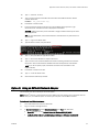
Option 1: Using an Echelon® U10/U20 USB Network Interface
To obtain and install Echelon software:
1.
Go to www.echelon.com/support/downloads.
2.
Log in or create a new login account.
3.
In Search for software in, select Network Interfaces, click Find, then download Open
LDV (latest version) Network Drivers for Windows 2000/XP/2003.
4.
In Search for software in, select Development Tools, click Find, then download NodeUtil
Node Utility (latest version).
5.
Run the Open LDV .exe file to install the software.
6.
Unzip the file that you downloaded for the NodeUtil Node Utility. Make note of this .exe
file's location.
EXAMPLE: c:\Lon stuff
To connect your computer to the LonWorks network:
7.
Connect the Echelon U10/U20 USB Network Interface to your computer's USB port and
to the LonWorks network segment.
8.
On the computer, select Start > Control Panel.
9.
Double-click LonWorks Interfaces.
10.
Select the USB tab, then write down the Network Interface Name.
EXAMPLE: LON2
To obtain the LonWorks device's .log file and .xif file:
20
11.
Select Start > All Programs > Accessories > Command Prompt.
12.
Type cd "<path>", replacing <path> with the path where you unzipped NodeUtil
(step 6 above), then press Enter.
EXAMPLE: cd "c:\Lon stuff"
13.
Type nodeutil -d<name>, replacing <name> with the Network Interface Name
noted in step 10 above, then press Enter.
EXAMPLE: nodeutil -dLON2
LonWorks
Appendix B - Obtain network, device, and network variable information
14.
Type O (the letter, not zero).
15.
Type a name for the file that NodeUtil will create with the LonWorks device's network
variable information.
EXAMPLE: vav_controller.log
16.
Press Enter to create the file.
17.
Push, then quickly release the service pin on the LonWorks device you want to get
information from. The device number is displayed in the window.
CAUTION Holding the service pin for 3 seconds or longer can delete memory from some
third-party devices.
TIP For some VAV devices, the connected sensor's override button may also function as
a service pin.
18.
Type G to go to the device menu.
19.
Type the device number, then press Enter.
20.
Type D, then press Enter for [all] domain tables.
21.
Type X, then wait for NodeUtil to request a file name.
22.
Type a name for the .xif file that NodeUtil will create containing the device and network
information. Omit the file extension; NodeUtil will automatically add the .xif extension.
NOTE If you do not specify a path, the file will be saved in the same folder as the
NodeUtil.exe file.
23.
Press Enter to create the .xif file.
24.
Type E to exit the device menu.
25.
Close the Command Prompt window.
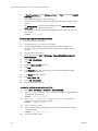
Option 2: Using an SLTA-10 Network Adapter
Your computer must have a serial port to use this option.
NOTE Echelon® software is incompatible with some USB to serial port adapters. If your computer does not
have a serial port, use a different option to connect your computer to the LonWorks network.
To obtain and install Echelon software:
LonWorks
1.
Go to www.echelon.com/support/downloads.
2.
Log in or create a new login account.
3.
In Search for software in, select Network Interfaces, click Find, then download
•
Open LDV (latest version) Network Drivers for Windows 2000/XP/2003
•
LonWorks SLTA-10 Serial LonTalk(R) Adapter Software for Windows 98/2000/XP
21
Appendix B - Obtain network, device, and network variable information
4.
In Search for software in, select Development Tools, click Find, then download NodeUtil
Node Utility (latest version).
5.
Run the Open LDV .exe file to install the software.
6.
Unzip the file that you downloaded for the LonWorks SLTA-10 Serial LonTalk(R) Adapter
Software.
7.
Run slta10_Win.exe to install the software. Make note of the numeric base for the
device name number. Typically, this number is 1.
8.
Unzip the file that you downloaded for the NodeUtil Node Utility. Make note of this .exe
file's location.
EXAMPLE: c:\Lon stuff
To connect your computer to the LonWorks network:
9.
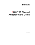
Remove power from the SLTA-10.
10.
Set DIP switches 1, 4, 6, 7, and 8 in the up position.
11.
Connect an EIA-232/RS232 straight-through cable to the SLTA-10 and to the
computer's serial port. The SLTA must also be connected to the LonWorks network
segment.
12.
Reapply power to the SLTA-10.
13.
On the computer, select Start > All Programs > Echelon SLTA-10 Network Adapter >
SLTALink Manager.
14.
Select Link > Select/Action.
15.
Click Edit.
16.
Select the Update Identifier checkbox.
17.
Click Next.
18.
In the Serial Port field, select the computer port that your EIA-232/RS232 straightthrough cable is connected to.
19.
In the Speed field, select 115200.
20.
Click Next > Finish > OK.
21.
Select Link > Connect Now.
22.
Minimize the SLTALink Manager.
To obtain the LonWorks device's .log file and .xif file:
22
23.
Select Start > All Programs > Accessories > Command Prompt.
24.
Type cd "<path>", replacing <path> with the path where you unzipped NodeUtil
(step 8 above), then press Enter.
EXAMPLE: cd "c:\Lon stuff"
25.
Type nodeutil -dlon<number>, replacing <number> with the number you
wrote down in step 7 above, then press Enter.
EXAMPLE: nodeutil -dLON1
26.
Type O (the letter, not zero).
27.
Type a name for the file that NodeUtil will create with the LonWorks device's network
variable information.
EXAMPLE: vav_controller.log
28.
Press Enter to create the file.
LonWorks
Appendix B - Obtain network, device, and network variable information
29.
Push, then quickly release the service pin on the LonWorks device you want to get
information from. The device number is displayed in the window.
CAUTION Holding the service pin for 3 seconds or longer can delete memory from some
third-party devices.
TIP For some VAV devices, the connected sensor's override button may also function as
a service pin.
30.
Type G to go to the device menu.
31.
Type the device number, then press Enter.
32.
Type D, then press Enter for [all] domain tables.
33.
Type X, then wait for NodeUtil to request a file name.
34.
Type a name for the .xif file that NodeUtil will create containing the device and network
information. Omit the file extension; NodeUtil will automatically add the .xif extension.
NOTE If you do not specify a path, the file will be saved in the same folder as the
NodeUtil.exe file.
35.
Press Enter to create the .xif file.
36.
Type E to exit the device menu.
37.
Close the Command Prompt window.
Close your connection
38
In the SLTA Link Manager, select Link > Disconnect Now, then close the window.
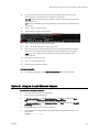
Option 3: Using an iLon10 Ethernet Adapter
To obtain and install Echelon software:
LonWorks
1.
Go to www.echelon.com/support/downloads.
2.
Log in or create a new login account.
3.
In Search for software in, select Network Interfaces, click Find, then download Open
LDV (latest version) Network Drivers for Windows 2000/XP/2003.
4.
In Search for software in, select Development Tools, click Find, then download NodeUtil
Node Utility (latest version).
5.
Run the Open LDV .exe file to install the software.
6.
Unzip the file that you downloaded for the NodeUtil Node Utility. Make note of this .exe
file's location.
EXAMPLE: c:\Lon stuff
23
Appendix B - Obtain network, device, and network variable information
To connect your computer to the LonWorks network:
7.
Connect your computer to the iLon10 using a crossover cable alone or a straightthrough cable with a hub. The iLon10 must also be connected to the LonWorks network
segment.
8.
On the computer, select Start > Control Panel.
9.
Double-click LonWorks Interfaces.
10.
Click Add.
11.
Type a name such as iLon10 and write down the name. You will use it later.
12.
Click Next twice.
13.
Type 1628 for the IP Port address of the iLon10.
NOTE 1628 is the default port and is used for most installations. If your computer does
not connect to the LonWorks network, ask the third-party representative if a different
port was used.
14.
Click Finish, then click Close.
To obtain the LonWorks device's .log file and .xif file:
15.
Select Start > All Programs > Accessories > Command Prompt.
16.
Type cd "<path>", replacing <path> with the path where you unzipped NodeUtil
(step 6 above), then press Enter.
EXAMPLE: cd "c:\Lon stuff"
17.
Type nodeutil -dx.default.<name>, replacing <name> with the name you
typed in step 11 above, then press Enter.
EXAMPLE: nodeutil -dx.default.iLon10
18.
Type O (the letter, not zero).
19.
Type a name for the file that NodeUtil will create with the LonWorks device's network
variable information.
EXAMPLE: vav_controller.log
20.
Press Enter to create the file.
21.
Push, then quickly release the service pin on the LonWorks device you want to get
information from. The device number is displayed in the window.
CAUTION Holding the service pin for 3 seconds or longer can delete memory from some
third-party devices.
TIP For some VAV devices, the connected sensor's override button may also function as
a service pin.
24
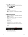
22.
Type G to go to the device menu.
23.
Type the device number, then press Enter.
24.
Type D, then press Enter for [all] domain tables.
25.
Type X, then wait for NodeUtil to request a file name.
LonWorks
Appendix B - Obtain network, device, and network variable information
26.
Type a name for the .xif file that NodeUtil will create containing the device and network
information. Omit the file extension; NodeUtil will automatically add the .xif extension.
NOTE If you do not specify a path, the file will be saved in the same folder as the
NodeUtil.exe file.
LonWorks
27.
Press Enter to create the .xif file.
28.
Type E to exit the device menu.
29.
Close the Command Prompt window.
25
CARRIER CORPORATION ©2010
A member of the United Technologies Corporation family · Stock symbol UTX · Catalog No. 11-808-401-01 · 4/21/2010