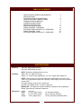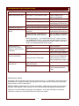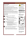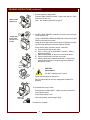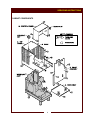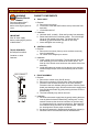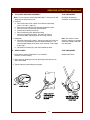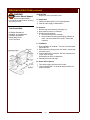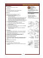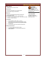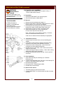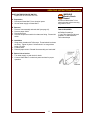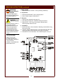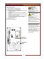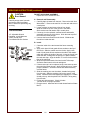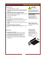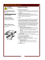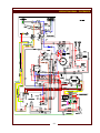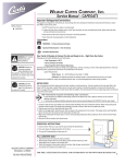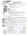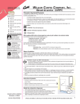
1
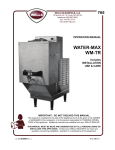
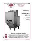
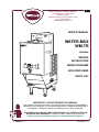
705
WELLS MANUFACTURING COMPANY
2 ERIK CIRCLE, P. O. Box 280
Verdi, NV 89439
Customer Service (775) 345-0444 Ext.502
fax: (775) 345-0569
www.wellsbloomfield.com
SERVICE MANUAL
WATER-MAX
WM-TR
Includes
SERVICE
INSTRUCTIONS
WIRING DIAGRAMS
EXPLODED VIEWS
PARTS LIST
IMPORTANT: DO NOT DISCARD THIS MANUAL
This manual is considered to be part of the appliance and is to be given to the OWNER or
MANAGER of the restaurant, or to the person responsible for TRAINING OPERATORS of
this appliance. Additional manuals are available from your WELLS DEALER.
THIS MANUAL MUST BE READ AND UNDERSTOOD BY ALL PERSONS USING OR
INSTALLING THIS APPLIANCE. Contact your WELLS DEALER if you have any
questions concerning installation, operation or maintenance of this equipment.
p/n 503364 Rev. A
S705
050705 cps
PRECAUTIONS AND GENERAL INFORMATION
WARNING:
Electric
Shock hazard
All servicing requiring
access to non-insulated
electrical components
must be performed by a
factory authorized
technician.
DO NOT open any access
panel which requires the
use of tools. Failure to
follow this warning can
result in severe electrical
shock.
CAUTION:
Risk of
Damage
DO NOT connect or
energize this appliance
until all installation
instructions are read and
followed. Damage to the
appliance will result if
these instructions are not
followed.
Water-Max™ hot water dispenser is intended for use in
commercial establishments only.
This dispenser is designed to dispense hot water used in the
preparation of food for human consumption. No other use is
recommended or authorized by the manufacturer or its agents.
Operators of this appliance must be familiar with the appliance use,
limitations and associated restrictions.
Operating instructions, warnings and labels must be read and
understood by all persons using or installing this appliance.
Cleanliness of this dispenser is essential to good sanitation. Read and
follow all included cleaning instructions and schedules to ensure the
safety of the food product.
Disconnect this appliance from electrical power before performing any
maintenance or servicing.
DO NOT submerge the dispenser or water tank in water. Do not
splash or pour water on, in or over any controls, control panel or wiring.
The technical content of this manual, including any wiring diagrams,
schematics, parts breakdown illustrations and/or adjustment
procedures, is intended for use by qualified technical personnel.
Any procedure which requires the use of tools must be performed by a
qualified technician.
This manual is considered to be a permanent part of the appliance.
This manual and all supplied instructions, diagrams, schematics, parts
breakdown illustrations, notices and labels must remain with the
appliance if it is sold or moved to another location.
This appliance is made in the USA. Unless otherwise noted, this
appliance has American sizes on all hardware.
xi
TABLE OF CONTENTS
PRECAUTIONS & GENERAL INFORMATION
SPECIFICATIONS
TROUBLESHOOTING SUGGESTIONS
SAFETY FEATURES & ERROR CODES
TEMPERATURE CALIBRATION
CLEANING INSTRUCTIONS
DELIMING INSTRUCTIONS
SERVICING INSTRUCTIONS
WIRING DIAGRAM - DISPENSER
EXPLODED VIEWS & PARTS LIST - DISPENSER
WIRING DIAGRAM - TANK
EXPLODED VIEWS & PARTS LIST - DISPENSER
xi
1
2
3
4
5
8
9
23
24
25
26
SPECIFICATIONS
Electrical:
208 Volts, Single Phase 35 Amps
240 Volts, Single Phase 35 Amps
NOTE: Requires a dedicated 50 Amp circuit
Plumbing:
Water Inlet: 1/4” Male Flare Fitting
Supply: 1/4” Female Flare supplied by a 1/4” O.D. or larger water supply line
NOTE: If water supply run from main supply line to Water-Max™ exceeds 12 feet,
a 3/8” O.D. or larger water supply line is required. Water supply line must be rated for
at least 180ºF.
For higher capacity, hook-up to a hot water line.
DO NOT use a saddle valve to connect to supply line.
IMPORTANT: This dispenser must be installed in compliance with all applicable
federal, state and local codes and ordinances.
Dimensions:
Height:
Width:
Depth:
Weight:
28-11/16”
10-1/16” (without tank)
22-7/16” (without tank)
74 lbs. (without tank)
1
15” (with tank installed)
25-1/4” (with tank installed)
150 lbs. (with tank installed and filled)
TROUBLESHOOTING SUGGESTIONS
SYMPTOM
POSSIBLE CAUSE
SUGGESTED REMEDY
POWER INDICATOR not lit
Water-Max™ not connected to power
Check POWER PLUG
Check circuit breaker
POWER switch OFF
Press POWER switch to ON
Insufficient water supply
Check water supply turned ON
And supplying at least 25 p.s.i.
Water tank not installed
Check tank for proper installation
TANK INDICATOR not lit
Tank not properly seated in receptacle
Check tank for proper installation
STATUS INDICATOR
flashing
ERROR detected - water pressure
insufficient
Check water supply turned ON
And supplying at least 25 p.s.i.
ERROR detected - temperature rise
between inlet and outlet insufficient
Be sure voltage is maintained
during all phases of operation
RESET Water-Max™: Turn POWER SWITCH OFF. Wait 20 seconds.
Turn POWER SWITCH ON. If unit resets and status indicator comes on
without flashing, error was (probably) a low water condition. Otherwise,
contact your Authorized Wells Service Agency.
No water flow from
dispense nozzle (power
indicator lit, status indicator
not flashing)
INDUCTIVE HEATER
operates intermittently
WATER TANK does not
keep water hot
Tank is full
Normal operation
Tank is sensed as full, but is actually
low
Clean water level probe
Replace probe if damaged
Tank not properly installed
Check tank for proper installation
Internal hi-limit tripping
Be sure all cooling openings
and louvers are unobstructed.
Cooling fan dirty or obstructed)
Clean cooling fan. Refer to
Servicing Instructions, page 14
Tank not properly installed (TANK
INDICATOR not lit)
Check tank for proper installation
Internal damage
Tank receptacle pins L1 to L2
should read approximately
144Ω
OPERATIONAL NOTES
Water-Max™ will not operate if water pressure is less than 25 p.s.i. If Water-Max™ shuts down (status
light flashes) for no apparent reason, other equipment on the water line may be reducing overall water
pressure and/or volume to Water-Max™.
ERROR CODES are displayed on the control board readout, visible through the view port on the upper
right side of the dispenser. Refer to page 3 for error code meanings and suggested remedial action.
There are no user serviceable components in the appliance. In all cases of damage or component
malfunction, contact your Authorized Wells Service Agency for repairs.
2
SAFETY FEATURES & ERROR CODES
SAFETY FEATURES
CAUTION:
Water-Max™ will not flow water from the dispense nozzle unless the
water tank is in place.
SHOCK HAZARD
Water-Max™ will not dispense into a full water tank.
The water tank heater will not heat unless the connector on WaterMax™ is fully mated with the tank receptacle. The heater on the water
tank is protected by an over-temp safety switch which will disable the
heater if the tank is allowed to run dry.
Water-Max™ cannot be energized (green power light will not be lit)
unless sufficient inlet water pressure is sensed.
Water-Max™ will go into error mode unless sufficient temperature rise
is sensed between inlet and output water while in the heating mode.
Water-Max™ will go into error mode and stop dispensing after approximately
96 minutes of continuous operation (i.e. 96 minutes without sensing a
“tank full” condition).
Removal of the top, front or
side panels results in
exposed electrical circuits.
Any procedure requiring the
removal of a panel must be
performed by a qualified
technician only.
NOTE: There is a 5 second
delay between the time the
power switch is turned on and
the time Water-Max™ begins
operation.
NOTE: Error codes are
displayed on the control
circuit board readout.
ERROR CODES
Open or disconnected INPUT TEMPERATURE
thermocouple.
→
Check connections at control board.
→
Check continuity of input temperature probe*.
WATER
PROBE
TANK
COMMON
WATER INPUT (+)
TS YEL
(-)
RED
Open or disconnected OUTPUT WATER TEMPERATURE
thermocouple.
→
Check connections at control board.
→
Check continuity of output temperature probe*.
Insufficient WATER TEMPERATURE RISE.
Must exceed 14ºF rise in 20 seconds.
→
Verify input water pressure does not exceed 40 p.s.i.
→
Verify input voltage. Delime unit.
→
Check resistance for both thermocouples (2-5 Ω),
plus thermocouple leads to heater (0-2 Ω).
A shorted thermocouple, or one detached from the
heater, will cause an error 4*.
Flow time exceeds 96 minutes of uninterrupted operation. Turn
power off. Wait 20 seconds, turn power back on.
* A short or loss of continuity in either input or output
thermocouple requires replacement of the inductive heater
assembly. Field repair of the heater is not recommended.
FILL
PROBE
TYPE K
(+)
YEL
(-)
RED
READOUT
(Error Code)
G2
A2
SCR
MODULE
TEMP
OFFSET
G1
TWL-T-1699-240
INPUT VOLTAGE: REV.
187-264VAC 60HZ
74869 REV.
WELLS/BLOOMFIELD
A1
L1
L2
SOL A
SOL B
SHUT-DOWN
To reset an error code,
correct the cause of the error,
then press the power switch
to OFF. After 20 seconds,
turn the power switch back
ON.
NOTE: Initial startup may
require multiple resets of
code 4 condition.
3
CALIBRATING TEMPERATURE
CAUTION:
SHOCK HAZARD
Removal of the top, front or
side panels results in
exposed electrical circuits.
Setting the temperature must
be performed by a qualified
technician only.
Use care whenever working
around exposed electrical
circuits.
Remove TOP PANEL. Insert the thermocouple of a digital thermometer
at least 4” into DISPENSER NOZZLE.
Install WATER TANK under DISPENSER NOZZLE. Press POWER
SWITCH to ON.
Run and discard at least one full tank of hot water to allow dispenser
temperatures to stabilize.
Temperature is factory set for 202ºF. Turn TEMP OFFSET on the
CONTROL CIRCUIT BOARD so that temperature on digital
thermometer reads 202ºF.
Press POWER SWITCH to OFF.
Upon completion of temperature adjustment, properly reinstall all
panels.
TANK GROUND
GREEN
TANK WATER
LEVEL PROBE
ORANGE
WATER
PROBE
STATUS
INDICATOR
LED
TANK
COMMON
FILL
PROBE
YELLOW
WATER INPUT (+)
TS YEL
(-)
RED
RED
YELLOW
INLET WATER
TEMPERATURE
SENSOR
RED
TYPE K
YELLOW
(+)
YEL
(-)
RED
SCR GATE 2
22 WHITE
G2
SCR A2
A2
SCR GATE 1
G1
24 BLACK
27 ORANGE
SCR A1
RED
OUTLET WATER
TEMPERATURE
SENSOR
READOUT
(Error Code)
SCR
MODULE
TEMP
OFFSET
CALIBRATE
TEMP
TWL-T-1699-240
INPUT VOLTAGE: REV.
187-264VAC 60HZ
74869 REV.
WELLS/BLOOMFIELD
A1
23 BROWN
E-MAX™ WM-TR
CONTROLLER
L1
15 BLACK
L2
21 RED
POWER
SOL A
SOL B
SHUT-DOWN
23 WHITE 24 BROWN 21 RED
INLET VALVES
BLUE
CONTACTOR
Fig. 7 Control Board
BOILING
POINT OF
WATER
210
TEMP. (ºF)
NOTE:
Refer to Table 1 below.
The practical maximum
temperature is the local
boiling temperature (based
on the altitude of the
installation) minus 10ºF.
If the stream is “sputtering”,
water temperature is set too
high, allowing steam to form
in the water flow. Set TEMP
OFFSET lower to
compensate.
205
200
195
190
0
0
0
0
0 00 0
0
0
0
0
00 00 00
50 1,0 1,5 2,0 2,50 ,00 ,50 ,00 ,50 ,00 ,50 6,0 ,50
3
5
4
5
4
6
3
ELEVATION (feet above seal level)
Table 1 Boiling Point of Water at Different Altitudes
4
MAXIMUM SAFE
TEMPERATURE
SETTING
CLEANING INSTRUCTIONS
DAILY CLEANING
CAUTION:
PRECAUTIONS:
Press POWER SWITCH to OFF (0).
Drain all water from TANK.
Remove tank from Water-Max™.
FREQUENCY:
Minimum - Daily, or as required
TOOLS:
Soft Cloth, Soft Bristle Brush
BURN HAZARD
Water in tank is extremely
hot. Use care when draining
tank.
CAUTION:
HOT SURFACES
Exposed surfaces can be hot
to the touch and may cause
burns.
CAUTION:
EQUIPMENT
DAMAGE
DO NOT SUBMERGE TANK
IN WATER!
IMPORTANT:
DO NOT use bleach,
abrasive cleansers or
cleansers containing
chlorides.
Wipe down the exterior of the Water-Max™ with a soft damp cloth.
Use a soft bristle brush to remove any calcium or lime build-up on the
end of the dispensing nozzle. Wipe dispensing nozzle clean with a soft
damp cloth.
Remove TANK LID.
Wipe TANK FAUCET, interior and exterior of tank with a soft damp
cloth. DO NOT SUBMERGE TANK IN WATER!
Fill tank with cool, clean water. Check operation of faucet.
If the faucet leaks:
Drain tank
Disassemble faucet by unscrewing bonnet from faucet body.
Clean or repair faucet as necessary.
Reassemble bonnet on faucet body.
Reinstall TANK LID.
Drain any remaining water from tank and re-install on Water-Max™.
Press POWER SWITCH to ON (I) and test for proper operation.
Procedure is complete.
5
DELIMING INSTRUCTIONS
CAUTION
Burn Hazard
DELIMING INSTRUCTIONS
PRECAUTIONS: Water in tank is EXTREMELY HOT (over 200ºF)
Turn Water-Max™ OFF
Water in Water-Max™ is
EXTREMELY HOT
Drain water from tank before moving.
FREQUENCY:
Weekly, or as required when Water-Max™ will not
maintain water at preset temperature.
TOOLS:
LIMESHIELD™ Scale and Food Soil Inhibitor
Funnel, Solution Bottle
Scrub Pad (Standard Green)
1 Gallon or Larger Plastic Container (Pitcher)
1. Power switch is located on right side of Water-Max™ base.
OFF
Press POWER SWITCH to OFF.
Drain 1 GALLON of water from TANK.
2. Examine SOLUTION BOTTLE for serviceability. If it is cracked or
distorted, replace it with a new bottle.
IMPORTANT: Delime with LIMESHIELD™ Scale and Food Soil
Inhibitor ONLY!
1
GAL
CAUTION
!
HOT
MIX
4 OZ
HOT TAP
WATER
+
2 ½ OZ
LIMESHIELD™
A graduated scoop is provided in the Limeshield™ container.
Measure 1/2 cup (4 ounces) of hot tap water. Pour this into the
1 gallon container.
Measure 1/3 cup (2.5 ounces) of Limeshield™ and pour slowly into
the water in the 1 gallon container.
When foaming stops, swirl solution to insure the
Limeshield™ is completely dissolved.
Use the provided funnel to pour the solution into
the solution bottle.
Dispenser cap is chained to the top of
Water-Max™.
WAIT UNTIL
FOAMING STOPS
THEN SWIRL
UNTIL MIXED
USE FUNNEL
FILL BOTTLE
Screw quick-disconnect dispenser cap onto
solution bottle.
3. QUICK-DISCONNECT FITTING is located
on the left top of Water-Max™. Press the
latch until it “clicks” open.
Invert solution bottle. Insert bottle quickdisconnect fitting into Water-Max™ quickdisconnect fitting. Press solution bottle
down until the latch “clicks”, locking the
solution bottle in place.
6
INSERT
BOTTLE
DELIMING INSTRUCTIONS (continued)
SQUEEZE
4. Squeeze solution bottle and force deliming solution into WaterMax™
5. Press latch on tank quick-disconnect fitting until it “clicks” to release
the solution bottle. Lift solution bottle straight up.
Unscrew quick-disconnect cap allowing solution bottle to return to
shape.
Rinse solution bottle with warm tap water. Fill solution bottle
2/3 full of warm tap water and reattach quick-disconnect cap.
After 10 minutes, insert solution bottle in quick-disconnect fitting.
Push down on bottle until latch “clicks”. Squeeze bottle, rinsing
quick-disconnect fittings and forcing deliming solution in WaterMax™ into the tank.
Press latch on tank quick-disconnect fitting to release the solution
bottle. While pressing button, lift solution bottle straight up. Press
the valve on the solution bottle fitting to allow the bottle to return to
shape. Press the small plunger on the Water-Max™ quickdisconnect to release the latch. Wipe both quick-disconnect fittings
with a soft cloth.
The quick disconnect fittings are now ready for the next deliming
session.
WAIT
REMOVE
BOTTLE
WIPE
QUICKDISCONNECTS
10 MIN
RINSE
BOTTLE
THEN
FILL WITH
TAP WATER
REMOVE
BOTTLE
INSERT &
SQUEEZE
6. Press power switch to ON. Water-Max™ will dispense water and
any remaining deliming solution into tank.
ON
WAIT
When Water-Max™ stops dispensing, press power switch to OFF.
Allow Water-Max™ to set for I HOUR with deliming solution in
tank.
After I hour, drain pitchers of water from tank until tank is
empty.
1 HOUR
OFF
Pour all water and solution from tank into a sink or appropriate
container for disposal.
UNTIL
TANK
IS
EMPTY
7
DELIMING INSTRUCTIONS (continued)
7. Remove tank from Water-Max™
Remove TANK COVER from tank. Rinse cover and dry. Store
tank cover for later use.
Note: See Cleaning Instructions page 15.
REMOVE TANK
REMOVE LID
8. WATER LEVEL PROBE is located in the tank, in the back right
corner near the top.
SCRUB TANK
Using a STANDARD GREEN SCRUB PAD, clean all scale and
lime from the water level probe.
INSIDE TANK,
AROUND LIP &
PROBE
Using the scrub pad, clean all scale and lime deposits from the
lip of the tank opening and from the inside of the tank.
If tank comes clean, proceed to step 9; otherwise,
a) Fill tank half full with hot tap water.
b) Pour 1-1/4 cup (10 oz) Limeshield™ into tank. Allow to
dissolve completely.
c) When foaming stops, fill tank to rim with hot tap water.
d) Let the solution soak in the tank over night
e) After the soak period, carefully drain tank. Loosen scale
deposits with scrub pad. Remove large scale deposits
through top of tank.
RINSE
TWICE
9.
CAUTION:
Shock Hazard
DO NOT submerge tank in water.
Rinse tank thoroughly at least twice.
Pour all rinse water into a sink or appropriate container for
disposal.
10. Reinstall tank cover on tank.
Reinstall tank on Water-Max™. Make sure tank connector is
fully seated on shelf.
Press power switch to ON.
REINSTALL
LID & TANK
ON
After a short delay, tank will begin filling.
Procedure is complete
8
SERVICING INSTRUCTIONS
CABINET COMPONENTS
9
SERVICING INSTRUCTIONS (continued)
WARNING
Electric Shock
Hazard
Disconnect Water-Max™
from electrical power
before removing any panel or
cover.
IMPORTANT
Shut off water supply
before performing any service
to Water-Max™
CABINET COMPONENTS
A. TANK SHELF
1. Removal
a. Remove two screws (g).
b. Lift the front of the tank shelf until the rear lip clears the front
assembly.
c. Lift the tank shelf off.
2. Installation
a. Hold tank shelf vertically. Slide rear lip under front assembly.
b. Rotate tank shelf to the horizontal position. The left and right
lips go on the outside of the wrap. The flange with the
weldnuts (g) goes behind the front web of the wrap.
c. Insert and tighten two screws (g).
B. CONTROL COVER
TOOLS REQUIRED:
#2 Phillips Screwdriver
Container to hold
fasteners
DISCONNECT
1. Removal
a. Remove two screws (a) from top cover, and two screws (b)
from front assembly.
b. Lift control cover straight up to remove.
2. Installation
a. Lower control cover into position. The left and right lips of the
front assembly go on the outside of the control cover. The
front lip of the control cover hooks over the outside of the front
assembly.
b. Install and tighten two screws (a) into the top cover, and two
screws through the lips of the front assembly into the control
cover.
C. FRONT ASSEMBLY
1. Removal
a. Remove the control cover (See B. above).
b. Remove four screws (c) from the front of the front assembly.
c. Disconnect the electrical connector for the front assembly.
Disconnect the error indicator wiring connector from the power
board (see drawing at right). Disconnect the nozzle supply hose
from the inductive heater by gently working the hose off of the
barbed fitting.
d. The front assembly may now be removed.
POWER
BOARD
2. Installation
a. Reconnect the nozzle supply hose by gently working the hose
onto the inductive heater barbed fitting, making sure it is fully
seated. Reconnect the electrical connector for the front assy.
It is keyed and will only connect one direction. Reconnect the
error indicator wiring connector to the power board. Observe
the locating tab to ensure proper connection.
b. Set the front assembly in position and reinstall four screws (c).
c. Reinstall control cover and tank shelf as detailed above.
10
SERVICING INSTRUCTIONS (continued)
D. TOP COVER AND WRAP ASSEMBLY
TOOLS REQUIRED:
Note: For the purpose of servicing Water-Max™, the top cover and
wrap may be removed as a unit.
#2 Phillips Screwdriver
Container to hold fasteners
1. Removal
a. Remove the tank shelf, control cover and front assembly.
(see A., B. and C., page 10).
b. Remove four screws (d) from the area beneath the shelf.
c. Remove screw (f) from power board support.
d. Loosen three chassis screws (e).
e. Remove deliming quick disconnect fitting.
f. Work the wrap off of the frame. Be aware of wiring or
connectors which may hang-up in the cooling louvers.
2. Installation
a. Work the wrap over the frame. Gently work the hole in the top
cover over the threaded end of the cleanout assembly. The
recessed side flanges of the lower cover must be on the inside
of the wrap.
b. Reinstall four screws (d) in the area beneath the shelf.
E. HOSE CLAMPS
Note: Be careful to avoid
scraping, trapping or pinching
wires as the wrap is lowered
over the frame.
TOOLS REQUIRED:
1. Hose clamps used on Water-Max™ are reusable.
DO NOT cut hose clamps.
Needle Nose Pliers
2. Open clamp by twisting an ear until the fingers slide past one an
other and release.
3. Tighten clamp by squeezing ears together.
11
SERVICING INSTRUCTIONS (continued)
WARNING
Electric Shock Hazard
Disconnect Water-Max™
from electrical power before removing
any panel or cover.
CONTACTOR
Repair time not to exceed 0.5 hour
A. Preparation
1. Disconnect Water-Max™ from electrical power.
2. Shut off water supply to Water-Max™.
B. Removal
TOOLS REQUIRED:
#2 Phillips Screwdriver
Container to hold fasteners
Flat Blade Screwdriver
Needle Nose Pliers
11/32” Nut Driver
1. Remove top cover and wrap (see page 11)
2. Note position of wires on contactor.
3. Disconnect old contactor:
a. Disconnect wires from contactor.
b. Remove two self-locking nuts holding contactor to
shelf. Lift old contactor off of studs; discard old
contactor.
C. Installation
1. Note orientation of contactor. The two coil screws point
toward the left.
2. Slide contactor mounting holes over studs. Secure with
self-locking nuts.
3. Connect wires to the contactor. Be sure connectors for
12 ga. wires are tight.
See drawing at left for configuration.
4. Reinstall top cover and wrap.
D. Return Unit to Service
1. Turn water supply on and check for leaks.
2. Connect Water-Max™ to electrical power and test for
proper operation.
12
SERVICING INSTRUCTIONS (continued)
SCR ASSEMBLY
Repair time not to exceed 1.0 hour
WARNING
Electric Shock
Hazard
A. Preparation
Disconnect Water-Max™ from
electrical power before removing
any panel or cover.
1. Disconnect Water-Max™ from electrical power.
2. Shut off water supply to Water-Max™.
B. Removal
1. Remove top cover and wrap (see page 11)
2. Disconnect cleanout assembly:
a. Disconnect hose clamp on supply hose.
Remove supply hose.
b. Disconnect flare fitting from inductive heater inlet tube. Be
sure to use a 7/16” backup wrench on the cleanout tube
flare fitting. Avoid moving or stressing the inlet tube.
c. Remove the cleanout assembly by lifting the cleanout body
while guiding the tubing through the hole in the bracket.
3. Disconnect the contactor shelf:
a. Remove two nuts at the corners of the shelf.
b. Lift the shelf only enough to gain access to the SCR
heatsink screws.
4. Disconnect old SCR assembly:
a. Remove two screws from the bottom of the SCR heatsink.
b. Note position of wires on SCR.
c. Disconnect wires from SCR. Discard entire SCR and
heatsink assembly .
C. Installation
1. Note orientation of SCR assembly. The notch in the base of
the SCR faces the front of the unit. The fins of the heatsink
face the right (power switch) side.
2. Connect wires. See drawings at right for configuration.
3. Install two screws holding SCR assembly to shelf.
4. Reinstall contactor shelf to unit.
5. Reinstall cleanout assembly.
Be sure to use a backup wrench when attaching flare fitting to
the inlet tube of heater. Avoid moving or stressing the inlet
tube.
6. Reinstall top cover and wrap.
D. Return Unit to Service
1. Turn water supply on and check for leaks.
2. Connect Water-Max™ to electrical power and test for proper
operation.
13
TOOLS REQUIRED:
#2 Phillips Screwdriver
Container to hold fasteners
Needle Nose Pliers
7/16” & 9/16” Open End Wrenches
SERVICING INSTRUCTIONS (continued)
WARNING
Electric Shock
Hazard
Disconnect Water-Max™ from
electrical power before removing
any panel or cover.
COOLING FAN
Repair time not to exceed 1.0 hour
A. Preparation
1. Disconnect Water-Max™ from electrical power.
2. Shut off water supply to Water-Max™.
B. Removal
TOOLS REQUIRED:
#2 Phillips Screwdriver
Container to hold fasteners
Needle Nose Pliers
7/16” & 9/16” Open End Wrenches
1. Remove top cover and wrap (see page 11)
2. Disconnect cleanout assembly:
a. Disconnect hose clamp on supply hose.
Remove supply hose.
b. Disconnect flare fitting from inductive heater inlet tube.
Be sure to use a 7/16” backup wrench on the cleanout
tube flare fitting.
Avoid moving or stressing the inlet tube.
c. Remove the cleanout assembly by lifting the cleanout
body while guiding the tubing through the hole in the
bracket.
3. Disconnect the contactor shelf:
a. Remove two nuts at the corners of the shelf.
b. Lift the shelf only enough to gain access to the fan and
mounting screws.
4. Remove old fan:
a. Remove two screws holding fan to heater.
b. Disconnect wires. Discard old cooling fan.
C. Installation
1. Connect wires.
2. Attach new fan to heater.
3. Reinstall contactor shelf to unit.
4. Reinstall cleanout assembly. Be sure to use a backup
wrench when attaching flare fitting to the inlet tube of
heater. Avoid moving or stressing the inlet tube. Be
sure braided supply tubing is not kinked.
5. Reinstall top cover and wrap.
D. Return Unit to Service
1.
2.
Turn water supply on and check for leaks.
Connect Water-Max™ to electrical power and test for
proper operation.
14
SERVICING INSTRUCTIONS (continued)
POWER SWITCH
Repair time not to exceed 0.5 hour
WARNING
Electric Shock
Hazard
A. Preparation
Disconnect Water-Max™ from
electrical power before removing
any panel or cover.
1. Disconnect Water-Max™ from electrical power.
2. Shut off water supply to Water-Max™.
B. Removal
1.
2.
3.
4.
Remove front assembly and tank shelf (see page 10).
Remove paper shield.
Note position of wires on switch. Disconnect wires.
Compress mounting fingers on switch. Push switch from inside
to remove; discard old switch.
C. Installation
1.
2.
3.
4.
Note orientation of switch. ON ( I ) goes up.
Push switch through mounting hole until fingers engage
and the flange of the switch sits flush against the cabinet.
Reinstall wires.
Reinstall paper shield, front assembly and tank shelf.
D. Return Unit to Service
1.
2.
Turn water supply on and check for leaks.
Connect Water-Max™ to electrical power and test for
proper operation.
15
TOOLS REQUIRED:
#2 Phillips Screwdriver
Container to hold fasteners
Needle Nose Pliers
SERVICING INSTRUCTIONS (continued)
WARNING
Electric Shock
Hazard
INLET WATER VALVE ASSEMBLY
Repair time not to exceed 0.5 hour (replace valve), or
1.0 hour (clean strainer screen)
Disconnect Water-Max™ from
electrical power before removing
any panel or cover.
A. Preparation
TOOLS REQUIRED:
B. Removal
#2 Phillips Screwdriver
Container to hold fasteners
Needle Nose Pliers
2 ea. 5/8” Open End Wrenches
Brush (Toothbrush or similar)
1. Disconnect Water-Max™ from electrical power.
2. Shut off water supply to Water-Max™.
1. Remove top cover and wrap (see page 11).
2. Remove paper shield. Disconnect supply hoses from valves.
Refer to page 27 for removal of hose clamps.
3. Disconnect the inlet tubing flare fitting. Be sure to use a
backup 5/8” wrench on the bottom fitting of the valve.
4. Note position of wires on valves. Disconnect wires.
5. Slide valve assembly out of valve mounting clip.
Do not remove clip from frame bracket.
Note: Valve screen is removable for cleaning; otherwise,
valves are sealed and cannot be rebuilt.
Clean valve or discard old valve assembly as appropriate.
C. Clean Strainer Screen
1. Unscrew cap from end of valve, remove inlet fitting and
washer.
2. Using pliers, extract screen by grasping tab and working
screen from valve body. Note orientation of screen.
3. Clean screen under running water. Use a fine brush if
necessary to remove debris and build-up.
4. Reinstall screen in valve body. Note: tab on screen faces
away from valve body.
5. Check inlet fitting for debris or build-up. Clean under running
water using a fine brush if necessary.
6. Reinstall inlet fitting and washer into cap. Screw cap back
onto valve.
D. Valve Installation
1. Snap valve assembly into mounting clip. Dual barb
fittings point up.
2. Connect inlet tubing flare fitting. Be sure to use a backup 5/8”
wrench on the bottom fitting of the valve.
3. Reconnect supply tubes.
4. Reconnect wires. Reinstall paper shield.
5. Reinstall top cover and wrap.
E. Return Unit to Service
1. Turn water supply on and check for leaks.
2. Connect Water-Max™ to electrical power and test for proper
operation.
16
SERVICING INSTRUCTIONS (continued)
INLET WATER PRESSURE SWITCH
Repair time not to exceed 0.5 hour
WARNING
Electric Shock
Hazard
A. Preparation
Disconnect Water-Max™ from
electrical power before removing
any panel or cover.
1. Disconnect Water-Max™ from electrical power.
2. Shut off water supply to Water-Max™.
B. Removal
1.
2.
3.
4.
Remove front assembly and tank shelf (see page 10).
Remove paper shield.
Disconnect wires.
Unscrew old pressure switch from brass tee fitting. Discard old
switch.
C. Installation
1. Wrap switch threads with Teflon tape. Thread switch into brass
tee fitting. Tighten by hand. Switch should be snug without
being over-tight.
2. Connect wires.
3. Reinstall paper shield. Reinstall front assembly and tank shelf.
D. Return Unit to Service
1. Turn water supply on and check for leaks.
2. Connect Water-Max™ to electrical power and test for proper
operation.
17
TOOLS REQUIRED:
#2 Phillips Screwdriver
1” (very thin) Open End Wrench
Container to hold fasteners
Teflon thread tape
SERVICING INSTRUCTIONS (continued)
WARNING
Electric Shock
Hazard
Disconnect Water-Max™
from electrical power before
removing any panel or
cover.
CAUTION:
SHOCK HAZARD
Removal of the top, front or
side panels results in
Exposed electrical circuits.
Setting the temperature
must be performed by a
qualified technician only.
Use care whenever working
around exposed electrical
circuits.
POWER BOARD
Repair time not to exceed 1.0 hour (including calibration)
A. Preparation
1. Disconnect Water-Max™ from electrical power.
2. Shut off water supply to Water-Max™.
B. Removal
1. Remove front assembly (see page 10).
2. Note wiring connections. Disconnect wiring from board.
3. Remove 4 ea. 11/32” nuts from corners of power board.
Remove power board from unit.
C. Installation
1. Install new board. Note orientation. Mounting nuts should be snug,
but not over-tight.
2. Connect wires per drawing below. Be careful that inlet and outlet
water temperature thermocouples are properly connected.
3. Reinstall front cover assembly. Do not install support cover yet.
TOOLS REQUIRED:
Digital Thermometer
#2 Phillips Screwdriver
Small flat-blade screwdriver
11/32” Nut Driver
Container to hold fasteners
Needle Nose Pliers
18
SERVICING INSTRUCTIONS (continued)
D. Return Unit to Service
1. Turn water supply on and check for leaks.
2. Connect Water-Max™ to electrical power.
3. Calibrate power board. See drawing below.
a. Insert the thermocouple of a digital thermometer at least 4”
into dispenser nozzle.
b. Install water tank under dispense nozzle. Press power
switch ON.
c. Run and discard at least one full tank of hot water to allow
dispenser temperatures to stabilize.
d. Temperature is factory set for 201ºF. Turn temp offset on
the power board so that the temperature on digital
thermometer reads 201ºF.
4. Reinstall support cover.
5. Test unit for proper operation
WARNING
Electric Shock
Hazard
Disconnect Water-Max™ from
electrical power before removing
any panel or cover.
CAUTION: SHOCK
HAZARD
Removal of the top, front or side
panels results in
Exposed electrical circuits.
Setting the temperature must be
performed by a qualified technician
only.
Use care whenever working
around exposed electrical circuits.
NOTE: The practical maximum
temperature is the local boiling
temperature (based on the altitude
of the installation) minus 10ºF.
WATER
PROBE
TANK
COMMON
If the stream is “sputtering”, water
temperature is set too high,
allowing steam to form in the water
flow. Set TEMP OFFSET lower
to compensate.
FILL
PROBE
WATER INPUT (+)
TS YEL
(-)
RED
TYPE K
(+)
YEL
(-)
RED
READOUT
(Error Code)
G2
A2
SCR
MODULE
TEMP
OFFSET
G1
CALIBRATE
TEMP
TWL-T-1699-240
INPUT VOLTAGE: REV.
187-264VAC 60HZ
74869 REV.
WELLS/BLOOMFIELD
A1
L1
L2
SOL A
SOL B
SHUT-DOWN
19
SERVICING INSTRUCTIONS (continued)
CAUTION:
Burn Hazard
Carefully empty water from tank
and remove tank from WaterMax™ and before performing any
servicing.
TOOLS REQUIRED:
18” Adjustable Wrench
Container to hold fasteners
Teflon Thread Tape
Food-Grade Silicone Sealant
FAUCET AND SHANK ASSEMBLY
Repair time not to exceed 0.5 hour
A. Removal and Disassembly
1. Carefully drain all water from the tank. Remove the tank from
Water-Max™. Remove the tank lid from the tank and store in
a safe place.
2. Loosen retainer nut and remove faucet from shank.
Slide the retainer clip out of the groove in the shank.
Store retainer nut and retainer clip in a safe place.
3. If seat cup is to be replaced, unscrew bonnet and handle
assembly from the top of the faucet. Work the seat cup off of
the end of the faucet plunger.
4. Unscrew the faucet shank from the ferrule. Withdraw the
ferrule from inside the tank.
B. Install
1. Clean the inside of the tank around the faucet mounting
hole.
2. Apply a thin bead of food-grade silicone sealant to the lip of
the ferrule. Slide the washer onto the ferrule. Apply a thin
bead of food-grade silicone sealant to the side of the washer
which will contact the inside of the tank. Insert the ferrule from
inside the tank, making sure the spacer is in place between
the tank and wrap. Align the double ”D” on the ferrule with the
flats of the tank hole.
3. Wrap the exposed threads of the ferrule with Teflon tape.
Screw the shank onto the ferrule and tighten.
4. If faucet seat cup is to be replaced, snap a new seat cup onto
the end of the faucet plunger. Work the faucet lever to insure
proper installation. Screw the bonnet and handle assembly
onto the faucet.
5. Slide the retaining nut over the shank, threads facing away
from the tank. Slide the retaining clip into the groove in the
shank. Install the faucet and tighten the retaining nut. Handle
should point up, with the printed “HOT WATER” facing away
from the tank.
6. Fill the tank with tap water. Check for leaks.
Test the faucet for proper operation.
7. Empty the tank. Install the tank lid and reinstall tank on WaterMax™.
20
SERVICING INSTRUCTIONS (continued)
DISPENSER TANK
CAUTION:
Burn Hazard
A. Tank Disassembly (refer to page 27)
1. Carefully drain all water from the tank. Remove the tank from
Water-Max™. Remove the tank lid from the tank and store in
a safe place.
2. Remove temperature gauge and holding nut from tank.
3. Disassemble faucet shank assembly (see page 20).
4. Remove four screws (517) from side lips of reservoir assembly.
5. Lift tank reservoir assembly out of wrap.
6. Disconnect wiring as required.
B. Reassembly
1. Reconnect any wires disconnected during service.
2. Apply a thin bead of food-grade silicone sealant along the top
lip of the wrap.
3. Install tank reservoir into wrap. Be sure tank is properly
oriented.
4. Secure reservoir assembly into tank by installing four screws in
side lips.
5. Reinstall faucet assembly (see page 20).
6. Fill the tank with tap water. Check for leaks.
7. Empty the tank. Install the tank lid and reinstall tank on WaterMax™.
Carefully empty water from tank
and remove tank from WaterMax™ and before performing any
servicing.
TOOLS REQUIRED:
#2 Phillips Screwdriver
18” Adjustable Wrench
Container to hold fasteners
Teflon Thread Tape
Food-Grade Silicone Sealant
Note: Be careful to avoid
scraping, trapping or pinching
wires as the reservoir is lowered
into the wrap.
TOOLS REQUIRED:
TANK HEATER
1. Disassemble tank per above.
2. Using a putty knife or similar scraper, remove old heater
assembly and any remaining RTV from outside of tank.
3. Attach new heater assembly to bottom and front of tank.
Refer to Exploded View on page 27 for location.
4. Seal edges of heater using Hi-Temp (red) RTV sealant.
5. Allow to set for at least one hour, then reassemble tank as
detailed above.
21
#2 Phillips Screwdriver
18” Adjustable Wrench
Container to hold fasteners
Teflon Thread Tape
Food-Grade Silicone Sealant
Putty Knife
Hi-Temp (Red) RTV Sealant
SERVICING INSTRUCTIONS (continued)
CAUTION:
Burn Hazard
Carefully empty water from tank
and remove tank from WaterMax™ and before performing any
servicing.
TOOLS REQUIRED:
#2 Phillips Screwdriver
7/16” Open-End Wrench
Container to hold fasteners
Food-Grade Silicone Sealant
Note: Be careful to avoid
scraping, trapping or pinching
wires as the reservoir is lowered
into the wrap.
LOW WATER LEVEL PROBE
Repair time not to exceed 0.5 hour
A. Removal and Disassembly
1. Carefully drain all water from the tank. Remove the tank from
Water-Max™. Remove the tank lid from the tank and store in
a safe place.
2. Disassemble the tank (see page 21).
3. Disconnect wiring from the probe. Disassemble probe.
Withdraw the probe from the inside of the tank. Discard the
old probe and nylon sealing washers.
B. Install
1. Clean the inside of the tank around the probe mounting hole.
2. Apply a thin bead of food-grade silicone sealant around the
lip of the male sealing washer. Insert the male sealing
washer into the mounting hole from the inside of the tank.
3. Apply a thin bead of food-grade silicone sealant to one side of
the female sealing washer. From outside of the tank, slide the
female sealing washer over the protruding shoulder of the
male sealing washer with the sealant side toward the tank.
4. Install probe assembly:
a. Apply a thin bead of food-grade silicone sealant to the
underside of the head of the probe.
b. Insert the probe into the sealing washers from the inside
of the tank. Orient the slot in the face of the probe
vertically.
c. Slide a flat washer and a lock washer over the protruding
threads of the probe. Thread on one nut. Tighten until the
sealing washer assembly is visibly compressed.
5. Reconnect wiring.
6. Examine all wiring connectors. Be sure that all connectors are
secure before reassembling tank.
7. Reassemble tank (see page 21).
8. Fill the tank with tap water. Check for leaks.
9. Empty the tank. Reinstall tank on Water-Max™. Observe
operation as the tank fills:
a. Water-Max™ should dispense until the water level
reaches the probe.
b. Dispense must stop when the water level reaches the
probe.
10. Reinstall the tank lid.
22
WIRING DIAGRAM - DISPENSER
23
EXPLODED VIEW & PARTS LIST - DISPENSER
WATER-MAX™ DISPENSER
24
EXPLODED VIEW & PARTS LIST - DISPENSER (continued)
25
WIRING DIAGRAM - TANK
RECEPTACLE
WATER
LEVEL
PROBE
ORANGE
L2
BLACK
GREEN
L1
TANK
GND
HEATING
ELEMENT
(100W)
RED
OVER-TEMP SAFETY SWITCH
SCHEMATIC FOR 240V 400W 5 GAL TANK
EXPLODED VIEW & PARTS LIST - TANK
WATER-MAX™ 5 - GALLON WATER TANK
26
HEATING
ELEMENT
(300W)
EXPLODED VIEW & PARTS LIST - TANK (continued)
501
520
4 pl 517
504
519
518
508
512 2 pl
2 pl 514
510
513
505
4 pl 516
506
2 pl 509
515 4 pl
511
part of
item 507.
507
p/n 75013 Rev. A
27
WELLS MANUFACTURING COMPANY
DIVISION OF CARRIER REFRIGERATION
2 ERIK CIRCLE, P. O. Box 280
Verdi, NV 89439
Customer Service (775) 345-0444 Ext.502
fax: (775) 345-0569
www.wellsbloomfield.com