1
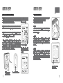
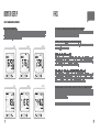
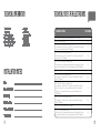
E2
WIRELESS
ELECTRICITY
MONITOR
FCC NOTE:
This device complies with Part 15 of the FCC Rules. Operation is subject to the following two conditions: (1) this device may not
cause harmful interference, and (2) this device must accept any interference received, including interference that may cause
undesired operation. The manufacturer is not responsible for any radio or TV interference caused by unauthorized modifications
to this equipment. Such modifications could void the user’s authority to operate the equipment.
IC NOTE:
This device complies with Industry Canada licence-exempt RSS standard(s). Operation is subject to the following two conditions:
(1) this device may not cause interference, and (2) this device must accept any interference, including interference that may cause
undesired operation of the device.
Under Industry Canada regulations, this radio transmitter may only operate using an antenna of a type and maximum (or lesser)
gain approved for the transmitter by Industry Canada.
To reduce potential radio interference to other users, the antenna type and its gain should be so chosen that the equivalent
isotropically radiated power (e.i.r.p.) is not more than that necessary for successful communication.
INSTRUCTION MANUAL
CONTENTS
INTRODUCTION
SAFETY
IN THE BOX
HARDWARE INSTALLATION
Prior to Installation
Mounting Individual or Multiple Circuits
Monitor Installation Considerations
Installing the CT Sensors
INTRODUCTION
2
3
5
6
7
9
10
MONITOR SETUP
Linking the Transmitter and Monitor
Setting the Time and Date
Setup Instructions
Dual Tariff Mode
How To Change Functions
How To Change Modes
11
12
13
15
17
18
FAQS
TECHNICAL INFORMATION
INSTALLATION NOTES
TECHNICAL NOTES FOR ELECTRICIAN
20
21
21
22
Energy metering and monitoring are at the heart of energy management, understanding when
and where your energy is consumed is key to saving money.
The e2 wireless electricity monitor shows the amount of energy that a household is consuming
at the time the display is read. The display can also give the user a reading showing usage in
financial terms. You can walk around the home with your monitor device, switching appliances
on and off, to see the difference that each one makes. With a few small changes in your
consumption behaviour the e2 can help you reduce your energy costs.
Ask Johnny
If you have any questions about using your efergy monitor or if you’d like further advice on
monitoring electricity at home, please feel free to contact us, or visit the website for up to date
information, downloads and frequently asked questions.
Email your questions to;
[email protected] for US
[email protected] for Canada
Email your technical questions to;
[email protected] for US and Canada
We aim to answer all your emails within 48 hours
www.efergy.us for US
www.efergycanada.ca for Canada
2
IMPORTANT SAFETY INFORMATION
It is important that you take some simple precautions before using this product. Incorrect use
or poor safety practices can result in injury or fatality. Whenever possible, turn off the main
breaker, outside your home feeding power to your electric panel.
When installing the efergy monitor you should find that everything is straight-forward. However,
there are a number of important health and safety issues which you need to be aware of:
• CT sensor clip fits onto the internal live feed cable inside the electricity meter, which delivers
the live supply to your home.
• Please read and act upon the important information on the following pages. Remember the
device is not intrusive and does not require rewiring; no wires or cables need to be cut, removed
or modified to perform this installation.
• efergy energy monitoring systems are considered plug and play devices that meet all
regulatory requirements for installation in Canada and the United States.
• In some countries (i.e Australia) the live cable can only be accessed by qualified electricians.
Do not force or bend the cables at any point during installation. If you are worried or have any
concerns about the installation, please contact a qualified electrician immediately.
The user does not need to remove the sensor throughout the working life of the unit. Battery
changes are performed on the transmitter and on the display. There are no batteries to change
in the sensor.
Even with the main breaker in the off position, the connection lugs where the main wires
terminate at the main breaker may still be live with potentially lethal voltage. Stay clear of these
connections during the installation of the CT sensors (Page 9 Fig. 1 & 2).
The CT sensors themselves are insulated so do not be concerned if they slide down the main
wire to the breaker after being secured around the insulated wire. A plastic tie wrap (with 2” of
the tie not cut off) secured to the main wire under the desired location for the CT sensor may
be used to keep the CT sensor from sliding down the wire.
Millions of these systems have been installed world wide without incident but please follow safe
work practices as outlined during the installation.
• If you notice anything unusual about the electricity supply such as loose wires, exposed cabling,
burn marks, holes in the insulating materials or damage to the electric wires in the service panel
or where the CT sensors are to be attached, stop immediately and report the findings to your
supply company.
3
4
IN THE BOX
HARDWARE INSTALLATION
PRIOR TO INSTALLATION
Your e2 Pack contains the following elements:
CT sensor
Transmitter
2 x XL CT Sensors
1 x Transmitter
1 x e2 Wireless Energy Monitor
3 x AA Batteries
3 x AAA Batteries
You will need to attach the sensor to the live
feed cable which connects the meter to the
monitor. Any power you use in your home will
pass through this cable. The clip on sensor acts
as a CT sensor, and relays the amount of current
being drawn in the home to the transmitter.
From there it is sent wirelessly to the energy
monitor, which shows how much power is being
consumed.
Note - For a 120/240V panel (typical residential electric panel) power is measured using two CT
sensors. Set the reference point voltage during Monitor Setup to 120V or 130V for most rural
installations. For professional installation please consult the Technical Notes for Electrician
(see page 22).
Wireless Energy Monitor
It also includes:
5
Installation for Three Phase Panels
The e2 is installed by clipping the CT sensors around the feed wires of your electric panel. In
the case of a commercial or industrial three phase panel or service, you must use three CT
sensors to measure all three phases. Simply order an additional CT sensor from your dealer.
Identify the three power wires providing service to your electric panel. Open and place one CT
sensor around each of the three main feed wires.
Installing Transmitter for Three Phase
Plug the three CT sensor cables into the transmitter. Mount the transmitter on the wall next to
the electric panel. This will make it easier to replace the batteries. Readings for a three phase
system may not be accurate depending on connection and loading system.
You can upload your energy data from your e2
monitor onto your PC/Mac using elink software.
1 x USB Cable
1 x elink Software CD
1 x elink Software Guide
1 x Instruction Manual
1 x Quick start guide
The efergy e2 is installed by clipping the CT sensors around the feed wires of your electric
panel. In Canada and the United States, the residential voltage is 120V for small appliances
and lighting and 240V for major appliances and equipment, such as central air conditioner,
electric water heater and oven.
time period
backward
forward
unit set
6
HARDWARE INSTALLATION
HARDWARE INSTALLATION
MOUNTING INDIVIDUAL OR MULTIPLE CIRCUITS
Many buildings have separate apartments or efficiency apartments being served by the main
electric panel with only one electric utility meter. The e2 allows you to measure the usage for
these separate apartments, so you can determine how much electricity is being consumed by
the tenants. In Canada this is for information purposes only as efergy monitors are not sold or
intended to be used for revenue purposes.
If you wish to monitor various 120V and 240V circuits from the same panel, you can identify
which phase (or bus) these circuits are being fed from. Separate the wires for the circuits by
phase or bus.
Note - 1 A 120/240V residential panel has 2 busbars, each providing 120V power to the
loads/appliances. Some 120V circuit breakers are fed from one bus (bus A) and other circuits
are fed from the other bus (bus B).
Note - 2 Commercial and industrial electric panels may be served by two or three phases,
(normally designated as phases A, B & C). Some circuit breakers are one phase, others two
phases and some major equipment or loads may use three phases.
You can clip a CT sensor around the wire for each of the phases you wish to measure power.
This will measure the combined current flow in all of these wires (phases).
Locate Your Electrical Panel
You can normally find your main electrical panel inside your home on the other side of the wall
from your electric utility meter. You may also follow the conduit from your utility meter. In many
cases it is located in the garage, utility room, laundry room or hallway inside your home.
If you live in an apartment, it may be in the kitchen, a utility closet or hallway. Also in the case
of an apartment, your voltage may be 120/208V. Hardware installation follows the same steps
in this case as with an 120/240V panel.
Find the Main Feed Wires for Your Home
Remove the outside cover from your electrical panel and locate the main feed wires. Sometimes,
there will be an additional cover inside. These will be the wires that go to the main breaker in
your service panel, typically rated at 100 or 200A.
Mounting the Transmitter
Plug the CT sensor cables into the transmitter. Then mount the transmitter on the wall next to or
above the electric panel. This will make it easier to replace the batteries (although the batteries
will last for a long time). If the panel is in a finished area, you may mount the transmitter inside
the electrical panel. This may reduce transmission distance.
You can also place a CT sensor around a number of wires on the same phase to measure the
total amount of power traveling through the wires on that phase.
7
8
HARDWARE INSTALLATION
HARDWARE INSTALLATION
MONITOR INSTALLATION CONSIDERATIONS
INSTALLING THE CT SENSORS
The display for your efergy monitor may be wall mounted at a convenient location. It may
also be taken in hand throughout your home to determine how much different electrical loads
consume. All efergy monitors update every ten seconds so you can apply any new load and
watch for the change in the reading on your display.
IMPORTANT - Always make safety your first priority, see Important Safety Information (page
3). Do not touch any metallic connections during the installation of the CT sensors. Do not
carry out this installation if under the influence of alcohol or drugs.
1. Pull the clasp to open the CT sensor
1. O pen and place one
CT sensor around each
mains cable
Do not touch below this level
2. Plug the C T sensors’
jacks into the transmitter
2. Place the CT sensor around the cable.
Remove a standard ½” knock out from the panel. Feed the CT sensors’ leads from inside the
panel out through the raw knock out hole, leaving the protective rubber tip on the jacks in
place. Open and place one CT sensor, around each main feed wire (Fig. 1). The bushing is
then pushed on to the CT wires outside the panel and then snapped into the hole. Replace the
panel cover(s) when finished installing the CT sensors.
Please note the metal lugs where the main service wires attach to the main breaker. Keep your
fingers well away from these lugs unless you are able to turn off the inbound power from your
utility source outside. Wiring configurations and types of main panels will vary greatly.
If in doubt, contact an electrician or other qualified person to assist you with the installation of
the CT sensors.
You should find up to four feed wires entering your 120/240V or 120/208V main electrical
panel: two black wires, one white wire and one green wire. (There may not always be a green
or bare ground wire) The two black wires (or sometimes one black and one red) are the live
wires feeding the panel. These are the wires used to measure the power being used in your
home or business.
The CT sensors will be installed on the black wires or the black and red wires. Two CT sensors
are required for monitoring a 120/240V residential panel or 240V appliances or equipment. One
CT sensor is required for monitoring a 120V panel or 120V circuits or appliances.
3. Push the clasp to close securely
Fig. 1 CT Sensor Installation
9
Fig. 2 Typical Service Panel
10
MONITOR SETUP
MONITOR SETUP
LINKING THE TRANSMITTER AND MONITOR
SETTING THE TIME AND DATE
Step 1 - Ensure three AA batteries are inserted in the transmitter
and three AAA batteries are inserted in the wireless energy monitor.
Observe polarity when installing batteries.
If the link is completed
you will clearly see the
transmission signal
Step 2 - Push the link button on the reverse of the monitor for two
seconds. The transmission signal symbol will flash for one minute.
Step 1
On the reverse of the display you will find the time set
button. Press and hold for two seconds. Time set up will
flash in the display.
Step 3 - While the transmission signal in the display flashes push
the link button on the front of the transmitter and wait until the
transmission signal symbol becomes solid.
Note - The default value for the transmission frequency is ten
seconds. This means the transmitter is sending information every
ten seconds. You can change the frequency from 10s (red flashing
light) to 15s (orange flashing light) and to 20s (green light) by
pushing and holding the transmitter button.
The e2monitor needs to know the time and date in order
to provide you with the correct information.
Set the time and date as follows:
Transmission Signal
If the link is not completed
you will see dashes on the
display
Step 2
Set the hour to the correct time by using backward and
forward buttons. Press unit set button once to save the
hours. Repeat for minutes, using the unit set button to
confirm.
Hold for 2 seconds
Step 3
Set the month by using the backward and forward
buttons. Press unit set button to confirm and move to
date set up. Repeat the process to set the year. Once
the correct time and date have been set, push unit set
button to save and exit.
press time period
button to exit
Wireless energy
monitor link button
11
Transmitter link button
12
MONITOR SETUP
MONITOR SETUP
SETUP INSTRUCTIONS
IMPORTANT - Throughout the setup process, push the time period button at any time, your
settings will be saved & you will exit the function setting mode.
The efergy monitor needs to know the unit cost per kWh charged by your electricity supplier,
along with voltage and alarm settings. The following steps will move through each of these
settings (See page 15 for Dual Tariff Settings).
Press and hold down the unit set button for two seconds, this will enable you to enter the
setting mode.
Note - Twenty seconds of inactivity in setting mode will return
the unit to normal display mode without saving changes.
Step 1 - Voltage
Press and hold unit set button for two seconds. Default
voltage is set at 120V. Use backward and forward buttons
to change the voltage. Press unit set button to save your
setting and move into currency selection setting.
Step 2 - Currency Selection
Select the currency using backward and forward buttons.
Default currency will be $. Push unit set button to confirm
and to move onto tariff selection set up.
13
Step 3 - Single Tariff Set Up
On release you will see the symbol tariff period 1 will be highlighted. If
you are charged one single tariff push unit set button to confirm. If you
have dual tariff rate, please see the following page.
Step 4 - Electricity Cost
Default cost is set at 0.100 $/kWh. This is the average price per kWh
electricity that suppliers charge. Use the backward and forward
buttons to set the cost per kWh. Press unit set button to save your
setting and to move onto carbon emission ratio setting.
Step 5 - Carbon Emissions Ratio
Now set your carbon emissions ratio. This value can be increased or
decreased using backward and forward. Press the unit set button
to store the value. The North American average is 1.04 kg. CO2/kWh,
this is the default value. Press unit set button to save your setting and
move on to alarm setting.
hold for 2 seconds
Step 6 - Alarm
The default alarm is set at 20kW. If the alarm function is switched on,
and you are using more than 20kW, the alarm will sound. This value
can be increased or decreased using forward and backward buttons.
Press unit set button to store the value and exit the function mode.
To activate and deactivate the alarm at any time press the alarm on/off
button on the back of the unit.
14
MONITOR SETUP
MONITOR SETUP
DUAL TARIFF MODE
If you have a dual or multiple tariff rate meter you may want to setup the dual tariff function.
Step 1 - Activation Of Dual/Multiple Tariff
Press and hold unit set button for two seconds. On release
you will see the voltage setting flash. Press unit set button
twice and you will move onto the tariff selection setting. Now
you will see the symbol TARIFF 1 flash. Press backward or
forward buttons to select dual or multiple tariff set up (you can
select up to four tariffs). Push unit set button to confirm. Now
you have to set START and END time periods for each tariff.
Step 4 - Set Tariff 2 Rate
Use backward and forward buttons to input the cost per kWh.
Press unit set button to save your setting.
hold for 2 seconds
Step 2 - Set Start & End Time For Tariff 1
Set the start time for TARIFF 1 first using backward or forward
buttons. Set the hours and press unit set button to save
and move to minute set up. Set minutes using backward
or forward buttons and pushing unit set button to confirm.
Repeat the process for other tariffs (if you have multiple tariff
settings). You will always set one period of settings less than
the number of tariffs you have selected as the remaining period
will be saved automatically.
Step 3 - Set Tariff 1 Rate
Use forward and backward buttons to input the cost per kWh.
Press unit set button to save your setting. Tariff 2 set up will
flash.
Step 5 - Set Tariff 3 & 4 Rate
Use backward and forward buttons to input the cost per kWh.
Press unit set button to save your setting. Repeat the process
for Tariff 4.
hold for 2 seconds
Example - If you are on a tariff which starts at 1:00am and
finishes at 8am, set start time at 01:00 and end time at 08:00.
Push the unit set button to confirm. Select and set the cost
per kWh you pay for each tariff, for night and day time rates
respectively.
When in ENERGY NOW mode, this symbol appears
when the most expensive tariff is in use.
15
16
MONITOR SETUP
MONITOR SETUP
HOW TO CHANGE FUNCTIONS
HOW TO CHANGE MODES
Step 1 - Function
Press the top function button to change the information
displayed from ENERGY NOW to AVERAGE and to HISTORY.
Step 1 - Mode
Press unit set button to change the unit displayed.
Step 2 - Power
Shows the power of your whole house at any instant, in kW.
Step 2 - Energy Now
The efergy e2 monitor shows instant power(kWh), estimated
electricity costs per day and carbon emissions per day.
Step 3 - Energy
During the AVERAGE and HISTORY modes the display shows
energy consumption, in kWh.
Step 3 - Average
The information shown is the average calculated since the
monitor was switched on for the first time. It shows daily, weekly
and monthly average consumption in kWh, $ and kg.CO2.
Step 4 - Cost Per Day
Estimates the electricity cost of your home at that current
moment in time, in $/day.
Step 4 - History
In this mode the monitor shows consumption of the last 7 days,
last 7 weeks and last 24 months in kWh, $ and kg.CO2. Press
time period button to switch between day, week and month.
Step 5 - Carbon Emissions
Estimates the indirect carbon footprint for electricity
consumption at that current moment in time, in kg.CO2/day.
Note - Hourly data is stored in the e2 for 240 days. This can be
viewed when the data is transferred onto your computer using
the elink software.
17
Week
18
MONITOR SETUP
FAQS
HOW TO CHANGE MODES CONTINUED
Step 6 - Time Period Button
Press time period button to change from daily, to weekly and to monthly data during AVERAGE
or HISTORY mode. During HISTORY mode the backward and forward buttons are used to
scroll between date, weeks and months.
Day
Week
Month
If I remove the batteries will I lose the information on the display?
The display has an internal memory, so if you need to change or remove the batteries
the information stored on the display will not be lost.
How do I reset the display (clear the data and start again)?
Press time period and unit set buttons simultaneously and hold for two seconds CLR
will be displayed on the screen.
How far does the device transmit?
Transmitters work up to around 230ft/40m within the home. The 433.5MHz range is
well suited for home use. This can cover three floors, and also well suited to buildings
where electricity meters are outside the main building.
I have dashes (- - - -) showing on the display. What does this mean?
Move the display closer to the transmitter and press the link button. If the dashes remain
on the display this would indicate the transmitter and receiver are not communicating.
Please contact efergy Customer Service to help locate the problem.
Day
Week
Month
Backlight appears to work sometimes, and not other times. Is my display broken?
No. The backlight is on a timer to save battery life. The display should work at darker
periods of the day, when any buttons are pressed. The LED backlight will be activated
from 18:00Hrs to 6:00Hrs.
For more information about the e2 and the elink software go to www.efergy.us
19
20
TECHNICAL INFORMATION
efergy e2
433.5MHz
10, 15 or 20 Sec
230 - 328ft
110 - 400V
50mA - 200A
Model Name
Frequency
Transmission Time
Transmission Range
Sensor Voltage Range
Measuring Current
INSTALLATION NOTES
Date
___________________________________________________
Location Installed
___________________________________________________
Installed By
___________________________________________________
Number of CTs
___________________________________________________
Voltage Set Point
___________________________________________________
Tariff Settings
___________________________________________________
21
TECHNICAL NOTES FOR ELECTRICIANS
ELECTRICITY SYSTEM
120/240 Volts, 3 Wire, Single Phase ( Typical Residential Se rvice in US & Canada)
240V, 3 Wire, Single Phase
VOLT SETTING
120
240
120/ 208V, 3 Wire, 2 Phases of a 3 Phase 120/208V
Three wires phase 1 live, phase 2 live, Grid 120V is live to neutral and 208 is phase
to phase. Assume unbalanced load. 2 CT Sensors
120
120/ 208V, 4 Wire, 3 Phases, Balanced Load
Three phase live, phase 2 live - Neutral, where 120V is phase to neutral and 208V
is phase to phase. 1 CT Sensor
208
120/ 208V, 4 Wire, 3 Phases, Unbalanced Load
The display does not recognize unbalanced loads in this configuration. The degree
of accuracy will be relative to the amount of unbalanced current. 3 CT Sensors
120
208V, 3 Phase Delta Balanced Load
208
277/ 480V, 4 Wire, 3 Phases, Balanced Load
Three phase live + neutral, where 277V is phase to neutral and 480V is phase to
phase. 1CT Sensor
480
277/ 480V, 4 Wire, 3 Phases, Unbalanced Load
Three phase live + neutral, where 277V is phase to neutral and 480V is phase to
phase. The display does not recognize unbalanced loads in this configuration.
The degree of accuracy will be relative to the amount of unbalanced current.
3 CT Sensors
277
230/ 400V, 4 Wire, 3 Phases, Balanced Load
Three phase live + neutral, where 230V is phase to neutral and 400V is phase to
phase. 1CT Sensor
400
347/ 575V, 3 Phase, Balanced Load. 1CT Sensor
580
347/ 575V, 3 Phase, Unbalanced Load.
The display does not recognize unbalanced loads in this configuration. The degree
of accuracy will be relative to the amount of unbalanced current. 3 CT Sensors
350
22