1
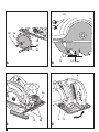
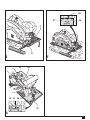
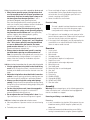
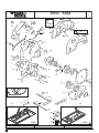
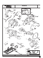
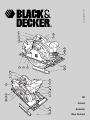
www.blackanddecker.com
2
1
6
3
5
17
4
8
7
10
13
11
9
12
2
1
3
17
6
5
4
16
10
9
8
7
UK
14
Ireland
11
15
12
Australia
New Zealand
1
23
20 19
22
18
21
2-3 mm
A
B
2-3 mm
13
6
24
12
C
2
5
25
D
11
28
27
8
26
7
11
E
F
33
14
30 31 29 32
15
G
3
Intended use
Your Black & Decker saw has been designed for sawing wood
and wood products.
This tool is intended for consumer use only.
General safety rules
Warning! Read all instructions. Failure to follow all instructions
listed below may result in electric shock, fire and/or serious
injury. The term “power tool” in all of the warnings listed
below refers to your mains operated (corded) power tool or
battery operated (cordless) power tool.
SAVE THESE INSTRUCTIONS.
1. Work area
a. Keep work area clean and well lit. Cluttered and dark
areas invite accidents.
b. Do not operate power tools in explosive atmospheres,
such as in the presence of flammable liquids, gases
or dust. Power tools create sparks which may ignite the
dust or fumes.
c. Keep children and bystanders away while
operating a power tool. Distractions can cause you to
lose control.
2. Electrical safety
a. Power tool plugs must match the outlet. Never modify
the plug in any way. Do not use any adapter plugs
with earthed (grounded) power tools. Unmodified
plugs and matching outlets will reduce risk of electric shock.
b. Avoid body contact with earthed or grounded
surfaces such as pipes, radiators, ranges and
refrigerators. There is an increased risk of electric shock
if your body is earthed or grounded.
c. Do not expose power tools to rain or wet conditions.
Water entering a power tool will increase the risk of
electric shock.
d. Do not abuse the cord. Never use the cord for
carrying, pulling or unplugging the power tool.
Keep cord away from heat, oil, sharp edges or
moving parts. Damaged or entangled cords increase the
risk of electric shock.
e. When operating a power tool outdoors, use an
extension cord suitable for outdoor use. Use of a cord
suitable for outdoor use reduces the risk of electric shock.
3. Personal safety
a. Stay alert, watch what you are doing and use common
sense when operating a power tool. Do not use a
power tool while you are tired or under the influence
of drugs, alcohol or medication. A moment of
inattention while operating power tools may result in
serious personal injury.
4
b. Use safety equipment. Always wear eye protection.
Safety equipment such as dust mask, non-skid safety
shoes, hard hat, or hearing protection used for
appropriate conditions will reduce personal injuries.
c. Avoid accidental starting. Ensure the switch is in
the off position before plugging in. Carrying power
tools with your finger on the switch or plugging in power
tools that have the switch on invites accidents.
d. Remove any adjusting key or wrench before turning
the power tool on. A wrench or a key left attached to a
rotating part of the power tool may result in personal injury.
e. Do not overreach. Keep proper footing and balance
at all times. This enables better control of the power tool
in unexpected situations.
f. Dress properly. Do not wear loose clothing or
jewellery. Keep your hair, clothing and gloves away
from moving parts. Loose clothes, jewellery or long hair
can be caught in moving parts.
g. If devices are provided for the connection of dust
extraction and collection facilities, ensure these
are connected and properly used. Use of these
devices can reduce dust related hazards.
4. Power tool use and care
a. Do not force the power tool. Use the correct power
tool for your application. The correct power tool will do
the job better and safer at the rate for which it was designed.
b. Do not use the power tool if the switch does not
turn it on and off. Any power tool that cannot be controlled
with the switch is dangerous and must be repaired.
c. Disconnect the plug from the power source before
making any adjustments, changing accessories, or
storing power tools. Such preventive safety measures
reduce the risk of starting the power tool accidentally.
d. Store idle power tools out of the reach of children
and do not allow persons unfamiliar with the power
tool or these instructions to operate the power tool.
Power tools are dangerous in the hands of untrained users.
e. Maintain power tools. Check for misalignment or
binding of moving parts, breakage of parts and any
other condition that may affect the power tools
operation. If damaged, have the power tool repaired
before use. Many accidents are caused by poorly
maintained power tools.
f. Keep cutting tools sharp and clean. Properly maintained
cutting tools with sharp cutting edges are less likely to
bind and are easier to control.
g. Use the power tool, accessories and tool bits etc.,
in accordance with these instructions and in the
manner intended for the particular type of power
tool, taking into account the working conditions
and the work to be performed. Use of the power tool
for operations different from those intended could result
in a hazardous situation.
5. Service
a. Have your power tool serviced by a qualified repair
person using only identical replacement parts. This
will ensure that the safety of the power tool is maintained.
– when the blade is pinched or bound tightly by the kerf
closing down, the blade stalls and the motor reaction
drives the unit rapidly back toward the operator;
– if the blade becomes twisted or misaligned in the cut, the
teeth at the back edge of the blade can dig into the top
surface of the wood causing the blade to climb out of the
kerf and jump back toward the operator.
Kickback is the result of saw misuse and/or incorrect
operating procedures or conditions and can be avoided by
taking proper precautions as given below.
◆
Safety instructions for all saws
Danger:
◆
◆
◆
◆
◆
◆
◆
◆
Keep hands away from cutting area and the blade.
Keep your second hand on auxiliary handle, or
motor housing. If both hands are holding the saw, they
cannot be cut by the blade.
Do not reach underneath the workpiece. The guard
cannot protect you from the blade below the workpiece.
Adjust the cutting depth to the thickness of the
workpiece. Less than a full tooth of the blade teeth
should be visible below the workpiece.
Never hold piece being cut in your hands or across
your leg. Secure the workpiece to a stable platform.
It is important to support the work properly to minimize
body exposure, blade binding, or loss of control.
Hold power tool by insulated gripping surfaces
when performing an operation where the cutting
tool may contact hidden wiring or its own cord.
Contact with a “live” wire will also make exposed metal
parts of the power tool “live” and shock the operator.
When ripping always use a rip fence or straight
edge guide. This improves the accuracy of cut and
reduces the chance of blade binding.
Always use blades with correct size and shape
(diamond versus round) of arbour holes. Blades that
do not match the mounting hardware of the saw will run
eccentrically, causing loss of control.
Never use damaged or incorrect blade washers or
bolt. The blade washers and bolt were specially designed
for your saw, for optimum performance and safety of
operation.
◆
◆
◆
◆
◆
◆
Maintain a firm grip with both hands on the saw
and position your arms to resist kickback forces.
Position your body to either side of the blade, but
not in line with the blade. Kickback could cause the
saw to jump backwards, but kickback forces can be
controlled by the operator, if proper precautions are taken.
When blade is binding, or when interrupting a cut
for any reason, release the trigger and hold the saw
motionless in the material until the blade comes to
a complete stop. Never attempt to remove the saw
from the work or pull the saw backward while the
blade is in motion or kickback may occur. Investigate
and take corrective actions to eliminate the cause of
blade binding.
When restarting a saw in the workpiece, centre the
saw blade in the kerf and check that saw teeth are
not engaged into the material. If saw blade is binding,
it may walk up or kickback from the workpiece as the saw
is restarted.
Support large panels to minimise the risk of blade
pinching and kickback. Large panels tend to sag under
their own weight. Supports must be placed under the
panel on both sides, near the line of cut and near the
edge of the panel.
Do not use dull or damaged blades. Unsharpened or
improperly set blades produce narrow kerf causing
excessive friction, blade binding and kickback.
Blade depth and bevel adjusting locking levers must
be tight and secure before making cut. If blade
adjustment shifts while cutting, it may cause binding and
kickback.
Use extra caution when making a “plunge cut” into
existing walls or other blind areas. The protruding
blade may cut objects that can cause kickback.
Further safety instructions for all saws
Causes and operator prevention of kickback:
– kickback is a sudden reaction to a pinched, bound or
misaligned saw blade, causing an uncontrolled saw to lift
up and out of the workpiece toward the operator;
5
Safety instructions for saws with a pendulum blade guard
◆ Check lower guard for proper closing before each
use. Do not operate the saw if lower guard does not
move freely and close instantly. Never clamp or tie
the lower guard into the open position. If saw is
accidentally dropped, lower guard may be bent.
Raise the lower guard with the retracting handle and
make sure it moves freely and does not touch the blade or
any other part, in all angles and depths of cut.
◆ Check the operation of the lower guard spring. If
the guard and the spring are not operating properly,
they must be serviced before use. Lower guard may
operate sluggishly due to damaged parts, gummy
deposits, or a build-up of debris.
◆ Lower guard should be retracted manually only for
special cuts such as “plunge cuts” and “compound
cuts.” Raise lower guard by retracting handle and
as soon as blade enters the material, the lower
guard must be released. For all other sawing, the lower
guard should operate automatically.
◆ Always observe that the lower guard is covering
the blade before placing saw down on bench or
floor. An unprotected, coasting blade will cause the saw
to walk backwards, cutting whatever is in its path. Be
aware of the time it takes for the blade to stop after
switch is released.
Additional safety instructions for all saws with riving knife
◆ Use the appropriate riving knife for the blade being
used. For the riving knife to work, it must be thicker than
the body of the blade but thinner than the tooth set of the
blade.
◆ Adjust the riving knife as described in this instruction
manual. Incorrect spacing, positioning and alignment can
make the riving knife ineffective in preventing kickback.
◆ Always use the riving knife except when plunge
cutting. Riving knife must be replaced after plunge cutting.
Riving knife causes interference during plunge cutting and
can create kickback.
◆ For the riving knife to work, it must be engaged in
the workpiece. The riving knife is ineffective in
preventing kickback during short cuts.
◆ Do not operate the saw if riving knife is bent. Even a
light interference can slow the closing rate of a guard.
Additional safety instructions for circular saws
◆ Wear ear protectors. Exposure to noise can cause hearing
loss.
◆ Preferably wear a dust mask.
6
◆
◆
Do not use blades of larger or smaller diameter than
recommended. For the proper blade rating refer to the
technical data. Use only the blades specified in this
manual, complying with EN 847-1.
Never use abrasive cut-off wheels.
Electrical safety
This tool is double insulated; therefore no earth wire
is required. Always check that the power supply
corresponds to the voltage on the rating plate.
◆
◆
This appliance is not intended for use by young or infirm
persons without supervision. Children must be supervised
to ensure they do not play with the appliance.
If the supply cord is damaged, it must be replaced by the
manufacturer or an authorised Black & Decker Service
Centre in order to avoid a hazard.
Overview
1.
2.
3.
4.
5.
6.
7.
8.
9.
10.
11.
12.
13.
14.
15.
16.
17.
On/off switch
Lock-off button
Main handle
Secondary handle
Locking knob for depth of cut adjustment
Depth of cut scale
Locking knob for mitre angle adjustment
Mitre angle scale
Saw blade guard
Retracting lever for saw blade guard
Saw shoe
Parallel fence
Riving knife
Window (KS65K)
Sight guide (KS65K)
Spindle lock (KS65K)
Saw dust outlet
Assembly
Warning! Before attempting any of the following operations,
make sure that the tool is switched off and unplugged and
that the saw blade has stopped.
Removing and fitting a saw blade (fig. A)
Removing
◆ Insert a screwdriver into the hole (18) to prevent the saw
blade from rotating. KS65K: keep the spindle lock (16)
depressed.
◆ Loosen and remove the blade retaining screw (20) by
turning it counterclockwise using the spanner supplied.
◆
◆
Remove the outer washer (19).
Remove the saw blade (21).
Fitting
◆ Place the saw blade onto the inner washer (22), making
sure that the arrow on the blade points in the same
direction as the arrow on the tool.
◆ Fit the outer washer (19) on the spindle, with the raised
part pointing away from the saw blade.
◆ Insert the blade retaining screw (20) into the hole.
◆ Insert a screwdriver into the hole (18) to prevent the saw
blade from rotating. KS65K: keep the spindle lock (16)
depressed.
◆ Securely tighten the blade retaining screw by turning it
clockwise using the spanner supplied.
◆ Adjust the riving knife as described below.
Adjusting the riving knife (fig. B)
The riving knife prevents the saw blade from jamming during
rip sawing operations. The riving knife must be adjusted after
replacing the saw blade.
◆ KS64(K)/KS65K: set the saw shoe to the minimum depth
of cut as described below. KS55: the screws (23) can be
accessed through the holes in the guard.
◆ Loosen the two screws (23).
◆ Position the riving knife (13) as shown.
– The distance between the toothed rim and the riving
knife should be 2 - 3 mm.
– The height difference between the toothed rim and the
lower end of the riving knife should be 2 - 3 mm.
◆ Tighten the screws (23).
Fitting and removing the parallel fence (fig. C)
The parallel fence is used to saw in a straight line parallel to
the edge of the workpiece.
Fitting
◆ Loosen the locking knob (24).
◆ Insert the parallel fence (12) through the openings (25).
◆ Slide the parallel fence into the desired position.
◆ Tighten the locking knob.
Removing
◆ Loosen the locking knob (24).
◆ Pull the parallel fence off the tool.
Use
Warning! Let the tool work at its own pace. Do not overload.
This tool can be used in the right hand or the left hand.
Warning! Carefully guide the cable in order to avoid
accidentally cutting it.
Adjusting the depth of cut (fig. D)
The depth of cut should be set according to the thickness of
the workpiece. It should exceed the thickness by approx. 2 mm.
◆ Loosen the knob (5) to unlock the saw shoe.
◆ Move the saw shoe (11) into the desired position.
The corresponding depth of cut can be read from the scale (6).
◆ Tighten the knob to lock the saw shoe in place.
Adjusting the mitre angle (fig. E)
This tool can be set to mitre angles between 0° and 45°.
◆ Loosen the locking knob (7) to unlock the saw shoe.
◆ Move the saw shoe (11) into the desired position.
The corresponding mitre angle can be read from the scale (8).
◆ Tighten the locking knob to lock the saw shoe in place.
Switching on and off
Warning! Before switching on, make sure that the spanner
has been removed from the blade retaining screw and that the
screwdriver has been removed from the tool.
Switching on
◆ Keep the lock-off button (2) depressed and press the
on/off switch (1).
◆ Release the lock-off button.
Switching off
◆ Release the on/off switch.
KS55/KS64(K) - Aligning the saw with the cutting line
(fig. F)
The saw is equipped with guides for straight cutting (26) and
guides for 45° mitre cutting (27).
◆ Align the left edge of the guides (26) or (27) with the
cutting line (28).
For very accurate cuts:
◆ Mark a cutting line on a scrap piece of wood.
◆ Align the left edge of the guides (26) or (27) with the
cutting line (28).
◆ Make a test cut.
◆ Depending on the results, adjust the position of the
guides relative to the cutting line.
KS65K - Adjusting the sight guide (fig. G)
◆ While viewing through the window (14), align the saw
blade teeth with the cutting line.
◆ While keeping the saw in this position, loosen the sight
guide (15) on the saw shoe (11) as shown.
◆ Align the 0° mark (29) on the sight guide with the cutting
line (31). When adjusting for 45° mitre cuts, align the 45°
mark (30) on the sight guide with the cutting line.
◆ Secure the sight guide using the screw (32).
7
KS65K - Using the sight guide (fig. G)
◆ Adjust the sight guide (15) as described above.
◆ Before operating the saw, look through the window (14) to
align the saw with the cutting line. Keep the sight guide
(15) aligned with the cutting line while sawing.
Dust extraction
An adaptor is required to connect a vacuum cleaner or dust
extractor to the tool. The adaptor can be purchased from your
local Black & Decker retailer.
◆ Insert the dust extraction adaptor into the saw dust outlet
(17).
◆ Connect the vacuum cleaner hose to the adaptor.
Hints for optimum use
◆ As some splintering along the line of cut on the top side of
the workpiece cannot be avoided, cut on the side where
splintering is acceptable.
◆ Where splintering is to be minimised, e.g. when cutting
laminates, clamp a piece of plywood onto the top of the
workpiece.
Accessories
The performance of your tool depends on the accessory used.
Black & Decker and Piranha accessories are engineered to high
quality standards and designed to enhance the performance of
your tool. By using these accessories you will get the very best
from your tool.
Maintenance
Your tool has been designed to operate over a long period of
time with a minimum of maintenance. Continuous satisfactory
operation depends upon proper tool care and regular cleaning.
◆ Regularly clean the ventilation slots with a clean,
dry paint brush.
◆ To clean the tool, use only mild soap and a damp cloth.
Never let any liquid get inside the tool and never immerse
any part of the tool into liquid.
Mains plug replacement (U.K. & Ireland only)
If a new mains plug needs to be fitted:
◆ Safely dispose of the old plug.
◆ Connect the brown lead to the live terminal in the new plug.
◆ Connect the blue lead to the neutral terminal.
Warning! No connection is to be made to the earth terminal.
Follow the fitting instructions supplied with good quality plugs.
Recommended fuse: 13 A.
8
Protecting the environment
Separate collection. This product must not be
disposed of with normal household waste.
Should you find one day that your Black & Decker product
needs replacement, or if it is of no further use to you, do not
dispose of it with household waste. Make this product
available for separate collection.
Separate collection of used products and packaging
allows materials to be recycled and used again.
Re-use of recycled materials helps prevent
environmental pollution and reduces the demand for
raw materials.
Local regulations may provide for separate collection of
electrical products from the household, at municipal waste
sites or by the retailer when you purchase a new product.
Black & Decker provides a facility for the collection and
recycling of Black & Decker products once they have reached
the end of their working life. To take advantage of this service
please return your product to any authorised repair agent who
will collect them on our behalf.
You can check the location of your nearest authorised repair
agent by contacting your local Black & Decker office at the
address indicated in this manual. Alternatively, a list of
authorised Black & Decker repair agents and full details of our
after-sales service and contacts are available on the Internet
at: www.2helpU.com
Technical data
Input voltage
(Australia & New Zealand)
Power input
No-load speed
Max. depth of cut
Blade diameter
Blade bore
Blade tip width
LpA (sound pressure)
KpA (sound pressure uncertainty)
LWA (acoustic power)
KWA (acoustic power uncertainty)
Hand/arm weighted vibration
Weight
VAC
VAC
W
min-1
mm
mm
mm
mm
dB(A)
dB(A)
dB(A)
dB(A)
m/s2
kg
KS55
230
240
1,200
5,000
55
170
16
2.6
93.2
3
104.2
3
1.74
5.4
KS64
230
KS65
230
1,300
5,000
65
190
16
2.6
95.0
3
106.0
3
2.20
5.4
1,400
5,000
65
190
16
2.6
95.0
3
106.0
3
2.20
5.4
EC declaration of conformity
KS55/KS64/KS65
Black & Decker declares that these products conform to:
98/37/EC, 89/336/EEC, EN 60745, EN 55014, EN 61000
Kevin Hewitt
Director of Consumer Engineering
Spennymoor, County Durham DL16 6JG,
United Kingdom
1-5-2006
Guarantee
Black & Decker is confident of the quality of its products and
offers an outstanding guarantee. This guarantee statement is
in addition to and in no way prejudices your statutory rights.
The guarantee is valid within the territories of the Member
States of the European Union and the European Free Trade
Area.
If a Black & Decker product becomes defective due to faulty
materials, workmanship or lack of conformity, within 24 months
from the date of purchase, Black & Decker guarantees to
replace defective parts, repair products subjected to fair wear
and tear or replace such products to ensure minimum
inconvenience to the customer unless:
◆ The product has been used for trade, professional or hire
purposes;
◆ The product has been subjected to misuse or neglect;
◆ The product has sustained damage through foreign
objects, substances or accidents;
◆ Repairs have been attempted by persons other than
authorised repair agents or Black & Decker service staff.
To claim on the guarantee, you will need to submit proof of
purchase to the seller or an authorised repair agent. You can
check the location of your nearest authorised repair agent by
contacting your local Black & Decker office at the address
indicated in this manual. Alternatively, a list of authorised
Black & Decker repair agents and full details of our after-sales
service and contacts are available on the Internet at:
www.2helpU.com.
Please register at our website www.blackanddecker.com
to be kept up to date on new products and special offers.
Further information on the Black & Decker brand and our range
of products is available at www.blackanddecker.com.
9
TYP
1
KS55 KS64
19
3
55
20
35
4
KS55
24
55
36
56
18
14
17
KS64
57
13
5
53
15
3
23
22
40
16
1
6
3
2
7
29
51
21
10
39
38
52
41
37
28
42
2.5
2.
0
27
25
32
9
49
31
43
30
33
50
54
46
30
34
816
817
KS64
E13203
10
821
WWW.2helpU.com
KS55
16 - 07 - 01
TYP
1
KS65K
3
19
20
67
70
24
69
78
14
77
68
18
66
13
17
65
63
72
64
55
15
73
74
3
23
22
4
55
36
56
57
53
40
16
5
1
6
2
3
7
29
51
21
10
39
38
52
41
37
28
42
27
31
25
43
58
46
32
9
61
62
59
76
75
49
60
50
71
816
30
33
821
34
E13216
WWW.2helpU.com
817
2.5
2.
0
54
23 - 07 - 01
11
Australia
Black & Decker (Australia) Pty. Ltd. Tel. 03-8720 5100
20 Fletcher Road, Mooroolbark,
Fax 03-9727 5940
Victoria, 3138
New Zealand
Black & Decker
81 Hugo Johnston Drive
Penrose, Auckland, New Zealand
United Kingdom
Black & Decker
210 Bath Road
Slough, Berkshire SL1 3YD
573644-03
12
Tel. 09 579 7600
Fax 09 579 8200
Tel. 01753 511234
Fax 01753 551155
Helpline 01753 574277
05/06