1
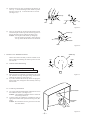
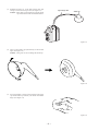
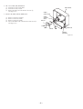
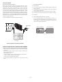
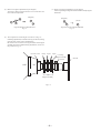
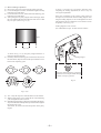
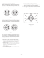
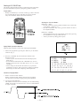
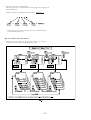
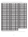
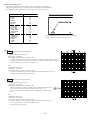
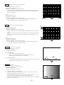
TV-SA2155
KE
SERVICE MANUAL
COLOR TELEVISION
S/M Code No. 09-00B-431-4S1
SU
PP
LE
ME
DA
NT
TA
• This Service Manual contains the additional information “DISASSEMBLY
INSTRUCTIONS” and “ADJUSTMENT” for the model TV-SA2155 (KE).
If requiring the other information, see Service Manual of TV-SA2155 (KE),
(S/M Code No. 09-005-431-4R1).
DISASSEMBLY INSTRUCTIONS
1. REAR CABINET REMOVAL
(1)
Remove four screws 1 and three screws 2 , then remove
the rear cabinet in the direction of the arrow.
(See Figure1-1)
Front cabinet
Rear cabinet
Figure 1-1
2. HIGH-VOLTAGE CAP (ANODE CAP) REMOVAL
2-1. Cautions before Removing
Anode cap
Discharge the anode voltage
(1)
The anode voltage is not discharged completely from the
CRT of this unit even after the power is turned off. Be
sure to discharge the residual anode voltage before
removing the anode cap.
CRT GND
Do not use pliers
(2)
Do not use pliers, etc. to remove the anode cap. If you
used pliers and bent the hook to remove the cap, the spring
characteristics of the hook could be lost, and when
reinstalled, the cap would come off from the CRT anode
button easily, causing an accident.
(3)
If the anode cap is turned in the direction of its
circumference, the hook is likely to come off.
Do not turn the anode cap
Grip
CRT
Hook
CRT GND
Figure 2-1
2-2. Anode Cap Removal
(1)
(2)
(3)
(4)
Discharge the anode voltage. (See Figure 2-1)
Connect a flat-bladed screwdriver to the CRT GND via
an alligator clip.
Use a tester to check the end of the screwdriver and ground
of the TV for continuity.
Touch the hook with the end of the screwdriver.
Caution : Be careful not to damage the anode cap.
Turn over the anode cap.
Caution : Be careful not to damage the anode cap.
Anode cap
CRT
Anode button
Hook
Figure 2-2
–2–
(5)
Push the anode cap with your thumb in the direction of
arrow 1 as shown in the figure, then lift the cap in the
direction of arrow 2 to release the hook on one side.
(See Figure 2-3)
Anode cap
CRT
CRT
Hook
Hook
Figure 2-3
(6)
Turn over the anode cap on the side where the hook was
released and pull out the cap in the direction opposite to
that on which the cap was pushed. (See Figure 2-4)
Caution : Do not pull out the anode cap straight up.
: Do not pull the cap forcibly. After removing
the cap, check that the hook is not deformed.
Anode cap
CRT
Anode button
Hook
Figure 2-4
3. ANODE CAP REINSTALLTION
Anode cap
Observe the cautions carefully so that no accident occurs
due to a defect in installing the anode cap and so it does
not come off.
Left
Right
3-1. Caution before Reinstalling
Never turn the anode cap after installing it
Never re-use the hook when it has been deformed
(1)
(2)
If the anode cap is turned after it is installed, it may come
off. Therefore, arrange the high-voltage cable before
attaching the anode cap. (See Figure 3-1)
If you have attached the anode cap before arranging the
high-voltage cable, arrange the cable carefully so the cap
does not turn.
Figure 3-1
3-2. Anode cap reinstallation
(1)
(2)
Anode button
Use a clean cloth moistened slightly with alcohol to clean
the installation section. (See Figure 3-2)
Caution : Check that the installation section is free from
dust, foreign matter, etc.
Coat the anode cap installation circumference with an
appropriate amount of the specified silicone grease (KS650N).
Caution : Be careful that silicone grease does not enter
the anode button.
Installation
section
–3–
Figure 3-2
(3)
Eliminate twisting, etc. of the high-voltage cable and
arrange it so that no twisting occurs. (See Figure 3-3)
Caution : If the cable is not arranged correctly, the anode
cap could turn and cause an installation defect.
High-voltage cable
Anode cap
Figure 3-3
(4)
Turn over the rubber cap symmetrically on the left and
right. (See Figure 3-4)
Caution : Take great care not to damage the anode cap.
Figure 3-4
(5)
Fit your forefinger over the projection at the center of the
cap and hold the cap between your thumb and middle
finger. (See Figure 3-5)
Figure 3-5
–4–
(6)
(7)
Apply the hook on one side to the anode button as shown
on the figure. (See Figure 3-6)
Caution : Check that the hook is held securely.
Apply the hook on the other side to the anode button as
shown in Figure 3-7.
Hook
Anode button
Hook
Anode button
30°
Figure 3-6
Anode button
Hook
Figure 3-7
(8)
Pull the anode cap slightly with the rubber cap turned
over and visually check that the hook is engaged securely.
(9) Release your hand from the rubber cap of the anode cap.
Caution : Cover the anode cap so that it does not lift.
(10) Hold the skirt of the andoe cap slightly to improve the
close contact between the cap and CRT.
(11) Check that the anode cap is in close contact with the CRT.
(See Figure 3-8)
Anode button
Skirt
Figure 3-8
–5–
4. NK C.B. (PWB, NK) REMOVAL
(1)
(2)
(3)
Disconnect CN553 (CRT GND).
Disconnect CN551, CN552
Remove the NK C.B. in the direction of arrow 1.
(See Figure 4-1)
Front cabinet
CN801
(Power Cord)
5. MAIN C.B (PWB, MAIN) REMOVAL
(1)
(2)
(3)
(4)
Remove connector (CNA900).
Remove connector (CN801).
Remove connector (CN802).
Pull out the MAIN C.B. in the direction of the arrow 2
(See Figure 4-1).
CN802
(Degauss
cord)
NK C.B
CN552
CN551
MAIN C.B
CN553
CNA900
(Speakers)
Figure 4-1
–6–
ADJUSTMENT
SET-UP FOR ADJUSTMENT
1. CRT ADJUSTMENT
1-1. Precautions
Because the video signal output from a pattern generator is used as
the adjustment signal input during adjustment, the video signal
output from the pattern generator must conform with the
specifications. Measure the output waveform across 75 Ω load.
Confirm that the synchronizing signal has an amplitude of about
0.3 V, the video signal portion has an amplitude of about 0.7 V and
the burst signal has an amplitude of about 0.3 V with flat envelope.
Confirm that ratio of the burst signal amplitude and the red signal
amplitude is 0.30 : 0.66. If the output signal does not conform with
the specifications, calibrate the pattern generator. (Refer to pattern
generator operation manual.)
Use the LEADER: LCG 404 for the pattern generator.
(1) Receive the white raster signal, and then perform aging for at
least 20 minutes.
(2) Demagnetize the area surronding the CRT with a degausser
before making adjustments.
(3) Set the picture quality for each mode to the factory setting.
(4) Position the front screen facing the east as much as possible.
1-2. Purpose
(1) Beam landing adjustment (purity magnet)
Set the left/right balance of beam landing. If there is a
discrepancy in this adjustment, a color irregularity will occur.
After completion of the landing adjustment, it is necessary to
perform convergence adjustment.
Approx. 0.7V
1 Vp-p White (Approx.
75%)
Burst signal
Before adjustment
Approx.
0.3V
Color
irregularity
Black
Red
Blue
Magenta
Cyan
Fig. 1-1
Green
75% white
Yellow
Approx. 0.3V
After adjustment
TV display
Color bar signal of a pattern generator
PRECAUTIONS BEFORE STARTING ADJUSTMENT
Satisfy the following setting conditions before starting adjustment.
• Allow warm-up of 20 minutes or longer. (Do not turn off during
warm-up.)
• Set all picture quality controls of users' setting to initial set-up,
unless otherwise specified.
• Picture quality reset
1. Select "Picture" on the screen menu and press enter button.
2. Select "Normal" and press enter button.
3. Select "Reset" and press enter button.
• Set the pattern generator’s output level to 1.0Vp-p (across 75Ω
load).
–7–
(3) Beam convergence adjustment (6-pole magnet)
With a 4-pole magnet align the G beam with the already aligned
R/B beam.
(2) Beam convergence adjustment (4-pole magnet)
Align the R beam with the B beam. The G beam does not
move with this adjustment.
(magenta)
(magenta)
B
R/B
R
G
(white)
R/B
G
G
RGB
Align the G beam with the R/B beam
Fig. 1-3
Align the R beam with the B beam
Fig. 1-2
(4) The composition of each magnet is as shown in Fig. 1-4.
In making adjustments, rotate the lock ring clockwise (looking
from the CRT’s back screen) and disengage.
Be careful not to loose the lock ring too much. If the magnet
assembly has become shifted during adjustments, secure it to
the position in Fig. 1-4.
DY lock screw
Purity 4-pole 6-pole Lock ring
Magnet assembly
lock screw
CRT
DY
Magnet assembly
Fig 1-4
–8–
NK C.B
1-3. Beam Landing Adjustment
(1) Receive the green raster signal from the pattern generator.
(2) Loosen the magnet lock screw, and shift the magnet assembly
backward (toward the neck).
(3) Loosen the DY lock screw, and shift the DY deflecting yoke
backward (toward the neck).
(4) After opening the two purity magnets to the same angle, adjust
the color width of the bands on both sides of the screen so that
they are equal. (refer to Fig. 1-5 (a)).
As there is occurrence of convergence distortion after
completing the landing adjustments, be sure to carry out
convergence adjustments.
If the color irregularities in the screen’s corner section are
not improved, correct them with the landing magnet. After
using the landing magnet, be sure to demagnetize the CRT
with degausser and verify that there is no occurrence of color
irregularity. (refer to Fig. 1-6)
Landing magnet: 81-JTI-710-010
(two-sided adhesive tape) : 80-XVI-218-010 Cushion
R=B
R
G
B
Fig 1-5 (a)
As shown in Fig. 1-5 (b), the purity magnet functions in
relation to the electron beam.
(5) Gradually shift the deflecting yoke toward the front (toward
the CRT funnel). Stop movement at the point when the screen
has become completely green.
S
N
N
S
NS
Landing magnet
Cushion
SN
Since the landing magnet is polarized,
check the screen’s improvement through
rotation, not only by position.
S
S
N
N
SS
Fig 1-6
NN
Fig 1-5 (b)
(6) Also, verify the respective monochromatics of red and blue.
(7) While looking at the screen, adjust the tilt of the deflecting
yoke and tighten the DY lock screw.
(8) Shift the magnet assembly to the front (toward the CRT funnel),
stop movement before the adjustment position and then tighten
the magnet lock screw.
At this time, be careful not to shift the position of the purity
magnet.
–9–
1-4. Beam Center Convergence Adjustment
1-5. The Surrounding Convergence Adjustment
Make adjustments on the convergence with 4-pole and 6-pole
magnets. Operate each magnet in relation to the electron beam as
shown in Figs. 1-7 and 1-8. When performing this adjustment, verify
whether there is distortion in the focus adjustment. If necessary,
carry out adjustments again.
Perform this adjustment after completion of adjustment 1-4.
(1) Shake the deflecting yoke up, down to the right and left, and
adjust any discrepancies in the screen’s surroundings.
(2) Insert wedges in three locations in the gap between the
deflecting yoke and the surface of the CRT funnel in order
to secure the deflecting yoke. (Refer to Fig. 1-9)
S
S
B
N
G
B
N
R
G
R
N
Wedge
N
S
S
Fig 1-7
Wedge
Wedge
In Fig. 1-7, two 4-pole magnets are stacked together so as to be of
the same polarity. Move the B and R beams to their respective
direction, by rotating the two 4-pole magnets together. By adjusting
the opening of the two magnets, it is possible to adjust the amount
of the beam’s movement.
Position of wedge
N
S
S
N
Fig. 1-9
S
B
G
R
N
B
G
R
S
N
N
S
S
N
Fig 1-8
In Fig. 1-8, the two 6-pole magnets are stacked together so as to be
of the same polarity. Move the B and R beams to their respective
direction, by rotating the two 6-pole magnets together. By adjusting
the opening of the two magnets, it is possible to adjust the amount
of the beam’s movement.
(1) Receive the dot pattern signal from the pattern generator.
(2) Pay attention to the center of the screen, and perform
adjustments with two 4-pole magnets so that the R beam and
B beam are perfectly aligned and become a magenta color.
(Refer to Fig. 1-2)
(3) In the same way, pay attention to the screen, and perform
adjustments with a 6-pole magnet so that the magenta beam
and G beam are aligned and become a white dot.
(Refer to Fig. 1-3)
(4) After adjustments are completed, secure all magnets with the
lock link. (Refer to Fig. 1-4)
– 10 –
Setting of IIC BUS Data
This model is designed with the ability to adjust most parts of the image
projection and deflection system by using the jig remote controller.
Preparations :
•
Modify the hidden keys on the RC-6VT06 jig remote controller
(TV-C142/86-LB4-951-010) so that they can easily be pressed.
2 keys to be modified. (Refer to the below illustration)
Starting the “Service Mode” :
Hidden key / “TEST”
• Press the “TEST” key on the jig remote controller once to enter to the
“Aging Mode” (Refer Fig. 1).
• Press the “CHANNEL” key on the jig remote controller to enter to
the “Adjustment Mode”.
Hidden key / “FINISH”
• The accumulated hours in the “Aging Mode” will be reset by pressing
the “FINISH” key on the jig remote controller.
• Avoid to press this key during general repairs.
Aging Mode Operation Method :
Make sure that confirmation is done after replacing the EEP ROM.
1. Enter to the aging mode by pressing the “TEST” key on the remote
controller. (Fig. 1)
2. Press the “AV MODE” key and confirm the condition of the
distinction switch.
• Choose any one of the destination and check the display data.
(Refer Fig. 2).
• In case the data is different use the “CHANNEL” key to scroll
through 0~F and set to the correct data value of “0” or “1” by the
volume key.
• All the settings are stored when the “TEST” key is pressed to
complete the correction. There will not be a problem even though
these changes are done after completing all the adjustments.
1
2
3
4
0
1
0
1
KE1
KE2
INDO1
INDO2
1
0
1
0
2
0
2
1
5
6
7
8
SH1
SH2
SH3
SH4
3 4 5 6 7 8 9 A B C D E F
1 0 1 0 0 1 1 1 1 0 0 0 1
3 4 5 6 7 8 9 A B C D E F
1 0 0 1 0 0 0 1 1 0 0 0 0
Fig. 2
Contents of Aging Mode :
1. Release “Auto Power Off” function
Release “Auto Power Off” function when no input is supplied.
Use this mode for warming up (aging) during CRT adjustment.
2. AFT S-curve status indication
The condition of AFT S-curves are indicated by “IN” for suitable tuning,
“HIGH” for too high or “LOW” for too low. “OUT” is indicated when
no signal is supplied.
– 11 –
3. Display of “CRT ON” accumulated hours
The CRT usage time is accumulated on an hourly basis and is displayed in
hexadecimal figures.
Sample calculation of displayed hexadecimal figures : HEX 1 2 3 4
• The display will be reset to 0000H when the accumulated hours
exceed 7FFFH(32768 hours).
Adjustment Mode Operation Method :
1. Return to the aging display by pressing the “TEST” key and press
“CHANNEL” key to display the adjustment menu screen.
– 12 –
The menus from No.0 to 101 inclusive of PAGE 1 to 3 serve as the “Adjustment Menu” . (Refer to the following tables)
No.
Menus
Reference
Values
No.
Menus
Reference
Values
No.
Menus
Reference
Values
0
CONT
20
35
BRIGHT MAX
7F
70
SELF ADJ
–
1
COLOR
10
36
CONT MIN
00
71
ID SENSIV
–
2
SHARPNESS
20
37
CONT MAX
3F
72
SECAM ADJ
–
3
SUB CONTRAST
0A
38
COLOR NTSC
40
73
AFT ON
–
4
V LINEA
07
39
COLOR MIN
00
74
YM EMB
–
5
V S CORR
08
40
COLOR SECAM
40
75
YUV SW
–
6
ABL START
02
41
COLOR MAX
7F
76
AFC GAIN
00
7
IF FEAQ
04
42
RG CONT MAX
30
77
V LINEA 60
07
8
BGP P
00
43
SHARP MIN
00
78
H SIZE 60
–
9
PARABOLA
–
44
SHARP MAX
3F
79
PARABOLA 60
–
10
TRAPEZIUM
–
45
SHARP NT
20
80
TRAPEZIUM 60
–
11
V. EHT
–
46
SHARP NT VIDEO
20
81
V. EHT 60
–
12
CORNER
–
47
SHARP VIDEO
20
82
CORNER 60
–
13
H. EHT
–
48
TINT MIN
00
83
H. EHT 60
–
14
H POS
0B
49
TINT MAX
7F
84
V S CORR 60
09
15
V POS
03
50
TXT RGB MAC
2D
85
V SIZE 60
23
16
OSD H
15
51
ABL GAIN
00
86
V POS 60
00
17
PIF VCO
80
52
V AGC
00
87
H POS 60
0E
18
RF AGC
3F
53
WHITE PEAK
00
88
OSD H 60
14
19
R CUTOFF
80
54
MUTE
–
89
OSD V 60
08
20
G CUTOFF
80
55
AF GAIN
–
90
G VSIZE SHIFT
02
21
B CUTOFF
80
56
VIDEO POL
–
91
G HSIZE SHIFT
00
22
G DRV GAIN
40
57
BPF/TOF
–
92
G VPOS SHIFT
00
23
B DRV GAIN
40
58
CHROMA TRAP
–
93
G HPOS SHIFT
00
24
BRIGHT
40
59
HALF TONE
–
94
OSD V
09
25
SEGAM B-Y
08
60
COLOR SYSTEM
–
95
VOL LOUDSPK
73
26
SEGAM R-Y
08
61
CW SW
–
96
FM MATRIX
01
27
RGB CONT
20
62
AFT MUTE
–
97
PRESCALE FM/AM
25
28
H SIZE
–
63
BLUE BACK
–
98
PRESCALE NICAM
56
29
V SIZE
20
64
DC NF SPEED
–
99
PRESCALE SCART
19
30
TINT
3F
65
V FREQ
–
100
NICAM IDL
03
31
TEST
–
66
NTSC COMB
–
101
NICAM IDH
0A
32
TEST 2
–
67
BLACKING
–
33
BRIGHT MIN
00
68
H OUT STOP
–
34
BRIGHT STEP
00
69
FORCED ID
–
*1. The indicated reference values are different from the actual data values.
*2. Depending on the model, all items which are described in the “Adjustment Mode” may not be always applicable. Refer to each adjustment.
– 13 –
Menu screen adjustment:
•
•
Operate after inputting the following initial figures when replacing EEP ROM.
These initial figures are only for reference purposes and meant for rough adjustment.
Check the condition and adjust the area where the general repair is carried out.
TV-A2115
PAGE 1
1. H POS
2. V POS
–––––
4. OSD H
5. PIF VCO
6. RF AGC
Sample Indication for Adjustment Menu No.
Initial Figures PAL (NTSC)
0B
03
––
15
80
3F
PAGE 2
1. R CUT OFF
2. G CUT OFF
3. B CUT OFF
4. G DRV GAIN
5. B DRV GAIN
6. BRIGHT
PAGE 3
1. SECAM B-Y
2. SECAM R-Y
3. RGB CONT
4. H SIZE
5. V SIZE
6. TINT
7F
7F
7F
40
40
40
08
08
00
00
20
3F
Each adjustment should be carried out after checking the
adjustment menu no. (Refer to the above Fig.)
Fig. 1
PAGE 1
1-1. H POS Horizontal Positioning Adjustment
PAL
Adjustment Menu No. 14 (Page 1-1)
Input signal : Crosshatch
Measuring instrument : Pattern generator / PAL
• Use the volume keys on the jig remote controller to adjust the dot mark in the centre of
crosshatch screen to the exact centering position by allocating an equal number of squares
on the left and right side of the dot. A=B (Fig. 1-1)
NTSC
Adjustment Menu No. 87
Input signal : Crosshatch
Measuring instrument : Pattern generator / NTSC
• Using the “CHANNEL” key, scroll through the adjustment menu and select No.87.
To adjust, follow the same procedure as PAL.
1-2. V POS Vertical Positioning Adjustment
PAL
Adjustment Menu No.15 (Page 1-2)
Input signal : Crosshatch
Measuring instrument : Pattern generator / PAL
• Using the volume keys on the jig remote controller, adjust the dot mark to the
exact vertical centre position in the crosshatch screen. (Fig. 1-2)
* In case of being unable to adjust by the above mentioned procedure, adjust
S501.
NTSC
Adjustment Menu No. 86
Input signal : Crosshatch
Measuring instrument : Pattern generator / NTSC
• Use the “CHANNEL” key to scroll through the adjustment menu and select
No. 86. To adjust, follow the same procedure as PAL.
* Do not adjust S501 for NTSC.
– 14 –
1-3. OSD H OSD Horizontal Positioning Adjustment
PAL
Adjustment Menu No. 16 (Page 1-4)
Input signal : Crosshatch
Measuring instrument : Pattern generator / PAL
• Use the volume keys on the jig remote controller to adjust each A and B positions
on both left and right in the equal distance towards the screen edge in the OSD
display. A = B (Fig. 1-3)
NTSC
Adjustment Menu No. 88
Input signal : Crosshatch
Measuring instrument : Pattern generator / NTSC
• Use the “CHANNEL” key to scroll through the adjustment menu and select
No.88. To adjust, follow the same procedure as PAL.
1-4. OSD V OSD Vertical Positioning Adjustment
PAL
Adjustment Menu No. 94
Input signal : Crosshatch
Measuring instrument : Pattern generator / PAL
• Use the “CHANNEL” key to scroll through the adjustment menu screen and select
No.94.
• Using the volume keys on the jig remote controller, adjust A and B on both top and
bottom shown in the OSD screen to be equidistant from the screen edges. A = B
(Fig. 1-4)
NTSC
Adjustment Menu No. 89
Input signal : Crosshatch
Measuring instrument : Pattern generator / NTSC
• Use the “CHANNEL” key to scroll through the adjustment menu and select No.
89. To adjust, follow the same procedure as PAL.
1-5. PIF VCO Video IF • VCO Adjustment
Adjustment Menu No.17 (Page 1-5)
Input signal : No signal
Test point : IC3011PIN
1-5.1 Auto Adjustment
•
Press “ TEST” key to enter aging mode.
•
Press “ 1” , the monitor will display “PLEASE WAIT PIF VCO”.
•
Confirm the test point voltage is 2.5V ± 0.5VDC.
1-5.2 Manual Adjustment
•
If the Auto Adjustment failed, use volume keys on the jig remote controller and
adjust the test point voltage value to 2.5V ± 0.5VDC.
1-6. RF AGC RF - AGC
Adjustment Menu No.18 (Page 1-6)
Input signal : Color bar (ANT RF - INPUT)
Test point : IC3011PIN
Measuring instrument : Oscilloscope
1. Connect oscilloscope to IC3011PIN.
2. Using the volume keys on the jig remote controller, set the value to [3F]. At this
point, measure the voltage on the test point.
3. Use the volume keys on the jig remote controller and reduce the value. (3E → 3D...)
At this point, confirm the reduction of the test point voltage value.
4. Complete the adjustment when the difference of the voltage value when compared to
[3F] becomes less than 0.2V.
– 15 –
PAGE 2
White Balance Adjustment : Adjustment Menu No. 19-24 (PAGE 2 - 1 to 2 - 5)
*User’s picture quality will be cleared when the adjustment menu screen appears.
Input signal : White raster
Contents of Adjustment : 1. R CUT OFF
Contents of Adjustment : 2. G CUT OFF
Contents of Adjustment : 3. B CUT OFF
Contents of Adjustment : 4. G DRIVE
* More than 20 minutes of aging is required
5. B DRIVE
before the adjustment.
Contents of Adjustment
* The whole process should be repeated several
times for the adjustment.
Measuring instrument : Pattern generator
Cut Off Adjustment :
2-1. Use the pattern generator to input the white raster signal.
2-2. Using the volume keys on the jig remote controller, fix the figure of the strongest color on the
screen to 7F and adjust the other 2 cut off figures until a white picture appears on the screen.
(Fig.2-1)
Drive Adjustment :
2-3. Using the volume keys on the jig remote controller, bring the figure of the 4. G DRIVE up to more than 60 (in hexadecimal figure) till
the color becomes greenish.
2-4. Then reduce the numeric figure to the point where the greenish color disappears completely.
2-5. Use the volume keys on the jig remote controller to increase the numeric figure of the 5. B DRIVE up to more than 60 (in hexadecimal
figure) till the color becomes bluish.
2-6. Then reduce the numeric figure to the point where the bluish color disappears completely.
2-7. Repeat the process of 2-1 to 2-6 for several times and adjust for whiter look.
2-2. BRIGHT Sub-brightness Adjustment
Adjustment Menu No.24 (Page 2-6)
Input signal : Stair step
Measuring instrument: Pattern generator
1. Using the volume keys on the jig remote controller, adjust the scale of the second last
from right to be slightly brightened. (Fig. 2-2)
PAGE 2
SUB BRIGHT
20
Fig. 2-2
Focus Adjustment :
Input signal : Dot pattern
Adjustment point : SFR located at upper part of FBT (T601)
Measuring instrument : Pattern generator
• Adjust SFR which is located at upper part of FBT (T601) in order to get the best focus for
the dot.
Screen Adjustment :
Input signal : No signal (No Raster)
Adjustment point : SFR located at lower part of FBT (T601)
1. Enter to the “Aging Mode Screen” by pressing “TEST” key on the jig remote controller
once.
2. Press “10” key of the numeric channel keypad to get a horizontal single line screen.
(Fig. 2-3)
3. Adjust SFR located at lower part of FBT (T601) until the horizontal line starts to be
slightly brightened.
4. Repeat the process of step 2 and return to the “Adjustment Menu Screen”.
– 16 –
Fig. 2-3
2nd from right
PAGE 3
3-1. SECAM B - Y SECAM Video, Chroma Adjustment
Adjustment Menu No. 25 (Page 3-1)
Input signal : Black signal
Measuring instrument : Oscilloscope
Measuring instrument : Pattern generator / SECAM
Test point : CNA3013PIN
NG
1. Connect oscilloscope to the test point.
2. Use the volume keys of the jig remote controller and adjust the
pedestal & blank levels to be linear as shown in the Fig. 3-1.
3-2. SECAM R - Y SECAM Video, Chroma Adjustment
Adjustment Menu No. 26 (Page 3-2)
Input signal : Black signal
Measuring instrument : Oscilloscope
Measuring instrument : Pattern generator / SECAM
Test point : CNA3011PIN
Pedestal Level
Blank Level
OK
1. Connect oscilloscope to the test point.
2. Use the volume keys of the jig remote controller and adjust the
pedestal & blank levels to be linear as shown in the Fig. 3-2.
NG
NG
Fig. 3-2
3-3. RGB CONT Sub-Contrast Adjustment
Adjustment Menu No. 27 (Page 3-3)
This model does not support this function.
Set the data value to “00”. (Fig. 3-3)
3-4. H SIZE Horizontal Size Adjustment
Adjustment Menu No. 28 (Page 3-4)
This model does not support this function.
Set the date value to “00”. (Fig. 3-4)
– 17 –
3-5. V SIZE Vertical Size Adjustment
PAL
Adjustment Menu No. 29 (Page 3-5)
Input signal : Crosshatch
Measuring instrument : Pattern generator / PAL
• Use the volume keys on the jig remote controller and adjust A to position the dot
mark in the center to the exact vertical centre of the crosshatch pattern on the screen
and regularize the squares of the crosshatch pattern. (Fig. 3-5)
NTSC
Adjustment Menu No. 85
Input signal : Crosshatch
Measuring instrument : Pattern generator / NTSC
• Using the “CHANNEL” key, scroll through the adjustment menu and select No. 85.
To adjust, follow the same procedure as PAL.
3-6. SUB TINT Sub-Tint Adjustment
Adjustment Menu No. 30 (Page 3-6)
Input signal : Color bar (VIDEO IN)
Measuring instrument : Oscilloscope
Pattern generator / NTSC
Test point : CNA3013PIN B OUT
1. Connect oscilloscope to the test point.
2. Using the volume keys on the jig remote controller, adjust the top
excursions of waveform to be linear. (Fig. 3-6)
4.
V LINEARITY Vertical Linearity Adjustment
PAL
Adjustment Menu No. 4
Input signal : Monoscope (LION MARK)
Measuring instrument : Monoscope / PAL
• Use the “CHANNEL” keys to scoll through the adjustment menu and set to
No. 4.
• Use the volume keys on the jig remote controller to adjust the circular
figures on monoscope to be true circles. (Fig. 4)
[Simple Adjustment]
Adjustment Menu No. 4
Input signal : Crosshatch
Measuring instrument : Pattern generator / PAL
• Use the “CHANNEL” keys to scoll through the adjustment menu and set to
Fig. 4
No. 4.
• Use the volume keys on the jig remote controller make crosshatch patterns
square.
* Check V POS (PAGE 1-2 / PAL) and V SIZE (PAGE 3-5 / PAL) after completting the adjustment. Re-position each dot in case it is not at
the right points.
– 18 –
2–11, IKENOHATA 1–CHOME, TAITO-KU, TOKYO 110, JAPAN TEL:03 (3827) 3111
9620450
Printed in Singapore