1
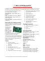
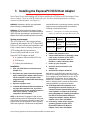
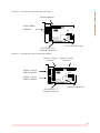
ATTO Technology, Inc. Installation and Operation Manual ATTO ExpressPCI Host Adapters Dual Channel Ultra3 (UL3D) Dual Channel Ultra3 66 MHz (UL3D-66) Single Channel Ultra3 (UL3S) Single Channel Ultra3 66 MHz (UL3S-66) © 2003 ATTO Technology, Inc. All rights reserved. All brand or product names are trademarks of their respective holders. No part of this manual may be reproduced in any form or by any means without the express written permission of ATTO Technology, Inc. 07/2003 Document Control Number: PRMA-0221-000MD Contents 1 What is ATTO ExpressPCI? ........................................................ 1 Plug and Play for PCI-based computers Features Operating Environments Power Requirements Environmental and Physical Specifications SCSI Bus 2 SCSI is a key technology for storage ......................................... 3 Glossary 3 Installing the ExpressPCI SCSI Host Adapter ........................... 5 System requirements Installation 3.1 Determining cabling and termination ................ 7 Cable types Examples Connectors Connection considerations Termination 3.2 Installing and Updating Device Drivers ............. 11 Windows Server 2003 & Windows 2000/XP Windows NT Installation Re-flashing Firmware in Windows Linux and Sun Solaris Driver Installation Updating Drivers and Re-flashing Firmware in Mac OS X Updating Drivers and Re-flashing Firmware in Mac OS 9 4 Maximizing Performance with your ExpressPCI HBA .............. 15 Use the latest ATTO driver Set registry for large block transfers Set up RAID groups with ATTO ExpressRAID Increase transfer size Analyze your I/Os 5 Troubleshooting ........................................................................... 17 Appendix A Standards and compliances ..................................... i Appendix B SCSI host adapter selection guide ........................... ii Appendix C Fibre Channel host adapter guide ............................ iii Appendix D Contact ATTO Technology, Inc. ............................... iv 1 What is ATTO ExpressPCI? Compatible with virtually all popular SCSI devices, ATTO ExpressPCI host adapters will increase the performance of disk-intensive applications such as digital video, prepress, multimedia and real-time. The ATTO ExpressPCI family of Ultra3 SCSI host adapters includes four models: ExpressPCI UL3S: Single Channel Ultra3, 33 Mhz PCI UL3D: Dual Channel Ultra3 SCSI, 33MHz PCI ExpressPCI UL3S-66: Single Channel Ultra3 SCSI, 66 MHz PCI ExpressPCI Ul3D-66: Dual Channel Ultra3 SCSI, 66 MHz PCI Plug and Play for PCI-based computers The ATTO ExpressPCI SCSI adapter uses plug and play technology to eliminate configuration manipulation, including setting termination for single-ended adapters. Insert the ATTO ExpressPCI SCSI adapter into your PCI-based computer and the adapter is configured according to your system. ATTO provides a variety of configuration tools if you need to alter the host adapter’s configuration. See the ATTO ExpressPCI Utilities manual for additional information. Features ❖ Automatic termination ❖ Advanced Data Streaming (ADS) ❖ ❖ ❖ ❖ ❖ Technology RAID ready Embedded RISC I/O processor Flash ROM BIOS for easy field upgrades PCI 2.1 Compliant Includes Mac® OS and PC Utility software ❖ Extensive device support: up to 105 through ❖ ❖ ❖ ❖ ❖ ❖ ❖ ❖ LUNs (Wide and Narrow devices) Advanced SCSI Large Command FIFO Supports disconnect/reconnect Asynchronous I/O support Multiple Initiator support SCSI-3 Tagged Command Queuing Low power requirements Mac SCSI Manager 4.3 and pre-4.3 compatible driver Operating Environments ❖ Windows 95/98, Windows NT/2000/XP ❖ Mac OS 9, Mac OS X ❖ Linux ❖ Sun Solaris Power Requirements UL3S/UL3S-66: 1.5 max Amps @ +5.0 VDC, 0.05 Amps @ +12.0 VDC, 7.5W UL3D/UL3D-66: 1.5 max Amps @ +5.0 VDC, 0.05 Amps @ +12.0 VDC, 15W Environmental and Physical Specifications Operating Temperature 0-50°C: Humidity 10-90% Non-condensing Length 6.521” Height 4.2” MTBF 150,000 hours MTTR < 15 minutes SCSI-3 connectors: UL3S/UL3S-66 external: (1) 68-pin VHDCI UL3S/UL3S-66 internal: (1) 68-pin Wide UL3D/UL3D-66 external: (2) 68-pin VHDCI UL3D/UL3D-66 internal: (2) 68-pin Wide 1 ATTO Technology ExpressPCI Ultra3 SCSI Host Adapters Installation and Operation Manual Maximum Host PCI transfer rate: 32-bit/33MHz: 133 MB/sec. 32-bit/66 Mhz: 266 MB/sec. 64-bit/33 Mhz: 266 MB/sec. 64-bit/66 Mhz: 532 MB/sec. Maximum SCSI transfer rate: Synchronous data rate (UL3D/UL3D-66): 60 MB/sec. per channel (Ultra3 mode) Asynchronous data rate:12 MB/sec. per channel (all models) SCSI-1, SCSI-2, SCSI-3, UltraSCSI, Ultra2SCSI, Ultra 160/m SCSI, Ultra3 SCSI Electrical Signals: single-ended, low voltage differential SCSI Interface: Introduction SCSI Bus Extensive device support: UL3D/UL3D-66: Up to 210 devices when used with LUNs (Wide and Narrow devices) UL3S/UL3S-66: Up to 210 devices when used with LUNs (Wide and Narrow devices) 2 2 SCSI is a key technology for storage SCSI is a serial communications technology designed to transfer large amounts of data between a variety of hardware systems over long distances. It is a key technology for applications that require shared, high bandwidth access to storage. SCSI provides a logical point-to point serial channel for the transfer of data between a buffer at a source device and a buffer at a destination device. It moves buffer contents from one port to another, without regard to the format or meaning of the data so different upper level protocols are able to run over SCSI hardware. The SCSI architecture is structured as a hierarchical set of protocol layers. Defined within these layers are rules for signal interfaces, serial encoding and decoding, error control, frame format and communications protocols. ATTO Express PCI SCSI host adapters carry SCSI protocol over SCSI. Glossary Some terms used in the SCSI industry are defined below. More information is available through the ATTO Technology website (www.attotech.com), and the SCSI Consortium (www.iol.unh.edu/consortium). Term Definition ANSI American National Standards Institute auto negotiation hardware senses and automatically responds depending on configuration BER Bit Error Rate: a measure of transmission accuracy; the ratio of bits received in error to bits sent bit Smallest unit of data a computer can process: a single binary digit with a value of either 0 or 1 byte an ordered set of 8 bits CRC Cyclic Redundancy Check: an error-correcting code which calculates a numeric value for received and transmitted data. If no error has occurred during transmission, the CRC for both received and transmitted data should be the same. host a processor, usually a CPU and memory, which communicates with devices over an interface initiator device A component which originates a command LED Light-emitting diode: a type of diode that emits light when current passes through it. Visible LEDs are used as indicator lights on all sorts of electronic devices. originator an initiating device; a component which originates a command receiver the ultimate destination of data transmission; a terminal device SCSI Small Computer Systems Interface: a processor-independent standard for system-level interface between a computer and intelligent devices including hard disks, floppy disks, CD-ROM, printers, scanners, etc. 3 ATTO Technology ExpressPCI Ultra3 SCSI Host Adapters Installation and Operation Manual Definition topology logical layout of the parts of a computer system or network and their interconnections transceiver a transmitter/receiver module transfer rate the rate at which bytes or bits are transferred, as in megabytes or gigabits per second. Glossary Term 4 3 Installing the ExpressPCI SCSI Host Adapter You will need a basic understanding of SCSI before installing the ATTO ExpressPCI host adapter. Please refer to Chapter 2 for a list of SCSI-related web sites. For more detailed explanations of cabling, connectors and termination, see Chapter 3.1. WARNING Remember to back up your system data before changing or installing hardware. WARNING ATTO ExpressPCI host adapters contain components that are sensitive to electrostatic discharge (ESD). ESD can cause damage to the ExpressPCI host adapter. Please follow standard methods to avoid ESD. System requirements The ATTO Express PCI host adapter package contains the host adapter, the ATTO ExpressPCI Utilities CD and a warranty and registration card. If any of these items are missing, contact your ATTO authorized sales representative. To successfully install and use your ATTO ExpressPCI SCSI adapter you need: card will still function in a 64-bit slot. However, removing jumpers may cause the ExpressPCI card to function incorrectly in some 32-bit PCI slots. Exhibit 3-1 Consequences of enabling and disabling jumpers J1 and J2 with an ExpressPCI 64-bit card. ExpressPCI 64-bit card JP1 and JP2 JP1 and JP2 disabled enabled 32-bit PCI slot Correct 32-bit May not function in operation some motherboards 64-bit PCI slot Correct 64-bit Correct 64-bit operation operation 5 Replace the computer cover. 6 Connect SCSI devices by inserting a SCSI cable to the connector on the ATTO ExpressPCI host adapter. Refer to Exhibit 3.1-2 when selecting cables. 7 Power up your computer. 8 Plan your SCSI device connections (see Chapter 3.1). Set SCSI device termination. (see Chapter 3.1) 9 Set SCSI IDs. Adapter default is 7. 2 Shut down the system and all peripherals before installing the adapter. After turning off the computer, leave the power cable plugged into a grounded outlet to discharge static electricity. 3 Open the computer case. Each device on the SCSI bus requires a unique SCSI ID. If installing a single device, make sure you do not assign it the same SCSI ID as your ATTO ExpressPCI SCSI adapter. Do not change the adapter ID if possible. For more information and ease in changing the ID, consult the ExpressPCI Utilities Installation and Operation Manual. 4 Install the ATTO ExpressPCI host adapter in ❖ A computer with an available PCI slot. ❖ SCSI devices ❖ Cable(s) and terminator(s). Installation 1 any open PCI expansion slot. If you have questions about how to install an expansion card in your system, consult your computer’s documentation. NOTE 64/32-bit Mode: The jumpers J1 and J2, when installed vertically, ensure ATTO ExpressPCI 64-bit cards work correctly in 32-bit mode in all 32-bit PCI slots. These jumpers do not force the ExpressPCI card to operate in 32-bit mode. If placed in a 64-bit mode, the ExpressPCI 10 ATTO ExpressPCI host adapters come preconfigured to operate properly in a variety of common system setups. However, some systems or setups may benefit by tuning the adapter for optimal performance. Use the ATTO ExpressPCI Utilities to change host adapter settings. Refer to Chapter 3.2 for more information. 11 If necessary, install drivers for your operating system from the ATTO ExpressPCI Utilities CD. Refer to Chapter 3.2 for more information. 5 ATTO Technology ExpressPCI Ultra3 SCSI Host Adapters Installation and Operation Manual The ATTO ExpressPCI UL3S/UL3S-66 adapter Hardware installation Exhibit 3-2 68-pin Connector 68-pin VHDCI Connector Ultra3 SCSI Processor 64/32-Bit PCI 2.2 Compliant Connector Exhibit 3-3 The ATTO ExpressPCI UL3D/UL3D-66 adapter Channel 1: 68-pin Connector Channel 2: 68-pin Connector Channel 2: 68-pin VHDCI Connector Channel 1: 68-pin VHDCI Connector Ultra3 SCSI Processor 64/32-Bit PCI 2.2 Compliant Connector 6 3.1 Determining cabling and termination Cables and devices must be chosen to maximize performance and minimize the electrical noise from the high-speed data transfers available with the SCSI protocol. Cabling and termination methods become important considerations for proper performance. SCSI cables and devices are subject to specific length and number limitations to deal with electrical problems that arise at increased operating speeds. ATTO ExpressPCI Ultra3 SCSI host adapters will operate with both Low Voltage Differential and Single-Ended devices. When connected to Ultra 3 devices, the ATTO ExpressPCI Ultra3 SCSI host adapters will negotiate to Ultra 3 transfer rates of 160 MB/sec. per channel. When connected to Single-Ended devices, the ATTO ExpressPCI Ultra3 SCSI host adapters will negotiate to Ultra3 transfer rates of 40 MB/sec. per channel. Cable types Single-ended and differential SCSI host adapters use the same cables. Use high quality cables rated for the type of SCSI transfers required: wellinsulated SCSI cables ensure error free communications. Try to keep cable lengths as short as possible to ensure higher signal quality and performance. Examples The SCSI specification limits total bus cable length for Single-Ended SCSI in a non-UltraSCSI environment to 3 meters (combined length of both internal and external cable lengths). In an UltraSCSI workgroup environment with a 7drive tower, you are limited to 1.5 meters between the host and the tower, including the cabling for the tower. If the 7-drive tower requires 1 meter of cabling to connect all of its drives, the distance from the tower to the host must be .5 meters. UltraSCSI is very sensitive to SCSI bus noise, cable distances and the number of devices connected on the SCSI bus. Carefully connect your devices when working with UltraSCSI. Ultra3SCSI and Ultra2 SCSI are less sensitive to bus noise and offer you the ability to connect a full load of devices up to 12 meters. Exhibit 3.1-1 Various types of SCSI require different bus lengths to support a certain number of devices. STA terms Bus speed Bus width Max. bus lengths, meters MB/sec. max. bits Single-ended Differential LVD Max. device support Fast SCSI 10 8 3 25 n/a 8 Fast/WIDE SCSI 20 16 3 25 n/a 16 UltraSCSI 20 8 1.5 25 n/a 8 UltraSCSI 20 8 3 n/a n/a 4 Ultra/WIDE SCSI 40 16 n/a 25 n/a 16 Ultra/WIDE SCSI 40 16 1.5 n/a n/a 8 Ultra/WIDE SCSI 40 16 3 n/a n/a 4 Ultra2 SCSI 80 16 n/a n/a 12 8 Ultra2/WIDE SCSI 80 16 n/a n/a 12 16 Ultra3/WIDE SCSI 160 16 n/a n/a 12 16 7 ATTO Technology ExpressPCI Ultra3 SCSI Host Adapters Installation and Operation Manual one industry standard 68-pin “P” (16-bit) cable connector for internal device connections and one 68-pin “P” (16-bit) VHDCI (Very High Density Cabled Interconnect) cable connector for external device connections. ATTO ExpressPCI UL3D/UL3D-66: two industry standard 68-pin “P” (16-bit) cable connectors for internal device connections and two 68-pin “P” (16-bit) VHDCI (Very High Density Cabled Interconnect) cable connectors for external device connections. ATTO ExpressPCI UL3S/UL3S-66: with your SCSI devices to determine if your device is Wide or Narrow. Cables and termination Connectors Exhibit 3.1-2 Several types of internal and external cable connectors. Connection considerations If using a combination of Wide 16-bit devices and Narrow 8-bit devices on the same connector, Wide devices must be connected first (closest to the connector), followed by the Narrow devices. Please refer to the documentation you received Termination The SCSI bus is a chain of SCSI devices. The devices at both ends of any SCSI chain must be terminated for the SCSI bus to function correctly. A SCSI device chain can be configured in three different ways: internal, external and an internal/external SCSI device chain. The ATTO ExpressPCI SCSI adapter is a SCSI device and may require termination depending upon the configuration. Be sure to use the correct terminator. Single-Ended, Low Voltage Differential and Differential SCSI busses use different types of terminators that should not be mixed. Single-Ended and LVD signaling The ExpressPCI Ultra3 SCSI host adapter supports two types of SCSI signaling: Low Voltage Differential (LVD) and Single-Ended. Ultra2 and Ultra3 SCSI require LVD signaling for optimal performance. UltraSCSI and slower devices use Single-Ended signaling. Devices on the same SCSI bus must use the same signaling, either LVD or Single-Ended. SCSI terminators used with Ultra3 SCSI host adapters must match the SCSI bus signal. When using only LVD devices an LVD terminator should be used. A Single-Ended terminator with LVD devices usually works, but all devices will be limited to Ultra SCSI speeds, instead of Ultra2 or Ultra3 speeds. Single-Ended devices require a Single-Ended terminator. If you use an LVD terminator with Single-Ended devices, the system may hang or devices will not be seen on the SCSI bus. Some termination manufacturers provide terminators which automatically sense Single-Ended or LVD termination. Internal and external termination External terminators should be attached to the last external device in the SCSI chain. Be careful not to provide any other termination on the external SCSI chain. (Extra termination will cause a loss in signal quality.) The last device on an internal SCSI chain should also be terminated. Many Single-Ended Ultra SCSI and earlier devices provide a jumper setting for applying termination, in which case the last device on the internal cable should have a Terminators 8 jumper placed over the pins designated for supplying termination. Check with your drive manufacturer if you are not sure which pins to use. LVD Ultra2 and Ultra3 SCSI devices are not capable of supplying their own termination. Instead, termination must be supplied by an outside source, usually an internal ribbon cable which has a SCSI terminator attached to the end. Connect the non-terminated end of the cable to the host adapter card and the internal drives to the subsequent connectors. The terminator should be at the opposite end of the cable from the host adapter card. Mixing Wide and Narrow devices Wide (16-bit) and Narrow (8-bit) devices can be connected together on the same connector of the host adapter card, but Wide devices must be attached first in the chain, followed by Narrow devices. The cable or adapter used to convert from a wide (68-pin) connector to a narrow (50-pin) connector must provide partial termination to allow the upper 8bits (or byte) of the Wide SCSI bus to be properly terminated. A Narrow terminator should then be used on the last Narrow device to terminate the rest of the SCSI bus. A SCSI bus without partial termination between the Wide and Narrow devices may appear to work correctly, but occasional I/O errors will occur without proper termination. Using internal and external connectors on UL3D/UL3D-66 The UL3D/UL3D-66 has two connector and an external connector. Devices can be attached to both connectors on the same bus. However, the host adapter card will run with Single-Ended signaling at UltraSCSI speeds if Single-Ended and LVD devices are on the same bus, even if using different connectors. Automatic termination: when both internal and external connectors are used, the host adapter card detects the presence of devices and turns off termination. If devices are removed from one connector of the card, the host adapter will automatically detect the change and enable its own termination. Software controlled termination: You may have to override the host adapter’s automatic termination if only narrow devices are attached to one connector and wide devices are attached to the other connector on the same bus. The host adapter must supply partial termination to the upper 8-bits (byte), but it will not do so automatically. Please refer to your ExpressPCI Utilities manual to set the host adapter’s termination to Upper Byte. Termination power: host adapters supply termination power to the bus at all times and many SCSI devices are also able to supply termination power. SCSI signal quality, particularly with long or marginal quality cables, may be improved if the device supplies the termination power. Contact your device manufacturer for more information on your device’s ability to supply termination power. connectors on each SCSI bus, an internal 9 ATTO Technology ExpressPCI Ultra/WIDE SCSI Host Adapters Installation and Operation Manual Cables and termination 10 3.2 Installing and Updating Device Drivers After installing the ATTO ExpressPCI host adapter, you must configure your system to recognize and use it by installing drivers for your operating system. If you already have one or more ExpressPCI adapters installed and you are installing additional adapter(s), you do NOT need to perform any of these procedures unless you are updating a previously installed driver. Windows Server 2003 & Windows 2000/XP channel. Proceed through the wizard with the default settings to complete the installation. To install or upgrade the ExpressPCI driver 1 2 3 4 5 Log on to Windows as the system administrator. Insert your ExpressPCI Installation Disk Run Setup.exe Click Install Follow the instructions to complete the installation. To add drivers to an existing Windows installation if you are NOT replacing the adapter to which the boot disk drive is attached. NOTE Complete this installation procedure before attaching any devices to the adapter. If another driver has been loaded before the ExpressPCI driver is loaded and you are using ATTO striping, you may experience data corruption. 1 Log on to Windows as the system administrator. 2 Insert your ExpressPCI Installation Disk 3 Run Setup.exe 4 Click Install 5 Follow the instructions to complete the installation. 6 Shut down Windows when the Setup window prompts you to do so. 7 Install your ExpressPCI adapter into an available PCI expansion slot. 8 Restart Windows. Windows should detect your ExpressPCI adapter. 9 Windows Server 2003/XP: Insert the ExpressPCI Installation disk when prompted............................................................... Windows 2000: The Found New Hardware Wizard will appear: proceed through the wizard defaults and insert the ExpressPCI Installation disk when prompted. 10 When adapter installation is complete, the Found New Hardware Wizard will appear showing an ATTO Phantom Device for each To add support to an existing Windows installation if you ARE replacing the adapter to which the boot disk drive is attached 1 2 3 4 5 6 7 8 Log on to Windows as the system administrator. Insert your ExpressPCI Installation Disk Run Setup.exe Click Install Follow the instructions to complete the installation Leaving the existing adapter in the system with the devices attached, shut down Windows Attach the desired devices from your previous adapter to the ExpressPCI adapter and, if desired, remove the previous adapter. Restart Windows. To install a new copy of Windows onto a SCSI disk attached to the ExpressPCI adapter. 1 2 3 4 5 6 7 8 Start Windows text mode setup as per the instructions provided with Windows. When the first blue window, Windows Setup, appears, press F6. The setup program will display a prompt in the status window on the bottom left of the monitor. Setup will continue to load files At the new window with instructions to specify additional mass storage devices, press S. Insert the ExpressPCI installation disk in drive A: and press Enter. At the screen from which you would normally select a driver, a list of ExpressPCI adapters should appear. Select your adapter and press Enter. Windows Setup will load the files from the disk. ATTO ExpressPCI device should now be listed as detected in the screen which appears. Repeat steps 3-7 for any other vendor-supplied driver installation disks. 11 ATTO Technology ExpressPCI Ultra/WIDE SCSI Host Adapters Installation and Operation Manual After all other drivers have been processed, press Enter and proceed with the rest of the Windows Installation procedure. NOTE When Windows begins copying files to your hard disk, you will again be prompted to insert the ExpressPCI installation disk and any other vendor-supplied disks you used during custom installation. This is normal. The first time you inserted the disks, Windows loaded the drivers into memory; the second time, Windows copied the driver to the hard disk. Windows NT Installation To install/upgrade the Windows NT driver 1 Log on to Windows as the system administrator. 2 Open the SCSI Adapters applet in the Control Panel 3 Click on Drivers tab. 4 Click Add... 5 Click Have Disk... 6 Insert your ExpressPCI Installation Disk 7 Enter the path for it under Copy manufacturer’s files from 8 Click OK 9 A list of ExpressPCI adapters will be displayed. Select your adapter and click OK. 10 Windows will install the necessary files and prompt you to restart Windows. 11 Restart Windows to complete the ExpressPCI installation. 12 Restart Windows to complete the ExpressPCI installation. To add a driver for your ExpressPCI adapter to an existing Windows installation if you ARE replacing the adapter to which the boot disk drive is attached 1 2 3 4 5 6 7 8 To add a driver to an existing Windows installation when you are NOT replacing the adapter to which the boot disk drive is attached. 9 10 1 11 Install the ExpressPCI adapter into an available PCI expansion slot. 2 Log on to Windows as the system administrator. 3 Open the SCSI Adapters applet in the Control Panel 4 Click on Drivers tab. 5 Click Add... 6 Click Have Disk... 7 Insert your ExpressPCI Installation Disk 8 Enter the path for it under Copy manufacturer’s files from 9 Click OK 10 A list of ExpressPCI adapters will be displayed. Select your adapter and click OK 11 Windows will install the necessary files and prompt you to restart Windows. 12 13 14 15 Insert the adapter into an available PCI expansion slot, but DO NOT remove the existing adapter or disconnect devices from it. Log on to Windows as the system administrator. Open the SCSI Adapters applet in the Control Panel Click on Drivers tab. Click Add... Click Have Disk... Insert your ExpressPCI Installation Disk Enter the path for it under Copy manufacturer’s files from Click OK A list of ExpressPCI adapters will be displayed. Select your adapter and click OK Windows will install the necessary files and prompt you to restart Windows. Restart Windows to complete the ExpressPCI installation. Shut down Windows, attach the desired devices from your previous adapter to the ExpressPCI adapter and, if desired, remove the previous adapter. Restart Windows. If you removed the previous adapter, you will see messages stating that one or more services did not start, suggesting that you look in the system log. To avoid receiving these messages on subsequent system startup attempts, use the SCSI Adapters applet in the Control Panel to remove the driver for the previous adapter. 12 Install, update drivers 9 To install a new copy of Windows NT onto a SCSI disk attached to your ExpressPCI adapter. 1 2 3 4 5 6 Start Windows NT text mode setup as per the instructions provided with Windows NT. Press F6 when the first blue window, Windows NT Setup, appears. Setup will continue to load files. After loading the setup files, you will be given several choices. Press Enter to install Windows. From the list of devices detected by Windows, press S. Choose Other to install the ExpressPCI driver and any other drivers for which you have OEMsupplied installation disks. Insert the ExpressPCI installation diskette in drive A: 7 8 Press Enter Windows should load the driver, detect the presence of the ExpressPCI adapter, then return to the screen of step 3. The ExpressPCI driver should now be included in the list of devices. Repeat steps 3 - 8 for any other vendor-supplied driver installation disks. 9 After all other drivers have been processed, press Enter and proceed with the rest of the Windows Installation procedure. NOTE When Windows begins copying files to your hard disk, you will be prompted to insert the ExpressPCI installation disk and any other vendor-supplied disks you used during custom installation. This is normal. The first time you inserted the disks, Windows loaded the drivers into memory; the second time, Windows copied the driver to the hard disk. Re-flashing Firmware in Windows ATTO typically releases adapter firmware and drivers simultaneously. We recommend that both the firmware and drivers be updated to ensure proper operation. 6 Follow the on-line instructions. 7 Remove the disk and reboot the PC. NOTE Firmware must be loaded from a floppy or from the internal hard drive because the CD-ROM drivers are not loaded at this point in the system boot process. To re-flash the firmware to the latest version: To re-flash the firmware to the latest version for Ultra320 adapters: The ATTO ExpressPCI Configuration Tool, available on the ATTO web site, www.attotech.com/software/index.html, will verify drivers and firmware versions and attempt to flash. Instructions for using this utility are provided as part of the download process. 1 2 3 4 5 Obtain the latest firmware from the ATTO web site www.attotech.com. Extract the firmware to a floppy disk by executing the self-extracting file. Reboot the PC. An ATTO Technology banner will announce that the host adapter was detected. Enter Control-Z when prompted to begin the setup utility. Select the Upgrade Flash ROM option and insert the disk into the drive slot. Linux and Sun Solaris Driver Installation ATTO offers Linux and Sun Solaris drivers which are compatible with the ExpressPCI host adapters. A complete download package, including all necessary installation instructions, is available on the ExpressPCI Utilities CD-ROM or directly from the ATTO Technology web site, www.attotech.com. Please refer to these documents for installation instructions. Updating Drivers and Re-flashing Firmware in Mac OS X Mac OS X drivers, including installer packages, can be downloaded directly from the ATTO web site, www.attotech.com. The driver installers will automatically unionist existing drivers and properly install the new drivers on your system. After installing, the new adapter driver you will need to update the firmware. 13 TTO Technology ExpressPCI Ultra3 SCSI Host Adapters Installation and Operation Manual verify drivers and firmware versions and attempt to flash. Instructions for using this utility are provided as part of the download process. Updating Drivers and Re-flashing Firmware in Mac OS 9 To re-flash the firmware to the latest version: 1 2 3 Obtain the latest firmware and updater program from the ATTO web site www.attotech.com and download to your host. Create a folder or drive where you want the program files to be placed. Using a compression utility capable of handling hqx files, extract the files by clicking Save. 4 5 6 7 8 Open the program file folder and click on the ExpressPCI Updater program. Select the appropriate option and hit Enter. A message will inform you which ExpressPCI cards were updated. Type Q to quit. Re-boot the Macintosh system. 14 Install, update drivers The ATTO ExpressPCI Configuration Tool, available on the ATTO web site, www.attotech.com/software/index.html, will 4 Maximizing Performance with ExpressPCI HBA If you are getting less performance than you expect, there are several things you can do such as making sure you are using the latest ATTO driver, setting the registry entry for large block transfers, using ATTO ExpressRAID for setting up RAID groups, increasing transfer size, and analyzing your system’s I/Os. While the factory settings on your ExpressPCI host adapter should provide excellent performance for a wide range of applications, you may improve performance by modifying some of the system factors which affect your ExpressPCI host adapter. For example, the ATTO driver can transfer well over a megabyte with one SCSI command. NOTE You must use an ATTO driver when using ATTO ExpressRAID software. Use the latest ATTO driver Determine which drive is currently in use, then install the latest ATTO driver found at www.attotech.com. Windows NT 1 Open My Computer 2 Open Control Panel 3 Open SCSI Adapters 4 Examine the Driver tab for your SCSI adapter. If the driver is not express.sys, install the express.sys driver. 5 Either remove the previously-installed driver or disable it using the Devices applet. If the system has a built in Symbios or LSI adapter, do not disable the driver for that adapter. Windows 2000 and XP 1 Using the Device Manager, select SCSI & RAID Controllers 2 Examine the Driver tab for your SCSI adapter. If the driver is not express.sys, install the express.sys driver. 3 Either remove the previously-installed driver or disable it using the Devices applet. If the system has a built in Symbios or LSI adapter, do not disable the driver for that adapter. Set registry for large block transfers If your application requires large block transfers, set the registry entry correctly for the MaximumSGList keyword. Several files supplied with the device driver download package can set this value to any one of the following sizes: 64Kb, 128KB, 256Kb, 512KB, 1MB and NT default (64KB). The files are ASCII text files and can be viewed with any suitable editor. The files also explain the registry setting and how to change the setting. The ExpressPCI adapter can have a maximum transfer size from 64KB to 1MB. If the registry value is set to a number higher than 0xff, the driver will reduce the setting to 0xff. The driver installation process will set the default value to 0xff. Set up RAID groups with ATTO ExpressRAID Instead of using the RAID functionality built into Windows OS, use the ATTO ExpressRAID software for the most efficient performance. ATTO ExpressRAID requires one less level of driver through which commands must pass and fewer commands are required to pass through the driver hierarchy. Other advantages of ATTO ExpressRAID striping: ❖ You can boot your system off striped drives ❖ Stripe sets created with ExpressRAID are recognizable by DOS and Windows ❖ You can stripe removable-media drives with ExpressRAID. If you have purchased the striping option, additional information about ExpressRAID is 15 TTO Technology ExpressPCI Ultra3 SCSI Host Adapters Installation and Operation Manual Increase transfer size If you are writing to an application that uses a lot of sequential disk I/O to a contiguous area on disk, you should use as large a transfer size as possible to reduce overhead on the system, on the SCSI bus and within disk drives. Analyze your I/Os For large sequential data transfers, use Direct I/O by selecting FILE_FLAG_WRITE_THROUGH and FILE_FLAG_NO_BUFFERING flags with your CreateFile call to avoid the overhead of copying data from one area of memory to another, to reduce the number of SCSI commands which must be executed and to leave system pages available for other data. If your application requires a small number of I/Os and the transfers are rather small, however, you may get better performance by letting the system cache your data in the system pages. You might want to use over-lapped I/O using the FILE_FLAG_OVERLAPPED option with the CreateFile call. Overlapped I/O allows the application to send many commands to the device at once. The ATTO Disk Benchmark program, included with the ExpressPCI Utilities on the CD shipped with your ExpressPCI adapter, shows the effect of using the above I/O modes. ❖ If you turn off Direct I/O and set the file size to a value significantly less than the amount of memory in your computer, you will get some artificially high transfer rates because very little I/O is actually being performed by the SCSI device: all the activity is involved in transferring data between the application and the system pages. ❖ As you increase the file size to a value more than the amount of memory in your computer, you will see marked performance degradation. ❖ If you turn on Direct I/O, you can see the effect of removing the system pages from the overhead picture. ❖ If you use overlapped I/O, you will see performance improvements in the low to medium transfer sizes. ❖ However, depending on the amount of memory in your computer, you may not be able to use queue depths greater than 4 or 5. 16 Maximize performance available in the file Stripe.txt on the CD which has been included with your ATTO ExpressPCI adapters. 5 Troubleshooting This chapter contains solutions for the most common problems you might encounter. If you need additional assistance, please refer to the ATTO Technology web site (www.attotech.com) or contact an ATTO Technology authorized representative. 9Check each cable connection on every device. Verify all cables are in proper working condition. Loose or broken cables are often the cause of errors or problems. 9If the same device shows up at several different SCSI IDs, either its SCSI ID is set the same as the ATTO ExpressPCI SCSI ID, or the cable is defective. 9Check that your SCSI devices are plugged into an AC outlet and are turned on before you add power to your computer. 9If a device doesn’t appear and cables and termination are set properly, try lengthening the SCSI Reset Delay using the ExpressPCI Utilities found on the CD that came with your host adapter. 9Verity that all devices and busses are properly terminated. See Chapter 3.1 for more information. 9Verify that all devices attached to the ATTO ExpressPCI SCSI adapter have unique SCSI IDs. ATTO ExpressPCI SCSI adapters have a default SCSI ID of 7. 9PC users should make sure that SCSI adapter firmware and Windows drivers are at the same revision level. Unless indicated otherwise, the latest drivers and firmware can be downloaded from the ATTO Technology website (www.attotech.com) 17 ATTO Technology ExpressPCI Ultra3 SCSI Host Adapters Installation and Operation Manual Troubleshooting 18 Appendix A Standards and compliances The equipment described in this manual generates and uses radio frequency energy. The Technical Specification sheet for a particular ATTO ExpressPCI host bus adapter list certifications for that model. FCC standards: radio and television interference WARNING This equipment has been tested and found to comply with the limits for a Class A digital device, pursuant to Part 15 of the FCC Rules. These limits are designed to provide reasonable protection against harmful interference in a residential installation. This equipment generates, uses, and can radiate radio frequency energy and, if not installed and used in accordance with the instruction manual, may cause interference to radio communications. However, there is no guarantee that interference will not occur in a particular installation. If this equipment does cause interference to radio or television reception, which can be determined by turning the equipment off and on, the user is encouraged to try to correct the interference by one or more of the following measures: ❖ Reorient or relocate the receiving antenna ❖ Increase the separation between the equipment and receiver ❖ Connect the equipment into an outlet on a circuit different from that to which the receiver is connected ❖ Consult the dealer or an experienced radio/TV technician for help Canadian standards This Class A digital apparatus complies with Canadian ICES-003. Cet appareil numérique de la classe A est conforme à la norme NMB-003 du Canada. European standards Declaration of Conformity This following statement applies to the ATTO Express PCI host bus adapter. This device has been tested in the basic operating configuration and found to be compliant with the following European Union standards: Application of Council Directive: 89/336/EEC Standard(s) to which conformity is declared: EN55024:1998 This Declaration will only be valid when this product is used in conjunction with other CE approved devices and when the entire system is tested to the applicable CE standards and found to be compliant. C-Tick This apparatus meets all requirements for C-Tick Certification. i ATTO Technology ExpressPCI Ultra3 SCSI Host Adapters Installation and Operation Manual Appendix B SCSI host adapter selection guide ATTO Technology offers a number of SCSI and Fibre Channel solutions for storage. The following chart compares the features of ExpressPCI SCSI host adapters. Supported platforms: Sun Solaris; Linux; NetWare; SCO Unix; Windows 2000, 95/98, NT, and Macintosh OS and OS X. Complete RAID packages are also available and include an ExpressPCI SCSI host adapter, ExpressRAID software and appropriate cable(s). Add "-KIT" suffix to host adapter product code (i.e. EPCI-UL3D-KIT) Specific features Single Channel ExpressPCI Ultra 320 Express PCI Ultra 3 Express PCI Ultra Wide 320 MB/sec 160 MB/sec. 40 MB/sec. 64-bit 32-bit 33/66 MHZ 133 MHZ Bus ID support 30 30 15 EPCI-UL4S EPCI-UL3S EPCI-PSC Max. transfer rate LVD HVD Part number Dual Channel--- 2 ExpressPCI Ultra 320 independent channels Max. transfer rate Express PCI Ultra 3 640 MB/sec 320 MB/sec. LVD 64-bit 32-bit 33/66 MHZ 133 MHZ Bus ID support 30 30 EPCI-UL4S EPCI-UL3D Part number ii Appendix C Fibre Channel host adapter guide ATTO Technology offers a number of SCSI and Fibre Channel solutions for storage. The following chart compares the features of ExpressPCI Fibre Channel host adapters. Supported platforms: Sun Solaris; Linux; NetWare; SCO Unix; Windows 2000, 95/98, NT, and Macintosh OS and OS X. Complete RAID packages are also available and include an ExpressPCI SCSI host adapter, ExpressRAID software and appropriate cable(s). Add "-KIT" suffix to host adapter product code (i.e. EPCI-UL3D-KIT) ExpressPCI Express PCI ExpressPCI ExpressPCI Express PCI FCSW FC 2600 FC 3300 FC 3321 FC 3305 Fibre Channel ports Optical interface 1 1 Fixed SW SC Copper interface 1 2 Fixed SW LC Fixed SW LC HSSDC 1 HSSDC Max. transfer rate 200 MB/sec. full duplex 200 MB/sec. full duplex 400 MB/sec. full duplex 400 MB/sec. per channel full duplex 400 MB/sec. full duplex Class 2 transfers 7 7 7 7 7 7 7 7 7 7 7 7 7 7 7 7 7 7 7 7 64- and 32-bit PCI support 7 7 7 7 7 Windows® XP/2000/NT; Windows 95/98; Linux and Macintosh® OS, OS X 7 7 7 7 7 RAID support 7 7 7 7 7 500 m 25 m (175 m with MIA) 500 m 500 m 25 m (175 m with MIA) EPCI-FCSW-000 EPCI-2600-000 EPCI-3300-000 EPCI-3321-000 EPCI-3305-000 Class 3 transfers Full duplex 66 MHz backward compatible with 33 MHz Max. cable length Part number Complete RAID packages are also available. To receive the ATTO ExpressPCI host adapter, ExpressRAID software and appropriate cable(s), add “-KIT” to host adapter product code (i.e., EPCI-2600-000-KIT) when ordering. iii ATTO Technology ExpressPCI Ultra3 SCSI Host Adapters Installation and Operation Manual Appendix D Contact ATTO Technology, Inc. Customer service, sales information and technical support are available by phone Monday through Friday, Eastern Standard Time 8:00 a.m. to 8:00 p.m., or by e-mail and web site 24-hours a day. ATTO Technology, Inc. 155 CrossPoint Parkway Amherst, New York 14068 (716) 691-1999 • voice (716) 691-9353 • fax http://www.attotech.com ATTO Technology can also be reached via e-mail at the following addresses: Sales Support: [email protected] Technical Support: [email protected] iv