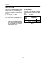
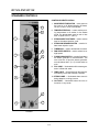
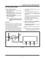
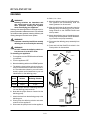
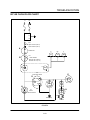
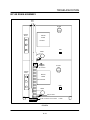
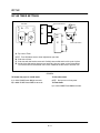
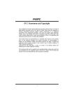
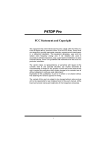
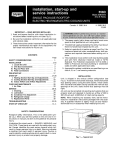
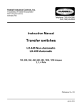
1
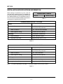
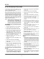
BC14E AND BC14G
COMBINATION OVEN STEAMER
SERVICE AND REPAIR MANUAL
BLODGETT COMBI
www.blodgett.com
50 Lakeside Avenue, Box 586, Burlington, Vermont 05402 USA Telephone (800) 331-5842, (802) 860-3700 Fax: (802)864-0183
PN R10251 Rev A (1/02)
E 2002 --- Blodgett Combi
TABLE OF CONTENTS
Section 1
BC14G Installation
Installation Specifications/Information . . . . . . . . . . . . . . . . . . . . . . . . . . . . . . . . . .
Oven Location . . . . . . . . . . . . . . . . . . . . . . . . . . . . . . . . . . . . . . . . . . . . . . . . . . . . . .
Stacking . . . . . . . . . . . . . . . . . . . . . . . . . . . . . . . . . . . . . . . . . . . . . . . . . . . . . . . . . . .
Plumbing Connections . . . . . . . . . . . . . . . . . . . . . . . . . . . . . . . . . . . . . . . . . . . . . . .
Door Adjustments . . . . . . . . . . . . . . . . . . . . . . . . . . . . . . . . . . . . . . . . . . . . . . . . . . .
Section 2
Operation and Maintenance
Standard Controls . . . . . . . . . . . . . . . . . . . . . . . . . . . . . . . . . . . . . . . . . . . . . . . . . . .
Optional Meat Probe . . . . . . . . . . . . . . . . . . . . . . . . . . . . . . . . . . . . . . . . . . . . . . . . .
Deliming . . . . . . . . . . . . . . . . . . . . . . . . . . . . . . . . . . . . . . . . . . . . . . . . . . . . . . . . . . .
Section 3
5---1
Component Identification
Component Identification . . . . . . . . . . . . . . . . . . . . . . . . . . . . . . . . . . . . . . . . . . . . .
Component Location Diagrams . . . . . . . . . . . . . . . . . . . . . . . . . . . . . . . . . . . . . . .
Section 7
4---1
4---2
Pre-Site Visit Questions
Troubleshooting Sequence . . . . . . . . . . . . . . . . . . . . . . . . . . . . . . . . . . . . . . . . . . .
Section 6
3---1
3---3
3---4
3---5
3---6
3---7
3---8
3---9
3---10
3---11
3---12
BC14G Schematics
BC14G . . . . . . . . . . . . . . . . . . . . . . . . . . . . . . . . . . . . . . . . . . . . . . . . . . . . . . . . . . . . .
BC14G for CE . . . . . . . . . . . . . . . . . . . . . . . . . . . . . . . . . . . . . . . . . . . . . . . . . . . . . .
Section 5
2---1
2---2
2---3
BC14G Troubleshooting
BC14G Troubleshooting Guide . . . . . . . . . . . . . . . . . . . . . . . . . . . . . . . . . . . . . . . .
BC14G Incoming Power Check . . . . . . . . . . . . . . . . . . . . . . . . . . . . . . . . . . . . . . .
BC14G Hot Air Flow Chart . . . . . . . . . . . . . . . . . . . . . . . . . . . . . . . . . . . . . . . . . . . .
BC14G Steam Flow Chart/Water Fill . . . . . . . . . . . . . . . . . . . . . . . . . . . . . . . . . . .
BC14G Combi Flow Chart . . . . . . . . . . . . . . . . . . . . . . . . . . . . . . . . . . . . . . . . . . . .
BC14G On Demand Steam Flow Chart . . . . . . . . . . . . . . . . . . . . . . . . . . . . . . . . .
BC14G Flush Flow Chart . . . . . . . . . . . . . . . . . . . . . . . . . . . . . . . . . . . . . . . . . . . . .
BC14G Water Fill/Meat Probe/condensate/cooling fan . . . . . . . . . . . . . . . . . . .
BC14G Drain Assembly . . . . . . . . . . . . . . . . . . . . . . . . . . . . . . . . . . . . . . . . . . . . . .
BC14G Flue Assembly . . . . . . . . . . . . . . . . . . . . . . . . . . . . . . . . . . . . . . . . . . . . . . .
BC14G Timer Settings . . . . . . . . . . . . . . . . . . . . . . . . . . . . . . . . . . . . . . . . . . . . . . .
Section 4
1---1
1---3
1---4
1---5
1---6
6---1
6---5
BC14E Schematics
BC14E . . . . . . . . . . . . . . . . . . . . . . . . . . . . . . . . . . . . . . . . . . . . . . . . . . . . . . . . . . . . .
BC14E for CE . . . . . . . . . . . . . . . . . . . . . . . . . . . . . . . . . . . . . . . . . . . . . . . . . . . . . . .
7---1
7---2
TABLE OF CONTENTS
Section 8
BC14E Troubleshooting
BC14E Troubleshooting Guide . . . . . . . . . . . . . . . . . . . . . . . . . . . . . . . . . . . . . . . .
BC14E Safety Limits Flow Chart . . . . . . . . . . . . . . . . . . . . . . . . . . . . . . . . . . . . . . .
BC14E Hot Air Flow Chart . . . . . . . . . . . . . . . . . . . . . . . . . . . . . . . . . . . . . . . . . . . .
BC14E Steam Flow Chart . . . . . . . . . . . . . . . . . . . . . . . . . . . . . . . . . . . . . . . . . . . .
BC14E Combi Flow Chart . . . . . . . . . . . . . . . . . . . . . . . . . . . . . . . . . . . . . . . . . . . .
BC14E On Demand Flow Chart . . . . . . . . . . . . . . . . . . . . . . . . . . . . . . . . . . . . . . .
BC14E Flush Flow Chart . . . . . . . . . . . . . . . . . . . . . . . . . . . . . . . . . . . . . . . . . . . . .
BC14E Water Fill/Meat Probe . . . . . . . . . . . . . . . . . . . . . . . . . . . . . . . . . . . . . . . . .
BC14E Drain Assembly . . . . . . . . . . . . . . . . . . . . . . . . . . . . . . . . . . . . . . . . . . . . . .
BC14E Timer Settings . . . . . . . . . . . . . . . . . . . . . . . . . . . . . . . . . . . . . . . . . . . . . . .
Section 9
8---1
8---3
8---4
8---5
8---6
8---7
8---8
8---9
8---10
8---11
BC14E Installation
Installation Specifications . . . . . . . . . . . . . . . . . . . . . . . . . . . . . . . . . . . . . . . . . . . . .
Oven Location and Leveling . . . . . . . . . . . . . . . . . . . . . . . . . . . . . . . . . . . . . . . . . .
Stacking . . . . . . . . . . . . . . . . . . . . . . . . . . . . . . . . . . . . . . . . . . . . . . . . . . . . . . . . . . .
Plumbing Connections . . . . . . . . . . . . . . . . . . . . . . . . . . . . . . . . . . . . . . . . . . . . . . .
Door Adjustments . . . . . . . . . . . . . . . . . . . . . . . . . . . . . . . . . . . . . . . . . . . . . . . . . . .
9---1
9---2
9---3
9---4
9---5
CHAPTER 1
BC14G INSTALLATION
BC14G
INSTALLATION SPECIFICATIONS/INFORMATION
Before starting to troubleshoot an oven, verify the
oven has been installed correctly. The installation of
the electric and gas connections must be performed
by a qualified installer only. The installation must conform to all local and national installation standards. A
hood system is required with the BC14G.
MAXIMUM SHELF LOADING
BC14G
100 lbs (45.5 Kg)
TABLE 1
PLUMBING SPECIFICATIONS -- BC14G/AA
Water
Water Pressure
30 PSI (207 kPa) minimum
50 PSI (345 kPa) maximum
Water Connection
3/4” Hose Hot and Cold Water
Water Regulator Setting
Preset to 20 PSI (138 kPa)
Drainage
Atmospheric Vented Drain
Drain Connection
2.00” (50.8mm) Copper
Avg Water Drain Temp.
Approximately 160_F (71_C)
TABLE 2
PLUMBING SPECIFICATIONS -- BC14GDS/AA
Water
Water Pressure
30 PSI (207 kPa) minimum
50 PSI (345 kPa) maximum
Water Connection
3/4” Hose Cold Water
Water Regulator Setting
Preset to 20 PSI (138 kPa)
Drainage
Atmospheric Vented Drain
Drain Connection
2.00” (50.8mm) Copper
Avg Water Drain Temp.
Approximately 160_F (71_C)
NOTE: For steam requirements see page 1 ---5 STEAM CONNECTION for the BC14GDS.
TABLE 3
1---1
INSTALLATION
RATINGS -- GAS APPLIANCES -- BC14G/AA
Gas Type
Gas Input
Voltage
Phase
Amps
Motor
Natural
Steam --- 55,000 BTU/Hr
Hot Air --- 65,000
65 000 BTU/Hr
Total --- 115,000 BTU/Hr
208-240
1
15
1/2HP 208-240VAC, 50/60 Hz
120
1
15
1/2HP 208-240VAC, 50/60 Hz
Steam --- 48,000 BTU/Hr
Hot Air --- 65,000
65 000 BTU/Hr
Total --- 113,000 BTU/Hr
208-240
1
15
1/2HP 208-240VAC, 50/60 Hz
120
1
15
1/2HP 208-240VAC, 50/60 Hz
Propane
3/4” FNPT connector for all U.S. and Canadian installations
TABLE 4
RATINGS -- GAS APPLIANCES -- BC14GDS/AA
Gas Type
Gas Input
Voltage
Phase
Amps
Motor
Natural
65,000 BTU/Hr
208-240
1
15
1/2HP 208-240VAC, 50/60 Hz
120
1
15
1/2HP 208-240VAC, 50/60 Hz
208-240
1
15
1/2HP 208-240VAC, 50/60 Hz
120
1
15
1/2HP 208-240VAC, 50/60 Hz
Propane
65,000 BTU/Hr
3/4” FNPT connector for all U.S. and Canadian installations
TABLE 5
GAS PRESSURE -- BC14G/AA and BC14GDS/AA
Gas
Type
T
Natural
Propane
Inlet
Pressure
P
Orifice Size at Sea Level
Manifold Pressure
Hot Air
Steam
Hot Air
Steam
7---14” W.C.
.0531” dia
.042” dia
3.5” W.C.
3.5” W.C.
12---14” W.C.
.032” dia
.026” dia
10.0” W.C.
10.0” W.C.
TABLE 6
1---2
BC14G
OVEN LOCATION
Left Side Heat Shield
Certain minimum clearances must be maintained
between the oven and any combustible or noncombustible construction. See the following table.
Heat sources should not be near the air vents located on the left hand side of the gas appliance.
Consult the factory for optional protective side heat
shield.
The following clearances are recommended for
servicing.
D
Oven body sides --- 12” (30cm)
D
Oven body back --- 12” (30cm)
BC14G
NOTE: On gas models, routine servicing can usually be accomplished within the limited
movement provided by the gas hose restraint. If the oven needs to be moved further from the wall, the gas must first be
turned off and disconnected from the oven
before removing the restraint. Reconnect
the restraint after the oven has been returned to its normal position.
Oven
M d l
Model
BC14G
P/N R9527
MINIMUM REQUIRED
CLEARANCES
Right Side
1”
(25.4mm)
Left Side
6”
6”
(152.4mm) (152.4mm)
TABLE 7
1---3
Back
INSTALLATION
STACKING
4. Bolt the two appliances together using the
bolts provided.
WARNING!!
Stacking should be performed by qualified installation personnel only. The appliances are heavy. Take care to use proper tools and techniques when lifting and
stacking appliances.
5. Attach the flue vents as shown.
6. Replace the drip pan.
7. Connect the drain, gas (if applicable) electrical
and water. Refer to page 1---5.
1. Remove the drip pan from the top appliance.
NOTE: An optional gas plumbing manifold may be
purchased from Blodgett Combi. Order
part number R9570. An optional drain
plumbing manifold may be purchased
from Blodgett Combi. Order part number
R9381 for single or top ovens.
2. Attach the legs or casters to the bottom appliance.
3. Place the top appliance on the bottom appliance. Be sure all four sides are flush.
Steam Vent
Assembly
Option
Hot Air
Flue
Steam
Generator
Flue
Drip Pan
Rear View
1.125” I.D. Hose
from Drip Pan Drain
FIGURE 1
1---4
BC14G
PLUMBING CONNECTIONS
WATER CONNECTION
DRAIN CONNECTION
Connect the appliance to quality water (refer to
specs below) via a pressure hose with 3/4” (19mm)
couplings. The water pressure needs to be between 30 psi (min) and 50 psi (max). All ovens are
supplied with a water manifold which allows for
one, cold water only connection to the oven. This
water connector must have a brass water restrictor
attached to it, which is part of the manifold assembly. Should a customer wish to supply treated water to the steam generator, a kit can be added to the
oven which supplies a plug for the water manifold
and a separate water flow restrictor.
The waste drain assembly must be constructed of
2-inch copper and be atmospherically vented. The
venting must have a riser so the steam vents above
the top of the oven. In a stacked oven configuration, the venting on the bottom oven must vent
above the top oven. It is recommended that separate drain lines be run on stacked ovens. Refer to
FIGURE 3 for a recommeded water drain configuration.
Vents
Steam
Water must meet the following minimum requirements:
D
D
Total Dissolved Solids (TDS) content will not
exceed 30 parts per million.
Water PH must be 7.0 or higher.
WARNING!!
Operating the appliance without the water
restrictor installed will invalidate the warranty. The use of poor quality water will invalidate the warranty.
Hot Water
Drains
FIGURE 3
STEAM CONNECTION FOR BC14GDS
Cold Water
Option 1
Steam supply line is 3/4” NPT. Steam must be clean,
dry and potable. A particle screen and bucket trap
may be needed and are recommended. 60 lbs per
hour is the maximum usage per oven. Steam supply
pressure should not exceed 40 to 50 psi. The flow
pressure is 1-1/2 to 3-1/2 psi and is set at the steam
pressure regulator supplied inside the oven.
Cold Water
Option 2
Water Connections Rear of Appliance
FIGURE 2
1---5
INSTALLATION
DOOR ADJUSTMENTS
NOTE: When making door adjustments, always
adjust the hinge side first.
B.) Tap the hinge in or out as needed. Keep the
hinges parallel as shown in FIGURE 4C.
1. Swing the door so it just hits or runs into the catch
on the left hand side of the door. DO NOT latch the
door handle to the catch on the oven body. The
left hand side of the door should just be touching
the gasket evenly from top to bottom.
C.) Tighten the three allen head bolts.
D.) Remove the screwdriver to lower the door.
Adjusting the Catch
Adjust the catch as follows:
Adjusting the Hinges
NOTE: If you need to adjust the hinges, always adjust the top hinge first.
1. In the top of the door handle is a round roller.
Swing the door until the door handle is close
to the catch on the oven.
NOTE: The hinges on the door have no adjustment,
you can only adjust the hinge on the oven.
2. Loosen the two bolts holding the latch to the
face of the appliance.
1. Adjust the top hinge as follows:
3. Adjust the catch from side to side until the
head of the catch is centered with the roller.
A.) Loosen the three allen head bolts on the
top hinge attached to the oven.
4. Adjust the catch up and down. There should
be a small clearance between the wheel on the
door handle and the tooth of the catch on the
oven. See FIGURE 5. In most cases the catch
will be all the way up.
B.) Tap the hinge in or out as needed. Keep the
hinges parallel as shown in FIGURE 4C.
C.) Tighten the three allen head bolts
2. Adjust the bottom hinge as follows:
5. Tighten the two bolts that hold the catch in
place.
A.) You must remove the weight of the door
from the bottom hinge to adjust it. To remove the weight from the hinge, slide a
screwdriver head into the gap where the
two top hinges touch and pivot. Lift up the
door slightly.
6. For easy alignment, swing the door close to the
catch. Use a felt tipped marker on the door
handle to mark the catch position.
7. Adjust the top of the catch in and out. Adjust the
top of the catch so that the door closes firmly.
A.) Loosen the three allen head bolts on the
bottom hinge attached to the oven.
8. Tighten the single catch bolt.
Door
B
C
Oven
A
FIGURE 4
1---6
BC14G
FINE TUNING A DOOR GASKET
Use the following procedure if the door shuts well
in both hot air and steam, but, you still have a little
steam leaking from the door gasket:
1. Make a note where the steam is leaking.
2. Take a tube of silicone and lay a bead out on
a flat surface. Let it dry.
3. Tack the bead behind the door gasket with a
couple of dabs of silicone. This pushes the
gasket out enough to seal the steam leak and
does not over tighten the door.
Adjust for small gap
FIGURE 5
OR:
Checking Door Adjustment
1. If you look behind the gasket, it is held in place
with a metal bar with screws. Change the
screws behind the gasket where it is leaking to
10/24 round head screws. Use stainless
screws and put NEVER SEAZE on the threads
so they won’t bind.
NOTE: When the door is adjusted properly, you
should be able to close a dollar bill between the door and gasket on all four sides
of the door and still be able to pull it out. If
you cannot, the door is too tight, and must
be readjusted.
1. Check the closing of the door in the steam
mode.
2. Next check the closing of the door when the
oven is heated to 374_F.
3. The door should close easily in both conditions. If it does not, the door is too tight and
must be readjusted.
1---7
CHAPTER 2
OPERATION AND
MAINTENANCE
BC14G AND BC14E
STANDARD CONTROLS
CONTROLS IDENTIFICATION
1. MODE SELECTOR SWITCH --- turns power to
the oven on or off. Allows selection of Steam,
Hot Air, Combi or Cool Down Modes.
11
2. TEMPERATURE DIAL --- used to set the cooking temperature in all modes. In the Steam
mode, the temperature must be set to less
than or equal to 212_F (100_C).
10
1
3. STEAM INJECTION TIMER --- used to set the
time for the steam injection cycle.
4. STEAM ON DEMAND SWITCH --- used to initiate steam injection cycle.
5. TIMER DIAL --- used to set desired cook time.
2
9
6. FAN SPEED SWITCH --- used to select low or
high speed.
4
7. FLUSH/DRAIN SWITCH --- used to flush/drain
the steam generator for decalcification. The
oven must be off and the steam generator
must be below 160_F (71_C) for this switch to
work.
3
8. FILL LAMP --- illuminated until the steam generator is filled with water.
9. TEMP LIGHT --- illuminated until the temperature setting on the dial has been reached.
10. STEAM LAMP --- illuminated when steam is
being added to cooking process.
5
11. ON LIGHT --- illuminated when the oven is
turned on in any mode.
7
8
6
FIGURE 1
2---1
OPERATION AND MAINTENANCE
OPTIONAL MEAT PROBE
CONTROLS IDENTIFICATION
1. Set the MODE SELECTOR Switch to the desired function.
1. MEAT PROBE SWITCH --- controls power to
the meat probe.
2. Turn the MEAT PROBE Switch (1) to ON.
2. MEAT PROBE CONTROL --- use to set the desired probe temperature. Indicates the actual
temperature of the product.
3. To set the desired core temperature press and
hold the * BUTTON (4) on the MEAT PROBE
CONTROL (2).
3. MEAT PROBE CONNECTOR --- receptacle for
the plug in meat probe.
Use the up arrow key (6) to increase the setpoint temperature. Use the down arrow key (5)
to decrease the setpoint temperature.
NOTE: For sanitation purposes it is recommended that the meat probe remain
plugged into the front panel receptacle
at all times.
4. Set the TIMER to STAY ON. The cooking process runs automatically.
When the selected core temperature is
reached, the buzzer will sound and the appliance shuts off automatically.
OPERATION
Measuring the product core temperatures during
long roasting periods is very practical. It is especially important for products such as Roast Beef to
reach a specific internal temperature.
The temperature and mode can by changed at
any time during the process.
5. Shut the appliance off by setting all switches to
OFF.
Place the probe through to the middle of the product’s thickest section. Be sure the probe does not
touch any bone and the tip is not in a fat pocket.
These conditions can cause inaccurate readings.
NOTE: When setting the internal temperature, be
sure to allow for carry-over cooking after
the roast is removed from the oven.
3
1
2
4
FIGURE 2
2---2
5
6
BC14G AND BC14E
DELIMING
10. Wait 1/2 to 1 hour.
WARNING!!
11. Move the deliming switch to the RUN position.
The appliance will automatically flush the
steam generator for 90 seconds.
Deliming solutions are hazardous and
can cause burns to the skin and eyes.
Wear protective clothing and eyewear
when decalcifying your appliance.
12. After the unit flushes for 90 seconds, clean the
deliming pump and deliming port. Fill the deliming reservoir to the SYSTEM FLUSH level
with tap water.
Deliming of the steam generator is the single most important preventative maintenance task. Lime will build
up inside the steam generator, reducing efficiency and
causing damage to the level control system.
13. Attach the deliming hose to the deliming port.
Slowly pump in the tap water to flush the deliming connector and pump assembly.
WARNING!!
Problems caused by insufficient monthly
deliming are not covered by the warranty.
14. Disconnect the deliming pump assembly from
the unit.
WARNING!!
15. Press and hold the Drain/Flush switch in the
Flush position for 30 seconds.
DO NOT actuate the deliming switch unless the oven is in the OFF mode.
Push Tab
to release
To decalcify your appliance:
Deliming
Switch
1. Turn appliance to the STEAM mode until steam
is produced.
View A
2. Turn the appliance OFF.
Deliming
Port
3. Move the deliming switch to the DELIME position.
4. The deliming chemical has a chart on the container for the chemical to total water volume ratio. The total water volume for your unit is measured in quarts and is listed next to your unit
identification on the deliming pump.
Oven
Model
Total Water
Volume
Water and
Deliming Solution
BC14E
23 qrts
8 qrts
BC14G
13 qrts
4 qrts
See View A
5. Pour the proper amount of deliming chemical
into the deliming pump reservoir.
Deliming
Pump
Hose
6. Now add the proper amount of water into the
deliming pump.
7. Attach the hose from the deliming pump to the
deliming port.
See
View A
Deliming
Solution
Reservoir
8. Slowly pump the deliming solution and water
mixture into the appliance.
9. Disconnect the pump hose from the appliance.
FIGURE 3
2---3
CHAPTER 3
BC14G
TROUBLESHOOTING
BC14G
BC14G TROUBLESHOOTING GUIDE
In the following troubleshooting guide, the schematic is broken down into areas. This allows the
oven to be checked in sections.
3. Check the mode switch. See FIGURE 1.
4. Check the S2 door switch. See FIGURE 1,
location (D).
When troubleshooting, slide the control panel out
and use your volt meter. The main control circuit
voltage for all Synergy ovens is 230 volts. Once the
problem is determined, it is often easier to remove
the slide out from the oven completely to change
components. To remove the slide out, disconnect
the hot air thermostat probe, ground wire, and
large brown plug in connector.
5. Check relay R5. See FIGURE 1, location (E).
6. Check timer S5. Turn the timer to ten minutes
and continue. See FIGURE 1, location (E).
7. Check the mode switch. See FIGURE 1, location (H).
8. Check thermostat P5. See FIGURE 2, location
(B).
NOTE: Always troubleshoot a Synergy oven in the
following sequence: COOL DOWN, HOT
AIR, STEAM, and then COMBI. Reference
the text that follows with the appropriate
troubleshooting schematic to help you
troubleshoot each mode.
9. Check that relay R205 contacts 9 and 1 are
closed. See FIGURE 2, location (A).
10. If the hot air light is not lit on P5 check P5 temp
controller for voltage. See FIGURE 2 location (B).
11. Check XFMR input and output voltage. See
FIGURE 2.
NO OPERATION WITH THE MODE SWITCH IN
COOL DOWN
12. Check hot air IGN1 terminal THS2 for voltage.
See FIGURE 2 location (D).
1. Verify the deliming switch is in the on position.
2. Verify power is being supplied at the outlet.
13. Check hot air IGN2 terminal THS2 for voltage.
See FIGURE 2 location (E).
3. 115V only --- Check fuses in the small pull-out
fuse holder under the power plug in the rear of
the oven. See FIGURE 1, location (A).
NO OPERATION WITH THE MODE SWITCH IN
STEAM
4. 115V only --- Check the input and output of the
step-up transformer located in the rear of the
oven in the upper left hand corner. In order to access the transformer you must remove the back
panel. A good place to check the output voltage,
before removing the back panel, is at the deliming switch on the left hand side of the oven.
1. Check power at terminal 6 on the mode switch.
See FIGURE 1, location (H). If no power, return
to NO OPERATION WITH THE MODE SWITCH IN
HOT AIR. Your problem is most likely a bad
mode switch position. If power is 208V, proceed.
NOTE: The hot air is cycled on in the steam
mode to boost temperature.
5. Check the mode switch. See FIGURE 1.
2. If the steam logo by the mode switch is illuminated, jump to STEP 10.
6. Check the fan speed switch. See FIGURE 1
location (G).
3. If the low water light in the lower right hand corner of the control panel stays on, jump to NO
FILLING OF STEAM GENERATOR.
7. Check the solid state speed control if the motor
works in high speed and not low. See
FIGURE 1, location (I).
4. If hot air light not lit on P5 check P5 temp controller for voltage. See FIGURE 3, location (B).
8. Check the motor. See FIGURE 1, location (J).
NO OPERATION WITH THE MODE SWITCH IN
HOT AIR
5. Check thermostat P5. See FIGURE 3, location
(A).
1. Check power at terminal 12 on mode switch,
See FIGURE 1, location H. If no power, continue. If power is 208V, proceed to STEP 8.
6. Check that relay R205 contacts 9 to 5 are
closed. Check coil and contacts for proper operation. See FIGURE 3, location (I).
2. Check F3 oven high limit. See FIGURE 1, location (B).
7. Check F6 high limit. See FIGURE 3.
3---1
TROUBLESHOOTING
8. Check that R204 contacts 9 to 1 are closed.
See FIGURE 3, location (E).
3. Check relay R202 coil and contacts. See
FIGURE 5.
9. Check that R202 contacts 1 to 9 are closed.
See FIGURE 3, location (F).
NO FLUSH / DRAIN MODE / MANUAL OR AUTO
The T4 flush/drain solid state timing relay is energized when the P11 flush disable snap-disk is
closed. Both of these parameters must be met for
the manual flush/drain switch to work.
10. Check XFMR1 input and output power. See
FIGURE 3, location (G).
11. Check THS2 ignition module 24VAC. See
FIGURE 3, location (H). If no hot air boost in
the steam mode, check T5.
NOTE: When the P11 flush diable snap-disk is
closed the steam generator is below 160_F
(71_C) and the oven is in the OFF position.
12. Check that R205 contacts 10 to 6 are closed.
See FIGURE 3, location (I).
1. Check the deliming switch (S15) is in the off
position. See FIGURE 6, location (A).
13. Check input and output of T5 solid state timing
relay. See FIGURE 3, location (J).
2. Check that P11 contact are closed. See
FIGURE 6, location (B).
The rest of the ignition circuit for the HOT AIR boost
was proven when you trouble shot the hot air mode.
3. Check that relay R206 contacts are closed.
See FIGURE 6.
NO FILLING OF STEAM GENERATOR
4. Auto Flush/Drain – Check T4 flush/drain solid
state timing relay inputs and outputs. See
FIGURE 6, location (H).
1. Verify water is on to Synergy oven and flowing
through water restrictor.
2. Check mode switch positions 4, 10, and 22.
See FIGURE 7, location (A).
5. Manual Flush/Drain – Check S12 flush/drain
switch input and outputs. See FIGURE 6, location (D).
3. Check input and output to fast LLC (Low Level
Control) float. The LLC is the long float. See
FIGURE 7, location (B).
6. Check R203 relay coil and contacts. See
FIGURE 6, location (E).
4. Check relay R204, coil, input and output. See
FIGURE 7.
7. Check that R204 contacts are closed. See
FIGURE 6, location (G).
5. Check fast fill solenoid. See FIGURE 7, location (D).
8. Check flush/fill solenoid.
NO MEAT PROBE OPERATION
6. Verify hot water slow fill is operating. See
FIGURE 7, locations (E) and (F).
Synergy oven must be on and the timer set to the
stay on position. The meat probe must also be
plugged into the front control panel.
NO OPERATION WITH THE MODE SWITCH IN
COMBI
1. Check mode switch terminals 4, 10, and 22.
See FIGURE 4, location (A).
Most of this circuit has already been trouble shot
by proving the HOT AIR and STEAM mode work.
2. Check S11 fuse. See FIGURE 4, location (J).
1. Check T2 combi solid state timing relay input
and output. See FIGURE 4, location (A).
3. Check step down transformer XFMR inputs
and outputs. See FIGURE 4, location (L).
NO ON DEMAND STEAM
4. Check inputs and outputs of meat probe controller. See FIGURE 6, location (M).
Set time out and press ON DEMAND STEAM button.
1. Check S9 on demand steam button. See
FIGURE 5, location (A).
5. Check R5 relay coil and terminals. See
FIGURE 4, location (O).
2. Check input and output to T3 solid state timing
relay. See FIGURE 5, location (B).
6. Check T1 buzzer, FIGURE 1.
3---2
BC14G
BC14G INCOMING POWER CHECK
Optional
120V Input power
L2
L1
F2 10A
Slow Blow
F1 10A
Slow Blow
1 KVA
Thermally protected
to 160_C
P
N
L1
N
A
Delime
S15
B
D
F3
662_F
(350_C)
S2
Mode Switch
3
4
9
10
21
22
H4
C
Power on
Steam
5.6K
T1
Buzzer
Hot air
Combi
E
R5
Door Switch
4
0
4
2
TIMER--- S5
5
6
6
tm1
7
H
Mode Switch
G
F
23
24 Cool
Down
SW
Fan speed
24
I
Speed Control
25
Motor
26
J
FIGURE 1
3---3
Steam
5
6
11
12
7
8
17
18
19
20
Hot air
Steam
Combi
Combi
1 shot
TROUBLESHOOTING
BC14G HOT AIR FLOW CHART
S1#12
Mode Switch
P5
Temp
Controller
B
H5
Contacts
closed for heat
9
R205
1
A
C
L2
XFMR1
D
THS2
24VAC
IG1
G
IG1
SPARK
FS1
FS1
SENSE4
pv
PV1
MV3
Hot Air IGN1
E
THS2
SPARK
SENSE4
Combination
valve
pv
PV1
m
Hot Air IGN2
FIGURE 2
3---4
BC14G
BC14G STEAM FLOW CHART/WATER FILL
S1#8
Mode Switch
S1#6
C
P5
Temp
Controller
A
I
R205
coil
H5
demand on
Contacts
closed for steam
9
R205
5
Contacts
closed for heat
I
Hot water fill
E
1
F
R202
9
B
L2
G
THS2
IG1
M/R Steam
High limit
IG1
SPARK
FS1
C
SENSE4
pv
FS1
PV1
MV3
H
G
THS2
24VAC
Hot Air IGN1
G
THS2
SPARK
IG1
SENSE4
SPARK
FS1
Combination
valve
J
24VAC
XFMR1
L2
T5
XFMR1
F6
H6
Steam
G
I
R205
6
9
R204
1
10
Combination
valve
SENSE4
pv
PV1
pv
PV1
m
Hot Air IGN2
m
FIGURE 3
3---5
TROUBLESHOOTING
BC14G COMBI FLOW CHART
S1#18
Mode Switch
A
T2
Combi
timer
25% Duty
S1#20
2
1
9
Contacts
open when
filling
P5
Temp
Controller
B
R204
1
H5
Heat
9
R205
1
XFMR1
L2
C
1
R202
9
24VAC
IG1
M/R Steam
High limit
IG1
SENSE4
pv
Steam
G
IG1
G
THS2
IG1
SPARK
SPARK
FS1
FS1
Combination
valve
Hot Air IGN1
THS2
24VAC
SENSE4
pv
m
PV1
MV3
XFMR1
L2
G
SPARK
FS1
F6
THS2
SENSE4
Combination
valve
PV1
MV3
pv
PV1
m
MV3
Hot Air IGN2
Steam IGN1
FIGURE 4
3---6
G
BC14G
BC14G ON DEMAND STEAM FLOW CHART
S1#20
S1#20
Mode Switch
S1#12
A
S9
On demand
steam button
B
T3
Timer
6
1
2
Contacts closed
10
R204
2
On demand
steam.
R202
coil
C
5
Contacts
R202
closed for steam
9
F6 M/R Steam High limit
H6
Steam
XFMR1
THS2
24VAC
IG1
SPARK
FS1
Combination
valve
SENSE4
pv
m
FIGURE 5
3---7
PV1
G
TROUBLESHOOTING
BC14G FLUSH FLOW CHART
Optional
120V Input power
L2
L1
F1
10A
Slow Blow
F2
10A
Slow Blow
N
1 KVA
Thermally protected
to 160_C
A
L1
Delime S15
N
B
P11
Flush disable
Open at 180_F (82_C)
Close at 160_F (71_C)
2
C
8
R206
6
R206
S
HA
C
S4
S10
S22
7
E
S12 Flush Drain Switch
F/D 25
24
2
1
13 R203
coil
5
10
D 26
H
D
R203
9
R203
6
F
T4
T 90 sec
drain flush timer
11
R204
3
cw
drain pump
Flush fill
FIGURE 6
3---8
G
BC14G
BC14G WATER FILL/MEAT PROBE/CONDENSATE/COOLING FAN
HA
C
S1#10
S1#22
A
S
S1#4
G
P4 quench
Open 140_F (60_C)
Close 167_F (75_C)
Quench
I
Cooling Fan
H
J
11
E
S11
12
S13
HLC
LLC
L2
L
24V
XFMR
O
5
1
R5
B
H2
F9
2 amp fuse
K
208V
S14
F
Hot Water
Slow Fill
13
14
L2
8
7
5
10
R204
6
R204
C
6
M
Fast
Fill
N
FIGURE 7
3---9
D
TROUBLESHOOTING
BC14G DRAIN ASSEMBLY
Vent
Drain
Hot
Air
Flue
Hot
Air
Flue
WATER
INPUT
Hot
Air
Flue
EC/FAN
MOTOR
COVER
C
TOP UNIT
STEAM
FLUE
H
H
PWR
DRAIN
GAS
All Drain
is supplied
by customer
EC/FAN
WATER
INPUT
C
H
MOTOR
COVER
BOTTOM UNIT
PWR
H
DRAIN
GAS
Drip pan drain
NOTE: Connection is not vented
FIGURE 8
3---10
to drain.
BC14G
BC14G FLUE ASSEMBLY
Hot
Air
Flue
WATER
INPUT
Hot
Air
Flue
Hot
Air
Flue
Hot
Air
Flue
EC/FAN
MOTOR
COVER
TOP UNIT
STEAM
FLUE
PWR
DRAIN
GAS
EC/FAN
WATER
INPUT
MOTOR
COVER
BOTTOM UNIT
PWR
DRAIN
GAS
FIGURE 9
3---11
TROUBLESHOOTING
BC14G TIMER SETTINGS
Remove dial section
TOP VIEW
SIDE
Dial
VIEW
A
B
4
3
1
2
4
3
SIDE
VIEW
1
2
C
L
meter
D
Inside if dial section
R
A) Top view of Timer.
NOTE: The L & R there are two timer adjustments per timer.
B) Side view of timer.
C) Side view with dial section removed. Carefully remove dial section with a pair of pliers.
D) Inside of the dial section there are two terminals. Use your meter on the ohms setting.
Turn the dial until to the desired ohms value. Reattach the dial section and test unit.
FIGURE 10
T2 Steam duty cycle In combi mode.
T4 Flush timer
L) is 375K OHMS Steam ON 45 seconds.
L) Is 150K OHMS Flush ON 90 seconds.
R) is 666K OHMS Steam OFF 80 seconds.
T5 Hot air duty cycle. In steam mode.
T3 One shot steam
L) is 375K OHMS Hot air ON 45 seconds
NOTE: Set by timer on front panel.
R) is 500K OHMS Hot air OFF 60 seconds
3---12
CHAPTER 4
BC14G SCHEMATICS
BC14G
BC14G
FIGURE 1
4---1
SCHEMATICS
BC14G FOR CE
FIGURE 1
4---2
BC14G
This page intentionally left blank.
4---3
CHAPTER 5
PRE-SITE VISIT
QUESTIONS
BC14G AND BC14E
TROUBLESHOOTING SEQUENCE
HOT AIR MODE
ALWAYS troubleshoot a Synergy oven in the following sequence;
NO operation with the mode switch in the HOT
AIR mode.
1. Cool Down
2. Hot Air
1. Does the green power on light on the top right
corner of the control panel come “ON” or light
up?
3. Steam
4. Combi
2. Turn the timer up to 10 minutes and then
manually turn the timer down to the “zero”
position. Does the timer alarm “BUZZ” or
sound?
By following this sequence you bring in components
gradually. DO NOT proceed to the next mode of operation until you have verified Cool Down works first.
If possible, contact the customer before visiting the
sight and have them check operation of the Synergy
oven in each mode of operation. Suggested questions are listed with each failure mode. Have a schematic in hand when asking questions. By asking the
questions in the proper sequence you are slowly
troubleshooting the circuit.
3. If you turn the thermostat knob up, does the
red thermostat light to the right of the thermostat come “ON” or light up?
(Gas Ovens Only)
4. Is the gas turned “ON” in the rear of the oven
and turned “ON” in the slide panel in the lower
left on the front of the oven?
COOL DOWN MODE
5. Turn the mode switch to the “OFF” position
and then turn it back on to the “HOT AIR”
mode. Can you hear the oven “sparking” or
“tick-tick-tick”?
NO operation with the mode switch in the COOL
DOWN mode.
1. Is the oven plugged in?
2. Is the deliming switch on the left hand side of
the oven in the “ON” position?
3. Push the fan speed control switch. Does the
convection motor come on?
5---1
COMPONENT IDENTIFICATION
STEAM MODE
COMBI MODE
NO operation with the mode switch in the
STEAM mode.
NO operation with the mode switch in the COMBI
mode.
1. Is the water on to the oven?
1. Does the green power on light on the top right
corner of the control panel come “ON” or light
up?
2. Is the fast fill light in the lower right hand corner
of the front control panel “ON”?
2. Turn the timer up to 10 minutes and then
manually turn the timer down to the “zero”
position. Does the timer alarm “BUZZ” or
sound?
3. Does the green power on light on the top right
corner of the control panel come “ON” or light
up?
4. Turn the timer up to 10 minutes and then
manually turn the timer down to the “zero”
position. Does the timer alarm “BUZZ” or
sound?
3. If you turn the thermostat knob up, does the
red thermostat light to the right of the thermostat come “ON” or light up?
NOTE: If you have an operational problem in the
COMBI mode and all other modes work,
the problem most likely is either the Solid
State Timer T2 or the mode selector switch.
5. If you turn the thermostat knob up, does the
red thermostat light to the right of the thermostat come “ON” or light up?
6. Is the steam symbol “ON” or lit up above the
“STEAM” indicator by the mode switch?
7. Turn the “steam on demand “ timer to 5 minutes and press the button next to the timer. Is
the steam symbol “ON” or lit up above the
“STEAM” indicator by the mode switch?
(Gas Ovens Only)
8. Turn the mode switch to the “OFF” position
and then turn it back on to the STEAM mode.
Can you hear the oven “sparking” or “tick-ticktick”?
5---2
BC14G AND BC14E
This page intentionally left blank.
5---3
CHAPTER 6
COMPONENT
IDENTIFICATION
BC14G AND BC14E
COMPONENT IDENTIFICATION
The following is a key for the abbreviations of components on the schematic. Additional information
is provided as to the function of the component to
assist you in troubleshooting.
tion: Input 24Vac to THS2 & GND. SPARK outputs to pilot assembly and sparks. PV1 outputs to pilot valve & opens valve. SPARK
output continues until flame sense is proved
(.15 microamps is lockout / minimum you
should see is .2 ). Lock out of modual is after
50 seconds if flame sense has not been
proved. Once SENSE4 has proved, MV3 outputs. MV3 is connected to IGN2 modual, terminal THS2. Ignition sequence continues for 2nd
modual. MV3 supplies power to main valve on
the combination valve. Burners light.
NOTE: Refer to the figures on pages 6 ---5 and
6 ---6 for component locations.
1. CF1 --- Electrical compartment cooling fan.
2. CH-136 – optional COOK & HOLD control for
oven operation. Controller has two LCD displays and soft-key push button control
3. CW --- stands for COLD WATER only.
15. Hot Water Fill (solenoid) – (no designation)
The solenoid used for slow filling (fill line is restricted) the steam generator with water by the
HLC reed float assembly.
4. (ELECTRIC OVENS) -- Elements (Hot Air) --quantity (10), 1.5KW elements located in the
cook Compartment.
5. (ELECTRIC OVENS) -- Elements (Steam) --quantity (6), 3.0KW elements located in the
steam generator. Elements are in an assembly
with 2 elements per assembly.
16. H2 – Low Water light. Low water light on the
lower right hand corner of the control panel. It
is only on when the Low Level Control (LLC)
float switch is closed (steam generator is fast
filling).
6. Flush/Fill (solenoid) --- (no designation) indicates non-restricted solenoid used for fast filling and flushing of the steam generator.
17. H4 – Power “On” light. indicates the oven has
been turn on in the “STEAM”, HOTAIR”, or
“COMBI” mode.
7. (GAS OVENS) -- F1 & F2 – 12.5 amp control
fuses
18. H5 – duty light for temperature control board.
8. (ELECTRIC OVENS) -- F1 & F2 – 5 amp slow
blow control fuses
19. H6 – Steam Duty light. When lit, indicates power is being supplied to the steam ignition circuit.
9. F3 --- Cooking Compartment High Limit Thermostat. Capillary type thermostat with the
sensing bulb located in the cooking compartment. Opens at 662_F or 350_C disabling the
control circuit.
20. HLC – High Level Control. Float switch (reed
switch) in the float assembly which does the normal operation water fill to the steam generator
(this is the shorter float in the float assembly)
10. (ELECTRIC OVENS) -- F3-5A – ( 5 amp fuse
on secondary of step down transformer of
480v electric Synergy ovens
21. (ELECTRIC OVENS) -- K2 (A & B Primary) –
Solid State Hot Air Relays (SSRs). (2) 45 amp
solid state relays for hot air. K2A is deactivated
in Combi mode if Steam circuit is calling for
heat.
11. (ELECTRIC OVENS) -- F3-60A, F4-60A,
F5-60A, & F6-60A – 60amp fusing for the Hot
Air & Steam elements in a BC14E Synergy
Electric single-phase oven
22. (ELECTRIC OVENS) -- K3 (A & B Primary) –
Solid State Steam Relays (SSRs) (2) 45 amp
solid state relays for steam. K2A is deactivated
in Combi mode if the thermostat is calling for
heat.
12. F6 – Boiler High Limit thermostat. Capillary,
manual reset, steam generator high limit.
Opens at 257_F or 125_C.
23. LLC – Low Level Control. Float switch (reed
switch) in the float assembly which fast fills the
steam generator (this is the longer float in the
float assembly).
13. F9 – 350ma meat probe fuse
14. (GAS OVENS) -- Hot Air IGN1, IGN2 – Hot Air
Ignition Control Modual. Sequence of opera-
6---1
COMPONENT IDENTIFICATION
24. M – Convection motor. 1/2 hp , 208V / 115V
convection motor. Has an internal self-resetting thermal overload at 250_F.
37. Resister (designated as “5.6Ka”) -- Resister in
series with the buzzer to drop voltage to the
buzzer to allow for long periods of operation.
25. Meat Probe (no designation) – “J” type thermocouple meat probe which plugs into front of
the oven.
38. R5 – Meat probe relay
D
26. Meat Probe Controller (optional) – shuts off
the oven and sounds the buzzer when set temperature has been reached.
D
D
27. (ELECTRIC OVENS) -- Noise Filter – noise filter in control circuit.
Coil is terminals 1 & 5. Coil is energized by
the meat probe control terminal 6.
Coil energized. Terminals 4 to 3 close, energizing the buzzer.
Coil not energized. Terminals 4 to 2 closed,
power to timer, S5, terminal 4.
39. (ELECTRIC OVENS) -- R200 – Hot Air Relay
coil is terminals 13 & 14 / coil is energiized
when oven is in “Hot Air” or “Combi” and P5
thermostat is calling for heat. Terminals 10 to
6 close, energizing K2-B.
28. Pump --- pump used for removing water from
the steam generator when deliming and when
self-flushing.
29. (GAS OVENS) -- PV , PV1 , PV2 – pilot valves.
PV is the pilot valve on the main combination
valve used for steam. PV1 is the single coil pilot
valve used for hot air. PV2 is the pilot valve on the
main combination gas valve used for hot air.
40. (ELECTRIC OVENS) --- R201 – Load Splitting
Relay
D
30. P4 – Quench snap-disk. Snap-disk located
near the rear of the drain pipe to supply power
to the quench solenoid. Closes at 167_F or
75_C. Opens at 140_F or 60_C.
D
31. P5 – Temperature Control Board. Power in is
on terminals C & L1. Terminals COM & NO
close until desired set temperature is reached
in all modes of operation.
D
32. P11 – Flush Disable snap-disk. Snap-disk located on the steam generator used to energize
the T4 Flush Solid State Timer. Closes at 160_F
or 71_C. Opens at 180_F or 82_C.
Coil is terminals 13 &14. Coil is energized
by R204 terminal 1 when steamgenerator
is full
Coil energized. Terminals 9 to 5 close,
power is supplied to F6, then the steam
contactors. Terminals 10 to 2 open, no
power to K2-A Hot Air contactor.
coil not energized. Terminals 9 to 5 are
open, no power to F6 (no power to steam
contactors). Terminals 10 to 2 are closed,
supplies power to K2-A Hot Air contactor.
41. (GAS OVENS) -- R202 – On demand steam
relay
33. (ELECTRIC OVENS) -- P12 – Cold Plate Water
Flow Snap Disk snap disk located on the Solid
State Relay Cold Plate assembly, opens at
95_F or 35_C.Closes at 122_F or 50_C. Provides normal cooling of cold plate assembly.
D
D
34. (ELECTRIC OVENS) -- P13 – Cold Plate NO
water Fail-safe Snap Disk snap disk located on
the Solid State Relay Cold Plate assembly,
opens at 176_F or 80_C and shuts down the
oven / closes at 149_F or 65_C.
D
35. (GAS OVENS) -- Quench --- Cold water drain
quench solenoid. Coil resistance is approximately 1830 ohms.
36. (ELECTRIC OVENS) -- Quench --- Cold water
drain quench solenoid. Coil resistance is
approximately 1830 ohms. Water supply also
for the SSR cold plate assembly.
6---2
Coil is terminals 13 & 14. Coil is energized
by One shot Steam timer, T3 terminal 2.
Coil energized terminals 9 to 5 close. This
by-passes the temperature thermostat
and provides power to F6 Boiler High Limit
thermostat.
Coil not energized terminals 9 to 1 closed,
normal operation, provides power to F6
Boiler High limit thermostat.
BC14G AND BC14E
46. (GAS OVENS) -- R205 --- Steam Override
Relay
42. (ELECTRIC OVENS) -- R202 – On demand
steam relay
D
D
D
Coil is terminals 13 & 14. Coil is energized
by One shot Steam timer, T3 terminal 2.
D
Coil energized terminals 9 to 5 close / provides power to R204 relay terminal 9 (power is by-passed the temperature thermostat).
D
Coil not energied terminals 9 to 1 closed,
normal operation, provides power to P5
Hot Air Thermostat.
D
43. 203 – Flush / Drain Relay.
D
D
D
D
D
D
Coil energized. Terminals 9 to 5 close.
Power provided to Fast Fill solenoid. Terminals 10 to 6 close. Power provided to
pump.
D
Coil not energized. Terminals 9 to 5 open.
Terminals 10 to 6 open. Normal operation,
auto flush/drain operation disabled.
D
Coil is terminals 13 & 14. Coil is energized by
Low Level Control, LLC, water level float reed
switch
D
D
Coil not energized terminals 9 to 1 closed,
supplies power to XFMR2 Step Down Transformer for the hot air ignition moduals.
Coil is terminals 13 &14. Coil is energized
by S1 Mode switch terminal 8 when turned
to the Steam Mode.
Coil energized terminals 10 to 6 close, supplies power to T5 Hot Air Duty Cycle SST.
Terminals 9 to 5 close, supplies power to
R204 terminal 9.
coil not energized terminals 9 to 1 closed,
supplies power to XFMR2 Step Down
Transformer for the hot air ignition moduals.
48. R206 --- Drain / Flush Disable relay
D
Coil energized. Terminals 10 to 6 close.
Provides power to fast fill solenoid. Terminals 3 to 11 open. Prevents power being
supplied to R203 relay, terminal 9
D
Coil not energized. Terminals 10 to 2
closed, normal operation, provides power
to R202 terminal 5
D
45. (ELECTRIC OVENS) -- R204 --- Water Fill
Relay / Fast low water fill
D
Coil energized terminals 10 to 6 close, supplies power to T5 Hot Air Duty Cycle SST.
Terminals 9 to 5 close, supplies power to
R204 terminal 9.
47. (ELECTRIC OVENS) -- R205 --- Steam Override Relay
Coil is terminals 13 & 14. Coil is energized
by Flush Timer terminal 1.
44. (GAS OVENS) -- R204 --- Water Fill Relay / Fast
low water fill
D
Coil is terminals 13 &14. Coil is energized
by S1 Mode switch terminal 8 when turned
to the Steam Mode.
Coil is terminals 7 & 8. Coil is energized
when oven is turned on.
Coil energized. Terminals 2 to 6 opens. Allows no power to Flush Timer, T4, terminal
2.
Coil not energized. Terminals 2 to 6 are
closed and allows power to be applied to
Flush Timer, T4, initiating 90 second flush
/ drain cycle
49. S1 – Mode Selector Switch. Used to select operation mode; “CD” is the Cool Down contacts,
“S” are steam contacts, “H” are Hot Air contacts, “C” are the Combi contacts.
Coil is terminals 13 & 14. Coil is energized by
Low Level Control, LLC, water level float reed
switch
Coil energized. Terminals 10 to 6 close.
Provides power to fast fill solenoid. Terminals 3 to 11 open. Prevents power being
supplied to R203 relay, terminal 9
50. S2 – Proximity Door Switch.
51. S5 – Timer. Power in is on terminals 6 & 7. Terminals 4 to 6 are closed when the timer is set for
continuous “on” or set out to a specific time.
When timed out, terminals 4 to 5 close, energizing the T1 buzzer.
Coil not energized. Terminals 10 to 6 are
open (no power to fast fill solenoid) / terminals 9 to 1 are close, power provided to
R201 relay terminals 13 and 9.
6---3
COMPONENT IDENTIFICATION
52. S9 – One Shot Steam Button. Pressing the button in any mode applies power to terminal 2 of
T3 One Shot Steam Solid State Timer and initiates the steam circuit for the set time.
60. (ELECTRIC OVENS) -- Transformer (designated as “480V / 240V 150VA”) – step down
transformer for 480V electric ovens only (transformer is located under oven cavity).
53. S10 – Fan Speed Switch
61. T1 --- Buzzer
D
D
62. T2 --- Steam Duty Cycle Timer
High speed, terminals 24 to 26 are closed
applying power to convection motor.
D
Low Speed, terminals 24 to 25 are closed
applying power to Solid State Motor Speed
Control.
D
54. S11 – Meat Probe Switch. terminals 11 to 12
close supplying power to XFMR 208V to 24V
step down transformer for the meat probe.
D
D
Used to provided power to the steam circuit
in the Combi mode. Power supplied to terminal 2, terminal 1 on for 45 seconds and off for
80 seconds.
63. T3 – One Shot Steam Solid StateTimer
55. S12 – Flush / Drain Switch
D
Power in on terminals 2 & 3. Output on terminal 1
D
In order to work, the oven must be in the
“OFF” position and the steam generator
must be below 160_F or 71_C.
Flush --- terminals 24 to 25 close supplying
power to R203 Flush / Drain Solid State
timer.
D
Drain --- terminals 24 to 26 close supplying
power to the pump.
Power in on terminals 1 & 3. Terminal 6 is
a trigger which initialize timer output on terminal 2. Resistance setting on terminals 4
to 5 determine stay on time.
When steam injection button is pressed,
power to terminal 6 initiates power out of
terminal 2 for set time. Steam circuit energized for set time.
64. T4 – Flush Solid State Timing relay. Power in is
on terminals 2 & 3. Output is to terminal 1 for
90 seconds. This energizes R203 which allows
the pump and fill solenoid to come on.
56. S15 – Deliming switch. SPST switch used for
deliming.OFF postion is for deliming. ON for
normal operation.
65. (GAS OVENS) -- T5 – Hot Air Duty Cycle Solid
State Timer. Power in is on terminals 2 & 3. Output is to terminal 1 for 45 seconds on and 60
seconds off. When terminal 1 is on, power is
supplied to the Hot air circuit to boost the
Steam mode.
57. Speed Control --- Solid state motor speed controller, drops the motor rpm to approximately 900
rpm.
58. (GAS OVENS) -- Steam IGN1 – Steam Ignition
Control Modual. Sequence of operation: input
24Vac to THS2 & GND. SPARK outputs to pilot
assembly & sparks. PV1 outputs to pilot valve
& opens valve. SPARK output continues until
flame sense is proved (.15 microamps is lockout / minimum you should see is .2 ). Lock out
of modual is after 50 seconds if flame sense
has not been proved. Once SENSE4 has
proved, MV3 outputs. MV3 supplies power to
main valve on the combination valve and burners light.
66. (GAS OVENS) -- XFMR1 – Step Down transformer 208Vac / 240Vac to 24Vac. Supplies
24Vac to the steam ignition modual.
67. (GAS OVENS) -- XFMR2 – Step Down transformer 208Vac / 240Vac to 24Vac. Supplies
24Vac to the hot air ignition modual.
68. XSFMR – Step Down transformer 230Vac to
24Vac. Supplies 24Vac to optional meat probe
controller.
59. (GAS OVENS) -- Transformer (designated as
“120V /240V 1 KVA THERMALLY PROTECTED
to 160_C) – step up transformer the control circuit for gas ovens with 120Vac input.
6---4
BC14G AND BC14E
COMPONENT LOCATION DIAGRAMS
56
17
9
1
49
46
12
44
53
43
41
2
31
48
20
23
66
61
32
67
63
50
65
51
J1
64
62
54
38
68
14
13
26
29
28
REAR VIEW
59
15
24
6
35
DRAIN
30
BC14G COMPONENT LOCATIONS
FIGURE 1
6---5
53
25
16
57
7
18
52
J4
58
19
55
COMPONENT IDENTIFICATION
56
17
49
9
1
19
47
12
45
J3
43
2
42
31 18
40
39
50
J1
63
20
52
J4
61
51
64
23
62
5
54
38
13
26
68
53
25
16
57
55
28
8
On Bottom Tray
REAR VIEW
4
24
15
6
21
30
DRAIN
BC14E COMPONENT LOCATIONS
FIGURE 2
6---6
11
33 34
22
60
27
CHAPTER 7
BC14E SCHEMATICS
BC14E
BC14E
FIGURE 1
7---1
TROUBLESHOOTING
BC14E FOR CE
FIGURE 1
7---2
CHAPTER 8
BC14E
TROUBLESHOOTING
BC14E
BC14E TROUBLESHOOTING GUIDE
In the following troubleshooting guide, the schematic is broken down into areas. This allows the
oven to be checked in sections.
2. Check the F3 oven high limit. See FIGURE 1,
location (B).
3. Check the mode switch. See FIGURE 1.
When troubleshooting, slide the control panel out
and use your volt meter. The main control circuit
voltage for all Synergy ovens is 230 volts. Once the
problem is determined, it is often easier to remove
the slide out from the oven completely to change
components. To remove the slide out, disconnect
the hot air thermostat probe, ground wire, and
large brown plug in connector.
4. Check the S2 door switch. See FIGURE 1,
location (D).
5. Check relay R5. See FIGURE 1, location (E).
6. Check timer S5. Turn timer to ten minutes and
continue. See FIGURE 1, location (E).
7. Check the mode switch. See FIGURE 1, location (H).
NOTE: Always troubleshoot a Synergy oven in the
following sequence: COOL DOWN, HOT
AIR, STEAM, and then COMBI. Reference
the text that follows with the appropriate
schematic to help troubleshoot each mode.
8. Check R202 relay. See FIGURE 2, location (B).
9. If the hot air light is not lit on P5, check the P5
temp controller for voltage. See FIGURE 2
location (B).
NO OPERATION WITH THE MODE SWITCH IN
COOL DOWN
10. Check that relay R205 contacts 9 and 1 are
closed. See FIGURE 2, location (C).
1. Verify the deliming switch is in the on position.
11. Check R201 relay contacts. See FIGURE 2,
location (E).
2. Verify the water to the oven is turned on.
3. Verify power is being supplied at the outlet.
12. Check solid state contactor K2-A, is the red
LED on? See FIGURE 2, location (F).
4. Check the fuses in the panel underneath the
control panel. See FIGURE 1, location (A).
13. Check R200 relay, coil and contacts. See
FIGURE 2, location (D).
5. Single phase ovens --- Remove the front drip
pan and check the 60 amp fuses located under
the oven. See FIGURE 1, location (A).
14. Check solid state contactor K2-B, is red LED
on? See FIGURE 2, location (F).
6. Check the noise filter input and output. See
FIGURE 1, location (A).
NO OPERATION WITH THE MODE SWITCH IN
STEAM
7. Check the P13 snap disk. See FIGURE 1, location (B).
1. Check power at terminal 6 on the mode switch.
See FIGURE 1, location (H). If there is no power, return to NO OPERATION WITH THE MODE
SWITCH IN HOT AIR. Your problem is most likely a bad mode switch position. If power is 230V
proceed.
8. Check the mode switch. See FIGURE 1.
9. Check the fan speed switch. See FIGURE 1,
location (G).
10. If the motor works in high speed and not low,
check the solid state speed control. See
FIGURE 1, location (I).
2. If the steam logo by the mode switch is illuminated, jump to STEP 9.
3. If the LOW WATER light in the lower right hand
corner of the control panel stays on, jump to
NO FILLING OF STEAM GENERATOR.
11. Check the motor. See FIGURE 1, location (J).
NO OPERATION WITH THE MODE SWITCH IN
HOT AIR
4. Check that R202 relay contacts close. See
FIGURE 3, location (B).
1. Check power at terminal 12 on the mode
switch. See FIGURE 1, location (H). If there is
no power, continue. If the power is 208V, proceed to STEP 8. See FIGURE 2, location (B).
5. If the hot air light is not lit (H5) on P5, check P5
temp controller for voltage. See FIGURE 3,
location (B).
8---1
TROUBLESHOOTING
NO FLUSH / DRAIN MODE / MANUAL OR AUTO
6. Check that relay R205 contacts 9 to 5 are
closed. Check coil and contacts for proper operation. See FIGURE 3, location (C).
The T4 flush/drain solid state timing relay is energized when the P11 flush disable snap-disk is
closed. Both of these parameters must be met for
the manual flush/drain switch to work.
7. Check F6 high limit. See FIGURE 3, location (F).
8. Check that R204 contacts 9 to 1 are closed.
See FIGURE 3, location (E).
NOTE: When the P11 flush diable snap-disk is
closed the steam generator is below 160_F
(71_C) and the oven is in the OFF position.
9. Check Solid State Contactor K3-B, is red LED
on? See FIGURE 3, location (H).
1. Check that the deliming switch (S15) is in the
off position. See FIGURE 6, location (A).
10. Check R200 contacts 9 to 1 are closed. See
FIGURE 3, location (H).
2. Check that the P11 contact is closed. See
FIGURE 6, location (B).
11. Check Solid State Contactor K3-A, is red LED
on? See FIGURE 3, location (H).
3. Check that relay R206 contacts are closed.
See FIGURE 6.
NO FILLING OF STEAM GENERATOR
4. Auto Flush/Drain – Check T4 flush/drain solid
state timing relay inputs and outputs. See
FIGURE 6, location (H).
1. Verify water is on to Synergy oven and flowing
through water restrictor.
2. Check mode switch positions 4, 10, and 22.
See FIGURE 7, location (A).
5. Manual Flush/Drain – Check S12 flush/drain
switch input and outputs. See FIGURE 6, location (D).
3. Check input and output to fast LLC (Low Level
Control) float. The LLC is the long float. See
FIGURE 7, location (B).
6. Check R203 relay coil and contacts. See
FIGURE 6, location (E).
4. Check relay R204, coil, input and output. See
FIGURE 7.
7. Check that R204 contacts are closed. See
FIGURE 6, location (G).
5. Check fast fill solenoid. See FIGURE 7, location (D).
8. Check flush/fill solenoid.
6. Verify hot water slow fill is operating. See
FIGURE 7, locations (E) and (F).
NO MEAT PROBE OPERATION
The Synergy oven must be on and the timer set to
the stay on position. The meat probe must also be
plugged into the front control panel.
NO OPERATION WITH THE MODE SWITCH IN
COMBI
1. Check mode switch, terminals 4, 10, and 22.
See FIGURE 7, location (A).
Most of this circuit has already been trouble shot
by proving the HOT AIR and STEAM mode work.
2. Check S11 fuse. See FIGURE 7, location (J).
1. Check T2 combi solid state timing relay input
and output. See FIGURE 4, location (A).
3. Check step down transformer XFMR inputs
and outputs. See FIGURE 7, location (L).
NO ON DEMAND STEAM
4. Check inputs and outputs of meat probe controller. See FIGURE 9, location (M).
Set time out and press ON DEMAND STEAM button.
5. Check R5 relay coil and terminals. See
FIGURE 7, location (O).
2. Check S9 on demand steam button. See
FIGURE 5, location (A).
6. Check T1 buzzer, FIGURE 4.
3. Check input and output to T3 solid state timing
relay. See FIGURE 5, location (B).
4. Check relay R202 coil and contacts. See
FIGURE 5.
8---2
BC14E
BC14E SAFETY LIMITS FLOW CHART
L2
L1
A
P
P
N
Noise Filter
G
A
N
P13
Open at 176_F (80_C)
Close at 149_F (65_C)
H4
Power on
Delime
S15
F3
662_F (350_C)
B
Mode Switch
3
D
S2
C
5.6K
4 S team
9
10
21
22
Hot air
--- 7
Combi
E
R5
Door Switch
4
03
4
2
G
SW
Fan speed
F
23
G
T1
Buzzer
24
24
Cool
Down
25
26
FIGURE 1
8---3
TIMER--- S5
5
6
6
tm1
7
I
Speed Control
H
Motor
Mode Switch
5
6
11
12
7
8
17
18
19
20
Steam
Hot air
Steam
Combi
Combi
1 shot
TROUBLESHOOTING
BC14E HOT AIR FLOW CHART
Mode Switch
S1#12
9
Contacts
closed for heat
R202
1
P5
Temp
Controller
B
H5
A
9
Contacts
closed for heat
Contacts
Closed for hot air
C
R205
1
10
R201
R200
2
K2--- A
D
10
E
6
F
K2--- B
Hot air contactor
Primary
Hot air contactor
FIGURE 2
8---4
R200
coil
Hot air relay
BC14E
BC14E STEAM FLOW CHART
S1#8
Mode Switch
S1#6
9
R202
1
Contacts
closed for steam
B
P5
Temp
Controller
H5
A
9
C
R205
5
R205
coil
9
R204
1
D
Split load
in combi mode
R201
coil
E
9
R201
5
Contacts
closed for steam
G
H
Contacts
closed for steam
H6
Steam
F6
F
Steam High Limit
9
R200
1
K3--- B
Steam contactor
Primary
K3--- A
Steam contactor
FIGURE 3
8---5
TROUBLESHOOTING
BC14E COMBI FLOW CHART
Mode Switch
S1#18
T2
Combi
timer
25% Duty
B
Contacts
open when
filling
2
S1#20
9
R202
1
A
1
C
P5
Temp
Controller
9
R204
1
H5
Heat
9
R205
1
Split load
when steam on
in combi mode
C
Contacts
Closed in combi
R201
coil
9
R201
5
10
R201
2
F6
K2--- A
M/R Steam
High limit
Hot air contactor
K3--- B
H6
Steam
9
R200
1
Primary
Steam contactor
Contacts
closed for steam
R200
coil
K3--- A
10
R200
6
K2--- B
Steam contactor
FIGURE 4
8---6
Hot air contactor
Primary
BC14E
BC14E ON DEMAND FLOW CHART
S1#20
S1#20
Mode Switch
S1#12
S1#6
A
S9
On demand
steam button
B
6
T3
Timer
2
C
1
R202
coil
9
R202
5
On demand
steam.
9
Contacts
closed for steam R204
1
Split load
in combi mode
R201
coil
9
R201
5
F6 M/R Steam High limit
H6
Steam
Contacts
closed for steam
9
R200
1
K3--- B
Steam contactor
Primary
K3--- A
Steam contactor
FIGURE 5
8---7
TROUBLESHOOTING
BC14E FLUSH FLOW CHART
L1
L2
P
N
G
P
N
P13
Open at 176_F (80_C)
Close at 149_F (65_C)
A
Delime S15
P11
Flush disable
Open at 180_F (82_C)
Close at 160_F (71_C)
B
C
2
8
R206
6
R206
S
HA
C
S4
S10
S22
7
S12
Flush Drain switch
E
D
F/D 25
24
10
R203
6
D 26
H
13 R203
coil
F
5
R203
9
2
1
11
R204
3
T4
90 sec
drain flush timer
cw
drain pump
Flush fill
FIGURE 6
8---8
G
BC14E
BC14E WATER FILL/MEAT PROBE
S
HA
S1#4
S1#10
P4 quench
Open 140_F (60_C)
Close 167_F (75_C)
S1#22
S1#8
P12 cold plate
Open 95_F (35_C)
Close 122_F (50_C)
Quench
Cooling Fan
208V
S11
S14
S13
F9
HLC
LLC
H2
F9
2 amp fuse
L2
13
24V
5
R5
Hot Water
Slow Fill
1
R204
14
L2
8
7
5
6
Fast
Fill
FIGURE 7
8---9
10
R204
6
TROUBLESHOOTING
BC14E DRAIN ASSEMBLY
Drain
Vent
EC/FAN
WATER
INPUT
MOTOR
COVER
C
TOP UNIT
H
H
PWR
DRAIN
All Drain
is supplied
by customer
EC/FAN
WATER
INPUT
C
H
MOTOR
COVER
BOTTOM UNIT
PWR
H
DRAIN
Drip pan drain
NOTE: Connection is not vented
FIGURE 8
8---10
to drain.
BC14E
BC14E TIMER SETTINGS
Remove dial section
TOP VIEW
SIDE
A
Dial
VIEW
B
4
3
1
2
4
3
SIDE
VIEW
1
D
2
C
L
meter
Inside if dial section
R
A) Top view of Timer.
NOTE: The L & R there are two timer adjustments per timer.
B) Side view of timer.
C) Side view with dial section removed. Carefully remove dial section with a pair of pliers.
D) Inside of the dial section there are two terminals. Use your meter on the ohms setting.
Turn the dial until to the desired ohms value. Reattach the dial section and test unit.
FIGURE 9
T2 Steam duty cycle In combi mode.
T3 One shot steam
L) is 375K OHMS Steam ON 45 seconds.
NOTE: Set by timer on front panel.
R) is 666K OHMS Steam OFF 80 seconds.
T4 Flush timer.
L) Is 150K OHMS Flush ON 90 seconds.
8---11
TROUBLESHOOTING
This page intentionally left blank.
8---12
CHAPTER 9
BC14E INSTALLATION
BC14E
INSTALLATION SPECIFICATIONS
NOTE: Electrical and water connections must be
performed by a qualified installer only.
MAXIMUM SHELF LOADING
BC14E
100 lbs (45.5 Kg)
TABLE 1
PLUMBING SPECIFICATIONS -- BC14E/AA
Water
Water Pressure
30 PSI (207 kPa) minimum
50 PSI (345 kPa) maximum
Water Connection
3/4” Hose Hot and Cold Water
Water Regulator Setting
Preset to 20 PSI (138 kPa)
Drainage
Atmospheric Vented Drain
Drain Connection
2.00” (50.8mm) Copper
Avg Water Drain Temp.
Approximately 160_F (71_C)
TABLE 2
PLUMBING SPECIFICATIONS -- BC14EDS/AA
Water
Water Pressure
30 PSI (207 kPa) minimum
50 PSI (345 kPa) maximum
Water Connection
3/4” Hose Cold Water
Water Regulator Setting
Preset to 20 PSI (138 kPa)
Drainage
Atmospheric Vented Drain
Drain Connection
2.00” (50.8mm) Copper
Avg Water Drain Temp.
Approximately 160_F (71_C)
NOTE: For steam requirements see page 9 ---4 STEAM CONNECTION for the BC14EDS
TABLE 3
9---1
INSTALLATION
RATINGS -- ELECTRIC APPLIANCES -- BC14E/AA and BC14EDS/AA
Voltage
Hz
Max Load (amps)
Phase
L1
L2
L3
Motor
208
60
1
89
89
---
1/2HP 208-240VAC, 50/60 Hz
208
60
3
52
52
52
1/2HP 208-240VAC, 50/60 Hz
240
60
1
82
82
---
1/2HP 208-240VAC, 50/60 Hz
240
60
3
47
47
47
1/2HP 208-240VAC, 50/60 Hz
480
60
3
23
23
23
1/2HP 208-240VAC, 50/60 Hz
380/220
50
3
25
25
25
1/2HP 208-240VAC, 50/60 Hz
415/240
50
3
27
27
27
1/2HP 208-240VAC, 50/60 Hz
400/230
50
3
26
26
26
1/2HP 208-240VAC, 50/60 Hz
TABLE 4
OVEN LOCATION AND LEVELING
OVEN LOCATION
OVEN LEVELING
The well planned and proper placement of your
oven will result in long term operator convenience
and satisfactory performance.
This oven should be set up in place.
With any stand or oven, be certain that the surface
is level, even and solid. A sloped or uneven base
may cause the appliance to function improperly.
Minor unevenness can be corrected by adjusting
the metal leg feet. The maximum adjustment of the
leg feet is 1-3/8” (35mm).
Certain minimum clearances must be maintained
between the oven and any combustible or noncombustible construction. See the table below.
In addition, the following clearances are recommended for servicing.
D
Oven body sides --- 12” (30cm)
D
Oven body back --- 12” (30cm)
Maximum
Adjustment
1-3/8” (35mm)
Left Side Heat Shield
Leg
Heat sources should not be near the air vents located on the left hand side of the gas appliance.
Consult the factory for optional protective side heat
shield.
BC14E
Oven
M d l
Model
BC14E
P/N R9527
MINIMUM REQUIRED
CLEARANCES
Right Side
1”
(25.4mm)
Left Side
Foot
Back
4”
6”
(101.6mm) (152.4mm)
FIGURE 1
9---2
BC14E
STACKING
3. Place the top appliance on the bottom appliance. Be sure all four sides are flush.
WARNING!!
Stacking should be performed by qualified installation personnel only. The appliances are heavy. Take care to use proper tools and techniques when lifting and
stacking appliances.
4. Bolt the two appliances together using the
bolts provided.
5. Replace the drip pan.
6. Connect the drain, electrical and water. Refer
to page 9---4.
1. Remove the drip pan from the top appliance.
2. Attach the legs or casters to the bottom appliance.
Drip Pan
BC14G Shown
FIGURE 2
9---3
INSTALLATION
PLUMBING CONNECTIONS
WATER CONNECTION
DRAIN CONNECTION
Connect the appliance to quality water via a pressure hose with 3/4” (19mm) couplings. See
FIGURE 3 for connections. A shut off valve is to be
provided adjacent to the oven.
The steam vent assemblies are constructed of 2”
DWV copper piping reduced to 1-1/2 DWV pipe. If
the vent system is not purchased as an option
(R9381), Blodgett Combi recommends plumbing
the oven as shown in FIGURE 4.
WARNING!!
Operating the appliance without the water
regulator installed will invalidate your warranty.
The steam vent should be run to an open floor
drain avoiding flexible hose that could sag and allow trapped water to accumulate. The customer
must supply the piping from the oven to the drain.
Water must meet the following minimum requirements:
Connect the drip pan drain to the steam vent with
1.125 I.D. hose.
Total Dissolved Solids (TDS) content will not
exceed 30 parts per million.
Use the drain vent assembly and a 2” (50.8mm)
pipe for drain connection.
D
D
Water PH must be 7.0 or higher
WARNING!!
Coupling
The use of poor quality water will invalidate your warranty.
Customer supplied
2” (50.8mm) drain
waste vent piping
Cold Water
FIGURE 4
Specific water/drain connection for City of Los
Angeles
BC14E
1. Each drain line from the appliance shall be
routed without dips or sags to terminate above
the flood level rim of an approved indirect
waste receptor.
Water Connections
Rear of Appliance
FIGURE 3
2. The appliance shall be installed in accordance
with the manufacturer’s printed instructions
and the LAPC and LAMC, 1999 editions.
STEAM CONNECTION FOR BC14EDS
3. A backflow protection device shall be installed
on the potable water system directly ahead of
the appliance. The backflow protection device
shall be any of the following: an approved pressure type vacuum breaker installed at least 12”
above the highest point of use, a double check
valve backflow preventer or a reduced pressure principal backflow preventer.
Steam supply line is 3/4” NPT. Steam must be clean,
dry and potable. A particle screen and bucket trap
may be needed and are recommended. 60 lbs per
hour is the maximum usage per oven. Steam supply
pressure should not exceed 40 to 50 psi. The flow
pressure is 1-1/2 to 3-1/2 psi and is set at the steam
pressure regulator supplied inside the oven.
9---4
BC14E
DOOR ADJUSTMENTS
NOTE: When making door adjustments, always
adjust the hinge side first.
B.) Tap the hinge in or out as needed. Keep the
hinges parallel as shown in FIGURE 5C.
1. Swing the door so it just hits or runs into the catch
on the left hand side of the door. DO NOT latch the
door handle to the catch on the oven body. The
left hand side of the door should just be touching
the gasket evenly from top to bottom.
C.) Tighten the three allen head bolts
D.) Remove the screwdriver to lower the door.
Adjusting the Catch
Adjust the catch as follows:
Adjusting the Hinges
NOTE: If you need to adjust the hinges, always adjust the top hinge first.
1. In the top of the door handle is a round roller.
Swing the door until the door handle is close
to the catch on the oven.
NOTE: The hinges on the door have no adjustment,
you can only adjust the hinge on the oven.
2. Loosen the two bolts holding the latch to the
face of the appliance.
1. Adjust the top hinge as follows:
3. Adjust the catch from side to side until the
head of the catch is centered with the roller.
A.) Loosen the three allen head bolts on the
top hinge attached to the oven.
4. Adjust the catch up and down. There should
be a small clearance between the wheel on the
door handle and the tooth of the catch on the
oven. See FIGURE 5. In most cases the catch
will be all the way up.
B.) Tap the hinge in or out as needed. Keep the
hinges parallel as shown in FIGURE 5C.
C.) Tighten the three allen head bolts
2. Adjust the bottom hinge as follows:
5. Tighten the two bolts that hold the catch in
place.
A.) You must remove the weight of the door
from the bottom hinge to adjust it. To remove the weight from the hinge, slide a
screwdriver head into the gap where the
two top hinges touch and pivot. Lift up the
door slightly.
6. For easy alignment, swing the door close to the
catch. Use a felt tipped marker on the door
handle to mark the catch position.
7. Adjust the top of the catch in and out. Adjust the
top of the catch so that the door closes firmly.
A.) Loosen the three allen head bolts on the
bottom hinge attached to the oven.
8. Tighten the single catch bolt.
Door
B
C
Oven
A
FIGURE 5
9---5
INSTALLATION
FINE TUNING A DOOR GASKET
Use the following procedure if the door shuts well
in both hot air and steam, but, you still have a little
steam leaking from the door gasket:
1. Make a note where the steam is leaking.
2. Take a tube of silicone and lay a bead out on
a flat surface. Let it dry.
3. Tack the bead behind the door gasket with a
couple of dabs of silicone. This pushes the
gasket out enough to seal the steam leak and
does not over tighten the door.
Adjust for small gap
FIGURE 6
OR:
Checking Door Adjustment
1. If you look behind the gasket, it is held in place
with a metal bar with screws. Change the
screws behind the gasket where it is leaking to
10/24 round head screws. Use stainless
screws and put NEVER SEAZE on the threads
so they won’t bind.
NOTE: When the door is adjusted properly, you
should be able to close a dollar bill between the door and gasket on all four sides
of the door and still be able to pull it out. If
you cannot, the door is too tight, and must
be readjusted.
1. Check the closing of the door in the steam
mode.
2. Next check the closing of the door when the
oven is heated to 374_F.
3. The door should close easily in both conditions. If it does not, the door is too tight and
must be readjusted.
9---6