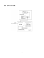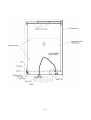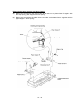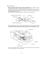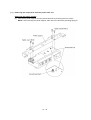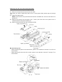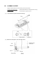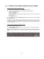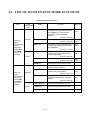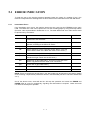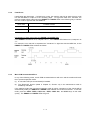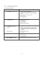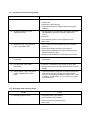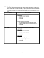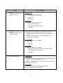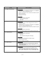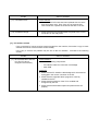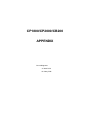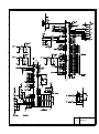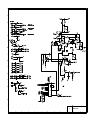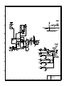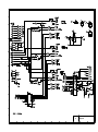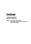
1
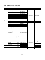
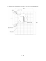
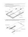
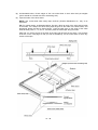
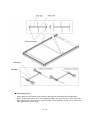
COPYBOARD
SERVICE MANUAL
MODEL: CP1800/CP2000/CB200
© Copyright Brother 2000
All rights reserved.
No part of this publication may be reproduced in any form or by any means without permission in writing
from the publisher.
Specifications are subject to change without notice.
All products and company names mentioned in this manual are trademarks or registered trademarks of their
respective holders.
PREFACE
This publication is a Service Manual covering the specifications, construction, theory of operation,
and maintenance of the Brother copyboard.
It includes information required for field
troubleshooting and repair--disassembly, reassembly, and lubrication--so that service personnel
will be able to understand machine function, to rapidly repair the machine and order any necessary
spare parts.
To perform appropriate maintenance so that the machine is always in best condition for the
customer, the service personnel must adequately understand and apply this manual.
This manual is made up of five chapters and appendix.
CHAPTER I.
GENERAL DESCRIPTION
CHAPTER II.
THEORY OF OPERATION
CHAPTER III.
DISASSEMBLY/REASSEMBLY AND LUBRICATION
CHAPTER IV.
MAINTENANCE MODE
CHAPTER V.
ERROR INDICATION AND TROUBLESHOOTING
Appendix.
Circuit Diagrams
This manual describes the models and their versions to be destined for major countries. The specifications
and functions are subject to change depending upon each destination.
CHAPTER I.
GENERAL DESCRIPTION
CHAPTER I. GENERAL DESCRIPTION
CONTENTS
1.1
1.2
MACHINE OUTLINE............................................................................................. I-1
1.1.1
External Appearance and Weight.............................................................. I-1
1.1.2
Components ............................................................................................. I-1
SPECIFICATIONS ................................................................................................ I-2
1.1 MACHINE OUTLINE
1.1.1 External Appearance and Weight
The figure below shows the machine appearance and approximate dimensions.
Weight:
CP2000/CB200
CP1800
Machine proper
14.5 kg (32.0 lbs.)
11.8 kg (26.0 lbs.)
In package
23.0 kg (50.7 lbs.)
19.5 kg (43.0 lbs.)
1.1.2 Components
The machine consists of the following major components:
I-1
1.2 SPECIFICATIONS
Model
CP2000
CB200
CP1800
Same as left.
Same as left.
MACHINE SPECIFICATIONS
INPUT
OUTPU
T
USE
POWER
Screen Size (H) x (W)
35.43 x 23.62 inches
900 x 600 mm
Effective Scanning Area (H) x (W)
34.57 x 23.39 inches
878 x 594 mm
Ratio of Scanning Area
96.60%
Scanning Method
CIS
Number of Screens
2 (Endless)
Number of Screens for Copy
2
Writing
Dry-erase markers
Printing Method
Thermal
Copy Size
Letter
Copy Speed
Monochrome: 18 sec
R&B: N/A
Continuous Copy
1 sheet
Paper
Therma PLUS, 30 m
Anti-Curl System (ACS)
Yes
Print Density
8 dots/mm
Easel Stand
Portrait
Wall Mount
Portrait/landscape
Partition Hanger
Portrait/landscape
Power Source
AC adapter supplied,
100 to 240 VAC,
50/60 Hz
Power Consumption
SIZE
Standby
Operating
Size (H x W x D) In package inch
Letter/A4
Same as left.
Letter
Same as left.
5W
30W
54.5 x 33.6 x 11.0
49.9 x 38.3 x 10.0
mm
1383 x 852 x 280
1267 x 973 x 255
inch
75.9 x 28.5 x 27.0
mm
1929 x 725 x 687
Use without easel stand
inch
49.9 x 28.5 x 5.8
(Portrait)
mm
1268 x 725 x 147
Use without easel stand
inch
33.3 x 45.2 x 5.8
(Landscape)
mm
846 x 1147 x 147
Weight
Net
14.5 kg (32.0 lbs)
11.8 kg (26.0 lbs)
Gross
23 kg (50.7 lbs)
19.5 kg (43.0 lbs)
Use with easel stand
PC I/F
Yes
N/A
N/A
Same as left.
Same as left.
Yes for Canada
I-2
Option
CHAPTER II.
THEORY OF OPERATION
CHAPTER II. THEORY OF OPERATION
CONTENTS
2.1
OVERVIEW........................................................................................................... II-1
2.2
MECHANISMS...................................................................................................... II-2
2.2.1 Scanner mechanism.................................................................................... II-2
2.2.2 Thermal printing mechanism ....................................................................... II-4
2.2.3 Sensors ....................................................................................................... II-5
2.3
CONTROL ELECTRONICS.................................................................................. II-6
2.1 OVERVIEW
II - 1
2.2 MECHANISMS
The machine consists of the following three mechanisms and sensors:
n Scanner Mechanism (Copyboard)
- Scrolling the copyboard screen
- Scanning the copyboard screen
n Thermal Printing Mechanism (Printer) - Printing image drawn on the copyboard screen and
feeding recording paper
n Easel Stand*
n Sensors
- PE/cover sensor
- Thermistor in the thermal recording head
- CIS unit which acts as a home position detector of the
copyboard screen
*Not provided for the CP1800.
2.2.1
Scanner mechanism
The scanner mechanism in the copyboard consists of a scanner, copyboard screen, WB motor,
and relay PCB, as illustrated on the next page.
The relay PCB, which is connected to the printer via the interface cable, relays power and control
signals sent from the main PCB of the printer to the WB motor and relays the scanned image with
control signals from the CIS units to the main PCB. If you press the FEED key, the WB motor
rotates to drive the screen feed pipe, scrolling up the copyboard screen.
The scanner uses three CIS units, each of which consists of an LED array illuminating the
copyboard screen via a glass prism bar, six lenses collecting the reflected light, and a CIS PCB
carrying out photoelectric conversion to output picture element data.
When pressing any copy-related key scrolls the copyboard screen, the CIS units scan the screen.
After a sequence of the scanning operation, the controller scrolls the screen further until the lefthand CIS unit detects either one of the two black home position (HP) marks pasted on the screen.
Home positioning of the copyboard screen is automatically performed also when you power on the
machine.
II - 2
II - 3
2.2.2
Thermal printing mechanism
The thermal printing mechanism in the printer consists of the thermal recording head, platen, anticurl system (ACS) plate, and paper compartment cover.
The heat-sensitive recording paper is routed between the paper guide bar and ACS plate to the
recording head which prints onto the paper pressed by the platen according to image signals
issued from the main PCB.
The ACS eliminates curl peculiar to rolled paper by curving the paper towards the opposite side of
the curl with the ACS plate.
If the printer motor (stepping motor) is driven, its rotational force is transmitted via the gear train in
the drive unit to the platen gear. The platen rotates to feed paper.
II - 4
2.2.3
Sensors
This machine has three sensors--PE/cover sensor (photosensor), thermistor in the thermal
recording head, and left-hand CIS unit acting as a home position detector of the copyboard screen.
The PE/cover sensor is located on the PE/cover sensor PCB secured to the recorder frame. It
detects whether the recording paper is present or the paper compartment cover is closed.
The thermistor in the recording head allows the controller to monitor the temperature of the head.
According to the change of the thermistor's internal resistance monitored, the controller manages
the duty cycle of the head drive current.
The left-hand CIS works as a home position detector of the copyboard screen also. If it detects
either of the two black HP marks pasted on the copyboard screen, it recognizes that the screen is
in the home position.
II - 5
2.3 CONTROL ELECTRONICS
II - 6
CHAPTER III.
DISASSEMBLY/REASSEMBLY AND
LUBRICATION
CHAPTER III. DISASSEMBLY/REASSEMBLY AND LUBRICATION
CONTENTS
3.1
DISASSEMBLY/REASSEMBLY ........................................................................... III-1
n
Safety Precautions.............................................................................................. III-1
n
Tightening Torque List ........................................................................................ III-2
n
Preparation......................................................................................................... III-3
n
How to Access the Object Component ................................................................ III-3
n
Disassembly Order Flow ..................................................................................... III-4
3.1.1
Disassembly of Printer................................................................................. III-5
[ 1 ] Separating the paper compartment cover from the printer base unit ...... III-5
[ 2 ] Removing the components from the paper compartment cover ............. III-8
Removing the paper guide bar and platen ............................................. III-8
Removing the lock shaft and paper compartment latch.......................... III-9
Removing the paper stoppers and platen frames................................... III-10
[ 3 ] Removing the components from the printer base unit ............................ III-12
Removing the printer support ................................................................ III-12
Removing the sub cover and control panel PCB.................................... III-13
Removing the main PCB and its bracket ............................................... III-14
Removing the drive unit and hinge plate L............................................. III-17
Removing the head protector, recording head ASSY, recorder frame,
and PE/cover sensor PCB ..................................................................... III-19
Removing the films ............................................................................... III-21
3.1.2
Disassembly of Copyboard ......................................................................... III-22
[ 1 ] Removing the CIS units......................................................................... III-22
Removing the upper cover, corner covers, CIS protector, and
upper support frame .............................................................................. III-22
Removing the CIS frame and CIS units ................................................. III-23
[ 2 ] Removing the relay PCB and printer-copyboard interface cable ............ III-26
Removing the lower cover, corner covers, CIS protector, and
lower support frame............................................................................... III-26
Removing the WB motor harness, relay PCB, and
printer-copyboard interface cable........................................................... III-27
i
[ 3 ] Removing the lower pipe and WB motor ............................................... III-29
Removing the lower corner plates and lower frame ............................... III-29
Removing the pipe holder stoppers, pipe spacer L, lower pipe and
its holders.............................................................................................. III-30
Removing the WB motor ....................................................................... III-33
[ 4 ] Replacing the white sheet (copyboard screen) and the sheet
backup board......................................................................................... III-35
3.2
LUBRICATION ..................................................................................................... III-40
[ 1 ] Joints between the platen shaft and its bushings.................................... III-40
[ 2 ] WB motor related gears on the lower pipe holder L ............................... III-40
[ 3 ] Lower pipe holder L ............................................................................... III-41
[ 4 ] Lower pipe holder R............................................................................... III-41
[ 5 ] Upper pipe shaft .................................................................................... III-42
ii
3.1 DISASSEMBLY/REASSEMBLY
n Safety Precautions
To prevent the creation of secondary problems by mishandling, observe the following precautions
during maintenance work.
(1) Turn the power off and unplug the AC cord from the power outlet before accessing parts or
units inside the machine. When disassembling the printer, unplug the AC adapter from the
left side of the printer.
(2) Be careful not to lose screws, washers, or other parts removed for parts replacement.
(3) When using soldering irons and other heat-generating tools, take care not to damage the resin
parts such as wires, PCBs, and covers.
(4) Before handling the PCBs, touch a metal portion of the machine to discharge static electricity;
otherwise, the electronic parts may be damaged due to the electricity charged in your body.
(5) When transporting PCBs, be sure to wrap them in conductive sheets such as aluminum foil.
(6) Be sure to reinsert self-tapping screws correctly, if removed.
When removing self-tapping screws from aluminum frames, aluminum material may stick to
the threads of those screws, requiring higher torque for retightening. If it happens, do not
tighten them forcedly, but use new screws and observe the specified torque values.
(7) Tighten screws to the torque values listed on the next page.
(8) When connecting or disconnecting cable connectors, hold the connector bodies not the
cables. If the connector has a lock, always slide the connector lock to unlock it.
(9) Before reassembly, apply the specified lubricant to the specified points. (Refer to Section
3.2.)
(10) After repairs, check not only the repaired portion but also that the connectors and other
related portions function properly before operation checks.
(11) After completion of repairs, always press the FEED key to scroll the copyboard screen (white
sheet) to the home position. This prevents the screen from leaving traces of being curled
along the upper and lower pipes within the scanning area.
Make sure that the copyboard screen is in the home position before storing or packing it.
III - 1
n Tightening Torque List
Location
Screw type
Q'ty
Tightening torque (N•m)
PRINTER
Platen stopper
Taptite, pan B M4x20
1
0.69 ±0.1
Platen frames R and L
Taptite, bind B M4x12
4
0.98 ±0.2
Printer support
Taptite, cup S M3x6
2
0.69 ±0.1
Taptite, bind B M4x12
2
0.98 ±0.2
Sub cover
Taptite, bind B M4x12
1
0.98 ±0.2
Panel cover
Taptite, bind B M4x12
2
0.98 ±0.2
Control panel PCB
Taptite, cup B M3x8
2
0.69 ±0.1
Main PCB
Taptite, cup S M3x6
2
0.69 ±0.1
Drive unit
Taptite, bind B M4x12
2
0.98 ±0.2
Printer motor cover
Taptite, cup S M3x6
1
0.69 ±0.1
Printer motor
Screw, pan (s/p washer) M3x6DB
1
0.69 ±0.1
Hinge plate L
Taptite, bind B M4x12
2
0.98 ±0.2
Recorder frame
Taptite, bind B M4x12
2
0.98 ±0.2
PE/cover sensor PCB
Taptite, cup S M3x6
1
0.69 ±0.1
Upper cover
Shoulder screw
3
0.78 ±0.1
Corner covers (upper)
Screw, flat S M3x10
4
0.78 ±0.1
CIS protector (upper)
Taptite, cup S M3x10
2
0.78 ±0.1
Upper support frame
Taptite, cup S M3x10
2
0.78 ±0.1
CIS frame
Taptite, cup S M3x10
4
0.78 ±0.1
CIS units
Taptite, bind B M3x8
6
0.39 ±0.1
Lower cover
Shoulder screw
3
0.78 ±0.1
Corner covers (lower)
Screw, flat S M3x10
4
0.78 ±0.1
CIS protector (lower)
Taptite, cup S M3x10
2
0.78 ±0.1
Lower support frame
Taptite, cup S M3x10
2
0.78 ±0.1
PCB support
Taptite, cup S M3x10
2
0.78 ±0.1
Relay PCB
Taptite, cup S M3x6
2
0.78 ±0.1
Printer-copyboard interface cable
Taptite, cup S M3x10
2
0.78 ±0.1
Lower corner plates R and L
Taptite, cup S M3x10
4
0.78 ±0.1
COPYBOARD
Taptite, washer S M3x10
1
0.78 ±0.1
Taptite, bind B 3x8
2
0.69 ±0.1
Pipe holder stoppers
Taptite, cup S M3x8
2
0.78 ±0.1
WB motor
Screw, pan (s/p washer) M3x6DB
2
0.78 ±0.1
Side covers R and L
Taptite, cup S M3x10
6
0.78 ±0.1
Lower frame
III - 2
n
Preparation
Prior to proceeding to the disassembly procedure,
(1) Unplug
- the AC cord and AC adapter and
- the optional PC interface cable if connected. (Not shown below.)
(2) Remove the tray and recording paper.
(3) CP2000/CB200: Take down the assembly of the copyboard and printer from the easel stand.
(4) Disconnect the printer-copyboard interface cable from the printer and then remove the four
decorative screws to separate the printer from the copyboard.
n
How to Access the Object Component
•
•
On the next page is a disassembly order flow which helps you access the object components.
To remove the main PCB, for example, first find it on the flow. You need to remove the printer,
printer base unit, printer support, and sub cover so as to access the main PCB.
Unless otherwise specified, the disassembled parts or components should be reassembled in
the reverse order of removal.
III - 3
n
Disassembly Order Flow
III - 4
3.1.1 Disassembly of Printer
[ 1 ] Separating the paper compartment cover from the printer base unit
(1) Open the paper compartment cover by pulling up its latch.
(2) Pull the paper guide bar in the direction of arrow • and unhook the hinge spring from the
shoulder screw (arrow ‚).
(3) Remove the retaining ring (E5) (arrow ƒ) from the shaft of the platen frame R.
(4) Shift the printer base unit in the direction of arrows „ and … to release it from the shafts of
the platen frame R and L, respectively.
III - 5
n Reassembling notes
When reinstalling the printer base unit to the paper compartment cover:
1) Hold the printer base unit at a right angle from the paper compartment cover and fit it
over the shafts of the platen frames L and R.
When doing this, take care not to bring the paper guide bar inside the tabs of the ACS
plate or not to bring the films inside the paper compartment cover.
III - 6
2) Set the retaining ring (E5) onto the shaft of the platen frame R.
3) Hook the hinge spring onto the shoulder screw.
III - 7
[ 2 ] Removing the components from the paper compartment cover
Removing the paper guide bar and platen
(1) If the printer base unit has not been removed, open the paper compartment cover by pulling
up its latch.
(2) Remove the retaining ring (E2) from each end of the paper guide bar, then remove the paper
guide bar from the paper stoppers R and L.
(3) Remove the platen stopper (one pan B taptite screw, M4x20).
(4) At the right end of the platen shaft, remove the platen gear by pulling its pawl outwards and
then remove the bushing R. At the left end, remove the pawled bushing L by pulling its pawls
outwards.
(5) Move the platen to the right (arrow •) to take out the left end from the platen frame L and
then take it out to the left (arrow ‚).
III - 8
Removing the lock shaft and paper compartment latch
(6) At the right end of the lock shaft, remove the lock lever by unlatching the pawls in the
direction of arrows • and pulling the lock lever outwards (arrow ‚) and then unhook the lock
lever spring from the platen frame R.
(7) Move the lock lever to the left (arrow ƒ). At the left end of the lock shaft, remove the lock
lever by unlatching the pawl (arrow „) and then unhook the lock lever spring from the platen
frame L. Take out the lock shaft (arrow …).
n Reassembling notes
•
When inserting the lock shaft through the paper compartment latch, face its short end to the
right as shown above.
III - 9
Removing the paper stoppers and platen frames
(8) Remove two screws from the platen frame R and take out the platen frame R together with
the hinge spring, paper stopper R and its spring.
(9) Remove two screws from the platen frame L and take out the platen frame L together with the
paper stopper L and its spring.
III - 10
n Reassembling notes
•
Before reinstalling the platen frames to the paper compartment cover, assemble the platen
frame R (or L), paper stopper, and stopper spring together as follows:
As illustrated below, first fit the stopper spring over the boss of the paper stopper. Insert the
bent end of the stopper spring into the cutout of the platen frame (arrow •), fit the boss of the
paper stopper into the hole of the platen frame (arrow ‚), and then fit the paper stopper to the
tab of the platen frame (arrow ƒ).
For the platen frame R, set the hinge spring on it as shown on the previous page.
•
When reinstalling the lock levers, first work at the platen frame L. As shown below with dotted
lines, hold the lock lever and then hook the lock lever spring onto the platen frame L. Next,
work the same way at the platen frame R and then snap the lock lever into the platen frame R.
•
When fitting the pawled bushing L and bushing R onto the platen shaft, align each guide boss
with the cutout provided in each of the bushings.
III - 11
[ 3 ] Removing the components from the printer base unit
Removing the printer support
(1) Take off the printer support from the printer base unit by removing the four screws.
NOTE: After removing the printer support, take care not to bend the grounding spring R.
III - 12
Removing the sub cover and control panel PCB
(2) Take off the sub cover by removing the screw.
(3) Disconnect the panel harness from the main PCB.
Only when you need to replace the panel cover or control panel PCB, perform steps (4) through
(6).
(4) Peel off the panel sheet.
NOTE: Once removed, the panel sheet will become unusable and a new one will have to be
put back in.
(5) Remove two screws from the panel cover. Push up the front face of the panel cover to
release its latches and pull it towards you.
(6) Remove the two screws from the control panel PCB.
n Reassembling notes
•
When securing the panel cover with screws, press it in the direction of arrows "A" and "B" as
shown below.
•
When securing the sub cover with a screw, press it in the direction of arrows • through ƒ as
shown below.
III - 13
Removing the main PCB and its bracket
(7) Disconnect the following harnesses from the main PCB while holding down the main PCB:
- Recording head signal harness
- Sensor harness
- Panel harness (if connected)
- Printer motor harness
- Recording head power harness
III - 14
(8) Remove the PC interface cover if mounted.
(9) Remove two screws and take out the main PCB.
III - 15
(10) Remove the grounding screw from the underside of the printer base unit.
(11) Remove two screws from the PCB bracket and take it out.
NOTE: When removing the PCB bracket, take care not to drop the grounding spring L.
n Reassembling notes
•
•
•
•
When setting the grounding spring L back into place, position the end of the spring within the
semicircle as shown above.
When securing the main PCB with screws, align its left and front edges with the PCB bracket
and the positioning ribs as illustrated on the previous page.
If the main PCB is replaced with a new one (not with a used board), powering on the machine
at the first time from the replacement will make the ERROR and PAPER LEDs flash at 0.5second intervals, indicating that the machine has automatically entered the in-process
inspection mode.
To exit from this mode, press the COPY, FEED, COPY ALL, FEED, COPY ALL, and COPY
keys in this order quickly. The ERROR and PAPER LEDs will go off. If these LEDs remain
flashing, turn the machine power off and then on and perform the same exit procedure.
After replacement of the main PCB, it is necessary to set scanning compensation parameters
stored in the EEPROM and customize the EEPROM for the page length.
- Setting scanning compensation parameters
If both the printer and copyboard are brought to the service station, set the scanning
compensation parameters (Function code 55) as described in Subsection 4.3.1.
If only the printer is brought to the service station, make automatic setting of the scanning
compensation parameters (Function code 02) as described in Subsection 4.3.3.
- Customizing the EEPROM
Customize the EEPROM for page length according to machine models (Function code 32) as
described in Subsection 4.3.7.
III - 16
Removing the drive unit and hinge plate L
(12) Remove two screws from the drive unit.
(13) Slightly lift up the drive unit and disconnect the printer motor harness from the motor.
NOTE: After removing the drive unit, take care not to drop the grounding spring L.
(14) Take off the motor cover by removing the screw.
(15) Take off the printer motor by removing the screw.
(16) Remove two screw from the hinge plate L and take it off.
III - 17
n Reassembling notes
•
•
•
When connecting the printer motor harness, connect its end which is far from the ferrite core to
the motor and its end near the core to the main PCB as illustrated on the previous page.
When setting the drive unit back into place, route the printer motor harness as shown below.
Route the printer motor harness through two cable guides and position the ferrite core between
the cable guide and cutout as illustrated below.
III - 18
Removing the head protector, recording head ASSY, recorder frame, and PE/cover sensor
PCB
(17) While pulling up the left end of the head protector, unhook latches • through „ in this order
with a small flat screwdriver as illustrated below.
(18) Push down both ends of the recording head ASSY and move it to the rear to release the tabs
from the cutouts provided in the recorder frame.
(19) Disconnect the two harnesses (recording head signal and power harnesses) from the
recording head ASSY and then lift it up.
(20) Remove three head springs.
III - 19
(21) Remove two screws from the recorder frame.
(22) Slightly lift up the recorder frame and disconnect the sensor harness from the PE/cover
sensor PCB.
(23) Take off the PE/cover sensor PCB by removing the screw.
(24) Remove the sensor actuator as shown below.
n Reassembling notes
•
Before setting the recorder frame back into place, make sure that the ACS spring is fitted in the
U-shaped cutout of the recorder frame as illustrated above.
III - 20
•
After reassembly, make sure that the harnesses are routed as shown below.
Removing the films
NOTE: Once removed, the films will become unusable and new ones will have to be put back in.
(25) Remove the films as shown below.
n Reassembling notes
•
Attach the adhesive face of each film to the hatched section of the printer base unit within the
rib as shown above.
III - 21
3.1.2 Disassembly of Copyboard
[ 1 ] Removing the CIS units
Removing the upper cover, corner covers, CIS protector, and upper support frame
(1) Remove the upper cover (three shoulder screws).
(2) Remove the corner covers A and B (two flat S screws, M3x10 from each cover).
(3) Remove the CIS protector (two cup S taptite screws, M3x10).
(4) Remove the upper support frame (two cup S taptite screws, M3x10).
III - 22
Removing the CIS frame and CIS units
(5) Remove the CIS frame (two cup S taptite screws, M3x10 from its each end).
(6) Pivot up the CIS frame as shown below, remove the three harness sponges, disconnect the
three CIS harnesses from the CIS units, and then lift up the CIS frame.
NOTE: When handling the CIS frame, hold it as shown below, taking care not to touch the
glass prism bars or transparent sheets. If you touch any of them, be sure to wipe it with a soft
cloth. NEVER use alcohol to clean it.
III - 23
(7) Remove three CIS units (two bind B taptite screws, M3x8 from each CIS unit) from the CIS
frame.
n Reassembling notes
•
•
•
If any one of the three CIS units is defective, replace the three-unit set with a new set.
When securing the CIS units to the CIS frame with screws, press each of those units and CIS
frame to each other with your fingers as shown above.
When reinstalling the CIS frame, first connect the three CIS harnesses to the CIS units
according to the ID color, set the CIS frame back into place, and then put three sponges into
the positions specified on the previous page to secure those harnesses.
Next, set the two positioning jigs in the direction of arrows • and ‚, with its shorter end facing
towards the CIS units. While pressing the positioning jigs in the direction of arrow ƒ, tighten
four screws in the order of (a), (b), (c), and (d) shown below. When removing the positioning
jigs, check again that there is no looseness.
III - 24
•
•
•
•
If you replace the CIS unit set, set the scanning compensation parameters stored in the
EEPROM (Function code 55) as described in Subsection 4.3.1.
When securing the upper support frame to the side frames, sandwich the spacers between
them as shown on page III-22.
Once the CIS protector is removed, the CIS clamp on the protector should be replaced with a
new one.
Before setting the removed CIS protector back into place, remove the current CIS clamp. After
securing the CIS protector, attach a new CIS clamp instead, taking care not to let the new CIS
clamp protrude from the rear edge of the CIS protector.
When securing the upper cover, temporarily tighten the three shoulder screws (shown on page
III-22), center the upper cover relative to the corner covers, and then firmly tighten those
screws.
III - 25
[ 2 ] Removing the relay PCB and printer-copyboard interface cable
Removing the lower cover, corner covers, CIS protector, and lower support frame
(1) Remove the lower cover (three shoulder screws).
(2) Remove the corner covers A and B (two flat S screws, M3x10 from each cover).
(3) Remove the CIS protector (two cup S taptite screws, M3x10).
(4) Remove the lower support frame (two cup S taptite screws, M3x10).
III - 26
Removing the WB motor harness, relay PCB, and printer-copyboard interface cable
(5) Disconnect the WB motor harness from the relay PCB and the WB motor. On the relay PCB,
straighten the cable clip and pull out the ferrite core of the harness. Then take the WB motor
harness out of the cable clamps.
(6) Remove the tape from the CIS harness set and straighten the two cable clips.
(7) Disconnect the red CIS harness from the relay PCB and pull it out from the cable clip. In the
same way, release the yellow and blue CIS harnesses.
III - 27
(8) Turn the copyboard upside down.
(9) On the grip, straighten the cable clip and release the printer-copyboard interface cable.
(10) Remove the PCB support (two cup S taptite screws, M3x10) together with the printercopyboard interface cable and the relay PCB.
(11) Remove two screws (two cup S taptite screws, M3x6) from the relay PCB and disconnect the
printer-copyboard interface cable.
(12) Remove the printer-copyboard interface cable (two cup S taptite screws, M3x10 on the cable
clamp).
III - 28
n Reassembling notes
•
•
•
•
Before connecting each of the CIS harnesses to the relay PCB, be sure to fit its ferrite core
over the cable clip. As shown on page III-27, in the order of the blue, yellow, and red CIS
harnesses, fit their ferrite cores over the cable clip and then connect those harnesses to the
relay PCB.
After routing the CIS harnesses and WB motor harness, make sure that those harnesses and
their ferrite cores do not interfere with the white sheet and frames, respectively.
When securing the lower support frame to the side frames, sandwich the spacers between
them as shown on page III-26.
When securing the lower cover, temporarily tighten the three shoulder screws (shown on page
III-26) in the center screw hole and outer screw holes, center the lower cover relative to the
corner covers, and then firmly tighten those screws.
[ 3 ] Removing the lower pipe and WB motor
Removing the lower corner plates and lower frame
(1) Remove the lower corner plates R and L (two cup S taptite screws, M3x10 from each plate).
III - 29
(2) Remove the lower frame (one washer S taptite screw, M3x10 and two bind B taptite screws,
M3x8) and then pull it out.
NOTE: When placing the copyboard rightside up after removing the lower frame, apply any
pad under the copyboard to protect the grip as shown below.
Removing the pipe holder stoppers, pipe spacer L, lower pipe and its holders
(3) Remove two pipe holder stoppers (one cup S taptite screw, M3x8 from each stopper).
III - 30
(4) Unhook the pipe holder springs from the lower pipe holders R and L.
(5) While scrolling the white sheet (copyboard screen), slide it in the direction of arrow • so that
the pipe spacer L can appear.
(6) Remove the pipe spacer L in the direction of arrow ‚.
III - 31
(7) Press the pipe gear in the direction of arrow • and disengage it from the lower pipe holder L,
then pull out the lower pipe in the direction of arrow ‚.
(8) Take out the lower pipe holders R and L in the direction of the arrows.
III - 32
Removing the WB motor
(9) Remove the WB motor (two pan screws with S/P washer, M3x6DB) from the lower pipe holder
L.
n Reassembling notes
•
•
When securing the WB motor to the lower pipe holder L, first tighten a screw in the smaller
screw hole.
Before securing the lower corner plates R and L with screws, at the top of the frame ASSY
check that the difference between distances "A" and "B" (shown on the next page) is within 1
mm, where "A" and "B" are distances from the top edge of the backboard to the rib of the upper
frame.
If the difference exceeds 1 mm, loosen (not remove) all screws E, press the frame ASSY in the
direction of C or D to fix the ASSY's distortion, tighten screws E, and then secure the lower
corner plates R and L with screws.
If the frame ASSY is distorted, the right or left edge of the white sheet will become slack,
causing the white sheet to come into contact with the upper cover.
III - 33
III - 34
[ 4 ] Replacing the white sheet (copyboard screen) and the sheet backup board
(1) Remove the six screws (three cup S taptite screws, M3x10 from each side cover) from the
side covers and slide them as shown below.
NOTE: When sliding the side covers, take care not to damage the CIS harnesses.
(2) Cut the white sheet to be replaced with scissors.
NOTE: Do not use a cutter or knife which could damage the sheet backup board.
III - 35
(3) Paste two black HP marks onto the ruled side of a new white sheet as specified below.
III - 36
(4) As illustrated below, put the new white sheet on the old one with the ruled side facing up and
black HP marks facing towards the left.
(5) Tape the edge of the new white sheet to the cut edge of the old one.
(6) Pull the other edge of the old white sheet in the direction of the black arrow. This will set the
new white sheet around the sheet backup board.
(7) To replace the sheet backup board, remove two screws (one cup S taptite screw, M3x10 from
each side frame) and pull out the board together with its supports. Set a new board back into
place together with the removed supports and tighten two screws.
III - 37
(8) As illustrated below, fit both edges of the new white sheet to each other and put weights
(which should be covered with felt or something soft).
(9) Tape the seam of the white sheet.
NOTE: Use 10-mm-wide white sticky tape, 631S-50 (Teraoka Seisakusho Co., Ltd.) or its
equivalent.
TIP: For easier taping, as illustrated below, first put a block at each of the right and left ends
of the seam, cut a strip of the white sticky tape longer than the width of the white sheet, and
temporarily attach the tape to those blocks. Push the tape down to the seam of the white
sheet at three points •, ‚, and ƒ, and then press the entire tape along the seam.
After that, cut off the excess of the tape at the right and left ends of the seam. Use scissors
as shown on the next page so that you will not mistakenly cut the white sheet or leave any
excess of the tape.
III - 38
n Reassembling notes
•
•
When sliding the side covers back into place, take care not to damage the CIS harnesses.
When securing the side covers, first temporarily tighten the three screws at each side cover.
After securing the corner covers, center the side covers relative to those corner covers and
then tighten those screws firmly.
III - 39
3.2 LUBRICATION
Apply the specified lubricant to the lubrication points as shown below.
Lubricant type (Manufacturer):
Molykote grease EM-30L or EM-30LG (Dow Corning)
Lubricant amount:
Rice-sized pinch of grease (6 mm3)
[ 1 ] Joints between the platen shaft and its bushings
[ 2 ] WB motor related gears on the lower pipe holder L
III - 40
[ 3 ] Lower pipe holder L
[ 4 ] Lower pipe holder R
III - 41
[ 5 ] Upper pipe shaft
III - 42
CHAPTER IV.
MAINTENANCE MODE
CHAPTER IV. MAINTENANCE MODE
CONTENTS
4.1
ENTRY INTO THE MAINTENANCE MODE.......................................................... IV-1
4.2
LIST OF MAINTENANCE-MODE FUNCTIONS .................................................... IV-2
4.3
DETAILED DESCRIPTION OF MAINTENANCE-MODE FUNCTIONS ................. IV-3
4.3.1
Setting of the scanning compensation parameters stored in the EEPROM
(involving home positioning of the copyboard screen) [Function code 55]...... IV-3
4.3.2
Scanning contrast adjustment [Function code 07].......................................... IV-4
4.3.3
Automatic setting of the scanning compensation parameters stored
in the EEPROM [Function code 02] ............................................................... IV-5
4.3.4
Dump (including page length setting, error code, and scanning
compensation data) [Function code 05] ......................................................... IV-6
4.3.5
Test pattern print [Function code 09] ............................................................. IV-8
4.3.6
Operational check of keys and LEDs on the control panel
[Function code 13].......................................................................................... IV-9
4.3.7
Sensor operational check and EEPROM customization (for page length)
[Function code 32].......................................................................................... IV-9
4.1 ENTRY INTO THE MAINTENANCE MODE
To make the machine enter the maintenance mode:
(1) Open the paper compartment cover. The PAPER LED comes on.
(2) Hold down the following two keys at the same time for at least 15 seconds:
- COPY ALL and FEED keys or
- COPY and FEED keys
Which key combination should be selected depends upon the maintenance-mode functions
you want to access.
The ERROR LED flashes.
When the PAPER LED is on and the ERROR LED is flashing, the machine is in the initial stage of
the maintenance mode.
To select one of the maintenance-mode functions listed in Section 4.2, keep the paper
compartment cover opened or close it (depending upon the maintenance-mode functions you want
to access) and then press the specified key. The details of each maintenance-mode function are
described in Section 4.3.
To make the machine exit from the maintenance mode:
(1) Close the paper compartment cover.
(2) Press the FEED key in the initial stage of the maintenance mode. The machine will return to
the regular operation mode.
NOTE: If no keys are pressed for 10 seconds in the initial stage of the maintenance mode, the
machine will automatically exit from the maintenance mode and return to the regular operation
mode.
IV - 1
4.2 LIST OF MAINTENANCE-MODE FUNCTIONS
Maintenance-mode Functions
Entry
Open the
paper
compartment
cover.
Hold down
COPY ALL
and FEED
keys for 15
seconds.
Paper
compartment
cover
Opened
Function
COPY ALL key
Setting of the scanning
compensation parameters stored in
the EEPROM (involving home
positioning of the copyboard
screen)
[Function code 55]
Sect.
4.3.1
COPY key
Scanning contrast adjustment
[Function code 07]
Sect.
4.3.2
FEED key
Automatic setting of the scanning
compensation parameters stored in
the EEPROM
[Function code 02]
Sect.
4.3.3
COPY ALL key
Dump (including page length
setting, error code, and scanning
compensation data)
[Function code 05]
Sect.
4.3.4
COPY key
Test pattern print
Sect.
4.3.5
Closed
[Function code 09]
Open the
paper
compartment
cover, then
press COPY
and FEED
keys for 15
seconds.
FEED key
Exit from the maintenance mode
COPY ALL key
Reserved.
(Never use this function.)
COPY key
Operational check of keys and
LEDs on the control panel
[Function code 13]
Sect.
4.3.6
FEED key
Sensor operational check and
EEPROM customization (for page
length)
[Function code 32]
Sect.
4.3.7
COPY ALL key
Exit from the maintenance mode
COPY key
Exit from the maintenance mode
FEED key
Exit from the maintenance mode
Opened
Closed
Refer to:
Press:
IV - 2
4.3 DETAILED DESCRIPTION OF
MAINTENANCE-MODE FUNCTIONS
4.3.1
n
Setting of the scanning compensation parameters stored in the EEPROM (involving home
positioning of the copyboard screen) [Function code 55]
Function
The machine performs home-positioning of the copyboard screen (using black HP marks on the
screen) and sets the scanning compensation parameters registered in the EEPROM.
n
Operating Procedure
(1) Open the paper compartment cover and hold down the COPY ALL and FEED keys for 15
seconds.
(2) Press the COPY ALL key with the paper compartment cover opened.
The machine checks whether either of the two black HP marks on the copyboard screen is
placed in the home position (i.e. in the scanning position). If neither mark is in the home
position, the machine scrolls up the copyboard screen until either mark comes to the home
position.
After detection of either black HP mark, the machine flashes the PAPER LED and starts
setting the scanning compensation parameters in the EEPROM.
Upon completion of parameter setting, the machine turns the PAPER LED off and returns to
the regular operation mode.
If any error occurs during this procedure, the machine prints out an error code and returns to
the regular operation mode.
IV - 3
4.3.2
n
Scanning contrast adjustment [Function code 07]
Function
This function allows you to adjust the scanning contrast to five levels from 0 to 4 for monochrome
scanning. The contrast level refers to the threshold value of brightness to be applied for 2-value
quantization when the CIS scans images drawn on the copyboard screen.
The default scanning level is 2.
n
Operating Procedure
(1) Open the paper compartment cover and hold down the COPY ALL and FEED keys for 15
seconds.
(2) Press the COPY key with the paper compartment cover opened.
The ERROR LED stops flashing for one second and then starts flashing again.
(3) Press the COPY key to show the current scanning contrast.
Then, the machine shows the current contrast by using the ERROR and PAPER LEDs as
shown below.
Contrast Indication by ERROR and PAPER LEDs
If the LEDs flash in the cycle below:
ERROR ON once and PAPER ON four times*
The current contrast level is:
0
ERROR ON two times and PAPER ON three times
1
ERROR ON three times and PAPER ON two times
2
ERROR ON four times and PAPER ON once
3
ERROR ON five times
4
(Light)
(Dark)
(*Example: Contrast level 0)
(4) To decrease the contrast, press the COPY ALL key; to increase it, press the FEED key.
(5) Press the COPY key.
The new setting will be fixed and the machine returns to the regular operation mode.
IV - 4
4.3.3
n
Automatic setting of the scanning compensation parameters stored in the EEPROM
[Function code 02]
Function
This function allows you to make automatic setting of the scanning compensation parameters so
that the machine will automatically start home-positioning of the copyboard screen and set the
scanning compensation parameters stored in the EEPROM as described in Section 4.3.1 at the
next powering-on time.
You need to use this function when you replace the main PCB but cannot set the scanning
compensation parameters in the EEPROM since only the printer is received for repair.
When the repaired printer is returned to the user and he/she turns on the power, the machine will
automatically start home-positioning and set the scanning compensation parameters without
bothering him/her.
n
Operating Procedure
At the service site:
(1) Open the paper compartment cover and hold down the COPY ALL and FEED keys for 15
seconds.
(2) Press the FEED key with the paper compartment cover opened.
The machine writes the automatic scanning parameter setting code into the EEPROM and
returns to the regular operation mode.
At the user site:
(1) Power on the machine.
The machine automatically starts home positioning of the copyboard screen and sets the
scanning compensation parameters in the EEPOM. (Refer to Section 4.3.1, Operating
Procedure, (2).) After that, the machine will clear the automatic scanning parameter setting
code.
If any error occurs during this procedure, the machine scrolls the copyboard screen again until
it detects another black HP mark and tries to set the scanning compensation parameters
again. If the error still persists, the machine scrolls the copyboard screen again until it detects
another black HP mark, prints an error code, and then returns to the regular operation mode.
The automatic scanning parameter setting code will not be cleared.
IV - 5
4.3.4
n
Dump (including page length setting, error code, and scanning compensation data)
[Function code 05]
Function
This function prints out the following data:
- Page length setting for recording paper
- Error code
- Scanning compensation data
n
Operating Procedure
(1) Open the paper compartment cover and hold down the COPY ALL and FEED keys for 15
seconds.
(2) Close the paper compartment cover and press the COPY ALL key.
The machine prints out the following:
- Page length setting for recording paper
PAPER SIZE LETTER (if the letter size is selected)
PAPER SIZE A4
(if the A4 size is selected)
- Error code
ERR=xx (where xx denotes the latest error code. For details, refer to Chapter V.)
- Scanning compensation data
a) White level data for green LEDs in CIS0 (66 bytes)
b) White level data for green LEDs in CIS1 (72 bytes
c) White level data for green LEDs in CIS2 (63 bytes)
d) White level data for red LEDs in CIS0 (66 bytes)
e) White level data for red LEDs in CIS1 (72 bytes)
f) White level data for red LEDs in CIS2 (63 bytes)
g) Clamp PWM value (2 bytes)
h) Gain PWM value (12 bytes for green and red images, 6 bytes/color)
i) Compensation coefficient data for background color (12 bytes for green and red
LEDs, 2 bytes/color/CIS)
Upon completion of printout, the machine returns to the regular operation mode.
NOTE: If any data is abnormal, its code will be printed in inline style, as shown on the next
page.
NOTE: All bytes of codes in d), e) and f), the last six bytes of codes in h), and the last three
bytes of codes in i) might be printed in inline style as abnormal; however, they can be ignored
for machines not supporting red & black copying. Those compensation data are needed for
red & black copying.
IV - 6
a)
b)
c)
d)
e)
f)
g)
h)
i)
Dump List
IV - 7
4.3.5
n
Test pattern print [Function code 09]
Function
This function, much like the copying function, prints out a test pattern to allow you to check for
record data missing or print quality.
n
Operating Procedure
(1) Open the paper compartment cover and hold down the COPY ALL and FEED keys for 15
seconds.
(2) Close the paper compartment cover and press the COPY key.
The machine prints out the specified test pattern as shown below.
printing, the machine returns to the regular operation mode.
Upon completion of
*
Test Pattern
* Check these two rows of patterns for print quality. Ignore other rows of patterns. The print
should be free from faint section, white streaks, and black streaks and printed uniformly in black.
IV - 8
4.3.6
n
Operational check of keys and LEDs on the control panel [Function code 13]
Function
This function allows you to check the keys and LEDs on the control panel.
n
Operating Procedure
(1) Open the paper compartment cover and hold down the COPY and FEED keys for 15
seconds.
(2) Press the COPY key with the paper compartment cover opened.
The ERROR and PAPER LEDs start flashing at 0.5-second intervals alternately.
(3) Press the COPY ALL key.
The PAPER LED goes off but the ERROR LED keeps flashing.
(4) Press the COPY key.
The ERROR LED goes off and the PAPER LED starts flashing.
(5) Press the FEED key.
The PAPER LED goes off.
The machine returns to the regular operation mode.
4.3.7
n
Sensor operational check and EEPROM customization (for page length) [Function code 32]
Function
This function allows you to check whether the PE/cover sensor works correctly. After checking the
sensor, you select letter or A4 size for page length.
n
Operating Procedure
(1) Open the paper compartment cover and hold down the COPY and FEED keys for 15
seconds.
(2) Press the FEED key with the paper compartment cover opened.
The PAPER LED should come on.
(3) Load paper, then close or open the paper compartment cover to check that the PAPER LED
goes off or comes on, respectively.
Remove or set the recording paper to check that the PAPER LED comes on or goes off,
respectively.
(4) Press the COPY key.
The ERROR LED should come on if it was off.
The ERROR LED should go off if it was on.
Before proceeding to the following steps, fix the sensor problem (if any) and check that the
ERROR LED goes off.
IV - 9
(5) Make sure paper is loaded and close the paper compartment cover. Check that both the
ERROR and PAPER LEDs go off.
(6) To set A4 size, press the COPY ALL key.
To set letter size, press the FEED key.
Both the ERROR and PAPER LEDs come on.
(7) Press the COPY key to deactivate the R & B copying function*.
(*The programs support the R & B copying function, but the current CIS units do not.
Therefore, if you press the COPY ALL key instead of the COPY key so as to activate the R &
B copying function, an error will occur in the scanning test, disabling the machine.)
Both the ERROR and PAPER LEDs go off and the machine returns to the regular operation
mode.
(8) To check that the correct page length is set, print out a dump list (refer to Subsection 4.3.4).
(9) To make sure that the R & B copying function is deactivated, press the COPY ALL key after
performing the above procedure. If images on two sides of the copyboard screen are printed
out, the R & B copying function has been deactivated; if images on a single side only is
printed out or a scanning error occurs, then the R & B copying function has been enabled, so
you need to perform the above procedure again.
IV - 10
CHAPTER V.
ERROR INDICATION AND
TROUBLESHOOTING
CONTENTS
5.1 ERROR INDICATION ........................................................................................... V-1
5.1.1
Intermittent Errors ..................................................................................... V-1
5.1.2
Fatal Errors............................................................................................... V-2
5.1.3
Main PCB Uncustomized Error ................................................................. V-2
5.2 TROUBLESHOOTING.......................................................................................... V-3
5.2.1
Introduction............................................................................................... V-3
5.2.2
Locating a printer or copyboard failure ---Important--- .............................. V-3
Read This First User Setup Guide for Repaired Machine ........................ V-4
5.2.3
Precautions............................................................................................... V-5
5.2.4
Checking prior to Troubleshooting............................................................. V-5
5.2.5
Troubleshooting Procedures ..................................................................... V-6
[1]
Control panel related..................................................................... V-6
[2]
Copyboard screen scrolling related................................................ V-7
[3]
Recording paper feeding related ................................................... V-7
[4]
Copy-image related....................................................................... V-8
[5]
PC interface related ...................................................................... V-11
5.1 ERROR INDICATION
To help the user or the service personnel promptly locate the cause of a problem (if any), the
machine incorporates the self-diagnostic functions which show intermittent errors and fatal errors.
5.1.1
Intermittent Errors
If an intermittent error occurs, the machine stores the error code into the EEPROM on the main
PCB. The latest error code can be printed out onto the recording paper by using the dump feature
(Function code 05) described in Subsection 4.3.4. The table below lists error codes which would
be printed out by the feature.
Error code
Probable causes
LED
8B
Recording head overheated, according to the internal
resistance of the thermistor.
ERROR ON
A1
No recording paper loaded or the paper compartment cover
opened, according to the PE/cover sensor.
PAPER ON
(A4
Faulty of white level data.)
AB
Home positioning of the copyboard screen failed. (The CIS
cannot detect either of the black HP marks on the screen.)
(B1
Upper limit of clamp PWM value.)
(B2
Lower limit of clamp PWM value. This error occurs also if
interference light comes into the CIS units.)
(B3
Upper limit of gain PWM value. This error occurs also if the
printer-copyboard interface cable is not connected.)
(B4
Lower limit of gain PWM value.)
E6
Write error in EEPROM.
F6
PC interface error.
NOTE: Errors enclosed with parentheses in the above table can be printed out only during setting
of the scanning compensation parameters stored in the EEPROM (Function code 55 in Subsection
4.3.1).
Out of the above errors, errors 8B and A1 will stop the operation and cause the ERROR and
PAPER LEDs to come on, respectively, signaling user intervention is required. Other errors will
not affect the subsequent operation.
V-1
5.1.2
Fatal Errors
Listed below are fatal errors. If a fatal error occurs, the machine may fail to store the error code
into the EEPROM or output it to the recording paper. To signal the fatal error, therefore, the
machine employs flash codes using the ERROR and PAPER LEDs in the following way to indicate
the error code in eight bits with the MSB first.
Error code
Probable causes
55
Write error into the work area of the RAM.
A5
Access to the EEPROM impossible.
Interpretation of flash codes using the ERROR and PAPER LEDs
If the ERROR LED flashes once, interpret it as "1"; if the PAPER LED flashes once, interpret it as
"0."
For example, error code A5 is expressed as "10100101" in eight bits with the MSB first, so the
ERROR and PAPER LEDs will flash as follows:
5.1.3
Main PCB Uncustomized Error
In any of the following cases, a main PCB uncustomized error will occur and the machine will enter
the in-process inspection mode.
(1) A new main PCB (not a used board) is installed.
(2) The "Reserved" function (listed in Chapter IV, Section 4.2) in the maintenance mode is
mistakenly activated.
If the machine enters the in-process inspection mode (in which a sequence of the checks will be
automatically made), the ERROR and PAPER LEDs will flash at 0.5-second intervals. To exit this
mode, press the COPY, FEED, COPY ALL, FEED, COPY ALL, and COPY keys in this order
quickly. The ERROR and PAPER LEDs will go off.
V-2
5.2 TROUBLESHOOTING
5.2.1
Introduction
This section gives the service personnel some of the troubleshooting procedures to be followed if
an error or malfunction occurs with the machine. It is impossible to anticipate all of the possible
problems which may occur in future and determine the troubleshooting procedures, so this section
covers some sample problems. However, those samples will help service personnel pinpoint and
repair other defective elements if he/she analyzes and examines them well.
5.2.2
Locating a printer or copyboard failure --- Important --This machine is so designed that the printer can be easily separated from the copyboard. If it is
apparent that the printer is faulty, therefore, the user may remove it from the copyboard and send
it to the service station.
Test pattern print (Function code 09)
To check whether the printer is faulty, use the test pattern print function (Function code 09 in
Subsection 4.3.5). The service personnel may print a test pattern by himself/herself or instruct the
user by phone to do it.
If the printed test pattern is abnormal, the printer is faulty; if normal, the scanner in the copyboard
may be faulty so that both the printer and copyboard should be brought to the service station.
Automatic setting of the scanning compensation parameters (Function code 02)
If you replace the main PCB, you need to set the scanning compensation parameters in the
EEPROM (Function code 55 in Subsection 4.3.1). However, if only the printer has been brought to
the service station, you cannot do it. In such a case, make automatic setting of the scanning
compensation parameters (Function code 02 in Subsection 4.3.3).
User setup guide for repaired machine
If you make automatic setting of the scanning compensation parameters, the machine will
automatically start home-positioning of the copyboard screen and set the scanning compensation
parameters stored in the EEPROM when the user powers on the repaired machine first after
reception.
You need to tell the user what will automatically happen when he/she powers on the machine, for
preventing the user from worrying unnecessarily. The automatic operation may take approx. three
minutes during which the PAPER LED flashes.
If the machine fails to set the scanning compensation parameters, it will print out an error sheet. If
it happens repeatedly, instruct the user to clean the copyboard screen in the vicinity of the home
positions and the scanner (CIS units) according to the User's Manual, "Maintenance."
On the next page is a sample of a user setup guide. It is recommended that you prepare such a
note translated into the corresponding language and attach it to the repaired printer at the time of
returning.
V-3
Sample
Read This First
User Setup Guide for Repaired Machine
Thank you very much for your patronage. We have repaired your printer and are sending it back
to you.
To ensure you get the most out of the performance in the machine, follow all instructions given
below.
(1)
Clean the whole surface of the looped copyboard screen while scrolling it slowly by hand. If
stains cannot be wiped off easily, use a soft cloth dampened with water.
(2)
Connect the printer to the copyboard and set up the machine according to the setting-up
instructions given in the User's Manual. Make sure that the printer-copyboard interface cable
and the AC adapter cable are plugged in firmly.
(3)
Load the recording paper to the printer. Check that it is not slack.
(4)
Turn the power on.
The machine automatically scrolls the copyboard screen for home positioning and starts
setting the scanning compensation parameters stored in the EEPROM. This automatic
operation may take approx. three minutes during which the PAPER LED flashes.
(5)
Upon completion of the automatic setting, the machine turns off the PAPER LED and returns
to the regular operation mode.
(6)
If the machine fails to set those parameters, it will print out an error sheet.
If ERR=A4, go to step (7).
If ERR=AB, skip to step (8).
If ERR=B3, go back to step (2).
(7)
Turn the power off and check the copyboard screen for stains. Then repeat steps (2) through
(4).
If the error still persists, power off the machine and clean the scanner (CIS units) according to
the User's Manual, "Maintenance, Cleaning the scanner." And then repeat steps (1) through
(4) again.
If the error still persists, the scanner components may be defective. With the error sheet
close at hand, call the telephone number given below.
(8)
Turn the power off. Turn the power on and check that the copyboard screen scrolls normally.
If any abnormal noise is heard or the scrolling speed is abnormally low, the screen drive
components may be defective. With the error sheet close at hand, call the telephone number
given below.
If the copyboard screen scrolls normally, go back to step (7).
TEL NO.: XXX-XXX-XXXX (telephone number of the service station)
V-4
5.2.3
Precautions
Be sure to observe the following to prevent the secondary troubles from happening:
(1)
Always unplug the AC cord from the outlet when removing the covers and PCBs, adjusting
the mechanisms, or conducting continuity testing with a circuit tester.
(2)
When disconnecting the connectors, do not pull the lead wires but hold the connector
housings.
(3)
l
Before handling the PCBs, touch a metal portion of the machine to discharge static
electricity charged in your body.
l
When repairing the PCBs, handle them with extra care.
After repairing the defective section, be sure to check again if the repaired section works correctly.
Also record the troubleshooting procedure so that it would be of use for future trouble occurrence.
5.2.4
Checking prior to Troubleshooting
Prior to proceeding to the troubleshooting procedures given in Subsection 5.2.5, make the
following initial checks:
Environmental conditions
Check that:
(1) The machine is placed on a flat, firm surface.
(2) The machine is used in a clean environment at or near normal room temperature (10°C to
35°C) with normal relative humidity (45 to 80%).
(3) The machine is not subjected to rapid change of the ambient temperature. (Moving the
machine from a cold place to warm place will cause condensation inside the machine. If it
takes place, leave the machine in the warm place for approx. two hours before turning on the
power.) Powering on the machine with dew condensation will result in damaged electronic
devices.
(4) The machine is not exposed to direct sunlight or harmful gases.
Power requirements
Check that:
(1) The power supply specified on the rating plate located on the printer is used. The supply
voltage stays within the rating ±10%.
(2) Each voltage level on AC input lines and DC lines is correct.
(3) All cables and harnesses are firmly connected.
(4) None of the fuses are blown.
Recording paper
Check that:
(1) A recommended type of recording paper is used.
(2) The recording paper is not dampened.
(3) The recording paper is not slack.
V-5
5.2.5
Troubleshooting Procedures
[ 1 ] Control panel related
Trouble
(1) The POWER LED does not come
on.
(2) The PAPER LED is lit.
Check:
l
Power connection to the printer.
(Check the AC cord and adapter's DC cord for
disconnection or breakage. Check the AC adapter
itself.)
l
Main PCB (DC/DC converter circuit)
l
Panel harness
l
Control panel PCB
l
Paper compartment cover
(Is it closed?)
l
Recording paper
(Has it run out?)
l
PE/cover sensor actuator
l
Unplug the machine and leave it until the thermal
recording head cools down. (This error may occur if
the print duty is so high that the recording head is
overheated.)
l
Thermal recording head
l
Main PCB
l
Main PCB
l
Panel harness
l
Control panel PCB
l
Main PCB (Refer to Subsections 5.1.2 and 5.1.3.)
(3) The ERROR LED comes on.
In printing
Except in printing
(4) Keys disabled.
(5) Both the PAPER and ERROR
LEDs are flashing.
V-6
[ 2 ] Copyboard screen scrolling related
Trouble
(1) Copyboard screen not scrolled.
Check:
l
Printer-copyboard interface cable
l
Relay PCB
l
WB motor and its harness
l
Pipe holders and their related parts (Are the gears
broken?)
l
Set the scanning compensation parameters stored in
the EEPROM. (Function code 55 in Subsection
4.3.1.)
l
CIS units
l
Two black HP marks on the copyboard screen
l
Main PCB
l
Pipe holders and their related parts (Are the gears
broken?)
l
Pipe holder springs (Are they set in place?)
l
Black sheets attached to the piper holders (Are they
pasted without any gap?)
l
Sheet backup board (Is it secured with the screws?)
(4) Scrolling of the copyboard screen
not smooth.
l
Upper pipe for looseness (Is the CIS frame
deformed?)
(5) Low abnormal noise made
periodically.
l
Pipes for contamination with grease or sticky dust
l
Flanges and ends of the pipe gears for crack or small
bumps
(6) Images (drawn on the copyboard
screen) rubbed with any other
parts.
l
Spacers sandwiched between the support frames and
side frames (Are they set with the triangle marks
facing up and pointing towards the white sheet? Refer
to Chapter III, Subsection 3.1.2, [ 1 ] and [ 2 ], pages
III-22 and III-26.)
(2) No home positioning of the
copyboard screen.
(3) Abnormal noise during scrolling
of the copyboard screen.
[ 3 ] Recording paper feeding related
Trouble
(1) Recording paper not fed.
Check:
l
Recording paper (Any slack?)
l
Printer motor and its harness
l
Drive unit (Are the gears broken?)
l
Main PCB
V-7
[ 4 ] Copy-image related
If the copied image has any problem in quality, first check whether the problem is due to a scanner
failure or printer failure. Print out a test pattern by using the maintenance-mode function (Function
code 09 in Subsection 4.3.5) and check for the print quality.
If the printed test pattern has no problem, the scanner is faulty; if it has any problem, the printer is
faulty.
Trouble
(1) Completely blank
Action to be taken
At the scanner
l
Check the following components:
- CIS units and their harnesses
- Relay PCB
- Main PCB
At the printer
l
Check the following components:
- Recording head power harness and signal harness
- Thermal recording head and its compression springs
- Main PCB
(2) All black
First check the printer-copyboard interface cable for
connection.
At the scanner
l
Check the following components:
- CIS units and their harnesses
- Relay PCB
- Main PCB
At the printer
l
Check the following components:
- Thermal recording head
- Recording head signal harness
- Main PCB
V-8
Trouble
(3) All red
(For models supporting red
& black copying)
Action to be taken
At the scanner
l
Check the following components:
- CIS units and their harnesses
- Relay PCB
- Main PCB
At the printer
l
Check the following components:
- Thermal recording head
- Recording head signal harness
- Main PCB
(4) No printing in red & black
possible
(For models supporting red
& black copying)
1) First check that RedLine Therma PLUS paper is set.
2) Check that the R & B copying function is activated in
EEPROM customization (Function code 32 in Subsection
4.3.7).
3) Make a monochrome copy. If it has no problem, the
scanner may be defective.
At the scanner
l
Check the following components:
- CIS units
- Main PCB
At the printer
l
Check the following components:
- Thermal recording head and its compression springs
- Recording head power harness
- Main PCB
(5) White vertical streaks
At the scanner
l
Set the scanning compensation parameters in the EEPROM.
(Function code 55 in Subsection 4.3.1.)
l
Clean the copyboard screen around the two black HP marks.
l
Check the CIS unit(s).
At the printer
l
Clean the thermal recording head with alcohol.
l
Check the thermal recording head.
V-9
Trouble
(6) Black vertical streaks
Action to be taken
At the scanner
l
Set the scanning compensation parameters in the EEPROM
(Function code 55 in Subsection 4.3.1).
l
Clean the copyboard screen around the two black HP marks.
l
Clean the CIS units.
l
Check the CIS unit(s).
At the printer
l
Check the following components:
- Thermal recording head
- Main PCB
(7) Light or dark
At the scanner
l
Check the scanning contrast setting (Function code 07 in
Subsection 4.3.2).
l
Set the scanning compensation parameters in the EEPROM
(Function code 55 in Subsection 4.3.1).
l
Clean the copyboard screen around the two black HP marks.
At the printer
l
Check the following components:
- Compression springs under the thermal recording head
(8) Image distortion
At the scanner
l
Check the following components:
- WB motor
- Pipe holders and their gears and springs
At the printer
(9) Blurred image
l
Check that recording paper is loaded correctly.
l
Check the printer motor.
l
Clean the platen with alcohol.
At the scanner
l
(10) Not aligned horizontally
Adjust the gap between the CIS frame and the copyboard
screen using positioning jigs. (Refer to Subsection 3.1.2, [ 1
], Reassembly notes.)
At the scanner
l
Remove the three CIS units from the CIS frame, then
reinstall them while pressing each of those units and CIS
frame to each other in order to align those units with each
other. (Refer to Subsection 3.1.2, [ 1 ], Reassembly notes.)
V - 10
Trouble
(11) Contrast uneven
(12) Scrambled image
Action to be taken
At the scanner
l
Check that the CIS units have been replaced with new ones
as a set of three units. Even if any one of the three CIS
units is defective, replace the three-unit set with a new set.
l
Check that the three CIS harnesses are joined to the correct
connectors on the relay PCB.
[ 5 ] PC interface related
If the connected PC cannot receive scanned image from the machine, first make a copy to check
whether the scanner of the machine works normally.
If the copy is normal, the problem may be due to the PC interface. Proceed to the following
checks:
Trouble
(1) No communication with the
PC (The PC cannot
recognize the machine.)
Action to be taken
At the machine
l
Check the following components:
- PC interface cable for connection or breakage
- Main PCB
At the PC
l
Check that the PC interface cable designed for this machine
is plugged in the correct connector of the PC.
l
Check that the copyboard driver program is correctly
installed to the PC.
l
Check that the serial port of the PC is enabled and
recognized by the OS.
l
Check that the transmission speed and protocols are set
properly.
V - 11
CP1800/CP2000/CB200
APPENDIX
Circuit Diagrams
A. Main PCB
B. Relay PCB
A
Main PCB 1/4
A
Main PCB 2/4
A
Main PCB 3/4
A
Main PCB 4/4
B
Relay PCB
Mar. ’00
SM5B1101À
Printed in Japan