1
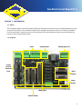
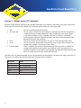
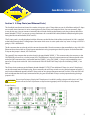
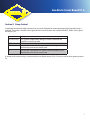
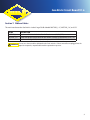
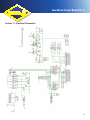
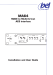
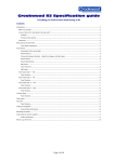
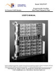
Geo Brick
Circuit Board V1.6
User Manual
WJ-D-M1011
022712
Geo Brick Circuit Board V1.6
Table of Contents
Section 1: Introduction........................................................................................................................................3
1.1 About
3
1.2 Diagram
3
Section 2: Voltage Inputs (X1 Connector)...........................................................................................................4
Section 3: E-Stop Chain (and Ethernet Ports).....................................................................................................5
Section 4: Limits...................................................................................................................................................6
Section 5: Pump Control......................................................................................................................................7
Section 6: Head Outputs......................................................................................................................................8
Section 7: Ribbon Cables.....................................................................................................................................9
Section 8: Comp Header......................................................................................................................................10
Section 9: Work Lights..........................................................................................................................................11
Section 10: Circuit Board Layout.........................................................................................................................12
Section 11: Electrical Schematics........................................................................................................................13
2
Geo Brick Circuit Board V1.6
Section 1: Introduction
1.1 About
The Geo Brick Interface Printed Circuit Board (PCB) was designed to ease the wiring and troubleshooting of a wide
variety of CNC machines. The Geo Brick Interface PCB is designed to connect to a 4 or 8-axis Delta Tau Geo Brick.
For most applications, machine wiring can be terminated to the interface board without any need for breakout
boards or messy terminal block wiring.
1.2 Diagram
Limits
Pump Control
E-Stop
Chain &
Ethernet
Ports
Voltage Inputs X1
Head
Outputs
Comp
Header
Work Lights
Ribbon Cables
3
Geo Brick Circuit Board V1.6
Section 2: Voltage Inputs (X1 Connector)
All power to the Geo Brick Interface PCB is brought in through a 5-pin Phoenix-style header in the upper right corner
of the board. The board itself is labeled with a short description of each pin. From right to left:
1. GND 2. 24 V No E-stop 3. COM 4. 24 V In 5. E-Stop Satisfied
This pin should be tied to Earth Ground
This pin sources 24 VDC when the machine is completely out of E-Stop. The operator is required to clear all of the mechanical E-Stops and then press the “reset” button in the software before 24 VDC is available at this pin. This source is suitable for powering external devices (solenoids, actuators, etc.) that should not be able to be operated under an E-Stop condition.
This pin is a 24 VDC common reference. Use this as a return for all 24 VDC wiring.
This pin is a 24 VDC source direct from a 24 VDC power supply. There will always be voltage here, regardless of the status of the E-Stop.
There is voltage at this terminal whenever the physical E-Stop chain is satisfied. This voltage needs applied to the Geo Brick abort input (X15-pin2) to prompt the user interface to show the “reset” button to the operator. This voltage should not be used to power any other external sources except the Geo Brick.
All of these pins are grouped together for ease of connection to terminal blocks near the power supply/Geo Brick. If a
wire harness is made up, the recommended colors for each wire are as follows:
Wire Label
GND
24V – No E-stop
COM
24V in
E-stop Satisfied
4
Color
Green with Yellow Stripe
Blue (or light Blue)
Blue with White Stripe
Red
Yellow
Geo Brick Circuit Board V1.6
Section 3: E-Stop Chain (and Ethernet Ports)
The Geo Brick interface circuit board also makes wiring up a series E-Stop chain easy to do. All of the machine’s E-Stops
are normally closed contacts in series, meaning that any one E-Stop can break the circuit. You can connect E-Stops
in one of two ways. You can connect a normally closed switch directly to the Phoenix style plug in the top left of the
board (labeled “E-STOPS”) or you can use two conductors of a standard RJ45 cable (Ethernet cable) through the jacks
facing the left side of the board (EOUT and E1).
The E-Stop’s path is visually displayed with the silkscreen on the left-hand side of the circuit board. 24 V IN is supplied
to the board through the X1-Voltage Input Connector which starts its series path at the “up” arrow. As long as 24 VDC is
going in, LED1 should be lit.
The first contact that must be closed is the one at the controller. Close the contact at the controller by using a WJ-1333
Ethernet infuser board with an E-Stop button attached to it or by jumpering out the JP2 jumper. Once the controller
E-Stop or the jumper is closed, LED 2 will be lit.
The second E-Stop contact that must be closed is the port labeled “SPARE_1”. This contact works the same way as the
CONTROLLER port and has a similar jumper (JP3). The difference is that you cannot connect an Ethernet device at the
end of an RJ45 connector that is connected into the “SPARE_1” plug. The “SPARE_1” plug is only intended for use as
part of an E-Stop chain with a WJ-1333 circuit board. LED3 will be lit if all E-Stops up to and including “SPARE_1” are
closed.
The E-Stop chain continues to the Phoenix header labeled “E-STOPS”. Two additional E-Stops (or series E-Stop loops)
can be connected into this Phoenix plug. Place a normally closed E-Stop switch or a wire jumper between terminals 1
and 2 and an additional normally closed E-Stop switch or wire jumper between terminals 3 and 4. LED4 and LED5 will
be lit to indicate that the E-Stops connected to this plug are closed. Both E-Stops can be jumpered out by placing a
jumper in JP5.
Do not install a jumper if a physical E-Stop button is installed. Installing a jumper while there is an E-Stop
! WARNING
! !
button will cause that E-Stop button to stop functioning properly which could pose a safety hazard.
E-stop Circuitry
*
5
Geo Brick Circuit Board V1.6
Section 4: Limits
The limits for a standard gantry are broken out through the Phoenix headers at the top of the board. Each limit switch
plug has 2 pins per switch and is intended to be used with a normally closed contact type of switch. One of the two
pins (labeled with a tiny “+”) sources 24 V out to the switch. Unless the switch is depressed, 24 V should return to the
other pin. When the limit switch is depressed, no voltage should be present at the other pin. In software, the state of
a limit switch can be seen in the homing screen represented by a light bulb. The light bulb will be lit up if the switch is
pressed; otherwise, the bulb will be off.
3-wire switches, such as inductive proximity switches, can be used instead of mechanical 2-wire switches. Since a 24
V common terminal is not located in the limit switch Phoenix plugs, the common wire needs to be tied in at another
location such as a terminal block. When using 3-wire switches, 24 V normally closed PNP (sourcing) switches should be
specified.
For the purpose of homing, X and Y axes have positive (+) overtravel and negative (-) overtravel limits as silkscreened
on the circuit board. The XX axis has only one switch which is used only for homing. Z+, Z-, A-home, and C-home
switches are distributed out of the DSUB connectors labeled “HEAD_1” and “HEAD_2”. A-home and C-home switches
can be specified as either PNP or NPN. Slider switch A-JP and B-JP should be in the correct position as indicated on the
silkscreening.
The circuit board is labeled assuming that the two parallel gantry axes are X and XX and that the crossbeam axis is Y.
Even if the two parallel axes are Y and YY, they should be plugged into the board in the X and XX positions.
6
Geo Brick Circuit Board V1.6
Section 5: Pump Control
A dedicated connector for digital outputs that are usually allocated for remote operation of the intensifier pump is
available. The header is located to the right of the limit switch headers and is labeled “REMOTE_PUMP”. From right to
left the pins are:
Name
24 V NO ESTOP
COM
ON
LP
Description
24 V signal for isolated relay. Voltage is removed whenever the
machine is in the E-Stop state
24 V return, useful for isolated relays mounted in pump control box
Pump On - Maintained 24 V output, useful for enabling a 24 V
isolated relay inside pump control panel
Low Pressure - Maintained 24 V output, useful for enabling a 24 V
isolated relay inside pump control panel
If remote pump control wiring is not required, the two digital outputs (ON, LP) can be used for other general purpose
I/O.
7
Geo Brick Circuit Board V1.6
Section 6: Head Outputs
Many of the I/O signals are terminated into the DSUB connectors labeled “HEAD_1” and “HEAD_2” for ease of wiring.
If wires are going to be distributed out using a WJ-1520 Z-Carriage circuit board, a WJ-1511 (Z-Carriage to Breakout
Board) cable assembly will connect the two. Otherwise, a WR-1008 (Z-carriage to pigtails cable) can be used to distribute these signals to terminal blocks.
WJ-1511 cable:
WR-1008 cable:
8
Geo Brick Circuit Board V1.6
Section 7: Ribbon Cables
The main interface to the Geo Brick is via the 3 large DSUBs labeled “MOTORS_1-4”, “MOTORS_5-8”, and “I/O”.
NAME
MOTORS_1-4
MOTORS_5-8
I/O
DESCRIPTION
Breaks out all limit switch wires for the first 4 motors (X, XX, Y, Z1)
Breaks out all limit switch wires for the second 4 motors (if applicable) (A, B/C, Z2)
Breaks out all digital I/O (16 inputs, 8 outputs, all 24 V PNP levels)
Do not cross the two cables dedicated to the limit switches. If these two cables are plugged into the
! WARNING
! !
opposite receptacles, unpredictable machine operation may occur.
*
9
Geo Brick Circuit Board V1.6
Section 8: Comp Header
The 4-pin connector at the bottom-right of the board can be used for laser compensation of a machine. A fast output
tied to the LP output causes a contact closure between Pins 1 and 3 of connector X3. When electronic compensation
has been completed, the output is no longer used during normal operation.
10
Geo Brick Circuit Board V1.6
Section 9: Work Lights
6 white LEDs are across the bottom of the circuit board. The LEDs can be turned on or off with the switch in the
bottom right corner of the board (A-JP1). These lights are intended to provide light for servicing the circuit board in
dark areas. During normal operation, the lights should be switched off.
11
Geo Brick Circuit Board V1.6
Section 10: Circuit Board Layout
12
Geo Brick Circuit Board V1.6
Section 11: Electrical Schematics
13