1
SGT-LD-5-23
LD IP Radio Link
User Manual
Copyright
Copyright © 2010 all rights reserved. No part of this publication may be reproduced, adapted, stored in a
retrieval system, translated into any language, or transmitted in any form or by any means without the
written permission of the supplier.
About This Manual
This user manual is intended to guide a professional installer to install the SGT-LD-5-23 and how to build
the infrastructure around it.
It includes procedures to assist you to avoid unforeseen problems.
Conventions
For your attention on important parts, special characters and patterns are used in this manual:
Note:
This indicates an important note that you must pay attention to.
Warning:
This indicates a warning or caution that you have to abide.
Bold: Indicates the function, important words, and so on.
Federal Communication Commission Interference Statement
This equipment has been tested and found to comply with the limits for a Class B digital device, pursuant
to Part 15 of the FCC Rules. These limits are designed to provide reasonable protection against harmful
interference in a residential installation.
This equipment generates uses and can radiate radio frequency
energy and, if not installed and used in accordance with the instructions, may cause harmful interference
to radio communications.
installation.
However, there is no guarantee that interference will not occur in a particular
If this equipment does cause harmful interference to radio or television reception, which can
be determined by turning the equipment off and on, the user is encouraged to try to correct the interference
by one of the following measures:
-
Reorient or relocate the receiving antenna.
-
Increase the separation between the equipment and receiver.
-
Connect the equipment into an outlet on a circuit different from that to which the receiver is connected.
-
Consult the dealer or an experienced radio/TV technician for help.
This device complies with Part 15 of the FCC Rules. Operation is subject to the following two conditions: (1)
This device may not cause harmful interference, and (2) this device must accept any interference received,
including interference that may cause undesired operation.
FCC Caution: Any changes or modifications not expressly approved by the party responsible for
compliance could void the user's authority to operate this equipment.
FCC Radiation Exposure Statement:
This equipment complies with FCC radiation exposure limits set forth for an uncontrolled environment.
To avoid the possibility of exceeding radio frequency exposure limits, you shall keep a distance of at
least 100cm between you and the antenna of the installed equipment.
This transmitter must not be
co-located or operating in conjunction with any other antenna or transmitter.
The availability of some specific channels and/or operational frequency bands are country
dependent and are firmware programmed at the factory to match the intended destination.
The firmware setting is not accessible by the end user.
Content
Chapter 1 Introduction ........................................................................................................................ 11
Introduction ........................................................................................................................................ 11
Appearance ....................................................................................................................................... 11
Key Features .................................................................................................................................... 12
Typical Applications .......................................................................................................................... 13
Telemedicine Wireless Broadband Application ............................................................................. 13
Education Wireless Broadband Application .................................................................................. 14
Chapter 2 Hardware Installation ....................................................................................................... 15
Preparation before Installation .......................................................................................................... 15
Professional Installation Required ................................................................................................ 15
Safety Precautions ........................................................................................................................ 16
Installation Precautions ................................................................................................................. 16
Product Package........................................................................................................................... 17
Hardware Installation ........................................................................................................................ 19
Assemble the Mounting Bracket ................................................................................................... 19
Pole Mounting ............................................................................................................................... 19
Interface Definition ........................................................................................................................ 21
Connect Up ................................................................................................................................... 23
Grounding ..................................................................................................................................... 24
Power On ...................................................................................................................................... 25
Chapter 3 Basic Settings ................................................................................................................... 27
Factory Default Settings ................................................................................................................... 27
System Requirements ...................................................................................................................... 28
How to Login the Web-based Interface ............................................................................................ 29
Basic System Setup ......................................................................................................................... 31
Basic Wireless Settings .................................................................................................................... 32
Chapter 4 Advanced Settings ........................................................................................................... 35
Advanced Wireless Settings ............................................................................................................. 35
Peer-to-Peer Links ............................................................................................................................ 37
Antenna Alignment Tool ................................................................................................................ 39
Link Test............................................................................................................................................ 40
Super Mode ...................................................................................................................................... 41
Wireless Security Settings ................................................................................................................ 42
Security Profile Configuration ....................................................................................................... 42
Access Control .............................................................................................................................. 44
RADIUS Settings .............................................................................................................................. 45
Chapter 5 Management...................................................................................................................... 47
View SGT-LD-5-23 Basic Information............................................................................................... 47
View Ethernet Statistics .................................................................................................................... 48
View Wireless Statistics .................................................................................................................... 49
Connection ....................................................................................................................................... 50
Password .......................................................................................................................................... 51
Remote Management ....................................................................................................................... 51
Remote Console ........................................................................................................................... 52
SNMP ............................................................................................................................................ 55
Time Settings .................................................................................................................................... 57
GPS Coordinate Settings ................................................................................................................. 57
Upgrade Firmware ............................................................................................................................ 58
Backup/Restore Settings .................................................................................................................. 60
Restore Factory Default Settings ..................................................................................................... 61
Event Log.......................................................................................................................................... 62
Reboot .............................................................................................................................................. 63
Chapter 6 Troubleshooting ............................................................................................................... 64
Appendix A. Channel – Frequency Table ......................................................................................... 66
Appendix B. Channel – Country List Table ..................................................................................... 68
Appendix C. ASCII .............................................................................................................................. 72
Appendix D. SSH Settings................................................................................................................. 73
Appendix E. GPL Declamation.......................................................................................................... 78
FIGURE
Figure 1 SGT-LD-5-23 ........................................................................................................................ 11
Figure 2 Telemedicine Wireless Broadband ........................................................................................ 13
Figure 3 Campus Wireless Broadband ................................................................................................ 14
Figure 4 Bracket Mounting – Step 1 ..................................................................................................... 19
Figure 5 Bracket Mounting – Step 2 ..................................................................................................... 19
Figure 6 Pole Mounting –Step 1 ........................................................................................................... 20
Figure 7 Pole Mounting – Step 2 .......................................................................................................... 20
Figure 8 Pole Mounting – Step 3 .......................................................................................................... 20
Figure 9 Interface Definition ................................................................................................................. 21
Figure 10 Detailed View of RS-232 Port .............................................................................................. 22
Figure 11 Warning Label ...................................................................................................................... 22
Figure 12 Vent ...................................................................................................................................... 23
Figure 13 Connect Up – Step 1 ............................................................................................................ 23
Figure 14 Connect Up – Step 2 ............................................................................................................ 23
Figure 15 Connect Up – Step 3 ............................................................................................................ 24
Figure 16 Connect Up – Step 4 ............................................................................................................ 24
Figure 17 Grounding ............................................................................................................................ 24
Figure 18 PoE Connection ................................................................................................................... 25
Figure 19 Security Alert ........................................................................................................................ 29
Figure 20 Login .................................................................................................................................... 29
Figure 21 Main Page ............................................................................................................................ 30
Figure 22 Basic Setup .......................................................................................................................... 31
Figure 23 Basic Wireless Settings ....................................................................................................... 32
Figure 24 Advanced Parameters ......................................................................................................... 35
Figure 25 Peer-to-Peer Links for CSMA .............................................................................................. 37
Figure 26 PTP/PTMP for TDMA ........................................................................................................... 38
Figure 27 Antenna Alignment Tool ....................................................................................................... 39
Figure 28 Link Test ............................................................................................................................... 40
Figure 29 Super Mode ......................................................................................................................... 41
Figure 30 Security ................................................................................................................................ 42
Figure 31 Access Control ..................................................................................................................... 44
Figure 32 RADIUS Settings ................................................................................................................. 45
Figure 33 Basic Information ................................................................................................................. 47
Figure 34 Ethernet Statistics ................................................................................................................ 48
Figure 35 Wireless Statistics ................................................................................................................ 49
Figure 36 Connection ........................................................................................................................... 50
Figure 37 Password ............................................................................................................................. 51
Figure 38 Remote Management .......................................................................................................... 52
Figure 39 PuTTY Configuration 1 ........................................................................................................ 53
Figure 40 PuTTY Configuration 2 ........................................................................................................ 54
Figure 41 SSH ...................................................................................................................................... 55
Figure 42 Obtain MIB File .................................................................................................................... 56
Figure 43 Time Settings ....................................................................................................................... 57
Figure 44 Upgrade Firmware ............................................................................................................... 58
Figure 45 Backup/Restore Settings ..................................................................................................... 60
Figure 46 Restore Settings .................................................................................................................. 61
Figure 47 Event Log ............................................................................................................................. 62
Figure 48 Reboot ................................................................................................................................. 63
TABLE
Table 1 PIN Definition ........................................................................................................................... 21
Table 3 RSSI-Beep Frequency .......................................................................................................... 40
Table 4 Channels in 5MHz Centre Frequency ..................................................................................... 66
Table 5 Channels in 10MHz Centre Frequency ................................................................................... 66
Table 6 Channels in 20MHz Centre Frequency ................................................................................... 67
Table 7 Channels in 40MHz Centre Frequency ................................................................................... 67
Table 8 Country of FCC........................................................................................................................ 68
Table 9 Country of European Union ..................................................................................................... 69
Table 10 Other Countries ..................................................................................................................... 70
Table 11 ACSII ...................................................................................................................................... 72
Table 12 SSH Settings ......................................................................................................................... 73
Table 13 Public Software Name and Description ................................................................................. 79
Chapter 1 Introduction
Introduction
Designed for an outdoor environment application, the SGT-LD-5-23 is a high-performance
outdoor-deployable wireless bridge that provides wireless connectivity among multiple network
locations. The SGT-LD-5-23 has a built-in 23dBi flat panel antenna that can deliver data at distances
in excess of 40km.
The SGT-LD-5-23 is a multi function communication device that supports Base Station, CPE, PTP
and PTMP mode connectivity.
It allows for local area network‟s (LANs) in different locations
(buildings) to be easily interconnected.
The SGT-LD-5-23 LD delivers “last mile” broadband
connectivity through its PTP and PTMP capabilities.
With high throughput and long-distance transmission capabilities, the SGT-LD-5-23 is an ideal
backhaul solution for Carriers, Enterprises and Service Providers.
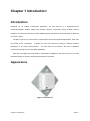
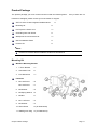
Appearance
Figure 1 SGT-LD-5-23
Chapter 1 Introduction
Page 11
Key Features
Provide easy installation and high performance wireless connectivity of up to 50km
IP67 waterproof housing endures almost any harsh environments
Multiple operating modes including Base station, CPE, PTP and PTMP
Support 64/128-bit WEP and 802.1X, WPA-PSK, WPA2-PSK and WPA-PSK&WPA2-PSK, etc.
Supports WMM and Quality of Service (QoS) for enhanced performance
Proprietary Antenna Alignment Tool helps identify the antenna orientation with the best signal
strength
Buzzer design helps to determine the device power initial condition
Super mode to boost the data rate up to 108Mbps
Advanced management tools like SNMP and Secure Shell (SSH)
User-friendly Web, SSH and SNMP-based management interface
Chapter 1 Introduction
Page 12
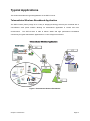
Typical Applications
This section describes the typical applications of the SGT-LD-5-23.
Telemedicine Wireless Broadband Application
The SGT-LD-5-23 primary usage is as a relay or bridging technology that may be combined with a
cost-effective solar power solution allowing for telemedicine application in remote and rural
environments.
The SGT-LD-5-23 is able to deliver stable and high performance broadband
connectivity for typical telemedicine applications in a Line-of-Sight environment.
Figure 2 Telemedicine Wireless Broadband
Chapter 1 Introduction
Page 13
Education Wireless Broadband Application
Schools in remote or rural areas can be provided with broadband connectivity via local Internet service
providers.
The relay ability of the SGT-LD-5-23 allows for multiple hops to be made thus allowing the
SGT-LD-5-23 to reach more remote LOS locations beyond 40km or to circumvent natural obstructions
like mountains.
Figure 3 Campus Wireless Broadband
Additionally, the SGT-LD-5-23 can also be applied for the following environments:
Cost-effectively provide long distance backhaul for remote areas (e.g. village, oil well, island,
mountain etc.)
Establish local backhaul for campus, farm and factory
Provide access for video streaming or surveillance for industrial and mining enterprises
Operates as a relay connecting different networks
Chapter 1 Introduction
Page 14
Chapter 2 Hardware Installation
This chapter describes safety precautions and product information you have to know and check before
installing a SGT-LD-5-23.
Preparation before Installation
Professional Installation Required
1.
Please seek assistance from a professional installer who is well trained in the RF installation and
knowledgeable regarding the local regulations.
2.
The SGT-LD-5-23 is provided through distribution to system installers who employ services of
trained professional technicians – the SGT-LD-5-23 is not sold directly through retail stores.
3.
The equipment shall be installed in RESTRICTED ACCESS LOCATIONS.
Access can only be
gained by service persons or by users who have been instructed about the reasons for the
restrictions applied to the location and about any precautions that shall be taken.
Furthermore,
access is through the use of a tool or lock and key, or other means of security, and is controlled
by the authority responsible for the location.
4.
If you are intended to use an external antenna with the SGT-LD-5-23, please contact your
supplier/installer to ensure that your unit is set for you have fulfilled all the local regulatory
requirements.
It is the responsibility of the installer/user to check that the equipment as
deployed meets local regulatory requirements.
Chapter 3 Basic Settings
Page 15
Safety Precautions
To ensure your safety and to install the hardware properly, please read and follow these safety
precautions.
ONLY qualified service personnel should service or disassemble this device;
When installing the device, note the followings:
-
Do NOT use a metal ladder;
-
Do NOT work on a windy or raining day;
-
Do NOT install, use or service the device during a thunderstorm, as this may cause a remote
risk of electric shock from lightning;
-
Wear shoes with rubber soles and heels, rubber gloves, long sleeved shirt or jacket.
-
When the system is operational, avoid standing directly in front of the antenna. Strong RF
fields are present when the transmitter is on.
Ground the device properly with grounding wire to protect against lightning;
Use ONLY appropriate accessories for the device.
If the temperatures of the unit surface exceeds the limit, be precautious not to continuous hold or
touch the device for a certain period of time.
Installation Precautions
To keep the SGT-LD-5-23 well while you are installing it, please read and follow these installation
precautions.
1. Users MUST use a proper and well-installed surge arrestor and grounding kit with SGT-LD-5-23;
otherwise, a random lightning could easily cause fatal damage to SGT-LD-5-23.
EMD
(Lightning) DAMAGE IS NOT COVERED UNDER WARRANTY.
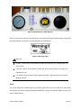
2. Make sure PoE is correctly connected to the RJ-45 port on the SGT-LD-5-23 labelled PoE+Data.
DO NOT CONNECT TO THE PORT LABELED “Warning!! No POE”,
otherwise the
SGT-LD-5-23 will be severely damaged!
Chapter 3 Basic Settings
Page 16
Product Package
The product package you have received should contain the following items.
If any of them are not
included or damaged, please contact your local vendor for support.
×1
SGT-LD-5-23 LD with integrated 23dBi antenna
Mounting Kit
×1
PoE Injector & Power cord
×1
Grounding Wire with Screw
×1
Waterproof RJ-45 Connector Kit
×1
Quick Installation Guide
×1
Product CD
×1
Note:
Product CD contains Quick Installation Guide and User Manual
Mounting Kit
Wall/Pole Mounting Bracket
1. T-Form Bracket
×1
2. Articulation Pole
×1
3. Pole Mount Bar
×1
Fasteners
4. M8×80 Screw
×2
M8×90 Screw
×1
5. M8 Washer
×3
6. M8 Spring Washer ×3
7. M8 Nut
×1
8. M5×16 Screw
×4
9. M5 Washer
×4
10. Wood Screw
×4 (for Wall Mount)
11. Wall/Gyprock Plug ×4 (for Wall Mount)
Chapter 3 Basic Settings
Page 17
Waterproof RJ-45 Connector Kit
1. Gland
×1
2. Sealing Nut
×1
3. Sealing
×1
Chapter 3 Basic Settings
Page 18
Hardware Installation
Assemble the Mounting Bracket
1.
Place the main bracket into the seating and use a spanner to fasten the bracket to the
SGT-LD-5-23 with M5×16 screws ⑧ and M5 washers ⑨ provided in the hardware packets;
Figure 4 Bracket Mounting – Step 1
2.
Assemble the main bracket by placing articulation pole ② to the T-form bracket ① via a
M8×90 ④ screw through the insertion axe and fix with the M8 washer ⑤ , spring washer ⑥
and M8 nut⑦;
Figure 5 Bracket Mounting – Step 2
Pole Mounting
1.
Install the main bracket and the pole mount bar ③ over the top of the pole by securing the drill
holes of the pole mount bar to the main bracket ones and insert two M8×80 ④ screws, spring
washers ⑥ and washers ⑤ through the drill holes and main bracket;
Chapter 3 Basic Settings
Page 19
Figure 6 Pole Mounting –Step 1
2.
Fasten two M8×80 screws ④ and washers ⑤ through the drill holes and main bracket with a
spanner;
Figure 7 Pole Mounting – Step 2
3.
Adjust the antenna for appropriate tilt / vertical orientation.
Figure 8 Pole Mounting – Step 3
Note:
The horizontal and vertical beam width of SGT-LD-5-23 default antenna is about 10
degree respectively.
Chapter 3 Basic Settings
Page 20
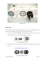
Interface Definition
The SGT-LD-5-23 currently provides two interfaces at the bottom, which are PoE + Data with a black
plastic cover and RS-232 with a light gray cover that label “WARNING! No PoE”. Amongst which, a
black RJ45 waterproof connector will be provided for the PoE + Data interface.
Figure 9 Interface Definition
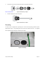
RS-232
RS-232, which is labeled COM/RESET, is used for debugging purposes as well as for a hard reset of
the SGT-LD-5-23.
Below, you may find the pin definition of the RS-232.
Table 1 PIN Definition
Pin Assignment
Name
Description
P1
TXD0
Data Transmit 0
P2
DSR0
Data Set Ready 0
P3
RXD0
Data Receive 0
P4
TXD1
Data Transmit 1
P5
RXD1
Data Receive 1
P6
DTR1
Data Terminal Ready
P7
Hard Reset
Hard reset the unit
P8
GND
Ground
To reset the device, short P7 (Hard Reset) to P8 (GND) for less than 1 second and the system will
reset.
If P7 (Hard Reset) is shorted to P8 (GND) for over 5 seconds, the SGT-LD-5-23 LD will be
reset to the factory default settings.
Chapter 3 Basic Settings
Page 21
Figure 10 Detailed View of RS-232 Port
Above are the views of RS-232 cover and RJ-45 port respectively, please note the label coverings and
DO strictly follow the instructions to avoid damaging your equipment!
Figure 11 Warning Label
Warning:
Do NOT connect PoE powered Ethernet cable to the RS-232 port; otherwise the port
may burnout!
If RS-232 cable is used outdoors, please DO add a surge protector to protect the
equipment circuit!
It is strongly recommended to add a lightning arrestor on the RS-232 port to prevent
lightning damage.
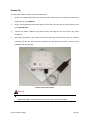
Vent
The vent is designed to facilitate vapor and moisture egress out of the unit as well as to repel water,
dust and dirt by using the specially designed membrane, thereby preventing the SGT-LD-5-23 from
electric malfunctioning.
Chapter 3 Basic Settings
Page 22
Vent
Figure 12 Vent
Connect Up
Before installing the Ethernet cable with a waterproof RJ-45 connector, it is recommended that the
Cat-5 RJ-45 coaxial cable be used for the SGT-LD-5-23 to power PoE connector.
1.
To connect to the hole labelled PoE+Data, open the black cover in advance by using a coin or a
slotted screwdriver and then screw in the body of the gland and tighten.
Figure 13 Connect Up – Step 1
2.
Slide the sealing nut to the RJ-45 cable from its middle breach and then insert the sealing into
the cable.
Slide the Sealing Nut from its Breach
Figure 14 Connect Up – Step 2
Chapter 3 Basic Settings
Page 23
3.
Insert the RJ-45 connector and make sure that the locking tab snaps home.
SGT-LD-5-23 RJ-45 Port
4.
Figure 15 Connect Up – Step 3
Screw the sealing on the gland and tighten.
Figure 16 Connect Up – Step 4
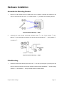
Grounding
The SGT-LD-5-23 is shipped with a grounding wire. The unit must be properly grounded to protect
against power surges.
The grounding point can be found on the bottom of the unit.
It is supplied
with an appropriate grounding lug for attachment to the ODU.
Figure 17 Grounding
Chapter 3 Basic Settings
Page 24
Power On
To power up the SGT-LD-5-23, follow the steps below:
1.
Plug a user-supplied Cat-5 Ethernet cable from your wired LAN (or a computer) into the power
injector RJ-45 jack (DATA IN);
2.
Plug a user-supplied Cat-5 Ethernet cable from the SGT-LD-5-23 into the power injector RJ-45
jack (P+DATA OUT);
3.
Connect the power module to the power injector and plug the AC cord into an AC power
receptacle;
4.
After being powered on, the device will send out the beep sound lasting about 1.5 seconds,
informing you that the SGT-LD-5-23 is powered up! Wait about 60 seconds - system will be
initialized and start working.
Figure 18 PoE Connection
Warning:
Make sure the PoE is correctly connected to the RJ-45 port to the SGT-LD-5-23
labelled PoE+Data, otherwise the SGT-LD-5-23 will be severely damaged!
Chapter 3 Basic Settings
Page 25
Chapter 3 Basic Settings
Page 26
Chapter 3 Basic Settings
Factory Default Settings
We‟ll elaborate the SGT-LD-5-23 factory default settings. You can re-acquire these parameters by
default.
If necessary, please refer to the “Restore Factory Default Settings”.
Table 2 SGT-LD-5-23 Factory Default Settings
Features
Factory Default Settings
Username
Admin
Password
Password
Wireless Device Name
DEVICEXXXXXX (X represents the
last 6 digits of Ethernet MAC
address)
Operating Mode
Peer-to-Peer (CSMA)
Country/Region
United States (Country dependent
and software programmed)
Ethernet Data Rate
LAN
Automatic
IP Address
192.168.1.1
Subnet Mask
255.255.255.0
Gateway
0.0.0.0
Primary DNS Server
0.0.0.0
Secondary DNS Server
0.0.0.0
DHCP Client
Disable
Spanning Tree
Enable
Wireless Mode
802.11a
Channel/Frequency
149/5.745GHz (CE: 100/5.5GHz)
BSSID
wireless
Transmit Rate
Best
Output Power
100% (Full)
Bandwidth
20MHz
TDM Coordination
Disable
WMM
Disable
Super Mode
Disable
RTS Threshold (byte)
2346
Fragmentation Length (byte)
2346
Beacon Interval
100
Distance in Meters
10000
Security
Open System
Chapter 3 Basic Settings
Page 27
Encryption
None
Wireless Client Isolation
Disable
Access Control
Disable
SSH (Secure Shell)
Enable
SNMP
Enable/Disable
Enable
Read Community Name
Public
Write Community Name
Private
IP Address
0.0.0.0
System Requirements
Before configuration, please make sure that your system meets the following requirements:
A computer coupled with 10/100 Base-TX adapter;
Configure the computer with a static IP address of 192.168.1.x, as the default IP address of
SGT-LD-5-23 is 192.168.1.1, X cannot be 0, 1, nor 255;
A Web browser on PC for configuration such as Microsoft Internet Explorer 6.0 or above or
Firefox.
Chapter 3 Basic Settings
Page 28
How to Login to the Web-based Interface
The SGT-LD-5-23 provides you with user-friendly Web-based management tool.
Open IE and enter the default IP address (Default: 192.168.1.1) of the SGT-LD-5-23 into the
address field.
sites”.
A Security Alert window may popup as below, due to browser‟s security “trusted
You may choose to continue to the login webpage.
Figure 19 Security Alert
Clicking “Yes” will usher you into the login page:
Figure 20 Login
Enter the username (Default: admin) and password (Default: password) respectively and click
“Login Now” to login to the main page of the SGT-LD-5-23.
As you can see, this management
interface provides four main options in the black bar above, which are System, Wireless, Status
and Management.
Chapter 3 Basic Settings
Page 29
Figure 21 Main Page
Note:
The username and password are case-sensitive, and the password is no more than
19 characters!
Chapter 3 Basic Settings
Page 30
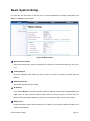
Basic System Setup
For users who use this device for the first time, it is recommended that you begin configuration from
“Basic” in “System” shown below:
Figure 22 Basic Setup
Wireless Device Name
Specify the device name, which is composed of no more than 15 characters with (0-9), (A-Z), (a-z)
or (-).
Country/Region
Since the available radio bands vary from country to country, the working channels used are
different.
Ethernet Data rate
Specify the transmission rate of data.
IP Address
If you select “Manual”, you have to specify a static IP address, subnet mask, default gateway and
DNS server for your local area network which connects to the LAN port of the SGT-LD-5-23.
Make sure the specified IP address is unique on your network in order to prevent IP conflict.
DHCP Client
Enable the DHCP client to allow the DHCP server within your local area network to assign an IP
address automatically.
Chapter 3 Basic Settings
Page 31
Spanning Tree Protocol (STP)
Spanning Tree Protocol is a link management protocol for SGT-LD-5-23 bridges which provides
path redundancy while preventing loops in a network. STP allows only one active path at a time
between the SGT-LD-5-23 bridges but establish the redundant link as a backup if the initial link
fails.
STP Forward Delay
STP Forward Delay is the time spent in detecting and learning network tree topology state before
entering the forward state. Default time value is 1 sec. Select Normal if you would like to modify
the parameter (4-30 seconds).
Basic Wireless Settings
Open “Radio” in “Wireless” as below to make basic wireless configuration.
Figure 23 Basic Wireless Settings
Operating Mode
Four operating modes are available on the SGT-LD-5-23.
In a point to point environment where
there are only two radios, Peer to Peer is recommended as it works more efficiently.
Base Station: The SGT-LD-5-23 connects directly to the main Ethernet LAN and receives
connectivity from other wireless devices.
CPE: The SGT-LD-5-23 connects to a remote LAN and the Base Station in it.
Chapter 3 Basic Settings
Page 32
Peer-to-Peer (CSMA): The SGT-LD-5-23 connects to another wireless device within the same
network using CSMA protocol.
at any one time.
CSMA ensures that only one node is transmitting on the network
Under this mode, both PTP and PTMP are available.
It is highly
recommended to use this mode when the distance between two nodes is less than 20km.
Peer-to-Peer (TDMA): The SGT-LD-5-23 connects to another wireless device within the same
network using TDMA protocol. TDMA divides each channel into multiple time slots to increase the
amount of data that can be carried; hence increase the throughput. Under this mode, only PTP is
available and is suggested to use this mode when the distance between the two SGT-LD-5-23‟s is
greater than 20km.
Base Station ID (SSID)
For Base Station mode, it requires SSID for CPE clients to associate with.
name is shared among all associated devices in your wireless network.
those devices.
This wireless network
Keep it identical on all of
Note that the SSID is case-sensitive and cannot exceed 32 characters.
Wireless Mode
The SGT-LD-5-23 can only communicate with wireless devices using 802.11a.
Channel/Frequency
Channels varies much as the available band differs from country to country.
Select a proper
operating channel in the drop-down list according to your situation.
Transmit Rate
Usually “Best” is preferred. Under this rate, the SGT-LD-5-23 will automatically select the highest
available rate to transmit.
In some cases, however, like where there is no great demand for
speed, you can have a relatively-low transmit rate as a compromise for achieving a long distance
link.
Output Power
Specify the signal transmission power.
The higher the output power is, the longer distance the
signal can cover, but the power consumption will be then be greater, accordingly. Usually “100%”
is preferred.
Band Width
Four bandwidths are available: 5MHz, 10MHz, 20MHz and 40MHz.
Among them, 40MHz can
enhance the data rate more effectively, but will use more bandwidth, thus cause possible
Chapter 3 Basic Settings
Page 33
interference.
TDM Coordination
Stands for “Time-Division Multiplexing” technique; this resource reservation control mechanism
can avoid packet collisions and send the packets much more efficiently allowing for higher
effective throughput rates.
This function is only available in CSMA BS and CPE mode.
this function on both BS and CPE devices.
Enable
It is highly recommended to enable TDM
coordination when there are multiple CPEs needing to connect to the BS in your application.
NoACK
Under TDMA mode, enabling NoACK can enhance throughput, but it might result in higher error
rates in a noisy environment.
WMM
WMM (Wi-Fi Multimedia) is a subset of 802.11e.
It allows wireless communication to define a
priority limit on the basis of data type, thus time-sensitive data, like video/audio data, may have a
higher priority than a common data type.
To enable WMM, the wireless client should also
support it.
Super Mode
Super mode is an effective way to enhance performance.
It can boost the transmission data rate
up to 108Mbps. The SGT-LD-5-23 provides you with three kinds of Super mode, which are Fast
Frame, Burst and Compression.
To enable Super Mode, the remote SGT-LD-5-23 should also
have this function enabled. For more information you may refer to Super Mode in Chapter 4
Advanced Settings.
Chapter 3 Basic Settings
Page 34
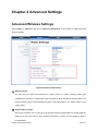
Chapter 4 Advanced Settings
Advanced Wireless Settings
Open “Radio” in “Wireless” and turn to “Advanced Parameters” at the bottom to make advanced
wireless settings.
Figure 24 Advanced Parameters
RTS Threshold
The SGT-LD-5-23 sends RTS (Request to Send) frames to certain receiving station and
negotiates the sending of a data frame. After receiving an RTS, that STA responds with a CTS
(Clear to Send) frame to acknowledge the right to start transmission. The setting range is 0 to
2346 in bytes.
Fragmentation Length
Specify the maximum size in bytes for a packet before data is fragmented into multiple packets.
Setting it too low may result in poor network performance. Leaving it at its default of 2346 is
recommended.
Chapter 4 Advanced Settings
Page 35
Beacon Interval
Specify the frequency interval to broadcast packets.
Enter a value between 20 and 1000.
Distance in Meters
To decrease the chances of data retransmission at long distance, the SGT-LD-5-23 can auto
adjust for proper ACK timeout value by specifying distance of the two nodes.
10Km.
Default distance is
This is only useful for CSMA mode.
TDM Coordination Time Slice
Specify the time slice for TDM Coordination.
It allows a certain amount of time (in ms) that data
will transmit to each other before it moves to the next user.
This is a repetitive cycle.
Note:
We strongly recommended you leave most advanced settings at their defaults except
Distance in Meters; any modification on them may negatively impact the performance
of your wireless network.
Chapter 4 Advanced Settings
Page 36
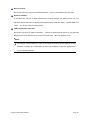
Peer-to-Peer Links
Open “Peer-to-Peer Setup” in “Wireless”.
Peer-to-Peer Links allow establishing PTP or PTMP
connectivity with at most four remote wireless devices; this feature only available under Peer-to-Peer
(CSMA) mode.
Figure 25 Peer-to-Peer Links for CSMA
To setup a Peer-to-Peer link, first login to the Web-based interface of the remote SGT-LD-5-23,
open “About” in “System” and record its wireless MAC address.
Then, login to the Web-based interface of the local SGT-LD-5-23 and open “Peer-to-Peer Setup”
in “Wireless”, input the WLAN MAC address of the remote one to “Remote MAC Address 1” field
and click “Apply”;
To check if the link has been successfully established, you may use ping to justify.
Chapter 4 Advanced Settings
Page 37
The other way to establish PTMP connectivity is to setup the same group id under “Radio” in
“Wireless”.
This feature only available under Peer-to-Peer (TDMA) mode and only devices with the
same Group ID can communicate.
Figure 26 PTP/PTMP for TDMA
Note:
When establishing a PTMP network, make sure all the remote wireless devices are
within the antenna beam width.
Chapter 4 Advanced Settings
Page 38
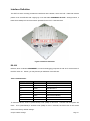
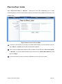
Antenna Alignment Tool
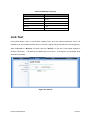
Under Peer-to-Peer (CSMA) mode, the Antenna Alignment Tool is available.
This function helps to
point in the approximate direction of the remote SGT-LD-5-23 antenna and assists the user to easily
align the local antenna to achieve maximum signal strength.
Figure 27 Antenna Alignment Tool
To use “Antenna Alignment Tool”, follow the steps below:
Open “Peer-to-Peer Setup” and select “RF1” or “RF2”.
bridge and click on the Apply button.
Enter the MAC address of the remote
Then click the “Align Antenna” button and the “Antenna
Alignment Tool” window will popup.
Set the target RSSI (e.g. -70dBm) and click “Start” button.
Wait about 5 seconds; the antenna alignment starts and performs alignment every one second.
Fix the local antenna and adjust the remote antenna elevation and horizontal direction.
the adjustment, observe “Current RSSI” in the local SGT-LD-5-23.
second.
During
The value will refresh every 1
Fix the remote antenna when it reaches your expectation.
Usually, a RSSI between
-60 and -70dBm indicates rather good signal strength.
Adjust the local antenna after fixing the remote one.
During the adjustment, observe the
“Current RSSI” in the remote SGT-LD-5-23. Fix the local antenna when it reaches your
expectation.
During the antenna alignment, the SGT-LD-5-23 will issue beep sound to indicate current RSSI.
Frequency of beep indicate the following RSSI:
Chapter 5 Management
Page 39
Table 3 RSSI-Beep Frequency
RSSI
Beep Frequency
>-50
100 /sec
-50~-60
50 /sec
-60~-70
5 /sec
-70~-80
2 / sec
-80~-90
1 /sec
< -90
No beep sound
Link Test
Under Base Station, CPE or Peer-to-Peer (TDMA) mode, when the Antenna Alignment Tool is not
available, Link Test provides another option to check the signal strength towards the connecting device.
Open “Link Test” in “Wireless” as below, and click “Refresh” to view the current signal strength of
wireless connectivity.
The table will be updated every 3 seconds.
If the signal is as calculated, align
the antenna manually.
Figure 28 Link Test
Chapter 5 Management
Page 40
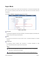
Super Mode
Super mode is an effective way to enhance the Wi-Fi performance; it can boost the transmission data
rate.
SGT-LD-5-23 provides you with three kinds of Super mode, which are Fast Frame, Burst and
Compression.
Open “Radio” in “Wireless”, Super Mode is in the red box as below:
Figure 29 Super Mode
Fast Frame
By utilizing frame aggregation and timing modifications, it increases throughput by transmitting more
data per frame and removing inter-frame pauses.
Burst
By allowing more data frames per given period of time, it increases throughput by overhead
reduction.
Compression
By performing real-time hardware data compression, it increases throughput by using
pre-compressed frames with no impact on the host processor.
Note:
Only if all of the wireless devices share the same wireless connectivity i.e. all supporting
Super mode, can this function be available!
The throughput may vary depending on the actually environment and data traffic flow.
Chapter 5 Management
Page 41
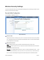
Wireless Security Settings
To prevent unauthorized radios from accessing data transmitting over the radio link(s), the SGT-LD-5-23
provides you with solid security settings.
Security Profile Configuration
Open “Security” in “Wireless” as below:
Figure 30 Security
Broadcast SSID
Hiding network name is necessary when you are in a wireless environment that may have potential
risk. By using this function, the STA cannot scan and find SGT-LD-5-23, so that a malicious attack
by some illegal STA can be avoided.
Network Authentication
Open: It allows any device to join the network, without performing any security check.
Shared Key: Data encryption and key are required for wireless authentication before association.
(Only available in BS and CPE mode).
WPA-PSK: It is a simplified WPA mode with no need for a specific authentication server.
In this
so-called WPA Pre-Shared Key mode, all you have to do is pre-enter a key in each WLAN node this is a common method adopted in large and mid-sized enterprises and residential networks.
Chapter 5 Management
Page 42
WPA2-PSK: As a new version of WPA, only if all the clients support WPA2, can it be available. If it is
selected, the data encryption can only be AES and the passphrase is required.
WPA-PSK&WPA2-PSK: It provides options of WPA (TKIP) or WPA2 (AES) encryption for the client.
If it is selected, the data encryption can only be TKIP + AES and the passphrase is required.
Data Encryption
If data encryption is enabled, the key is required and only through sharing the same key with other
wireless devices can the communication be established.
None: Available only when the authentication type is open system.
64 bits WEP: It is made up of 10 hexadecimal numbers.
128 bits WEP: It is made up of 26 hexadecimal numbers.
152 bits WEP: It is made up of 32 hexadecimal numbers.
TKIP: Temporal Key Integrity Protocol, which is a kind of dynamic encryption, is co-used with
WPA-PSK, etc.
AES: Advanced Encryption Standard, it is usually co-used with WPA2-PSK, WPA, WPA2, etc.
TKIP + AES: It allows for backwards compatibility with devices using TKIP.
Wireless Client Isolation Mode
Enabling this mode can prevent the communication between connected wireless clients.
Note:
We strongly recommend you enable wireless security on your network!
Only by setting the same Authentication, Data Encryption and Key in the
SGT-LD-5-23 and other wireless devices that connect with it, can the communication
be established.
Chapter 5 Management
Page 43
Access Control
The Access Control allows a STA to access a SGT-LD-5-23; thus, a further security mechanism is
provided.
This function is available only under Base Station mode.
Open “Access Control” in “Wireless” as below, check “Turn Access Control On” to enable this
function.
Figure 31 Access Control
Available CPEs
This table lists the CPEs currently connecting to the SGT-LD-5-23.
Check the box before each
MAC address, click “Add” to add one or more available CPE(s) into the “Trusted CPEs” and click
“Apply” to save settings.
Add New CPE Manually
Enter the MAC address of the CPE that you would like to list into the access control list, click “Add”,
then the CPE will be added into the “Trusted CPEs”.
Trusted CPEs
Check the box before one or more MAC addresses of CPEs that you would like to cancel and click
“Delete” to cancel that access control rule.
Chapter 5 Management
Page 44
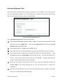
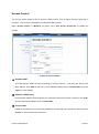
RADIUS Settings
RADIUS (Remote Authentication Dial-In User Service) is a server for remote user authentication and
accounting; RADIUS plays a central role in the network for providing the capabilities of authenticating,
authorizing, accounting, auditing, alarming and etc.
It allows an organization to maintain user profiles in
a central database that all remote servers can share.
Open “RADIUS Settings” in “System” to make RADIUS configuration.
Figure 32 RADIUS Settings
Authentication/Access Control RADIUS Server Login
This is for RADIUS authentication.
Number and Shared Secret.
It can communicate with RADIUS through IP Address, Port
If the Primary RADIUS fails to work, the Secondary RADIUS Server
is an option.
IP Address: Enter the IP address of the Radius Server;
Port Number: Enter the port number of the Radius Server;
Shared Secret: This secret, which is composed of no more than 31 characters, is shared by the
SGT-LD-5-23 and RADIUS during authentication.
Chapter 5 Management
Page 45
Advanced WPA/802.1X Parameters
Re-authentication Time: Set the time interval between two authentications.
Global-Key Update: Check this option and specify the time interval between two global-key
updates.
Chapter 5 Management
Page 46
Chapter 5 Management
View SGT-LD-5-23 Basic Information
Open “About” in “System” to check the basic information of the SGT-LD-5-23, which is read-only.
Figure 33 Basic Information
Chapter 5 Management
Page 47
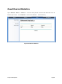
View Ethernet Statistics
Open “Ethernet Status” in “Status” to check the data packets received and transmitted from the
Ethernet port in LAN.
Click “Refresh” to view current statistics.
All are read-only.
Figure 34 Ethernet Statistics
Chapter 5 Management
Page 48
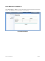
View Wireless Statistics
Open “Wireless Status” in “Status” to check the data packets received and transmitted via the wireless
network.
Click “Refresh” to view current statistics.
All are read-only.
Figure 35 Wireless Statistics
Chapter 5 Management
Page 49
Connection
Open “Connection” in “Status” to check the information of remote CPE‟s connected to the bridge; these
values also help determine if the antenna is aligned in an appropriate direction.
updated every 30 seconds.
The table will be
All are read-only.
Figure 36 Connection
Chapter 5 Management
Page 50
Password
From “Change Password” in “Management”, you can change the default password to manage your
SGT-LD-5-23.
Figure 37 Password
Change Password
For security purposes, you have to enter the current password first and then enter the new one
twice respectively in the “New Password” and “Repeat New Password” fields.
Restore Default Password
If you would like to restore the default password, enter the current password first and then check
“Yes” and click “Apply” to default the password.
Note:
The password is case-sensitive and its length cannot exceed 19 characters!
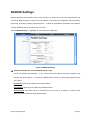
Remote Management
The SGT-LD-5-23 provides you with two more options for device management, which are SSH (Secure
Shell) and SNMP.
Chapter 5 Management
Page 51
Open “Remote Management” in “Management” to configure the remote management of the
SGT-LD-5-23.
Figure 38 Remote Management
Remote Console
The SGT-LD-5-23 supports CLI management, which can be accessed by Secure Shell (SSH).
It is
recommended that PuTTY be used to login. Download it from http://www.putty.org/ for free. The
minimum system requirement for using PuTTY is Windows 95, 98, ME, NT, 2000, XP and Vista on Intel
x86.
Follow the steps below to implement:
Once the program is downloaded, open up by double-clicking
. Note that before using
PuTTY, be sure that you are able to connect to the SGT-LD-5-23.
Enter IP Address of the SGT-LD-5-23 (Default: 192.168.1.1), Port (22) and check SSH as
connection type;
Chapter 5 Management
Page 52
Figure 39 PuTTY Configuration 1
Chapter 5 Management
Page 53
From “Connection” in the left menu bar, click “SSH”; select “2” as “Preferred SSH protocol
version”; make “3DES” the top position in “Encryption cipher selection policy”;
Figure 40 PuTTY Configuration 2
Click “Open”, a window as below will popup:
Chapter 5 Management
Page 54
Figure 41 SSH
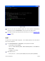
Enter the user name and password (Default user name/ password: admin/password)
respectively, you will see “DEVICE123456>”, which is the name of the SGT-LD-5-23;
Enter “help” command to get setting information; alternatively, you can refer to Appendix C. SSH
Settings for details.
SNMP
The SGT-LD-5-23 supports SNMP management.
Set the SNMP parameters and obtain MIB file
before remote management.
From “Remote Management” in “Management”, set the parameters for SNMP:
-
Enable SNMP by checking “Enable”;
-
Specify the “Read Community Name”, “Write Community Name” and “IP Address to
Receive Traps”
-
Hit “Apply” to save settings.
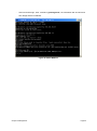
Obtain MIB file via FTP:
-
Enter ftp 192.168.1.1 , username (Default: admin) and password (Default: password);
Chapter 5 Management
Page 55
-
After successful login, enter command “get bridge.mib”, the information will as below and
then bridge.mib file is obtained.
Figure 42 Obtain MIB File
Chapter 5 Management
Page 56
Time Settings
Compliant with NTP, the SGT-LD-5-23 is capable of keeping its time in complete accord with Internet
time.
Make configuration in “Basic” from “System”:
Figure 43 Time Settings
Enter the time server IP address and port respectively in “Time Server” and “Time Server Port”
fields;
Select your desired time zone from the drop-down list, check “Adjust for Daylight Saving
Time” if necessary;
Hit “Apply” to save settings.
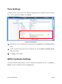
GPS Coordinate Settings
The GPS Coordinate Setting helps you mark the latitude and longitude of the LD.
From Basic in
System, enter the coordinates and click the Apply button.
Chapter 5 Management
Page 57
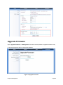
Upgrade Firmware
Open “Upgrade Firmware” in “Management” and follow the steps below to upgrade firmware locally
or remotely through the SGT-LD-5-23‟s Web interface:
Figure 44 Upgrade Firmware
Chapter 5 Management
Page 58
Click “Browse” to select the firmware file;
Click “Upload” to load the file into the SGT-LD-5-23;
Wait a moment, the system will reboot after successfully upgrade.
Note:
Do NOT cut the power off during the upgrade, otherwise the system may crash!
Chapter 5 Management
Page 59
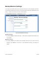
Backup/Restore Settings
It is strongly recommended to back up the configuration information in case of something unexpected.
If an unforeseen problem hits your device, you may have access to restore the important files by the
backup.
All these can be done by the local or remote computer.
Open “Backup/Restore Settings” in “Management” as below:
Figure 45 Backup/Restore Settings
Backup Settings
By clicking “Backup”, a dialog box will popup.
Save it, then the configuration file is saved to your
local computer.
Retrieve Settings
By clicking “Browse” a file selection menu will appear, select the file you want to load, like
bridge.cfg; Click “Retrieve” to load the file.
After automatically rebooting, new settings are
applied.
Chapter 5 Management
Page 60
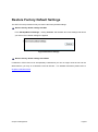
Restore Factory Default Settings
The SGT-LD-5-23 provides two ways to restore the factory default settings:
Restore factory default settings via Web
From “Backup/Restore Settings”, clicking “Restore” will eliminate all current settings and reboot
your device; then default settings are applied.
Figure 46 Restore Settings
Restore factory default settings via RS-232
If software in SGT-LD-5-23 has unexpectedly crashed and you can no longer reset the unit via the
Web interface, you may do a hardware reset via RS-232.
For detailed instructions please refer to
Chapter 2 RS-232 section.
Chapter 5 Management
Page 61
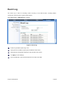
Event Log
The Event log is used for recording events occurring in the SGT-LD-5-23, including station
connections, disconnections, system reboot and etc.
Open “Event Log” in “Management” as below.
Figure 47 Event Log
Enable Log: Enable System log or not;
Syslog Server IP Address: Specify the IP address of the server;
Syslog Server Port Number: Specify the port number of the server;
Hit “Apply” to save settings;
Event Log Window: Lists all events that have occurred in this field.
Chapter 5 Management
Page 62
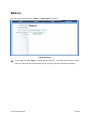
Reboot
You can reboot your device from “Reboot” in “Management” as below:
Figure 48 Reboot
Check “Yes” and click “Apply” to reboot the SGT-LD-5-23.
This takes a few minutes, during
which the device will send out a buzzing sound, informing you that the system is rebooting.
Chapter 5 Management
Page 63
Chapter 6 Troubleshooting
This chapter provides troubleshooting procedures for basic problems with the SGT-LD-5-23.
For
warranty assistance, please contact your service provider or distributor for the process.
Q 1. What if my SGT-LD-5-23 fails to connect to the remote one?
Ethernet Link: Check the availability of power to the bridge by observing the LED status on
the power injector or on top of the RJ-45 Jack of the unit.
-
Green: The SGT-LD-5-23 is connecting to the backhaul network.
-
Off: The SGT-LD-5-23 disconnects from the wired network; check if the power cord and
Ethernet cables to the network and bridge are correctly connected.
Basic Configurations: Mismatched basic settings among bridges are the most common
cause of connectivity failure.
If the bridge does not associate with a remote bridge, check
that options in each device are identical.
Security Settings: Remote bridges attempting to authenticate to your bridge must support
the same security options configured in your bridge, such as WEP and WPA (2)-PSK.
If
your bridge fails to associate with others, check that the security settings are the same as
your bridge settings.
Antenna Alignment: If the methods above are all checked to be correct, you can observe
and verify antenna alignment with RSSI value.
Q 2. What if I would like to reset the unit to default settings?
You may restore factory default settings in “Backup/Restore Settings” from “Management”.
Q 3. What if I would like to backup and restore my configuration settings?
You may do the backup by generating a configuration file or retrieve the settings you have backed
up previously in “Backup/Restore Settings” from “Management”.
Q 4. What if I cannot open the Web-based management interface?
Please check the followings:
Check if the power supply is OK; Try to power on the unit again.
Chapter 6 Troubleshooting
Page 64
Check if the IP address of PC is correct (in the same network segment as the unit);
Log into the unit via other browsers such as Firefox.
Hardware reset the unit.
Q 5. What if the signal quality is poor or not so good?
Check if there is obstacle between units.
Check the antenna height.
An obstacle may lead to a poor signal.
Placing the unit in a high position can help to get better
communication for long distance transmission.
Check the polarization direction of antenna.
Keep the polarization direction of antennas for
two associating units the same; if not (one is horizontal, another is vertical), the signal quality
will reduce dramatically.
Check the antenna angle.
antenna.
Align the antenna to the remote one if using a directional
A large angle shift may lead to a poor signal.
Check the feeder length.
Too long a feeder may increase the signal loss and affect the
unit‟s performance.
Chapter 6 Troubleshooting
Page 65
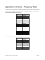
Appendix A. Channel – Frequency Table
The SGT-LD-5-23 can be operated in four different band widths, which are 5MHz, 10MHz, 20MHz and
40MHz. The following tables illustrate the channel with corresponding frequency in each bandwidth.
Table 4 Channels in 5MHz Centre Frequency
Channel
Frequency
149
5.745 GHz
150
5.750 GHz
151
5.755 GHz
152
5.760 GHz
153
5.765 GHz
154
5.770 GHz
155
5.775 GHz
156
5.780 GHz
157
5.785 GHz
158
5.790 GHz
159
5.795 GHz
160
5.800 GHz
161
5.805 GHz
162
5.810 GHz
163
5.815 GHz
164
5.820 GHz
165
5.825 GHz
Table 5 Channels in 10MHz Centre Frequency
Channel
Frequency
149
5.745 GHz
151
5.755 GHz
153
5.765 GHz
155
5.775 GHz
157
5.785 GHz
159
5.795 GHz
161
5.805 GHz
163
5.815 GHz
165
5.825 GHz
Appendix A. Channel – Frequency Table
Page 66
Table 6 Channels in 20MHz Centre Frequency
Channel
Frequency
149
5.745 GHz
153
5.765 GHz
157
5.785 GHz
161
5.805 GHz
165
5.825 GHz
Table 7 Channels in 40MHz Centre Frequency
Channel
Frequency
149
5.745GHz
157
5.785GHz
165
5.825GHz
The availability of some specific channels and/or operational frequency bands are country
dependent and are firmware programmed at the factory to match the intended destination. The
firmware setting is not accessible by the end user.
Appendix A. Channel – Frequency Table
Page 67
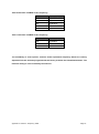
Appendix B. Channel – Country List Table
The SGT-LD-5-23 support country selection, there are different channel when select different country.
The following tables list the channel with country code in each bandwidth.
Table 8 Country of FCC
Country
Mode
Channel list
40Mhz
11bg
6
(1-11)
20Mhz
10Mhz
5Mhz
1/2/3/4/5/6/7/8/9/ 1/2/3/4/5/6/7/8/9/10 1/2/3/4/5/6/7/8/9/
10/11
/11
10/11
149/151/153/155/
149/150/151/152/
157/159/161/163
153/154/155/156/
165
157/158/159/160/
United States
11a
149/157/165 149/153/157/
(5725~5850)
161/165
161/162/163/164/
165
Appendix B. Channel – Country List Table
Page 68
Table 9 Country of European Union
Country
Mode
Channel list
40Mhz
Belgium
11bg (1-13)
Bulgaria
*Ukraine
Croatia
Excluded
Cyprus
CH12-CH13
6
20Mhz
10Mhz
5Mhz
1/2/3/4/5/6/78
1/2/3/4/5/6/7/8
1/2/3/4/5/6/7/8
/9/10/11/12/13
9/10/11/12/13
9/10/11/12/13
Czech
Republic
Estonia
Finland
F.Y.R.O.Mac
edonia
France
Germany
Greece
Hungary
Iceland
Italy
11a
100/108/116 100/104/108/112 100/102/104/106/
100/101/102/103/
(5470~5725)
140
104/105/106107/
116/136/140
108/110/112/114/
Excluded
116/118/134/136/1 108/109/110/111/
CH120~CH131
38/140
112/113/114/115/
Meteorology
116/117/118/119/
Radars
133/134/135/136/
Latvia
Lithuania
137/138/139/140/
141
Luxembourg
Malta
Netherlands
Poland
Portugal
Romania
Slovakia
Slovenia
Spain
Sweden
Turkey
South Africa
Nigeria
Russia
*Ukraine
Austria
Appendix B. Channel – Country List Table
Page 69
Table 10 Other Countries
Country
Mode
Channel list
40Mhz
11bg
6
20Mhz
10Mhz
5Mhz
1/2/3/4/5/6/7/8/9/ 1/2/3/4/5/6/7/8/9/10 1/2/3/4/5/6/7/8
10/11/12/13
/11/12/13
9/10/11/12/13
11a
100/108/116/ 100/104/108/112/ 99/101/103/105
99/100/101/102
(5470~5725)
140
/107/109/111/113
/103/104/105/106
Excluded
/115/117/119/133
/107/108/109/110
CH120~CH131
/135/137/139/141
/111/112/113/114
116/136/140
Meteorology
/115/116/117/118
Radars
/119/133/135/136
/137/138/139/140
/141
*Ireland
Liechtenstein
Norway
Switzerland
Denmark
(5725~5875)
151/167
Excluded
147/151/155/167/ 146/148/150/152
146/147/148/149/
171
/154/156/158/164
150/151/152/153/
/166/168/170/172
154/155/156/157/
/174
158/164/165/166/
5795~5815
167/168/169/170/
171/172/173/174
*Ireland
151/167
Excluded
5795~5805
147/151/155/163/ 146/148/150
146/147/148/149/
167/171
/152/154/156/158
150/151/152/153/
/162/164/166/168
154/155/156/157/
/170/172/174
158/162/163/164/
165/166/167/168/
169/170/171/172/
173/174
Appendix B. Channel – Country List Table
Page 70
11bg
6
(1-13)
1/2/3/4/5/6/7/8/9/ 1/2/3/4/5/6/7/8
1/2/3/4/5/6/7/8
10/11/12/13
9/10/11/12/13
9/10/11/12/13
11a
100/108/
100/104/108/112/ 99/101/103/105
99/100/101/102
(5470~5725)
116/140
116/136/140
/103/104/105/106
/107/109/111/113
Excluded
/115/117/119/133/ /107/108/109/110
CH120~CH131
135/137/139/141
/111/112/113/114
Meteorology
/115/116/117/118
Radars
/119/133/135/136
/137/138/139/140
UK
/141
(5725~5850)
151/167
147/151/155/167 146/148/150/152
146/147/148/149/
Excluded
/154/156/158/164
150/151/152/153/
5795~5815
/166/168
154/155/156/157/
158/162/163/164/
165166/167/168/
169
Appendix B. Channel – Country List Table
Page 71
Appendix C. ASCII
WEP can be configured with a 64-bit or 128-bit Shared Key (hexadecimal number or ACSII). As
defined, hexadecimal number is represented by 0-9, A-F or a-f; ACSII is represented by 0-9, A-F, a-f or
punctuation. Each one consists of two-digit hexadecimal.
Table 11 ACSII
ASCII
Hex
ASCII
Hex
ASCII
Hex
ASCII
Hex
Character
Equivalent
Character
Equivalent
Character
Equivalent
Character
Equivalent
!
21
9
39
Q
51
i
69
"
22
:
3A
R
52
j
6A
#
23
;
3B
S
53
k
6B
$
24
<
3C
T
54
l
6C
%
25
=
3D
U
55
m
6D
&
26
>
3E
V
56
n
6E
„
27
?
3F
W
57
o
6F
(
28
@
40
X
58
p
70
)
29
A
41
Y
59
q
71
*
2A
B
42
Z
5A
r
72
+
2B
C
43
[
5B
s
73
,
2C
D
44
\
5C
t
74
-
2D
E
45
]
5D
u
75
.
2E
F
46
^
5E
v
76
/
2F
G
47
_
5F
w
77
0
30
H
48
`
60
x
78
1
31
I
49
a
61
y
79
2
32
J
4A
b
62
z
7A
3
33
K
4B
c
63
{
7B
4
34
L
4C
d
64
|
7C
5
35
M
4D
e
65
}
7D
6
36
N
4E
f
66
~
7E
7
37
O
4F
g
67
8
38
P
50
h
68
Appendix C. ASCII
Page 72
Appendix D. SSH Settings
Table 12 SSH Settings
get
set
√
√
del
Keyword
Descriptions
time
--time setting
√
-now
--current system time
√
√
-zone
--time zone
√
√
-daylight saving
-- daylight saving
√
√
-server
--time server setting
√
√
-name
√
√
-port
√
√
√
√
√
or IP address)
--time server port
system
√
√
--time server (domain name
√
--system setting
-version
--system firmware version
-devicename
--system name
-macaddr
--system MAC address
-country
--country/region
-restoreFactory
√
--restore factory default
Default
√
√
-iptype
--system dhcp client
√
√
-ipaddr
--system IP address
√
√
-netmask
--system network mask
√
√
-gateway
--system gateway
√
√
-dns
--system dns
√
√
-primary
√
√
-secondary
√
√
-stp
√
√
-ethrate
--ethernet data rate
-ethstats
--ethernet statistics
√
--primary
system
server
--secondary system DNS
server
--enable
spanning
√
√
√
√
√
√
√
-ipaddr
--radius IP address
√
√
-port
--radius port number
get
set
√
√
√
√
radius
--radius setting
--authentication
-auth
radius
setting
-primary
--primary
Keyword
Appendix D. SSH Settings
tree
protocol
√
del
DNS
Descriptions
-secret
-secondary
--radius secret string
--secondary
Page 73
√
√
-ipaddr
--radius IP address
√
√
-port
--radius port number
√
√
-secret
--radius secret string
√
√
√
√
-reauthtime
√
√
-keyupdate
√
√
-mode
√
√
-interval
√
√
√
√
√
√
-ipaddr
--radius IP address
√
√
-port
--radius port number
√
√
-secret
--radius secret string
√
√
√
√
-ipaddr
--radius IP address
√
√
-port
--radius port number
√
√
-secret
--radius secret string
√
√
ssh
√
√
snmp
√
√
√
√
√
√
√
√
√
√
√
√
-client
--enable syslog client
√
√
-ipaddr
--syslog server IP address
√
√
-port
--syslog server port number
√
√
√
√
get
set
√
-wpa
--wireless WPA setting
--wireless
re-auth
period(in seconds)
--enable
wireless
WPA
global update condition
-account
--wireless WPA global key
update condition
--wireless WPA global key
update interval
--account radius setting
-primary
--primary
-secondary
--secondary
--enable
remote
SSH
access
--SNMP setting
-server
--enable SNMP agent
--SNMP
-trap server
-read
community
-write
community
log
TrapServer
IP
address
--SNMP ReadCommunity
--SNMP WriteCommunity
--syslog setting
wlan
--wireless setting
-wirelessmode
del
WPA
Keyword
--wireless mode
Descriptions
--wireless channel(depends
√
√
-channel
on country and wireless
mode)
√
√
Appendix D. SSH Settings
-txrate
--wireless transmission data
rate
Page 74
√
√
-bandwidth
--wireless bandwidth
√
√
-cpe mode
--use multicli or lan-to-lan
√
√
-cpedownflowwi
--wireless down flow width
dth
for CPE mode
√
√
-OutputPower
--wireless transmit power
√
√
-VQoS/TDM
--enable TDM mode or not
√
√
-tdm timeslice
--station‟s timeslice value
√
√
-fragmentationt
--wireless
hreshold
threshold(even only)
√
√
-rtsthreshold
√
√
-beaconinterval
√
√
fragmentation
--wireless
RTS/CTS
threshold
--wireless beacon period in
TU (1024us)
-operating
--wireless operation mode
mode
--wireless
√
√
√
-remotebs
remote
AP(s)(depends
on
operation mode)
√
√
√
√
√
√
√
√
√
√
√
√
√
--remote AP address for pxp
-pxp
mode
-wirelessis
olate
--pxp wirelessisolate
st
-1
--1
remote AP for pxp
mode
-macaddre
-- remote AP mac address
ss
for pxp mode
-bandwidth
--down flow width for pxp
mode
--remote AP status or active
√
-status
√
-ipaddr
--remote AP ipaddr
√
-rssi
--remote AP rssi
for pxp mode
nd
√
√
√
√
√
√
get
set
del
√
√
-2
--2
remote AP for pxp
mode
-macaddre
--remote AP mac address
ss
for pxp mode
Keyword
Descriptions
-bandwidth
--down flow width for pxp
mode
--remote AP status or active
√
-status
√
-ipaddr
--remote AP ipaddr
√
-rssi
--remote AP rssi
-3
--3
√
√
√
Appendix D. SSH Settings
for pxp mode
rd
remote AP for pxp
Page 75
mode
√
√
√
√
√
-macaddre
--remote AP mac address
ss
for pxp mode
-bandwidth
--down flow width for pxp
mode
--remote AP status or active
√
-status
√
-ipaddr
--remote AP ipaddr
√
-rssi
--remote AP rssi
for pxp mode
th
√
√
√
√
√
√
√
√
-4
--4
remote AP for pxp
mode
-macaddre
--remote AP mac address
ss
for pxp mode
-bandwidth
--down flow width for pxp
mode
--remote AP status or active
√
-status
√
-ipaddr
--remote AP ipaddr
-rssi
--remote AP rssi
√
√
√
√
√
√
√
√
√
√
-acl
--wireless access control
--enable
-mode
√
-all
√
-(null)
--(delete only)all local ACL
address
--edit local ACL address
--list of associated wireless
-association
√
clients
-wlanstats
--wlan statistics
-key
--wireless wep key setting
√
√
√
√
√
√
√
get
set
del
√
√
√
-2
--wireless wep key 2
√
√
√
-3
--wireless wep key 3
√
√
√
-4
--wireless wep key 4
√
√
√
√
√
√
-type
--wireless wep key type
-1
--wireless wep key 1
Keyword
Descriptions
-spaceinmeter
√
access
--display trusted CPEs
√
√
wireless
control(ACL)
-list
√
for pxp mode
-remotebssid
-remotessid
--wireless space in meter
--wireless remote bssid in
cpe mode
--wireless remote ssid in
cpe mode
√
-network-status
--wireless network status
√
-bsscanlist
--bs list
√
-signal level
--signal level(dBm)
Appendix D. SSH Settings
Page 76
√
-remoterssi
--remote bs and rssi
√
√
-wmm
--wmm settngs
√
√
-super_audio
--Fast_Frame settings
√
√
-super_video
--super burst settings
√
√
-super_picture
--compression settings
√
√
-bs
--<null>
√
√
-ssid
√
√
-hiddenssid
√
√
√
√
√
√
-encryption
--bs data encryption
√
√
-default
--bs wep default key index
√
--network
name
of
this
bs(1-32 chars)
--bs
ssid
broadcast
suppress
-wirelessis
--bs isolate communication
olate
between clients
-authentica
tion
--bs authentication type
--bs pre-shared key(PSK)
√
√
√
√
√
-autowdsenable
--auto wds settings
√
√
-wdsgroupid
--wds group id name
-psk
for
WPA-PSK
WPA2-PSK
password
--system password
reboot
--reboot system
exit
--logout from CLI
quit
--quit CLI
Appendix D. SSH Settings
Page 77
or
Appendix E. GPL Declamation
PUBLIC SOFTWARE DECLAMATION
In the software we delivered, there are may contain some public software, if it is, please read
below carefully:
1. Definition
“Public Software”, when applicable, shall mean that portion of the Licensed Software, in source code
form, set forth in the below Table, and provided under the terms set forth in the Section 5, the indicated
website, the complete license terms can be found .
“Public Software” shall mean each of:
(a) any computer code that contains, or is derived in any manner (in whole or in part) from, any
computer code that is distributed as open source software (e.g. Linux) or similar licensing or
distribution models; and
(b) any software that requires as a condition of use, modification and/or distribution of such software
that such software or other software incorporated into, derived from or distributed with such software (i)
be disclosed or distributed in source code form, (ii) be licensed for the purpose of making derivative
works, or (iii) be redistributable at no charge.
Public Software includes, without limitation, software licensed or distributed under any of the following
licenses or distribution models, or licenses or distribution models similar to any of the following: (1)
GNU‟s General Public License (GPL) or Lesser/Library GPL (LGPL); (2) the Artistic License (e.g.,
PERL); (3) the Mozilla Public License; (4) the Netscape Public License; (5) the Sun Community
Source License (SCSL); (6) the Sun Industry Source License (SISL); and (7) the Apache Software
license.
2. Limited Use
Any Public Software provided under the agreement shall be subject to the licenses, terms and
conditions of its model.
Licensee hereby agrees to comply with the terms and conditions applicable
to any such Public Software, as set forth in its presentation on website.
Appendix E. GPL Declamation
Page 78
3. Limited Liability
The supplier hereby express that the supplier shall have no liability for any costs, loss or damages
resulting from Licensee‟s breach of the terms and conditions applicable to use, conversion or
combination of the licensed software with or into Public Software.
4. NO WARRANTY.
This program or licensed software is distributed in the hope that it will be useful, but WITHOUT ANY
WARRANTY. THE PROGRAM "AS IS" WITHOUT WARRANTY OF ANY KIND, EITHER EXPRESSED
OR IMPLIED, INCLUDING, BUT NOT LIMITED
TO, THE IMPLIED WARRANTIES OF
MERCHANTABILITY AND FITNESS FOR A PARTICULAR PURPOSE. THE ENTIRE RISK AS TO
THE QUALITY AND PERFORMANCE OF THE PROGRAM IS WITH LICENSEE.
5. Public Software Name and Description
Table 13 Public Software Name and Description
Program
Copy Right Description
Name
Redboot
Copyright
(C)
Origin
Licenses or Distribution
License
Terms
Sour Code
Models or its special
Website
license terms
Reference
eCos License
http://sources.re
1998,
ftp://ftp.ge
1999, 2000, 2001, 2002,
s.redhat.c
dhat.com/ecos/e
2003 Red Hat, Inc.
om/private
cos-license/
/gnupro-xs
cale-03042
2/redboot-i
ntel-xscale
-030630.tar
.Z
Busybox
http://www
GNU GENERAL PUBLIC
http://www.gnu.o
.busybox.
LICENSE Version 2
rg/licenses/old-li
net/downl
censes/gpl-2.0.ht
oads/busy
ml
box-1.01.ta
r.bz2
brctl
Copyright
(C)
2000
Lennert Buytenhek
http://nchc
GNU GENERAL PUBLIC
http://www.gnu.o
.dl.sourcef
LICENSE Version 2
rg/licenses/old-li
orge.net/s
Appendix E. GPL Declamation
censes/gpl-2.0.ht
Page 79
ourceforg
ml
e/bridge/br
idge-utils1.0.6.tar.gz
dropbear
Copyright
(c)
http://matt.
GNU GENERAL PUBLIC
http://www.gnu.o
2002-2006
Matt
ucc.asn.au
LICENSE Version 2
rg/licenses/old-li
Johnston
/dropbear/
censes/gpl-2.0.ht
Portions copyright (c)
dropbear-
ml
2004
0.51.tar.bz
Mihnea
Stoenescu
hostapd
2
Copyright
2002-2006,
(c)
http://host
GNU GENERAL PUBLIC
http://www.gnu.o
Jouni
ap.epitest.
LICENSE Version 2
rg/licenses/old-li
Malinen
fi/releases/
censes/gpl-2.0.ht
<[email protected]>
hostapd-0.
ml
and
4.8.tar.gz
contributors
wpa_sup
Copyright
plicant
2003-2005,
(c)
http://host
GNU GENERAL PUBLIC
http://www.gnu.o
Jouni
ap.epitest.
LICENSE Version 2
rg/licenses/old-li
Malinen
fi/releases/
censes/gpl-2.0.ht
<[email protected]>
wpa_suppl
ml
and
icant-0.4.7.
contributors
tar.gz
mtdutil
ftp://ftp.uk.
GNU GENERAL PUBLIC
http://www.gnu.o
linux.org/p
LICENSE Version 2
rg/licenses/old-li
ub/people/
censes/gpl-2.0.ht
dwmw2/mt
ml
d/cvs/mtd/
util/
ntpclient
Copyright 1997, 1999,
http://dooli
GNU GENERAL PUBLIC
http://www.gnu.o
2000,
ttle.icarus.
LICENSE Version 2
rg/licenses/old-li
2003
Larry
Doolittle
com/ntpcli
censes/gpl-2.0.ht
ent/ntpclie
ml
nt_2003_1
94.tar.gz
procps
Author: Albert Cahalan,
http://proc
GNU GENERAL PUBLIC
http://www.gnu.o
Michael
ps.sourcef
LICENSE Version 2
rg/licenses/old-li
orge.net/p
GNU
censes/gpl-2.0.ht
rocps-3.2.
GENERAL
7.tar.gz
LICENSE Version 2
K.
Johnson,
Jim Warner, etc.
LIBRARY
PUBLIC
ml
http://www.gnu.o
rg/licenses/old-li
censes/library.ht
ml
vsftpd
Author: Chris Evans
Appendix E. GPL Declamation
ftp://vsftpd
GNU GENERAL PUBLIC
http://www.gnu.o
.beasts.or
LICENSE Version 2
rg/licenses/old-li
Page 80
g/users/ce
censes/gpl-2.0.ht
vans/vsftp
ml
d-1.1.2.tar.
gz
linux
ftp://ftp.ker
GNU GENERAL PUBLIC
http://www.gnu.o
nel.org/pu
LICENSE Version 2
rg/licenses/old-li
b/linux/ker
censes/gpl-2.0.ht
nel/v2.6/lin
ml
ux-2.6.20.3
.tar.bz2
Appendix E. GPL Declamation
Page 81