1
Keyboard Wedge/
Decoded Out Wand
Technical Manual
STATEMENT OF AGENCY COMPLIANCE
FCC ID: EIF58QST2380
This device complies with part 15 of the FCC Rules. Operation is subject to the
following two conditions: (1) this device may not cause harmful interference,
and (2) this device must accept any interference received, including
interference that may cause undesired operation.
FCC Class B Compliance Statement
This equipment has been tested and found to comply with the limits for a Class B
digital device pursuant to part 15 of the FCC Rules. These limits are designed to
provide reasonable protection against harmful interference in a residential
installation. This equipment generates, uses, and can radiate radio frequency
energy and, if not installed and used in accordance with the instructions, may
cause harmful interference to radio communications. However, there is no
guarantee that interference will not occur in a particular installation. If this
equipment does cause harmful interference to radio or television reception,
which can be determined by turning the equipment off and on, the user is
encouraged to try to correct the interference by one or more of the following
measures:
• Reorient or relocate the receiving antenna.
• Increase the separation between the equipment and receiver.
• Connect the equipment into an outlet on a circuit different from that
to which the receiver is connected.
• Consult the dealer or an experienced radio or television technician for help.
Caution: Any changes or modifications made to this device that are not
expressly approved by Welch Allyn, Inc. may void the user’s authority to
operate the equipment.
Note: To maintain compliance with FCC Rules and Regulations, cables
connected to this device must be shielded cables, in which the cable shield
wire(s) have been grounded (tied) to the connector shell.
Canadian Notice
This equipment does not exceed the Class B limits for radio noise emissions as
described in the Radio Interference Regulations of the Canadian Department of
Communications.
Le present appareil numerique n’emet pas de bruits radioelectriques depassant
les limites applicables aux appareils numeriques de la classe B prescrites dans
le Reglement sur le brouillage radioelectrique edicte par le ministere des
Communications du Canada.
The CE mark on the product indicates that the system has been tested to and
conforms with the provisions noted within the 89/336/EEC Electromagnetic
Compatibility Directive and the 73/23/EEC Low Voltage Directive.
European Contact:
European Regulatory Manager
Welch Allyn Ltd.
28 Sandyford Office Park
Foxrock, Dublin 18
Ireland
or
Welch Allyn Ltd.
The Lodge, Tanners Lane
Warrington, Cheshire WA2 7NA
England
Welch Allyn shall not be liable for use of our product with equipment
(i.e., power supplies, personal computers, etc.) that is not CE marked and
does not comply with the Low Voltage Directive.
Disclaimer
Welch Allyn reserves the right to make changes in specifications and
other information contained in this document without prior notice, and the
reader should in all cases consult Welch Allyn to determine whether any
such changes have been made. The information in this publication does
not represent a commitment on the part of Welch Allyn.
Welch Allyn shall not be liable for technical or editorial errors or
omissions contained herein; nor for incidental or consequential
damages resulting from the furnishing, performance, or use of this
material.
This document contains proprietary information which is protected by
copyright. All rights are reserved. No part of this document may be
photocopied, reproduced, or translated into another language without
the prior written consent of Welch Allyn, Incorporated.
1999 Welch Allyn, Inc. All rights reserved.
Data Collection Web Addresss: http://dcd.welchallyn.com
Limited Warranty
Welch Allyn, Inc., hereby warrants its standard Decoded Output Scanner to
be functional and free from manufacturing defects at the time of delivery.
Welch Allyn, Inc. further warrants that it will replace or repair, at its
option, any unit that fails to perform according to Welch Allyn’s published
specifications during a period of five (5) years from the time of shipment
by Welch Allyn, Inc. to the user or the time it is purchased from any of
Welch Allyn Inc.’s Authorized Distributors. Any attempt on the part of the
user to disassemble or service the wand, except for tip replacement, shall
void the warranty.
This warranty does not apply to products which have been damaged by
improper handling, shipping or misuse. The warranty does not apply if, in
the sole opinion of Welch Allyn, Inc., the unit has been damaged by
accident, misuse, neglect, improper shipping or handling. Since the unit is
sensitive to static discharges and electricity, the responsibility to protect it
from static damage is solely that of the user. The warranty is valid only if
the wand has not been tampered with, or serviced by any party
unauthorized by Welch Allyn, Inc. as a repair facility.
THE WARRANTIES SET FORTH HEREIN ARE IN LIEU OF ANY AND ALL
OTHER WARRANTIES EXPRESSED OR IMPLIED INCLUDING THE
WARRANTIES OF MERCHANTABILITY AND FITNESS FOR A
PARTICULAR PURPOSE. THE BUYER ACKNOWLEDGES THAT NO
OTHER REPRESENTATIONS WERE MADE OR RELIED UPON WITH
RESPECT TO THE QUALITY AND FUNCTION OF THE SCANNER HEREIN
SOLD.
In no event shall Welch Allyn, Inc. or its resellers be liable for any loss,
inconvenience or damage whether direct, incidental, consequential or
otherwise, and whether caused by negligence or other fault resulting from
the breach of any express warranty except as set forth herein. Some states
do not allow the exclusion or limitation of incidental or consequential
damages, so the above limitations or exclusions may not apply to you.
This warranty gives you specific legal rights, and you may also have other
rights which vary from state to state or country to country.
Limited Warranty
Limited Warranty
TABLE OF CONTENTS
Statement of Agency Compliance
Limited Warranty
Chapter 1
Introduction to the SCANTEAM 2380 Scanner
Section
Page
1.1
1.2
1.3
1.4
Chapter 2
Introduction . . . . . . . . . . . . . . . . . . . . . . . . . . . . . . . .
Hardware Description . . . . . . . . . . . . . . . . . . . . . . .
Software Description . . . . . . . . . . . . . . . . . . . . . . . .
Wand Models . . . . . . . . . . . . . . . . . . . . . . . . . . . . . .
Operational Description
Section
2.1
2.2
2.3
2.4
2.5
Chapter 3
Page
Chapter Objectives . . . . . . . . . . . . . . . . . . . . . . . . .
Main Elements of the 2380 System . . . . . . . . . . .
Scanner Identification Label . . . . . . . . . . . . . . . . .
Operating Theory . . . . . . . . . . . . . . . . . . . . . . . . . .
Factors Affecting Scanner Performance . . . . . . .
2.5.1
Scanner Illumination Source . . . . . . . .
2.5.2
Scanning Aperture . . . . . . . . . . . . . . . . .
2.5.3
Depth of Field . . . . . . . . . . . . . . . . . . . . .
2.5.4
Scanning Velocity . . . . . . . . . . . . . . . . . .
2.5.5
High/Low Density Bar Codes . . . . . . . .
2.5.6
Print Contrast . . . . . . . . . . . . . . . . . . . . .
2–1
2–1
2–2
2–2
2–2
2–2
2–3
2–4
2–4
2–4
2–5
Setup and Installation
Section
3.1
3.2
3.3
3.4
1–1
1–1
1–3
1–4
Page
Chapter Description . . . . . . . . . . . . . . . . . . . . . . . .
Preparation . . . . . . . . . . . . . . . . . . . . . . . . . . . . . . . .
Setup and Installation . . . . . . . . . . . . . . . . . . . . . . .
Scanner Checks . . . . . . . . . . . . . . . . . . . . . . . . . . .
Table of Contents
3–1
3–1
3–1
3–3
i
Chapter 4
Programming the Scanner
Section
4.1
4.2
4.3
4.4
4.5
4.6
4.7
4.8
4.9
4.10
4.11
Chapter 5
Page
Introduction . . . . . . . . . . . . . . . . . . . . . . . . . . . . . . . .
The Programming Menu . . . . . . . . . . . . . . . . . . . .
4.2.1
Programming Menu Pages . . . . . . . . . .
4.2.2
Facing Page . . . . . . . . . . . . . . . . . . . . . .
4.2.3
Bar Code Chart . . . . . . . . . . . . . . . . . . .
Direct Connect Terminal Selection Menu Page .
Terminal Selection Menu Page . . . . . . . . . . . . . . .
Output Parameters & Format Menu Page . . . . .
COMM 1 Menu Page . . . . . . . . . . . . . . . . . . . . . . .
Scancode Selection Menu Page . . . . . . . . . . . . . .
Symbology Selection Menu Page . . . . . . . . . . . . .
Message Format . . . . . . . . . . . . . . . . . . . . . . . . . . .
Configuration Example . . . . . . . . . . . . . . . . . . . . . .
Keyboard Layouts and Delimiters . . . . . . . . . . . . .
Maintenance and Troubleshooting
Section
5.1
5.2
5.3
5.4
5.5
ii
4–1
4–1
4–1
4–4
4–4
4–6
4–6
4–6
4–12
4–13
4–14
4–15
4–16
4–18
Page
Scanner Maintenance and Service . . . . . . . . . . .
Cleaning . . . . . . . . . . . . . . . . . . . . . . . . . . . . . . . . . .
Inspection . . . . . . . . . . . . . . . . . . . . . . . . . . . . . . . . .
Troubleshooting . . . . . . . . . . . . . . . . . . . . . . . . . . . .
Obtaining Factory Service in the U.S. . . . . . . . . .
Obtaining Factory Service in Europe . . . . . . . . . .
Obtaining Factory Service in Asia . . . . . . . . . . . .
Technical Support . . . . . . . . . . . . . . . . . . . . . . . . . .
Table of Contents
5–1
5–1
5–2
5–2
5–4
5–4
5–4
5–5
Appendices
A
Technical Specifications
Section
Page
A.1
A.2
A.3
A.4
A.5
A.6
B
A–1
A–1
A–2
A–4
A–4
A–5
Scanner Performance . . . . . . . . . . . . . . . . . . . . . . . . . . .
Optical Specifications . . . . . . . . . . . . . . . . . . . . . . . . . . .
Electrical Specifications . . . . . . . . . . . . . . . . . . . . . . . . .
Environmental Specifications . . . . . . . . . . . . . . . . . . . . .
Mechanical Specifications . . . . . . . . . . . . . . . . . . . . . . .
Bar Code Symbol Specifications . . . . . . . . . . . . . . . . . .
Keyboard Function Relationships
B.1
Keyboard Function Relationships . . . . . . . .
B–1
Index
List of Illustrations
Figure
1.1
3.1
4.1
4.2
4.3
Page
Keyboard Wedge Connection . . . . . . . . . . . . . . . . . . .
“Y” Interface Cable Connections . . . . . . . . . . . . . . . .
Example of Programming Menu Page . . . . . . . . . . .
Bar Code Chart . . . . . . . . . . . . . . . . . . . . . . . . . . . . . . .
NCR 7052/32 & 56 Key Terminal . . . . . . . . . . . . . . . .
Table of Contents
1–2
3–2
4–2
4–4
4–18
iii
Preface
SCANTEAM 2380 Bar Code Wand Scanners are used in both retail and
commercial environments. The retail environment includes point–of–sale
uses, while the commercial environments include industrial type
applications (e.g., time and attendance information gathering).
This technical manual is an extension of the SCANTEAM 2380
Programming Menu. The Programming Menu contains information and
bar codes that you will use to set up your system to meet your needs. This
manual provides you with additional, in–depth information about the
options in the Programming Menu.
Chapter 1 provides a description of the 2380 scanner software and
hardware.
Chapter 2 is an in–depth description of the operating system, explaining
how the scanner works, and how it reads/decodes a bar code symbol.
Scanner identification and scanning techniques are discussed.
Chapter 3 explains how to set up and install your scanner. Instructions to
confirm scanner operation and to check bar code labels is provided.
Chapter 4 explains how to program your scanner to meet your specific
needs. Refer to Chapter 4 for detailed information when you are using the
2380 Programming Menu.
Chapter 5 explains how to maintain (clean and inspect), troubleshoot and
obtain service and technical assistance for your 2380 scanner.
Appendix A provides information about scanner performance, optical,
electrical, environmental, mechanical, and bar code label specifications.
iv
Table of Contents
INTRODUCTION TO THE
SCANTEAM 2380 SCANNER
1
1.1 Introduction
The SCANTEAM 2380 Decoder Output Scanner Keyboard Wedge is a
convenient and cost effective way of adding bar code data entry capability
to the IBM (and IBM compatible) PC/XT/AT personal computers and IBM
PS/2 Models 30, 50, 60 and 80.
Additional interfaces are continually being developed; check with Welch
Allyn or an authorized representative for availability.
As described on page 1–4, the SCANTEAM 2380 is available in the
following models: 2380/J and 2380/K with visible red illumination. All
models of the 2380 are available with stainless steel scanner housings. The
contents of this manual applies to these devices except where
differentiated.
The SCANTEAM 2380 is designed to read and decode any of nine (9)
popular bar code symbologies and output the bar code data to the keyboard
port in the same format the keyboard does.
1.2 Hardware Description
The SCANTEAM 2380 system consists of the wand body and a 6’ (1.8m)
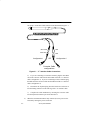
coil (extended) interface cord. When connected as shown in Figure 1.1, the
2380 keyboard “wedge” device provides a transparent interface between
the keyboard and the keyboard input port of the host device.
Operation of the SCANTEAM 2380 with a particular computer is
accomplished by installing the proper “Y” interface cable and
programming the proper keyboard interface routine using the TERMINAL
SELECTION sheet of the programming menu.
Introduction to the SCANTEAM 2380
1–1
Once installed, the 2380 simply passes keyboard activity onto the host.
Symbols decoded by the SCANTEAM 2380 are translated to
corresponding keyboard keycodes and then sent to the keyboard input port
of the terminal. Thus, the data appears as if it has been “keyed in” at the
keyboard.
Figure 1.1 SCANTEAM 2380 Keyboard Wedge Connection
Decoding capability is achieved through the use of an internal
microprocessor.
All SCANTEAM 2380 units are referred to as contact scanners since the
tip of the wand must be in or near contact with the bar code label in order
to read.
1–2
Introduction to the SCANTEAM 2380
1.3 Software Description
The standard SCANTEAM 2380 is configured for specific user
applications by scanning bar code symbols from the printed programming
menu which is supplied with the unit.
System software will support the keyboard model normally supplied with
the host device, and is capable of emulating keyboard “function keys.”
The SCANTEAM 2380 may be programmed to autodiscriminate among
the following bar code symbologies and their variations: CODABAR,
Code 3 of 9, UPC, EAN/JAN, Code 2 of 5, Interleaved 2 of 5, Code 93,
MSI, Code 128 and Code 11§.
In addition to the bar code symbology selections, certain input/output
parameters, message format and communications protocol are
programmable using the wand with the programming menu.
All programmable parameters are stored in non–volatile memory resident
in the wand where they are permanently retained in the event of power
interruption to the 2380 or the host device.
§
This feature is not supported in all wand models/software revisions.
Introduction to the SCANTEAM 2380
1–3
1.4 Wand Models
The SCANTEAM 2380 decoded output scanner keyboard wedge is
available in the following Welch Allyn industrial grade digital wand
scanner models:
SCANTEAM 2380/J and SCANTEAM 2380/K
The 2380/J and 2380/K are “SRD” scanners, meaning they have a visible
red LED illumination source. These units feature a durable body and a
replaceable tip. The 2380 has a Welch Allyn logo on the scanner housing.
Either of the models may be ordered with high, medium or low resolution
scanning optics so as to meet special requirements imposed by the label
substrate and printing method or environmental factors which affect bar
code label quality.
For additional assistance in selecting the SCANTEAM 2380 decoded
output scanner keyboard wedge best suited to your bar code application,
contact Welch Allyn or an authorized representative.
1–4
Introduction to the SCANTEAM 2380
OPERATIONAL DESCRIPTION
2
2.1 Chapter Objectives
This chapter describes:
•
Scanner identification key.
•
Overview of how the SCANTEAM 2380 works, including scanning
aperture, depth of field and scanning velocity.
•
Reading and decoding a bar code symbol. Description of print
contrast, high and low density bar code symbols.
•
Discussion of RS–232 interface and external power options.
2.2 Main Elements of the 2380 Bar Code System
The major operational elements of the SCANTEAM 2380 decoded output
scanner keyboard wedge include the scanner optics, the digitizing
electronics and the decoding circuitry.
The key components of the scanner optical system are the illumination
source (LED) and the illumination sensor (photodiode). Both the LED and
photodiode are positioned directly behind a specially designed lens in the
scanner body.
Cable connections are made directly to the board and exit the scanner body
through a flexible strain relief at the end of the wand handle. The integral
cable shield affords EMI and associated drain protection to output signals.
Operational Description
2–1
2.3 Scanner Identification Label
The scanner identification label is located on the scanner’s cable. The
identification corresponds to the configuration work sheet description.
(Welch Allyn p/n 16206714)
2.4 Operating Theory
The reading ability of the wand scanner is based on the detection of
reflected illumination from the bars and spaces which form a bar code
symbol.
During a typical scanning operation, the tip of the scanner is moved across
the bar code symbol. Illumination from the LED is focused on the bar
code symbol. This is absorbed by the dark colored bars and reflected by
the lighter background.
The reflected portion re–enters the scanner through the lens where it is
detected by the read sensor photodiode. The photodiode converts this into
a series of analog pulses which are proportional in width to the bars and
spaces in the symbol. These pulses are then digitized and sent to the
microprocessor where they are decoded into the characters represented by
the bar code symbol.
2.5 Factors Affecting Scanning Performance
The following factors influence reading performance and should be
considered when selecting a contact scanner for a particular bar code
application.
2.5.1
Scanner Illumination Source
Wand type scanners are equipped with a visible red (660nm) source.
2–2
Operational Description
Red illumination is compatible with most printing inks including most
thermal papers. Because it provides a visual indication to the operator that
the scanner is functioning, red illumination is considered to be more user
friendly. Visual feedback to the operator is an important consideration
when making a scanner selection.
2.5.2
Scanning Aperture
Scanning performance is affected by the size of the scanning aperture and
it is a significant factor to be considered when selecting a scanner. The
scanning aperture defines the effective size of the area of the bar code
symbol viewed by the scanner optics. It affects the relative ability of the
scanning device to “see” or resolve bars and ignore printing defects.
Large aperture systems typically cannot resolve high density bar code or
the small printing features (voids within bars or dark specs within the light
areas) that small aperture systems would. Thus, they are more compatible
with low density bar code and more tolerant of printing defects
characteristic of poorly printed labels.
Small aperture systems (high resolution) are better able to resolve which
makes them compatible with high density good quality symbol reading
requirements.
The SCANTEAM 2380 is available with circular apertures ranging from 6
to 8 mil.
Most scanning applications can be satisfied with a 6 mil (high resolution)
or a 8 mil (low resolution) aperture. When selecting an aperture, it is
recommended that the aperture dimension be no less than 0.7 times the “X”
(width of the narrowest bar code coding element) dimension to be read.
An aperture size that is slightly smaller than the narrowest bar code
element, 0.9 times “X,” provides optimum resolution of the bars and results
in the generation of a digital signal which accurately represents the bar
code. An 8 mil (0.2mm) aperture is often a good compromise when labels
produced by different printing and label generation methods must be read
with one scanner. In no case should the viewing aperture exceed 1.2 the
“X” dimension.
Operational Description
2–3
2.5.3
Depth of Field
Depth of field is the maximum perpendicular distance from the scanner tip
to the bar code symbol surface at which the scanner is capable of operating
effectively. In general, most of the SCANTEAM 2380 scanners have a
depth of field of 0.065 inches (1.65mm) with a symbol appropriate for the
scanner.
A chart showing the relationships between depth of field, scanning aperture
and bar code density appears on page A–1.
In normal use, the wand is seldom held perpendicular to the surface of the
bar code symbol. Rather, an operator tends to tilt the scanner. Useable
scan angle is a function of tip geometry and depth of field. If the depth of
field is too small, the scanner may fail to operate at extreme tilt angles
(>35°).
2.5.4
Scanning Velocity
The wand will operate at scan velocities from 2 to 50 inches/second (5 to
127cm per second) when the minimum bar/space size exceeds 7 mils
(0.18mm).
2.5.5
High Density vs Low Density Bar Code Symbols
Bar code density is a measure of the number of characters in a linear
measure of bar code. The standard of measure is normally given in terms
of the “X” dimension, the width of the narrowest bar code element. As bar
code density increases, the width of the narrowest bar code element
decreases. The scanning aperture should always be smaller than the
narrowest element to assure optimum resolution and the generation of a
digital signal which accurately represents the bar code.
2–4
Operational Description
2.5.6
Print Contrast
Print contrast is a measure of the relative difference in brightness between
the bars and spaces of a symbol and is specified as the Minimum
Reflectivity Difference (MRD). The MRD is the difference between the
lowest minimum space reflectance value and the highest maximum bar
reflectance value as measured across the entire symbol.
MRD = Max (Rb max) – Min (Rs min)
where:
Rs min = Minimum Space Reflectance
Rb max = Maximum Bar Reflectance
The scanner will operate with a MRD as low as 37.5% with the proper
aperture and appropriate symbol.
A complete description of bar code specifications for factors which affect
overall bar code quality are provided on page A–5.
Operational Description
2–5
2–6
Operational Description
SET–UP AND INSTALLATION
3
3.1 Chapter Description
This chapter describes:
•
Unpacking the SCANTEAM 2380
•
Connecting the SCANTEAM 2380
•
Confirming scanner operation
•
Checking bar code labels
3.2 Preparation
The SCANTEAM 2380 is shipped ready for use. Upon receipt, open the
carton(s) and check the contents. Check the part numbers and confirm that
each item on the packing list has been supplied.
Thoroughly inspect each component for possible shipping damage. Any
damage should be reported immediately to the carrier who delivered the
shipment. Damage claims due to handling during shipment should be
placed directly with the carrier.
When all components have been identified and checked, prepare the wand
for service using the following procedure.
3.3 Set–up And Installation
Installation steps should be performed in the sequence that follows to
insure proper set–up and operation of the 2380.
1) Position the host unit power switch to the “OFF” position.
Set–Up and Installation
3–1
The proper “Y” Interface Cable connections are illustrated in Figure 3.1.
Mini–DIN
DIN
Mini–DIN
Configuration 1
DIN
OR
Configuration 2
Converter Cable
configurations
Figure 3.1 “Y” Interface Cable Connections
a) If you are connecting to an AT/XT terminal, plug the mini–DIN
end of the converter cable into the mini–DIN end of the “Y” interface
cable (configuration 1). If you are connecting to a PS/2 terminal, plug
the DIN end of the converter cable into the DIN end of the “Y” interface
cable (configuration 2).
b) Disconnect the keyboard plug from the host device and insert it
into the mating connector on the short leg of the “Y” interface cable.
c) Complete the cable installation by inserting the converter cable
into the keyboard connector port on the host device.
2)
3–2
When the SCANTEAM 2380 is fully connected, restore power to the
host unit by turning the power switch ON.
Set–Up and Installation
3.4 Scanner Checks
1) Confirm Scanner Operation
If you are using a wand which has visible red illumination, the tip of the
scanner should glow red indicating that the wand is operational. In
addition, at power–up, the beeper in the scanner should issue one (1)
“beep” (if the 2380 has been programmed to “beep” on reset).
2) Check Bar Code Labels
Before using any bar code scanner, make sure the label is of good quality
and that the window area of your scanner is clean. This is very important
because any dirt or specks in the bar code symbol or on the scanner optics
may prevent it from reading accurately. Even a label that is smudged
during printing or gets wrinkled when it is applied to an item can cause a
reading problem.
This completes installation of the wand to the host system. The wand
decoder must now be configured to the particular decoding application.
Instructions for programming the SCANTEAM 2380 decoded output
scanner keyboard wedge using the bar code menu are contained in
Chapter 4.
Set–Up and Installation
3–3
3–4
Set–Up and Installation
PROGRAMMING THE SCANNER
4
4.1 Introduction
Before the SCANTEAM 2380 can be placed in operation, it must be
configured to the particular application by scanning bar code symbols from
the Programming Menu.
As program sequences are decoded by the 2380, both the desired operating
parameters and data format instructions are stored in nonvolatile memory
on the decoder pc board. A beeper is used to indicate scanning activity.
The following relationships apply:
1)
The internal beeper will emit two (2) beeps when entering or exiting
the programming mode (i.e., immediately following a scan of the
ENTER and EXIT labels, respectively).
2)
When operating in the programming mode, each successful
programming entry (decoder selection) will be acknowledged by a
single “good read” beep.
4.2 The Programming Menu
The complete SCANTEAM 2380 Programming Menu consists of six (6)
pages: five Menu Pages and the Bar Code Chart. The five menu pages are
labeled: TERMINAL SELECTION, OUTPUT PARAMETERS AND
FORMAT SELECTION, COMM 1, SCANCODE SELECTION and
SYMBOLOGY SELECTION. These pages list the decoder parameters
controlled from that menu page and indicate the scanning sequence
required to make specific configuration selections. The symbols used to
control the configuration process are printed on the Bar Code Chart.
4.2.1
Programming Menu Pages
All SCANTEAM 2380 programming menus follow a similar layout and
contain the same programming elements. A typical programming menu
page is shown in Figure 4.1.
Programming the Scanner
4–1
Each page contains a listing of decoder parameters which can be controlled
from that menu and the scanning sequence required to make specific
configuration selections. The symbols used to program the scanner are
printed on the Bar Code Chart.
OUTPUT PARAMETERS
& FORMAT SELECTION
SCANTEAM 2380 Programming Menu
1
scan
USE THIS PAGE
To select the pre–programmed asterisked (*) values by scanning DEFAULT symbol.
To add preambles and/or postambles to the bar code.
To select function transmit enable.
To select keyboard type.
To set intercharacter, interfunction, and intermessage delays to specific values.
To control scanning indicators.
To enable the Append Buffer when Code 3 of 9 with append option is enabled.
selections
ENTER
3
scan
DEFAULT
scan
variables
PREAMBLE
(up to 5 chars max)
Code ID
Other ASCII
A
B
POSTAMBLE
(up to 5 chars max)
ASCII values
A
FUNCTION XMIT
Enable
*Yes/No
KEYBOARD TYPE
Primary
01*
Secondary
02
Tertiary
03
2
4
scan
Quaternary
INTERCHARACTER
DELAY
INTERFUNCTION
DELAY
INTERMESSAGE
DELAY
BEEPER
APPEND BUFFER
scan
00–7F
None*
00–7F
None*
04
x5msecs
*00–99
x5msecs
*00–99
x5msecs
*00–99
Beep
(on Reset)
A
*Yes/No
Beep
(on Good Read)
B
*Yes/No
*Yes/No
scan
6
NOTES:
(1) * Designates DEFAULT selections.
(2) To delete preambles Scan I then either another selection (roman numeral) or Exit.
(3) To delete postambles Scan II then either another selection (roman numeral) or Exit.
(4) See facing page for more information and examples.
EXIT
5
Figure 4.1 Example of Programming Menu Page
4–2
Programming the Scanner
The general elements found on each menu page include:
(1) A “USE THIS PAGE” statement that indicates the programming
options (capabilities) which appear on that menu page.
(2) The SELECTIONS/VARIABLES table which lists primary
programming selections, variables which can be used to modify the
basic selection and the bar code scanning sequence that must be used
to configure the scanner to these values.
Three discrete bar code commands perform global menu selections and
control movement between the different menu pages.
These discrete commands include:
(3) An ENTER command. Scanning this bar code symbol will activate
that particular menu page. The ENTER code for each menu page is
unique, and must be scanned before configuring commands from that
page will be recognized by the scanner.
(4) A generic DEFAULT command which, when scanned, causes all of
the programming selections/variables which appear on that particular
menu page to automatically default to the values marked by an
asterisk(*). Entering a DEFAULT instruction before beginning to
program brings all of the parameters on that page to a known value
and thus helps to avoid programming confusion.
(5) The EXIT command is used to conclude programming on the active
menu page. The EXIT symbol must be scanned before moving to
another page of the programming menu.
Information regarding special bar code applications is often provided at the
bottom of menu pages. These include:
(6) The special NOTES used to explain unusual programming
requirements and/or refer the user to necessary information or
examples elsewhere in the menu or the 2380 manual.
Programming the Scanner
4–3
4.2.2
Facing Page
The page facing the programming menu is frequently used to supplement
or clarify material presented on the menu page and may contain
programming examples.
4.2.3
The Bar Code Chart
The SCANTEAM 2380 Bar Code Chart shown in Figure 4.2 is an integral
part of the Programming Menu. It contains the printed bar code symbols
which are scanned to program the desired selections.
BAR CODE CHART
SCANTEAM 2380 Programming Menu
USE THIS PAGE
In combination with the adjoining menu pages to program the 2380.
The bar codes on this page correspond to symbols in shaded areas on adjoining menu pages. SCAN these bar
codes in the sequence indicated on menu page to program desired selections and variables.
ROMAN NUMERALS
I
LETTERS
A
XI
ESCAPE
B
XII
III
DEFAULT
1 (NO)
EXIT
C
XIII
IV
2
D
XIV
V
3
E
XV
4
F
Figure 4.2 Bar Code Chart
4–4
OTHERS
0 (YES)
II
VI
DIGITS
Programming the Scanner
Note that the chart contains symbol groupings that include ROMAN
NUMERALS, LETTERS and NUMBERS. The sequence in which these
symbols are scanned generates the programming instructions which enable
or disable specific decoder functions.
The right hand column of the Chart contains three (3) bar code symbols
labeled DEFAULT, ESCAPE and EXIT. When these symbols are scanned
specific instructions are instantaneously sent to the wand.
The function of these commands is explained below.
DEFAULT
Scanning this symbol installs default values (indicated by *’s) at the active
programming level. For example, if the DEFAULT symbol is scanned
immediately following Page ENTER, it defaults the entire menu page. If it
is scanned following a major category selection like Codabar, it will default
that whole category. If DEFAULT is scanned following a subcategory
selection such as Code 128/Minimum Length, it will default just that
subcategory.
EXIT
Scanning the EXIT symbol produces a command which can be used to
terminate programming on either menu page. The EXIT symbol must be
scanned before moving to or attempting to program on a different menu
page. When it is scanned, all configuration instructions for parameters
appearing on that page will be stored in memory.
ESCAPE
Scanning the ESCAPE symbol generates a command that will terminate a
programming sequence before it is completed and without saving the
configuration information. It can be used when a Selection and/or Variable
has been scanned in error. The programming sequence must then be
restarted.
Programming the Scanner
4–5
Note:
The symbol “ § ” placed next to a programmable feature indicates that
this feature is not supported in all wand models/software revisions.
4.3 DIRECT CONNECT TERMINAL SELECTION Menu
Page
This menu page is used to make a direct connect terminal selection An
explanation of programmable selections follows.
Direct Connect Terminal Selection
The terminals that may be selected by scanning the appropriate direct
connect bar code are IBM AT and compatibles, IBM XT and compatibles,
and IBM PS/2 Model 30. The IBM AT, XT or PS/2 is configured by
scanning the one bar code on this page, instead of scanning the ENTER
code, the two digit terminal identifier code and the EXIT code on the
TERMINAL SELECTION menu page.
4.4 TERMINAL SELECTION Menu Page
This menu page lists the types of host devices which are supported by the
2380, and shows the scanning sequence that should be used to configure
the scanner interface to be compatible with a particular host PC.
4.5 OUTPUT PARAMETERS & FORMAT SELECTION Menu
Page
This menu page contains parameter selections used to control the data
message that will be sent from the scanner to the host. An explanation of
programmable selections follows.
Preamble
Preambles are assigned using the programming menu. When the Preamble
selection is enabled, any combination of up to five (5) identifiers are
transmitted as a header immediately preceding scanned bar code data.
4–6
Programming the Scanner
Preamble characters may include Code ID and the ASCII characters
(00–7F). These characters will be transmitted in the order in which the
selections are programmed.
Both preamble and postamble menuing must always start with a clean
slate. Therefore, to clear all preambles, it is necessary only to complete the
programming sequence SCAN ENTER, SCAN I, SCAN EXIT.
If the Code ID is selected as a preamble, the wand will transmit a single
lower case ASCII character to identify which symbology was decoded.
For example, Code 3 of 9 is identified by a lower case “b,” while Code 128
is identified by a lower case “j.”
The code identifier for each bar code symbology is listed below and
appears immediately following the symbology name on the Symbology
Selection Menu Page.
SYMBOLOGY
CODABAR
Code 3 of 9
UPC
EAN
Interleaved 2 of 5
Code 2 of 5
MSI
Code 11§
Code 93
Code 128
CODE ID
a
b
c
d
e
f
g
h
i
j
Postamble
Postamble(s) are programmable data identifiers which follow the bar code
messages. Up to five (5) postambles which include the ASCII characters
(00–7F) can be programmed. Postamble characters will be transmitted in
the order in which they are selected. Since postamble selections also begin
with a clean slate, the programming sequence SCAN ENTER, SCAN II,
SCAN EXIT will remove existing postambles from the decoder
configuration.
Programming the Scanner
4–7
Function TX (Transmit)
When this menu selection is enabled, and function codes are contained
within the scanned data, the SCANTEAM 2380 transmits the key code to
the terminal which corresponds to the decoded ASCII function code.
ASCII function codes are represented by the HEX values (00–1F).
When the Function Code Transmit selection is disabled, the scanner does
not transmit the key codes which correspond to the HEX characters 01–1F
unless they are in preambles or postambles. Instead, the characters 01–1F
are stripped from the bar code data. Any keyboard function codes within
data in the preamble and postamble will be sent to the terminal regardless
of the parameter. Function codes in preambles and postambles are
automatically translated to key codes.
Note:
Care should be taken not to embed keyboard function codes that will
cause an input inhibit condition within records, preambles, and
postambles. Attempts to embed function codes may result in loss of
data.
Example – Keyboard Function Codes (Commercial Application):
The SCANTEAM 2380 is connected to an IBM PC; Keyboard Function
Codes within scanned data and the Preamble and Postamble on the COMM
1 section of the Programming Menu.
The SCANTEAM 2380 is programmed as follows:
Preamble:
GS (1D)==>F10 key
Postamble:
CR (OD)==>ENTER key
Full ASCII Code 3 of 9 Decoding: enabled
Note:
When programming preambles and postambles you must scan a
symbology before scanning in a scan code.
Consider the case of a Code 3 of 9 bar code symbol:
1 2 3 4 “HT” 5 6 7 8
The function emulated depends not only upon the Keyboard Function
Code, but also upon the terminal being used with the SCANTEAM 2380.
Appendix C lists, by terminal type, the key function emulated by each
Keyboard Function Code. (The codes in the center column change.)
4–8
Programming the Scanner
CASE 1 – Function Codes “Enabled”
With the Function Code Transmit selection enabled, the SCANTEAM 2380
outputs 1234HT5678 to the terminal as:
F10
1 2 3 4 “TAB ”5 6 7 8
preamble
ENTER
postamble
Notice that Keyboard Function Code, HT, has been translated and sent as
the TAB key.
CASE 2 – Function Codes “Disabled” (Commercial Application):
When the Function Code Transmit selection is disabled, the SCANTEAM
2380 outputs 1234HT5678 to the terminal as:
F10
12345678
ENTER
Notice now that HT has been stripped from the data string. Note also, that
Keyboard Function Codes contained within the Preamble and Postamble
(F10 and ENTER) are not affected by the Function Code Transmit
selection (XII) and so they are translated and sent.
Keyboard Function Records
Keyboard Function Records are special incoming data records which
originate from the Scanner.
Keyboard Function Records are translated by the SCANTEAM 2380 and
sent to the terminal as keyboard function keys. The function which is
emulated depends upon both the Keyboard Function Record and the
terminal selection. The key functions emulated by each Keyboard
Function Record are listed according to terminal type in Appendix C.
Keyboard Function Records differ from Keyboard Function Codes in the
following ways:
(1) Keyboard Function Records cannot be disabled by menu
programming.
(2) Keyboard Function Records cannot be embedded within other
Scanner data; they are stand alone records, and if embedded, will be
treated as normal data.
Programming the Scanner
4–9
(3) When Keyboard Function Records are entered, any
Preambles/Postambles which may have been programmed will not be
added to the output transmission.
Example: Keyboard Function Records (Commercial Application)
The following examples illustrate the effect of Keyboard Function Records
on data transmission.
Scanner Data
In this example the SCANTEAM 2380 is connected to an IBM PC, and the
function key F10 is to be emulated using a Keyboard Function Record
entered through the Scanner. The symbology Full ASCII Code 3 of 9 has
been enabled.
When configured in this way, scanning a Code 3 of 9 label containing the
following characters:
/C31
will produce a decoded output of (#31).
Keyboard Type
This menu selection permits you to program the 2380 to output data using
the following keyboard operating modes: NORMAL, CAPS LOCK, CRTL
+ AND SHIFT LOCK.
NORMAL
This is the Primary Type keyboard selection. When NORMAL is enabled,
the 2380 will output scanned data to the terminal in conventional bar code
format.
CAPS LOCK
When you are operating in CAPS LOCK mode, the 2380 should also be
programmed for CAPS LOCK mode (i.e., CAPS LOCK enabled).
CTRL + When the 2380 is programmed to operate in CTRL + mode,
ASCII function codes 00 to 1F are sent to the terminal through a CTRL +
sequence (i.e., “CR” = CTRL + M).
4–10
Programming the Scanner
SHIFT LOCK
When you are operating in SHIFT LOCK mode, the 2380 should also be
programmed for SHIFT LOCK mode (i.e., SHIFT LOCK enabled).
Intercharacter Delay
Intercharacter Delay is the time delay between data characters output by
the 2380. The delay is in (X5) milliseconds and can be set to any value
between 00 and 99 (X5ms).
Interfunction Delay
Interfunction delay is the time delay between “function key” characters
output by the 2380. The delay is in (X5) milliseconds, and any value
between 00 and 99 (X5ms) may be selected.
Intermessage Delay
Intermessage delay is the time delay between messages output by the 2380.
The delay is in (X5) milliseconds and can be set to any value between 00
and 99 (X5ms).
Beeper
This programming selection permits control of the beeper located in the
scanner as a means of indicating scanning activity to the operator. The
BEEPER option described below is listed on the Programming Menu.
Beep (On Reset)
When “Beep” (On Reset) is enabled (YES), the beeper in the scanner will
“beep once” to indicate that the wand is operational. This single “beep” can
be interpreted as a SCANNER READY message from the wand.
Beep (On Good Read)§
When “Beep” (On Good Read) is enabled (YES), the beeper in the scanner
will “beep once” following a scan only if the bar code data has been
accepted by the host. If the beeper does not sound, the scan should be
repeated.
Programming the Scanner
4–11
Append Buffer
This scanner selection controls the status of the Append Buffer. When
enabled, the Append Buffer stores messages (for example from a
“barboard”), until a) it overflows, or b) a symbol without Append or in a
new symbology is scanned. When either of these events occur, the
contents of the buffer are transmitted, followed by the most recent scan.
Note:
The Append Buffer must be enabled (YES), whenever the decoder is
configured to read Code 93, Code 128 or Code 3 of 9 symbology with
Append Option.
4.6 COMM 1 Menu Page§
The COMM 1 page of the Programming Menu is used to select a
international keyboard and to reconfigure the 2380 for Intermec
compatibility. An explanation of programmable selections follows.
International Keyboards§
The SCANTEAM 2380 re–maps the keyboard layout appropriately for the
selected international keyboard. International Keyboards are listed in the
table below and appear on the COMM 1 page of the Programming Menu.
International Keyboard
Code
France
Germany
Spain
Switzerland
Italy
United States (USA)
A
B
C
D
E
F (Default setting)
As a general rule, the following characters are not supported by the 2380
for international keyboards other than the United States:
@ | $ # ^ ‘{ } [ ] = /
Note:
4–12
PC users may need to program an Intercharacter Delay of at least 1 X
5ms when a keyboard other than the United States is selected.
Programming the Scanner
Intermec Capability§
Scanning the “Yes” bar code allows the 2380 to be compatible with the
Intermec keyboard function codes. Scanning the “No” bar code symbol
causes the 2380 default keyboard codes in the preamble and postamble to
remain active at all times. The default selection is “No.”
4.7 SCANCODE SELECTION Menu Page
This menu page is used to select K2 scancode capability, new keyboard
scancode table, beep PC, numeric keypad and RX interrupt. An
explanation of programmable selections follows.
K2 Scancode Compatibility
This selection only applies to customers using AT, XT, or PS/2’s. If this
selection is enabled (YES), the 2380 will use the same scancodes as the
Welch Allyn SCANTEAM 2300 (K2). If this selection is disabled, the
2380 will use the scancodes found in Appendix C. All other terminals use
K2 scancode tables which also appear in Appendix C.
New Keyboard Scancode Table
If the SCANTEAM 2380 has been downloaded to contain another
scancode table, programming this selection to “Yes” will cause the new
scancode table to be used, rather than the normal scancode table. This
menu selection is applicable for use with terminals not equipped with
standard manufacturer’s keyboards (that is, international keyboards).
Beep PC§
When this menu selection is enabled (YES), the 2380 will beep the PC on a
good read. This selection must be disabled (“No”) when “Beep on Reset”
(OUTPUT PARAMETERS) is enabled.
Note:
The master DEFAULT bar code on this menu page does not return
this parameter to its default setting.
Numeric Keypad§
When “main keyboard numbers ” is selected, numbers will be sent to the
host terminal as if keyed in from the main keyboard. If “numeric keypad”
is enabled, numbers will be sent as if keyed in from the numeric keypad.
Note:
The master DEFAULT bar code on this menu page does not return
this parameter to its default setting.
Programming the Scanner
4–13
RX Interrupt§
Occasionally, keyboard activity will cause the wand to beep intermittently
or turn off. This menu selection will prevent this from happening.
4.8 SYMBOLOGY SELECTION (CODES) Menu Page
This Menu Page is used to program decoding selections. The 2380 can be
configured to recognize and decode up to nine (9) popular bar code
symbologies by scanning the proper code enabling (Selection) symbols on
this Programming Menu page. After a particular code has been enabled,
scanning the associated (Variable) code(s) will further program that
symbology’s decoding parameters.
Keep in mind that at power–up (or upon reset), the wand will automatically
configure operating parameters to the last programmed values. Code
options which are enabled (YES) will become the active operating
parameters unless they are changed by the proper configuration command.
Code options with an asterisk (*) next to the (NO) will automatically be
disabled unless they are changed by the proper configuration command.
Note:
To obtain maximum security when scanning bar codes, it is
recommended that only those symbologies actually being used be
enabled. Symbologies not being used should be disabled. Additional
data security can be achieved by programming the maximum and
minimum character counts when they are known.
Minimum Length
A two (2) number code which describes the minimum number of characters
that will permitted in the bar code message. The code length must always
be represented by two digits. For lengths less than 10 characters, a zero (0)
should be used as a filler, for example, (05).
Maximum Length
A two (2) number code which describes the maximum number of
characters that will be permitted in the bar code message.
4–14
Programming the Scanner
4.9 Message Format
The wand will transmit data automatically to the host as soon as a bar code
symbol is scanned. Each data transmission consists of three main
elements, 1) a PREAMBLE, 2) the MESSAGE consisting of the bar code
data, and 3) a POSTAMBLE.
The actual content of the data transmission will depend upon the Preamble
and Postamble characters and the decoded bar code information. The
transmission format is shown below.
PREAMBLE
where:
MESSAGE
POSTAMBLE
PREAMBLE = Assigned Preamble Character(s)
MESSAGE = Bar Code Data
POSTAMBLE = Assigned Postamble Character(s).
Programming the Scanner
4–15
4.10
Configuration Example
The following example illustrates the proper programming sequence to
configure wand parameters to specific operating values.
Example: Configure the SCANTEAM 2380 to decode the following
symbologies:
Symbology:
Maximum Length:
Minimum Length:
Start/Stop Character:
Check Character:
Check Character:
Full ASCII
Symbology:
Maximum Length:
Minimum Length:
Code 3 of 9 (Code 39)
14
8
Transmit
Required
Transmit
Yes
Code 128
12
6
Refer to the Selections/Variables table on the SYMBOLOGY SELECTION
page of the Programming Menu.
Program these operating parameters following the scanning sequence
below.
FUNCTION
SELECTION
Enter SYMBOLOGY
SELECTION
Menu Page
Set DEFAULT Values
Set Code 3 of 9
Set Minimum Length
To 8
ENTER
DEFAULT
II
Set Maximum Length
To 14
Set Start/Stop Characters
To Transmit
Scanning sequence continued on next page.
4–16
Programming the Scanner
VARIABLE
A
0
8
B
1
4
C
Yes
FUNCTION
SELECTION
Set Check Digit
To Required
Set Check Digit
To Transmit
Set Full ASCII
To Enabled
Set Code 128
To Enabled
Set Minimum Length
To 6
D
Yes
E
Yes
F
Yes
VIII
Set Maximum Length
To 12
Disable CODABAR(1)
Disable I 2 of 5(1)
Disable Code 11(1)
Disable Code 93(1)
Disable MSI (Plessey)(1)
Leave Menu Page
VARIABLE
I
III
V
VI
VIII
EXIT
Yes
A
0
6
B
1
2
No
No
No
No
No
(1) – To maximize reading efficiency and security, all unused codes should
be disabled. Because all industrial codes default to an enabled (YES)
state, it is necessary to disable all codes except Code 39 and Code
128.
Programming the Scanner
4–17
4.11
Keyboard Layouts and Delimiters
A delimiter is the unique keycode generated by a particular terminal key
whenever it is depressed. Every key on the keyboard is assigned its own
code. The terminal uses these codes to identify the key that was depressed,
and the function that key represents.
The SCANTEAM 2380 can be programmed to recognize these function
keycodes as field delimiters. When field delimiters are used to separate bar
code data, the terminal interprets the data codes produced by scanning a bar
code symbol(s) as originating from the keyboard without the function key
being depressed.
Delimiters for a particular terminal can be determined by referring to the
keyboard layouts provided on the Keyboard Layouts page of the
programming menu. Refer to Figure 4.3 for an example of the keyboard
layout for an NCR 7052/32 and 56 key terminal.
C2
C5
C8
D1
D4
D7
E0
C3
C6
C9
D2
D5
C8
E1
C4
C7
D0
D3
D6
D9
E2
A0
A5
B0
B1
B2
B7
E3
A1
A6
B3
B8
E4
A2
A7
B4
B9
E5
A3
A8
B5
C0
E6
A4
A9
B6
C1
E7
Figure 4.3 NCR 7052/32 & 56 Key Terminal
Note that certain keys are marked with a number and letter. These
designations (i.e., the A1, A5, C3 etc.) are the delimiters associated with
that particular function key.
Once the delimiters have been programmed, the SCANTEAM 2380
automatically generates the proper keycode and sends it to the terminal just
as though the terminal function key had been depressed.
4–18
Programming the Scanner
5
MAINTENANCE AND TROUBLESHOOTING
5.1 Scanner Maintenance And Service
All Welch Allyn SCANTEAM 2380 units are designed to provide reliable
and efficient operation with a minimum of care. Although specific
maintenance is not required, the following periodic checks will contribute
significantly to dependable scanner operation.
5.2 Cleaning
The sapphire tip is designed to be maintenance free, but may be cleaned
when necessary. The tip of the scanner must be kept clean to assure high
first pass reading performance. Since a dirty tip can impair scanning
performance, the tip should be examined whenever scanning performance
begins to degrade or if the tip has become visibly dirty.
If the tip becomes dirty, it should be cleaned by wiping with a soft cloth or
facial tissue that has been dampened with a mild detergent and water
solution. The scanner enclosure can also be cleaned using the same
procedure.
Note:
DO NOT use abrasive tissues or wipers as these will scratch the tip.
NEVER use solvents (ie. alcohol or acetone) on the tip or to clean
molded handle scanners since these may damage the finish.
Maintenance and Troubleshooting
5–1
5.3 Inspection
Cords And Connectors
The scanner cord and the “Y” interface cable should be inspected
periodically for wear and other signs of damage. A badly worn cord may
interfere with the proper operation of the unit and may require replacement
of the scanner. Damaged scanner cables and/or connector(s) can be
repaired/replaced by Welch Allyn.
Scanner Case
The scanner enclosure should also be routinely examined for signs of
damage. A badly dented enclosure may contact internal components and
result in damage to or malfunction of the unit.
5.4 Troubleshooting
If the scanner fails to operate properly, perform the following checks:
5–2
1)
Check the “Y” interface cable connection(s) to make sure the scanner
is properly attached to the host P.C.
2)
If the unit has been programmed to “beep” on Reset, did it “beep”?
Failure to beep indicates a possible internal wand problem. Contact
Welch Allyn for assistance (refer to page 5–4).
3)
Confirm that the scanner has been programmed for the correct
terminal.
4)
Confirm that the scanner is properly configured for the bar code
symbology(s).
5)
Inspect the quality of the bar code symbols that are being used.
Symbols that are of a low contrast, scratched or otherwise defaced
may cause scanning problems. To verify scanner operation, test the
system with a high quality bar code symbol. As an additional check,
verify the quality of bar code symbols with a bar code verifier such as the
Quick Check, available from Welch Allyn.
Maintenance and Troubleshooting
6)
Check the condition of the scanner tip. If the tip is scratched, the
scanner may not read properly. If the tip is broken or cracked, the
optics may also become damaged by dust or other foreign matter.
Should either of these conditions be present, replace the scanner tip.
The tip can be removed by inserting a thin coin into the tip locking ring
and prying it off the end of the scanner.
Do not touch or make contact with the exposed lens surface as permanent
damage to the scanner optics may result.
Welch Allyn recommends keeping a supply of spare tips on hand. If
replacing the tip does not correct the scanning problem, it may be
necessary to replace the entire wand unit.
Note:
Other than the replaceable tip, the wand scanner contains no user
serviceable parts and, therefore, the scanner case should not be
opened. Opening the scanner voids the warranty.
If proper wand operation cannot be obtained after performing these checks,
factory service may be required.
Maintenance and Troubleshooting
5–3
5.5 Obtaining Factory Service in the United States
Welch Allyn provides service for all its products through a service center located
at its manufacturing facilities in Skaneateles, New York. To obtain warranty or
non–warranty service, return the unit to Welch Allyn (postage paid) with a copy
of the dated purchase record attached.
Please contact the Welch Allyn Product Service Department at the
address/telephone number listed below to obtain a Return Material Authorization
number (RMA #).
Welch Allyn, Inc.
Data Collection Division
Product Service Department
4619 Jordan Road
P.O. Box 187
Skaneateles Falls, New York 13153–0187
Product Service Department
Telephone: (315) 685–4278 or 685–4360
Fax: (315) 685–4156
Obtaining Factory Service in Europe
For service in Europe, please contact your Welch Allyn representative (at
appropriate address below) or your local distributor.
Welch Allyn, Ltd.
Block 1, Bracken Business Park
Sandyford
Co Dublin
Ireland
Telephone: Int+353–1295–0750
Fax: Int+353–1295–6353
U. K. Office
Dallam Court Dallam Lane
Warrington, Cheshire WA2 7LT
England
Telephone: Int+44 1925 240055
Fax: Int+44 1925 631280
5–4
Maintenance and Troubleshooting
Obtaining Factory Service in Asia
For service in Asia, please contact your Welch Allyn representative (at address
below) or your local distributor.
Welch Allyn, Hong Kong Office
10/F Tung Sun Commercial Centre
194–200 Lockhart Road
Wanchai, Hong Kong
Telephone: Int+852–2511–3050 or 2511–3132
Fax: Int+852–2511–3557
Technical Support
If you need assistance installing or troubleshooting your scanner, please call
your Distributor or the nearest Welch Allyn technical support office.
North America:
Telephone:
Fax:
E–Mail:
(315) 685–2476 (8am to 6pm EST)
(315) 685-4960
[email protected]
Europe:
United Kingdom
Telephone: Int+44 1925 240055
Ireland
Telephone: Int+353–1216–0070
Asia:
Telephone: Int+852–2511–3050 or 2511–3132
Maintenance and Troubleshooting
5–5
5–6
Maintenance and Troubleshooting
A
TECHNICAL SPECIFICATIONS
A.1 Scanner Performance
Bar/Space Deviation:
While scanning appropriate bar code symbols, the first bar elongation and
inner bar/space errors over the depth of field are defined as follows.
First Bar Elongation:
< +0.006 inch (0.15mm)
–0.002 inch (0.05mm)
Inner Bar/Space Error:
< +0.002 inch (0.05mm)
A.2 Optical Specifications
Effective
Scanning Aperture:
6 – 10 mil
Light Source:
Red LED (Wavelength = 660 nm)
Depth of Field:
Tilt Angle:
Technical Specifications
A–1
A.3 Electrical Specifications
The scanner will function but may not operate within the specified
tolerances if the operating voltages indicated below are exceeded.
Operating Voltage:
4.5 VDC – 5.5 VDC
Operating Current:
Maximum
Typical
Power Supply
Noise Rejection:
35 mA
20 mA
Withstands up to 100mV p–p noise and ripple
Scanner Connector
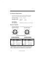
Connector Size/Type: Two 6 pin Mini DIN, one male, one female
6 Pin Mini Din Female
2
1
3
6 Pin Mini Din Male
4
5
1
2
4
6
3
6
5
Connector Pin Assignments
6 Pin Mini DIN Female
(connects to keyboard)
6 Pin Mini DIN Male
(connects to terminal)
Pin
Color
Function
Pin
Color
Function
1
3
4
5
Metal
Shield
Green
White
Red
Yellow
Cord
Drain
Keyboard data
Ground
V+
Keyboard clock
1
3
4
5
Metal
Shield
Blue
White
Red
Black
Cord
Drain
Terminal data
Ground
V+
Terminal clock
Cable shield♦
Cable shield♦
♦ Shield Isolation: The resistance between the shield and the power supply
common termination exceeds 1 meg ohm. The flashover voltage exceeds
40VDC. A 10KHz AC signal with an amplitude of 1.0 pp can be placed between the shield and the common termination with no operational affect.
A–2
Technical Specifications
Scanner Connector with Converter Cable Option
Connector Size/Type: Two 5 pin DIN, one male, one female
3
1
5
2
1
3
4
4
5 Pin DIN
Female
2
5
5 Pin DIN
Male
Connector Pin Assignments
5 Pin DIN Female
(connects to keyboard)
5 Pin DIN Male
(connects to terminal)
Pin
Color
Function
Pin
Color
Function
Shell
Braid
Shell
Braid
1
2
4
5
Yellow
Green
White
Red
Cord shield &
stainless handle♦
Keyboard clock
Keyboard data
Ground
+5VDC power
1
2
4
5
Black
Blue
White
Red
Cord shield &
stainless handle♦
Terminal clock
Terminal data
Ground
+5VDC power
♦ Shield Isolation: The resistance between the shield and the power supply
common termination exceeds 1 meg ohm. The flashover voltage exceeds
40VDC. A 10KHz AC signal with an amplitude of 1.0 pp can be placed between the shield and the common termination with no operational affect.
Technical Specifications
A–3
A.4 Environmental Specifications
Operating Temperature:
–4° F to +122° F (–20° C to +50° C)
Storage Temperature:
–40° F to +158° F (–40° C to +70° C)
Relative Operating
and Storage Humidity:
0% to 95% (non–condensing)
Shock:
Sustains 3 foot (91cm) drop
to a non–yielding surface
ESD:
17.5 KV to any external surface
Ambient Illumination:
3,000 Lux fluorescent (maximum)
1,500 Lux incandescent (maximum)
Barometric Pressure:
101,000 to 69,000 Pascals
(Sea level to 3000 meters)
Mean Time Between
Failure (Ground Benign):
137,419 hrs.
A.5 Mechanical Specifications
Weight:
7 ounces (196 grams) with cord
(maximum)
Interface Cable:
6 foot (1.83m) coiled cord
Cord Flexure:
Cord–scanner strain relief withstands in
excess of 1,000,000 flexures of
+90 degree flexure while stressed with a
weight of 6.7.
Scanner Dimensions:
Strain Relief
2380/J: 5.1 + .1 in. (130 + 3mm)
2380/K: 1.9 + .2 in. (48 + 5mm)
Sapphire tip: .41 + .01 in. (10.4 + .3mm)
A–4
Technical Specifications
A.6 Bar Code Symbol Specifications
All bar code symbols should satisfy the appropriate AIM Uniform
Symbology Specification.
Background Substrate
The bar code symbol should be printed on material which is reflective and
has a matte (not glossy) finish. A background diffuse reflectance of at least
70% to 80% is desirable for optimum contrast.
Ink Color and Type
The inked bars should not exceed 25% reflectance at the wavelength which
is being used for reading, whether printed with black ink or colored ink.
The reflectance value should not vary more than 5% within the same
character. The type of ink should be compatible with the type of radiation
in the optical scanner. If a scanner with an infrared radiation source is
being used, the ink in the code must be IR absorptive (typically carbon
based). Otherwise, the IR would “see through” the ink and be reflected to
the sensor as if from a completely white surface.
Voids and Specks
The code should be printed clearly, free of voids, specks, blemishes and
lines which could “fool” the scanner. Specks or blemishes in the white
spaces, or false or missing bar sections could be interpreted by the reading
equipment as part of the code. Generally, the width of such flaws is more
serious than the height. Code symbols should be rejected if these defects
are present.
Definition
The bars in the bar code symbol should be well defined. Their edges
should not be rough or fuzzy, so that the bars and spaces have the proper
widths intended for the bar code symbology used. Since a scanner’s
aperture and resolution are chosen to comply with these widths, definition
should be sharp and consistent.
Technical Specifications
A–5
Contrast
Background reflectance (that of the substrate on which the codes are
printed) should always provide a good contrast relative to the ink
reflectance (that of the code bars). The difference between the two should
be at least 37.5% at the wavelength used for reading.
Tolerance
The ratio of the widths of bars and spaces in a bar code symbol must
conform to the appropriate AIM bar code specifications and can cause
problems if not correct throughout the bar code. Problems can occur when
bar edges are smeared or rough, or when they exhibit voids.
A–6
Technical Specifications
KEYBOARD FUNCTION
RELATIONSHIPS
B
B.1 Keyboard Function Codes – Table 1
The following Keyboard Function Code, Function Record, and Full ASCII
“CTRL”+ relationships apply to all terminals that can be used with the
2380.
Keyboard
Function
Codes
Keyboard
Function
Records
NUL
SOH
STX
ETX
EOT
ENQ
ACK
BEL
BS
HT
LF
VT
FF
CR
SO
SI
DLE
DC1
DC2
DC3
DC4
NAK
SYN
ETB
CAN
EM
SUB
ESC
FS
GS
RS
US
#00
#01
#02
#03
#04
#05
#06
#07
#08
#09
#10
#11
#12
#13
#14
#15
#16
#17
#18
#19
#20
#21
#22
#23
#24
#25
#26
#27
#28
#29
#30
#31
Keyboard
Full ASCII
“CTRL” +
2
A
B
C
D
E
F
G
H
I
J
K
L
M
N
O
P
Q
R
S
T
U
V
W
X
Y
Z
3
4
5
6
7
Keyboard Function Relationships
B–1
B.1 Keyboard Function Codes – Table 2
Keyboard
Function
Codes
IBM, PS/2’s
PC/XT and PC/AT
Key Function
NUL
SOH
STX
ETX
EOT
ENQ
ACK
BEL
BS
HT
LF
VT
FF
CR
SO
SI
DLE
DC1
DC2
DC3
DC4
NAK
SYN
ETB
CAN
EM
SUB
ESC
FS
GS
RS
US
RESERVED
RESERVED
RESERVED
RESERVED
RESERVED
RESERVED
RESERVED
RESERVED
BACKSPACE
TAB FORWARD
END
PAGE UP
PAGE DOWN
NEW LINE (ENTER)
HOME
LEFT ARROW
RIGHT ARROW
DOWN ARROW
UP ARROW
F1
F2
F3
F4
F5
F6
F7
F8
ESCAPE
F9
F10
F11
F12
00
01
02
03
04
05
06
07
08
09
0A
0B
0C
0D
0E
0F
10
11
12
13
14
15
16
17
18
19
1A
1B
1C
1D
1E
1F
Keyboard Function Codes and records for the IBM PC, PC/XT, PC/AT,
PS/2 and compatible PC’s.
NOTE: These function codes are not compatible with other Welch Allyn
wedge products. If you are using other Welch Allyn wedge
products, or may be in the future, it would be advisable to program
the 2380 for K2 compatibility and use the function codes that are on
the following two pages.
B–2
Keyboard Function Relationships
B.1 Keyboard Function Codes – Table 3
Keyboard
Function
Codes
IBM AT/PS 2,
IBM 30, 50 – 80,
K2 Compatible
Key Function
NUL
SOH
STX
ETX
EOT
ENQ
ACK
BEL
BS
HT
LF
VT
FF
CR
SO
SI
DLE
DC1
DC2
DC3
DC4
NAK
SYN
ETB
CAN
EM
SUB
ESC
FS
GS
RS
US
RESERVED
ENTER (KP)
CAP LOCK
RESERVED
RESERVED
RESERVED
RESERVED
CR/ENTER
RESERVED
TAB
RESERVED
TAB
DELETE
CR/ENTER
INSERT
RESERVED
F11
HOME
PRINT
BACKSPACE
BACK TAB
F12
F1
F2
F3
F4
F5
F6
F7
F8
F9
F10
00
01
02
03
04
05
06
07
08
09
0A
0B
0C
0D
0E
0F
10
11
12
13
14
15
16
17
18
19
1A
1B
1C
1D
1E
1F
Keyboard Function Codes and records for the IBM AT and PS/2
compatibles.
NOTE: These function codes are compatible with other Welch Allyn wedge
products.
Keyboard Function Relationships
B–3
B.1 Keyboard Function Codes – Table 4
Keyboard
Function
Codes
IBM XT
K2 Compatible
Key Function
NUL
SOH
STX
ETX
EOT
ENQ
ACK
BEL
BS
HT
LF
VT
FF
CR
SO
SI
DLE
DC1
DC2
DC3
DC4
NAK
SYN
ETB
CAN
EM
SUB
ESC
FS
GS
RS
US
RESERVED
CR/ENTER
CAPS LOCK
RESERVED
RESERVED
RESERVED
RESERVED
CR/ENTER
RESERVED
TAB
RESERVED
TAB
DELETE
CR/ENTER
INSERT
RESERVED
RESERVED
HOME
PRINT
BACKSPACE
BACK TAB
RESERVED
F1
F2
F3
F4
F5
F6
F7
F8
F9
F10
00
01
02
03
04
05
06
07
08
09
0A
0B
0C
0D
0E
0F
10
11
12
13
14
15
16
17
18
19
1A
1B
1C
1D
1E
1F
Keyboard Function Codes and records for the IBM Xt’s and compatibles.
NOTE: These function codes are compatible with other Welch Allyn wedge
products.
B–4
Keyboard Function Relationships
B.1 Keyboard Function Codes – Table 5
Keyboard
Function
Codes
NUL
SOH
STX
ETX
EOT
ENQ
ACK
BEL
BS
HT
LF
VT
FF
CR
SO
SI
DLE
DC1
DC2
DC3
DC4
NAK
SYN
ETB
CAN
EM
SUB
ESC
FS
GS
RS
US
00
01
02
03
04
05
06
07
08
09
0A
0B
0C
0D
0E
0F
10
11
12
13
14
15
16
17
18
19
1A
1B
1C
1D
1E
1F
IBM 3196/97,
IBM 3476/77
(122 Key Keyboard)
Key Function
RESERVED
ENTER
F11
F12
F13
F14
F15
NEW LINE
F16
F17
F18
TAB/FIELD FORWARD
DELETE
FIELD EXIT
INSERT
F19
ERROR RESET
HOME
F20
BACKSPACE
BACKFIELD
F21
F1
F2
F3
F4
F5
F6
F7
F8
F9
F10
Keyboard Function Codes and records for the IBM 3176/77 and IBM
3476/77 with 122 key keyboards.
NOTE: These function codes are compatible with other Welch Allyn wedge
products.
Keyboard Function Relationships
B–5
B.1 Keyboard Function Codes – Table 6
Keyboard
Function
Codes
NUL
SOH
STX
ETX
EOT
ENQ
ACK
BEL
BS
HT
LF
VT
FF
CR
SO
SI
DLE
DC1
DC2
DC3
DC4
NAK
SYN
ETB
CAN
EM
SUB
ESC
FS
GS
RS
US
00
01
02
03
04
05
06
07
08
09
0A
0B
0C
0D
0E
0F
10
11
12
13
14
15
16
17
18
19
1A
1B
1C
1D
1E
1F
IBM 3191/92,
IBM 3471/72
(122 Key Keyboard)
Key Function
RESERVED
ENTER
F11
F12
F13
F14
F15
NEW LINE
F16
F17
F18
TAB
DELETE
NEW LINE
INSERT
F19
ERROR RESET
HOME
F20
BACKSPACE
BACK TAB
F21
F1
F2
F3
F4
F5
F6
F7
F8
F9
F10
Keyboard Function Codes and records for the IBM 3191/92 and IBM
3471/72 with 122 key keyboards.
NOTE: These function codes are compatible with other Welch Allyn wedge
products.
B–6
Keyboard Function Relationships
B.1 Keyboard Function Codes – Table 7
Keyboard
Function
Codes
NUL
SOH
STX
ETX
EOT
ENQ
ACK
BEL
BS
HT
LF
VT
FF
CR
SO
SI
DLE
DC1
DC2
DC3
DC4
NAK
SYN
ETB
CAN
EM
SUB
ESC
FS
GS
RS
US
00
01
02
03
04
05
06
07
08
09
0A
0B
0C
0D
0E
0F
10
11
12
13
14
15
16
17
18
19
1A
1B
1C
1D
1E
1F
IBM 3196/97, 3476/77,
IBM 3491/92, 3471/72
(102 Key Keyboard)
Key Function
RESERVED
ENTER
F11
F12
F13
F14
F15
NEW LINE
F16
F17
F18
TAB/FIELD FORWARD
DELETE
FIELD EXIT
INSERT
CLEAR
ERROR RESET
HOME
PRINT
BACKSPACE
BACK TAB
F19
F1
F2
F3
F4
F5
F6
F7
F8
F9
F10
Keyboard Function Codes and records for the IBM 3196/97, 3476/77,
3191/92, and 3471/72 with 102 key keyboards.
NOTE: These function codes are compatible with other Welch Allyn wedge
products.
Keyboard Function Relationships
B–7
B.1 Keyboard Function Codes – Table 8
Keyboard
Function
Codes
DEC VT 220/320
/340 Terminals
Key Function
NUL
SOH
STX
ETX
EOT
ENQ
ACK
BEL
BS
HT
LF
VT
FF
CR
SO
SI
DLE
DC1
DC2
DC3
DC4
NAK
SYN
ETB
CAN
EM
SUB
ESC
FS
GS
RS
US
RESERVED
ENTER
PF1
PF2
PF3
F11
F12
NEW LINE
PF4
TAB
F13
F14
REMOVE
NEW LINE
INSERT HERE
CURSOR UP
CURSOR LEFT
CURSOR DOWN
CURSOR RIGHT
DELETE
PRINT
F15
F1
F2
F3
F4
F5
F6
F7
F8
F9
F10
00
01
02
03
04
05
06
07
08
09
0A
0B
0C
0D
0E
0F
10
11
12
13
14
15
16
17
18
19
1A
1B
1C
1D
1E
1F
Keyboard Function Codes and records for the DEC VT 220/230/240
terminals.
NOTE: These function codes are compatible with other Welch Allyn wedge
products.
B–8
Keyboard Function Relationships
INDEX
Bar Code Symbol Specifications,
A–5
Background Substrate, A–5
Contrast, A–6
Definition, A–5
Ink Color and Type, A–5
Tolerance, A–6
Voids and Specks, A–5
Bar Code Symbology, 1–3
Cleaning, 5–1
Electrical Specifications, A–2
Operating Current, A–2
Operating Voltage, A–2
Power Supply Noise Rejection,
A–2
Scanner Connector
Environmental Specifications, A–4
Ambient Illumination, A–4
Barometric Pressure, A–4
ESD, A–4
Humidity, A–4
Mean Time Between Failure, A–4
Operating Temperature, A–4
Shock, A–4
Storage Temperature, A–4
Factory Service, 5–4
See also Warranty Information
Hardware Description, 1–1
Inspection, 5–2
Cords and Connectors, 5–2
Scanner Case, 5–2
Keyboard Function Codes, B–1
Keyboard Wedge Connection, 1–2
Main Elements of 2380, 2–1
Maintenance and Service, 5–1
See also Cleaning and Inspection
Mechanical Specifications, A–4
Cord Flexure, A–4
Interface Cable, A–4
Scanner Dimensions, A–4
Weight, A–4
Non–Volatile Memory, 1–3, 4–1
Operating Theory, 2–2
Operational Description, 2–1
Optical Specifications, A–1
Depth of Field, A–1
Light Source, A–1
Tilt Angle, A–1
Programming Menu, 4–1
Bar Code Chart, 4–4
COMM 1, 4–12
COMM 1 Menu Page
Foreign Keyboards, 4-12
Intermec Capability, 4-13
Configuration Example, 4–16
Direct Connect, Terminal
Selection, 4–6
Direct Connect Terminal
Selection, 4–6
Facing Page, 4–4
Keyboard Layouts and Delimiters,
4–18
Message Format, 4–15
Output Parameters & Format, 4–6
Append Buffer, 4-12
Beeper, 4-11
Function Transmit, 4-8
Intercharacter Delay, 4-11
Interfunction Delay, 4-11
Intermessage Delay, 4-11
Keyboard Function Records,
4-9
Scanner Data, 4-10
Keyboard Type, 4-10
LEDs/Beeper
Beep on Good Read, 4-11
Beep/Blink on Reset, 4-11
Postamble, 4-7
Preamble, 4-6
Code ID, 4-7
Programming Menu Pages, 4–1
Scancode Selection, 4–13
Beep PC, 4-13
K2 Scancode Capability, 4-13
New Keyboard Scancode
Table, 4-13
Numeric Keypad, 4-13
RX Interrupt, 4-14
Symbology Selection, 4–14
Maximum Length, 4-14
Minimum Length, 4-14
Terminal Selection, 4–6
Programming the Scanner, 4–1
Scanner Checks, 3–3
Check Bar Code Labels, 3–3
Confirm Scanner Operation, 3–3
Scanner Dimensions. See
Mechanical Specifications
Scanner Identification Key, 2–2
Scanner Performance, A–1
Scanning Performance Influences,
2–2
Depth of Field, 2–4
High Density Bar Codes, 2–4
Illumination Source, 2–2
Low Density Bar Codes, 2–4
Print Contrast, 2–5
Scanning Aperture, 2–3
Scanning Velocity, 2–4
SCANTEAM 2380/J and 2380/K,
1–4
Set–Up and Installation, 3–1
Software Description, 1–3
SRD scanner, 1–4
Technical Specifications, A–1
Troubleshooting, 5–2
Wand Models, 1–4
Warranty Information, i
Y Cable Interface Connections, 3–2
2380/TM
Rev E
Data Collection Division
4619 Jordan Road
P.O. Box 187
Skaneateles Falls, New York 13153–0187