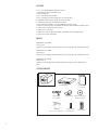
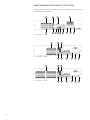
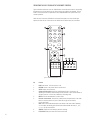
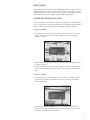
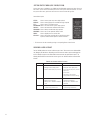
1
120XXN-Series
©2008 i³DVR International Inc.
The contents of this user manual are protected under copyrights and
computer program laws.
INNOVATIONS AT THE SPEED OF THOUGHT
®
TABLE OF CONTENTS
Precautions............................................................................................
Description ............................................................................................
Features ................................................................................................
Models .................................................................................
System Contents....................................................................
Overview of the System .........................................................................
4
5
6
6
6
7
Veo 120XXN Controls .............................................................................
Controls on the Front Panel of the Veo 120XXN ........................
Connection Ports on the Back Panel of the Veo 120XXN ............
Operating the Veo 12008N/12016N with the Mouse .................
Operating the Veo 120XXN with the Remote Control.................
8
8
10
11
12
Before You Begin ................................................................................... 13
Starting and Stopping the Veo 120XXN ................................... 13
System Context Menu (Veo 12008N/12016N)...........................
14
Choosing a User Account ........................................................ 14
Main Window Overview ......................................................................... 15
Changing the Display Mode ..................................................... 15
Sequencing Mode .................................................................. 16
Adjusting Menu Settings ......................................................... 16
OSD (On-Screen-Display) menu ................................ 17
Monitor menu ....................................................... 18
Sequence menu ..................................................... 18
Spot-out menu ...................................................... 19
Camera menu ....................................................... 19
Audio menu .......................................................... 21
Buzzer menu ......................................................... 21
System menu ........................................................ 21
Event/Sensor menu................................................. 24
Disk Manage menu ................................................ 25
Record menu ......................................................... 25
Archiving menu ...................................................... 27
Adding Users/Changing Passwords ...........................................................
28
Controlling Cameras from the Veo 120XXN ..............................................
Pan, Tilt and Zoom Controls ....................................................
Adjusting the Focus or Iris on a Camera ....................................
Working With Presets ............................................................
Modifying Recording Schedules ...............................................................
Setting Up Timer/Motion-Based Recording and Parameters ........
Setting Up Alarm-Based Recording and Parameters ...................
Setting Up Motion Detection Recording Regions.........................
31
31
33
33
Working With Recorded Video .................................................................
Searching for Video ................................................................
Playing Recorded Video Using the Front Panel/Remote Control....
Backing Up Video ...................................................................
34
34
36
37
29
29
30
30
Factory Default Settings ......................................................................... 39
Exporting/Importing System Settings ........................................................ 39
Viewing Video With Windows™ Media Player™.......................................... 40
LIST OF FIGURES
1 Package Contents ................................................................................. 6
2 Connecting Devices to the Veo 120XXN .................................................. 7
3 Connecting Veo Systems Across the Internet ........................................... 7
4 Front Panel of the Veo 12004N .............................................................. 8
5 Front Panel of the Veo 12008N .............................................................. 8
6 Front Panel of the Veo 12016N .............................................................. 8
10
7 Back Panel of the Veo 12004N ....................................................................
10
8 Back Panel of the Veo 12008N ....................................................................
10
9 Back Panel of the Veo 12016N ....................................................................
10 Remote Control Operation ................................................................... 12
11 Logging In as the Administrator ............................................................ 13
12 Shutdown Screen ............................................................................... 13
13 System Context Menu ......................................................................... 14
14 Veo 120XXN Main Window ................................................................. 15
15 Screen Display Modes ......................................................................... 15
16 Main Menu - General .......................................................................... 16
17 OSD Display Menu .............................................................................. 17
18 Monitor Display Menu ......................................................................... 18
19 Sequence Display Menu ....................................................................... 19
20 Add New Sequence Display Menu ......................................................... 19
21 Spot Out Display Menu ........................................................................ 19
22 General Camera Menu ........................................................................ 19
23 Camera Title Menu ............................................................................. 19
24 Virtual Keyboard ................................................................................. 19
25 Virtual Keyboard Instructions ................................................................ 19
26 Colour Setup Camera Menu .................................................................. 20
27 Colour Adjustment Window .................................................................. 20
28 PTZ Setup Camera Menu ..................................................................... 20
29 PTZ Property Window ......................................................................... 20
30 Motion Sensor Camera Menu ............................................................... 20
31 Audio Sound Menu ............................................................................. 21
32 Buzzer Sound Menu ............................................................................. 21
33 System Menu ..................................................................................... 21
34 Date/Time System Menu ..................................................................... 22
35 Overlapped Date Erased Display ........................................................... 22
36 Network Menu ................................................................................... 22
37 Mail System Menu .............................................................................. 23
38 User Management System Menu .......................................................... 23
39 System Management System Menu ...................................................... 23
40 Control Device System Menu ................................................................ 23
41 Alarm Out Event/Sensor Menu ............................................................ 24
42 Buzzer Out Event/Sensor Menu ............................................................. 24
43 Email Notification Event/Sensor Menu ................................................... 25
44 Disk Manage Menu ............................................................................. 25
45 Recording Operations Menu ................................................................. 25
46 Timer/Motion Setup ........................................................................... 26
47 Alarm Setup........................................................................................ 26
48 Main Menu - Archiving ........................................................................ 27
49 Archiving Menu .................................................................................. 27
50 User Management - Adding/Editing User Menu ..........................................
51 PTZ Control Menu... ...............................................................................
52 Focus/Iris Control Menu ..........................................................................
53 Timer/Motion Recording Menu .................................................................
54 Recording Parameters Setup ...................................................................
55 Timer/Motion Setup - Schedule Type Selection ..........................................
56 All 16 Channels Record Continuously ........................................................
57 All 16 Channels Record Based on Motion ..................................................
58 Alarm Recording Menu ...........................................................................
59 Motion Sensor Camera Menu ..................................................................
60 Motion Detection Region Window ............................................................
61 Motion Detection Region Setup ...............................................................
62 Search by Time Menu ............................................................................
63 Search by Event Menu ............................................................................
64 Search by Event, Results Window ............................................................
65 Video Control Buttons ............................................................................
66 Jog/Shuttle Dial With Hold Button ...........................................................
67 Archiving Menu .....................................................................................
68 Archive Files List ....................................................................................
69 Writing Backup Data Onto Media ............................................................
70 System Management Menu ....................................................................
71 Windows Screen ...................................................................................
72 Codec Installation Wizard ........................................................................
73 Enabling Video Captions .........................................................................
74 Windows Media Player AVI Video Captions ...............................................
28
29
30
31
31
32
33
33
33
33
34
34
35
35
36
36
36
37
38
38
39
40
40
40
40
LIST OF TABLES
A User Accounts and Access Levels .................................................................. 14
B Settings for Recording Video ........................................................................ 26
C Image Sizes and Maximum Recording Rates ................................................... 32
PRECAUTIONS
Please read before operating the Veo Digital Video Management System (DVMS).
The following precautions MUST be observed in order to prevent personal injury and/or damage to the
Veo DVMS.
Please avoid these conditions when selecting a storage location for your system:
• Excessive heat, such as direct sunlight or heating appliances
• Moisture, dust, and smoke
• Magnetic fields or electrical waves
• Temperature below 0º C or 32º F
• Obstruction to the system’s ventilation hole
• Uneven surfaces and surfaces where the system may be subjected to vibration
!
WARNING:
• Do not attempt to dismantle or disassemble the DVMS
• Do not use without Uninterrupted Power Supply (UPS). Failing to use UPS will result in voided
warranty.
• Do not attempt to repair the DVMS. Contact your dealer/installer for technical support and/or
repairs.
• Do not drop the system or subject the system to strong vibration.
• Do not unplug the system without turning the power off first.
• Do not use the power cords and extension cords without a ground connection
!
WARNING: RISK OF EXPLOSION
• There is a risk of explosion if the battery is replaced with the incorrect type
of battery.
• Only a certified technician should attempt replacing the battery inside the
system.
• Check the lithium battery polarity before installing.
!
CR
2016
3V
WARNING:
To avoid electric shock, turn off and unplug the unit while connecting devices to the Veo 120XXN.
Adequate ventilation is required for proper operation of the Veo 120XXN. Allow two inches of space
above the unit and on each side for air circulation.
DESCRIPTION
The Veo 120XXN Series digital video recorder (DVR) is a professional, yet easy to use digital video
recorder that replaces the traditional VCR and multiplexer combination by offering the excellence and
flexibility of the latest digital video recording advancements.
One of the critical benefits of the Veo 120XXN is the usage of MPEG-4 video compression, which not
only allows the user the ability to view and control the DVR over the wide area network but also results
in a smaller video file sizes. The smaller file sizes, in turn, allow for longer storage times as compared
with other digital video compression technologies.
Additionally, the Veo 120XXN Series allows recording video at resolutions up to 704x480, which yields
sharp and clear images, creating high quality footage for later use and retrieval. Full-motion video can
be recorded in CIF resolution (352x240 NTSC, 352x288 PAL), since Veo 120XXN Series supports the
recording speed of up to 120 frames per second. Moreover, this unit allows customizing the recording
frame rate individually for each video input. This, in turn, ensures that the specific custom requirements
for length of video retention for each given installation are met. For investigation or archiving purposes,
video recordings can be easily exported to external storage, such as DVD-R, CD-R or USB flash.
With the ability to control pan/tilt/zoom (PTZ) cameras such as the daVinci domes, the Veo 120XXN has
the potential to become a powerful control tool in any surveillance installation. In addition, this DVR
can trigger video recording and/or alarms based on motion or external contacts, which transforms Veo
120XXN into an automated monitoring and notification device.
This versatile unit offers the choice of VGA, S-Video and composite main monitor outputs. The main
monitor output can be configured to display video inputs in MUX mode (quad screen) or in sequential
mode (full screen). This DVR’s spot monitor can serve as an effective control and as a deterrent to
potential perpetrators.
In conclusion, the Veo 120XXN is designed to meet the performance and reliability expectations of the
security industry professionals. Combining invaluable security features such as the ability to capture log
entries for any changes to the system, and user access management, the Veo 120XXN series represents
the entry-level digital video recorder capable of protecting assets and people.
FEATURES
• 4-, 8-, or 16-channel full duplex digital video recorder
• 4-channel audio inputs with one audio output
• MPEG-4 compression
• Up to 704 x 480 Recording Resolution
• Up to 120 images per second recording rate at 352 x 240 resolution
• Independent channel resolution, quality, and frame rate settings
• Full-function remote agent with administration functions
• Up to 640 GB (Veo 12004N) or 2 TB (Veo 12008N/12016N) internal storage
• Support for continuous, motion, and scheduled recording for maximum utilization of hard disk drives
• Local or remote PTZ control via Pelco D protocol
• 4 alarm inputs, 1 relay output
• Main monitor output configurable for multiple-camera displays for live and playback video
• Spot monitor for public view displays
MODELS
Model Number: Veo 12004N
Camera Input: 4
Description: 4-channel digital video recorder with 320 GB of storage space and 1 DVD/CD writer device
Model Number: Veo 12008N
Camera Input: 8
Description: 8-channel digital video recorder with 500 GB of storage space and 1 DVD/CD writer device
Model Number: Veo 12016N
Camera Input: 16
Description: 16-channel digital video recorder with 500 GB of storage space and 1 DVD/CD writer
device
SYSTEM CONTENTS
Shipping Box
Veo 120XXN Series
Standard Power
Cord (110 VAC)
USB Mouse
(Shipped only with Veo 12008N/12016N)
Figure 1. Package Contents
12 VDC Adapter
Operation Manual
(this manual)
Resource CD with Client
Software and Manual
2 x AAA Batteries
for Remote Control
Remote Control
OVERVIEW OF THE SYSTEM
The Veo 120XXN unit serves as the center point of the video surveillance system, to which remote
client computers can be connected. Please note that a maximum of four client computers can be connected to a single Veo 120XXN unit at each given time. Figure 3 illustrates the network connectivity
for Veo 120XXN. As per the diagram, remote computers can be connected either directly to the Veo
120XXN via router or remotely over the network. Please refer to Figure 3 for an example on how one
or more computers can be connected to the Veo 120XXN over the Internet.
Figure 2 shows the maximum number of cameras and alarm sensors that can be connected to the Veo
120XXN system. Veo 120XXN also allows for a number of spot monitors to be connected to the system
for live viewing of the video inputs.
The Veo 120XXN supports two types of backup devices: CD/DVD burner and a USB flash memory
device, which can be connected via USB port on the front system panel.
REMOTE CLIENT PC
(VEO REMOTE)
ALARM SENSOR #1-4
USB MOUSE
(12008N/12016N)
REMOTE
CONTROLLER
AVI
BACKUP
VEO 120XX
NETWORK
MONITOR
CAMERAS
#1-4 (Veo 12004N)
#1-8 (Veo 12008N)
#1-16 (Veo 12016N)
IMAGE PRINTER
DVD-RW
USB KEY
AV MONITOR
Figure 2. Connecting Devices to the Veo 120XXN
ROUTER
CLIENT PC
NETWORK
xDSL MODEM
CLIENT PC
MONITOR
VEO 120XXN
Figure 3. Connecting Veo 120XXN Systems Across the Internet
VEO 120XXN CONTROLS
CONTROLS ON THE FRONT PANEL OF THE VEO 120XXN
The buttons on the front panel of the unit are used to control PTZ and camera focus, to enter menus
and adjust settings on the Veo 120XXN, and to search for and play back video. Refer to Figures 4-6 for
the locations of the buttons on the front panel.
5
3
2
1
7
6
4
CH 1
EJECT
CH 2
8
CH 3
CH 4
PWR
REC
NET
ALM
SCREEN
MODE
SEARCH
MENU
PTZ/
FOCUS
HOLD
USB
JOG/SCHUTTLE
12004
Figure 4. Front Panel of Veo 12004N.
9
1
Figure 5. Front Panel of Veo 12008N.
10 11
12
3
5
4
2
9
10
7
11
12
Figure 6. Front Panel of Veo 12016N.
9
2
4
10
13 14 15 16
17
8
17
7
5
3
1
6
13 14 15 16
7
11
6
12
13 14 15 16
7
8
17
No. Function
1.
2.
3.
4. 5.
6.
7.
8.
9.
10.
11.
12.
13.
14.
15.
16.
17.
USB port: USB port for the USB flash memory device and USB HDD backup.
On Veo 12008N/12016N models, USB port is also used to connect the USB mouse.
Rewind: Plays the video in reserve at a fast speed. In the PTZ/FOCUS control mode, this
button allows user to zoom out.
Reverse playback: Plays the video in reverse with normal speed or navigates the system
menus (left).
Increase playback speed: Increases the playback speed (forward or reverse) or navigates
the system menus (up).
Play forward: Plays the video forward with normal speed or navigates the system menus
(right).
Fast forward: Plays the video forward at a fast speed. In the PTZ/FOCUS control mode,
this button allows user to zoom in.
Channel selection buttons: Selects the available channels or allows entering the user password. The number of channel selection buttons will vary based on Veo model.
LED Indicators: Indicates present system status:
PWR: Power – system on/off,
REC: Record – video recording on/off,
NET: Network – when remote clients are connected to the system this LED is lit green.
ALM: Alarm – alarm sensor on/off
JOG HOLD: Jog Shuttle hold. Adjust the playback speed with Jog Shuttle, then press
HOLD button to hold the current speed.
RETURN: Returns to the previous menu or cancels action.
PAUSE: Freezes the video recording playback and displays the current video frame.
Decrease playback speed: Decreases the playback speed (forward or reverse) or navigates
the system menus (down).
ENTER: Enters the menu/submenu or confirms action.
SCREEN MODE/DISPLAY: Selects screen mode between split screen division or full screen
modes. Depending on a Veo model, the following split screen divisions will be available: full
screen, 4-, 6-, 8-, 9-, 13-, or 16 split screen division.
SEARCH: Displays the search mode for video data searching.
MENU/SETUP: Displays the system menu.
PTZ/FOCUS: Displays the camera PTZ/FOCUS control mode.
JOG SHUTTLE: Controls the playback (forward or reverse) speed. Turn the dial clockwise
to increase the forward playback speed, turn the dial counter clockwise to increase the
reverse playback speed. The following playback speeds are available: x1, x2, x,4, x8, x16,
x32, and x64.
CONNECTION PORTS ON THE BACK PANEL OF THE VEO 120XXN
To determine how to connect devices to the unit, please refer to the diagrams of the rear panels of the
Veo 120XXN-series units (Figures 7-9).
1
3
2
4
11
6
5
7
8
9
10
12
13
Figure 7. Back Panel of Veo 12004N.
1
Figure 8. Back Panel of Veo 12008N.
1
Figure 9. Back Panel of Veo 12016N.
10
3
9
4
8
3
9
4
8
11
10
6
13
11
10
6
13
No. Function
1.
2.
3.
4.
5.
6.
7.
8.
9.
10.
11.
12.
13.
VIDEO IN: BNC Input for Cameras. The number of BNC Inputs will depend on the Veo
model and will vary between 4, 8 and 16.
LOOP OUT: BNC Loop out for Cameras 1-4. Available only on Veo 12004N.
Monitor Out: BNC Output Video to AV Monitor.
Spot Out: BNC Spot-out Video to AV Monitor.
NTSC/PAL: Video mode selector. Available only on Veo 12004N. Veo 12008N/12016N
models have an automatic built-in NTSC/PAL selector.
VGA OUT: Video Output to a VGA Monitor.
SVHS: Output Video via S-Video Connector. Available only on Veo 12004N.
Audio Out: RCA Audio Output.
Audio In: RCA Audio Inputs. The number of RCA Audio Inputs will depend on the Veo
model: Veo 12004N has 4 audio inputs, Veo 12008N/12016N has 2 audio inputs.
Ethernet (TCP/IP): RJ45 connector for Network Connection.
Alarm/Relay/RS-485: Terminals for Sensor, Relay, & PTZ connection.
RS-232C: Connect Port for Program Debug. Available only on Veo 12004N.
DC Power Input: Power Supply by DC 12V Adaptor.
OPERATING THE VEO 12008N/12016N WITH THE MOUSE
Veo 12008N/12016N models can be operated with the USB mouse that is included with the unit. Note
that there is only one USB port available on each unit, which means that if the user wants to backup
their data onto a USB storage media, the USB mouse must first be unplugged.
To access the unit’s menu, right-click on the main screen. Use the mouse to highlight and select menu
options, to define motion detection area, etc.
NOTE
USB mouse is not included and is not
supported by Veo 12004N models.
11
OPERATING THE VEO 120XXN WITH THE REMOTE CONTROL
Figure 10 describes the buttons on the Veo 120XXN remote control. Most buttons have a corresponding
button/function on the front panel of the unit. Buttons that are not usable are not described. The tone
sound for remote control and front panel buttons can be enabled/disabled in the system menu as per
customer preference.
Please note that if several Veo 120XXN units are located close together, the remote control might
operate more than one unit. Ensure that the Veo 120XXN units are located away from one another.
1
PWR
SETUP
1
2
3
4
5
6
7
8
9
3
4
0
2
5
ENTER
RETURN
6
7
DISP
SEARCH
P/T/Z
PANIC
KEYLOCK
SEQUENCE
ZOOM
ARCHIVE
9
8
DISP
SEARCH
P/T/Z
KEYLOCK
SEQUENCE
ZOOM
OSD
ARCHIVE
Figure 10. Remote Control Operation
12
No. Function
1.
2.
3.
4.
5.
6.
7.
8.
9.
PWR: Power button. Turns the system on or off.
RETURN: Returns to the previous menu or cancels action.
SETUP: Displays the system setup.
Channel selection buttons: Selects the available channel(s) up to a maximum of 16
depending on the model) or allows entering the user password. To enter channel number 10 and above, press the ‘1-’ button first, followed by a second digit (0-6).
ENTER: Enters the menu/submenu or confirms action.
Direction control buttons: The functions of these buttons correspond exactly to the similar
buttons on the front panel of the system. Please refer to page 8 of this manual
for more information.
DISP: Selects screen mode between split screen division or full screen modes. Depending
on a Veo model, the following split screen divisions will be available: full screen, 4-, 6-, 8-,
9-, 13-, or 16- split screen division.
SEARCH: Displays the search mode for video data searching.
PTZ/FOCUS: Displays the camera PTZ/FOCUS control mode.
BEFORE YOU BEGIN
This manual describes the menus of the Veo 120XXN and provides instructions on how to control PTZ
movement and focus cameras, how to search for, play back, and back up video directly from the Veo
120XXN. The manual also provides instructions on how to configure your Veo 120XXN unit and how to
review exported (backed-up) video recording in the Windows Media Player application.
STARTING AND STOPPING THE VEO 120XXN
The first time you start the Veo 120XXN, you must log in as the administrator. The default password
is 1234. For information on how to add/change passwords, refer to Adding Users/Changing Password on
page 28. A maximum of four users may be logged on simultaneously through the remote client.
To start the Veo 120XXN
1.Press any button on the front panel of the Veo 120XXN, or press the PWR button on the remote
control, if the unit is not already running. The Menu screen appears and the appears and the
ADMIN user is selected.
Figure 11. Logging In as the Administrator
2.If desired, press the up or down arrow to select a different user ID (only the ADMIN will appear at
first power-on of the unit)
3.Press the channel buttons on the front panel or numbered buttons on the remote control to enter
your password, and then press ENTER button. Unless it has been changed, the default password is
1234.
To stop the Veo 120XXN
1.Using the remote control, press the PWR button. Using the USB mouse (if applicable), right-click
on the main screen and select the SHUTDOWN option from the context menu. The Shutdown
prompt screen will appear.
Figure 12. Shutdown Screen
2.Using the front panel buttons or the remote control, enter the administrator password (Default
Password is 1234). If there are multiple administrators, choose the appropriate account and enter
the password. The unit will shut down and then turn off.
13
SYSTEM CONTEXT MENU (VEO 12008N/12016N)
System context menu is available on Veo 12008N and 12016N models through mouse right-click on the
main screen. System context menu allows quick access to the system’s most used functions. To access
the system context menu, position the mouse cursor on the main screen and right-click.
Context Menu Options:
SETUP*:
Select to access system setup menu (login required)
SEARCH*: Select to search and play back recorded video (login required)
PTZ*: Select to enter PTZ navigation screen
SHUTDOWN: Select to shut down the Veo system (login required)
DISPLAY*: Select to switch between available screen divisions
ARCHIVING*: Select to backup recorded video (login required)
SEQUENCE*: Select to turn on the sequential channel rotation
ZOOM*: Select to digitally zoom into the live video
KEY LOCK*: Select to lock remote controller and front panel buttons (login
required). Password will be required to unlock the buttons.
Figure 13. System Context Menu
* - This feature can also be accessed by pressing a corresponding Remote Control button.
CHOOSING A USER ACCOUNT
The Veo 120XXN provides user accounts for different types of users. There are three access levels available:
User, Manager, and Administrator. Depending on what actions the user needs to perform while logged into
the Veo 120XXN, the proper account level should be chosen that offers the required level of access. The
following table describes the access levels for each user type for Veo 120XXN as well as the Remote Client
software.
Table A. User Accounts and Access Levels
14
User Account
Veo 120XXN
Remote Client Software
User
• View live video
• Change the screen display mode
• Control cameras (PTZ, focus, and iris)
• View live video
• Change the screen display mode
• Control cameras (PTZ, focus, and iris)
• Adjust color
• Control audio
• Save video to the local drive
• Change network connection settings
Manager
• All user access
• Search for recorded video
• Backup video to CD/DVD or USB flash
drive
• All user access
• Search for recorded video
• Back up video to CD/DVD or USB
flash drive
Administrator
• Complete access to all Veo 120XXN
system settings and functions
• Complete access to all Veo 120XXN
system settings and functions
MAIN WINDOW OVERVIEW
1
2
3
5
4
Figure 14. Veo 120XXN Main Window. This view may vary depending on the model
The Veo 120XXN main window provides access to current system information.
1.Camera title: Displays the name of the camera. The camera title is displayed for each
camera that is connected to the Veo 120XXN.
2.Recording status: Indicates that the video from a specific camera is being recorded. A red square
indicates that the video is being recorded; green indicates that the video is being pre-recorded into a
buffer. The recording status appears for each camera that is connected to the Veo 120XXN.
3.Date and Time: Indicates the current date and time when viewing live video. This
information changes when viewing recorded video.
4.Network Status: Indicates the system network status. If there are users connected to the
Veo 120XXN remotely, it is indicated with an amber circle beside the two networked computer icons
on the main screen. In addition, the NET LED light on the front panel is lit green when the remote
client(s) is (are) connected to the system.
5.Hard Disk Status: Indicates the estimated amount of storage space used on the hard disk.
CHANGING THE DISPLAY MODE
The display mode on the Veo 120XXN is preset to display all available channels simultaneously. You
can change this screen mode to display one of the available split screen divisions (dependent on the Veo
model): single (full-screen), 4- (quad), 6-, 8-, 9-, 13-, or 16-channel screen division.
Figure 15. Screen Display Modes
15
To change the screen display mode
1.Using remote control, press the DISP button; using Veo 120XXN front panel, press DISPLAY button or
right-click on the main screen and select DISPLAY option from the context menu. The display will change
to a single-channel display.
2.Repeat step 1 until the desired screen display appears.
To view a specific channel, press the corresponding channel button on the Veo front panel or on the
remote control. Please refer to the Remote Control section on page 12 for more information.
SEQUENCING MODE
Default sequencing mode allows rotating all available channels in the full screen mode on the main
screen. Additional custom sequencing modes may be created in Display Menu.
To select Sequencing Mode, right-click on the Main Screen and select SEQUENCE option from the
context menu or press SEQUENCE button on the remote controller.
The sequencing dwell time determines how long each channel (screen display) will be displayed on the
screen. The default dwell time for sequencing mode is set to 3 seconds. The default sequencing dwell
time can be changed in the Display -> Monitor menu.
ADJUSTING MENU SETTINGS
Figure 16. Main Menu
To access menus on the Veo 120XXN, press the SETUP button on the front panel/remote control or
right-click on the main screen and select SETUP from the context menu. Select GENERAL from the
main menu screen. Each menu contains settings related to a different function on the Veo 120XXN.
These menus are described below.
NAVIGATING VEO SETUP
To navigate the menus and sub-menus, use the mouse, ARROW buttons on the front panel of the unit
or on the remote control.
Use the USB mouse (with supported models only) for the complete ease of navigation. To enter the
sub-menu or click a button on the user interface, click it with the mouse cursor or select it and press
the ENTER button on the front panel/remote control.
16
To change the parameter anywhere within the menu, select it and press the ENTER button. This will
activate the editing mode: the green box around the parameter will change to yellow. This means that
the setting can now be adjusted. To adjust, use the ARROWS Up/Down to browse through available
settings. Keep pressing the Up/Down ARROWS until the desired setting is selected, then press the
ENTER key to exit the editing mode.
To save the changed parameters, always select APPLY option in the menu screen and press the ENTER
button before closing out of the menu.
To discard the changes, press RETURN button to close out of the menu screen without saving.
OSD (ON-SCREEN-DISPLAY) MENU
Figure 17. OSD Display Menu
OSD (On-Screen Display)
Status bar: Turn this setting ON to display the status bar on the bottom of the screen.
The setting affects all video panes, i.e. live or playback modes.
•
•Camera Title: Turn this setting ON to display the camera title (if it exists). The setting affects all
cameras connected to the Veo 120XXN. To set up a camera title, use the Camera Menu. Please
refer to page 19 for more information
Event Icon: Turn this setting ON to display the video recording status on the main screen. A red
square indicates that the video is being recorded; green indicates that the video is being pre recorded into a buffer. The recording status appears for each camera that is connected to
the Veo 120XXN.
•
Border: Turn this setting ON to display the border between each camera view in the quad display mode.
•
Border Color: Select the border color for the multi-screen divisions. Choices are White, Blue, Red, Yellow, Green, and Gray.
•
Menu Transparency: Select the level of transparency (0-100) of the menu display and the status bar on the video pane. The higher the value, the more transparent the menu display becomes.
•
•
Motion Sensor: Set the Motion Sensor to either OFF, ACTIVE or INACTIVE.
OFF: No visual alert is displayed when the motion is detected in the configured area.
ACTIVE: Area blocks with detected motion are colored on the screen.
INACTIVE: Area blocks without motion are colored on the screen.
In order for this function to work, motion detection area has to be configured for chosen cameras in
Motion Sensor setup (see page 33).
Motion Color: Set the Motion Color to Red, Green, Blue or Yellow. This color pertains to the
Motion Sensor function.
•
Motion Transparency: Set the Motion Transparency to 0, 1, 2, or 3, where 3 is solid and 0 is
transparent. This function determines the transparency of the motion sensor color.
•
17
MONITOR
Figure 18. Monitor Display Menu
•
Sequence Dwell: Set the time interval that each camera/screen division will be displayed before the
Veo 120XXN switches to the next video input in sequence. This setting is used when the sequence
display mode is used in live mode. Sequence dwell time can be configured between 1 and 60
seconds. This setting applies to the monitors that can be connected to the VGA OUT, MONITOR
OUT (BNC) and SVHS (S-Video - Veo 12004N only) ports in the back of the system.
Spot-Out Dwell: Set the time interval that each camera will be displayed on the spot monitor
before the Veo 120XXN switches to the next video input in sequence (1-60 seconds). This setting
applies to the monitors that can be connected to the SPOT OUT (BNC) port in the back of the
system.
•
•De-Interlace Mode: Turn this setting ON to remove the screen spread if you are recording at a high
resolution (704 x 480) and a low frame rate.
•Alarm Pop-up Mode: Turn this setting ON to display the corresponding camera in the full screen
mode each time the alarm is triggered. For example, if Alarm Input #1 is triggered, Camera 1 is
displayed in the full screen mode. This setting does not affect the spot monitor display.
•Alarm Pop-up Dwell: Set the time interval that the Alarm Channel will remain in the full screen
mode (1-60 seconds).
Motion Pop-Up Mode: Turn this setting ON to display the corresponding camera in the full screen
mode on the VGA OUT and MONITOR OUT displays each time the motion is detected. This setting does not affect the spot monitor display.
•
•Motion Pop-up Dwell: Set the time interval that the Motion Channel will remain in the full screen
mode (1-60 seconds).
SEQUENCE
Each Veo 120XXN comes with a default sequence, which displays each connected channel in a
sequential order in a full screen mode. The user can create additional custom sequences in the Display
Sequence menu. To create a new sequence, click the ADD button. The ADD window will be displayed.
Double-click inside the SEQUENCE TITLE to enter the new name for the sequence. In the ACTIVATION
field, you may enable your new sequence. Only one sequence can be enabled at a time. Click SAVE to
start programming your new sequence on the screen. You may choose any number of positions for your
new sequence; you may also select any screen display mode for any of the sequence positions.
Once you have completed programming the new sequence, SAVE & CLOSE out of the programming
window. The new sequence will then be added to the Display Sequence Menu. To edit or delete a
particular sequence, double-click it on the list to display the EDIT window.
18
Figure 19. Sequence Display Menu
Figure 20. Add New Sequence Display Menu.
SPOT-OUT
By default, all video channels connected to Veo 120XXN are displayed on the spot-out monitor. To hide
specific video channels from the spot-out display, uncheck those channels in Display Spot-Out menu.
Figure 21. Spot Out Display Menu
CAMERA MENU
Figure 22. General Camera Menu
Use the Camera menu to adjust the settings of the cameras attached to the Veo 120XXN.
How to use the Virtual Keyboard
Figure 24. Virtual Keyboard
•Input the text by selecting desired characters on the virtual
keyboard, and pressing the “ENTER” button for each one.
Use the arrow buttons to navigate.
•Select the
character and press ENTER for SHIFT and to
display remaining characters.
• When finished, select (
) character and press ENTER to
save and close out of the virtual keyboard
Figure 25. Virtual Keyboard Instructions
Figure 23. Camera Title Menu
•
Camera Title: Use this option to set the selected cameras to covert mode and/or to change the
camera title. If a camera is set to covert mode, the Veo 120XXN continues recording the video,
however, the camera will not be displayed on the screen.
While labeling the camera(s), the virtual keyboard will be displayed. Please refer to Figure 25.
19
Figure 26. Colour Setup Camera Menu
•
Figure 27. Colour Adjustment Window
Color Setup: Use this option to configure brightness, contrast, tint and color for each camera. The
default value for each setting is 50. To adjust the setting for a desired camera, select any parameter
for a desired channel and press ENTER to display the new menu in the bottom of the screen. In this
new menu window, brightness, contrast, tint and color parameters can be changed for each desired
video channel. To return to the main menu, press RETURN.
Figure 29. PTZ Property Window
Figure 28. PTZ Setup Camera Menu
Use this option to select the PTZ protocol used by each camera. The Veo 120XXN supports several
PTZ protocols. Follow the camera manufacturer’s recommendations when choosing the PTZ protocol
for your cameras. Make sure that the address in the Address column is the same as the Address of
the PTZ camera. The PTZ PROPERTY button,
allows changing the following PTZ settings: AUTO
FOCUS (ON/OFF), AUTO IRIS (ON/OFF), P/T SPEED, ZOOM SPEED, FOCUS SPEED and IRIS SPEED.
Figure 30. Motion Sensor Camera Menu
• Motion Sensor: Use this option to set the sensitivity level for each camera (1-10, where 10 is
maximum sensitivity) when recording is set to motion. See the section on Setting up Motion
Detection Recording on page 33 for complete instructions on how to use this setup.
•
20
Please note that high sensitivity settings increase the occurrences of the false motion detection.
SOUND MENU - AUDIO
Figure 31. Audio Sound Menu
•
Live Audio: Turn this option ON to hear the selected audio channel through the Audio Out port.
Audio Monitoring Channel: Choose which audio channel will be heard through the Audio Out port
when in split screen mode.
•
•
Network Audio TX: Turn this option ON to enable audio transmission over the network.
•
Network Audio RX: Turn this option ON to receive audio via 2-way audio of the remote client.
SOUND MENU - BUZZER
Figure 32. Buzzer Sound Menu
•
Keypad: Turn this option ON to hear a sound each time a button on the front panel keypad is pressed.
Remote Controller: Turn this option ON to hear a sound each time a button on the remote keypad is
pressed.
•
SYSTEM MENU
Figure 33. System Menu
Use the System menu to change the system information on the Veo 120XXN
21
Figure 34. Date/Time System Menu
Date/Time: Use this option to enter the current date and time on the Veo 120XXN. It is
recommended that you enter this information before you start recording video so that the correct
date and time is associated with all video. Use this option to specify the time zone, to enable the
Daylight Savings Time (DST) and to synchronize the time with a network time server.
•
When DST is enabled time moves 1 HR forward in the Spring and 1 HR backwards in the Fall. When
the time goes back 1 HR, you need to search for recorded data prior to 1:00AM in order to see
video for both overlapped times (1:00AM - 1:59AM in-DST and 1:00AM - 1:59AM out-DST).
Figure 35. Overlapped Date Erased Display
If the time is changed to go back in time, then data will overlap and will be deleted, as shown above.
Figure 36. Network Menu
• Network: Use this option to set up the network connection information for the Veo 120XXN.
Network settings are used when someone accesses the Veo 120XXN from a computer on which the
Veo Remote is installed.
22
- When the Veo 120XXN is connected to a router, port forwarding must be enabled so
that the Veo 120XXN can be accessed outside of the LAN. The client service port would
need to be forwarded (default Client service port is 6100).
- If there are changes to the network settings, the Veo 120XXN needs to restart itself in
order to apply the new settings.
Figure 37. Mail System Menu
•
Mail: Setup the mail server ports, and user accounts through this option. The mail Server can be
added via the virtual keyboard that appears on the screen.
Figure 38. User Management System Menu
User Management: Use this option to add/delete users, and to change their passwords. A total of
7 users can be added to Veo 120XXN system. Depending on a system model, the password can
contain characters 1-4 (Veo 12004N), 1-8 (Veo 12008N), or 1-9 (Veo 12016N). See page 28 for more
information.
•
Figure 39. System Management System Menu
System Management: Use this option to review current system information. This option lists the
current firmware and hardware versions, the video signal type (NTSC or PAL), disk capacity and used
disk space, the IP address (as entered in the Network setup), and the MAC address. If your unit
contains two hard disk drives, both sizes are listed in the disk size field. In this setup option you may
also assign the system name, perform firmware upgrade, reset all setup configurations to factory
defaults and import/export system setup configurations.
Notes: • Veo 12008N/12016N units automatically switch between PAL and NTSC video formats
based on the channel #1 input signal on the system power on.
• A system name of up to 10 characters can be assigned. The system name will be used in
the emails in order to distinguish which Veo system the notification has been sent from.
• Use the System Data function to save all system settings (with an exception of Network
settings and System Name) onto the USB storage device for backup purposes or in order
to duplicate the settings to other systems.
•
23
Figure 40. Control Device System Menu
• Control Device: It is possible to control up to 254 Veo 120XXN devices with one of an integrated
Joystick/Keyboard device. Configure System ID, set the device’s protocol and Baud Rate. If the
device’s protocol is not available, it is not supported by Veo 120XXN.
EVENT/SENSOR
Use the Event/Sensor menu to set up alarms and relays for cameras.
• HDD Event: Use this option to turn SMART alarm on/off and the interval between each SMART
status verification.
• Alarm In: Use this option to enable or disable the alarm inputs and set them as normal open (N/O)
or normal closed (N/C)
Alarm Out: Use this option to set up a relay in response to alarms. For each alarm, you can enable
or disable the relay, select whether the relay mode is latched or transparent, and set the delay time.
•
Figure 41. Alarm Out Event/Sensor Menu
24
- Type can be HIGH (N/O) or LOW (N/C)
- A latched relay continues operating for the duration set.
- A transparent relay stops working as soon as the alarm stops being tripped. The delay
time is ignored with transparent relay mode.
- Duration refers to the length of time that the relay remains in effect after the alarm occurs
provided the alarm is in latched mode. Duration goes into effect when the relay is in
latched mode. Duration times can be increased by 5 or 10-second increments for the
first minute, and then one- or two-minute increments for a maximum of five minutes.
Duration may also be set to continue until an operator responds and turns off the relay by
pressing any key.
Figure 42. Buzzer Out Event/Sensor Menu
•
Buzzer Out: Use this option to set the Buzzer alarm on the Server
Figure 43. Email Notification Event/Sensor Menu
• E-mail Notification: Use this option to send email notification in case of alarms, video loss or motion.
HDD events can also be e-mailed.
DISK MANAGE
Figure 44. Disk Manage Menu
Record Time Limit: Use this option to limit the length of video recording to 12 hours, 1 day, 2 days,
3 days, 1 week or 1 month. Set this option to OFF to record for as long as the available storage will
allow.
•
Overwrite: Use this option to set the overwrite permission when the hard disk drive is full. When
the option is set to ON, the oldest data is overwritten with the latest data once the hard disk
becomes full. When it is set to OFF, the Veo 120XXN stops recording, and the internal BUZZER is
activated when the hard disk is full.
•
Format: Formats the hard disk drive(s), and deletes all recorded data on the hard drive(s).
WARNING: ALL VIDEO WILL BE LOST AND WILL NOT BE RECOVERED!
•
RECORD MENU
Use the Record menu to select the size and quality of recordings, to set up recording schedules, and to
set up alarm-based recording.
Recording operations: Use this option to set up schedule mode (daily/weekly), set the pre-event
recording time (0-5 seconds), and the post-event recording time (5, 10, 15, 20, 30, 60, 120, 180
seconds)
•
25
Figure 45. Recording Operations Menu
Timer/Motion Setup: Use this option to set up a continuous recording or alarm
schedule recording. Different recording schedules can be set at different times of the day. Audio
can also be enabled for each camera. Table B lists the available values for each setting.
•
Figure 46. Timer/Motion Setup
Alarm Setup: Use this option to set up recording based on alarms.
Refer to Modifying Recording Schedules on page 31 for additional information.
•
Figure 47. Alarm Setup
Table B. Settings for Recording Video
26
Size (resolution)
NTSC cameras: 352 x 240, 704 x 240, 704 x 480
PAL cameras: 352 x 288, 704 x 288, 704 x 576
Image size and recording rates are related. If you select a resolution that
changes the recording rate, a message appears on the menu. You select a
different size or recording rate if this happens.
Recording Rates
NTSC cameras: 30, 15, 10, 7, 3, 2, 1
PAL cameras: 25, 12, 6, 3, 2, 1
Rates vary between NTSC and PAL cameras. Each camera can record up
to a maximum of 30 frames per second on NTSC cameras, and 25 frames
per second on PAL cameras.
Quality
Low
Standard
High
Highest
Choose a quality setting that suits your viewing requirements when
playing back recorded video.
ARCHIVING MENU
Figure 48. Main Menu - Archiving
Use the Archiving menu to copy recorded video from the Veo 120XXN to a backup device, usually to
a re/writable CD or DVD. You can also back up video to a USB flash memory device so long as it has
sufficient storage space for the recorded video clip. After you have entered all of the settings, select
START, which is located to the right of the MODE field.
Figure 49. Archiving Menu
Archiving Device: Select the device to which the video will be copied. If “No Archiving Device” appears,
your unit is not equipped with an optical writing drive or there is no media in the USB port.
•
•
From: Configure the start time for the video clip that you want to copy
•
To: Configure the end time for the video clip that you want to copy
Mode: Select the recording mode between Burning and Erasing & Burning. The latter will allow you
to re-record over the video on your removable media.
•
• A/V Channel: Select each video and audio channel if you want to copy only the video/audio recorded
from specific cameras/audio channels
Title: Enter a name for the backup copy of recorded video. The name can consist of 11 characters and
can contain any of the letters and symbols available in the virtual keyboard that appears on the screen.
•
•
Event: Select this option if you want to include Event Text file in the backup media.
•
Page Down/Page Up: Click to see additional available video/audio channels.
27
ADDING USERS / CHANGING PASSWORDS
The Veo 120XXN automatically creates an ADMIN account for an administrator, which has a default
password of 1234. You cannot delete the ADMIN account, but you can change the password.
IMPORTANT
There can only be a total of 7 different
users in the Veo 120XXN
Figure 50. User Management - Adding/Editing User Menu
Follow the following steps to add a user:
1. Press the SETUP button on the front panel of the Veo 120XXN or on the remote control; or right click on the Main Window and select SETUP from the context menu. Select an administrator
account and enter the password to get into the Menu.
2. In the General Tab select the System Menu.
3. In the System Menu, access the User Management Menu.
4. Use the arrows on the front panel/remote control or mouse cursor to click the ADD button.
5.
Enter the User ID via the Virtual Keyboard. Move the green box around the virtual keyboard, and
upon selecting the correct key, press Enter. You will see the character being shown on the empty
field on the same window. When finished, select the Enter key ( ) from the virtual keyboard to
return to the ADD window, or from the Virtual keyboard, press the RETURN key to go back to the
ADD window.
6. In the Password field, enter the password using the front keypad or the numbers on the remote
control. Depending on a system model, the password can contain characters 1-4 (Veo 12004N),
1-8 (Veo 12008N), or 1-9 (Veo 12016N).
7.
Set the new user’s group type. Three User Group types are available: USER, MANAGER and
ADMIN. Each new account can be assigned to either of the three groups. ADMIN user group has
full access to the system functions, while USER and MANAGER groups have limited access to the
system. For the list of account permissions and limitations, please refer to Table A on page 14.
8. In the E-mail field enter the e-mail address if the user should receive events via e-mail notification
(optional).
9. Move down to the E-mail notification field and turn the notification ON in order to enable the
e-mail notification for this user (provided e-mail notification is enabled in the Event/Sensor Menu,
and if a proper Mail Server is configured)
10.Click OK button. The ADD window will close.
11. Click APPLY in the User Management menu to save the new settings. To return to live video, press
return repeatedly until the menu disappears from the video pane.
In order to change the settings for a specific user (password, group, email, email notification)
select it from the list and press ENTER on the front panel/remote control or double-click to open the
EDIT window.
28
CONTROLLING CAMERAS FROM THE VEO 120XXN
The instructions in this section describe how to control cameras with the buttons on the front panel of
the Veo 120XXN. You can also control cameras by using the remote control or a USB mouse (if available). Refer to Operating the Veo 120XXN from the Remote Control on page 12 for a description of the
buttons on the remote control.
PAN, TILT AND ZOOM CONTROLS
1.Press the PTZ/Focus button on the front panel of the Veo 120XXN or on the remote control. PTZ
controls appear in the bottom of the video pane, and the screen mode changes to full screen mode.
Figure 51. PTZ Control Menu
2.If the wrong channel is displayed, press the numbered channel button (1-16) of the camera that you
want to control.
3.Press the ARROW buttons to control the camera:
LEFT / RIGHT: Pan
UP / DOWN:
Tilt
REWIND / FAST FORWARD:
Zoom
4.Press the RETURN button when you are finished.
29
ADJUSTING THE FOCUS OR IRIS ON A CAMERA
1.Press the PTZ/Focus button on the front panel of the Veo 120XXN or on the remote control twice.
Focus/Iris controls appear in the lower right corner of the video pane, and the screen mode changes
to single mode.
Figure 52. Focus/Iris Control Menu
2. If the wrong channel is displayed press the numbered channel button (1-16) of the camera that you
want to control
3.Press the ARROW buttons to adjust the focus or iris.
LEFT / RIGHT:
Focus
UP / DOWN:
Iris
4.Press the RETURN button when you are finished.
WORKING WITH PRESETS
With the Veo 120XXN, you can create and run presets. A preset is a unique combination of Pan,
Tilt, and/or Zoom parameters that can be stored for selected P/T/Z cameras. If your camera supports
presets, you can set up and call on a new preset. For a complete list of reserved presets, refer to your
camera documentation.
To create a Preset:
1.Press the PTZ/Focus button on the Veo 120XXN and select the camera that you will configure.
Make sure that you are in PTZ mode, and not in Focus mode.
2.Move the camera to the desired position
3.Using the DISPLAY and the MENU/SETUP buttons, choose the preset number that the current
position should be stored as. DISPLAY button is used to go down in numbers, and MENU/SETUP
- to go up in numbers. There can be up to 255 presets programmed for each camera.
4.Once the desired preset number is selected, press the PAUSE button on the front panel of the Veo
120XXN, or on the remote control, to set the current camera position to the preset number selected.
5.Press the RETURN button to clear the menus from the screen.
To call a preset:
1.Press the PTZ/Focus button on the Veo 120XXN and select the camera that you will configure.
Make sure that you are in PTZ mode, and not in Focus mode.
2.Using the DISPLAY and the MENU/SETUP buttons, find the preset number that you want to call on.
3.Once the preset number is selected, press ENTER to move the camera to this desired preset position.
4.Press the RETURN button to clear the menus from the screen.
30
MODIFYING RECORDING SCHEDULES
By default, the Veo 120XXN is set up for continuous recording, which means it is recording 24/7. You can set
up a schedule to record video only at certain times or to record video in response to motion or alarms.
SETTING UP TIMER/MOTION-BASED RECORDING AND PARAMETERS
1.Press SETUP, login as administrator and select Record Menu from the Main Menu
TIP
Use the USB mouse with the supporting
Veo 120XXN models for much simpler
navigation and setup.
2.Select the Recording Operations sub-menu and set the schedule mode to either Daily or Weekly. The
selection in this menu will affect the Schedule section of the Timer/Motion and Alarm Setup sub menus.
Daily: Same recording schedule for each day of the week
Weekly: Different recording schedule can be setup for each day of the week
Also, set the pre-event recording time (0-5 seconds), and the post-event recording time (5, 10, 15, 20, 30, 60, 120, 180 seconds).
3.Press RETURN to go back to the sub-menu navigation. Select the Timer/Motion Setup and enter
PARAMETER tab to start configuring the motion-based Schedules.
Figure 53. Timer/Motion Recording Menu
i. Select the top row by moving the yellow box to this row using ARROW buttons, and press ENTER.
The yellow box will turn to a green cursor box.
ii. The table will be displayed with the current recording size, fps and quality for the time of day where the green box is currently positioned (there are 24 cells to represent each hour of the day). You can move this green box along the row.
iii.To apply the setting to the whole day, move the green box to the first cell of the row,
and press ENTER. You will see the box turn to a blue bordered box. Move the box across the whole row, and it will highlight all the cells, and then press ENTER.
Figure 54 Recording Parameters Setup
iv.A configuration window will pop-up on the screen (Figure. 55). You can change the resolution of the
cameras, change the frames-per-second rate, the quality and/or enable the Audio for the cameras.
Press OK when you’re finished to close the window and return to the menu. Press RETURN until you
exit to the Timer/Motion Setup sub-menu.
31
Size: Set the resolution at which you want to record video. If you select a resolution that is
incompatible with the recording rate setting, an error message appears on the screen. To increase
the resolution, you much choose a lower recording rate. Sizes vary for NTSC and PAL cameras.
Refer to Table C.
• FPS: Set a recording rate for the video. Recording rate is measured in frames per second (fps).
The maximum frames-per-second is 30 frames. The recording rate and image size must be
compatible. If you choose 30 fps, you must select a smaller image size. The total frames-per second for all cameras varies for NTSC and PAL cameras. Refer to Table C.
•
Quality: Set a quality setting that is compatible with your requirements for playing back video. Available options are Highest, High, Standard and Low.
•
Table C. Image Sizes and Maximum Recording Rates
Camera Type
Image Sizes
Recording Rates (fps)
NTSC
352 x 240
704 x 240
704 x 480
120 (for all cameras)
60 (for all cameras)
28 (for all cameras)
PAL
352 x 288
704 x 288
704 x 576
100 (for all cameras)
47 (for all cameras)
24 (for all cameras)
4. Enter SCHEDULE tab to start configuring recording schedules. Continuous or motion-based
schedules can be configured based on time and channel.
i. Access SCHEDULE tab inside Timer/Motion Setup sub-menu. Press ENTER and the yellow box
becomes a green cursor box.
ii.
Move the green cursor box across the table. Once on the desired camera and time, press ENTER
again, and the box becomes a blue cursor box. You can then move the camera to highlight a
series of cells from here. When you press ENTER, everything inside the selected cells either
becomes activated (shown by an blue colored cell) or de-activated (shown by a grey colored cell).
iii. Once a desired combination of time and channels is selected, press ENTER. Schedule type
selection window will be displayed. Select from NONE, TIMER or MOTION.
• NONE - selected channels will not record during selected time). Grid not colored.
• TIMER -selected channels will record continuously during selected time). Grid filled-in orange.
(Figure 56)
• MOTION - selected channels will record only if motion is detected during selected time. Motion
Detection Regions must be configured first. Grid partially filled-in orange (Figure 57).
Figure 55. Timer/Motion Setup - Schedule Type Selection
32
Figure 56. All 16 Channels Record Continuously
iv.
Figure 57. All 16 Channels Record Based on Motion
For Weekly recording schedule, each day can be configured in the same manner, the day of the
week has to be specified first. Move the cursor to the weekday menu, and press ENTER. The
green cursor box will become yellow. Press the Up and Down ARROWS to change the day, then
repeat steps ii-iii.
SETTING UP ALARM-BASED RECORDING AND PARAMETERS
Alarm recording schedule is configured in the same manner as Timer/Motion recording schedule.
Recording Schedule and Parameters (Resolution, FPS, Quality, Audio) can be configured independently
from Timer/Motion recording. It is possible to have Alarm Recording and Motion Recording at the same
time.
To configure Alarm-based Recording Schedule, select Alarm Setup sub-menu. Follow instructions for
Timer/Motion-based Recording.
Figure 58. Alarm Recording Menu
SETTING UP MOTION DETECTION RECORDING REGIONS
The Veo 120XXN can record video based on motion detection as long as a recording schedule has been
created. Refer to Modifying Recording Schedules on page 31 for instructions on setting up a recording
schedule.
Figure 59 Motion Sensor Camera Menu
1.From the main menu, select General -> Camera menu, and press ENTER. Using the Down
ARROW, move down to the Motion Sensor sub-menu.
2.For each camera, configure the sensitivity level (0-10, where 10 is most sensitive). Move the green box up
and down, and press ENTER to select the desired camera. You can use the Up/Down ARROW to
increase/decrease the sensitivity level.
33
3.By default, the entire camera view is used as a motion detection region. This means that any motion in the
camera view will cause a motion event, and the frames will be recorded accordingly. Partial regions can be
set up by selecting the AREA SETUP button. Highlight AREA SETUP and press ENTER. You will see a
window similar to the image below:
Figure 60. Motion Detection Region Window
4.You will see a full screen view of the camera with a blue grid overlaid on the camera view. Notice a green
box that can be moved around the screen. When the cell that you want to disable is highlighted, press
ENTER, the box becomes blue. This becomes your starting point, and can move in any direction. From
here, you can drag the blue box to adjacent cells to highlight a region. Press ENTER again, and you will
see the blue-coloured cells become clear. This means that this cell is not included in the motion detection
region.
5.Press RETURN, and you will see the following screen:
Figure 61. Motion Detection Region Setup
6. Choose SELECT ALL to highlight the entire region again, DESELECT ALL to disable the motion detection
region on this camera, CANCEL to cancel the changes, or SAVE & EXIT to save the changes that you made
and return to the previous menu. CANCEL and SAVE & EXIT options returns back to the previous menu.
WORKING WITH RECORDED VIDEO
You can search for recorded video by recording date or event, play back recorded video, and back up
video to a CD-R/RW, DVD-R/RW media or USB flash memory device.
SEARCHING FOR VIDEO
1. Press the SEARCH button on the front panel of the Veo 120XXN, and then enter your password in the login
screen. Remember that only Administrators and Managers can search and backup the video. For the list of
account permissions and limitations, please refer to Table A on page 14.
2. On the Search menu, select the type of search you want to perform, and then press the ENTER button. To search
for video by time, proceed to step 3. To search for video by event, proceed to step 7.
3. If you choose to search by time, a calendar appears. Press the ARROW buttons to select a date on the current
month or select a different month, and then press the ENTER button after you have selected a date. The days that
contain video recording are highlighted orange.
34
Figure 62. Search by Time Menu
After selecting the date on the calendar, you may now select a time along the 24-hour timeline for the selected date. Hours for which there is recording are orange. Hours for which no video is recorded are blank.
4. Press the Right or Left ARROW buttons on the front panel of the Veo 120XXN to move to the time that you want
to view. When searching for video recorded during Daylight Saving Time, make a note of the following exceptions:
TIP
Use the USB mouse with the supporting
Veo 120XXN models for much simpler
navigation and setup.
i When the time is set back an hour, there will be two sets of video available for the 1:00 AM hour. You
must select a time before 1:00 AM to search for both hours’ worth of video.
ii. When the time is set forward an hour, there will be no video recorded between 2:00 AM and 3:00 AM.
5. Click the PLAY button once you have selected the time. All video channels will be displayed in a split screen mode,
the video recording will start playing from the selected time onward; each video pane contains recorded video from
a specific camera. The playback control panel will be displayed on the screen.
6. Refer to Playing Recorded Video on page 36 for instructions on playing back video.
7. To search by event, select SEARCH BY EVENT tab (Figure 64). Select a start time and end time as follows:
Figure 63. Search by Event Menu
i. Press the ENTER button to select the field, or to accept any changes.
ii. Press the Right or Left ARROW buttons to move to the next segment of the date or time.
iii.Press the Up or Down ARROW buttons to change the highlighted segment or to move to the next field to
accept changes.
8. Move to the event types, and press ENTER to select or deselect each event type. (ALARM, MOTION, TIMER, ETC)
9. Move to the channels section and press ENTER to select or deselect selected channel.
10. Select the START button, and then press the ENTER to run the configured event search. Any recorded video
that matches your search criteria will be listed below (Figure 65.)
35
Figure 64. Search by Event, Results Window
10.Select a event from the list, and then press the ENTER button. All video channels will be displayed in a split screen
mode, the video recording will start playing from the time of the selected event onward; each video pane contains
recorded video from a specific camera. The playback control panel will be displayed on the screen.
11.To go back to the events list, press the RETURN button on the front panel of the Veo 120XXN or on the
remote control.
12.Refer to Playing Recorded Video below for instructions on playing back video.
PLAYING RECORDED VIDEO USING THE FRONT PANEL/REMOTE
To play back recorded video, you must first follow the instructions in the previous section to search for video.
When you search, either by time or by event, the Veo 120XXN displays all channels on the screen (split screen
mode). Use the numbered channel buttons (1-16) to view video from only one channel.
This section will show you how to navigate the video using the Veo front panel buttons or using remote
controller. To navigate the video playback with the USB mouse (supported Veo models only), use the onscreen playback panel.
HOLD
SHUTTLE KNOB
JOG DIAL
Figure 65. Video Control Buttons
Figure 66. Jog/Shuttle Dial With Hold Button
1.Use the video control buttons on the front panel of the Veo 120XXN to play back video as follows:
i. Press the Play button, or right arrow (4), to play the video at the normal speed
ii. Press the Reverse button, or left arrow (3), to play the video backwards at normal speed
iii. Press the Up arrow (5) to increase the playback speed up to 64 times faster. You may use this
either when playing forward or backward.
iv. Press the Down arrow (6) to decrease the playback speed down to normal x1 speed.
v. Press the Pause button (;) to stop the video.
vi. Press the Fast Forward button, or double right arrow (8), to play the video faster when playing in
forward mode, or to play the video slower when playing in reverse mode.
vii. Press the Rewind button, or double left arrow (7), to play the video slower when playing in
forward mode, or to play the video faster when playing in reverse mode.
36
2.Use the Jog/Shuttle Dial and the Hold button to perform the following actions:
i.
While in search mode, turn the Shuttle knob (outer dial) clockwise to play the video normally. The
video can be played up to 64 times faster. When you release the knob, the video stays in Pause mode,
and the last frame that was played back remains on the screen. Turn the Shuttle knob counterclockwise to play back the video in reverse mode. The video can be played up to 64 times faster in
reverse. When you release the knob, the video also stays in Pause mode.
ii. Use the Jog Dial (inner dial) to play the video one frame at a time. You will see the Pause symbol on
the screen while using the Jog dial. Turn the Jog dial clockwise to play frames forward and turn the
dial counter-clockwise to play frames backward.
iii. Use the Hold button while using the Shuttle knob to lock the playback at the desired speed. To change the speed, either use the Shuttle knob or use the arrows to cancel the current locked playback speed.
3.After you have reviewed the video, press the RETURN button repeatedly on the front panel of the
Veo 120XXN to resume viewing live video.
BACKING UP VIDEO
The Veo 120XXN supports backup to two different devices: USB flash memory device and DVD-RW
optical drive. To overwrite existing data on your media, change the archiving MODE from BURNING to
ERASING & BURNING.
To back up video
1.Press MENU on the front panel of the Veo 120XXN or remote control and login into an administrative
account. Move to the ARCHIVING tab by pressing the right ARROW button. Press the ENTER button to
enter Archiving menu. The Archiving menu appears. Remember that only Administrators and Managers can
perform video backups. For the list of account permissions and limitations, please refer to Table A on
page 14.
2.Select the storage device that you want to use, and then press the ENTER button.
3.Select a start time and end time of the desired backup video.
By default, the new backup data is
appended to the free space on a USB
thumb drive, CD-R/W or DVD-R/W
media. To overwrite existing data
!
WARNING on your media, change the archiving
mode to ERASING & BURNING.
Make sure the drive does not contain
any other important files prior to
using it as a backup media.
Figure 67. Archiving Menu
4.
Select the video you want to back up to the device as follows:
i. Select the specific channels for video backup. Move the green box by using the ARROW buttons on the
front panel of the Veo 120XXN or on the remote control. Press the ENTER button on the channel box to
enable/disable the backup on this channel.
ii. Select the audio signal for each channel that you want to include in the backup.
iii. Select the EVENT checkbox if you want to include the Event text file on the backup media.
37
5.If desired, move to Title field and modify the title for the video (default name is ARCHIVE):
i. Press the ENTER button on the Title field.
ii. Use the Virtual Keyboard to enter the new video title. See Figure 25 for instructions on how to
use Virtual Keyboard. Up to 11 characters can be used in the title.
iii. When finished, select the Enter symbol in the virtual keyboard and press ENTER on the front panel of the
Veo 120XXN or on the remote control.
6.Move to the START button, and then press the ENTER button to start the backup.
7.If there is no media in the drive, a warning message appears. Insert media into the drive, and then press
the ENTER button.
8.The Backup menu displays a list of recorded video that matches your selection criteria along with estimates
of how much storage space the video clips require. Review the list and decide whether or not to back up
the video. Files that indicate a size of 0 MB will not be backed up.
Figure 68. Archive Files List
9.Press the ENTER on the OK button, to start the backup, or either select CANCEL or press the RETURN
button on the front panel or on the remote control to cancel the backup.
10.A series of messages appears on the screen that track the progress of the backup. If you backing up the
video to a CD/DVD, the disc is ejected after the backup is complete.
Figure 69. Writing Backup Data Onto Media
11.Press the RETURN button until all menus are cleared from the screen.
38
FACTORY DEFAULT SETTINGS
You can restore the Veo 120XXN to its original factory settings. Restoring the unit to its original factory
settings will reset all the custom settings. This, however, will not erase any recorded video from the
hard disk, nor will it reformat the drive.
1. Press the MENU button on the front panel of the Veo 120XXN or on the remote control and login into
an administrative account.
2.In the GENERAL tab select SYSTEM option and the ENTER button to enter System menu. Remember that
only Administrator accounts have access to system setup settings settings. For the list of account
permissions and limitations, please refer to Table A on page 14.
Figure 70. System Management Menu
3.Using the arrows, move down to System Management and press ENTER.
4.Select the PRESS button next to the “FACTORY DEFAULT” option and press ENTER. A warning message
appears on the screen. Select OK and press the ENTER button to reset the unit to its original factory
settings. If you do not want to restore the settings to factory, select CANCEL, and then press enter ENTER
button to keep the current settings.
5.To return to live video, press RETURN repeatedly until the Menu disappears from the video pane.
EXPORTING/IMPORTING SYSTEM SETTINGS
Use the System Data option to export all system settings (with an exception of Network settings and
System Name) onto the USB storage device. The saved settings can either be retained for backup
purposes in case settings are accidentally reset to factory defaults or in order to duplicate the settings
to other Veo 120XXN systems. Note that the settings may only be exported to the same system
model, i.e. settings from Veo 12016N may only be used for other Veo 12016N systems, but not Veo
12004N/12008N systems.
To export system settings to the USB device, connect the USB storage device to the USB port on the
front system panel, then press SAVE next to “SYSTEM DATA” option. Once the settings have been successfully saved onto USB drive, the “Success” message will be displayed on the screen.
To import system settings from the USB device, connect the USB storage device to the matching model
of Veo 120XXN system. Then press LOAD next to “SYSTEM DATA” option. Once the settings have been
successfully loaded from the USB drive, the “Success” message will be displayed on the screen. Check
system settings to make sure the configurations have been successfully loaded.
39
VIEWING VIDEO WITH A WINDOWS™ MEDIA PLAYER™
The Veo 120XXN backed up video are video files (*.avi) that can also be played using the Windows™
Media Player™ that is usually included in the Windows™ operating systems. The difference between
playing the video using the backup player and using Media Player™ is that the authenticity cannot be
verified using the Media Player™ and also, the playback speed cannot be changed. It would only play
at regular speed (x1).
1.Put the CD/DVD in a optical drive or insert the USB flash drive in an available USB port.
2.Before playing the *.avi files, the appropriate playback codec needs to be installed in your system
(This codec is automatically installed as a part of Veo Remote installation). The backup media
includes a setup file to install the IMM4 Codec. See the captured image below:
Backup information
text file.
Avi file
Codec
installation
file.
Figure 71. Windows™ Screen
3.Double-click on the setup.exe file and codec setup wizard will appear. This will install the codec to
play back the video properly on your media player. Follow the wizard and finish the installation.
This must only be done once.
Figure 72. Codec Installation Wizard
4.Using Windows Explorer, find the backup media and double-click on the camera that you want to view.
You can only play one video channel at a time. It should automatically play using the Windows Media
Player. Consult your system administrator if your computer plays *.avi files with another type of player.
5.You should see the video being played automatically.
6.To see the embedded captions of the channel number, frame size, frame rate, date and time
progression, go to the Media Player tool bar, and select Play->Captions and Subtitles->On (if
available). You would need to select ON, in order to display the caption below the video playback.
Once it is enabled, you will see the caption as found below:
Figure 73. Enabling Video Caption
40
Figure 74. Windows Media Player AVI Video Captions
VEO 120XXN - Technical Specifications
•Front Panel:
Specifications
•Triplex Operation: Simultaneous Record, Playback & Network Transfer
•Backup Device: Built-in Optical Drive and Front USB Port
•Storage Capacity: Standard - 1 x 500GB HDD, Upgrade to max. 2 x HDD
•System Operation: Front Panel Buttons, Remote Control, USB Mouse (12008N/12016N)
•Mouse Supported: Yes (12008N/12016N), No (12004N)
•Remote Software: Veo Remote
•Archive Format: AVI File Format (via Server/Remote), JPG/BMP (via Remote only)
•Standard Accessories: 12VDC Adapter, AC cable, Remote Control, 2 x AAA Battery,
CD (Remote Viewer/Manual), Operation Manual, USB Mouse (12008N/12016N)
Part Number: V12004
Part Number: V12008
Part Number: V12016
Connectivity
Video
•LAN/WAN: 10/100 Mbps via RJ45
•Network Transmission Speed: up to 8Mbps (8 levels, selectable)
•Remote Access: Veo Remote, with 4-user simultaneous connection
•RS-232C: System Maintenance (12004N Only)
•RS-485: PTZ Camera Control
•USB Port: USB 2.0
•Display Speed: 120 fps (NTSC) / 100 fps (PAL)
•Video Input: 1Vp-p, 75Ω, BNC, auto terminating
•Video Loop out: 4, BNC (12004N Only)
•Screen Modes: Single/Split-Screen/Sequencing
•Video Outputs: 1 Main Monitor (same display as VGA), BNC
1 Spot Monitor, BNC
1 VGA (1024x768, 60Hz)
1 S-Video (12004N Only)
•Recording Mode: Continuous/Motion/Alarm Recording
•Recording Schedule: Daily/Weekly adjustable per hour per channel
•Recording Speed : NTSC: 352 x 240 =120 fps PAL: 352 x 288 = 100 fps
704 x 240 =60 fps
704 x 288 = 50 fps
704 x 480 =30 fps
704 x 576 = 25 fps
•Rear Panel:
Part Number: V12004
•Video Compression: MPEG-4
•Image Size: 3-5Kbyte (CIF), 5-10Kbyte (2CIF), 6-16Kbyte (4CIF)
Part Number: V12008
Environmental
Part Number: V12016
Model Types:
V12004-00-00 - 4 video channels, 1 HDD basic
V12004-01-00 - 4 video channels, 2 HDD upgrade
V12008-00-00 - 8 video channels, 1 HDD basic
V12008-01-00 - 8 video channels, 2 HDD upgrade
V12016-00-00 - 16 video channels, 1 HDD basic
V12016-01-00 - 16 video channels, 2 HDD upgrade
Audio
Alarm
•Operating Temperature: 0° to 35°C (32° to 95°F)
•Relative Humidity: Maximum 80%, non-condensing
•Supplied Power Adapter Output: 12VDC, 5A
•Supplied Adapter Input Voltage: 100~240VAC, 50/60Hz
•Power Consumption: 60 W
•Dimension: W360mm x H66mm x D386mm (approx. 14 3/16” x 2 5/8” x 15 3/16”)
•Housing: Sheet Metal
•Color: Black
•Unit Standard Weight: 5.22 kg (11.5lb)
•Audio Input: 4 RCA (12004N) / 2 RCA (12008N/12016N) Jacks
•Audio Output: 1 RCA Jack
•Alarm Input: 4, NC or NO, selectable
•Alarm Output: 1, NC or NO, 1A 30VDC / 0.5A 125VAC, resistive
Certifications
•Safety Standard: FCC (Class A), CE (Class A), UL (external power supply)
Warranty
•1 year parts & labor
Remote Agent
©2008 i³DVR International. All rights reserved. Specifications,
configurations, components and options are subject to change without
notice. This data sheet may not be reproduced without permission.
•Operating System: Microsoft Windows® 2000®, Windows XP
•Processor: Pentium® IV, 2.4GHz, 512MB
•Video Card: ATI® Radeon® 7000 graphics board, Matrox® Millennium G450
graphics card, or NVIDIA® GeForce® 2 series of graphics processing units
•Remote Administration: Full remote control via TCP/IP network
41
i³DVR INTERNATIONAL INC.
1.866.840.0004
www.i3dvr.com
U.S.A. 415 Lawrence Bell,
Suite 2, Williamsville.
NY, 14221
Canada 780 Birchmount Road,
Unit 16, Scarborough.
ON, M1K 5H4