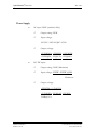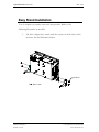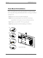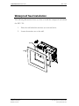
1
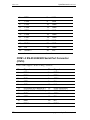
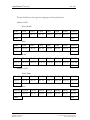
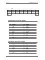
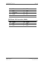
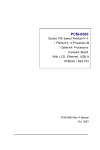
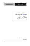
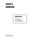
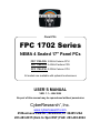
® Panel PCs FPC 1702 Series NEMA 4 Sealed 17" Panel PCs FPC 1702-C20: 2.0GHz Celeron CPU FPC 1702-P24: 2.4GHz Pentium CPU FPC 1702-P30: 3.0GHz Celeron CPU All models are available with optional touchscreens USER’S MANUAL VER. 1.1 • JAN 2004 No part of this manual may be reproduced without permission CyberResearch , Inc. ® www.cyberresearch.com 25 Business Park Dr., Branford, CT 06405 USA 203-483-8815 (9am to 5pm EST) FAX: 203-483-9024 ® CyberResearch Panel PCs FPC 1702 Series ©Copyright 2004 All Rights Reserved. January, 3 2004 The information in this document is subject to change without prior notice in order to improve reliability, design, and function and does not represent a commitment on the part of CyberResearch, Inc. In no event will CyberResearch, Inc. be liable for direct, indirect, special, incidental, or consequential damages arising out of the use of or inability to use the product or documentation, even if advised of the possibility of such damages. This document contains proprietary information protected by copyright. All rights are reserved. No part of this manual may be reproduced by any mechanical, electronic, or other means in any form without prior written permission of CyberResearch, Inc. Trademarks “CyberResearch,” and “FPC 1702 Series,” are trademarks of CyberResearch, Inc. Other product names mentioned herein are used for identification purposes only and may be trademarks and/or registered trademarks of their respective companies. • NOTICE • CyberResearch, Inc. does not authorize any CyberResearch product for use in life support systems, medical equipment, and/or medical devices without the written approval of the President of CyberResearch, Inc. Life support devices and systems are devices or systems which are intended for surgical implantation into the body, or to support or sustain life and whose failure to perform can be reasonably expected to result in injury. Other medical equipment includes devices used for monitoring, data acquisition, modification, or notification purposes in relation to life support, life sustaining, or vital statistic recording. CyberResearch products are not designed with the components required, are not subject to the testing required, and are not submitted to the certification required to ensure a level of reliability appropriate for the treatment and diagnosis of humans. CyberResearch, Inc. 25 Business Park Drive Branford, CT USA iii P: (203) 483-8815; F: (203) 483-9024 www.cyberresearch.com ® CyberResearch Panel PCs FPC 1702 Series Intentionally Blank iv ©Copyright 2004 CyberResearch, Inc. ® CyberResearch Panel PCs FPC 1702 Contents General Information.........................................................................................................1 Introduction..........................................................................................................2 Safety ...................................................................................................................5 FCC Safety...........................................................................................................7 Features ...............................................................................................................8 Specifications.......................................................................................................9 Dimensions ........................................................................................................15 Hardware Installation.....................................................................................................16 Safety Precautions..............................................................................................17 Locations of Connectors and Jumpers ...............................................................18 List of Jumpers...................................................................................................19 List of Connectors..............................................................................................20 Setting Jumpers..................................................................................................21 Clear CMOS.......................................................................................................22 Audio Out Select................................................................................................22 COM2 Ring/+5V/+12V Selection .....................................................................22 COM2 Rs-232/422/485 Select...........................................................................23 ATX Power Simulate AT Power .......................................................................23 IDE Connector ...................................................................................................24 Fan Connector....................................................................................................25 10/100Base-Tx Ethernet Connector...................................................................25 Option PME Connector......................................................................................25 Floppy Connector...............................................................................................26 LPT Port Connector ...........................................................................................26 Com1~3 RS-232/422/485 Serial Port Connector ..............................................27 PS2 Keyboard/Mouse Connector.......................................................................28 Digital I/O Port ..................................................................................................29 VGA Display Connector....................................................................................31 ATX Power Connector ......................................................................................31 ATX Power 12V Connector...............................................................................32 FDD & CD-ROM Installation ...........................................................................33 HDD Installation................................................................................................35 Easy Stand Installation.......................................................................................38 Panel Mount Kit Installation..............................................................................39 Waterproof Seal Installation ..............................................................................40 BIOS Installation ...........................................................................................................41 System Test and Initialization............................................................................42 Award BIOS Setup ............................................................................................43 Standard CMOS Features ..................................................................................46 Advanced BIOS Features...................................................................................47 Advanced Chipset Features................................................................................48 Integrated Peripherals ........................................................................................49 CyberResearch, Inc. 25 Business Park Drive Branford, CT USA v P: (203) 483-8815; F: (203) 483-9024 www.cyberresearch.com FPC 1702 ® CyberResearch Panel PCs Power Management Setup .................................................................................50 PnP/PCI Configuration ......................................................................................51 PC Health Status ................................................................................................52 Frequency/Voltage Control................................................................................53 Load FPC 1702 Defaults....................................................................................52 Set Supervisor/User Password ...........................................................................55 Save and Exit Setup ...........................................................................................56 Exit Without Saving...........................................................................................57 Limitations .........................................................................................................58 Driver Installation ..........................................................................................................59 Installation..........................................................................................................60 LAN Driver Installation.....................................................................................62 Card Reader Driver Installation .........................................................................63 Touchscreen Driver Installation.........................................................................63 Limitations .........................................................................................................63 vi ©Copyright 2004 CyberResearch, Inc. ® CyberResearch Panel PCs CyberResearch, Inc. 25 Business Park Drive Branford, CT USA FPC 1702 vii P: (203) 483-8815; F: (203) 483-9024 www.cyberresearch.com Chapter 1 General Information ® CyberResearch Panel PCs FPC 1702 Introduction FPC 1702 is one of the finest panel PCs in the CyberResearch product line. It features a PGA478 socket that can accommodate Pentium® 4 and Celeron® Processors, supporting FSB up to 400/533MHz. Best performance for multimedia solution CyberResearch’s FPC 1702 also supports DDR DRAM up to 1GB, 4X AGP bus, and 5.1 channel audio output, which means it supplies powerful multimedia functionality. This allows the FPC 1702 to be broadly implemented in many markets: Point of Sale, Point of Information (Kiosks) as well as gaming markets. Multi-Function Pentium4 Platform If you are looking for powerful multi-media applications, FPC 1702 is for you. The FPC 1702 integrates 17” color TFT LCD, Digital I/O, Audio and Ethernet function; additionally it also supports 5 USB2.0, mini PCI, and two PCI slots. With flexible expansion, you get easy access to solutions ranging from Modem, Storage, Sound Card, SCSI card, Audio/Video capture card, Wireless LAN module, to Bluetooth module. Especially for customers whose application is various or changing, the FPC 1702 reserves more than enough flexibility for future expansion. The FPC 1702 provides more CPU options for different applications. You can choose Pentium®4 processor up to 3.06G for high CyberResearch, Inc. 25 Business Park Drive Branford, CT USA 2 P: (203) 483-8815; F: (203) 483-9024 www.cyberresearch.com ® CyberResearch Panel PCs FPC 1702 performance application. Most of all Pentium®4 Level processors are suitable for FPC 1702. 3 ©Copyright 2004 CyberResearch, Inc. ® CyberResearch Panel PCs CyberResearch, Inc 25 Business Park Drive Branford, CT USA FPC 1702 4 P: (203) 483-8815; F: (203) 483-9024 www.cyberresearch.com ® CyberResearch Panel PCs FPC 1702 Safety 1. Read these safety instructions carefully. 2. Keep this user's manual for later reference. 3. Disconnect this equipment from any AC outlet before cleaning. Do not use liquid or spray detergents for cleaning. Use a damp cloth. 4. For pluggable equipment, the power outlet must be installed near the equipment and must be easily accessible. 5. Keep this equipment away from humidity. 6. Put this equipment on a reliable surface during installation. Dropping it or letting it fall could cause damage. 7. The openings on the enclosure are for air convection. Protect the equipment from overheating. DO NOT COVER THE OPENINGS. 8. Make sure the voltage of the power source is correct before connecting the equipment to the power outlet. 9. Position the power cord so that people cannot step on it. Do not place anything over the power cord. 10. All cautions and warnings on the equipment should be noted. 11. If the equipment is not used for a long time, disconnect it from the power source to avoid damage by transient over-voltage. 12. Never pour any liquid into an opening. This could cause fire or electrical shock. 13. Never open the equipment. For safety reasons, only qualified service personnel should open the equipment. 14. If any of the following situations arises, get the equipment checked by service personnel: a. The power cord or plug is damaged. b. Liquid has penetrated into the equipment. 5 ©Copyright 2004 CyberResearch, Inc. ® CyberResearch Panel PCs FPC 1702 c. The equipment has been exposed to moisture. d. The equipment does not work well, or you cannot get it to work according to the users manual. e. The equipment has been dropped and damaged. f. The equipment has obvious signs of breakage. 15. DO NOT LEAVE THIS EQUIPMENT IN AN UNCONTROLLED ENVIRONMENT WHERE THE STORAGE TEMPERATURE IS BELOW -20° C (-4° F) OR ABOVE 60° C (140° F). IT MAY DAMAGE THE EQUIPMENT. 16. External equipment intended for connection to signal input/output or other connectors, shall comply with relevant UL / IEC standard (e.g. UL 60950 for IT equipment and UL 2601-1 / IEC 60601 series for medical electrical equipment). In addition, all such combinations – systems – shall comply with the standard IEC 60601-1-1, Safety requirements for medical electrical systems. Equipment not complying with UL 2601-1 shall be kept outside the patient environment, as defined in the standard. CyberResearch, Inc. 25 Business Park Drive Branford, CT USA 6 P: (203) 483-8815; F: (203) 483-9024 www.cyberresearch.com ® CyberResearch Panel PCs FPC 1702 FCC Safety This device complies with Part 15 FCC Rules. Operation is subject to the following two conditions: (1) this device may not cause harmful interference, and (2) this device must accept any interference received including interference that may cause undesired operation. 7 ©Copyright 2004 CyberResearch, Inc. ® CyberResearch Panel PCs FPC 1702 Features CyberResearch, Inc. 25 Business Park Drive Branford, CT USA • 17” TFT SXGA (1280 x 1024) LCD • All-in-one SBC supports Socket 478 based Intel® Pentium®4 Processor • Supports Intel®Hyper-Threading Technology • Anti-vibration disk drive bay for HDD • Water-proof and anti-scratch IP-65 certified aluminum front panel with USB port certification • Two free PCI expansion slots • Digital I/O (8 in, 8 out as Default, up to 16 in or 16 out) • Resistive Touchscreen (Optional) 8 P: (203) 483-8815; F: (203) 483-9024 www.cyberresearch.com ® CyberResearch Panel PCs FPC 1702 Specifications System • Construction Heavy-duty steel chassis & IP-65 certified aluminum front panel (or optional stainless steel front panel) • CPU Socket 478 based Pentium® 4(.13μ) / Celeron® Processors up to 3.06GHz with FSB 400/533MHz, Hyper-Threading Technology supported • Memory 184 pin DIMM x 1, support DDR 200/266/333MHz up to 1GB • Display 17” SXGA color TFT LCD • LCD / CRT controller Intel® i845GV, AGP 4X • Network (LAN) Intel® 82562 10/100 Base-T Ethernet controller • 9 I/O Chipset 3 serial ports: 2 x RS-232, 1 x ©Copyright 2004 CyberResearch, Inc. ® CyberResearch Panel PCs FPC 1702 RS-232/422/485 (COM 4 is reserved for touch screen) 1 parallel port (supports ECP/EPP) 1 PS/2 mouse and keyboard port 1 VGA port Mic in, Line in, Line out, S/P DIF 5.1 channels audio port GPIO: 16 in or 16 out Storage Disk Drive Anti-vibration 2.5”HDD, Slim FDD and Slim CD-ROM USB ports 4 USB 2.0 ports on rear chassis 1 USB 2.0 port on front panel (Lockable by BIOS) Because of USB chipset limitation, front USB port and Card reader USB interface are linked together, when user “disable” front USB port (USB Port 3 controller ), the card reader must be forced to disable at same time. CyberResearch, Inc. 25 Business Park Drive Branford, CT USA Front Panel PMS 2965C (Dark Blue) Mounting Panel Mount, VESA 10 P: (203) 483-8815; F: (203) 483-9024 www.cyberresearch.com ® CyberResearch Panel PCs FPC 1702 75/100mm holes • Expansion slots 2 PCI slots 1 Mini PCI socket 6in1 card reader. Because of a driver bug, after successfully installing card reader drivers, two vanity disk drives appear: XD and Flash. Please ignore the two useless disk drives. Support CompactFlash® (Type I/II), Secure Digital, Multi Media Card, Memory Stick (PRO) and Smart Media • Power Supply Universal 250W switching power Supply with Active PFC • OS support Windows 98SE, Windows 2000, Windows XP • Dimension (W x H x D) 483 x 399 x 145mm (19” x 15.7” x 5.7”) • Carton Dimension (W x H x D) 620 x 522 x 351mm (24.4” x 20.6” x 13.8” ) • 11 Gross Weight 17.8KG (39.2 lbs) ©Copyright 2004 CyberResearch, Inc. ® CyberResearch Panel PCs FPC 1702 Power Supply • AC input 250W (standard offer): • Output rating: 250W • Input voltage: 100VAC~240VAC@47~63Hz • Output voltage: +3.3V@16A, + 5V@25A, +12V@13A, +5VSB@2A, [email protected], [email protected] • 24V DC input: • Output rating: 300W (Maximum) • Input voltage: 19VDC~36VDC@30A Maximum • Output voltage: +5V@25A, +12V@22A, +3.3V@20A, [email protected], -12V@1A, [email protected] CyberResearch, Inc. 25 Business Park Drive Branford, CT USA 12 P: (203) 483-8815; F: (203) 483-9024 www.cyberresearch.com ® CyberResearch Panel PCs FPC 1702 LCD Specifications Display type 17” color TFT LCD Max. Resolution 1280 x 1024 Max. Colors 256K Dot size (mm) 0.264 x 0.264 Luminance (cd/m2) 260 (TYP) 160° (H) Viewing angle 160° (V) 40,000 Back Light MTBF (Hrs) Touchscreen (Optional) • Type 8-wire, analog resistive • Resolution 2048 x 2048 • Light transmission Lifetime 1 million activations OS support Windows 98SE, Windows 2000, >75% Windows XP Environment Specifications • Operating temperature 0 ℃~50 ℃ (32~122℉) • Storage temperature -20℃~60 ℃ (-4~140℉) • Operating humidity 10 to 90% @35℃, non-condensing 13 ©Copyright 2004 CyberResearch, Inc. ® CyberResearch Panel PCs FPC 1702 Vibration 1G / 5~500Hz (Random / operation) Shock 15G peak acceleration (11 msec. duration) / operation CyberResearch, Inc. 25 Business Park Drive Branford, CT USA EMC CE/FCC Class B 14 P: (203) 483-8815; F: (203) 483-9024 www.cyberresearch.com ® CyberResearch Panel PCs FPC 1702 Dimension Unit : mm 137.00 36.00 130.00 120.60 323.70 399.00 130.00 8.00 246.00 364.00 483.00 465.00 25.00 55.00 17.50 446.00 402.00 15 150.00 7.00 25.00 150.00 FPC 1702 Cutout Size : 449 X 367 ©Copyright 2004 CyberResearch, Inc. Chapter 2 Hardware Installation Notice: The Quick Installation Guide is derived from Chapter 2 of user manual. For other chapters and further installation instruction s, please refer to the user manual CD -ROM that came with the product. ® CyberResearch Panel PCs FPC 1702 Safety Precautions Always completely disconnect the power cord from your board whenever you are working on it. Do not make connections while the power is on, because a sudden rush of power can damage sensitive electronic components. Always ground yourself to remove any static charge before touching the board. Modern electronic devices are very sensitive to static electric charges. Use a grounding wrist strap at all times. Place all electronic components on a static-dissipative surface or in a static-shielded bag when they are not in the chassis 17 ©Copyright 2004 CyberResearch, Inc. ® CyberResearch Panel PCs FPC 1702 Location of Connectors and Jumpers Component Side CyberResearch, Inc. 25 Business Park Drive Branford, CT USA 18 P: (203) 483-8815; F: (203) 483-9024 www.cyberresearch.com ® CyberResearch Panel PCs FPC 1702 List of Jumpers There are a number of jumpers in the board that allow you to configure your system to suit your application. The table below shows the function of each jumper in the board: Jumpers 19 Label Function JP1 Clear CMOS JP2 Audio Out Select JP3 COM2 Ring/+5V/+12V Selection JP4 COM2 RS-232/422/485 Selection JP5 COM2 RS-232/422/485 Selection JP6 ATX Power simulate AT Power JP7 LCD Voltage Selection ©Copyright 2004 CyberResearch, Inc. ® CyberResearch Panel PCs FPC 1702 List of Connectors There are a number of connectors in the board that allow you to configure your system to suit your application. The table below shows the function of each connector in the board: Connectors Label Function CN1 EIDE HDD Connector CN8,CN24 Fan Connector CN11 10/100Base-Tx Ethernet Connector CN12 Option PME Connector CN22 VGA Display Connector CN23 MINI PCI SLOT CN25 Front Panel CN27 ATX Power Connector CN28 ATX Power 12V Connector CyberResearch, Inc. 25 Business Park Drive Branford, CT USA 20 P: (203) 483-8815; F: (203) 483-9024 www.cyberresearch.com ® CyberResearch Panel PCs FPC 1702 Setting Jumpers You configure your card to match the needs of your application by setting jumpers. A jumper is the simplest kind of electric switch. It consists of two metal pins and a small metal clip (often protected by a plastic cover) that slides over the pins to connect them. To “close” a jumper you connect the pins with the clip. To “open” a jumper you remove the clip. Sometimes a jumper will have three pins, labeled 1, 2 and 3. In this case you would connect either pins 1 and 2 or 2 and 3. 3 1 2 Open Closed Closed 2-3 A pair of needle-nose pliers may be helpful when working with jumpers. If you have any doubts about the best hardware configuration for your application, contact your local distributor or sales representative before you make any change. Generally, you simply need a standard cable to make most connections. 21 ©Copyright 2004 CyberResearch, Inc. ® CyberResearch Panel PCs FPC 1702 Clear CMOS (JP1) Warning: To avoid damaging the computer, always turn off the power supply before setting “ Clear CMOS. ” Before turning on the power supply, set the jumper back to “Normal.” JP1 Function 1-2 Active (Default) 2-3 Clear Audio Out Select (JP2) JP2 Function 1-3, 2-4 W/O Amplifier (Default) 3-5, 4-6 W/ Amplifier COM2 Ring/+5V/+12V Selection (JP3) JP3 Function 1-2 +12V 3-4 +5V 5-6 Ring (Default) CyberResearch, Inc. 25 Business Park Drive Branford, CT USA 22 P: (203) 483-8815; F: (203) 483-9024 www.cyberresearch.com ® CyberResearch Panel PCs FPC 1702 COM2 RS-232/422/485 Select (JP4&JP5) JP4 JP5 Function 1-2, 4-5, 7-8, 10-11 1-2 RS-232 (Default) 2-3, 5-6, 8-9, 11-12 3-4 RS-422 2-3, 5-6, 8-9, 11-12 5-6 RS-485 ATX Power simulate AT Power (JP6) 23 JP6 Function 1-2 ON ATX Power Simulate AT Power 1-2 OFF ATX Standard (Default) ©Copyright 2004 CyberResearch, Inc. ® CyberResearch Panel PCs FPC 1702 IDE Connector (CN1) Pin Signal Pin Signal 1 IDE RESET 2 GND 3 DATA7 4 DATA8 5 DATA6 6 DATA9 7 DATA5 8 DATA10 9 DATA4 10 DATA11 11 DATA3 12 DATA12 13 DATA2 14 DATA13 15 DATA1 16 DATA14 17 DATA0 18 DATA15 19 GND 20 N.C 21 REQ 22 GND 23 IO WRITE 24 GND 25 IO READ 26 GND 27 IO READY 28 GND 29 DACK 30 GND 31 IRQ14 32 N.C 33 ADDR1 34 UDMA DETECT 35 ADDR0 36 ADDR2 37 CS#1 38 CS#3 39 LED 40 GND CyberResearch, Inc. 25 Business Park Drive Branford, CT USA 24 P: (203) 483-8815; F: (203) 483-9024 www.cyberresearch.com ® CyberResearch Panel PCs FPC 1702 Fan Connector (CN8&CN24) Pin Signal 1 GND 2 +5V 3 FAN SPEED SENSE 10/100Base-Tx Ethernet Connector (CN11) Pin Signal Pin Signal 1 TX+ 9 N.C 2 TX 10 N.C 3 RX+ 11 GND 4 N.C 12 GND 5 N.C 13 N.C 6 RX 14 N.C 7 N.C 15 N.C 8 N.C 16 N.C Option PME Connector (CN12) 25 Pin Signal Pin Signal 1 +5VSB 2 GND 3 #PME 4 SMB_DATA 5 SMB_CLK ©Copyright 2004 CyberResearch, Inc. ® CyberResearch Panel PCs FPC 1702 Floppy Connector (CN13) Pin Signal Pin Signal 1 GND 2 REDWC 3 GND 4 N.C 5 GND 6 DS1 7 GND 8 INDEX 9 GND 10 MOTOR A 11 GND 12 DRIVE SELECT B 13 GND 14 DRIVE SELECT A 15 GND 16 MOTOR B 17 GND 18 DIR 19 GND 20 STEP 21 GND 22 WRITE DATA 23 GND 24 WRITE GATE 25 GND 26 TRACK 27 GND 28 WRITE PROTECT 29 GND 30 READ DATA 31 GND 32 SIDE1 33 GND 34 DISK CHANGE LPT Port Connector (CN14) Pin Signal Pin Signal 1 STROBE 2 AFD 3 PTD0 4 ERROR CyberResearch, Inc. 25 Business Park Drive Branford, CT USA 26 P: (203) 483-8815; F: (203) 483-9024 www.cyberresearch.com ® CyberResearch Panel PCs FPC 1702 5 PTD1 6 INIT 7 PTD2 8 SLIN 9 PTD3 10 GND 11 PTD4 12 GND 13 PTD5 14 GND 15 PTD6 16 GND 17 PTD7 18 GND 19 ACK 20 GND 21 BUSY 22 GND 23 PE 24 GND 25 SELECT 26 N.C COM1~3 RS-232/422/485 Serial Port Connector (CN16) Only COM1 support “Wake on Ring” function. 27 Pin 1 Signa l DCD1 Pin 2 Signal DSR1 3 RXD1 4 RTS1 5 TXD1 6 CTS1 7 DTR1 8 RI1 9 GND 10 N.C 11 13 DCD2(422TXD-/485DATA-) RXD2(422TXD+/485DATA+) 12 14 DSR2 (422RXD+) RTS2 (422RXD-) 15 TXD2 16 CTS2 17 DTR2 18 RI2 19 GND 20 N.C 21 DCD3 22 DSR3 ©Copyright 2004 CyberResearch, Inc. ® CyberResearch Panel PCs FPC 1702 23 RXD3 24 RTS3 25 TXD3 26 CTS3 27 DTR3 28 RI3 29 GND 30 N.C 31 DCD4 32 DSR4 33 RXD4 34 RTS4 35 TXD4 36 CTS4 37 DTR4 38 RI4 39 GND 40 N.C PS2 Keyboard/Mouse Connector (CN17) Pin Signal 1 KB_DATA 2 KB_CLK 3 GND 4 +5V 5 MS_DATA 6 MS_CLK CyberResearch, Inc. 25 Business Park Drive Branford, CT USA 28 P: (203) 483-8815; F: (203) 483-9024 www.cyberresearch.com ® CyberResearch Panel PCs FPC 1702 Digital I/O Port 29 Pin Signal I/O Address Setting 1 Digital-IN / OUT 841H 2 Digital-IN / OUT 841H 3 Digital-IN / OUT 841H 4 Digital-IN / OUT 841H 5 GND 6 GND 7 Digital-IN / OUT 841H 8 Digital-IN / OUT 841H 9 Digital-IN / OUT 841H 10 Digital-IN / OUT 841H 11 GND 12 GND 13 Digital-IN / OUT 801H 14 Digital-IN / OUT 801H 15 Digital-IN / OUT 801H 16 Digital-IN / OUT 801H 17 GND 18 GND 19 Digital-IN / OUT 801H 20 Digital-IN / OUT 801H 21 Digital-IN / OUT 801H 22 Digital-IN / OUT 801H 23 +5V 24 +5V 25 +5V ©Copyright 2004 CyberResearch, Inc. ® CyberResearch Panel PCs FPC 1702 The pin definitions and registers mapping are illustrated below: Address: 841H 4 in / 4 out Pin1 Pin2 Pin3 Pin4 Pin7 Pin8 Pin9 Pin10 GPI 27 GPI 26 GPI 25 GPI 24 GPO 23 GPO 22 GPO 21 GPO 20 MSB LSB 8 in Pin1 Pin2 Pin3 Pin4 Pin7 Pin8 Pin9 Pin10 GPI 27 GPI 26 GPI 25 GPI 24 GPI 23 GPI 22 GPI 21 GPI 20 MSB LSB 8 out Pin1 Pin2 Pin3 Pin4 Pin7 Pin8 Pin9 Pin10 GPO 27 GPO 26 GPO 25 GPO 24 GPO 23 GPO 22 GPO 21 GPO 20 MSB LSB Address: 801H 4 in/ 4 out Pin13 Pin14 Pin15 Pin16 Pin19 Pin20 Pin21 Pin22 GPI 27 GPI 26 GPI 25 GPI 24 GPO 23 GPO 22 GPO 21 GPO 20 MSB LSB 8 in Pin13 Pin14 Pin15 Pin16 Pin19 Pin20 Pin21 Pin22 GPI 27 GPI 26 GPI 25 GPI 24 GPI 23 GPI 22 GPI 21 GPI 20 MSB CyberResearch, Inc. 25 Business Park Drive Branford, CT USA LSB 30 P: (203) 483-8815; F: (203) 483-9024 www.cyberresearch.com ® CyberResearch Panel PCs FPC 1702 8 out Pin13 Pin14 Pin15 Pin16 Pin19 Pin20 Pin21 Pin22 GPI 27 GPI 26 GPI 25 GPI 24 GPI 23 GPI 22 GPI 21 GPI 20 MSB LSB VGA Display Connector (CN22) Pin Signal Pin Signal 1 Red 9 GND 2 VCC 10 HSYNC 3 Green 11 GND 4 GND 12 VSYNC 5 Blue 13 GND 6 N.C 14 SCL 7 N.C 15 GND 8 SDA 16 N.C ATX Power Connector (CN27) 31 Pin Signal Pin Signal 1 +3.3V 11 +3.3V 2 +3.3V 12 -12V 3 GND 13 GND 4 +5V 14 PS_ON 5 GND 15 GND ©Copyright 2004 CyberResearch, Inc. ® CyberResearch Panel PCs FPC 1702 6 +5V 16 GND 7 GND 17 GND 8 POWER OK 18 -5V 9 +5VSB 19 +5V 10 +12V 20 +5V ATX Power 12V Connector (CN28) Pin Signal Pin Signal 1 GND 2 GND 3 +12V 4 +12V CyberResearch, Inc 25 Business Park Drive Branford, CT USA 32 P: (203) 483-8815; F: (203) 483-9024 www.cyberresearch.com ® CyberResearch Panel PCs FPC 1702 FDD & CD-ROM Installation We will guide through installing the FDD and CD-ROM together. Please see the details below: Step 1: Plug in FDD cable Step 2: Fasten the FDD and CD-ROM together with two brackets on the both sides symmetrically. 33 ©Copyright 2004 CyberResearch, Inc. ® CyberResearch Panel PCs FPC 1702 Step 3: Fasten the transferring bar with a pair of screws on the back of the CD-ROM. Step 4: Plug in CD-ROM Cable CyberResearch, Inc 25 Business Park Drive Branford, CT USA 34 P: (203) 483-8815; F: (203) 483-9024 www.cyberresearch.com ® CyberResearch Panel PCs FPC 1702 HDD Installation In the following, we will guide you through installing the HDD. Make sure all parts are provided before you start the installation. Step 1: Lock with the screws as the illustration shown. Step 2: Cover the screws with four pieces of anti-vibration rubbers 35 ©Copyright 2004 CyberResearch, Inc. ® CyberResearch Panel PCs FPC 1702 Step 3: Orient the two installation brackets as shown . below. Step 4: Install the HDD in the bracket as shown below. CyberResearch, Inc 25 Business Park Drive Branford, CT USA 36 P: (203) 483-8815; F: (203) 483-9024 www.cyberresearch.com ® CyberResearch Panel PCs FPC 1702 Step 5: Install the other half of the bracket, then tighten the screws. Step 6: Install the HDD module into the FPC 1702 chassis and plug in the cable. Fix the HDD module with the screws Plug the cable in 37 ©Copyright 2004 CyberResearch, Inc. ® CyberResearch Panel PCs FPC 1702 Easy Stand Installation Two L-shaped easy stands come with the product. Refer to the following illustration to install it. 1. Fix the L-shaped easy stands with the screws on both sides of the monitor. See the illustration below: *4-M4 Screw CyberResearch, Inc 25 Business Park Drive Branford, CT USA 38 P: (203) 483-8815; F: (203) 483-9024 www.cyberresearch.com ® CyberResearch Panel PCs FPC 1702 Panel Mount Kit Installation Some of the hardware that comes withe the product is for panel mounting. See the steps below along with the illustration. Refer to next page if installation waterproof seal. Step 1: Insert the screw into the panel-mounting clip. Step 2: Insert the screw & clip into one of the slots on the chassis and pull back to lock in place (as shown in illustrations below). Step 3: Tighten screw until FPC 1702 is snug with panel. Step 4: Repeat procedure with each remaining set of hardware. 1 2 3 4 Panel Mounting 39 ©Copyright 2004 CyberResearch, Inc. ® CyberResearch Panel PCs FPC 1702 Waterproof Seal Installation The following illustration shows you how to install the waterproof seal behind the FPC 1702. 1. Place the seal behind the monitor set as shown below. 2. Locate the monitor set on the wall. Sponge Wall CyberResearch, Inc 25 Business Park Drive Branford, CT USA 40 P: (203) 483-8815; F: (203) 483-9024 www.cyberresearch.com Chapter 3 BIOS Installation ® CyberResearch Panel PCs FPC 1702 System test and initialization These routines test and initialize board hardware. If the routines encounter an error during the tests, you will either hear a few short beeps or see an error message on the screen. There are two kinds of errors: fatal and non fatal. The system can usually continue the boot up sequence with non-fatal errors. Non-fatal error messages usually appear on the screen along with the following instructions: Press <F1> to RESUME Write down the message and press the F1 key to continue the boot up sequence. System configuration verification These routines check the current system configuration against the values stored in the CMOS memory. If they do not match, the program outputs an error message. You will then need to run the BIOS setup program to set the configuration information in memory. There are three situations in which you will need to change the CMOS settings: 1. You are starting your system for the first time 2. You have changed the hardware attached to your system 3. The CMOS memory has lost power and the configuration CyberResearch, Inc 25 Business Park Drive Branford, CT USA 42 P: (203) 483-8815; F: (203) 483-9024 www.cyberresearch.com ® CyberResearch Panel PCs FPC 1702 information has been erased. The FPC 1702 CMOS memory has an integral lithium battery backup for data retention. However, you will need to replace the complete unit when it finally runs down. Award BIOS Setup Awards BIOS ROM has a built-in Setup program that allows users to modify the basic system configuration. This type of information is stored in battery-backed CMOS RAM so that it retains the Setup information when the power is turned off. Entering setup Power on the computer and press <Del> immediately. This will allow you to enter Setup. 43 ©Copyright 2004 CyberResearch, Inc. ® CyberResearch Panel PCs FPC 1702 Standard CMOS Features Use this menu for basic system configuration. (Date, time, IDE, etc.) Advanced BIOS Features Use this menu to set the advanced features available on your system. Advanced Chipset Features Use this menu to change the values in the chipset registers and optimize your system performance. Integrated Peripherals Use this menu to specify your settings for integrated peripherals. (Primary slave, secondary slave, keyboard, mouse etc.) Power Management Setup Use this menu to specify your settings for power management. (HDD power down, power on by ring, KB wake up, etc.) PnP/PCI Configurations This entry appears if your system supports PnP/PCI. PC Health Status This menu allows you to set the shutdown temperature for your system. Frequency/Voltage Control Use this menu to specify your settings for frequency/ voltage control. Load Defaults Use this menu to load the BIOS default values for the minimal/stable performance for your system to operate. CyberResearch, Inc 25 Business Park Drive Branford, CT USA 44 P: (203) 483-8815; F: (203) 483-9024 www.cyberresearch.com ® CyberResearch Panel PCs FPC 1702 Set Supervisor/User Password Use this menu to set Supervisor/User Passwords. Save and Exit Setup Save CMOS value changes to CMOS and exit setup. Exit Without Saving Abandon all CMOS value changes and exit setup. 45 ©Copyright 2004 CyberResearch, Inc. ® CyberResearch Panel PCs FPC 1702 Standard CMOS Features When you choose the Standard CMOS Features option from the INITIAL SETUP SCREEN menu, the screen shown below is displayed. This standard Setup Menu allows users to configure system components such as date, time, hard disk drive, floppy drive and display. Once a field is highlighted, on-line help information is displayed in the right box of the Menu screen. CyberResearch, Inc 25 Business Park Drive Branford, CT USA 46 P: (203) 483-8815; F: (203) 483-9024 www.cyberresearch.com ® CyberResearch Panel PCs FPC 1702 Advanced BIOS Features By choosing the Advanced BIOS Features option from the INITIAL SETUP SCREEN menu, the screen below is displayed. This sample screen contains the manufacturer’ s default values. 47 ©Copyright 2004 CyberResearch, Inc. ® CyberResearch Panel PCs FPC 1702 Advanced Chipset Features By choosing the Advanced Chipset Features option from the INITIAL SETUP SCREEN menu, the screen below is displayed. This sample screen contains the manufacturer’ s default values. Attention: The LCD signal may be turned off automatically after the VGA driver is installed, please press “Ctrl + Alt + F3” to enable LCD signal again. CyberResearch, Inc 25 Business Park Drive Branford, CT USA 48 P: (203) 483-8815; F: (203) 483-9024 www.cyberresearch.com ® CyberResearch Panel PCs FPC 1702 Integrated Peripherals By choosing the Integrated Peripherals from the INITIAL SETUP SCREEN menu, the screen below is displayed. This sample screen contains the manufacturer’ s default values. 49 ©Copyright 2004 CyberResearch, Inc. ® CyberResearch Panel PCs FPC 1702 Power management Setup By choosing the Power Management Setup from the INITIAL SETUP SCREEN menu, the screen below is displayed. This sample screen contains the manufacturer’ s default values. CyberResearch, Inc 25 Business Park Drive Branford, CT USA 50 P: (203) 483-8815; F: (203) 483-9024 www.cyberresearch.com ® CyberResearch Panel PCs FPC 1702 PnP/PCI configuration By choosing the PnP/PCI configurations from the Initial Setup Screen menu, the screen below is displayed. This sample screen contains the manufacturer’ s default values. 51 ©Copyright 2004 CyberResearch, Inc. ® CyberResearch Panel PCs FPC 1702 PC Health Status By choosing the PC Health Status from the Initial Setup Screen menu, the screen below is displayed. This sample screen contains the manufacturer’ s default values. CyberResearch, Inc 25 Business Park Drive Branford, CT USA 52 P: (203) 483-8815; F: (203) 483-9024 www.cyberresearch.com ® CyberResearch Panel PCs FPC 1702 Frequency/Voltage control By choosing the Frequency/Voltage Control from the Initial Setup Screen menu, the screen below is displayed. This sample screen contains the manufacturer’ s default values. 53 ©Copyright 2004 CyberResearch, Inc. ® CyberResearch Panel PCs FPC 1702 Load FPC 1702 Defaults When you press <Enter> on this item you get a confirmation dialog box with a message similar to: Load Defaults (Y/N)? Pressing "Y" loads the BIOS default values for the most stable, minimal performance system operations. CyberResearch, Inc 25 Business Park Drive Branford, CT USA 54 P: (203) 483-8815; F: (203) 483-9024 www.cyberresearch.com ® CyberResearch Panel PCs FPC 1702 Set Supervisor/User Password You can set either SUPERVISOR or USER PASSWORD, or both of them. The difference between the two is that the supervisor password allows unrestricted access to enter and change the options of the setup menus, while the user password only allows entry to the program, but not modify options. To abort the process at any time, press Esc. In the Security Option item in the BIOS Features Setup screen, select System or Setup: System Enter a password each time the system boots and when ever you enter Setup. Setup Enter a password whenever you enter Setup. NOTE: To clear the password, simply press Enter when asked to enter a password. Then the password function is disabled. 55 ©Copyright 2004 CyberResearch, Inc. ® CyberResearch Panel PCs FPC 1702 Save & Exit Setup If you select this option and press <Enter>, the values entered in the setup utilities will be recorded in the chipset’ s CMOS memory. The microprocessor will check this every time you turn on your system and compare this to what it finds as it checks the system. This record is required for the system to operate. CyberResearch, Inc 25 Business Park Drive Branford, CT USA 56 P: (203) 483-8815; F: (203) 483-9024 www.cyberresearch.com ® CyberResearch Panel PCs FPC 1702 Exit without saving Selecting this option and pressing <Enter> allows you to exit the Setup program without recording any new value or changing old one. 57 ©Copyright 2004 CyberResearch, Inc. ® CyberResearch Panel PCs FPC 1702 Limitations 1. Due to Intel chipset limitation, when CMOS was set up to “LCD + CRT”, the LCD display will not support full-screen appearance. 2. Because of USB chipset limitation, front USB port and Card reader USB interface are linked together, when user “disable” front USB port ( USB Port 3 controller), the card reader must be forced to disable at same time. CyberResearch, Inc 25 Business Park Drive Branford, CT USA 58 P: (203) 483-8815; F: (203) 483-9024 www.cyberresearch.com Chapter 4 Driver Installation ® CyberResearch Panel PCs Note: FPC 1702 If you are unsure about which drivers to install, click on X: > Driver > System > FPC 1702. All drivers for the FPC 1702 are listed here. Each folder is labeled by step to indicate installation order. (X is CD ROM with Driver CD running.) Please follow the sequence below to install the drivers: Step 1 – Install Intel INF Update For Windows 9x-XP Driver Step 2 – Install Intel 845G Graphic Driver Step 3 – Install Intel Application Accelerator for Windows 9x-XP Driver Step 4 – Install Intel LAN Driver V6.4 Step 5 – Install Realtek AC97 codec Driver Step 6 – Install Card Reader Driver Step 7 – Install Touch screen Driver USB 2.0 Drivers are available for download using Windows Update for both Windows XP and Windows 2000. For additional information regarding USB 2.0 support in Windows XP and Windows 2000, please visit www.microsoft.com/hwdev/usb/. For installation procedures of each driver, you may see the details in the following. Installation Applicable for Windows 98SE / 2000 / XP 1. From the CD-ROM, select the desired component Driver folder, and then select the desired Operation System folder to double click on the Setup.exe icon. A driver installation screen will appear. Notice: 1. Take VGA driver installation under Windows 98 for example, choose the corresponding folder depending on your OS 2. When installing the VGA driver under Windows 98, the CyberResearch, Inc 25 Business Park Drive Branford, CT USA 60 P: (203) 483-8815; F: (203) 483-9024 www.cyberresearch.com ® CyberResearch Panel PCs FPC 1702 system will ask you to reboot the computer. During the installation process, it appears as a pop-up window: 2. 3. Press ok. Another window appears: 4. Change the path to the installation folder and search for the two files named as ikch8xx.cat and isb8xx.cat. A driver installation screen will appear, please follow the onscreen instructions to install the driver in sequence and click on the Next button. Notice: In some cases the system will ask you to insert 61 ©Copyright 2004 CyberResearch, Inc. ® CyberResearch Panel PCs FPC 1702 Windows 98 CD ROM and key in its path. Then click on the OK button to key in path. 3. Click on the Finish button to finish installation process. And allow the system to reboot. 4. The LCD signal may be turned off automatically after the VGA driver is installed, please press "Ctrl+Alt+F3" to enable LCD signal again. LAN Driver Installation We strongly recommend that you shall not install LAN driver by clicking on Autorun Exe. Please follow the steps in order to finish the process of installation. 1. Click on Start button → Settings → Control Panel → System 2. Select Device Manager under the Hardware category. 3. Double click on the Ethernet controller and select update Driver button under the Driver category. 4. Click Next twice and tick the Specify a location option. 5. Click Next and choose a route where you want place the folders on before you click on open. 6. Click Next → Yes → Finish and the window will show you how to finish the installation process. CyberResearch, Inc. Inc 25 Business Park Drive Branford, CT USA 62 P: (203) 483-8815; F: (203) 483-9024 www.cyberresearch.com ® CyberResearch Panel PCs FPC 1702 Card Reader Driver Installation 1. Enter X: > Driver > System > FPC 1x02 → Step 6 Card Readers Driver folder. 2. Double click on the Setup exe. file. 3. Language setting: Choose the highlighted item below to operate your system in English. 4. Follow the instruction that the window will show to finish the installation. Touch screen Driver Installation 1. Enter X: > Driver > System > FPC 1x02 → Step 7 Touch screen Driver folder. 2. Double click on the Setup exe. file. Limitations 63 • For the sake of the bugs of card reader driver, two useless disk drives will appear: XD and Flash after installing drivers successfully. Please ignore the two useless disk drives. • The limitations you may need to notice when you start to install the driver. For the sake of USB4 and USB5 community of linkage, the card reader must be forced to disable when the users “disable” front USB port. ©Copyright 2004 CyberResearch, Inc. ® CyberResearch Panel PCs FPC 1702 Series Product Service Diagnosis and Debug CyberResearch, Inc. maintains technical support lines staffed by experienced Applications Engineers and Technicians. There is no charge to call and we will return your call promptly if it is received while our lines are busy. Most problems encountered with data acquisition products can be solved over the phone. Signal connections and programming are the two most common sources of difficulty. CyberResearch support personnel can help you solve these problems, especially if you are prepared for the call. To ensure your call’s overall success and expediency: 1) 2) 3) 4) 5) 6) Have the phone close to the PC so you can conveniently and quickly take action that the Applications Engineer might suggest. Be prepared to open your PC, remove boards, report back-switch or jumper settings, and possibly change settings before reinstalling the modules. Have a volt meter handy to take measurements of the signals you are trying to measure as well as the signals on the board, module, or power supply. Isolate problem areas that are not working as you expected. Have the source code to the program you are having trouble with available so that preceding and prerequisite modes can be referenced and discussed. Have the manual at hand. Also have the product’s utility disks and any other relevant disks nearby so programs and version numbers can be checked. Preparation will facilitate the diagnosis procedure, save you time, and avoid repeated calls. Here are a few preliminary actions you can take before you call which may solve some of the more common problems: 1) 2) 3) 4) Check the PC-bus power and any power supply signals. Check the voltage level of the signal between SIGNAL HIGH and SIGNAL LOW, or SIGNAL+ and SIGNAL– . It CANNOT exceed the full scale range of the board. Check the other boards in your PC or modules on the network for address and interrupt conflicts. Refer to the example programs as a baseline for comparing code. CyberResearch, Inc. 25 Business Park Drive Branford, CT USA 65 P: (203) 483-8815; F: (203) 483-9024 www.cyberresearch.com ® CyberResearch Panel PCs FPC 1702 Series Intentionally Blank 66 ©Copyright 2004 CyberResearch, Inc. ® CyberResearch Panel PCs FPC 1702 Series Warranty Notice CyberResearch, Inc. warrants that this equipment as furnished will be free from defects in material and workmanship for a period of one year from the confirmed date of purchase by the original buyer and that upon written notice of any such defect, CyberResearch, Inc. will, at its option, repair or replace the defective item under the terms of this warranty, subject to the provisions and specific exclusions listed herein. This warranty shall not apply to equipment that has been previously repaired or altered outside our plant in any way which may, in the judgment of the manufacturer, affect its reliability. Nor will it apply if the equipment has been used in a manner exceeding or inconsistent with its specifications or if the serial number has been removed. CyberResearch, Inc. does not assume any liability for consequential damages as a result from our products uses, and in any event our liability shall not exceed the original selling price of the equipment. The equipment warranty shall constitute the sole and exclusive remedy of any Buyer of Seller equipment and the sole and exclusive liability of the Seller, its successors or assigns, in connection with equipment purchased and in lieu of all other warranties expressed implied or statutory, including, but not limited to, any implied warranty of merchant ability or fitness and all other obligations or liabilities of seller, its successors or assigns. The equipment must be returned postage prepaid. Package it securely and insure it. You will be charged for parts and labor if the warranty period has expired. Returns and RMAs If a CyberResearch product has been diagnosed as being non-functional, is visibly damaged, or must be returned for any other reason, please call for an assigned RMA number. The RMA number is a key piece of information that lets us track and process returned merchandise with the fastest possible turnaround time. PLEASE CALL FOR AN RMA NUMBER! Packages returned without an RMA number will be refused! In most cases, a returned package will be refused at the receiving dock if its contents are not known. The RMA number allows us to reference the history of returned products and determine if they are meeting your application’s requirements. When you call customer service for your RMA number, you will be asked to provide information about the product you are returning, your address, and a contact person at your organization. Please make sure that the RMA number is prominently displayed on the outside of the box. • Thank You • CyberResearch, Inc. 25 Business Park Drive Branford, CT USA 67 P: (203) 483-8815; F: (203) 483-9024 www.cyberresearch.com ® CyberResearch Panel PCs FPC 1702 Series Intentionally Blank 68 ©Copyright 2004 CyberResearch, Inc. CyberResearch, Inc. 25 Business Park Drive Branford, CT 06405 USA P: (203) 483-8815; F: (203) 483-9024 www.cyberresearch.com