1
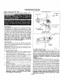
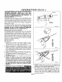
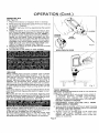
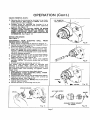
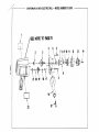
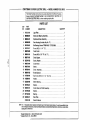
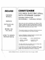
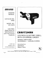
OWNERS
MANUAL
CATALOG NO.
10420
MODEL NO.
315.10419
CAUTION:
Read Rules for
Safe Operation
and Instructions
Carefully
CRAFTSMAN
3/8 INCH ELECTRIC DRILL
WITH STORAGE CADDY
DOUBLE INSULATED
REVERSIBLE - VARIABLE SPEED
SAVE THIS
MANUAL FOR
FUTURE REFERENCE
Introduction
Operation
Repair Parts
Designed exclusively for ani sold 'only by
SEARS, ROEBUCK AND CO., Dept. 698/7~lA, Sears Tower, ChicaQo, IL 60684
PA!NlEO IN U.S.A
FULL ONE YEAR WARRANTY ON CRAFTSMAN ELECTRIC DRILL
If this Craftsman Electric Drill fails to give complete satisfaction within one year from the date of
purchase, RETURN IT TO THE NEAREST SEARS STORE THROUGHOUT THE UNITED STATES and
Sears will repair it, free of charge.
If this electric drill is used for commercial or rental purposes this warranty applies for only 90 days
from the date of purchase.
This warranty gives you specific legal rights, and you may also have other rights which vary from
state to state.
SEARS, ROEBUCK AND CO.
DEPT. 6981731 A
SEARS TOWER
CHICAGO, IL 60684
INTRODUCTION
DOUBLE INSULATION is a concept in safety, in electric
power tools, which eliminates the need for the usual
three wire grounded power cord and grounded supply
system. Wherever there is electric current in the tool
there are two complete sets of insulation to protect the
user. All exposed metal parts are isolated from the internal metal motor components with protecting insulation.
IMPORTANT - servicing of a tool with double insulation requires extreme care and knowledge of the system
and should be performed only by a qualified service
technician. For service we suggest you return the tool
to your nearest Sears Store for repair. Always use
original factory replacement parts when servicing.
RULES FOR SAFE OPERATION
~WARNING DO NOT ATTEMPT TO OPERATE THIS TOOL UNTIL YOU HAVE READ THOROUGHLY AND
UNDERSTANO COMPlETEl Y ALL INSTRUCTIONS. SAFETY RULES. ETC CONTAINED IN THIS MANUAL
F AlLURE TO COMPLY CAN RESULT IN ACCIDENTS INVOLVING FIRE ELECTRIC SHOCK OR SERIOUS
PERSONAL INJURY SAVE OWNERS MANUAL AND REVIEW FREOUENTL Y FOR CONTINUING SAFE
OPERATION AND INSTRUCTING POSSIBLE THIRD PARTY USER
READ ALL INSTRUCTIONS
1. KNOW YOUR POWER TOOL -
Read owner's manual carefully. Learn its applications and limitations as well as the specific potential hazards related to
this tool.
2. GUARD AGAINST ELECTRICAL SHOCK BY PREVENTING BODY CONTACT
WITH GROUNDED SURFACES. For example: Pipes, radiators, ranges, refrigerator enclosures.
3. KEEP GUARDS IN PLACE and in working order.
4. KEEP WORK AREA CLEAN. Cluttered areas and benches invite accidents.
5. AVOID DANGEROUS ENVIRONMENT. Don't use power tool in damp or wet
loca1ions or expose to rain. Keep work area well lit.
6. KEEP CHILDREN AWAY. All visitors should wear safety glasses and
be kept a safe distance from work area. Do not let visitors contact tool or
extension cord.
7. STORE IDLE TOOLS. When not in use, tools should be stored in a dry, high or
locked-up place - out of the reach of children.
8. DON'T FORCE TOOL. It will do the job better and safer at the rate for which it
was designed.
9. USERIGHT TOOL. Don't force small tool or attachment to do the job of a heavy
duty tool. Don't use tool for purpose not intended - for example - Don't use
a circular saw for cutting tree limbs or logs.
10. WEAR PROPER APPAREL. No loose clothing or jewelry to get caught in moving
parts. Rubber gloves and footwear are recommended when working outdoors.
Also, wear protective hair covering to contain long hair.
11. WEAR SAFETY GLASSES with all tools. Also wear a face shield or dust mask if
cutting operation is dusty.
Page 2
RULES FOR SAFE OPERATION (Continued)
12. DON'T ABUSE CORD. Never carry tool by cord or yank it to disconnect from
receptacle. Keep cord from heat, oil, and sharp edges.
13. SECURE WORK. Use clamps or a vise to hold work. Both hands are needed to
operate the tool.
14. DON'T OVERREACH. Keep proper footing and balance at all times. Do not use
on a ladder or unstable support.
15. MAINTAIN TOOLS WITH CARE. Keep tools sharp at all times, and clean for best
and safest performance. Follow instructions for lubricating and changing ac·
cessories.
16. DISCONNECT TOOLS. When not in use, before servicing, or when changing at·
tachments, blades, bits, cutlers, etc., all tools should be disconnected from
power supply.
17. REMOVE ADJUSTING KEYS AND WRENCHES. Form habit of checking to see
that keys and adjusting wrenches are removed from tool before turning it on.
18. AVOID ACCIDENTAL STARTING. Don't carry plugged·in tools with finger on
switch. Be sure switch is off when plugging in.
19 OUTDOOR USE EXTENSION CORDS. When tool is used outdoors, use only
extension cords suitable for use outdoors. Outdoor approved cords are marked
with the suffix W-A, for example - SJTW-A or SJOW-A.
20. KEEP BITS CLEAN AND SHARP. Sharp bits minimize stalling and kickback.
21. KEEP HANDS AWAY FROM DRILLING AREA. Keep hands away from bits. Do
not reach underneath work while bit is rotating. Do not attempt to remove
material while bit is rotating.
22. NEVER USE IN AN EXPLOSIVE ATMOSPHERE. Normal sparking of the motor
could ignite fumes.
23. INSPECT TOOL CORDS PERIODICALLY and if damaged, have repaired at your
nearest Sears Repair Center.
24 INSPECT EXTENSION CORDS PERIODICALLY and replace if damaged.
25 KEEP HANDLES DRY, CLEAN, AND FREE FROM OIL AND GREASE. Always
use a clean cloth when cleaning. Never use brake fluids, gasoline, petroleumbased products, or any strong solvents to clean your tool.
26. STAY ALERT. Watch what you are doing and use common sense. Do not operate tool when you are tired. Do not rUSh.
27. CHECK DAMAGED PARTS. Before further use of the tool, a guard or
other part that is damaged should be carefully checked to determine that it will
operate properly and perform its intended function. Check for alignment of moving parts, binding of moving parts, breakage of parts, mounting, and any other
conditions that may affect its operation. A guard or other part that is damaged
should be properly repaired or replaced by an authorized service center.
28. DO NOT USE TOOL IF SWITCH DOES NOT TURN IT ON AND OFF. Have defect·
ive switches replaced by an authorized service center.
29. DRILLING INTO ELECTRICAL WIRING IN WALLS CAN CAUSE DRILL BIT AND
CHUCK TO BECOME ELECTRICALLY LIVE. Do not touch the chuck or metal
housing when drilling into a wall; grasp only the insulated handle(s) provided on
the tool.
3D. Inspect for and remove all nails from lumber before drilling.
31. DRUGS, ALCOHOL, MEDICATION. Do not operate tool while under the influence of drugs, alcohol, or any medication.
32. WEAR HEARING PROTECTION DURING EXTENDED PERIODS OF OPERATION.
33. SAVE THESE INSTRUCTIONS. Refer to them frequently and use them to
instruct third party users. If you loan someone this tool, loan them these instructions also.
Page 3
OPERATION
...WARNING ALWAYS WEAR SAFETY GLASSES
OR EYESHIELDS WHEN OPERATING YOUR
ELECTRIC DRILL FAILURE TO DO SO COULD
RESULT IN OBJECTS BEING THROWN INTO
YOUR EYES RESULTING IN POSSIBLE SERIOUS
INJURY
REVERSIBLE
Your electric drill has the feature of being reversible.
The direction of rotation is controlled by a lever
located above the trigger switch. See Figure 1. With
drill held in normal operating position, the direction
of rotation le,er should be positioned to the right of
the switch for drilling. The drill direction is reversed
when the le,er is to the left of the switch. TH E
DESIGN OF THE SWITCH WILL NOT PERMIT
CHANGING DIRECTION OF ROTATION WHILE
DRILL IS RUNNING. RELEASE THE SWITCH TRIG·
GER AND ALLOW THE DRILL TO STOP BEFORE
CHANGING ITS DIRECTION. NOTE: THE TOOL
WILL NOT RUN UNLESS THE SWITCH LEVER IS
PUSHED FULLY TO LEFT OR RIGHT.
AUTO·CHUCK
Your electric drill also has the feature of an auto·
chuck. As the name implies, you can now install and
remove bits ",ithout the need for a chuck key to
tighten the chuck jaws.
We suggest that you practice with the auto·chuck
feature of your electric drill before installing a drill
bit and drilling holes, etc.
TO CLOSE CHUCK JAWS
1. Depress and release the switch trigger of your
drill to be sure it is in the "off" position before
connecting to power supply source.
2. Check the direction of rotation lever for correct
setting (forward or reverse). See Figure 1. Move
direction of rotation lever to "forward".
3. Plug your electric drill into power supply source.
4. Point the drill away from your body as shown in
Figure 2. Also, once you begin installing bits
(see page 5), raise the front of your drill slightly
to keep the drill bits from falling out of the chuck
jaws.
5. SLOWLY start your drill by gradually depressing
the switch trigger.
6. Grasp the sleeve of your drill's auto chuck as
shown in Figure 2 and pUll it toward the gear
housing. Note that the chuck jaws are closing.
When it appears that the chuck jaws have closed
to a point where the opening is sl ightly larger
than the drill bit you intend to use, release the
auto·chuck sleeve. TO PREVENT POSSIBLE
DAMAGE, DO NOT ALLOW THE CHUCK JAWS
TO CLOSEON THEMSELVES.
TRIGGER
.....FORWARD
REVERSE ~
VARIABLE SPEED
CONTROL SELECTOR
~_______
Fig.
Fig. 2.
TO OPEN CHUCK JAWS
To open the chuck jaws, move the direction of rota·
tion lever to "reverse" and repeat procedures 3 thru 6
under "To Close Chuck Jaws". Note that the chuck
jaws are opening. When they have released your drill
bit, you should release the auto-chuck sleeve. TO
PREVENT POSSIBLE DAMAGE, DO NOT ALLOW
THE CHUCK JAWS TO OPEN ALL THE WAY AND
RACHET.
VARIABLE SPEED
Your electric drill has a variable speed control selec.
tor designed to allow operator control of speed and
torque limits. See Figure 1. To increase the speed
and torque of your electric drill, hold your drill in nor.
mal operating position and turn the variable speed
control selector counterclockwise. Turn clockwise
to decrease the speed and torque of your electric
drill. If you desire to lock the switch on at a given
speed, pull the trigger of the switCh, push in the lock
butlon located on the side of the handle, then while
holding the lock button pushed in release the trig·
ger. Next, adjust the variable speed control selector
until the desired speed is reached. NOTE: IF THE
VARIABLE SPEED CONTROL SELECTOR IS FULLY
TURNED IN THE CLOCKWISE DIRECTION, YOUR
DRILL MAY NOT RUN.
Page 4
OPERATION (Cant.)
IF YOU DESIRE NOT TO USE THE VARIABLE SPEED
CONTROL SELECTOR, TURN IT IN THE FULL
COUNTERCLOCKWISE DIRECTION. THIS WILL
ALLOW THE SPEED OF YOUR ELECTRIC DRILL TO
BE FULLY CONTROLLED BY THE AMOUNT OF
SWITCH TRIGGER DEPRESSION.
LOCK·ON SWITCH
The switch of your electric drill is equipped with a
"Iock·on" feature for added utility and convenience
when drilling in soft woods or soft metals. To lock·
on, simply depress the trigger of the switch, push in
the lock butlon localed on the side of the handle,
then while holding the lock button pushed in,
release the trigger.
To release the lock, depress the trigger and release
it. Do not lock the trigger on heavy jobs where the
drill may have to be stopped quickly. BE SURE THE
TRIGGER IS NOT IN THE "LOCK·ON" POSITION
BEFORE CONNECTING TO POWER SUPPLY.
SLEEVE
Fig. 3
INSTALLING AUXILIARY HANDLE
An auxiliary handle is packed with your drill for ease
of operation and to help prevent loss of control. It
may be installed on either side of your drill. To in·
stall, insert the hex head cap screw through the han·
die. Using a screwdriver, push on the head of the cap
screw in order to seat it into the molded portion of
the handle. Next, start the threads into the threaded
hole in the gear housing by turning the handle
clockwise. Tighten securely.
INSTALLING BITS
See Figure 3.
1. Depress and release the switch trigger of your
drill to be sure It is in the "Off" position before
connecting it to the power supply source.
2. Check the direction of rotation lever for correct
setting (forward or reverse). See Figure 1. The
direction of rotalion lever on the switch should be
in its maximum forward position when installing
bits. It should be in its maximum reverse position
when removing bits.
3. Plug your electric drill into power supply source.
4. Raise your drill slightly and point it away from
your body as shown in Figures 2 and 3.
5. SLOWLY start your drill by gradually depressing
the switch trigger.
6. Grasp the sleeve of your drill's auto chuck as
shown in Figure 3 and pull it toward the gear
housing.IThis engages the auto·chuck). Note that
the chuck jaws are closing. When it appears that
the jaws have ciosed to a point where the open·
ing Is slightly larger than the bit size you intend
to use, release the auto·chuck sleeve. DO NOT
ALLOW THE CHUCK JAWS TO CLOSE ON THEM·
SELVES.
7. Insert your drill bit into chuck the full len
the jaws as shown in FI ure 4.
.
•
•••
.
•
••
•
R
I
G
H
T
Fig. 4
Fig.5
8. Tighten chuck jaws on drill bit by grasping the
sleeve, pulling it toward the housing, and slowly
starting your drill as described above.
9. Full speed is needed to lighten chuck jaws on
bit. The clutch is engaged when you hear a
racheting noise. It takes approximately one se·
cond of this racheting to securely tighten the
drill bit in the chuck jaws. NOTE: II drill bit slips
or is still not tight in the chuck jaws, repeat the
above procedure.
Page, 5
OPERATION (Cont.)
REMOVING BITS
See Figure 6.
1. Place the direction of rotation lever in reverse.
2. Point yourdrill downward away from your body as
as shown in Figure 6.
3. SLOWLY start your drill by depressing the switch
trigger.
4. Grasp the sleeve of your drill's Auto-Chuck and
pull toward the gear housing. Full speed is need·
ed to loosen chuck jaws from drill bit. NOTE: If
bit fails to loosen, repeat this procedure and pull
harder on the sleeve. After prolonged use, the
drill chuck may be so tight that the bit cannot be
removed by this procedure. If this occurs place
the edge 01 the chuck sleeve against work bench
edge and push your drill down hard while running at full speed in reverse. See Figure 6.
5. Release the sleeve as soon as the drill bit is loose
in the chuck jaws.
6. Let the drill bit fall freely to work surface.
A~---:2~,...,L.-. SLEEVE
CHUCK
s~ "g~,~,
Fig. 6
WORK BENCH EDGE
....WARNING DO NOT ATTEMPT TO GRASP
DRILL BIT WHILE CHUCK IS STILL ROTATING.
THE DRILL BIT COULD STILL BE TIGHT IN THE
CHUCK JAWS AND CAUSE SERIOUS PERSONAL
INJURY
~WARNING
WHEN REMOVING SMALL
DIAM ETER DRILL BITS (1/8" OR LESS) RELEASE
THEM BY MAKING SEVERAL SHORT STARTS
AND STOPS WITH YOUR AUTO·CHUCKER
FAILURE TO DO SO COULD RESUL T IN THE BITS
BEING THROWN FROM YOUR DRILL
RESULTING IN POSSIBLE SERIOUS INJURY
DRILLING
When drilling hard smooth surfaces use a center
punch to mark desired hole location. This will prevent the drill bit from slipping off center as the hole
is started. However, the variable speed feature
allows starting holes without center punching if
desired. To accomplish this, simply operate your
electric drill at a low speed until the hole is started.
The material to be drilled should be secured in a vise
or with clamps to keep it from turning as the drill bit
rotates.
Hold your electric drill firmly and place the bit at the
point to be drilled. Depress the switch trigger to start
your drill.
Move the drill bit into the workpiece applying only
enough pressure to keep the bit cutting. Do not force
your drill or apply side pressure to elongate a hole.
Let your drill and bit do the work. See Fig. 7.
When drilling metals use a light oil on the drill bit to
keep it from overheating. The oil will prolonllthe life
of the bit and increase the drilling action.
If the bit jams in workpiece or if the drill stalls, stop
the tool immediately. Remove the bit from the
workpiece and determine the reason for jamming.
1]],
~~~.~
~
Fig.7
CHUCK REMOVAL
The chuck must be removed in order to use some accessories. To remove:
1. Plug your electric drill into power supply, place it
in reverse position, engage auto-chucker
mechanism, then depress the trigger of the
switch until the chuck jaws open fully. DO NOT
RACHET AGAINST THREADS.
2. DISCONNECT YOUR ELECTRIC DRILL FROM
POWER SUPPLY SOURCE.
3. Line up hole in spindle with hole in gear housing
and insert a 1/8 inch diameter nail or pin into hole
in spindle shaft. See Figure 8.
4. Tighten chuck on spindle with a 718" open end
wrench. See Figure IO.NOTE: You must first
tighten the chuck so that the chuck screw can
easily be loosened.
Page 6
OPERATION (Cant.)
CHUCK REMOVAL (Cont.)
5. Remove the chuck screw by turning it in a clock·
wise direction. See Figure 9. NOTE: The chuck
screw has left hand threads.
6. Loosen chuck on spindle by turning it in a
counterclockwise direction with a 7/8" open end
wrench. $1111 Figure 10.
7. Remove chuck from spindle. NOTE: TO AVOID
LOSING LOOSE PARTS AND TO ASSIST YOU
WHEN INSTALLING YOUR NEW CHUCK, BE
SURE TO NOTE THE EXACT WAY YOUR CHUCK
IS REMOVED. SlIe Figure 12.
1/8" DIAMETER
NAilOR PIN
INSTALLING CHUCK
see Figure 11
DISCONNECT YOUR ELECTRIC DRILL FROM
POWER SUPPLY SOURCE.
1. Place spacer on spindle as shown in Figure 11.
2. Center spring washer about the threaded hole of
chuck as shown in Figure 11.
.
3. Hold your electric drill with the spindle pointed
down and thread the chuck upward onto it. See
Figure 11. NOTE: The spring washer must remain
centered about the threaded hole in order for the
chuck to operate properly.
4. Lock spindle with nail or pin as described above.
5. Snugly tighten ch uck onto spindle with a 7/8"
open end wrench. See Figure 10.
B. Thread chuck screw into chuck and tighten
securely. NOTE: The chuck screw has left hand
threads.
7. Unlock spindle by removing nail or pin.
The chuck may become loose on spindle and
develop a wobble. Also, the chuck screw may
become loose causing the chuck jaws to bind. This
will prevent them from closing. To tighten, follow
these steps:
1. Open the chuck jaws as described above.
2. DISCONNECT YOUR ELECTRIC DRILL FROM
POWER SUPPLY SOURCE.
3. Lock spindle with nail or pin as described above.
4. Tighten chuck on spindle with a 7/8" wrench as
described above. See Figure 10.
5. Tighten the chuck screw. NOTE: The chuck screw
has left hand threads.
6. Unlock spindle by removing nail or pin.
Page 7
OPERATION (Cont.)
The following guidelines may be used in determining correct speed for various applications. Lower
speeds are ideal for starting holes without center punching, paint mi~ ng, drilling ceramics, as well as
other applications where minimum speed and power is required. Medi~m speeds are for drilling ferrous
metals, plastics and laminates. Higher speeds produce best results in drilling woods, non-ferrous metals
such as aluminum as well as driving accessories which require high s~eeds and maximum power.
MAINTENANCE
WHEN SERVICING USE ONLY IDENTICAL REPLACEMENT PARTS
GENERAL
Only the parts shown on parts list, page eleven, are
intended to be replaced by the customer. Parts listed
in Section A represent an important part of the double insulation system and should be serviced only by
a qualified service technician.
LUBRICATION
All the bearings in this tool are lubricated with a sufficient amount of high grade lubricant for the life of
the unit under normal operating conditions,
therefore, no furll1er lubrication is required.
Avoid using solvents when cleaning plastic parts.
Most plastics are susceptible to various types of
commerciai solvents and may be damaged by their
use. Use clean cloths to remove dirt, carbon dust,
etc.
EXTENSION CORDS
The use of any extension cord will cause some loss
of power. To keep the loss to a minimum and to pre·
vent tool overheali ng, follow the recommended cord
sizes on the cha't below. When tool is used out·
doors, use only extension cords suitable for outdoor
use and so marked. Extension cords are available at
Sears Catalog Orter or Retail Stores.
When electric tools are used on fiberglass boats,
sports cars, etc., it has been found that they are subject to accelerated wear and possible premature
failure, as the fiberglass chips and grindings are
highiy abrasive to bearings, brushes, commutator,
etc. Consequently it is not recommended that this
tool be used for extended work on any fiberglass
material. During any use on fiberglass it is extremely
important that the tool is cleaned frequently by blowing with an air jet. ALWAYS WEAR SAFETY
GLASSES, DUST MASK, OR EYE SHIELDS BEFORE
PERFORMING THIS OPERATION.
"",WARNING' ::HECK EXTENSION CORDS
BEFORE EACH USE IF DAMAGED, REPLACE
IMMEDIATELY. 101 EVER USE TOOL WITH DAMAG
ED CORD SINCE TOUCHING THE DAMAGED
AREA COULD CAUSE ELECTRICAL SHOCK
RESULTING IN SERIOUS INJURY OR DEATH
Extension Cord Langth
25-50 Feet
50-75 Feet
75-100 Feet
Wire Size A.W.G.
18
16
14
THE FOLLOWING RECOMMENDED ACCESSORIES WERE AVAILABLE AT THE TIME THIS MANUAL WAS
PRINTED.
High Speed Bits (For wood or metal)
Masonry Bits
Wood Boring Bits
Hole Saws
Hole Square (9 2596)
Carrying Case(9 1477)
Wood Boring BItPiiot Set (9 258B)
Chuck Key Holder (~ 2978)-
3/8"
1/2"
1-1/4"
2-1/2"
Max.
Max
Max.
Max.
• Drill Stand (~25987)
Doweling Jig (~ 4186)
Cord Lock (~2595)
• Portalign DrillGuide (9 11227)
3/8" Chuck <1- 2975) -
'When using this accessory you MUST use a standard 3/8" chuck (9 2975) purchased separately.
",.,·,.'I!.I~'The use of altachments or accessories not listed above might be hazardous.
Page 8
STORAGE CADDY
See Figures 13-16
As a convenience for storing or transporting your drill and accessories, a storage caddy has been packed
with your auto-chuck drill.
Your storage caddy is convenient for carrying your
drill to job sites.
Auxiliary handle storage has been provided.
KEY HOLES
Fig. 15
Your storage caddy has a "key hole" hanging
feature for convenient, space saving storage.
POWER CORD OR EXTENSION CORD
The power cord or extension cord can be wrapped
around and secured on your storage caddy.
The operation of any drill can result In foreign objects being thrown Into the eyes,
which can result In severe eye damage. Always wear safety glasses or eye shields
before commencing power tool operation. We recommend Wide Vision safety
Mask for use over spectacles or standard safety glasses, available at Sears Catalog
Order or Retail $tores.
Page 9
~
CRAFTSMAN 3/8 INCH ELECTRIC DRILL -
MODEL NUMBER 315.10419
1
~
rSEE NOTE ''/I.' PAGE 11
W /
\
1
~
o
~I·
~•
">
2
3
4
5
6
\ __ \, 8 7 8 9 10 11
12
13
14
h--t--4---; -:;~~JJ~ J .~. J..1
\\t-\\ ..~~ \ ~ @)-9
21 20 19
~
18 17
16
15-1
6
CRAFTSMAN 3/8 INCH ELECTRIC DRILL -
I
MODEL NUMBER 315.10419
The Model Number will be found on a plate attached to the Motor Housing.
Always mention the Model Number in all correspondence regarding your
3/8 INCH ELECTRIC DRIll or when ordering repair parts.
I
PARTS LIST
KEY
NO.
PART
NUMBER
1
612121·001
CD
::
QUANTITY
1
2 9894fICHIOl
Sleeve and Bearing Assembly
3 lI90581.(101
4 lllI0589-005
Spindle and Gear Assembly
5
1121835-001
II
990705·017
7 990570-003
1
DESCRIPTION
Logo Plate
8
9
10
11
12
13
14
15
18
99CMlOl.(101
990571.(101
822347.(102
990572.Q04
990575-001
990709-001
990947.(102
817595-004
812909-001
17 823338-000
18 931055-814
19
20
989487-001
931055-802
21
22
807122.(102
998306·001
612547·500
, . , , , , . , , .. 1
, ................•. , .. , . 1
Gear Housing (Includes Key No. 17)..............••....•..... 1
Ball Bearing (Hoover 77R6M1AC4) "STD315065
1
"Screw (#8·22 x 1·1/4" T.F.)
4
Fixed Clutch
,
_......•............ 1
."Screw (*8-32 x 3/8" Fil. Hd. T.F.)
2
Chuck Spacer
, ........•...............•........ 1
Spring Washer
,." .. ,., .. , .......•................. ,. 1
Clutch-Driver ..........•....•.....•.... _
1
Sleeve ..........................•.....•.................. 1
Chuck Assembly ...............•...... _
1
"Screw (Special)
, ...•.............. 1
'Cap Screw (#3/8-24 x 1-1/2" Hex Hd.)
1
Handle ...................................•.....••........ 1
Sleeve Bearing ......................•.............. ,
1
Washer
_.......•..........•.....•..... 1
Cluster Gear and Shaft Assembly
1
Washer ...........................• _.........•........... 1
Bearing ..........•.....•.......................... _
1
Data Plate
, ............•.....•.....•....•...... 1
Owner's Manual
.It.,.
ne8,.I' se.r. Repair Center. Contact your n.ar'lt sear.
NOTE: "A" - The ••••mbly shown rep,...nts In Import.nt pert of the Doubl.lnsulated System. To .vold the po•• lbility of
atlon or damage to the Syst.m, ••rvk:. should be performed by your
Catalog Order or R.tall Stor•.
'Slandord Hardwar. lI.m - May B. Purchued LocaUy
."A.aUabl. From 01•. 98 - Sourc.980.00
SEA/RiB
CRAFTSMAN*
3/8 INCH ELECTRIC DRILL
OWNERS
MANUAL
WITH STORAGE CADDY
DOUBLE INSULATED
REVERSIBLE - VARIABLE SPEED
SERVICE
CATALOG NO.
10420
Now that you have purchased your Electric Drill,
should a need ever exist for repair parts or service,
simply contact any Sears Service Center and most
Sears, Roebuck and Co. stores. Be sure to provide
all pertinent facts when you call or visit.
MODEL NO.
315.10419
The model number of your Electric Drill will be found
on the plate attached to the motor housing.
HOW TO ORDER
REPAIR PARTS
WHEN ORDERING REPAIR PARTS, ALWAYS GIVE
THE FOLLOWING INFORMATION.
• PART NUMBER
• PART DESCRIPTION
• MODEL NUMBER
315.10419
• NAME OF ITEM
Electric Drill
All parts listed may be ordered from any Sears Service Center and most Sears stores.
If the parts you need are not stocked locally, your
order will be electronically transmitted to a Sears
Repair Parts Distribution Center for handling.
\\
SEARS, ROEBUCK AND CO., Dept. 698/731A, Sears Tower, Chicago, IL 60684