1
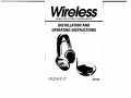
WIRELESS STEREO HEADPHONES
INSTALLATION AND
OPERATING INSTRUCTIONS
AW720
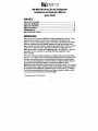
A. Adjustable Headband
B. Battery Compartment Cover
Wireless Stereo Headphones
Installation and Operation Manual
C. Power ON/OFF Switch
Model AW720
D. Volume Control Wheel
E. Charge Input Jack
CONTENTS
Connect the Transmitter
Power the Headphones
Adjust the Transmitter
Tune the Headphones
More Helpful Information
Troubleshooting
Specifications & Features
4
5
6
7
7
9
11
F. Power Indicator Light
G. Tuning Indicator Light
H. Tuning Control Wheel
I. Audio Level Indicator Light
J. Charge Output Jack
INTRODUCTION
Advent Wireless Headphones expand and enhance your enjoyment of the audio
sources (TV, stereo, etc.) in your home. Like FM radio, the Advent Wireless
Headphone System's 900 MHz signals travel with ease through walls, floors, ceilings and other obstacles, delivering high-quality stereo sound to virtually anywhere
in or about the home. Resonator-controlled circuitry for drift- and static-free reception, coupled with outstanding range up to 300 feet*, make the possibilities for your
enjoyment of the Advent Wireless Headphone System nearly unlimited.
K. Transmitter Power Input Jack
L. Output Level Control Wheel
M. Audio Input Cable
The Advent Wireless Headphone System is compatible with most audio sources, i.e.
TVs, VCRs, stereo receivers/amps, personal stereos, boom boxes, DSS receivers,
and individual stereo component pieces (CD players, cassette players, etc.).
Because the headphones do not have line-of-sight restrictions imposed by infrared
technology-based systems, you have the freedom to use the headphones while
moving about freely within the transmitter's sending range - up to 300 feet* in all
directions. The contents of this manual cover various connection options and
detailed operating procedures for making the Advent Wireless Headphone System a
valued part of your lifestyle. If, after having reviewed the instructions, you have any
questions, please contact our Customer Service Department at 1-800-732-6866.
R. Headphone Adapter Plug
*Maximum range; results achieved may vary by environment.
S. Charge Cable
2
O~
N. Frequency Control Wheel
O. Antenna
~
AC Adapter
Q. "Y" Cable Adapter
R
))~
3
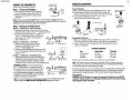
POWER THE HEADPHONES
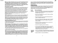
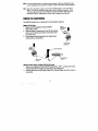
CONNECT THE TRANSMITTER
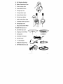
Connect the transmitter as follows:
The AW720 headphones are powered by 2AAA Nickel Cadmium (Ni-Cd) batteries.
Step 1 Power the Transmitter
1. Insert the power cord from AC Adapter (P)
into the Transmitter Power Input Jack (K).
2. Plug the AC Adapter (P) into any standard
wall outlet.
Note: There is no transmitter ON/OFFswitch. The transmitter is designed to be left
plugged in and powered at all times. If you will not be using the AW720 for an extended
period oftime, you may wish to unplug the AC Adapter.
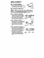
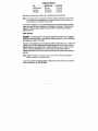
Insert the Batteries
1. Make sure the headphone Power ON/OFF Switch (C) is 1I0FF".
2. Remove Battery Compartment Cover (B) by pushing down
and out at the same time on the notch at the top of the cover.
3. Insert batteries following polarity ("+" and "-") as
diagrammed inside battery compartment.
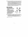
Step 2 Connect to an Audio Source
OPTION 1 - CONNECTING TO A STEREO RECEIVER
1. Connect the mini plug on the end of the Audio Input
Cable (M) to the mini jack on the IIV" Cable Adapter (Q).
2. Connect the dual RCA plugs on the other end
of the "V" Cable Adapter (Q) to the RCA-type
audio outputs of a stereo receiver/amp or
_
~ ~ .:f~f~~~<4'~~~:~ ~
.....
other audio source.
Output Jock' ,
j(
"d~ "
OPTION 2 - CONNECTING TO ATELEVISION
Audio
.•
YAdapter Cable (a)
1. Connect the mini plug on the end of the
Input Cable (M)
Audio Input Cable (M) to the mini jack
on the "V" Cable Adapter (Q).
2. Connect the dual RCA plugs on the other end of
the "V" Cable Adapter (Q) to the RCA-type audio
outputs of a TV.
OPTION 3 - CONNECTING TO A HEADPHONE JACK
1. Plug the mini plug on the end of the Audio Input
Audio
Cable (M) into the headphone jack. As needed
Input Cable (M)
use the Headphone Adapter Plug (R) to convert
the (3.5mm) mini plug to a full-size 1/4 headphone plug.
WARNING: DO NOT connect the RCA plugs of
Stereo Receiver
the "V" Cable Adapter to a speaker output on
the audio source. If you use the speaker output
of an audio source to connect the transmitter,
Headphone
you will permanently damage the transmitter. It
Adapter Plug (R)
is designed to work with RCA-type line/variable
outputs or headphone outputs only.
Note: For more information on hooking up and using the transmitter with various
ouputs, please see MORE HELPFUL INFORMATION beginning on Page 7.
T~n:er
o·~~
11
4
Battery Compartment
Cover (B)
b@
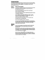
Charging Ni-Cd Batteries
1. Make sure headphone Power ON/OFF Switch (C) is "OFF". Connect one
end of Charge Cable (S) to Charge Input Jack (E) on the headphone.
2. Connect the other end of Charge Cable (S) to Charge Output Jack (J)
on back of transmitter.
CHARGE SCHEDULE
Use
Initial charge
Average
Extended
Charge Time
24 hours
10-12 hours
16-18 hours
PlayTime
5-6 hours
3-4 hours
5-6 hours
Play time as shown above reflects use of batteries in good condition.
Note: The charger will not overcharge the batteries if left on charge longer than
shown above. If you will not use the headphones for an extended period of time,
it is recommended you unplug the charger Qable.
For maximum battery life, it is recommended that you fully discharge the batteries about
once every 30 days, followed by an Extended Use charge. To discharge the batteries,
simply leave the headphones turned "ON" until the Power Indicator Light goes out.
About Batteries
WARNING: The AW720 built-in charger will charge Ni-Cd batteries only. DO NOT
attempt to recharge alkaline or rechargeable alkaline batteries as this will damage
the headphones and/or transmitter.
I
5
Over time, with repeated use, Ni-Cd batteries will eventually wear out. If, after a full
charge, you notice a) dramatically decreased playing time, b) the Power Indicator
Light begins to dim quickly and/or c) static interference occurs within a short time
of turning the headphones on, it may be time to replace the batteries.
Note: Battery life depends on frequency of use, time, and care (fully discharging
the batteries regularly, as described above.)
If you have questions regarding battery replacement, please contact our Customer
Service Depa rtment at 1-800-732-6866.
Using Optional Alkaline Batteries
The AW720 headphones can also be powered by 2AM alkaline batteries. You may
experience slightly longer play time with alkaline batteries but you will not be able
to recharge them, as you can with Ni-Cds.
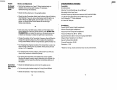
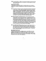
ADJUST THE TRANSMITTER
Adjust the transmitter as follows:
TUNE THE HEADPHONES
Adjustable
Headband (A)
Adjust the headphones as follows:
1. Disconnect the Charge Cable (S) from the
headphone Charge Input Jack (E) if connected.
2. Use the headphone Power ON/OFF
Switch (C) to turn the headset "ON."
3. Turn the Tuning Control Wheel (H) until the
Tuning Indicator Light (G) illuminates red,
indicating the headset is tuned to the
signal from the transmitter.
4. Adjust Headband (A) for comfort.
5. Adjust Volume (D) as desired.
/
'"
~@
~
Tuning
Contro/~
Wheel (H)
Switch (C)
Charge
,·~~l
Volume Control
Wheel (D)
Charge
Input
Jack (E)
Note: After fine tuning, interference in the form ofstatic and/or distortion can sometimes be heard. If this occurs, confirm the transmitter/headphone adjustments and indicators. If the problem persists, refer to the TROUBLESHOOTING section of this manual.
Step 1 Turn ON your Audio Source (i.e. Stereo Receiver, TV, etc.) so that you
MORE HELPFUL INFORMATION
can hear sound coming from the source.
About Fixed-Level Outputs
A fixed-level, or line-level audio output is considered ideal since it provides an audio
signal unchanged by adjustments to the audio source (stereo, etc.) volume control.
Step 2 Pivot the Antenna (0) to the upright vertical position.
Step 3 Set the Transmitter "Level"
1. Set the Frequency Control Wheel (N) to its midpoint
2. Turn the Output Level Control Wheel (L) all the
way to the left (your left when looking at the
transmitter controls), as shown.
3. Check status of Audio Level Indicator Light (I). If it
flickers intermittently (about half the time),
proceed to TUNE THE HEADPHONES.
4. If Audio Level Indicator Ught is on solid red or flickering
very rapidly, turn Output Level Control Wheel slowly
back to the right until light flickers intermittently.
g~~~~/::~el (L)
(Turn to Left)
Hint: Fixed-level audio outputs from stereo receivers/amps will typically be designated as Tape, Tape 1, and Tape 2 outputs, OAT (digital audio tape) outputs, VCR
audio output connections, and auxiliary audio outputs. Tape, Tape 1, Tape 2 and
OAT outputs are usually marked as ITAPE OUTPUT;' ITAPE OUT;' ITAPE REC,' or
TAPE RECORD.' Jacks designated for phono, CD, LD, DVD or tape playback (PB) are
inputs and will not work for purposes of installing the transmitter.
Frequency
Control Wheel (N)
Note: If the light does not flicker, confirm secure connection of the AC Adapter. If
the light still does not flicker, confirm secure connection to the audio source output.
If there is still no response, leave the Output Level Control Wheel completely to the
left (as shown) and see the following Note.
Note: If the transmitter is connected to a variable output (i.e. headphone jack, TV
audio out) on the audio source, leave the Output Level Control Wheel turned all the
way to the left (as shown) and adjust the volume on the audio source up or down
as necessary to make the Audio Level Indicator Light flicker intermittently. If you
are unclear as to the kind of output (variable or fixed) you are using, please see
MORE HELPFUL INFORMATION on the following page.
6
Fixed-level outputs from TVs are usually marked as 'Constant,' 'Fixed,' or 'Select.' If
they are not marked as such, they are probably variable outputs (see "About
Variable-Level Outputs," on Page 8).
Outputs from VCRs are almost always fixed.
Hint: When connecting to the fixed audio outputs of a VCR, remember that for the
wireless system to work, the VCR must be active. In other words, turn the TV on to
the channel you would normally use to watch a videotape (channel 3 or 4), turn the
VCR on, then press the TVNCR button on your VCR remote control one time to
make the VCR the controlling piece of equipment. At this point whatever channel is
showing on the tuner for the VCR should be the channel playing on the TlI. Change
channels on the VCR. This configuration gives independent volume control through
the TV (using the TV remote control) and at the headphones. This allows others in
the room to listen to TV at volume levels they find comfortable, and you to listen
through the headphones at volume levels you find acceptable.
7
Hint: If your VCR (or other RCA-type audio source you are connecting to) is mono (a
single audio output), you need to acquire another RCA "Y" Cable. It differs from the
"Y" Cable Adapter included in this kit It will have a single male RCA plug and 2
female RCA jacks. Connect the dual RCA plugs from the "Y" Cable Adapter (a) to
the 2 female RCA jacks on the second "Y" cable, then connect the single male RCA
plug of the second "Y" cable to the single audio output of the VCR.
About Variable-Level Outputs
A variable-level output, such as a headphone jack or certain RCA-type outputs, provides an audio signal to the transmitter that changes in relation to volume adjustments on the audio source. As the volume of the audio source goes up and down,
so too does the audio signal strength sent to the transmitter. This can affect the
quality of sound you hear at the headphones, and may require increasing or
decreasing the volume level of the audio source to achieve a suitably strong audio
signal for use with the AW720 system. For more information on how to use the
AW720 with variable outputs, see the following section, "About Using the
Headphones with a TV".
(see your TV owners manual). Once the speakers are off, turn the TV volume up
high enough to make the Audio Level Indicator Light flicker intermittently. To return
the TV to normal use, simply adjust the volume back to a normal level and turn the
speakers back on.
TROUBLESHOOTING
The following troubleshooting guide takes you through some of the more common
problems and corrections associated with the installation and/or operation of a
wireless system. If the problem persists, please call 1-800-732-6866 and a knowledgeable Customer Service Representative will assist you.
Trouble
Checks and Adjustments
No Sound
• Check that the AC Adapter is fully inserted into the wall outlet and
the power cord from the AC Adapter is firmly connected to the
Transmitter Power Input Jack.
• Check that the headphones are turned "ON" and the red Power
Indicator Light is brightly lit.
Hint: On most bookshelf-type or compact stereo systems, inserting a headphone plug
into the headphone jack results in automatic cutoff of the stereo system speakers.
Hint: Most TVs, regardless of age or price, have variable outputs. If you are unsure
which, if any of your outputs is fixed, refer to the TV instruction manual. Some TVs
• Check that the batteries are firmly seated following polarity as
shown in the battery compartment.
have outputs that can switch between variable and fixed. Refer to the TV instruction manual. When given a choice, fixed is always recommended.
• Check that the batteries are charged and/or "good." (If using NiCd, try recharging; be sure they are capable of accepting and
holding a charge)
About Using the Headphones with a TV
Wireless headphones are frequently used so that one person with hearing difficulty
can listen to TV at a sufficiently high volume level while others in the room listen to
the TV at normal volume levels.
• Check that the audio source (stereo, TV, etc.) is turned on and
providing sound as it normally should.
Hint: If you want to use the headphones to listen to TV independent of the volume
from the ~ and your TV has variable outputs, it is recommended you connect the
transmitter to the VCR, as described in the second HINT under "About Fixed-Level
Outputs. " This configuration gives you a fixed-level output for independent volume
• Check that the headphone volume is turned up.
• If you are using a Tape 2 Monitqr output from your receiver/amp
as the audio output, check that you have pressed the Tape
Monitor/Tape 2 button on the front of the receiver. This will turn on
theTape 2 outputs, which may not be active.
control at the headphones, while others in the room can turn the TV volume up and
down (even all the way down) without interfering with what you hear.
In another variation, there are those who wish to listen to TV in such a way that no
sound comes from the TV speakers.
Hint If you wish to use the headphones in such a way that you are the only person
who can hear the audio from the TV (e.g. use them in bed while another person in
the room is sleeping), and there is no VCR to connect to, use the following configuration: Connect to the variable audio outputs of the ~ then turn the TVs internal
speakers OFF. Most - but not all- TVs will have this capability, and will be accomplished either through the on-screen menu for the TV or using an external switch
8
No Sound/
Distortion/
Static
• Check that the headphone Tuning Indicator Light is illuminated red.
If not, adjust theTuning Control Wheel until the light illuminates red.
• Check the batteries - they may be weakening.
9
Trouble
Checks and Adjustments
SPECIFICATIONS & FEATURES
NoSoundl
• Confirm the batteries are"good." When batteries begin to
weaken, there can be static breakup. If necessary,
replace/recharge the batteries.
Transmitter
Omnidirectional
Effective Transmitting Range: Up to 300 feet*
Adjustable Audio Level Input
Variable Frequency Adjustment between 912.5 and 914.5 MHz
Line Audio Input with 3.5mm Stereo Mini Plug plus 1/4"
and Composite "v" Cable Adapters
UL-Listed AC Adapter
Distortion!
Static
• Check that the antenna is in the upright position.
• Check that the Transmitter Audio Level Indicator Light is flickering
intermittently. If you are using a fixed output and the light is on
solid or flickering very rapidly, or if the light is not on at all,
adjust the Output Level Control Wheel so that the light
flicke rs intermittently.
or
• If you are using a variable output, make sure the Output Level
Control Wheel is all the way left (as shown under ADJUST THE
TRANSMITTER), and adjust the volume on the audio source up
or down as necessary to make the light flicker intermittently.
• Change the position of the Transmitter Frequency Control Wheel to
change the operating frequency. Then readjust the headphone
Tuning Control Wheel until the Tuning Indicator Ught illuminates red.
• Try changing the physical location of the transmitter. Locate it as
high and free of obstruction as possible. Avoid placing directly
on top of a TV, if possible.
Headphones
Power ON/OFF switch (right headphone)
Volume Control (right headphone)
Frequency Fine Tuning (left headphone)
Frequency Response: 20 Hz - 20 kHz
Speaker Element: 32mm, litanium-Impregnated Mylar
Magnet Type: Neodymium Iron Boron
Signal-To-Noise Ratio: 60 dB
Channel Separation: 30 dB
Distortion: < 1.5%
*Maximum range; results achieved may vary by environment.
• Try changing the antenna position, particularly if you think you
may be near maximum transmitting range.
• Try moving the transmitter and headphones closer together.
Sending the signal through certain materials, such as glass, tile,
and metal, can decrease the effective transmitting distance of
the system.
Sound from
One Earpiece
Only
• Check the left/right balance control on the audio source
• Try fine tuning the headset using the Tuning Control Wheel.
• Check the batteries - they may be weakening.
10
11
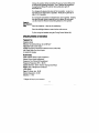
WARRANTY
ONE YEAR LIMITED WARRANTY
Recoton Corporation (the Company) warrants to the original retail purchaser of this product that should
the product or any part thereof be proven defective in material or workmanship within One Year from the
date of original purchase, such defects will be replaced without charge for parts or labor. This warranty
does not apply to any incidental or consequential damages.
To obtain replacement within the terms of this warranty, the product should be delivered, transportation
prepaid, to the Dealer where purchased or to the Company, along with proof of date of purchase. Call
1-800-RECOTON to obtain information regarding the procedure for proper return of your product, if your
Dealer does not honor the warranty. This warranty is valid in the USA and Canada only.
THIS WARRANTY DOES NOT APPLY TO ANY PRODUCT OR PART THEREOF WHICH HAS BEEN DAMAGED THROUGH ALTERATION, MISHANDLING, MISUSE, NEGLECT OR ACCIDENI THIS WARRANTY IS
IN LIEU OF ALL OTHER WARRANTIES, EXPRESSED OR IMPLIED, AND NO PERSON OR REPRESENTATIVE IS AUTHORIZED TO ASSUME FOR THE COMPANY ANY OTHER LIABILITY IN CONNECTION WITH
THE SALE OF THIS PRODUCI SOME STATES DO NOT ALLOW LIMITATIONS ON HOW LONG AN
IMPLIED WARRANTY LASTS OR THE EXCLUSION OR LIMITATIONS OF INCIDENTAL OR CONSEQUENTIAL DAMAGE SO THE ABOVE LIMITATIONS OR EXCLUSIONS MAY NOT APPLY TO YOU. This warranty
gives you specific legal rights and you may also have other rights which vary from state to state.
NON-WARRANTY SERVICE
If non-warranty service is required, the product may be sent to the Company for repai.r/replacement,
transportation prepaid, by calling 1-800-RECOTON for details, complete instructions, and service
fee charges.
A Division of Recoton® Corp.
2950 Lake Emma Road
Lake Mary, FL 32746
© 1999 Recoton Corp.
MADE IN CHINA
AD25888
15721-0-2
2/99
IMPORTANT! READ INSTRUCTIONS BEFORE HOOK-UP
PLEASE SEND ALL
CORRESPONDENCE TO:
2950 Lake Emma Road
Lake Mary, Florida 32746
©1998 Recoton Corp.
Add
first class
postage
$!\DVE"T
2950 Lake Emma Road
Lake Mary, Florida 32746
w
R
E
s
E
L
s
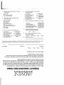
PRODUCT REGISTRATION FORM
Thank you for purchasing this Advent Wireless Product. At Advent, we're dedicated not
only to producing a superior product, but to providing the very best customer service possible. As
part of our ongoing effort to better understand you, the Advent customer, we ask that you fill out
this Registration Card and return it within 15 days of purchase. The information you provide will
help us to develop new products, improve on existing products, and ensure that we are providing
the kind of customer service you deserve and expect of Advent.
By returning this Registration Card, Advent will have your purchase information on file. If you
should lose your receipt, this Advent Registration Card will serve as proof-of-purchase for
insurance and/or warranty purposes.
Thank you for your time and assistance.
o Mrs.
OMr.
o Miss
OMs.
Last Name
First Name
1 1 1 1
1
1
1
Middle Initial
U
1
Apt. No.
Address
1 1 1
City
State
Zip
1
LLJ
1
1
Date of Purchase
MM
DD
YY
Ll..-l
Ll..-l
Ll..-l
Model Number AW
1.
1.
2.
3.
4.
2.
3.
I~.I. . .-.L.1--I,,1--I1
Marital Status
D Single
D Married
D Divorced
D Widowed
7.
Age
8.
D
2. D
3. D
4. D
5. D
1.
1
E-mail Address
Phone Number
Serial Number
1 --&--.&.---.I_.&....I 1 1
Amount Paid $
1
......__- - - ' - - - 1
30-49
Education
1. D High School
2. D Some College
3. 0 Completed College
4. 0 Graduate or Doctorate Studies
LLJ
Family income level (optional)
D
D
3. D
1.
2.
Under$15,000
$15,000-24,999
$25,000-49,999
4. D $50,000-74,999
5. D $75,000-100,000
6. D Over $100,000
Name of the store where you purchased?
Under 18
18-29
50-65
Over65
- - - 1 -- - 1 .- - - 1
L.-
1 1 1 1 1 I 1 1 1 I 1 1 1 1 1 1 1 1
9.
Where did you first hear about Advent Wireless Products?
1.
2.
3.
4.
5.
6.
D Friend/Family
D Salesperson
D Magazine Advertisement
D Previous Advent Owner
D Store Advertisement
0 TV Advertisement
10. What is the primary reason for this purchase? (check one)
Profession
4.
1.
2.
3.
4.
5.
6.
5.
D
D
D
D
D
D
Administrator/Clerical 7.
8.
Instructor/Teacher
9.
Homemaker
Management
10.
Professional
11.
Retired
D
D
D
D
D
Sales/Marketing
Self Employed
Skilled Laborer/
Tradesmen
Student
Technical
Not including yourself, what are the genders and ages
of children and other adults living in your household?
1.
2.
0
4. D
3.
2.
0
0
3.
4.
D
1.
6.
D
Female
Age (in years)
o
D
o
LL.J
LL.J
LL.J
LL.J
o
Do you
1.
2.
3.
D
D
D
Own home
Rent
Other
_
Music Playback
N Audio Playback
Video/Home
Theater Playback
Use outside-gardening,
garage, poOl
5.
0
Use Inside-exercising,
household tasks
Reelacement
of Speakers
Gift
Privacy-for use while
mate is sleeping
0
7. 0
8. 0
6.
11. Did you purchase for
assistance with a hearing impairment?
OV
o No one else in household.
Male
0
0
ON
12. What is the most important reason inAuencing your
purchase of this Advent wireless product?
1.
2.
3.
0
0
5.
6.
7.
8.
9.
10.
11.
0
0
D
0
0
0
0
0
4.0
Sound Quality
Appearance
Reputation
Value
Magazine Review
Technical Specifications
Ease of Operation
Previous Advent Owner
Salesperson Recommendation
Friend/Family Recommendation
Features
Continued on back.
13. Did you buy this product by itself or with a stereo
or video system?
1.
1. D By itself
2. D With audio products
3. D With video products
2.
3.
4.
5.
6.
14. What made you choose the Advent brand?
(check all that apply)
1. D
2. D
3. D
4. D
5. D
6. D
7. D
8. D
Do you plan to purchase in the next year?
(cheek all that apply)
16.
Sound Quality
Appearance
Reputation
Ease of Operation
Previous Advent Owner
Salesperson Recommendation
Features
Wireless
17.
0
9.0
0
8.
0
9.
D
After-market
Car Stereo
Computer with
Internet Access
~o~e Theater
ys em
Rank your experience with the dealer (1-5; 5 is best)
OV
Car Stereo
Computer with
Internet Access
Home Theater
System
19.
0
0
0
0
0
3 4
5
0 0 0
0 0 0
0 0 0
D D 0
0 0 0
ON
How would you rate the performance of your
Advent wireless product?
o Excellent
20.
0
0
0
0
0
Would you consider purchasing other
Advent wireless products in the future?
7. DAfter-market
8.
7.
1 2
Do you currently own: (cheek all that apply)
1. D CD Player
2. D MiniDisc PlayerIRee.
3. 0 Laser Disc Player
4. 0 DVD Player
5.0 Digital Satellite System
6. 0 Cellular Phone
CD Player
0 MiniDisc PlayerIRec.
0 Laser Disc Player
0 DVD Player
D Digital Satellite System
0 Cellular Phone
1. Helpfulness
2. Product Knowledge
3. Overall Buying Experience
4. Product display, Quality of Display
5. Product Demonstration
18.
15.
0
0
Very Good
0
Fair
0
Additional Comments:
Poor
_
*The information you provided on this registration card will be held in strictest confidence and will not be made available to other companies
for telemarketing or sales purposes. This information, in total, will be the sole property of Recoton Corporation, Lake Mary, Florida.
n
awoN
IOH!UI alPp!w
awoN
~SJ!j
'swD
SS!wD
°a:>uo~s!SSO pUO aW!~
'SJW D
~sol
'JWO
JnoA JOI noA ~UO~l
°sasodJnd AJUOJJOM JO/PUO a:>UOJnSU!
JOI aso~:>Jnd-IO-IOOJd so aAJas II!M pJO) UO!~OJ~S!6a~ ~UaApv S!~~ '~d!a:>aJ JnoA asol Plno~s
noA II °alH uo uOHOWJOIU! aso~:>Jnd JnoA aAo~ II!M ~uaApv 'pJO) UOHoJ~s!6a~ S!lfl 6u!uJn~aJ Aca
°tUaApV IO t:>adxa puo aAJasap noA a:>!AJas Jawotsn:> IO PU!~ a~t
6U!P!AOJd aJO aM tO~ aJnsua puo 's~:>npoJd 6uHs!xa uo aAoJdw! 'st:>npoJd Mau dOlaAap 0t sn dla~
II!M ap!AoJd noA uOHOWJOIU! a~l oaso~:>Jnd IO sAop q L U!lfJ!M~! uJflJaJ puo pJO) UO!~OJ~S!6a~ S!lfJ
~no IIH noA ~olfJ ~SO aM 'Jawo~sn:> ~uaApv alfl'nOA puotsJapun Ja~a9 0t ~oHa 6u!o6uo Jno IO ~od
sv °aI9!ssod a:>!AJas Jawotsn:> tsa9 luaA a~t 6U!P!AOJd 0t ~n9 't:>npoJd JO!Jadns 0 6u!:>npoJd 0t AIUO
tOU pato:>!pap aJ,aM '~uaApv tv °t:>npoJd ssalaJ!M tuaAPV S!~t 6u!so~:>Jnd JOI noA ~uo~l
WlIO:l NOIJ.YlIJ.SIOili J.)naOlid
s
s
3
,
3
H
M
l'3I\OV$
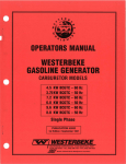
900 MHz WIRELESS STEREO HEADPHONES
INSTALLATION AND
OPERATING INSTRUCTIONS
AW720
900 MHz Wireless St6reo Headphones
Installation and Operation Manual
Model AW720
CONTENTS
Cennect the Transmitter
Pctwer the Headphones
Adiust the Transmitter
Replace the Battery
Troubleshooting
Specifications & Features
4
6
8
9
10
11
INTRODUCTION
Thank you for your purchase of 900 MHz Wireless Headphones by Advent. These
headphones will expand and enhance your enjoyment of the various audio
sources - such as TV and stereo - found in your home. like FM radio, the Advent
Wireless Headphone System's 900 MHz signals travel with ease through walls,
floors, ceilings and other obstacles, delivering high-quality stereo sound to virtually
anywhere in or about the home. Resonator-controlled circuitry for drift- and
static-free reception, coupled with outstanding range - up to 300 feet* - make the
possibilities for your enjoyment of the Advent Wireless Headphone System
nearly unlimited.
The Advent Wireless Headphone System is compatible with most potential audio
sources, i.e. TVs, VCRs, stereo receivers/amps, personal stereos, boom boxes, DSS
receivers, and individual stereo component pieces (CD players, cassette players,
etc.). Because the headphones do not have the line-of-sight restrictions imposed
by infrared technology-based systems, you have the freedom to use the
headphones while moving about freely within the transmitter's range. The contents
of this manual cover various connection options and detailed operating procedures
for making the Advent Wireless Headphone System a valued part of your lifestyle.
If, after having reviewed the instructions, you have any questions, please contact
our Customer Service Department at 1-800-732-6866.
* Range will vary by environment.
2
A. Self-Adjusting Headband
B. Battery Compartment Cover
C. Power Indicator Light
D. Power ON/OFF Switch
E. Charge Input Jack
F. Tuning Indicator Light
G. Volume Control Wheel
H. Tuning Control Wheel
I. Audio Level Indicator Light
J. Transmitter Power Input Jack
K. Charge Output Jack
L. Output Level Control Wheel
B
t
H
M. Right Audio Input Jack
N. left Audio Input Jack
~
O. Frequency Control Wheel -
P. Charge Cable
Q. Transmitter AC Adapter
R. Dual RCA Cable
S. "V" Cable Adapter
T. Headphone Adapter Plug
U. AAA Alkaline Batteries (x2)
I
~r.~
rffiTIu
L MNOKJ
~
~ creJ
3
@b
CONNECT THE TRANSMITTER
Connect the transmitter as follows:
Stu1
Transmitter Power
Input Jack (J)
Power the Transmitter
1. Insert the power cord from AC Adapter (Q) into
the Transmitter Power Input Jack (J).
2. Plug the AC adapter into any sta(ldard wall outlet.
~~
Transmitter AC
Adapter(Q)
Stu 2 Connect to an Audio Source
WARNING: DO NOT connect the Dual RCA cables to a speaker output on the
audio source. If you use the speaker output of an audio source to connect the
transmitter, you will pennanently damage the transmitter. It is only designed to
work with RCA-type line/variable outputs or headphone outputs only.
OPTION 1
CONNECTING TO A STEREO RECEIVER
1. Connect one end of the color-coded Dual
RCA Cable (R) to the color-coded left/Right
Audio Input Jacks (M,N) on the transmitter.
2. Connect the other end of the Dual RCA
Cable to the RCA-type audio outputs of a
stereo receiver/amp or other audio source.
OPTION
2
,.-
rtL:~
/jR Audio
Input Jacks (M, N)
CONNECTING TO A TELEVISION
1. Connect one end of the color-coded Dual RCA
Cable (R) to the color- coded left/Right Audio
Input Jacks (M, N) on the transmitter.
2. Connect the other end of the Dual RCA
Cable to the RCA-type audio outputs of
aN.
OPTION
3
,-
~ ""
l/RAudio
Input Jacks (M, N)
CONNECTING TO A HEADPHONE JACK
1. Connect one end of the color-coded Dual RCA
Cable (R) to the color-coded left/Right Audio
Input Jacks (M,N) on the transmitter.
2. Connect the other end of the Dual RCA Cable
to the color-coded "v" Cable Adapter (S).
3. Plug the 3.5mm mini plug from the "v"
/jR Audio
Cable Adapter into the headphone jack
Input Jacks
(M, N)
(as needed, use the Headphone Adapter
Plug (T) to convert the 3.5mm plug to a 1/4"
plug).
4
Dual RCA Cable (R)
.:f; f;ft ~
~-
~
Dual RCA Cable (R)
Dual RCA
Cable (R)
uyu Cable
Adapter(S)
N.te: If you select Option 1 or Option 2 to connect the transmitter, the audio level will be
fixed or variable, depending on your equipment. If you select Option 3, the audio
level will be variable.
AlOUT FIXED-LEVEL OUTPUTS
A fixed-level, or line-level audio output is considered ideal since it provides an
audio signal unchanged by adjustments to the audio source (stereo, etc.) volume
control.
Hint: Fixed-level audio outputs from stereo receivers/amps will typically be designated
as Tape, Tape 1, and Tape 2 outputs, OAT (digital audio tape) outputs, VCR audio
output connections, and auxiliary audio outputs. Tape, Tape 1, Tape 2 and OAT
outputs are usually marked as TAPE OUTPUT,' TAPE OUT,' 'TAPE REC,' OR TAPE
RECORD.' Jacks designated for phono, CD, LD, DVD or tape playback (PB) are
inputs and will not work for purposes of installing the transmitter. Fixed-level
outputs from TVs are usually marked as 'Constant,' 'Fixed, , or 'Select.' If they are
not marked as such, they are probably variable outputs (see "About VariableLevel Outputs, " below). Outputs from VCRs are almost always fixed.
Hillt: When connecting to the fixed audio outputs of a VCR, remember that for the
wireless system to work, the VCR must be active. In other words, turn the TV on
to the channel you would normally use to watch a videotape (channel 3 or 4), turn
the VCR on, then press the TVNCR button on your VCR remote control one time to
make the VCR the controlling piece of equipment. At this point, you can watch TV
or a VHS tape through the VCR. When changing TV channels, remember to do so
through the VCR. This configuration gives independent volume control through the
TV (using the TV remote control) and at the headphones. This allows others in the
room to listen to TV at volume levels they find comfortable, and you to listen
through the headphones at volume levels you find acceptable.
Hi"t: If your VCR (or other RCA-type audio source you are connecting to) is mono (a
single audio output), you need to acquire an RCA "Y" Cable. It differs from the "Y"
cable included in this kit. It will have a single male RCA plug and 2 female RCA
jacks. Attach the dual RCA cables from the transmitter to the 2 female RCA jacks
on the "Y" cable, then connect the single male RCA plug of the "Y" cable to the
single audio output of the VCR.
ABOUT VARIABLE-LEVEL OUTPUTS
A variable-level output, such as a headphone jack or certain RCA-type outputs,
provides an audio signal to the transmitter that changes in relation to volume
adjustments on the audio source. As the volume of the audio source goes up and
down, so too does the audio signal strength sent to the transmitter. This can affect
the quality of sound you hear at the headphones.
5
Hillt: On most bookshelf-type or compact stereo systems, inserting a headphone plug
into the headphone jack results in automatir. cutoff of the stereo system speakers.
Hint Most TVs, regardless of age or price, have variable outputs. If you are unsure
which, if any of your outputs is fixed, refer to the TV instruction manual. Some
TVs have outputs that can switch between variable and fixed. Refer to the TV
instruction manual. When given a choice, fixed is always recommended.
POWER THE HEADPHONES
The AW720 headphones are powered by 2 AAA alkaline batteries
INSBlT THE BATIERIES
1. Make sure the headphone Power ON/OFF
Switch (0) is "OFF".
2. Remove Battery Compartment Cover (B) by pushing
down and out at the same time on the notch at the
top of the cover.
3. Insert batteries following polarity as diagrammed
inside battery compartment.
Battery
Compartment
Cover (B)
~
!
Power On/Off
Switch (0)
USING OPTIONAL NICKEL CADMIUM (Ni-Cd) BAmRIES
1. Make sure headphone Power ON/OFF Switch (0) is "OFF". Connect one end of
Charge Cable (P) to Charge Input Jack (E) on the headphone.
2. Connect the other end of Charge Cable (P) to Charge Output Jack (K) on back of
transmitter.
6
CHARGE SCHEDULE
USE
CHARGE TIME
PLAY TIME
Initial charge
Average
Extended
24 hours
10-12 hours
16-18 hours
5-6 hours
3-4 hours
5-6 hours
Play time as shown above reflects use of batteries in good condition.
Note: The charger will not overcharge the batteries if left on longer than shown above.
If you will not use the headphones for an extended period of time, however, it is
recommended you unplug the charger cable.
For maximum battery life, it is recommended that you fully discharge the batteries
about once every 30 days, followed by an Extended Use charge. To discharge the
batteries, simply leave the headphones turned "ON" until the Power Indicator
Light (C) goes out.
ABOUT BATTERIES
WARNING: The AW720 built-in charger will charge Ni-Cd batteries only. DO NOT
attempt to recharge alkaline or rechargeable alkaline batteries, as this will damage
the headphones and/or transmitter.
Over time, with repeated use, Ni-Cd batteries will eventually wear out. If, after a full
charge, you notice a) dramatically decreased playing time, b) the Power Indicator
Light (C) begins to dim quickly and/or c) static interference occurs within a short
time of turning the headphones on, it may be time to replace the batteries.
Suitable replacements of a like or similar type should be available where batteries
are sold.
N",.: Battery life depends on frequency of use, time, and care (fully discharging the
batteries regularly, as described above.)
If you have questions regarding battery replacement, please contact our Customer
Service Department at 1-800-732-6866.
7
ADJUST THE TRANSMITTER
Adjust the transmitter as follows:
STEP
1
TURN
ON
YOUR AUDIO SOURCE
(i.e. Stereo Receiver, TV, etc.) so that you can hear sound coming from the source.
STEP
2
SET THE TRANSMITTER "LEVEL"
Audio Level
1. Set the Frequency Control Wheel (0) to its midpoint.
2. Turn the Output Level Control Wheel (L) all the way
to the right as shown.
3. Check status of Audio Level Indicator Light (I). If it
flickers intermittently (about half the time), proceed
to "Tune the Headphones".
4. If Audio Level Indicator Light is on solid red or
flickering very rapidly, turn wheel slowly back
to the left until light flickers intermittently.
~
~
If
Output Level Frequency
Control
Control
Wheel (L)
Wheel (0)
Note: If the light does not flicker, confirm secure
connection of the AC adapter to a "good" outlet.
If the light still does not flicker, confirm secure connection to the audio source
output. If there is still no response, leave the Output Level Control Wheel
completely to the right (as shown above) and proceed.
Hint: If the transmitter is connected to a ~ QIJJ.Jn!1 (i.e. headphone jack, TV audio
out) on the audio source, leave the Output Level Control Wheel turned all the way
to the right (as shown above) and adjust the volume on the audio source up or
down as necessary to make the Audio Level Indicator Light flicker intermittently.
ABOUT USING THE HEADPHONES WITH A TV
Wireless headphones are frequently used so that one person with hearing difficulty
can listen to TV at a sufficiently high volume level while others in the room listen to
the TV at normal volume levels.
Hint: If you want to use the headphones to listen to TV independent of the volume from
the TV, and your TV has variable outputs, it is recommended you connect the
transmitter to the VCR, as described in the second HINT under "About Fixed-Level
Outputs (pg. 5)." This configuration gives you a fixed-level output for independent
volume control at the headphones, while others in the room can turn the TV
volume up and down (even all the way down) without interfering with what you
hear.
In another variation, there are those who wish to listen to TV in such a way that no
sound comes from the TV speakers.
8
Hint If you wish to use the headphones in such a way that you are the only person who
can hear the audio from the TV (e.g. use them in bed while another person in the
room is sleeping), connect as described in the above Hint. However, if there is no
VCR to connect to, use the following configuration: Connect to the variable audio
outputs of the TV, then turn the TVs internal speakers OFF. Most, but not all, TVs
will have this capability, and will be accomplished either through the on-screen
menu for the TV or using an external switch (see your TV owner's manual). Once
the speakers are off, turn the TV volume up high enough to make the Audio Level
Indicator Light flicker intermittently. To return the TV to normal use, simply adjust
the volume back to a normal level and turn the speakers back on.
DIKE THE HEADPHONES
Adjust the headphones as follows:
1. Disconnectthe Charge Cable (P) from
the headphone Charge Input Jack (E) if
connected.
2. Use the headphone Power ON/OFF
Switch (0) to turn the headset "ON".
3. Turn the Tuning Control Wheel (H) until
the Tuning Indicator Light (F) illuminates
red, indicating the headset is tuned to
the signal from the transmitter.
4. Adjust the headband for comfort.
Adjust volume as desired.
Tuning
Indicator
Light (F)
t
Tuning Control
Wheel (H)
Note: The AW720 headphones will receive the audio signal from the transmitter through
walls, ceilings, floors, etc., up to 300 feet*. It should be noted, however, that
interference in the form of static and/or distortion can sometimes be heard. If this
occurs, confirm the transmitter/headphone adjustments and indicators.
If the problem persists, refer to the TROUBLESHOOTING section of this manual.
* Range will vary by environment.
9
TROUBLESHOOTING
The following troubleshooting guide takes you through some of the more common problems
and corrections associated with the installation and/or operation of a wireless system. If the
problem persists, please call 1-800-732-6866 and a knowledgeable customer service
representative will assist you.
TIOUBLE
No Sound
CHECKS AND ADJUSTMENTS
Check that the Transmitter AC Adapter (Q) is fully inserted into the wall outlet
and the power cord from the AC adapter is firmly connected to the
Transmitter Power Input Jack (J).
Check that the headphones are turned "ON" and red Power
Indicator Light (C) is lit brightly.
Check that the batteries are firmly seated following polarity as shown
in the battery compartment.
If using alkalines, check that the batteries are "good." If using
Ni-Cds, check that the batteries are charged and/or "good." (i.e.
capable of accepting and holding a charge).
Check that the audio source (stereo, TV, etc.) is turned on and
providing sound as it normally should.
Check that the headphone volume is turned up.
If you are using a Tape 2 Monitor output from your receiver/amp as
the audio output, check that you have pressed the Tape Monitor!Tape
2 button on the front of the receiver. This will turn on the Tape 2
outputs, which may not be active.
NoSoundl
Distortion!
Static
Check that the headphone Tuning Indicator Light (F) is illuminated
red. If not, adjust the Tuning Control Wheel (H) until the light
illuminates red.
Check that the transmitter Audio Level Indicator Light (I) is flickering
intermittently. If you are using a fixed output and the light is on solid,
or if the light is not on at all, adjust the Output Level Control Wheel (L)
so that the light flickers intermittently.
or
If you are using a variable output, turn the Output Level Control
Wheel (L) all the way right (as shown under "Adjust the Transmitter")
and adjust the volume on the audio source up or down as necessary
to make the light flicker intermittently.
10
Change the position of the transmitter Frequency Control Wheel (0)
to change the operating frequency. Then, readjust the headphone
Tuning Control Wheel (H) until the Tuning Indicator Light (F)
illuminates red.
Try changing the physical location of the transmitter. Locate it as
high and free of obstruction as possible. Avoid placing directly on
top of a TV, if possible.
Try moving the transmitter and headphones closer together. Sending
the signal through certain materials, such as glass, tile and metal,
can decrease the effective transmitting distance of the system.
SOIIRdln
0". Earpiece
Only
Check the batteries - they may be weakening.
Check the left/right balance control on the audio source.
Try fine tuning the headset using the Tuning Control Wheel (H).
SPECIFICATIONS & FEATURES
TRANSMITTER
Omnidirectional
Effective Transmitting Range: Up to 300 feet*
Adjustable Audio Level Output
Variable Frequency Adjustment between 912.5 to 914.5 MHz
Left / Right Audio Line Level Inputs
UL Listed AC Adapter
HEADPHONES
Power ON/OFF Switch (right headphone)
Volume Control (right headphone)
Frequency Fine Tuning (left headphone)
Frequency Response: 20 Hz - 20 kHz
Speaker Element: 32mm, Titanium-Impregnated Mylar
Magnet Type: Neodymium Iron Boron
4 Ohm Rated
Signal-To-Noise ratio: 60 dB
Channel Separation: 30 dB
Distortion: < 1.5%
* Range will vary by environment.
11
WARRANTY
ONE YEAR LIMITED WARRANTY
Recoton Corporation (the Company) warrants to the original retail purchaser of this product that should
the product or any part thereof be proven defective in material or workmanship within One Year from the
date of original purchase, such defects will be replaced without charge for parts or labor. This warranty
does not apply to any incidental or consequential damages.
To obtain replacement within the terms of this warranty, the product should be delivered, transportation
prepaid, to the Oealer where purchased or to the Company, along with proof of date of purchase. Call
1-800-RECOTON to obtain information regarding the procedure for proper return of your product, if your
Oealer does not honor the warranty. This warranty is valid in the USA and Canada only.
THIS WARRANTY OOES NOT APPLY T8 ANY PRODUCT OR PART THEREOF WHICH HAS BEEN
DAMAGED THROUGH ALTERATION, MISHANDLING, MISUSE, NEGLECT OR ACCIDENT. THIS
WARRANTY IS IN LIEU OF ALL OTHER WARRANTIES, EXPRESSED OR IMPLIED, AND NO PERSON OR
REPRESENTATIVE IS AUTHORIZED TO ASSUME FOR THE COMPANY ANY OTHER LIABILITY IN
CONNECTION WITH THE SALE OF THIS PRODUCT. SOME STATES DO NOT ALLOW LIMITATIONS ON
HOW LONG AN IMPLIED WARRANTY LASTS OR THE EXCLUSION OR LIMITATIONS OF INCIDENTAL OR
CONSEQUENTIAL DAMAGE SO THE ABOVE LIMITATIONS OR EXCLUSIONS MAY NOT APPLY TO YOU.
This warranty gives you specific legal rights and you may also have other rights which vary from state
to state.
NON-WARRANTY SERVICE
If non-warranty service is required, the product may be sent to the Company for repair/replacement
transportation prepaid, by calling 1-800-RECOTON for details, complete instructions, and service
fee charges.
A Division of Recoton® Corp.
2950 lake Emma Road
lake Mary, Fl32746
© 1998 Recoton Corp.
MADE IN CHINA
AD22359
15720-0-2
4/98