1
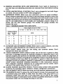
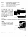
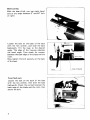
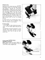
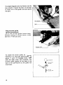
Jig Saw
MODEL 4301BV
Variable Speed
INSTRUCTION MANUAL
SPEC IFICAT IONS
L e n g t h of
stroke
M a x c u t t i n g capacities
Wood at 90'
1 Wood at 45' 1 S t e e l at 90'
Strokes
per
mln
I
Overall
length
Manufacturer reserves the rlght to change specifications wlthout notice.
* Note: Specifications may differ from country to country.
1
Net
weight
IMPORTANT
SAFETY INSTRUCTIONS
(For All Tools)
WARNING: WHEN USING ELECTRIC TOOLS, BASIC SAFETY PRECAUTIONS SHOULD ALWAYS BE FOLLOWED TO
REDUCE THE RISK OF FIRE, ELECTRIC SHOCK, AND PERSONAL INJURY, INCLUDING THE FOLLOWING:
READ ALL INSTRUCTIONS.
1. KEEP WORK AREA CLEAN. Cluttered areas and benches invite injuries.
2. CONSIDER WORK AREA ENVIRONMENT. Don’t use power tools in damp or
wet locations. Keep work area well lit. Don’t expose power tools to rain.
Don’t use tool in presence of flammable liquids or gases.
3. KEEP CHILDREN AWAY. All visitors should be kept away from work area.
Don’t let visitors contact tool or extension cord.
4. STORE IDLETOOLS. When not in use, tools should be stored in dry, and high
or locked-up place - out of reach of children.
5. DON’T FORCE TOOL. It will do the job better and safer at the rate for which
it was intended.
6. USE RIGHT TOOL. Don’t force small tool or attachment to do the job of a
heavy-duty tool. Don’t use tool for purpose not intended; for example, don’t
use circular saw for cutting tree limbs or logs.
7 . DRESS PROPERLY. Don’t wear loose clothing or jewelry.They can be caught
in moving parts. Rubber gloves and non-skid footwear are recommended
when working outdoors. Wear protective hair covering to contain long hair.
8. USE SAFETY GLASSES. Also use face or dust mask if cutting operation is
dusty.
9. DON’T ABUSE CORD. Never carry tool by cord or yank it to disconnect from
receptacle. Keep cord from heat, oil, and sharp edges.
10. SECURE WORK. Use clamps or a vise to hold work. It’s safer than using
your hand and it frees both hands to operate tool.
11. DON’T OVERREACH. Keep proper footing and balance at all times.
12. MAINTAIN TOOLS WITH CARE. Keep tools sharp and clean for better and
safer performance. Follow instructions for lubricating and changing accessories. Inspect tool cords periodically and if damaged, have repaired by
authorized service facility. Inspect extension cords periodically and replace
if damaged. Keep handles dry, clean, and free from oil and grease.
13. DISCONNECTTOOLS. When not in use, before servicing, and when changin!
accessories, such as blades, bits, cutters.
2
Total Length of Cord in Feet
0 - 25
26-50
51-100
1101-150
Ampere Rating
0
-
6
-
10
12
AWG
Not More
Than
More
Than
6
18
16
16
14
10
18
16
14
12
12
16
16
14
12
16
14
12
Not recommended
17. OUTDOOR USE EXTENSION CORDS. When tool is used outdoors, use only
extension cords intended for use outdoors and so marked.
18. STAY ALERT. Watch what you are doing, use common sense. Don’t
operate tool when you are tired.
19. CHECK DAMAGED PARTS. Before further use of the tool, a guard or other
part that is damaged should be carefully checked to determine that it will
operate properly and perform its intended function. Check for alignment of
moving parts, binding of moving parts, breakage of parts, mounting, and any
other conditions that may affect its operation. A guard or other part that is
damaged should be properly repaired or replaced by an authorized service
center unless otherwise indicated elsewhere in this instruction manual.
Have defective switches replaced by an authorized service center. Don’t
use tool if the switch does not turn it on and off.
20. GUARD AGAINST ELECTRIC SHOCK. Prevent body contact with grounded
surfaces. For example; pipes, radiators, ranges, refrigerator enclosures.
21. REPLACEMENT PARTS. When servicing, use only identical replacement parts.
22. POLARIZED PLUGS.To reduce the risk of electric shock, this equipment has
a polarized plug (one blade is wider than the other). This plug will fit in a
polarized outlet only one way. If the plug does not fit fully in the outlet,
reverse the plug. If it still does not fit, contact a qualified electrician to install
the proper outlet. Do not change the plug in any way.
3
VOLTAGE WARNING: Before connecting the tool to a power source (receptacle,
outlet, etc.) be sure the voltage supplied is the same as that specified on the
nameplate of the tool. A power source with voltage greater than that specified
for the tool can result in SERIOUS INJURY to the user-as well as damage to
the tool. If in doubt, DO NOT PLUG IN THE TOOL. Using a power source with
voltage less than the nameplate rating is harmful to the motor.
ADDITIONAL SAFETY RULES
1, Avoid cutting nails. Inspect for and remove all nails from the workpiece before operation.
2. Don't cut hollow pipe.
3. Do not cut oversize workpiece.
4. Check for the proper clearance beneath the workpiece before cutting so that
the blade will not strike the floor, workbench, etc.
5. Hold the tool firmly.
6. Make sure the blade is not contacting the workpiece before the switch is
turned on.
7. Keep hands away from moving parts.
8. When cutting through walls, floors or wherever "live" electrical wires may
be encountered, DO NOT TOUCH ANY METAL PARTS OF THE TOOL!
Hold the tool only by the insulated grasping surfaces to prevent electric shock
if you cut through a "live" wire.
9. Do not leave the tool running. Operate the tool only when hand-held.
IO. Always switch off and wait for the blade to come to a complete stop before
removing the blade from the workpiece.
11. Do not touch the blade or the workpiece immediately after operation; they
may be extremely hot and could burn your skin.
SAVE THESE INSTRUCTIONS.
4
Installing Makita jig saw blade
CAUTION :
Always be sure that the tool is switched off and unplugged before installing or removing
the blade.
Use the hex wrench to loosen the bolt,
With the blade teeth facing forward, insert
the blade into the blade holder as far as
it will go.
Make sure that the back edge of the blade
fits into the roller and tighten the bolt
securely with the hex wrench.
CAUTION :
Use a lubricant or cutting oil between the blade and roller when cutting iron or composition board, etc. Failure to do so will shorten the service life of your blade and roller.
Installing universal shank jig saw blade
CAUTION :
Always be sure that the tool is switched off and unplugged before installing or removing
the blade.
I f the universal blade clamp i s used, you
can use blades of other makes which have
a universal shank like the one shown in
the figure, with a blade width of 6.35 mm
( 1 /4").
Insert the blade into the blade holder as far
as it will go. Make sure that the end of the
blade shank reaches the bottom of the
inner s l i t and tighten the bolt securely with
the hex wrench.
Straight line or ot-ita1 cutting action
Conventional jig saws cut with a straight
line action, that is, the blade moves only
up and down in a straight line. Your saw
also cuts in this manner but, for softer
workpiece, an orbital cutting action can
be selected. Soft workpiece, like wood and
plastic permit deep penetration of individual saw teeth. The orbital action thrusts
the blade forward on the cutting stroke
and greatly increases cutting speed over
conventional jig saws. Harder workpiece
like metal should be cut using the straight
line cutting action or a very low orbital
setting. To select straight line or orbital
cutting, adjust the number on the saw.
6
1
I
I
The end o f the blade
shank should reach the
bottom of the inner slit
Position 0
-
Position I
- For cutting in soft steel, aluminum and hard wood.
Position I1
-
For cutting in soft steel, stainless steel and plastics.
For clean cuts in wood and plywood.
For cutting in wood and plywood.
For fast cutting in aluminum and soft steel.
Position 111 - For fast cutting in wood and plywood.
Switch action
Tool speed i s increased by increasing pressure on the trigger. To start the tool,
simply pull the trigger. Release the trigger
to stop. For continuous operation, pull the
trigger and then push in the lock button.
To stop the tool from the locked position,
pull the trigger fully, then release it. A
speed control screw is provided so that
maximum tool speed can be limited (variable). Turn the speed control screw clockwise for higher speed, and counterclockwise for lower speed.
Lock button
CAUTION :
Before plugging in the tool, always check to see that the trigger switch actuates properly
and returns to the "OFF" position when released.
Operation
Turn the tool on and wait until the blade
attains full speed. Then rest the base f l a t
on the workpiece and gently move the tool
forward along the previously marked cutting line. When cutting curves, advance the
tool very slowly.
CAUTION :
Failure to hold the tool base flush with the workpiece may cause blade breakage.
7
Bevel cutting
With the base tilted,. vou
can make bevel
,
cuts a t any angle between 0" and 45" (left
or right).
Loosen the bolt on the back of the base
with the hex wrench, and slide the base
backwards. Tilt the base to the desired
angle. The edge of the housing indicates
the bevel angle. Then check for contact
between the back edge of the blade and the
roller.
Now tighten the bolt securely on the back
of the base.
Roller
Front flush cuts
Loosen the bolt on the back of the base
with the hex wrench, then slide the base
backwards. Check the contact between the
back edge of the blade and the roller, then
secure the bolt.
8
I
.
Edge of housing
'1
Plunge cutting
Starting a cut a t other than the edge of the
workpiece without first drilling a starting
hole requires a "plunge cut". This can be
accomplished by tipping the tool forward
until the front end of the base rests against
the workpiece. Switch the tool on and
lower the back end of the tool slowly,
gradually allowing the blade to saw through
the workpiece until the base is able to s i t
flat on the workpiece. You may then proceed forward with the cut in a normal
manner.
If using a drill for a starting hole, bore a
hole over 12 mm (1/2") in diameter. Then
insert the blade in it and proceed.
Finishing edges
To trim edges or make dimensional adjustments, run the blade lightly along the cut
edges.
For smoother cutting of plywoods or other
materials with easily splintered surfaces,
transparent tape may be used over your
cutting line.
Using guide rule (Rip fence)
(optional accessory)
When cutting widths of under 150"
6")
repeatedly, use o f the guide r u l e will
assure fast, clean, straight cuts.
9
To attach the guide rule (rip fence), use the
hex wrench to loosen the bolt on the base
in front, slip in the guide rule and secure
the bolt.
Using circular guide
(optional accessory)
Use of the circular guide insures clean,
smooth cutting of circles (radius; under
200 mm; 7-7/8")
and arcs.
To attach the circular guide, use the pin,
inserting it in the center hole (arrow) and
secure it with the threaded knob. Then
slide the base of the tool forwards. The
circular guide attaches to the base of the
tool in the same manner as the guide rule
(rip fence).
10
F l i pin into
Metal cutting
Always use a suitable coolant (cutting oil)
when cutting metal. Failure to do so will
cause significant biade wear.
The underside of the workpiece can be
greased instead of using a coolant.
11
MA1NTENANCE
CAUTION :
Always be sure that the tool is switched off and unplugged before attempting to perform
inspection or maintenance.
Replacing carbon brushes
Remove and check the carbon brushes
regularly. Replace when they wear down
t o about 5 mm (3/16") or less. Keep the
carbon brushes clean and free to slip in the
holders. Both carbon brushes should be
replaced a t the same time. Use only Makita
carbon brushes.
I
I
I
L-
H
1
5 m m (3/16')
Use a screwdriver t o remove the brush
holder caps. Take ouit the worn carbon
brushesi, insert the Iiew1 ones and secure the
brush hlolder caps.
To maintain product SAFETY and RELIABILITY, repairs, any other maintenance or
adjustment should be performed by Makita Authorized or Factory Service Centers,
always using Makita replacement parts.
12
OPTIONAL ACCESSORIES
NOTE:
The accessories listed in this manual are available at an extra cost from your Makita distributor or Makita factory
service center. Service centers are listed on the warranty card packed with your tool.
CAUTION:
These accessories or attachments are recommended for use w i t h your Makita tool specified in this
manual. The use of any other accessories or attachments might present a risk of injury to persons. The
accessories or attachments should be used only in the proper and intended manner.
A n exception: Universal shank jig saw blades with a thickness of 1 m m - 1.25 mm (1/32"- 3/64")
and a length of 58 m m - 82 m m (2-9/32"
- 3-7/32").
Circular guide assembly
Part No. 123030-5
Guide rule
Part No. 1641 13-2
*Plastic case
Part NO.824418-9
Hex wrench 3
Part No. 783201 -2
Jig saw blade (Packed 5 each)
(Note)
Refer t o the next page for "Application" of each blade.
13
No.
6-24
No.
6 - 25
No
6-26
No
6-27
/3,6:.mmlt:dc:
H
55 m m thick
1118''
2 118"l
3
55 m m thick
1118''
2 lr8"l
H
H
3
55 mm thick
2 118"l
11/8"
H
3
5 5 mm thick
1188'' - 2-118")
3
~
~
~
~
q17&2
3
30 mm thick
1 18")
1118''
3
3 - 30 m m thick
1118"
1 lr8"l
3
~
~
~
mrj;Ahq!c7
10 mm thick
11 8"
3/8"1
~
Also ideal for cutting
stainless steel
for cutt,ng
th,ck n,ate,,alS
10 mm thlck
1118''
3/8"1
Ideal for scroll cutting
H
1 5
3 mm thick
I l r 1 6 " - 118")
H
14
Ol?,i43
1
6 m m thick
13/64"
lj4"j
1
3 mm thlck
(3)64"
1 8")
~
Ideal for scroll cutting
Aug - 2 6 84 US
JIG SAW
Model 4301BV
Note: The switch and other part configurations
may differ from country to country.
15
Aug - 2 4 4 4 US
MODEL 4301BV
ITEM
NO.
NO.
USED
DESCRIPTION
kw
MAWME
I
2
2
1
Screw M4x6 (With Washer)
46
47
48
2
Screw M4x10 (With Washer)
1
49
50
51
t
t
52
1
53
1
54
55
1
56
57
56
1
P,Otacto,
Stop Ring E - 3
Stop Ring E - 3
RBfal"e.
P," 4
P," 4
Roller
Rod
Screw M4x10
Screw M4x12
Base
Clamp Plate
Spring Washer4
Screw M 4 ~ 2 0
Handle Set (Wilh Item 79)
Screw M5x16 (With Washer)
CORD ASSEMBLY
(With Cord. Plug 8 Item €4)
Cor0 Guard
Screw M 4 ~ 1 6(Wllh Washer)
Slraln Rellsl
Switch
Screw M6x40 (With Washer)
Stop Ring E - 4
FIELD ASSEMBLY
Indication Labs1
Motor Hou~ing
Carbon Brush
Brush Holdet Cap
Screw M5x16 (Wilh Washer)
Rubber Pin 4
Handle Sel (With llem 61)
Screw M4128 (Wilh Washer)
Rubber Pin 4
Sbel Ball 4
Compression Spnng 4
Lever 23
Screw M4125 (With Washer)
Guida Pin
Flat Washer 8
1
1
Slide,
9
10
2
Screw M4x12
Slloer Plate
Needle BBanng 607
Retsining Ring SB
Screw M6xl6 (Wtth Washer)
5
6
7
11
12
13
14
15
16
17
19
20
21
22
23
24
25
26
27
26
29
1
1
1
2
1
1
1
1
1
1
1
1
1
1
Felt
i
4
Dust Plale
Screw M4x12 (With Washer)
1
1
1
I
1
1
1
30
I
31
1
32
33
24
1
1
1
1
1
1
35
36
37
38
39
40
41
42
43
Crank
Flat Washer 26
Balance Plate
Balance Plate
Flat Washer 35
Push Plate
Flat Washer 35
Helical Gear 51
Needle Bearing 810
Needle Beanng 810
Flat Washer 14
Ball Beanng 6oBLB
Insulation Washer
Flat Washer 10
ARMATURE ASSEMBLY
(With Ifem 26,27, 30 8 32)
Fan 68
Flat Washer 10
Ball Be"
W8LB
Bania piate
NulM6
Gear Housing
Flal Washer6
Stop Ring E - 4
Packing
Gear Shan
wmler 9
1
1
-
E
44
6
4
DESCRIPTION
Screw M4X20 (With Washer)
Rlve1&5
Name Plats
Gsai HouSlngCover
comprsor,on Spring 4
Sllda Plate
Slloer suppan
3
~
4
4
1
1
4
2
'itM G2D
45
56
W
61
62
63
€4
66
66
69
70
71
72
73
74
75
76
77
76
79
80
81
82
1
1
1
1
1
1
1
1
2
1
1
2
1
1
1
1
1
1
1
2
2
2
1
1
2
1
1
€4
86
i
1
4
86
1
87
1
83
__ -
Holder
Note The switch I
MAKrA LIMED ONE YEAR WARRANTY
Warranty Policy
Every Makita tool IS t h o r o u a l y inspected and tested before leaving the factory. It IS warranted to
be free of defects from worbnanrhip and matenals for the penod of ONE YEAR from the date of
orignal purchase. Should any trouble develop dunng this one-year penod, return the COMPLFTt
tool, freight prepaid, to one of Makm'r Factory or Authorized Service Centers. If inspectron shows
the trouble is caused bv defective workmanrhio or material. Makita will r e m u (or at OUI ontion.
replace) without charge.
This Warranty does not apply where:
repairs have been made or attempted by others.
repvrs are required because of normal wear and tear
The tool har been abused. misused or improperly maintained.
alteration%have been made to the tool.
IN NO EVENT SHALL MAKITA BE LlABLt FOR ANY INDIRECT, INCIDtNTAL OR CONSEQUENTIAL DAMAGES FROM THE SALE OR USE O F THE PRODUCT THIS DISCLAIMER
APPLIES BOTH DURING AND AFTER THE TERM O F THIS WARRANTY.
MAKITA DISCLAIMS LIABILITY FOR ANY IMPLIED WARRANTIES, INCLUDING IMPLIED
WARRANTIES OF "MERCHANTABILITY" AND "FITNESS FOR A SPECIFIC PURPOSL."
AFTER THE ONE-YEAR TERM O F THIS WARRANTY.
Ths Warranty g~vvesyou specific legal nghtr, and you may also have other rights which vary from
state to state. Some states d o not allow the exclusion or limitation of incidental or consequential
damages, so the above Imitation or exclusion may not apply t o you. Some states d o not allow
limitation on how long an implied warranty lasts. so the above limitation may not apply to you.
Makita Corporation of America
2650 Gainesville Hwy.
Buford, GA 30518
MCA 8/95
883367D061
PRINTED IN USA
1995-9-4D