1
Thank you for choosing the Mitsubishi Inverter.
This instruction manual gives handling informalion and precautions for use of this equipment.
Incorrect handling might cause an unexpected fault. Before using the inverter, please read this
manual carefully to use the equipment to its optimum.
Please forward this manual to the end user.
This section Is speclfically about safety matters
Do not attempt to install, operate, maintain or insped the inverter until you have read throug,
p
p
e
M documents carefuliyand can u s the equipment correctl)
this instruction manualand a
Do not use the inverter until you have a full knowledge of the equipment, safety information an'
instructions.
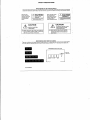
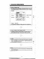
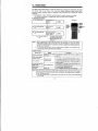
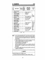
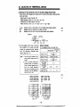
the safetyinstructionlevels
are classifiedinto WARNING" ani
Inthisinstructionmanual,
"CAUTION".
Assumes that incorrect handling may cause hazardous conditions,
resulting in death or severe injury.
Assumes that incorrect handling may cause hazardous conditions,
resulting in medium or slight injury, or may cause physical damage
only.
Note that the CAUTION level may lead to a serious consequence according to conditions.
Please follow the instructions of both levels because they are important to personnel safety.
1
SAFETY INSTRUCTIONS
1. Electric Shock Prevention
WARNING
A
I
A
A
A
,
j
j
While power is on or when the inverter is running, do not open the front cover.
You may get an electric shock.
Do not run the inverter Ath the front cover removed. Otherwise, you may access the
exposed high-voltage terminals and charging parl and get an electric shock.
If power is OH, do not remove the front cover except for wiring or periodic inspection.
You may access the charged inverter circuits and get an electric shock.
Before starting wiring or inspection, wHch power OH, wait for more than 10 minutes,
and check for no residual voltage with a tester.
Use a class 3 or higher earthing method to earth t h e inverter.
Any person who is involved in the wiring or inspection of this equipment should be fully
competent to do the work.
Always install the inverter before wiring. Otherwise, you may get an electrr. shock or be
injured.
Operate the switches with dry hands to prevent an electric shock.
Do not subject the cables to scratches, excessive stress, heavy loads or pinching.
Otherwise. you may get an electric shock.
2. Fire Prevention
I
A
CAUTION
a Mount the inverter and brake resistor on a noncombustible surface. Installing the
inverter directly on or near a combustible surface could lead to a fire.
a If the inverter has become faulty, switch power OH on the inverter's power supply side.
A continuous flow of a large current could cause a fire.
a When using a brake resistor, use a circuit to cut OH the power when an inverter error
a
A
L
I
signal occurs. Failure to do so could cause the brake resistor to abnormally overheat
and a fire to start if a fault occurs in the brake transistor, etc.
Do not connect the resistor directly to the DC terminals P,N. Thls could cause a fire.
3. Injury Prevention
A
'3
f
a CAUTION
Apply only the voltage specified in the instruction manual to each terminal to prevent
damage, etc.
Ensure that the cables are connected to the correct terminals. Otherwise, damage, etc.
may occur.
Always make sure that polarky is correct to prevent damage, etc.
While power is on or for some time after power-off, do not touch the inverter or brake
resistor as these will be not and you may be burned.
4. Additional instructions
To prevent injury, damage, or product failure please note the following
pow.
(1) Transpotation and mounting,
bl CAUTION
h Take care when carrying products, use correct lifting gear.
h Do not slack the inverter boxes higher than the number recommended.
h
h
h
h
h
h
h
Ensure that installation position and material can withstand the weight
of the inverter.
install according to the information in the Instruction Manual.
Do no1 operate a the inverter is damaged or has parts missing.
Do not lift (he inverter with the front cover attached. It may fall off,
Do not stand or rest heavy objects on the inverter.
Check the inverter mounting orientation is correct.
Prevent any dust, wire fragments or other foreign bodies from dropping into the inverter
during wiring up and commissioning.
Do not drop the inverter, or subject it to impacts.
Use the inverter under the following environmental conditions:
Temperatures applicable for a short time, e.g. in transit.
(2) Wiring
d CAUTION
Do not fit capacitive equipment such as power factor correction capacitor, noise filter or
surge suppressor onto the output of the inverter.
The connection orientalion of the output cables U, V, W to the motor will affect the
direction of rotation of the motor.
(3) trial run
A
Check all parameters, and ensure
start-up.
I
.
._
d CAUTION
~~~
that the machine will not be damaged
by sudden
(4) ow-
& When retry
&
&
&
A
&
A
&
A
&
A
d CAUTION
function is selected, the M e r will try to restart the machine up to 10
times over a one hour
Ensure operator safety with other devices.
The stop key is valid only when furrtion setting has been made. Prepare an
emergency stop switch separately.
Switch off the start signal when resetting the inverter. Failure to do so may start the
motor immediateiy after reset.
Do not use for loads other than the $phase induction motor. If another electric device
is connected to the inverter output, the device could be damaged
Do not modify the equipment.
The electronic motor thermal protection does not guarantee lo prevent motor burn out.
Do not use a contactor on the inverter input f o r lrequent startinwstopping of the
inverter, use control signals.
To reduce the effect of mains conducted electromagnetic interference, use a RFI noise
finer. Take care to ensure that electromagnetic radiation from the inverter does not
damage or affect the operation of nearby electrical equipment.
When driving a 400 V class W r with the inverter, use an insulation-enhamed motor,
or measures should be taken to suppress the surge vottage. Surge vonages atributable
to the wiring constant may occur at motor terminals, deterioraling the insulation of the
motor.
When parameter clear or all parameter clear is performed, each parameter returns to
the factory setting. Re-set the requlred parameters before starting operation.
The inverter can be easiiy set for high-speed operatin. W o r e changing its setting,
fully examine the performances of the motor and machine.
The inverter does not have a holding stop facility. For emergency stop, another circuit
must be used.
period.
(5) Emergency stop
A
d CAUTION
Provide a safety backup such as an emergency brake which wiil prevent the machine
and equipment from hazardous conditions if the inverter fails.
(6) Malntenenco, i n o p e d o n and pmta mplacemont
CAUTION
Do not carry out a megger (imulaticm resistance) test on the control circuit of the inverler.
r
(7) Dlsporing of t h e inverter.
~~
Treat as industrial waste.
d
CAUTION
(8) General
[Many of the diagrams and drawings in the instruction manual show the inverter without a
cover, or partially open. Never mn the inverter like this. Always replace the cover and follow this instruction manual when operating the inverter.
A-4
I
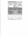
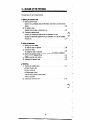
CONTENTS
GUIDELINES FOR HANDLING
1
2
.
.
.
4.
5.
3
6
.
7
.
.
9.
10.
8
.
11
.
12
.
13
.
15.
14
- II -
82
83
. . . . . . . .
..........
--
24.
25.
26.
27.
APPENDICES
Appendix 1. INSTRUCTIONSFOR COMPLIANCE
' ..
'.
APP-1
WITH THE EUROPEAN DIRECTIVES .
Appendix2.INSTRUCTIONS
FOR COMPLIANCE WITH THE UL STANDARD . ' . APP-2
Appendix 3, WARRANTY . . . . . . . . . . .
. . . . . . . . . . . . . . . . . . . . . . . . , . APP-3
, ' ,
,
- iv-
' ,
'
' '
' ' '
1
GUIDELINES FOR HANDLING
Improper handling of an inverler may cause malfunctioning, reduction in service life. or severe
damage.
Handle the Inverter carefully; refer to the description and caution information provided in this
manual.
I
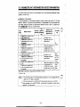
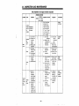
Immmnt
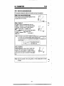
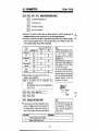
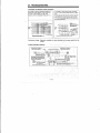
Po*mS"pplY sp.stfiutlon
The power suppb must meet me requirement inverter.
IRefer to:l
p.117
conlador is used, do n o t use il for slanlstop m t r d of me
inverter. If H is used to start or stop me Inverter, it will damage
supply (500 kVA or larger, and wiring distance of IMn
(10.9yards) or shorter) or lor power f a d w improvement,
installath of a reactor (option)is required.
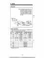
Choose a reactor according to me inverter model:
Installation L d o n
The service Iile of me inverter is influenced by temperature.
Ambient temperature should be held Whin the specified l m i k
p.10
adequate heat dissipation.
The control signal ihnes must be run as far from me main
clrcuit as possible so mat me inverter will not be atfected by
-
If unring distance IS long. check
me following
p.11
I ) Parametem to be set it general-purpose magnebc flux vector
control mode is selected (refer to page 5 3 . )
2) Leak current (refer to page 116.)
.?
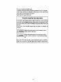
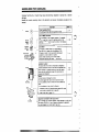
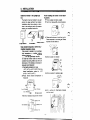
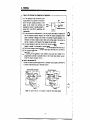
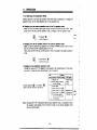
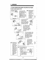
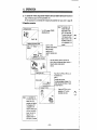
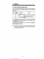
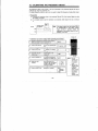
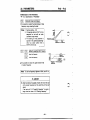
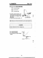
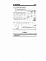
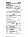
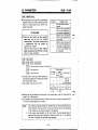
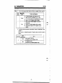
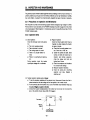
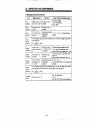
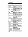
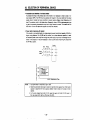
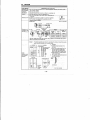
1. PRECAUTIONS
Use ttte inverter within the permissible
Do not attempt Megger test on inverter
ambient temperature range
control circuit
Temperaturehasacriticalinfluence on theserIf insulationreSiStanCe is to be measuredforthe
vice life of the inverter.Ambienttempereturepowersupplylinesandthemotor,eitherdisconmust be controll%d.so thattheinverteris
nect the wire at the inverter terminals or short
operatedwithinthepermissibletemperature
the terminals as shown in the illustration below.
range. ~ t s see
o inverter instakation i n s t ~ t i o n s
.- Inverter
and environment.
{ :?-:A
(Refer to page 10.)
\. '4 P
c
i
Connecting input power to Uw output
twninals of Uw inverter, will drmage
the output transistors.
If power supply vonage is
appliedto terminalsU,
V, and W, the inverter will be damaged. Check
the wiring and operation sequence (commercial
power supply switching, for example) carefully.
a
Power supply
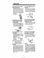
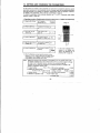
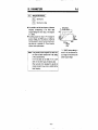
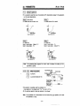
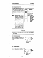
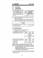
Do not touch the Inside of the inverter
during opemtion
The inverter has hgh vokage circuits. Before attempting inspection inside the inverter, disconand be thatthePOWER
nectpowersupply
i m i n e lamp is
OFF. (also
used
as the charge
indicating lamp)
HOW
P~~~~
;o:
i G G t i n g !amp
+H I#it i n d i t e s
hlgh-voltage
remalns
Ittakesmorethan 60 sec for
discharge of the internal capacitor
after disconnecting power supply.
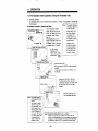
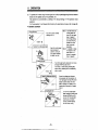
Radio Noiws
The inverter input/ouput circuits (main circuits)
contain high hannonics which may cause interference Lo cnmmunicaticm equipment (AM radio)
b3ing used near the irrverter. If mteriarence occ u m , use a noise f i k r (FR-EIF(-H) option, only
foc i n p r t circuit), or line noise filter (FR-BSFO1
optron)to reduce radio noise. (For details, refer
to page 110 to 116).
Do not use disconnect switch magnetic
contactor at the inverter output to start
or stop the motor (inverter).
If starYstopofthemotor(inverter)
is repeated
frequently, it will cause failureoftheinverter.
Use the start slgnal at the inverter.
ON OFF ON OFF
Power supply -.-
/,ON
UJ
OF&
- ()
Magnetic mntmor A
(MC)
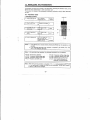
Do not connect PF correction capacttor,
surge suppressor, or radio noise filter
(option, FR-BIF) at the output side.
If any of these equipments
is connected to the
output side of the inverter, it will damage the insupverterordamagethecapacitororsurge
pressor.
Inverter
%jiE!Oml
capadtor
Grounding
Due to hgh-speed switching operation
of the inverter,leakagecurrentwill be increased corn
pared to conventional inverters. Always ground
fhe
the inverter andthe motor. When ~~ounding
invertsr. use the grounding twmiml provided
EstaMisk e low resistawe earlhg m d 8s close
to the drive as possible. Do not connect through
resblsnce
pipe threads, slip joints, or other high
paths to ground.
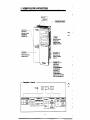
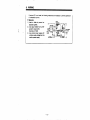
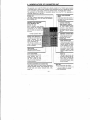
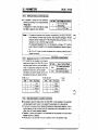
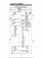
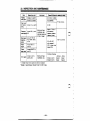
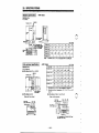
2. NOMENCLATUREANDFUNCTIONS
-
Descrlptlon of I n v W
-2-
.
2. NOMENCLATUREANDFUNCTIONS
m inverter without Front Cover
tor charpe r c h t i n g
lamp lor capadtor)
stitl Mnd and the
h g ~ ~ nS
oornlrq sipnal
t1
T s ~ N I&t
lor
c m n d i o n power
Used lo mnnen the
porn w m and ths
molor, etc. It also has
the terminals tor brake
resbtor.
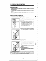
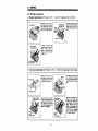
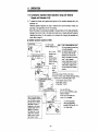
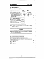
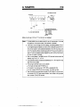
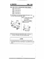
Removing/Attachlng the Front Cover
Removing the front cover
Press down on the latches (2 pcs.) at the top of the front
cover and pull forward.
0
I
I
0
Attaching the front cover
Insert the tabs (2 pcs.) at the bottom of the front cover
into the recesses in the chassis and push the front cover
toward the chassis until the latches engage secureb.
Notes: 1. Alter attaching ttte fmnt c a w , tsst to make sure
that k is securety held in phca by the latches.
2. On inverters equipped with a paramem una. ttte
tnveiler cover can not be removed eaady
became the parameter unit is m
n
e
c
t
e
dthrough
to the chassis.Therelore, h m reroving the
front cover, use caUtion not to damage the
- 3. ..
..
2. NOMENCLATURE AND F W C T W S
rn Parameter Unit Location
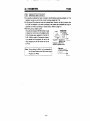
The parameter unit can be mounted directly on the inverter, or installed in a remote location
with an optional cable.
In a remote installation, the parameter unit may be used as a hand-held unit or mounted in an
enclosure.
Removal and installation of the parameter unit is permissible while the inverter is powered up
or in operation.
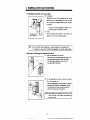
rn Removing and installlng the Parameter Unit
Removing
the
parameter Unn from the Inverter
Theparameterunitisfixedtotheinverterwithclamp
screws. Followthestepsindicated
below to remove it
from the inverter.
(1) Open the cover at the front of the parameter unit.
WMle pressing to the right against thehinge (1)
at the upperleft of the cover, pullthe mver
with the thumb lightly pressingon the lug
(2), at the upper right of the cover.
4
I
I
I
(2) Removetheclamp
screwfrom theparameterunit
Then, remove the parameter unit from the inverter.
Installing the parameter unH on the inverter directly
(1) Connection
Insert the parameter unit connector into the connector in the inverter as shown in the illustration in the
lee.
(Press on the parameter unit to insert the connector
securely.)
(2) Clamping the parameter unit
Clamp the parameter unit to the inverterwiththe
clamp screw.
No(.:
I
rd
,d
c
1
Whar inftailing the p a r a m e t e r unit to the ilverter directly. it must be mounted on the front cover
of Me hvener. Never ircstall it on the inwrter with the lront cover removed.
-4-
.
2. NOMENCLATUREANDFUNCTIONS
Installing the parameter unit using a cabb
( 1 ) Connection
Assemble one end of the connector to the inverter
and other end to the parameter unit. Use the guide
pin and guide slot to determine the correct connector
orientation.
(Forcing the connectors together in W s i t i o n to the
polarizing guides will damage the inverter.)
(2) Fixing
After connecting the connector to the inverter unit,
securely fix It with the mounting screws.
Align m e guide pin
with m e guide slot.
Note: Use the connection cable available as an optional accessory
to the parameter unit.
I1 It is necessary to securely fix the cable to t b parameter unit, use the L-pattern cable.
~
~~~~~
Removing and Attaching the Paremeter Unit Cover
(1) Open the parameter unit cover 9
0
'
While pressing to the right against the hinge (1) at
the upper left of the cover, pull the cover with
the thumb lightly pressing on the lug (2),at
the upper right of t h e cover.
I
I
I
r
(2) Pull the parameter unit cover to the left to remove it
from the parameter unit.
Adjust the parameter unit cover position so that the
slot faces in the direction as illustrated in the left.
The parameter unit cover can be removed only
when the slots are s e t in this position.
Note: Whenattachingtheparameterunacover,
set the
slots in the coverin the direction as illustratedand
push to the right.
2. NOMENCLATURE AND FUNCTIONS
Removing and Attaching the Acc08sory Cover
Insert the tip of a screw driver into the slot at the right side
of the inverter and pull the handle of the screw driver up
around the slot to loosen cover.
Pull the cover toward you to T%moye.
To attach the accessory cover, insert the left edge of the
cover into the slot in the inverter and push the right side
of the cover against the inverter.
Handling th. FFbARW03 Par#rwtr Copy Unk
The FR-ARWOS parameter copy unit can be connected to the inverter directly or with an optional cable. Options, functionsettings, and operation status monitoringm n be done, the same
as with the FR-PUO3. Note that the function assigned to the @ key on the FR-ARW03 differs from that on the FR-PUO3.
With the FR-ARW03 it is possible to read the inverter parameters set for individual applications
collectively and to copy them to other inverters.
Note: 1. Do not copy the parameters between differing voltage classes or differing capacities.
If the parametersare copied between differing voltage classesor differing capacities,
the motorrotation may become unstable, unexpected alarms may occur, or the
inverter‘s performance may be acheved. Contact Mitsubishi if the parameters are
copied by mistake.
2. If copying the parameters from old version to new version, the set value of Pr.31 and
Pr.81 changes. After parameter copy from old version to new version, manually set
“0” to Pr.31 and set ‘9999” to Pr.81 in new version.
Please see the following serial number to distinguish new version. The serial number
is shown on the name plate. New version has the same or higher number.
FR-A024-0.1K lo 1.5K
-6-
2. NOMENCLATURE AND FUNCTIONS
Handling the FR-PUM1 Parameter Unk
The FR-PUO2.1 parameter unit can be connected to the inverler using an optional cable.
Note: With the FR-PUO2.1, setting the inverter parameters. operating frequency, and running
operation for forward and reverse rotation can be done. However, monitoring (including
graphic) and other operations can be done only within a limited range.
If the FR-PUO2.1, is used and Pr. 37 (speed unit) is set to 100 or higher, a value that
ignores the third and above digits, and which also ignores the monitor display will be
applied. (Note that the set value is registered, so il the Pr. 37 s e t value is read with the
FR-PUOS, a value that is set to 100 or higher will display.
-7.
._.
.
~.-
__..
.
.. - .
...
.
.
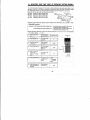
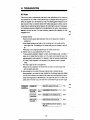
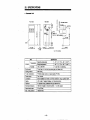
3. PREPARATION BEFORK ,OPERATION
I
-
Applicable motorcapaaty
- Outputrabng
Accassory . lnstnrclionmanual
If any questions arise or &livered product has defects, please contact your Mitsubkhi dealer.
0
2.PreparationofApparatusandComponentsNecessary
lor Operation
The apparatus and components to be used differ depending on the application requirements.
Select the necessary items by referring to the table on page 9 (Operation Control Modes).
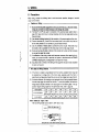
3. Installation
Install the inverter considering location, physical orientation ambient temperature. and atmospheric
conditions.Improperinstallationmayshortenthesetvicelite
or degradetheperformanceofthe
inverter. (see environmental conditions; page 120)
Wiring
4.
Connect the input power, output to the motor, and control signal lines to the terminal block.
cautions on wiring notes; page 11)
-8-
(see
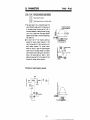
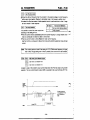
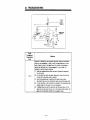
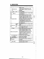
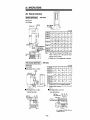
5. INSTALLATION
- " .
..
"
Instnll tho lnwrter in the upright posC
tlon.
The invertermust be installedin an upright
positionto d o w sufficientheatradiation.
Installations other than vertical, or obstructions in the cooling air path, will cause over
heating and reduced service life.
Avoid instaling the inverter in tho following places.
Placessubjecttodirectsunlight.
Humidair(above
90% noncondensing)
fqp g q
0
upw--
X
Flrt lnstsllation
0
sideways Installation
Keep mbknt tempr.hrre within tho p r rniulbb temprrtun nnge.
if the inverter is installed in surroundingsof
hightemperature,orinstalledinside
an
enclosure without adequate cooling the service life will be significantly reduced.
To install the inverter inside an enclosure,
cwgider the coding method as well as the
dimensbns of the eodowre necessary for
adequate heat c#ssipation.
0 Petmlssble temperature range
-1o'C (14'F) to +50'C (122'F) (The fully
closed
specification
product
-1O'C
is
(14'F) to + W C (lM'F).)
Points where ambienttemperature
is
measured
Places with airborne oil mist, dust,or lint.
Places exposed to corrosive gas. Places
sa'air.
exposed lo
laden
Places subject to vibration.
Places exposed to explasive
gas
On a surface of inflammablematerial
such as wood.
@ M e ~ m r pants
q
0
.
b , . ..
1
Minimum clearance around the inverter
1 mmm (3 WlrWmIi DI r a r e
- 10-
.
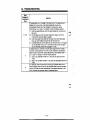
6. WIRING
6.1 Precautions
When wiring, consider the following items to avoid erroneous operation, damage or incorrect
usage to the inverter.
Cautions o n Wiring
(1) Do not connect the power supply wires to the output terminals (U, V, W) 01 the inverter.
If they are connected to these terminals, it will damage the inverter.
(2) Terminals P and PR are used for connection 01 the optional brake resistor (refer to
\
page 131). Never short circuit or connect anything other than the brake resistor across
these terminals.
(3) Use sleeved solderless terminals for the connection of the power supply and the motor.
(4) Common terminals SD, 5, and SE in the terminal block for the control circuit are not
at the same potential. Do not connect or ground these terminals.
(5) Use only shielded or twisted caMes to connect the control circuits. These wires must
be routed as far as possible from the main power and AC relay logic circuits.
(6) During wiring, close the slots on the top of the inverter with a cover so that cut pieces
of wire will not enter the inverter.
(7) If modilkation of the wiring OT other work becomes necessary aiter operating the inverter, do not touch the wire or terminals until power is disconnect and the POWER
CHARGE indicating lamp is extinguished for at least two minutes.
(8) Any p e k o n who is involved in the wiring of this equipment should be fully competent
to carry out the work.
-
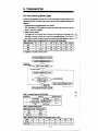
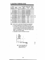
Wire Size and Wiring Distance
(1) If the motor is installed a long distance from the inverter, available motor torque will
be reduced due to voltage drop in the motor cable, especially when the motor is
operating at low frequencies. Select the wire size so that voltage drop is less than 2%.
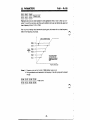
(2) At extreme distances. the charging current generated due to floating capacity between
the wires may trigger the current limit function. To avoid this problem, the maximum
wiring distance should be limited to the values given in the following table. If the application requires wiring longer than the permissible lirnlts, refer to page 55.
-
Note: l m t w (m) Appx. 3 feet
The total wiring length must be 500 m (1641 feet) or less.
lnvener
500m (1MIfeet) or less
IM
lnvelter
3Wm (984.6 feet) + 3oom (984.6 feet)=6OCin (1969.2 1881)
- 11 -
6. WIRING
-
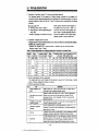
Items to 60 Checked when Designing an Application
JjTFbF
(1) If the application has acommercial power
supply selector circuit as shown in the illustration to the right, accidental connection of line
Power
power to IIMinverter output terminalswill
damage the inverter. To avoid this problem,
in*__._______.
A c d d a a l connection
terlock MC1 and MC2 both electrically and
IWMieI
mechanically.
(2) At an occurrence 01 power interruption, il the start signal (start switch) is retained ON
with the frequency instructionretained, the inverterwillrestart automaticaliy when
power is restored. It restarting of the inverter is not desired on poww restoration, it is
necessary to install a magnetic contactor (MC) at the primary side of the inverter as
well as to design a control sequence that disables the s@rt signal.
(3) Low level signals are used in the control circuit. Use dry contacts, hwo contacts arranged in parallel, or a twincontact to prevent defective wntecting.
(4) Do not input voltage to contact input terminals (STF, for example) of the control circuit,
(5) Do not apply voltage directty to the alarm output signal terminals (A, 8, C ) without a
relay coil or lamp.
(6) If, according tothe ap@cation, an open collectoroutput such as an output from a
programmable controller is connected directly to t h e inverter input terminal, use terminal PC (external transistor common).
How to 0.u trnnirui PC
Connect the external power supply common for tramistor output signals to terminal PC
to prevent malfunctioning due to undesirable current.
*'
Note: For type AY40 unit, it is necessary to install 24 VDC power suppiy.
-12-
..
I
I
.
,
6. WIRING
It temlnal PC isnot used, the follow ing measures are necessary to prevent generation
of undesirable current.
Measures
Insert a diode to preventundesirable c u m t .
Use wtput module having independent output points.
(Example: AY40A)
Use external power supply with
a higher supply voltage than the
inverter power supply.
-13-
6. WIRING
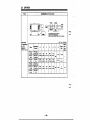
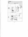
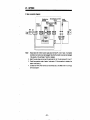
6.2 Connecting the Power Supply and Motor
Termid block
drait breaka
ed
ckm(indcat6dbyenamm)HhenviervedfrcmUwmotor
Brake unit (option)
.?.Do not use the optional brake
Brake resistor
(OPM)
(Refer to page 133)
unit and brake resistor simultaneously.
Uotes: 1. Terminal block (Configuration of the terminal Mock varies depending on the inverter capacity.)
0 Arrangement of terminals . . . .
See theillustrationabove.
Screwsize . . . . . . . . , . . , . . . . M3.5 screws (FR-A024-0.1 K to 1.5K). (FR-AM-
0.4K to 1.5K)
M4 screws (FR-A024-2.2 K. 3.7 K), (FR-AM-2.2K,
3.7K)
Specification of terminals. . , . . Referto'Specifications of Terminals'(page 123).
2.Groundingterminals(Configuration
of theterminal block variesdependingontheinverter
capaclty.)
0 Arrangement of grounding terminals
, , , , . , , , . , . . . . . . , .
Two terminals beneath the terminal block
Screwsize . . . . . . . . . . , . . . . . M3.5 screws (FR-A024-0.1 K to 1.5 K), (FR-AM0.4 K to 1.5 K)
M4 screws (FR-A024-2.2 K, 3.7 K), (FR-AM-2.2K,
3.7 K)
Solderless terminals (If grounding wire is connected using the solderless terminals)
. , , . . , , , . . , . . . . . . . Nominal size 2-3.5 (FR-A024-0.1 K to 1.5 K). (FRAM-0.4 K to 1.5 K)
Nominal size 2-4 (FR-A024-2.2 K, 3.7 K), (FR-AM2.2 K , 3.7 K)
3. Wire sue
Rder to "Selection of Peripheral Devices" (page 128)
-14-
6. WIRING
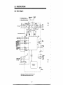
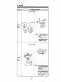
6.3 Connecting the Control Signalr
Frequency meter
This rasblci is rot neceswy
U calbra&xis made using
me parameter unit.
Frequewy sethng
variaMe restor
a2WlM)(Nde4)
I1
I
Notes: 1. Terminal block
Arrangement of terminals .-.Seethe illustration above (in two rows).
Screw size
M3 screws
2. For the terminals indicated by an asterisk (*), input or output specifications may
be changed by changing the setting for the corresponding parameter.
3. Two SD terminals are internally connected.
4. I1 frequency setting must be changed frequently, it is recommended to use 2 W.
1 kR resistor.
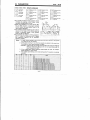
6. WIRING
Power S
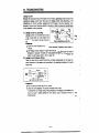
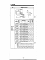
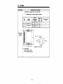
6.4 Operating the Inverter Using Single+-
w
li single-phase power supply is used to operate the inverter only 2/3 of the diodes will be used,
and ripple current of the capacitor will increase compared to operation with three-phase power
supply, resuiting in higher temperature rise of the converter and the capacitor. Operating the inverter using a Single-phase power supply requires derating the output current.
currenr
1.1
2.4
4.5
7.6
11.2
12.9
17.4
W i o n r on operating the Inverter using singlsphasc power supply
(1) Connect the single-phase power suppty to the terminals R arid S of the inverter.
(2) If capacity of the power supply is insufficient, the output voltage will become unstable under
changing load conditions. Therefore, be certain the power supply is adequate.
0
<Example circuit>
-
NFB
Power supply 1 0 AC
mto23ov
Sago Hz
-16-
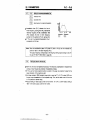
6. WIRING
6.5 Wiring procedures
0
Standard specificatha (FR-A024-0.1K (P)
- 1.5K (P). F R - A W . 4 K (P), 0.75K (P))
J
Mounting screws
1
-17.
.
6. WIRING
Standtlrd ~wlficllti~
(FR-A024-2.2K (P), 3.7K (P), FR-AO44-1.W (P)
- 3.7K (P))
1
Conred t h e a d r d signa
CoMeClionwire tome mlrd
Control wgnal
mMeCllon wire
sgnd terminal block as
s h a m in me drawing.Alter
mnng, r 6 t a H me m x l t cover
Of
me UW.
I
FUlW eneked .p.otfkOtbM
(FR-a4-2.N
e)- C, 3.7K (P) - C, Not iaunctredin Nath k n e r i c a )
Conrmci me ground w e to
me dlreCtwn
ahown in ltm drawing.
t h e U ~ with
I
Power and m t o r
cqnnection wire
c o n t r d signal
I
-18-
I
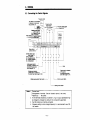
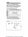
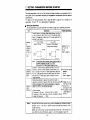
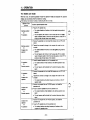
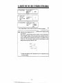
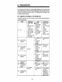
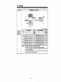
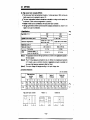
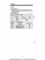
7 . SElTlNG PARAMETERS BEFORE STARTUP
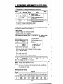
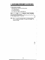
The major parameters to be set, and the functions of these parameters, are explained in the following table. Set the parameters according to the application requirements (load and operation
specifications).
Refer to page 57 lor a complete list of
For details of the setting procedure, refer to page
parameters. The term "Pr." is an abbreviation for parameter.
38.
Setting the parameters
Set the parameters using the parameter unit. Reler lo page 38 lor operating instructions.
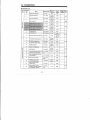
Itern
Selection
of
frequency
reference
slgnal: 0 5 VDC (or)
0 - 10
VDC
Description
Related prarneters
:onnecl frequency refereme vMaga signal W e e n terminals 2
+) and 5 (common). Set Pr.73 for a 5 or 1OV signal as Shown
!elow. (A changeover connector and 10 V power supply are not
rrovided in the inverter.)
_
_
~
0 to 5 VDC
Set r)" in Pr.73 Ifactow
.
.
setting before shipping).
0 to 10 VDC
Set'1"inPr.73
Inverter
Selection for 0 to
5V / 0 to1OV
(Pr.73)
Refer to page 84
010 10
VDC
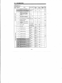
Jote:
Frequency
reference
signal 4 to
20mA
Maximum
output
frequency
If a frequencysettingvariableresistor(potentiometer)is
connected, selection must be '0 to 5 VDC".
Use terminal 10 U internal power supply is used.
:onnect 4 - 20mA reference between terminals 4 (+) and 5
common). Connect a switch between terminals RWAU, and
3D,or a jumper if only the 4 - 20mA signal will be used. Set
'r.74 to 1 ( s e e page 8 4 ) . With the switch closed, the inverter
Hill follow the 4 - 20mA slgnal: open the switch to follow
a
loltaae reference.
jetting this parameter is required only when the inverter is
merated at a maximum freauencv
.
. other than the factory setting.
jetting is necessary if the inverter is operated at a frequency
ligher than 6OHz by an external input signal.
<Factory setting>
D Frequency for 5VInpat ... .60Hz at 5 VDC(Or1OVDC)
D Frequency for 20mA input. OHz at4mADC,and
BOHz at20mP
D Umer limil freauencv
120Hz
Current input signa
selection
(Pr.74)
Refer to page 84
0
Voltage ref., 5Vor
(1OV)input (Pr.38)
Current ref., 4 20mA input (Pr.39)
PUoperatibnmode
Upper frequency
limit (Pr.l)
'
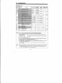
Note: 1. All signal arid low levelcontrolwiringmustbeshielded
type. Shields on signal
wiring (0 - 5V, 0 - IOV. and 4 - 20mA) must be terminated at termiml 5 on the
inverter end only.
Shields on control wiring must be terminated at terminal SD on the inverter end
only. (Refer to wiring information, page 11, and wiring diagram, page 113)
- 19-
7. SElTlNG PARAMSTERS BEPORE B'IXFtTuP
L
r
~
I
L
I
Callk.t*lg the Fmqqurnoy Yan
Calibrate Me frequency meter before statling operation so that the output status can be
monitoredcorrectly. When the parameter unitis
used, the frequency meter canbe
calibrated oreciselv. (Refer 11
If an inverter which has been used before is to be used, the set values 01 the parameters
might have been changed according to a specific operation. Therefore, it is necessary to
initialize the parameter set values before starting the operation. The t e n initialize refers to
the operation to reset the parameter values to the factory-setting values.
The parameter unit can be used to initialize the parameter set values. (Refer to page 39
for details of initialization procdure.)
Remember that the following parameters cannot be initialized by the parameter clearoperation using the parameter unit. For these parameters, change the parameter set value to the
required value after reading the current setting, or reset the parameters to the factory-setting by the aU clear operation.
e Pr.900F
M
' terminal calibration'
Pr.905
"Gain for frequency setting
current"
Pr.902 'Biasfor frequency setting voltage'
Pr.38 "Frequency at 5V (IOV) input"
Pr.903 "Gain for frequency setting voltage'
Pr.39 'Frequency at20mA input"
e Pr.904 g i a s for frequency settingcurrent"
Pr.75 "Resetselectiorddetection of
parameter unit disconnection"
- 20 -
9. PRECAUTIONS ON OP6RATWG THE RARAMHERWCT
~~
~~
~~~~
When operating. the .parameter unit, if review ttm following precautions - - the set value cannot
be writtin or a w m g value is witten.
(1) Plscattionr for operating the in(3) Precautions for operation
verter by the parameter unit
r
-
lnvetter Operation uslng the parameter
unit is enabled only when the [PU OP]
key is pressed or the PU operation or
combination operation mode is selected
by Pr. 79.
In the fobwing cases, theoperation
mode cannot be switched by pressing
the [PU OP] or [EXT OP] key.
(1) While the motor is running.
(2) The external start signal(across
terminals STR or STF, and SD) is
ON.
(3) Thesettingforoperationmode
selection (Pr. 79) is any of the following values.
Setvalue: 1 to 4, 7, 8
If "0" is set for operation mode selection
(Pr. 79),the external operation mode is
established if the following is attempted
- turning off power supplyto the inverter
and then turn it on again, or resetting.
In the monitor mode (MONITORrode
lampis
lit), theoperation
cannot be set.
(blinks)
\+
(unsl)
In the fdbwing c a s e s , jog operation is
not possible.
(1) While the motor is running.
(blinks)
(4) Precautionsfor the number of
digits and a decimal polnt
point
Precautions for monitoring Whileoperating
the motorfromthe
parameter unit,
when
thestartkey
([FWD] or [REV) is pressed after setting the operation frequency, the mode
automticalty switches to themonitor
mode.
-
Themaximumnumber
of digitsfor a
value to be input is 4. It a value is input
exceeding this limit,the most significant
digit is ignored. See the example below.
(MnkS)
To executejogoperation,stop
the
motor first.
(2) If the setting for jog frequency (Pr.
15) islowerthan
the settingfor
operation start frequency (Pr. 13).
- (2)
r
-
Display on
the parameter
1 23 4
s
(input)
-8
-,
i~gnored
(5) Precautions for setting the
operating frequency
-22-
When
the
operation
frequency
has
been set usingthe [A] and p]keys
(step setting) or directly (direct setting),
setting is allowed only in the range established by the upper limit and lower
limit frequencies.
-,
*.
.,
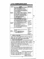
9. PRECAUTIONS ON OPERATING THE PARAMETERUNIT
(6) Cautlons on writing the set values
Writing is possible only in the PU operation mode (Pr.79 = 0, 1).
Inthe external or combined operation
mode, it is not possible to write the set
value. Remember that “reading” is possiMe in any of these operation modes.
However, even in the external or conbination operation mode, writing is possible for the following parameters.
’
Pr.4 to Pr.6
(1) 3-speed setting
(2) Multiple-speed
Pr.24 to Pr.27,
setting . . . . .
Pr.126 toPr.133
(3) Display function . . . Pr.54 to Pr.56
(4) Selection of operation mode Pr.79
(5) FM terminal calibration . . Pr.900
(6) Frequency setting bias and
gain (voltage,
current) . . . . Pr.902 to Pr.905
(7) Key click sound selection . Pr.990
(8) Alarm clear
. . . . . . . . Pr.996
(9) Inverter reset . . . . . . . Pr.997
In the factory-setting status (pr.77 = 0).
writing is not possible while the motor is
running. If writing is attempted in this
status, the error message (Err.) is displayed. However, writing is possible for
the following parameters while the motor
is running.
(1) 3-speed setting ’ ’ ’ Pr.4 to Pr.6
(2) Multiple-speed
....
Pr.24 to Pr.27,
setting
Pr.126 to Pr.133
(3) Tone modulation control
selection . . . . . . . . . . . . . . . Pr.61
(4) PWM frequency selection
Pr.72
(5) Display function ’ Pr.54 to Pr.56
(6) Parameter write disable
selection . . . . . . . . . . Pr.77
. . Pr.900
(7) FM terminal calibration
(8) Frequency setting bias and
gain (voltage,
’
Pr.902 to Pr.905
current)
(9) Key click sound selection ’ . Pr.990
(IO) Alarm clear. . . . . . . . . . . .Pr.996
(1 1) Inverter reset . . . . . . . . . . . .Pr.997
In addition to the cases indicated above,
writing of the set values is disabled in the
following cases as well. If writing is attempted in these cases, the error message (En.) is displayed.
(1) Parameter write disable selection
(Pr.77) is set for ‘disable”.
(2) A parameter number not given in
the parameter list (page 57) is
selected.
(3) A value outside the permissible setting range is set.
(4) A value outside the range established by the upper and lower
limits of frequency (Pr.1 and Pr.2)
is set.
If the error message (Err.) is displayed
when writing is attempted, repeat the
operation from the beginning after pressing the [SET] key.
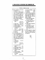
10. W T L W OF THE FUNCTIONS
The parameter unit has the following functions
0
k k c t i n g the operation mcde
External operation rode
Operation using a frequency setting variable resistor, start switch, and other external
devices, . . . . . . . . . . . . . . . . . . . . . . . . . . . . . . . . . . . . . . . . . . . . . . . . . . . . . . . . . . . . .
p.28
PU operation mode
.........................
p.29
operation usingthe keys ontheparameterunit.
Combination operation mode
Operation by combining the external
signals
and
parameter
unit
keys.
U'
Inputting the external start signal while using the parameter unit to set the operating
frequencyetc, . . . . . . . . . . . . . . . . . . . . . . . . . . . . . . . . . . . . . . . . . . . . . .
.
p.31
m
' '
Setting the p M m e t r r
Monltorlng
(1) Checking the operation Status . . . . . . . . . . . . . . . . . . . . . . . . . . . . . . . . . . . . p.41
Output frequency (Hz)
Output current (A)
Rotation speed (dmin)
0 Motor rotating direction (forward, reverse)
0 Motor in-operation
(2)
Checking
the contents of alarm
. . . . . . . p.103
' '
'
''''''''
-24-
'
'
11. OPERATION
11.1 Operation Modes
The operation mode of the inverter is classified into the following three modes - the external
operation mode in whichthe inverter operation is controlledby the external signals, thePU operation mode in which the inverter operation is controlled by the parameter unit, and the combined
operation mode in which the inverter operation is controlled
by boththe externals signals and the
parameter unit.
Factory-set operation mode
Whenpoweristurned
ON or whenthe inverter is reset, the operationmodeis set to
"operation
using
external
input
slgnals".
Therefore, the inverter can be operated using
the external signals whenit is tumed ON. The
inverterstartsoperating
if the startsignal
(STF/STR and SD) is turned ON in this state.
A speed reference signal is also required for
motor rotation.
To fix the operation mode
it is possible to set the operation mode which
is established when power is turned ON. For
example, if the inverter needs to be operated
only in the PU operation mode, it is possible
to set the PU operation mode as the mode to
be estaMished when power is tumed O N . In
this state, there isno needto press the operation mode selection
key
to select the PU
operation
mode
aiter
turning
ON power.
The procedure to set the default mode for the
mode whichisestablished
when power is
turned on is explained on page 27.
t h e p a r a m a m unll.
* Freqwncy IS $91 mth an 0Iternal
d e v m (frequency sen~ngvarlabl
- 25 -
11. OPERATION
11.2 Selecting the Operation Mode
External operation is the lactoly set operation mode when power is switched on. To change the
operation mode, use the mode selection keys on the parameter unit.
Changing from the extanal opmtion mock to the PU operation mod.:
Make sure that the external input signal across terminals STF/STR and SD is OFF. Then,
press the [PU OP] key, and the operation mode IS changed to the PU operation mode.
n
v
e aunnghg from thr w 0pemt.h mO& to the external opemtion mode:
Make sure that the external input signal across terminals STF/STR and SD is OFF, and that
both of the FWD and REV indicating lamps are not lit.
Then, press the [EXT OP] key, and me operation mode is changed to the extemal operation
mode.
-
0
External operatan
;*-
(The EXT OP lamp IS ill.)
Changing to tfm amblnation operation mode:
Change the value set for Pr.79 (operation mode seleclion) as indicaled below. For the procedure used to change the value of parameters, refer to page 38.
T
Contmtr
Operation freqqwncy utting
<&-
Parameter unit
Direct setting, OT
dm [AI VI ks/s.
Teninal SipMk
0 Across 2 and 5: 0 to 5 VDC
0 Across 2 a n d 5: 0 to 10 VDC
Across 4 and 5: 4 to XhM Dc
Multiple-swsd salectlon
(Pr.4 to Pr.6. Pr.24 to PT 27,
Pr.126 to 1 3 3 )
sew
-3c
External operation
PU operation
(Both of the EXT OP'and PU OP are lit.)
I/
1
Note: By Setting "8' f o r Pr.79 (locaVauto external signal selection mode), it is possible to switch
operation mode
the operation mode between the PU operation mode and the extemal
using an external signal.
- 26 -
-.
,,
11. OPERATION
Notes: If the operation mode cannot be changed correctly, check the following items.
1. External input signal
(STF/STR and SD)
I
2. Parameter setting
.....
..... ..
Make sure that the external run command is
OFF. If this is ON, operation mode cannot be
changed.
Check the set value in Pr.79 (operation mode
selection).
8.t VI*.
Dnaiptbn
0
PU operakm and e x l e d operation
(selectable)
(lactwpsethng)
1
W o p e r a m mode only
(changing to other opera(ion W e is
ihpossible.)
2
External operadon mode ollly
(changing lo o-r
operath mode is
i w b l e)
3,4
6
7
Canbinatlor operation mode
Switch over mode
Edlt enable signal mode
Operation mode switchmg is enabled by
a n external signal.
3. Fixing the operation
mode
.....
If the setting for Pr.79 (operation mode selection)
is "0" (factory-setting)
external
operation
the
mode is established when the power is turned
ON. The PU operation mode is selectable by
pressing the [PU OP] key.
With other set values (1 to 8). the operation
mode is fixed according to the set value. Refer to
table above.
11. OPERATION
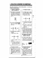
11.3 External Operation Mode (Operation Using External input Signals)
Operation procedure (operation at 60Hz)
-
~l.TunhgONpo*sr-U&bnptJd
qnh
mode .
,
/
openth
Turn ON (he power (POWER
indlcator lam, 18) and make sure
.....
FOWd
,,/
y/ ’
/
’
,
,
-
Fmad
(81,nlcs)
3. A d e r a i o n
Fixed speed
Turn ON the stalt switch (cYosing
the drwif across terminals
STFISTR and SD) (Note 1). The
forward or reversa rotation indication
lamps begin blinking, indicemg that
the mrrespondlng signal is *ut
U
mpjzj
I
b-
mi*
Turn the variable resistor (used for
/ ’ ~
. ’ setting the hequewy) c~o~kwise
/
gradually to the end postion. The
frequency displayed in the display
unlt Increases as me vanable resistor
IS turned and wlll reach M)Hz
(default Values)
Turn the vanable re&@ (used for sening
4. Deceleratkm
the frequency) cwnterckckwlse gradually
to the end position (Note 2). The
frequency displayed in the dlsplay unit
decreasas graduelly as the variable
reslstci is turned and will reach zero
(OHz) (default values)
5. Stopping lbe maor
I,-.
lote 2: If the start switch IS
turned OFF whRe the
variable reslstor is
placed In me righhnost
position, the motor
decelerates and stops.
Almwgh noise due to
hlgh frequency wlll be
generated just before
me stop because DC
injbrakmg is
worktng, this does not
Indicate abnormal
operation.
inverter win n o t operate.
If both of mese
switches are turned ON
during operation, the
motor stops wnnlng
aHer decelerated.
operation m ~ d eby referring to the
procedure given on page 26.
2. Starthg the muor
/’
and reverse switches
are tumed ON, the
that me external operation mode
Indicating lamp is lil. If the
in-ting
lamp is not 111, change
the o w d o n n-c4e to the external
*
,,’ External
,/’
...
OFF
/’
,/’
- ..
Turn OFF the start f w ~ t c h
(openng the drcuit across
teninals STF/STR and SD).
The m o t o r stops Rnning.
For 3 wire m t r d wiih
momentary operation switches
see note 3.
I
Noh 3: The start ~ l g n aselfhdding
l
tunction
can be selected. (For details. see
Pr.59 page 78)
The lnverler wlll Stan when STF
(STR) is Input.
* The operation will continue even
if STF (STR) is rdeesed after that.
To stop release STOP6D with
the stop swllch The inverter wll
stop
- 2a -
F
d
11. OPERATION
11.4 PU Operation Mode (Operation Using the Parameter Unit)
-
(1) Ordinaryoperation
By repeating items 2 and 3 below while the motor is running, it is possible to change the
motor speed.
Operation procedure (operation at 60th)
1 TumgONpnsr--
I
~
/PUoperation
~
,
.. .
# 1
2.S e m g me opsrarion lreqoency
Tum ON the power (POWER
irdicabr lamp lit) ard press lhe
[W OP]key. Makesure that the
W operat!m mode indicating
lenp is lit.
If
indkating lamp is not lit,
chmQe the opemU0n mode to the
PU operation mode by refemng to
the procedure given on page 26.
<Direct operafwn~
.
-.- - Set the operation
frequency at 60HZ.
0 Direct setting (Note 1)
0 Stepsetting
(Note 2)
(Note 3)
.[
Irl
/
,
'
I
3. wrisng IW vabe of hequency
N o b 1: The o p e r a w frequency
is directly s e t using the
n u m k keys Mer
preswng Uw [PU OP]
key. Direct setting is
not possible in the
monitor mode. To set
the operation frequency
d i r d y while the
Inverter is in the
monkor mode, carrsl
the monitor mode by
pressing the [PU OP]
key and s e t the new
Press me [WRITE] key.
Be sure to press R e [WRITE] key after setting the
e is not stored to the memory if it is
4.
Starling the m o r
Press elther h e [FWD] or [REV key.
The m t o r starts runnmgThe mode
automatically changes to the monbr mode
and lhe display unlt gives lhe w@Ut
frequency
5 . Slopping!he motor
-29-
--
-
Press the [STOP]key. me
m t o r decelerates and stops.
11. OPERATION
(2) Jog operation
For the procedure to be followed after changing the parameter set value, refer to page 3 8 .
0 O m t i o n procedure (jog operation at Wz)
T@J
/
/’
/”
I
3. Sewingthe & operation mode
/
,x’
......
4. Operating the M o r
Press Um [PU O P ] key hvo b;mes.
me i ~ opetam
a
mode i~
and
dap4ayed in the display unlt.
..... Press
/
I
-30-
the [FWD] or [REV] key.
‘JOG’
IS
The motor nms while Re key is hehl
pressed and it stops nnning when the key
is releafed.
11. OPERATION
11.5 Combination Operation Mode (Operation Using
Signals and Parameter Unit)
both External
(1) To operate the inverter using external start signals and the operation frequency set by the
parameter unit:
Therefore operation frequency set using an external device and the forward, reverse, and
stop keys on the parameter unit are not functional.
Note: If the forward or reverse key is pressed on the parameter unit, the mode automatically
changes to the monitor mode. In this state, the inverter does not operate although the reverse
indicating lamp blinks. For the procedure to be followed after changing the parameter set
value, refer to page 38.
Operation procedure (operation at 60Hz)
1 ItmwqONpaer
Turn ON
me WWBT
Mote 1: If both ot meSe switches am turned
ON durhg operatbn, (hr mdor stops
running after
NOW 2: The operatbn frequency is direcUy
s e t using the nunelic keys d e r
pressing the [PU OP] key. Direcl
setting is not pcssible in the m
itot
mode. To s e t Itm cpmlion
frequency d i r w while Ihe inverter
IS in Um marfor m o d e . cancel the
monkor mods by pressing Ihe [PU
OP] key and sat the new cgerabon
frequency.
decelera!km.
.
sMch
(closing me
circuit a c r m terminals STF/STR and
1
I==
\
/
L
6 . SbFphg #-amalar
......
SO) (Note 1).
Press the [WRITE] key.
Be sure to Press Ihe [WRITE] key after
11. OPERATION
(2) To operate t h e inverter wmg operation frequency set by 8n Bxtemal device and the start and
stop commands output from the parameter unit:
For the procedure to be followed after changing the parameter set value, refer to page 38.
Operation procedure
1. Tuming ON power
1.
,
,
/
,/
/
POWER
--
2. Selening the operatlon mode
[Sm
MITE]
sgnal ahodd be hput
(STF, STR) are invalid.
The mkn W alsc start
if ttm frequency setting
signal is turned on alter
the [FWD] 01 [REV] key
on
parameler unlt is
pressed.
//”
/’- ’
,
/
Not. 1: The termids in me
hverier M sbrl
- - ..- Turn ONb
l power (POWER
indleAng lamp lit).
79
[READ]
4
......
,/
Set ‘4‘ for R . 7 9
(opefa(ion
Bolh
4. Startlng the motor
[FWD] or [REV]
,
”
Iota 2: In a mode oUmr than
the monitor mode. the
display unit in the
parameter unn displays
me hequeocy which
correspoods to me
frequency setting signal
input from an external
device. Note that this
frequerq is n o t
displayed unless the
[PU OP] key IS pressed.
,/
mode selection)
the external
,.. ...
Press either me [FWD] or (REV] key on
m% parameter unlt.
(Note 1)
The m o r starts nmnmg
me mode auMna(kaRy m
milor mode and the &play
the outprt hequercy
’(6ooo1!
/”
5 . Stopping the m
o
0
l1
s to me
unil glves
...... Press the [STOP] key
STOP
RESET
on me
p a r a m e t e i uW. The r o t o r
decelerates and stops.
I’
I
-32-
n
W
11. OPERATION
~~~
~
~~
~~~~~
~~~
(3) To operate the inverter using the start signal and multiple-speedsignal input from an external
device and the speeds set by the parameter unit:
The operation is accomplished by a setting of "0"(factory-setting) in Pr.79 (operation mode
selection).
For the procedure 'to be followed after changing the parameter set value. refer to page 38.
0 Operation procedure
power ( W W E R
i n d i t i n g lamp lit).
. ---Turn ON the
I
/
/
F
2. Selecting t h e rnuniple-speed slgnal . . .
Hlgh speed
Middle speed
Low r m e d
Select the rnultiple.speed
signal necessary for
operatlon (closing the
drcuit ea068 temsinals
RWRWRL and SD).
I
N~
r e v e m 6 w W - a ~are
turned ON, Uw inwrler
does rot operate. ll
both of meSe swilches
1: dstops
iisx bpossiMe
rnrnring
a b m loaner
change
me frequency for the
speed which is not
s e l e c t e d t o r operahon.
(Reter to page 64.)
Turn OFF (he multiple-speed
(openinp (he drwn a c w
terminals RWRhURL and SD)
and turn OFF (he start sdtd~
(opening me arc& BMSS
terminals STFBTR end SD).
me m t w stops nnning.
11. OPERATION
11.6 Switch over mode
i
With this mode, the external operation rode, PU operation mode and computer link operation
modes can be entered while the inverter is running.
The (OHOwing mcde transNm func(ions are vscd dwinp the W h over rode.
~~
Operation mode
trahsaion
Transition operatidoperation state
0
External operation
8
PU operation
@
External operation
0
4
computer link
wration
PU operation
0
4
External operation
PU operation
0
4
Comprter Link
operation
.
0
Computer link
operation
4
External owration
Computer link
operation
-
1
PU operation
Press the PUoperationkey.
The rotation dLection will a n t i e to be that appked during external
operation.
The set frequency wil continue to be the value set with the v a M
resistor (frequency setter). (Note that once the power is turned OFF or
inverter is reset. mat set value wil be cleamd.)
Remove the parameter unit, and install the computer link unit FR-CU03
(option).
Transmit the command to change to the computer link mode from the
computer.
The rotation dirsdion wil continue to be that applied during external
operation.
The set frequency will mnenue to be the vakre set with the variable
resistor (frequeocy setter). (Nde that once the power is turned OFF or
inverter is reset that set value will be cleared.)
Press the external operation key on the parameter unit.
The rotation direction will be decided by the external operation input
signal.
The set frequency wil be decided by the external frequency setting
signal.
Remove the parameter unit, and install the computerlinkunitFR-CUO3
(optW.
Transmit the command to change lo the cwnputer link mode from the
computer.
The rotation direction and setting frequency wil continue in the PU
operation state.
Remove the computer link unit FFI-CUO3 (option), and install the
parameter unit
Press the external operebon key on the parameter unrt.
The rotation direction wil be decidnd by the external operation input
signal.
The set frequancy wil be decided by the external frequency setting
siand.
Remove the computer link unit FR-CUO3 (option), and install the
parameter unit.
Press the PU operation key on the parameter unit.
The rotation direction and setting frequency will continue in the
computer link operation state.
@
0
0
-34-
3
w'
11. OPERATION
11.7 Edit Enable Signal Mode
Usually, the operation mode should be changed to the PU operation mode when changing the
set value for parameters. In the edit enable sigml mode, changing the values set in parameters
is enabled and disabled by turning ON and OFF the external signal input to the terminal MRS/RT
and SD.
0 In the odlt enable signal mo&, ths following functkns am available.
F>
...
The functions and operation accordingto ONOFF status of the externalsignal (terminal MRSBT)
are summarized below.
Mation
Mode
stop
PU
Running
Twrninais
MRS M d SD
Connected
I
Discmected
Mod.
Switching
Forcibly
switched lo the
extemal
operam mode.
Stlhn
0 UnsmtchaMe
to the
Remains stopped
(Note I )
Forubtf
switched lo the
I
external
Disconnected o
peram m o d e .
Cwected
(Note 1)
If the frequency setting
and start signe.ls d
external operation are
m, operation is
perfwmed accordingly
Remains stopped
Disable
(Note 2)
DisaMe
Note 2. Limited to
parameters h l may
be rewrittendunng
operation.
0 SwitchaMe to Ihe PU
operation mode.
Note 3:
stopped
output
0 UnswNcheble to
Running
8
output stop
the
"p""
eunswitto the
pu operam mode.
Disable
0 Switchable to h e PU
Disable
I
Disable
-35-
o p e r a m mode.
Me4: If the
lreguency setting
SigMlkon,
-tion
is
Pec(0mad -%I)
11. OPERATION
Note: 1 After turningON the MRS terminal, if the setting forPr.79 is changed to any value other
than '7" in the PU operation mode, the MRS terminal functions as the ordinary MRS
terminal (mechanical reset terminal) insteadof the edit enable signal terminal.Then the
operation mode is changed according to the new setting for Pr.79.
2 When mode changed is attempted between the external operation mode to the PU
operation mode with the MRS terminal ON,the mode change will not occur if the STF
or STR terminal is ON.
3 In the settingof Pr.79 = 7 with the MRS terminal ON,if the MRS terminal is turned OFF
while in the PU operation mode, the operation mode is changed to the external operation mode independent of the OWOFF status of the terminal (STF, STR). Therefore, if
the MRS terminal is turned OFF while either the STF or STR terminal IS ON,the motor
is controlled in the external operation mode.
4 During the operation in the PU operation mode, the ordinary MRS function does not
work.
PU operationmodetotheexternaloperation
5 Whenthe mode ischangedfromthe
mode forcibly, the parameter unit is internally reset once to secure the monitor screen.
6 If an alarm has occurred, the inverter can be reset by pressing the stop key in the PU
operation mode. Resetting of the inverterin the external operation mode is not possible.
Therefore, resetting the inverter always changes the mode to the PU operation mode.
-36-
11. OPERATION
11.8 LocaVAuto External Signal Selection Mode
In this mode, the operation mode can
be modified by turning ON/OFF an external signal (terminal
RH). Since the operationmode can be changed by the external signal, erroneous mode switching
can be avoided.
I
Set
value
~
8
1
Signal
(RH and SD)
Close
Open
I
Flxsd mode
External operatm
mode
PU operation mode
1
Comment
Changing to the PU operation mode is impossible.
Changing to the external operation mode is
I
impo~ible,
If the circuk a c w terminals RH and SD is closed while in the PU operation mode, the operation
mode is forcibly changed to the external operation mode. If it is opened, the operation mode is
forcibly changed to the PU operation mode.
Note that this mode change is possible only while the inverter is stopped. The mode change is
not allowed while the inverter is operating.
Note: If '8' is set for Pr.79, the function of the terminal RH (multiple speed setting (high-speed))
is changed to the locaVauto external selection function. In this setting, the ordinary function of the terminal RH does not work.
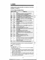
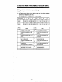
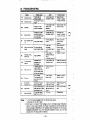
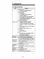
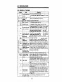
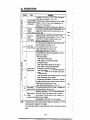
15. ERRORS
If a failwe occurs within the inverter dwing operation, t h e corresponding error code is automatically disprayed in the parameter unit.
15.1 Error Codes and Contents of Errors
f. bf
E BE
E OHT
pf
E PE
fmf
f ,
[.&E
E PUE The
E.CPU
E CPU
frff
cF
f ,
f,GPf
E RET
E
E OPT
Faun of the brake transistor in the inverter was detected.
h e x t d day WBS tripped. which was c m w t to drive by c m t m r .
Fault ol
mmwy device h Ihe invetter where (he parameter deta is sivred CPU
defecrive.
parameter unit was disconnected from the inverter.
Restarting was not possible wimin the set number of retries.
Run-away of he CPU.
If a ground lault current has flown due to a ground lault occurring in tha output ( b e d )
side 01 me inverter. this tunctim stops UM inverter output. A ground IauR occurring at
low w
n
d resistance may activale me overanent protection ( E 1 lo OC3).
Probidmi o
lr the 4M)V class mly.
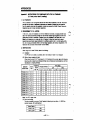
The number of retnes has besn exceeded dunng computer communication."
N o w The ETHM error occurs if current 150% 01 the current s e t for the electronic thermal relay (R.9) flowed
the n w b r over nn extended p
ew d bme.
Ex-
II 'SA' IS set lor Pr.9 (electronic thermal relay).
5(A) x 150(%) = 7.5(%)
The protecoive Iuncthn is acbvated by a current below 7.5A. due to the 1'1 (hlnverse time mp) charwleristic
d me buin-in electrmk thermal relay circuit.
(*)
(")
This error is displayed inthe emergency stop status established by selectingthe PU STOP
key function in external operation is slopped
by pressing this stop key during external
operation and pressing the stop key.
When using the option FR-CU03, this error will display on the following condition: during
of communication
error from exceeded retries during communication, exceeded interval
time; retry execution during normal operation.
-42-
15. ERRORS
Other dirpiay
Dbphy
[&'f
-
Enor coda
E OPT
Conwnb of m o r
When the retry function k s e l e c t e d . reby is executea if the correJpondnp kw"
d a m occurs. This message is displayed while retry is execrded.
The display IS given for the penod s e t by Pr.68 (reby exscuUon waWq W).
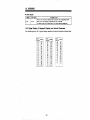
15.2 Digital Display (7-Segment Dlsplay) and Actual Characters
The indication given by the 7-segment display represents the actual characters as shown below.
- 43 -
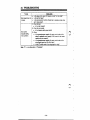
16. PARAMETER UNIT DISCONNECTION DETECTIW FUNCTION
This function detects disconnection of the parameter unit from the inverter and stops the inverter
operation (inverter error).
Operation of the function
To use the parameter unit disconnection detection function, set the proper value for Pr.75 (reset
selection / detection of parameter unit disconnection). If the parameter unit is disconnected from
the inverter, while the parameter unit disconnection detection function is valid, it is detected and
t h e drivq P69().[~rm
stop due to inverter error).
PU STOP
key
h
a
e
l conditions
No
function
)ssIbIe atany
Reset input is possible only
when
protection
17
the function
is adivaled
0 Yes,
3
X*
0
When the parameter
unit
is disconnected, the
ALARMLEDis lil and
inverter output is shut OH
When
stop key
on PU is
pressed
in any
operation
mode,
motor
a+.
x : No
Notes 1: The stop key function is not activated with set values 0 io 3; it is actuated with set
values 14 to 17 (Refer to page 84).
2: The error display at an occurrence of PU disconnection alarm stop is 'E.PUE".
When parameter unit model FR-PUOPE.1 is used, reset is possible by inverter reset
operation in the help mode.
- 46 -
rc
i j
16. PARAMETER UNIT DISCONNECTION DETECTION FUNCTION
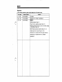
Cautions on setting iha parameter unR disconnection detecictlon function:
(1) If the parameter unit is not connected at the start of operation, an alarm does not occur.
(2) This function recognizes "disconnection" when the parameter unit is disconnected for more
than 1 second.
(3) To restart the inverter operation after the occurrence of the disconnection alarm, confirm the
connection of the parameter unit and reset the inverter. (refer to page 48)
(4) If the inverter is operated without selecting the parameter unit disconnection detection functlon, inverter operation is continued even after the parameter unit is disconnected from the
inverter, which will create a hazardous situation. Therefore, to ensure safe operation, it is
recommended that the parameter unit disconnection detection function be selected.
-47-
.-
,.
19. ADJUSTING “BIAS” AND “GAIN” OF FREQUENCY SETTING SIGNALS
(8) Press
me [READ] key
The w m n t s e w Is
asplawnme
60RO
display unit.
(9)
Input ‘50” using me
numenc keys
Apply a 5 V vdtage
value.
(10) Press me [WRITE) key
I
‘50’ appears in me
53
display unit.
1
The newly set value
is stored to the
m e w
SOAW
I%;%:yI
PW
* If input voltage difference for bias and gain is less than 5%, drive will not accept the values.
Note: Adjust bias and gain by applying 5V (IOV) across terminals 2 and 5 (frequency setting
input terminals).
While voltage is applied across these terminals, frequency is output corresponding to
the input voltage. For example, if the bias and gain are set as explained, output frequency is obtained as shown by the graph (solid line) below if 1V is applied across terminals 2 and 5. When current input is used to control the output frequency, a similar
setting should be made using Pr.904 and Pr.905.
*’
* To adjust output frequency to OHz in response the input of 1V, change the bias using
the same procedure.
-.
.
20. CONTROLLING KEY CLICK SOUND (TACTILE FEED BACK)
With the model FR-PUO3 parameter unit, a key click sound can be added to confirm complete
execution of key stroke. To output key click sound, follow the procedure below.
Pr.990 is factory set to 0 for no key click sound.
.To change the setting to With key click sound", set '1" in Pr.990.
Noto: To set 'nokeyclock
d
1
sound' again, set Pr. 990 to "0" (factory- setting).
4
4
- 52 -
ve
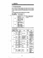
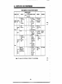
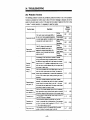
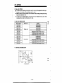
21. SELECTING GENERAL-PURPOSE MAGNETIC FLUX VECTOR CONTROL
The general-purpose magnetic flux vector control can be selected by setting the motor capacity
and type of motor.
The general-purpose magneticflux vector control is effective for applications where greater starting torque or more than V F mode torque at low speed is required. or the load is varying.
(1) Conditions for selecting the general-purpose magnetic flux vector control
The general-purpose magnetic flux vector control can be effectively used only when the foilowing conditions are satisfied.If the general-purpose magneticflux vector control is selected
while any of these conditions is not satisfied,
it will cause insufficient torque, irregular rotation,
and other problems. In which c a s e , V F control should be selected.
Conditions
*The motor capacity is either equivalent to or *The number of poles is 2, 4, or 6. (It is not
one rankbelowtheinvertercapacity.necessarytosetthenumber
of poles. For
*The motor type is Mitsubishi standard
motor
constant torque motors, 4 poles only)
(0.1 kW (1/8HP) or larger, 200V class; *The motor is controlled by its own inverter.
0.2kW (1/4HP) or larger 400V class), MitOWinng distance between the motor and the
If the dissubishlconstanttorque
motor (SF-JRC,
inverter is within 30m (98.46 feet).
200V class, 4 poles, 0.4 (1/2HP) to 3.7kW
tanceexceeds30m(98.46feet),referto
MITSUBISHI.
(5HP)) or MlTSUBlSHl equivalent.
(2) Selecting the general-purpose magnetic flux vector control ... Set the motor capacity (other
than “9999”; “9999” calls for the V/F control.) for Pr.80 (motor capacity). If a Mitsubishi constant torque motor is used, set‘1” for Pr.71 (applicable motor).
Note: Cautlonr on general-purpose magnetk flux vector control
(1) Irregular rotation of the motor will be a little more apparent than in the V/F control.
(2) At the start, 0.1 to 0.2 second delay is generated due to control data calculation.
(3) If this control is selected, the following parameter settings will be ignored. (Pr.0,
Pr.3,
Pr.14, Pr.19, Pr.46,Pr.47)
torque
Applications for which the general-purpose magnetic flux vector control is recommended
*The machinewhichrequiresgreaterstart*The machineinwhichtorquevariationis
ing
*The machine which requires more than V/F
mode torque at low-speed.
(This control is not recommendedfor machines, such as grinders and lapping machines, which
requires low irregularity at speed control at low-speed operation.)
-53-
.
..
..
21. S W C T l N 6 GENERAL-PURPOSE " T I C
.~...
- .2-..
-... .
. .
FLUX VECTOR CONTROL
-
~
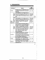
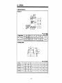
(3) Parameters related to the general-purpose magnetic flux vector control
"\"
Name
80
,
~ . t ( l n grange
0.1 (1/8HP) to
3.7KW (5HP).
capanty
9999'2
Applwe
rotors"
01
s t va~ue
Bgss
Dosulption
selecllon Of vF
amI'd
S W r d rotor
(NEMA B
Setting 01 motor capaaty (kW)
(Selecbon d QmeraCprrposemsgneR
Rux vector m ~ d )
0.1 to 3.7.'
0
1
TEFC M ODP)
Constant torque motor (separataly coded)
F.*wy-
wmne0
0
-
'1. The electronic thermal relay characteristics are selected.
'2. A 0.1 kW setting cannot be made for the 400 V class.
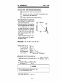
Settlng methods for when general-purpose flux vector control is selected and wiring distance between inverter and motor exceeds 30 rn
1. setting procedura
(1) Calculate the setting values of the special parameter.
Calculate the setting value as shown below.
WMng resistance value(resistance (w) per 1 m 6 wiringlength (m))] (A calculationexample
is shown below.)
<Reference values>
For special wire sizes,
I
'
the following equation is used.
R ( R ) = p x1z
i
t(2)Specialparametersettingmethod
0.004926 R
3.5
constant 1.7241 x 10.'
A: cross-section area
1: length
D:
Set the value obtained in section (1) above with the following procedure.
0 Pr.77:Set to 801(Note 2)
0 Pr. 80:Set motorcapacity
0 Pr. 87: Set resistancevalue
0 Pr. 77: Set to 0 or 1 (Return to oriainal settina value)
Note: Pr. 87 is displayed onlywhen Pr. 77 is set to 801.
(Note 1) The torque may not be achieved if not set.
(Note 2) WhenPr.77is
set to 801,the parametersfollowingPr.82willdisplaysimulbe damaged
taneously, butdo not change the other parameters. The inverter could
if the parameters are changed.
S e t t l n q value calculatlon examples
Wlre S h
(mm2)
.
2
20m
(65.64 feel)
0.171~
3.5
5.5
0.065R
o 09w
30m
(96.46 leet)
0.257~
0.148n
0 097i2
Wlrlng length
8Om
1OOm
150m
2OOm
(262.46 feet) (164.04
(328.08
leet)
feet) (492.12 (eel) (656.16 feet)
0 . 4 2 ~
o.wn
0.857~
1.266~
1.715~
0.24.511
0 . 3 ~ ~
o 7 3 w 0 . 409. 9~ 81 5 ~
0.162fl
O.26OR
0.325R
0 487P
0.65oR
5om
-54-
21. SELECTING GENERAL-PURPOSE MAGNETIC FLUX VECTOR CONTROL
!Setting wthod when wlrlng dlstance
Is particularly long
1. !Setting procedure
( 1 ) If themaximumwiringdistanceislongerthanthevaluesgivenin
the followingtable,set
parameter 98 to invalidate the current limits.
(The factorysettingis 'O", but settingthis to '8" is recommended.)
Operafion
Low.Noise
Operation
(656.4 feet) (656.4 feet) ( W . 6 feel) (1641 feel)
teet) (1641 feel)(1641
(1641 feet)
I I W1 3m0 0 m
1%
I 5 ~ m
1500m
1 5 ~ m
(9846 feel) (3282 teel) (656.4 teel) (964.6 feel) (1641 feel) (1641 feel) (1641 feet)
1%
-55-
..
(2) Special parametersettingprocedure
Set the setting value in (1) above with the following procedure.
0 Pr. 77: Setto 801 (Note 1)
@ Pr. 98: Set the setting value
0 Pr. 77: Set to 0 or 1 (Return to original setting value)
ULbl
ga I
Hm
c u r r e n t linnt, s t a l l prevention tvlction
*: Pr. 98 is displayed only when Pr.
j
I
Sttlng rang.
0
- 15
]
~ h vdue
.
1
1 F-
~
n
0
77 is set to 801,
(Nota 1) When Pr. 77 is set to 801, the parameters following Pr. 82 will display simuitaneously,
butdonotchangetheotherparameters.Theinvertercould
parameters are changed.
be damaged if the
g
9
w
#
*
-56-
. . .
. ..
~
22. PARAMETERS
Pr.0
- Pr.2
H Description of the Parameters
‘Pr,’ in an abbreviation of “Parameter.”
&tung the o
lr
q
u
a booat ( m m u l )
0
ti is possible to adjust the motor torque in thelow
frequency range meeting the load.
Notw 1: Factory-setting ... 6%
2: Change the setting to ‘4%’ for motors
use with an inverter
designedlor
(constant torque motor).
3: Thesettinglorthisparameteris
ignored if the general-purpose mag
netic
flux
vector control
mode
is
selected with Pr.80.
It is possible to clamp the upper and lower limits
of output frequency.
Note.: To set the frequency higher than 120H2, use Pr.18.
A CAUTION
L?I Note that without the speed command, the motor will start
at the prsset frequency by mereiy switching on the start
signal.
If set value of Pr.2 “Lower limit frequency“ is equal or
larger than the value of Pr.13 “Starting frequency‘.
-62-
n .
u’
22. PARAMETERS
Pr.3
It is possible to setthe base frequency (reference
to the
motor
rated
lrequency
corresponding
torque) meeting the motor rating, in the range of
0 to 4 o o t l Z .
fre(base
Pr.19
for
value
the
setting
proper
By
quency voltage), the PWM output is modified so
that the waveforml w k s to the motor like the voltage value set in parameter 19. This will result in
optimum motor performance.
Note: If the general purpose magnetic flux vector control mode has been selected with Pr.80, setting
of Pr.3 becomes 60HZ.
If Pr.19hasbeen set at '9999", Pr.19 = 220V
(44OV for the 400V type) will become valid.
When using the motor designed for use with an
inverter (constant torque motor),set 60Hz for the
base frequency.
-63"
setting r a n g e d
m
j
.
,
Be90
1 W - W
,
B
E
a
S
e
frww
-r
voltage
*: If '9998" (factory-setting)is
set for Pr.19, the maximum output voltage is the same as the
power supply vdtage.
.
.
.. - .
,,
,
.,,
- Pr.9
22.Pr.7
PARAMETERS
Acceleration time (Pr.7) indicates the time in
which frequency, starting from OHz, reaches the
reference frequency (Pr.20). Deceleration time
(Pr.8) indicates the time in which frequency,
starting from the setting for Pr.20, reaches OHz.
If "0" is set for accelerationfdeceleration time, it
corresponds to 0.04 sec.
Note: When the acceleration pattern is S-pattern A (refer to Pr.29), the time indicates the
period to reach to the base frequency (Pr.3).
The output frequency corresponding to the frequency setting signal (analog) is set wlth
the gain (Pr.903, Pr.905) (Refer to page 92.).
-e
Set Pr.9 to the motor nameplate full load amps. The electronic compensation for reduced motor
cooling at lower frequencies protection characteristics include.
0 If "0" is set, the motor protection function is invalid. In this case, the protection function for the
output transistor of the inverter is valid.
0 If a blower cooled or TENV constant torque motor IS used, set '1" in Pr.71 to select 100% continuous torque characteristics in the low-speed range. Then, set the rated current of the motor
in Pr.9 (electronic thermal relay).
0 Factory-setting is "rated output current of the inverter". For 0 . l K to 0.75K models, setting is
"85%" of the rated output current of the inverter.
-65 .
22.’PARAMETERS
wl
-1
a
0
Pr.W
Adjusting tha DC hi.oam br*dng
DC injection bralung time
DC
ifjection brsking vdlage
age. braking tlm, and the frequency at whkh
braking, applied.
DC dynamic braking voltage (factoly-setting) ... 6%
mi~l~~T~n-n~m
~
T
T
Install a mechanical brake. There is no stopping toque.
IR13]
0
-;
m
When using an inverter duty motor (constant toque motor) change the setting to 4%.
A CAUTlON
A
Pr.13
Dc injection braking lrequency
It is possiMe to adjust the “positioning on stop’
control by setting the DC injection braking volt-
I Note:
-
I
~
~
.
1
w n g tha s ~ n f gq t m c y
The starting frequency can be a t in the range of
0 to 60HZ.
:
~
-66-
i
,
W
F~ancrmnO
mwM
~
22. PARAMETERS
Pr.14
- Pr.16
s*ctinp th..ppl*d M
is possible to select the output characteristics (V/F characteristics) proper for the application
and the load characteristics.
0 It
-1
f
For -MI
(factory-setting)
lwque load IWVeprs,
r - 1
-1
For varllble ioque load (fans. p m p s )
t
Note: If thegeneral-purposemagnetic
parameter is ignored.
IKI
I
.
flux control mode is selected, the setting for this
smingth.jogoprnfon
JOS frequency
~ o ga c c e l e r a m * r a m
operation b possible using the parameter unit.
3
"
or '4" is set for Pr.79.)
(Jog operation is not allowed when '
0 In the external operation mode, jog operation is not allowed.
0 Jog
Note: If t h e parameter unit is disconnected from the inverter during jog
will decelerate to a stop.
-67-
operatin, the inverter
22, PARAWTERS
Pr.17
Th.e
function allocated toterminal
RUOH is
switched according to the setting of "0" or "1" for
Pr.17.
R L Low-speed operationselectionsignal
OH: For inputting the contact signal of the thermal
. overloadrelay,installedoutsidetheinverter,
or that of thethermalsensor
built inthe
motor. (N.C. contact)
- Pr.20
'r*id&eor
(IaQoly-semng)
Tlm-md M Y
SD
~
,-?
N o t e : I1 '1' is set in Pr.17, the inverter is expecting a thermal relay N.C, signal. RL is not active with Pr.17 equal to "Im.
A
A
CAUTION
With the external thermal relay connected,do not switch Pr.17 setting to "0". Otherwise, the
motor will be s!erted by the start signal only.
setting the uppr llmh frequency lor hlgh s p u d operation
this frequency value if operation is at a frequency higher than 120Hz.
0 By setting the frequency
for this parameter,the value set lor Pr.1 (upperlimit frequency) is automatically replaced with this setting.
.Set
D
h f e r to ~ r . 3 .
u
Rehr to Pr.7.
?,
d
-68-
- Pr.27
Pr.22
PARAMETERS
22.
lPrpl
IPr66]
S.ningth.rclllpnv.miontunctlonopMUon
bwf
sw m e n t i o n f ~ n c b ~q
w
n a
h lev4 ( a r r e n t Hrnh operatio0 level)
SWI prevenhon u
IMoperation l e v e l Onset coemdent for dwble-sped operat& ( c u r r e n t
limit level reductlcn rateoffset metfidsni at 400 H z )
Frequency for sal1 prevention function level reduction start frequency
Set the stall prevention functlon operation level
(current limit level) for Pr.22. Usually, the setting
should be 150% (factory-setting).
If the motor is controlled to run at a speed faster
than 60 Hz, there are cases when themdor cannot be accelerated because motor current does
it is
possible to
not
increase.
For
such
cases,
reduce the current limit level in the high frequency range to improve the motor operation characteristis. Usually, initial setting is Pr.66 = 60 Hz,
Pr.23 = 100%.
0 If ‘9999” (factorysetting) is set for Pr.23, the current limit level which is set for Pr.22 is applied to
the range up to 400 Hz.
If
apr
hM
Setting example: Pr. 22 = 150%, Pr.23 = 100%. Pr.66 = 60 Hz
Note: The setting value of
Pr. 22 can not be
changed during operationeven il Pr. 77 is
set to 2 (writing during
operation enabled).
Calculating the current limit function operation level
-..
CalCUlating the current limit function operation level
I
where,
Pr.66 (Hz) x Pr.22(%)
A=
output frequency (HZ)
=A +Bx
Pr.66 (Hz) x Pr.22(%)
400 (Hz)
= ~-
d
CAUTION
Do not set the stall preventlon operation level too small.
If set so, torque generated will reduce.
=
Refer to ~ r . 4 .
-69-
I
Pr.29
.The
acceleration/deceleration pattern
p*
gfIf
can be selected according to t h e epplicetin.
o ( h r accekratiod'decderotion paw)I
This is the general acceleratioddecelertion panem and the motor
b usually operated with this setting.
M n g : 1 (S-pattemA ) ]
This pattem is used for the apphcatiw which require quick
acceleration or deceleration in the high speed range (over WHz).
In this pattern, W (base frequency)
is
taken
as the
point of
inHeUion. Using thk pattern, it is p o m e to set ths
accekrtioddeceleration time which Ms the motor toque reduction
in the constant Hf output operation range over WHz.
llw pattern is applicable to controlling the spindle speed of
machine tools.
gh
ai
..........
rm
b
...
*
nim
A
I
Mote: For the value to be set, use the time necessary lor acceleration up to
the base lrequencyW
(Pr.3) instead of the acceleratiorddeceleratim rderence lrequency (Pr.20).
The actual acceleration time11' seconds beyond the base frequency "W is calculated bythe
following formula.
I
Setting: 2 (S-pattern B)
Acceleratiorddeceieration is atways controlled in S-pattem withtn
the range of 72' (current Irequency) to "ll' (target frequency).
Therefore, shock during acceleration and decelration is minimized
and this control can be used to prevent loads from being toppled
over.
r-
Note: Even if this parameter is written during operation, it will be validated after the inverter
is StODDed.
-70-
A
.
.
I..
I
... .
22. PARAMETERS
F
l
Pr.30
Salting the regenantive b n b duly ntlo
Selechng me regenerative brake duiy rafio
Setting me spwal regenerative brake duty r a m
0 These
parameters should be set when regenerative
brake is used frequently due to frequent starts and
stop. In this case, since the brake resistor capacity
must be increased, it is necessary to use an optional
high-frequency brake resistor (Note 4).
0 Setting method: After setting ‘1“ for Pr.30 (changing
the duty ratio), set the duty ratio (Note 1) for Pr.70.
M-I
setting
range for
%“:&o
fr
Pr.70
0
FR.A024/
AM-0.4K
to 3.7K
(factory-
(Note 2)
’
0 to 30%
(note 3)
=ning)
(factorysetting: 0%)
2. If Pr.30 = 0, Pr.70 isnot displayed. If Pr.30 = 0, the brake duty will be 3 %
3. If the set value for Pr.70 should be increased, the value must be smaller than the
permissible brake duty ratlo (refer to page 94) of the external brake resistor. (MRS
or FR-ABR)
4. Brake resistor cannot be connected to 0.1 K and 0.2K. Because they have no brake
transistor.
A
d
CAUTION
Do not set the brake duty above the permissible value of the brake resistor used, otherwise,
overheating may occur.
- 71 -
.. .
as.
PARAMETERS
Pr.31
- Pr.36
*These Parameters are for Communication Option CU03.
ll C W 3 is not used, do not change the Factory setting of these Parameters.
For information on setting value, refer to CU03 manual.
1
-72-
22. PARAMETERS
IPr371 S M n g th.
Pr.37
- Pr.39
d*muntt'
It is possible to display the load speed such as a
conveyor, instead of the motor. For this display,
it is necessary to set the unit of display which
meets the load's speed using the parameter unit.
0 Setting should be made for the load's speed at
MHz.
0
Display is given in
Set the speed of the load
o p e r a t i at 6OHz.
Notes: 1. Thissening
is validonly
for the
monitor mode usingtheparameter
unit. Parameters related with other
speed
information
such
Pr.1
as
should be set in units of Hz.
2. The motor speed is given by converting the output frequency. It does not
agree with the actual motor speed.
3. Due to the restriction ontheresolution of the set frequency, display in
the second place right of the decimal
point may differ from the set value.
~
~
0.01
to
9998
Example: If the setting is
"9W (Vmin), value
"950" is displayed
h e n 8oHz is
output. (No special
unit system is
disolaved.1
, ,
,
L
~~
CAUTION
L?l Accurately set the operation speed. Failure to do so could lead to motor overspeeding and
machine damage.
-
Froqumcy ml SV (lev) Input
0
Set the output frequency corresponding
to the
external frequency reference signal of 5 VDC or
10 VDC.
5
~ n q ~ r.ty2l
0
~ input
n ~
Set theoutputfrequencycorresponding
to the
external frequency reference signal of 20mA.
Frequency
5V(lOV)
aetlhg vprul
Freweru~ M m A
ssltiiq Slglal
-73-
... .. .._
22,
.-.
m e allocation ~f
Sal Fumllor
MIW code
0
RUN
1
su
2
FU
3
OL
OMD
Funcllon
name
Inverter
operating
.
.
Pr.40
output
1. '-
terminair
- Or.41
P r . a . . . R F M
-~ TermlnaiN
For output terminals RUN and FU, the function
can be a k c a t e d from the four functions in the
table below. Setting is made in a twodigit n u n
ber to be set for Pr.40. Each digit represents the
function to be allocated to the individual terminals.
4
.
PARAMETERS
Senlng
0
~
~
Terminal RUN
(~-.~tfho.@@
-l
Note: If the setting of the lsl
digit of Pr.40 is "0"
(RUN), the 1st digit
Signal is output while
the inverter IS
operating at a
frequency higher than
value is not displayed.
If "02" is set, for example, '2" is displayed.
Signal is output when
Frequency the output frequency
reaches the set
arrived
freauencv.
Signal is output when
a frequency higher
Frequency
than the specified
sensing
frequency set for
sensing level is output.
Signal is output while
Overload
the current limit
alann
function is operating.
This is output when
Open
the output current
motor
drops below a set
circuit
value during lnveter
detection
operation.
Pr.41
J
Pr.42
pr,43
Pr.22
Pr.62
Pr.63
Nota: I f brechredion b r e t the voltage IS
applied is mistaken, me Inverter
coold be damam.
Take special care against
mstakm wiring d \he dode
m n n e d h chreotion, etc.
Operallon
Adju8ting hSU f r o q u ~ ~ cbandrvldth
y
It is possible to adjust the width to recognize the
arrival of the output frequency to the operatin
frequency. Setting is made in the range of 0 to
flw%of the operation frequency, and when the
oulput frequency reaches the
range
defined by
the set bandwidth, the output signal changes
state.
- 74 -
wputrig~
SU
H I vel
H I v I..
L: Oulpn lransslor ON
H:Output lraruislor OFF
*,
.
..
,.-,. -.
1
*
-
..__...I.
. . .
.
22. PARAMETERS
F]
stting the rens~ngfa o
IPr43)
0
,
.,,
Pr.42
m fngumy
output frequency senslng
output frequency senslngIn reverse rotaticm
The signal goes to the L (conducting) level if the
output frequency goes beyond the lrequency set
for the sensing level (the value set for Pr.42). If
the output lrequency is below this level, the signal is in the H (open) level. This signal ONOFF
operation can be used to control the electromagnetic brake, etc.
If a value is set for Pr.43, frequency sensing is
possible for reverse rotation operation. In this
case, the value set lor Pr.42 is used only for forward rotation operation. For vertical motion,
where the timing to apply the electromagnetic
brake should bechanged between the upward
and downward motion, setting lor Pr.43 will be elfective. The factory-setting ls "9999". in which
setting, the value set for Pr.42 is applied for both
forward and reverse rotatlon operation.
0 Example
..*...
of output frequency semslng
-75.
. . ..
-
- Pr.43
22.
Pr.44
PARAMBTERS
pKiq piq
Lpr.uI
- Pr.54
&~Ih.nc4r+doon+dtundknr
2nd
acwleramdmxleraticm me
2nd
decebram time
2nd
torque b00s1 (
m
a
d
)
M
V F (base frequency)
* A m d i n g to the external contact signal input across terminak RT and SD, H-te setting for the
acceleratioddeceieration time, torque boost, etc. can be changed coliectively.
-!,
*This feature is effectively used when a single invetter controls two motors, traverse operation h..‘
r o t o r and vertical operation m t o r , for which the parameter set value differs from each other
or when speed changes require difierent respons%s.
Signal
Control
functkn
Parameter No.
Pr.7 Acceleration
Pr.45
Pr.46
acmss RT and SD
OFF
a
time
Pr.44
Deceleration
time
Pr.8
a
Toque boost
Pr.0
a
(manual)
btb:
If 9999’ (ladory-setting) is set tor
ON
a
a
a
I
Belore shipping, t h e output shutoff function is allocated to terminal MRSiRT.
deceleration:
Set acceleration time for Pr.44 and deceleration
time for Pr.45.
I
F IF l
( R . 5 1 1 pzq F
1
S W n g m e FM t.rm~rufunction
l
1
SeleCtKn ol2nd
aaxleraliow
J
~.t.r
to ~ r . 4 .
At the output terminal FM, an ammeter ( 1 m A fullscale) or a digital counter can be connected. For
the display content, either output frequency or
motor current (output current) may be selected.
I
Pr.45, the value set for Pr.44 isused
lor
the
second
acceleratiiddeceleration limeandsecond
decelaration time.
It the general-purpose rnagmtic flux
vector mntrol mode is s d d e d by
Pr.80,settingforPr.0,
Pr.3, Pr.46,
and Pr.47 are all ignored.
The secondacceleratioddecelerais
lion time set for Pr.44 and Pr.45
the lime in reterem to the v a b set
forPr.20 (acceleratioddeceleration
referencefrequency)as
with the
lime set for Pr.7 and Pr.8.
I Motor current foutDut current)
Note:
For output trequency and motor current,
gain
can be e d j u s t e d with
Pr.55
(Reference
tor
frequency
monitor)andPr.56(Reference
currenl monitor).
lor
1
- 76 -
Pr55
22. PARAMETERS
- Pr.58
mu tor h.qumcy monitor
0
Set the output frequency at which the pulse-train
output frequency, across terminals FM and SD is
1440Hz. This setting is valid when
"0' (output frequency) is set for Pr.54 (selection of FM terminal
function).
Factory-setting
I Note:
... 60Hz
Themaximumpulse-trainoutputfrequencyattenninal
FM is 2400Hz.
I
is 24ooHz.
I
u d m n u fw ~ n . nm
t ttw
0
Set the output current (motor current) at which
the pulse-train output frequency, across terminals
FM and SD, is 1440Hz. This setting is validwhen
'1" (motor current) is setfor Pr.54 (selection of
FM terminal function).
Factory-setting
... Rated output current
of inverter
p o t e : Themaximumpulse-trainoutputfrequencyatterminalFM
F
l
porn ~ l u n
Opration restart atter 1nw
Free-wheeling 8 m e lw restarl
Start-up time tor restart
.At an Occurrence of instantaneous power failure, it is possible to restart the inverter
stopping (in free-wheeling slate) the motor when power is restored.
'.
wahout
Note: Restart operation after instantaneous power failure is made in the reduced vdtage start
method in which the output voltage is increased gradually while maintaining the set frequency, independent of the motor's free-wheeling speed.
Differing from the method as used with FR-A100 and MOO, in which themotor freewheeling speed is sensed (speed search method). output frequency before the mornentary power interruption is output.If power off state continues for morethan 0.2 m n d s ,
the frequency before the power interruption cannot be retained and , in such case, the
inverter restarts from OHz.
-77-
Pr.57
0
Pr.57 (free-wheeling time)
Freewheeling timeindicatesthetime
for
whichtheinverterwaits
for thecontrolfor
restart.
- Pr.59
' If "0"is set for Pr.57, the following standard time is set for the free-wheeling time.
Generally, the operation is possibk in this
setting, the set time can be adjusted in the
rangeof 0.1 to 5 secondsmeetingthemoment of inertia of load (GO') andtorque.
n
0.1K to 1.5K.....0.5 sec.
2.2 K to 3.7K .....t .O sec.
Pr.58 (start-up time)
Usually, the settingof 0.5seconds (factory-setting) need notbe changed for ordinary operation.
m therange of 0.1 to 5
However, it ispossibleto adjust theoutputvoltagestart-uptime
seconds meeting the load specification (moment of inertia and torque),
keep away from the motor and machine.
When the automatic restart affer instantaneous power failure function
Input t
0
o
bd
has been selected,
m r~loutlon
~
Eight types of function can be allocated without restriction to the control slgnal input terminals
(the four terminals RUOH, RWAU, RH, and MRWRT).
Setting is accomplished by allocating a four-digit value to Pr.59.
Each digit represents the function for one of the terminals.
Function
Set
value Abbndation
9999
Function Name
Sameasfunction
M o r e allocation
Related Pr.
Pr'44' Pr'17'
Pr.74
Remarks
Factoty setting
External thermal relay input
* If 9999 is set for Pr.80, it is possible to switch between VIF control and general-purpose mag-
netic flux vector control by using the RT terminal.
-70-
3
*,
.
..
,.-
.-. _.._. -.
..
, I
.
22. PARAMETERS
.I
..
Pr.59
Notes: 1. It IS also possible to set the same function for two or more terminals. In this case
the logical sum of the inputs at each of the terminals is calculated.
is set for one of the digits of the Pr.59 setting, and switching between VIF con2. If '8'
trol and general-purpose magnetic flux vector control is executed using the RT terminal, the set values for 2nd acceleration/deceleration tme, 2nd torque boost, and
2nd VIF will become effective simultaneously with the RT input, but the switch between V/F control and general-purpose magnetic flux vector control will only take effect when the inverter is stopped.
3. When a value between 0 and 8888 issetfor Pr.59, terminal functions cannot be
selected using Pr.44, Pr.17, orPr.74.
4. The conventional terminal functions are determined by Pr.17, Pr.44 and Pr.74 only
when Pr.59 is set to 9999.
5. The start signal self-hold function can be selected.
The inverter WIII start when STF (STR) is on.
The operation will continue even if STF (STR) is released after that.
To stop, release STOP-SD with the stop switch. The inverter will stop.
6. When connecting a high power factor converter (FR-HC), assign 6 to one of the control terminals with Pr. 59 'Input terminal allocation", and connect to the high power
factor converter (FR-HC) RDY terminal.
-79 -
22. PARAMETERS
-
R.86 Pr.63
~nput~ l tw
r COrUtlnt
Allows the setting of the built-infilter time constant for the external voiiageor current frequency
setting signal input sectin. Effective for eliminating ndse in the frequency setting circuit.
0 Increases the filter time constant if stable operation cannotbe performed due to noise. A larger
set value resutts in lower response.
Tomconbd~on
It is possible to control the motor output tone
according to the setting of Pr.61.
*The tone control function automatically controls the carrier frequencyto change metallic motor
noise to synthesized tone which is solter to environment.
.The tone control function is more effective for lower carrier frequency.
Use this function as a measure to reduce motor noise while restricting electrical noise and leak
current.
Note: This function cannot be used if the setting for Pr.72 (PWM carrier frequency) is larger
than 10 kHz. Though setting over 10 kHz is possible, tone control will not be available.
[Prs31
open motor arcun & t e c h level
Open motor ctrdt detection tlme
A signal is output if the inverter's output current drops below the Pr.62 set value during inverter
operation. Thezero current detection signal (OMD) is assigned to t h e output tenninalswith Pr.40.
*,
.~
.,,.I^_.....___
....
.
....
.. .
,
,
.
..__.... . ” . ..
,
....
22. PARAMETERS
at a constant level.
Functkn
Pr.
76
Slip compensation respxse time
81
Motor rated slp (%)
Expbnatlon of function
The slip compensation response time
is set, (Nde ,)
The md&s rated slip is set.
Factory m l n g
o,5
~
9999
(yo)
Synchronous speed at basefrequency - Rated speed x
Pr.81 Rated slip =
Synchronous speed at base frequency
Pr.64 selects whether to activate the slip compensation at the constant output range (frequency
range higher than frequency set with Pr.3).
t
Pr.64 cenlng value
0
9599
I
Fumtlon
I Does not compensate the
constant
output
range slip.
I Compensates
the
constants
the
output range slip.
Note 1) When this value has
alow setting, the response will become quicker, however, the
Occurrence of the OVT enor will increase if the load inertia is large, etc.
Note 2) Slip compensation will not be activated if one or both of Pr.64 and Pr.81 are set to
9999.
- 81 -
Pr.65
22. PARAMETERS
This parameter should be set to automatically
restart the inverter to continue operation by resetting it if an inverter alarm occurs. 'OPT is displayed during retry.
- Pr.69
Cont.nb of r e b y
s e t value
No retry function (factorysetting)
a CAUTION
1
When the retry function has been selected,
keep away from the motor and machine
unless required. They will start suddenly (after
a predetermined time has passed) at
occurrence of an alarm.
When the retry function has been selected,
apply the accessory CAUTION seal to a place
where it is easlly identifiable.
Retry cant
--
- ..
..
2
3
Retry is valid in the case of
OV1 to OV3 (shutoff due to
overvoltage in regeneration)
Wry is valid in the case of
oC1 to OC3 (shutoff &e to
overcurrent)
Retry is valid in the case of
OV1 to OV3 (shutoff due to
overvottage in regeneration),
or OC1 to OC3 (shutoff due
to overcurrent)
aner an m u m e m e of inverter alarm
IPr68]
~ e t r ywalting time
@
Clearing retry count
Alarm signal
for Pr.67
The retry function continues inverter operation by
automatically resetting and restarting the inverter
if an inverte; alarm occurs.
0 The number of retries is set in Pr.67
0
0
X
= NO
-
-
no1 Retry
executed
(factory-setting)
O =YES
0 Waiting time
until the restart, after occurrence of an inverter alarm is set for Pr.68 within the
range of 0.1 to 360 seconds.
0 It is possible to know the total number of success of the retry for restart by reading Pr.69. If
"0" is set, the accumulated count is cleared.
Notes: 1. The inverter automatically restarts the operation after the retry waiting time Set for
Pr.68. Therefore, if the retry function is used, pay suffcient care so that restarting
of the inverter wiii not constitute hazards to the operators.
2. In the inverter reset operation by the retry function, the accumulated data of
electronic thermal relay and regeneration brake duty ratio,
etc. is not cleared.
This reset is different from the power reset operation.
- 82 -
-
,
_.
,.l.l
._ ...-.. -
.. .. .
.
.I.
..
.. ..
.
,..”.. .
,
,
Pr.70
22. PARAMETERS
- Pr.72
When a Mitsubishi constant torque motor is used,
set ‘1” for Pr.71 independent of the control type
(V/F control, general-purpose magnetic flux vector control).Thethermalcharacteristics
of the
electronic thermal relay are set for the constant
torque motor.
0
Note 1. Select the inverter capacity carefully as the constant torque motor output current is
larger than of the standard motor.
2. When two or more constant toque motors are run synchronously, they are liable to
cause torque imbalance because of their smaller slip than the standard motors.
__
A
d
CAUTION
Set this parameter correctly according to the
motor to burn due to overtteat.
Chmglng th.PWY
=niW
motor used. Incorrect setting may cause the
h W U l C Y
It is possible to charge the noise level of the motor b the setting of Pr.72.
Factory-setting ... 1kHz (not low-noise opera
0 By changing the setting of Pr.72, operation nolse
is influenced as indicated in the table at the right.
possible.
During the operation of the inverter, the change
or writing of the set values is restricted to either
of the following ranges.
(1) 0.7kHZto l . l k H z
f2)
\ , 1.2kHz to14.5kJ-k
The chanae or writing of the set values beyond the individual ranges is not permitted.
0
Notes: 1. If the inverler is operated by setting a value larger than 2kHz for Pr.72 while ambient temperature is higher than W C (104‘F), it is necessary to reduce the rated
output current of the inverter (Refer to page 11 7).
2. If PWM carrier frequency is increasd, noise and leak current will increase. Therefore, proper measures must be taken (Refer to page 110.)
0
If the mechanical system vibrates abnormallydue to resonance, vibration might be reduced by
changing the setting of Pr.72.
-03-
22. PARAMETERS
Pr.73
-
Pr.75
It ispossible to change the inputspecification
(terminal 2) according to the frequency reference
vdiage 1“.
Ifvoltage d 0 to 10 VDC should be input, change
the vakre to e q u a l the input specification.
Hot#: 1 . To change the maximum output frequency corresponding to the input of the maximum frequency command vottage (current), value should be changed for Pr.903
(frequency setting voltage gain) or Pr.905 (frequency setting current gain). It is not
necessary to input a command voltage (current).
The acceleration/deceleration time is not influenced by a change in Pr.73 setting
since it defines the gradient up to the acceleration/deceleratbn reference frequency.
2. Set “0” for Pr.72 when the inverter is operated with a frequency reference potentiometer connected.
*The inverter can be operated by the frequency
setting current signal (4 to 20mA DC). If the current input signal function is setfor the RWAU terminal, it is possible by closing the circuit across
terminals AU and SD to use this function.
The external run terminal function can be set for
the starting command and rotation command.
Pr.74 = 0, 1
Pr.74
11101
= 100, 101
Forward
Reverse
1
-,
1 For cumnt input Won
0: open
Forward
0
1
~ am
*~
n
l
d
.
t
.
c
t
l
o
n
~f p a n m t n unlt d*conmm
li is possible to select the reset function for terminal RES. It is also possiblefor the parameter
unit disconnection alarm function to be selected if the parameter unit is disconnected.
0 if the inverter is operated without selecting the parameter unit disconnection detection function,
inverter operation will be continued even after the parameter unit is disconnected from the inverter, which will create hazardous situation.
*Therefore. to ensure safe operation, it is racommended that the parameter unit disconnection
detection function be s e w e d .
*The stop key on the parameter unit can be activated to work in a l operation modes.
-84-
",
Pr.75
,
.
. -. -. . .. .
,,
.
I
.
-.. .. .
.
.. ..
..
.
... .. . _.-
*.. .
,.
, ,
,
....,
22. PARAMETERS
1
3
Ress(inputhpcssiMe
at any time.
Reset input is possible
o n l y w h e n h protection
function is activated.
Reset input is possible
at any time.
Reset input is posslMe
only
when
hproteaion
1unetit-m is activated
0
X
0
0
0
x
0
Operation continues if !he
parameter
unit
is
disconnected
When the parameter
unit
is
disconnected. the ALARM
LED is lit and inverter
output is shut otf.
Operation continues If the
parameter unit is
disconnected.
Reset inpuf is possible
No
function in
Ext
mode.
When stop
key on PU
is pressed
in any
operation
17
Reset input is possible
oniywhen the protection
lunction is activated.
When the parameter unit is
disconnected, the ALARM
LED is lit and invener
output is shut off.
0:
Yes
mode,
mtor
stops.
(Note 2)
x : No
Notrr: 1. If the circuit across terminals RES and SD is closed while the inverter is operating,
the inverter shuts ofl the output while the terminals are closed. The data related to
the electronic thermal relay and the regenerative brake duty ratio is cleared and the
motor lree wheels.
2. Procedure for restarting after stopping with the parameter unit stop key in Ext mode.
(1) After the inverter has stopped, turn off the start signal (STFISTR).
(2) Press t h e parameter unit's external operation key.
(3) Switch ON the start command (STF/STR).
Apart from the procedure above, oepration can also be restarted by switching the
power off and back on, or by resetting the inverter by closing the circuit across the
reset terminals.
3. When operation is stopped in external mode using the parameter unit stop key, 'EO"
is displayed on the parameter unit.
I
I
Lb CAUTION
the start signal input, do not reset the inverter.
After reset, the inverter will start instantaneously. creating a hazardous condition.
L?L With
-85-
I
I
k.76
22. PARAMETERS
-
Pr.79
R.m to R.64
D I = ~ I IpInn~n
~~
mln
It is possible to disable writing of the parameters.
Sel Value
0
1
2
Wrlte Disable Function
Parameter writing enabled (during stopped) (lactory-setting) (Note 1)
Parameter writing disabl8d (Note 2)
Parameter writing enabled during operation (Note 3)
2. Writing of Pr.77 and Pr.79 (operation mode selection) is always possible.
3. While the inverter is operating, writing of Pr.22, Pr.71, Pr.79, and Pr.80 is not possible.
a CAUTION
unng operation, do not change the parameter settings unnecessarily, the new settings may
cause an alarm may occur in the inverter, causing the motor to coast.
lpltal
Reverse lockout
eSelectthe
reverse rotation lockout function if
reverse rotation operation due to erroneous input
of the reverse start signal causes a problem.
I
4
Reverse rotation disabled
Fomard rotation disabled
Note: Both parameter unit and external
operation are effective.
s w i n g the operation mode
.The inverter operation modes include external operation mode in which external
signals are used to control the inverter and
the PU operation mode. It is possible to
select either or both of these modes for inverter operation.
1
2
3 (Note 1)
4 (Note 1)
6 (Note 2)
(Note 3)
- 86 -
beweeithe extern1 operation
mode and the PU operation mode
(factory-setting)
PU operation mode only
External CQeration mode only
Operatlon frequmy: To be set by
parameter unit
Start signal: External signal
Operation frequency: External signal
Start signal: To be input by the
parameter unfi
Switch over mode
Edit enable signal mode (valid only
when Pr.44 = 9999)
' 3-
.
1
.
,
-.__.......
,,*
.
-
.. ..
.
.I
.
r - l .
.-.,.
,
.-
Pr.79
22. PARAMETERS
In ttm CMbind mode operation, the following signak are valid.
toter: 1.
Set Value
3
Operation Frmqwncy
Parameter unit
Direct setling and setting with [A]and [qkeys.
unit
Terminal sig-tals
MSlgnrl
Terminal W a l s
STF
Parameter
VDC
key
Across 2 and 5: 0 to 10Reverse
Across 4 and 5 : 4 to 20mA DC
2. The external nm mode, PU run mode and computer link mode can
running.
SO1
Value
Mode
Chnge
be changed during
Operation
I . The rotationdirectionwillbethesamedirection
10 PressthePUkevonParameterUnit.
as during
edema1 run.
Thesetfrequencywillbethevaluesetwiththepotentiopu
meter.
(Note that the setting value w~llbe lost when the power is
turned OFF.)
0 Exchange PU with the serial linkoption(FR-CUOB)
0 Commands will be transmitted from the computer.
Therotationdirectionwillbethe
same directionasduring
External
+ Computerexternalrun.
Thesetfrequencywill be thevaluesetwiththepotentiometer.
0 PresstheExternalkeyonParameterUnit
_, ,
be detenined
The run command and frequency setting will
--f
6
0
ExchangePUwiththeseriallinkoption(FR-CUOB)
0
The run state will continue to be the PU run state.
Exchangetheseriallinkoption(FR-CUOB)with
the PU.
0 Commands will be transmitted from the computer.
-07-
22.
Pr.79
PARAMETERS
W e r : 3. In the edit enable signal mode, the idlowing functions are avdable. ( R e f e r to page 35.)
1
7
1
Open
lnthr e x t W operation mode. ocgxrt isshut on.Operation mode can be awildwd to thePU mode.
* In the PUmode,valuesset for parameters can bechanged.
OperationinthePUoperation mode is embkd.
Operation mode is forcibty chsnged to the external
operation m o d e .
Operation in the external operation mode is enabled.
Operation mode change to the PU operattonmode is
4. InIOcaVautoexternalsignalselectionmodeselection
to page 37.)
R
1 - I
‘Iosed
Open
w
is made as indicated below. (Refer
Mode change is not allowed during operation. Change the mode only while the inverter
stopped.
Slgnal
(RH and SD)
m,
is
yod.
I
External operation mode only
(not switchable to the PU operation mode)
PU operation mode only
(Not switchable to the external omration mode)
h
w
4
-88-
22, PARAMETERS
Pr.80
- Pr.81
the general-purpose magnetic flux vector control (Refer to page 5 3 ) is selected, set the
capacity (kW) (HP) 01 the motor to be used.
I1 a constant torque motor is used, set ‘1” lor Pr.71 (selecting the applicable motor).
0 When
-
Note: The following condltions apply to the selection of general-purpose magnetic flux control
mode.
1. For general-purpose squirrel cage standard motors (O.lkW (1BHP) or larger), motor
capacity is equivalent to or one rank below the capacity of the inverter.
The Mksubishi constant torque motor is SF-JRC 200V class, 4 pole and can be applied
to 0.4kW (112HP) to 3.7kW (5HP). For parameter set value for constant torque motors,
refer to the explanation for Pr.71,
2. The number 01 poles is 2, 4, or 6. It is not necessary to set the number of poles. (For
constant torque motors, 4 poles only)
3. The motor is controlled by its own inverter.
4. Wiring length between the motor and the inverter is within 30m (98.46 feet). If the length
exceeds 30m (98.46 feet), refer to the instructions given in page 55.
If the conditions indicated above are not satisfied, satisfactory operation performance
may not be obtained.
-
0 The
general-purpose magnetic flux vector control for FR-A024 series differs from the magnetic
flux control for FR-A200 series.
-89..
.
-
22. Pr.91
PARAMETERS
Pr.133
Resonance can occur at certain speeds in some appliitions when a motor is driven by an inverter. To avoid this resonance upto three jump positions can be set, by defining the upper and
lower frequency limits in Pr.91 to Pr.96.
The l A , 2A or 3A setting value becomes the jumping point, the inverter will run at that frequency
while in the frequency jump range.
?
w
&mp (Mm.almxe
E@*
E.4
3A
Notes) 1: Frequency jump will not function ii 9999 (defalut value) isset.
2: During acceleration and deceleration,the frequency in the sening range will be passed
through.
p q (Pr.1311
JPr.(2BI FJ
o ~ . tto
nPr.4.
IR.1331
-90-
*
22. PARAMETERS
Pr.900
-nw-nwm
It is possible to calibmte the meter connectedto the FM terminal using the parameter unit. The
calibration function is valid to both monitor functions selected by Pr.54.
0 At the terminal FM, pulses are output as illustrated below. However, by setting a proper value
for Pr.900, the indication of the meter connected to the inverter can be calibrated by using the
parameter unit without connecting a variable resistor. (Reler to page 49.)
0 Monitoring using a digital counter
The pulse-train output at the FM terminal is used
to display the monitor data on the digital counter.
At the full-scale value, explained in the item for
Pr.55, 1440Hz is output. If the operation frequenp d s e ~ h
T(: ~ q u s l ~ ~
cy is selected to be monitored, the ratio of the
output frequency at the FM terminal
can
be set
Semrq t u Pr.800
Pulse cyde T2: S# IM Pr.55
byPr.55.
0
(vslid
Note: Factory-setting (at 60Hz):1mA corresponds to
the full-scale indication and FM terminal output
frequency of 1440Hz.
-91
-
fM h
w mOnhOr)
(Dbjtfi meter)
~
Pr.soP.
22. PARAMETERS
.The
-L
Pr.906
output frequency can be set corresponding to the frequency reference signal(0 to 5 VDC,
0 to 10 VDC, 4 to 20mA DC) as required. (Refer lo page 50.)
,
Example: To set
bias
and
gain
by
applying
V1 (V) and V2 (V) across terminals
2 and 5, respectively.
Between terminals4 and 5, set bias by
applying a curren of 11 mA and gain by
applying a current of P2mA.
I
P
t
b'
Note: When bias and gain are set using these parameters, setting for Pr.38 (frequency at 5
VDC input) or Pr.39 (frequency at 20mA input) is automaticallv chanaed.
dl CAUTION
"0". In this case, without the
speed command, the motor starts at the preset frequency by merely switching
the start
signal on.
L?l Take care when setting Pr.902 or 904 to any value other than
- 92 -
"J
';
2
22. PARAMETERS
Pr.990
- Pr.997
Sobcting key click sound (p.rm&er unlt)
*This parameter is used to select whether
click sound is output or not in response to
thekeyoperation on theparameterunit.
(Refer to page 52).
-bcctionofth.p.rMrmitd(.plym
*The contents of monitordisplay
parameterunitcanbefixed(orgiven
priority) to the set frequency.
of the
(Note 1 )
Fixed to the se! lrequency.
(Note 2)
Note: 1. Pressing the [ A ] or [VIkey during the operation frequency monitor will change the
display to the set lrequency.
At 10 seconds after the [ A ] or [ V I key has been released, the monitor display will
automatically return to the operation lrequency.
2. The monitor display is given only when
the [MONITOR] key is pressed.
It the [WRITE] key is pressed after reading the dataset for Pr.966,dhe inverter alarm is cleared.
(Refer to page 45)
Note: The accumulated values for the electronic thermal relay
cleared.
and the retry count are not
When the data in Pr.996 is read, "frrdl" is always displayed. It blinks on and off when the alarm
is cleared.
*setting
the invatw
It is possible to reset the inverter using the [WRITE]
key after reading the data in Pr.997without
inputting a signal to the RES terminal or turning on and off the power. (Refer to page 48).
Note: In this reset operation, the accumulated values lor the electronic thermal relay and
the retw count are cleared
the data in Pr.997 is read, " r f Sf" is always displayed. The display is cleared once and
then the initial Screen appears when the inverter is reset.
0 When
- 93 -
2 2 .
Pr.W
PARAJWT€RS
*,.*a-
(R.0081 Ip1.ooo1
I
i
I * .
-
Pr.999
.i
Init*lidngth.purn*
Parameter all
&&l
Parmmterdsar
0 By pressing the [WRITE) key after reading the data in Pr.998 or Pr.999, the values set for the
parameter can be changed to the values initially set before shipping (factory-setting) collective-
‘Y.
*The parameters for which the set values can be changed c o l W i e l y are:
Pr.998 ... All parameters
Parameters
excluding
those
used
for calibration (Pr.900 to Pr.905).
Pr.899
O H the parameter write is disabled (Pr.77 = 1, or during operation in the setting of Pr.77 = 0 ) ,
you may not change t h e setting of the parameters.
*When the set values for the parameters are read, the display in the display unit is:
“/UP for Pr.998 and “6‘rL-r’ for Pr.999.
The display blinks on and off when the parameters are initialized.
...
-44-
3
23. INSPECTIONANDMAINTENANCE
The general-purpose inverter isstatic equipment mainly consistingof semiconductor devices. To
prevent problems occurring due to environmental conditions such as high temperature, humidity,
dust, and vibration, or aging of the component parts, inspection at regular intervals is necessary.
23.1 PrecautionsonInspectionandMaintenance
After the power is turned
olf, the smoothing capacitor remains charged at high voltageafor
while.
Remove the front cover andwait until the POWER indicating lamp (referto page 3) on the printed
circuit board goes off. Start inspectionor maintenance several minutes afftert h e turning off of the
POWER indicating lamp.
23.2 Inspection items
(1) Dailyinspection
Check the iollowing items during operation.
a) The motor operates
property.
b) The environment is normal.
c) The cooling system is nonnal.
or
d) There is no unusual vibration
noise.
e) There is no overheating or discoloration.
During
operation,
check
the
inverter
inpuVoutput voltage with a multimeter.
(2) Regularinspection
Check the following items which may be
checked only after stopping the inverter
at regular intervals.
a) Check that the cooling system is correct. Clean the air filter, etc.
b)Tightenthe m e w s andbolts.Since
screws and bolts will loosen
due to
vibration
and
thermal
expansion,
check the screws and bolts and
tighten them if bose.
c) Check t h e conductors and insulators
for corrosion and damage.
d) Measureinsulationresistance.
e) Checkthecoolingfan,smoothing
capacitor,
and
relay.
Replace
a
defective part.
(3) Testing insulation resisting using a Megger
a) To test the insulation resistance of the external circuit, disconnect ail wires from the inverter terminals so that test voltage will not be applied to the inverter circuits.
b) For the continuity test of the cootrol circuit. use a multimeter (high resistance range).
not use a Megger or buzzer for !he test.
c) Conduct the insulation resistancetest on the inverter main circuit only.Do not conduct the
test on the control circuits. (Use a 500 VDC megger.)
- 95 -
23. INSPECTION AND MAWTENAWE
Content8
nrp.aion rnethmoc
%fer io cautions
n page 9.
f i s u inspearon.
nspecM by ear.
deasure vdtage
%cross terminals
3, S,and T.
1) After
dlsconnectlng
allwiresatthe
Inverter
terminals, close
R. S,T, U. V,
and W
terminals
Measure
insulation
reslsbnce
betweenthe
polntwhere
theseterminals
areconnected
andthe
grwnding
termlnalusinga
Megper.
2)RTQhtenthe
loosescrews
andbolts
3) Checkvlsuaily
1 ) (2) Visual
inspection
Visual lnspectm
-96-
Inatrumon1
went
errperaturn:
-1O'C (14'F) to
b50'C (122'F)
w
m
i freezing)
M
i L
6
s
:
LOW
han 90% (mmdensation)
Must be free Of
Ibnom\sl~~
lrd IloIsB.
170 to 242V 5OHz
323 to WV) W
1) Must be
larger than 5
Mfl.
2) (3) Must be
free of
-98.
1) (2) Must be
free Of
abnormalities.
.
-
,.
_.
,.._
~
~
-._.
- . ..
,.
.
..
.
..._-* .,.
,
,
I
,
23. INSPECTION AND MAINTENANCE
ir
7;;
r
Con(.ntS
JudgcMnt
Mer diSonneCtmp
111 wires at me
Inverter terminals.
measure resistance
across temlnals R,
S, 5 and,P, N, and
U. V, W and P, N
rrith a muitimeter in
the x 1 n nnge.
Inverter
M u l e Resicltance
Conver. moss me
ter
lerminais
(1) Leak of fluld
(1) (2) Visual
(2) Protruwn of
thesalely
vabe.or
bulplng.
(3) Measurinp me
capacitance
lain
ircuit
Relay
ReSIS-
iwpBCtlon
(3) Measure wtth
a capacitance
measuring
instrument
1)
(2)Must be
free of
ahmallties.
3) High than
85% Of Me
rated cawdly
(1 ) Listening
inspection
(2) Vkuai
inspection
Ibnormalities.
2) Must be tree of
abnormalitles
(1) Crack on
resetor
insulator
(2) Disconnecfior
(1) Visuallnspectlon
Cement
resistoIs,wlre
woundreststor
(2) Olsconnect the
wire at oneside
andmeasure
reslslance with
1) Mustbefree of
abnormalltles.
2) Must be wilhln
( 1 ) Checkthe
(1) Measure
1) Imbalance
tor
neter
1) Must be free of
(1) Chattering
Faise during
operation
(2) SmOOmnes
on contacl
W
i
t
y
f10%
Of
me
rester.
jigital
nuninmter
indiuted
resistance.
a multimeter
htrd
ircuit
'rote
on
ircuit
balance of
interphase
output voilape
by opentlnp
theInverter
Independently.
(2) Conductthe
sequence
protection
operation test
to checkthe
protection and
display circuits
voltage across
the inverter
output
terminals U,
v. w.
(2) Short the
inverter
protection
circuit w p u t s
- 97 -
should be
uimin 4V
(for 2WV), BV
( for 400V).
2) me dann
should be
OUtpvt.
Digital
nuillmeter,
rectifier
dolbmter
.
..
-
23. INSPECTIONAND M A W M C E
(1) Turn thr Ian
(1) Must k abk to
v
t
io
h
u
lapplymp
turn smoothly.
voltage.
(2) Must be frea Of
(2) Tahtan Iwse
screws and
(1) Check UM
LEDs on the
panel.
12) Clean with ma
(1) Checktb
indicakn d
the meter on
volbneter.
m t e r
(1) visual
ILLI
I
inspec#m by
body fWlinp
(vkxakm) and
by ear.
due lo
overheadng.
(2) Smell
dernage. 8%.
wlres from the
U, V , and W
terninals.
Motor wires
3
(1) Make sure
the L E b
are lit.
5M.
included.
Nota: The value f o r the 4OOV class is indicated in the parentheses.
23. INSPECTION AND MAIN'TEMNCE
23.3 Replacing P a m
The inverter consists of a number of electronic component parts such as semiconductor devices.
Due to their physicalproperties, it is anticipated that the following component
patts will deteriorate
with time, kadw to troubles or h e r e d performance of the inverter. They should be rephced
at regular Intervals for preventive maintenance.
(1) Coolingfan
A cooling fan is used to cool heat generating parts such as semiconductor devices in the
main circuit. Although the servicelife of the bearing used in the cooling fan is, under normal
operating conditions, 20,000 hours, it will vary in the range of 10,OOO to 35,000 hours
depending on ambient temperatures.
Therefore, if the system is continuously operated, it is necessary to replace the cooling fan
assembly every two to three years. Beside this regular replacement, if abnormal noiseor
vibration is detecled during inspection, the cooling fan assembly should be replaced immediately.
(2) Smoothing wpncltor
A large capacity aluminumelectrolytic capacitor for smoothing the currentis used in me direct
current circuit in the main circuit. The performance of the capacitor is degraded due to the
influence of ripple, etc. Although the service lifeof the capacitor varies depending on the ambient temperatures and operating conditions, the capacitor should be replaced
every five
years assuming that the parameter unit is used within specified environmental limits.
Since the deterioration of a capacitor accelerates over lime, it should be checked
at least
once a year. As it approaches the end of service life, it should be checked every six months
or at shorter intenals. The inspection items and defects which require the capacitor to be
replaced are summarized below.
1) Case conditions: Expansion of the case at the side and bottom
2) Sealing conditions: Excessive curvature or cracks
3) Safety valve conditions: Excessive expansion of the valve oran actuated valve
4) Others:
Checkfor cracks, discoloration, leakage,orother
defects. Measurethe capacity. If
measured capacity is less than 85% of rated, the capacitor should be replaced.
(3) Relays
Relay contactsdeteriorate with use. Relays should be replaced according
to the total number
of makebreak operations (service life).
(4) Replacemsnt criterb
The following table shows the part replacement intervals. In addition to the parts given in this
table, lamps and other component parts having shorter service life should be inspected
at
regular intervals.
I
Part name
Cooling Ian
Smoothing capacitor
RelaV5
I
Typlcal nplllcrment Intervals
2 to 3 years
5 years
-
-99.
..
[
Ropl-t
proodur
Replace on evidence of
deterioration
b
23. INSPECTION AND M A i N V M O 6
23.4 Measuring Voltage, Current, and Power in Main Ckcult
Q
y
r
w
~
t
t
l
e
V
~
R
n
d
~
Since the inverier inpulloutput voltage and current include high harmonic components, measurement r e s u b vary depending on the measuring instrument and t h e circuits used in measurement. To measure voltage andcurrent with an instrument for commerclal frequency
'
0
.
application, use the instrument in the table given in the next page and the circuit in the following diagram.
Measuring pointr and in8lrum~ntr
- 100-
I
.'
,
.. .._..__._
~..
_ 1
.
.
.
.
.
.. . ,
.
,
".-*.. .._.,.. .
I
....
23. INSPECTIONANDMAINTENANCE
0
h
u
r
n
r
igpoints and Instruments
Item
Line
voltage V1
Input
current I l
Input
power P1
Input
power
factor Pf,
Across R and S,S Moving-iron type
T, and T and R. voltmeter and
Line current at R,
S. and T
On R' s' and T' and
across R and S. S and T,
and T and R
170 to 253V 50/60Hz
(323 to 506'4
Moving4ron type
ammeter
single-phase
wattmeter
type
pl = Wll
method)
+
W,2 + W13 (three wanmeter
To be calculated using the formula indicated below, from the line
and input power.
voltage, input Current
output
votlage VZ
output
current 12
output
powerPz
output
power
factor P f z
Converter
Output
raled current.
Dlflerence behveen ~hasershould be 10% or less
On U, V,andW.
and across U and
V,VandW
Electrodynamic type
single-phase
wattmeter
P? = We1 + WZ
(two wattmeter method (or three wattmeter
method))
To be calculated using the formula indicated below, from the line voltage, input current
and input power in the same manner as calculatlng input power factor.
Pfz=+xloo%
PP X 12
Unit LED display lights
1.35x v1
Max. 380 VDC(7")
during reomeration
Across P(+) and N
- 101 -
.
.. _____--_
..
23. INSPECTION AND MAlNfENArNCE
Instrument
Across 2 (+) snd 6
0 to YO to 10 voc
4 to 20mADC
Powar supply
Sbrl signal Across STF, STR, RH.
M n g
dipnal
Reset
SiOfMl
Ch@ul
*signal
Error signal
Y’ for common
5 VDC
I
50 kn or larger)
RUOH, RMRT, RWAU
and SD
m r o x . 7 VDCat
the maximum
frequency (wahout
frequency meter)
20 to 30 VDC
‘SD’ for common
when opened 1
VDC or lower when
dosed (ON)
Across RES (+)
and SD
Across MRSRT (+)
and SD
Across A and C,
and B and C
Moving coil type
(multimeter, etc.)
‘1: A tesler must not be used since error is excessive.
‘Values in parentheses indicate those for 400V class.
- 102-
Continuity checking
Across and
AOpened
C
Across B andC
<Normal> <Error>
Clwed
Closed
ODened
24. TROUBLESHOOTING
If a fault occurs and the inverter fails to operate properly, locate the cause of the fault and take
to the troubleshootingbelow. If the corresponding information
proper corrective action by referring
is not found in the table, the inverter has problem, or the component parts are damaged, contact
the nearest service representative.
24.1 Inspection by the Display on the Parameter Unit
In response to the Occurrence of a fauk, the display unit of the inverter automatically displaysthe
code of the detected fault.
ChdI
error
Reset signal is ON.
PU is 1x)t
connected to the
Error
Err:
OC1:
inverter correctly.
High input votlage
(approx. 260 VAC
520 VAG)
Faulty Internal circuit
CPUrun-away
Overcurrent
during
acceleration
OC2:
Overcurrent
during
constant speed
Overcurrent operation
.
Reviewthe
operation method.
Is wiring at t h e
reset terminal
correct?
Is connector
secured correctly?
Is i n p u t voltage
correct?
I
I
con8ctivo action
Reset t h e inverter
(page 48).
Turn OFF thereset
Slgnal.
Correctthe
connection.
Usecorrect input
voltage.
ChangetheInverter
Is acceleration too
Extendacceleration
tune.
fast?
IS output Shortcircuited or
grounded?
Was loadchanged
Eliminatesudden
load change.
suddenly?
0
IS Outputshortcircuited or
grounded?
Is deceleration too
Extenddeceleration
time.
fast?
Is outputshortCheckthebrake
circuited or application timing.
grounded?
* Is mechanical brake
applied too eady?
Is acceleration too
Extendacceleration
time.
fast?
Is loadchanged
Eliminatesudden
load change.
suddenly?
.
OC3:
Overcurrent
during
deceleration
constant speed
DC overvoltage in
main circuit
OV3:
Ovecvdlage
during
deceleration
- 103 -
Is deceleration too
fast?
Extenddeceleration
time. (aqust
deceleration time
compensating for
load GD') Reduce
braking frequency.
. .-.
.
.~
24. TROUBLESHOOTING
rET.
Retry c w n t over
CPU:
CPU error
resuned W-An Uw
number d retry times
s a t me inverter &rms
and stop reby anempk
C W rungvsy
The conneaion d me
option and inverter is
Is me connector
seciion loose?
IWKVUed.
GF:
Ground faun
overcurrent ('2)
OPT:
Option alarm
o:
stop key f u n c ~
* Is mete a ground faun
Occurrence of ground
in
motor or wire?
IaUn on output side
Tlmesdamrmnicakm
Checkcommunication
rstrles are over or check
data and check lime
Srm htenmb is over
1nterral
* Pr.75value
PU stop key pl.sed
while Pr.75 I14 lo 17.
Replace me inverter.
Securely connect.
* Repeir
sec(ion.
w a n d lauil
Correct communication
data
* chmlgesewlg
N o t e s : 1. '1. For the inverter e q u p p d with the optional brake resistor.
'2. Mounted on the 400 V class.
2. Error output is not given ii input voltage is lowor momentary power interruption
occurs. In these cases, however, the inverter is protected so that the inverter will
not be damaged. Depending on the operating status (magnitude of load, during
acceleratiodd/deceleration, etc.), the overcurrent protection function, etc.may be
actuated when the input power is restored.
- 1w-
,
-
.__
. ..
-
.
, .
--
.~.
--._
---.
24. TROUBLESHOOTING
24.2 Troubles and Check Points
Troubl8
Chock point.
1) Checkthemaincircuit.
Is powersupplied? (Is thePOWERindicatinglamp la?)
Is themotorconnected conecty,
2) Checkthempufsignals.
Is thestartsignalinpcd?
Areboth the forwardandreverserotationsignalsinput?
Is thefrequencysetsignalzero?
* Is the circuit across terminals AU and SD closed (ON) when the
frequency setting signal is in the range from 4 to 2OmA?
Is the output slop signal (across terminals MRS and SD) orthereset
signal (across terminak RES and SD) ON?
3) Checkthevaluessetforparameters.
Is thereverserotationprevention(Pr.78)functionset?
Is the setting for thereversemode(Pr.79) cored?
Are the setting for the bias and gain (Pr.902 to Pr.905) correct?
Is the setting for the start frequency
(Pr.13) larger than the operation
-
Wotor does not start.
Wotor rotates in the
>pposite direction.
9ctual motor speed
j i e r s from the s e t
speed excessively.
Wotor acceleration or
kceleration IS not
smooth.
Wotor speed vanes
bring rotation.
Wotor current is too
arge.
lrequency?
Is the frequency setting for the operation functions (mutlipie-speed
operation, etc.) correct?
Is the setting for the upper limil frequency (Pr.1) zero?
4) Checktheload.
* Is theloadtooheavy?
Is themotorstartconstrained?
5) Others
* Has the emergency stop status been estableshed by pressing the
parameter unit stop key? (Is 'E V disprayed 7)
Is thealarmindicating lamp (ALARM)-Ii?
Is thephasesequence (U, V. W)at the output terminals correct?
Arethestartsgnals(forward,reverse)connected
correctly?
Is thefrequencysettingsignalcorrect?(Measuretheinputsignallevel.)
AreIhevaluessetforthefollowingparameterscorrect?Pr.1(upperlimit
frequency), Pr.38 (frequency at 5 VDC input), Pr.39 (frequency at 20mA
input), Pr.902 to Pr.905 (bias and gain)
Aretheinputsignallinesinfluencedbyexternalnoise?
(use shielded
wires, 11 influenced.)
Is acceleration or deceleration time too short?
Is theloadtooheavy?
Is the stall prevention function activated due to excessivdv larae
. value
set for torque boost?
Is theloadchanging?
1s thefrequencysettingsignalstable?
Is theload t o o heavy?
Is thevaluesetfortorqueboost(manual)
too large?
-
- 105 -
- ---. ..
-.
24. TROUBLESHOOTING
~~
Trouble
Motor speed does not
increase.
C M points
Is the velue set lor upperlimit frequency correct? Is it too small?
Is t h e load too heavy?
Is the stall prevention function activated due to excessively large value
set tar tomue boast?
( 1 ) Checkthe load
Motor speed
fluctuates d
umotor operation.
Is the load changing?
(2) Check the input signak.
Is the frequencysettingsignal stable?
(3) Others
In me generalpurpose magnetic flux vector control mode, is the
ming for applicable motor capacity (Pr.80) correct for the inverter
capacity and motor capacity?
In the generakpurpose magnetic flux vector control mode, is the
wring length longer than 30m (98.46 feet)?
In the V/F control mode, is me wiring length too long?
Note: "Pr." is an abbreviation of 'Parameter."
- 106 -
I
I
24. TROUBLESHOOTING
~~
24.3 Protection Functions
The following protection functions are provided to protect the inverter. If any of the protection
functions is activated, the inverter output is shut off, the error massage is displayed, and at the
same time the error signal is output. In this case, the drive output is halted and the motor is free
to rotate. To restart operation, it is necessary to reset the inverter
Function Name
Dlsplay
(Paramhw
heription
Unit\
If the inverter output current Bxceeds 200% of
theratedcurrentduring aEceleration/deceleration
Overcurrent shut-M
or constant speed operation, the protection circuit
is actuated and Inverter output is shut o f t
If the DC voltage in the main circuit
i d value due to
exceeds the specfe
Regenerative
regenerative anergy during braking, the
overvoltage shut-off
protection circuit is activated and inverter
output is shut off.
During
Ouring
speedoperation
During
deceleration
If overheating of the motor due to ovebad or lowered
cooling performance during low speed operation is sensed by
the e k r o n i c thermal relay buiR in the inverter, the inverter
Motor
Overload
output is shut off. To operate a muHiipole motor or more
shut-ofi
of
than one motor, provide a thermal relay on the output side
(electronic - the inverter for each motor.
thermal
If the current exceeds 150% of the rated output current, but
lower than 200% (overcurrent shut-off level), the electronic
r e w ('1)
Inverter thermal relay is activated due to inversa time characteristics
to shut off the inverter output. thereby protecting the output
- transistors.
If the motor overheat protection thermal relay, installed
extemaliy, or the thermal relay built in the motor is activated
External thermal
(contact break), the Inverter output is shut off In this case,
relay input ('2)
the inverter does not restart even if the relay contacl closes
automatically unless the inverter is reset.
If an error of the brake transistor occurs due to excesslvely
Brake transistor
large regeneration energy (optional brake resistor connwted),
error detection ('3)
the function detects the error and shuts of the inverter output.
The error signal is output and the inverter output is shut off.
Parameter error
If an EEPROM error is detected.
If communications between the parameter unit and the
Inverter is suspended due to disconnection 01 the parameter
Parameter unit
3, 16 or
unit from the inverter while the senlng for Pr.75 is 2,
disconnection
17, the Inverter output is shut off.
If the operation cannot be Co-restarted within the preset
Retry count over
number of retries, the inverter output is shut off.
- 107 -
E.Cu
(OV1)
"ouz
(OV2)
E.0~3
(OV3)
E
m
(THM)
C.THT
(THT)
E.OHf
(OHT)
E , bE
(BE)
E. Pf
(PE)
E.PUE
(PUE)
ErEr
(RET)
24. TROUBLESHOOTING
Function Mame
rhe selfdiagnostics interprets MIS as an error and shuts off
CPU error
During
acceleration
Dumg
conslant
Cunent
limn stall
Descrlptlon
ll the cycle of the CPU is not completed within the set time,
8P-d
€.fPU (CPU)
M r t e r output.
If current exc%eding150% (‘4) of the rated inverter cumnt
Aows in the motor, frequency ramp is hailed until load current Indicating lamp
is reduced to prevent overcurrent shut-off the inverter. If the
d the monitor
load current is reduced to 150%, the frequency wil iwrease
mode blinks
am.
If current exceedng 150% (‘4) of the rated inverter current
fbws m (he motor, f m q u e n c y ramp is hatted u n t i l load current
is reduced to p m n l overcurrent shut-otf of the inverter. If
the !+ad arrent is reduxd to 150%, the frequency wlll
operaimreese again.
tin
prevention If the m t o r regeneration energy increases excmsively and
exceeds brake petlonsnce, ais function stops decreasing of
the freqwncy to prevent overvoltage shut-&.Dederation
During conthwrs after the regeneration energy has been reduced.
decele- If current exceeding 1 5 0 % (‘4) of the rated inverter current
ration flows in the motor, frequency decrease is halted until load
current is reduced to prevent overcurrent shut-& d the
inverler. If the load current is reduced to 150%, the
frequency wil decrease again.
If a ground fauil current has flown due to a ground faun
occurring in the output (load) side ofthe inverter, this
function stops the inverter output. A ground faun occurring at
Ground Fault
low ground residtraxe may activate the overcurrent protection
( 0 3 to OC3). (Provided for the 4OOV type only.)
When the Cooring fan of the inverter has stopped due to a
foreign matter stuck in the fan or maiiunction, the inverter
Fan failure
output witl be c8ased. (1.5K to 3.7K 2OOV. 2.N. 3.7K 4OOV)
Uskg computec communication, i times of communication
retries are exceeded or check time interval is exceeded. the
Option alarm
inverter outplt is shut on.
f-t
1
Indicating lamp
of the monitor
mode blinks
Alter the stop.
E.&[
LCd
(OLT)
Indicating lamp
of the mmRor
mode blinks.
I
E. Cf
(OF)
E,fRn
(FAN)
E
(OPT)
m
.d
- 108-
-
........
. . . . . . . . .-
.....
......
,. ..~,
24. TROUBLESHOOTING
Notes: '1. If t h e inverter is reset, the accumulated internal thermaldata of the electronic thermal
relay is initialized. If "0' is set for Pr.9 (electronic thermal relay), the motor overload
shut-off prevention function FHM) is invalid.
'2. This function is valid only when the "external thermal relay" is set.
'3. The lunction isvalid only when the optional brake resistoris connected. (Brake resistor cannot be used for O.lk and 0.2k. These drives have ria brake transistor.)
'4. The stall prevention lunctim activation current level can be set as required. Factorysetting is 150%.
0
Retaining the error output signal
0
Error display
0
Resetting procedure....................
...............................
- 109...... -.
If the power input to the inveder power
supply side, is opened, when the protection
function isactivated,
the invertercontrol
power supply is lost and the error output signal cannot be retained. If theerror output
signal must be retained, the drivewiring
must be designed to retain the error output
signal externally. See the block diagram for
inlormatin.
If the protectionfunction is activated, the
alarm (ALARM) indicating lamp is lit. In
response to the operation of the parameter
unit,the
display unit gives the indication
shown above.
If the protection function is activated,the inverter output shut-off state is retained. Continuedoperation is impossible unless the
inverteris reset. The inverter reset procedure is indicated in page 48.
24. TROUBLESHOOTING
24.4 Nolse
There are two types of noises-external mises which cause malfunctioning of the inverter and
those radiated from the inverter to cause malfunctioning of a peripheral device. ARhough the inverters are designed not to be influenced by noises, the following general measures must be
taken siree the inverter isan electronic device which handles weaksignals. In addition, since the
inverter chops the outputby high carrier frequency, the inverter
itsel is a sourceof noise generation. If peripheral equipment is affected by the noise generatedby the inverter, noise suppressing
measuresmustalsobe
taken.The noisesuppressingmeasuresdifferdependingonnoise
propagation route.
x
General measures
OAvoid running the power cable (inpuffoutput lines) and the signal lines in parallel
or
bundling them.
0 Use shielded twisted-wire pair cable for the connecting line to the encoder and the
control signal lines. The sheathing of the shielded cable must be connected to terminal
SO.
0 Grounding must
be single-point grounding for the inverter and the motor.
External noise can cause malfunctioning of the inverter
If noisegeneratingequipment(magneticcontactor,electromagneticbrake,anumber
of
relays, etc.) is installed near the inverter, and if the inverter could malfunction due to the
noise generated by such equipment, it is necessary to take the measures indicated below.
.To install a surge suppressor in the equipment which generates noises to suppress
noises.
.To install a data line filter in the signal lines.
0 Ground the line connecting to the encoder and the shield of the control signal lines
with the metallic cable clamp.
Noise radiated from the inverter that causes malfunctioning of peripheral devices
Noise generated by an inverter are largely classified into the following types-noise radiated
from the wires connected to the inverter and the inverter main circuit (inpuffoutput), noise induced electromagnetically or electrostatically in the signal lines which is run close
to the
power cables of the main circuit, and noise which is transmitted through the power supply.
Noises transmhlec t h r o u g h the powerlines
-110-
I.... .Route 7)
4
24. TROUBLESHOOTING
Propagatlord
Tranrmlrrlon
Measures
Equipment or devices such as measuring Instruments, receivers, and sensors,
which am noise s u s c q b l e , or thcse in which Me sipal lines are run in the
same endosure or c b e to t h e signal lines of the inverter, the equipment or
devices may mallunction due to noise propagation. In such a case, it is
necessaiy lo lake the following measures:
(1) Install Me equipmenVdewceswhichareeasilyinfluencedbynoiseaway
from the Inverter.
(2) Run the signal lines which are easily influenced by noise as far from
the
inverter and its inpuVoulput lines as possible.
(3) Avoidrunningsignallines in parallelwiththepowerlines(inverter
inpuvoutput lines), also avoid bundling the signal lines with t h e power lines.
(4) If a line noise finer or radio noise filter
IS connected in the inputloutput lines,
radiated noise from the power line can be suppressed.
( 5 ) If shielded cables are used for signal lines and the power lines, or
if the
signal lines and the power lhnes are run in the individual metal conduits, the
signal lines are effectively protected from propagated noises.
- 111 -
24. TROUBLESHOOTING
Mee8urw
Route
4) 5) 6 )
),
')
If the s b a l lines are run in parallel to the power lines or if t h e signal lines are
brnaed with the power lines, n W (electromagnetically induced noise,
e
d n o i s e ) may propagate to the signal lines causing
electrostatically W
mahnctioning. In such c a s e s , it is necessaly to take the following measures:
(1) Install the equpmenVdevices which are easily influenced by noise away from
the inverter.
(2) Run the signal lines which are easily influenced by noise
inverter and il8 inpuVoutput he8 as possible.
as far hom the
(3) Avoid luming signal lines parallel with tho power lines (inverter inpuVoutput
lines), at30 avoid bundling the signal lines with the power lines.
(4) If shielded cables are used lor signal lines and the power lines, or
if the signal
lines and Iha power lines are run in the individual metal conduits, the signal
lines are effectively protected from propagationof noise.
If peripheral device is connected to the same power supply where the inverter is
connected, noise generated by the inverter may be transmitted to the peripheral
d e v i through the power lines causing malfunctioningof the p e r i p h s r a l device. In
such a case, R is necessary to take the following measures:
(1) Install a radio noise Mer (FR-BIF(-H))in the power line (input l i m ) of the
inverter.
(2) Install a line noise filter (FR-BSFO1) in the power line (inpuVoutpn in=) d the
inverter.
If a CW
loop circuit is formed due to the wiring of a peripheral device to the
inverter, leakage c u m t may flow into the peripheral device through the grounding
cable of the inverter and caw8 matfunctioning of the peripheral equipment. If this
occurs, disconnect the grounding cable of the peripheral device.
- 112-
24. TROUBLESHOOTING
~~~~~
24.5 Power harmonic guidelines (Japan)
H a m i c currents generated by hinverter flow lo a power receivingpoint via a power transfomr. Since
affect other consumers,the power harmonicsuppression guuines were
Ctstablkhed.
1) """""""'Sd
appliance and genend-purpase product guideline'
2OOV class Inve~ersof 3 . W and kss are covered by this guideline. Install a power factor improving
reactor to compiy with this guideline.
2) 'speufic consumerguideline'
values of harmonic currents outgoing froma high-voitage or very
This guideline sets forth the maximum
maxhigh-vottage consumer who wil install, add or renew harmonic generating equpment. If any of the
imum values is exceeded, this guideline requires that conwmer lo take certain srppression measures.
T.b(. 1 Uulmum Value# of Outmlno HarmonlcCurrents
k
W
I Contract Power
5th
m
IIHI
1 7 ~ 1 ,~
-0ver23rd
WPaarVaCape
&6kV
3.5
1.6 2.5 1.3
1.0
0.9
0.76
0.70
1.3
=V
I .e
0.82
0.89
0.53
0.47
0.38
0.36
331rV
1.2
0.86
0.55
0.46
0.35
0.32
0.26
0.24
( 1 ) Application of the speafic consumer guideline
t h e a s outgokg harm& currents
~~
I New InstdlatidddiWrenewal
01 equipment 1
1
Not more
re4eru-m
~
n
4
24. TROUBLESHOOTING
1) Calculation of equivalent capacrty PO of harmonic generating equipment
is the capauty of a &pulse converterconvertedfromthe
The'equivalentcapacity^
capacrty of a
oonsumer's harmonic generating equipmentand is calculated with the following equation. If the sum of
equivalent capacities is higher than the limit In Table
3, harmonics must be calculated with the fdlowing
proc&&re:
PO = Z (Ki x Pi) [kVA]
Rated capacity: Determined by the capaclly of
theappliedmotorandfoundinTable
5. It
Ki: Canversion factor (refer to Table
2)
should be notedthattherated capacrty used
Pi: Rated capacrty of harmonic generating equip
m
e
n
'tFVA]
here is used to calculate generated hamnic
w l y
i:Number of indicatingtheconv9rsioncircuittypeamountandisditferentfromthepower
capacity required for actual inverter drive.
-I
outgoing harmonic current
Outgoing harmonic current=fundamental wave current (value converted from received power voila@)x
operation ratio x harmonic content
Operation ratio: Operation ratio = actual load factor x operation time ratio during 30 minutes
* Harmonic content: Found in Tabie 4.
Tabie 5 Rated Capacities and Outgoing Harmonic Currents for Inverter Drive
2) Calculation of
1
I
3) Harmonicsuppressiontechniquerequirement
if the outgoing harmonic current is higher than the maximum value per 1 kW contract power x contract
power, a harmonic suppression technique is required.
4) Harmonicsuppressiontechniques
I 1
I
-'
I its DC Jde or both to w p r e s s h a m k aments
High power
(FR-HC)
I Designed to switch the converter circuit m-off to convert an inprt current
factorconverterwaveforminto
a sinewave, the highpowerfactorconverter (FR-HC)
suppresses h a m ~ current
c
considerably The FR-HC IS used mth tlw
I Instdation of
m e r
impro~ingcapacitor
factor
stardad accessories
I When
lad with a senes reactor. the wwerfactorimDrowng
has
. cacackor
- .
an effectof absorbing harmonu: currenk.
Use hvo transformers with a phase angle difference of 30 asin Y-A, A-A
combination lo providean effect corresponding to 12 pulses, reducing low-
Transformer ~ I t i P h a S e
Operation
5
A C filter
6
Active Mer
dearee harmonlc currenh
I
A capacitor and a reactor are used together to reduce impedance at specrRc
frequencies. prcduang a great effect of absortlng h a r m c CUnBnk.
This filler deteck the current of a circcuit generating a harmonic current and
generates a hamxxic Current equivalent to a difference between that ament
and a tundamental wave current to suppress a harmonic Current at a
detectiw point, providing a great effect of absorbing harmonic cunenk.
-115-
I
Leakage Current
Between the inputbutput linesof the inverter and inthe motor, capacitance exists and due to this
c a p a d t a ~leakage current
Since amount of leakage airrent varies depending on the
cepecrtance and canter frequency,leakagecurrentwillincrease
if low-noise operation is attempted by higher carrierfrequency setting. It is necessary to take the measures indicated below
if such
mode is reauired.
I
1
. _ooeration
~
- r
-
flows.
~
(1) k a g a current to grounding
Leakage current not only flows into the circuits
of the inverter itself, but it also flows into the
circuits of other systems through the groundI
ing.
."urn
I
Lower the carrier frequency (Pr.72). If the carrier frequency is lowered, motor noise is increased.
Use leakage breaker designed for higher harmonic andsurgg, New Super NV series of
Mitsubishi for exarnpb. This allows low noise operati (at higher cairier frequency). For
details of leak breaker selection, refer to page 128.
(2) L
ea- current between the H m
There are cases that an external thennal relay is tripped unexpectedly due to higher harmonic component of the leakage current generated by the capacitance between the inverter
output lines.
0 Measures
Use an electronic thermal relay 01 the inverter.
Lower the carrier frequency. This causes increased m t o r noise.
To protect the motor correctly without being affected by the leakage current W e e n the
lines, the method to directly detect the motor sensor using a temperature sensor is
recommended.
- 116-
pL
v
25. SPECIFICATIONS
25.1 Standard Specifications
rn
2oov Cless
(WAlTS) and heat generation
-117-
25. SPECIFICATIONS
._
in the table indicate the maximum appwcclMe capclcltyfor Mlsvbbhi standard
squirrel-cage type motor 4P. Generally, the rated current (at SOHz) 01 the appkcable motor
should not exceed the rated output current.
'2: The rated capedty indicated assumes that the outpul voltage is 22OV for the 200'4 class and
44OV for the 4ooV class.
'3: The value ( O h ) for rated overload current indicates the ratio to the rated ouwut currentof the
invetter.
voitage.
'4: The output voltage cannot exceed the
'5: The power supply capaclty varies depending on the impedance of the power supply circuil
(includingreactor in the i n p u t circuit andpowerline). The powersupplywhichhas the
capacity larger than the specihbd value is required.
' 6 : Thevalueindicatestheinverter
rvithout a parameter unit A parameterunitWeMS approximately O.lkg.(2.21!x)
'7: Rated output current in ( ) is for low-noise operation by setting 2wlz of higher canier lrequency for Pr.72 when ambient temperature is greater t h n 40 'C (lo4 'F)
'8: The values in ( ) indicate the heat generation during low-noise operation (Pr.72=14.5kHz).
Notes: '1:Thevalues
sum
-118-
/?
\j
*
25. SPECIFICATIONS
25.2 Common Specifications
sdedion from:
PWM control
(high
carrier
frequency),
V/F
control.
and general-purpose magnetic flux voztor control
hntroi method
Sinusoidal
0.2 to 400k (stamng lreqwncy: 0 to 6OHz. variable)
0.01Hz(bas than 100Hr), O.1Hz (100Hz or higher), when set
with parameter unit
1/500 of maximum frequency (5VDC input), 1/1ooO of
maxknum frequency (1OVDC or 4 to 20mA input)
Mput frequency
3esoiution
for
Digital
input
*mng
requency
-rweney
lccumcy
lonagelfrequency
;tatting toque
roraue boost
Analog
input
Wain 0.01% d & artput frequency (-10 'C (14 'F) to +50 'C
(122 'F)), when ha dparameter
h auna
Within M.5% d the maximum ovtput frequency (25 'C (77°F)
Analog setting
f10 'C (18 '0)
Base frequencycan be set as required in
rangeof 50 to
characteristics
400k.Constant torque 01 variable torque pallem is Wtabk
H w e r than
(ai 6Hz).....For
Mltsubishi
standard
motor,
4f
I M W ~ Utoraue
~I
b00st s e t t i n a (0to 30%) r a m
Disital selling
*,6
I
3raking torque
3aH prevention function
actuation level
%auencv Senm sianal
Start signal
seleaicn
-
Second
'3
timeselection
V)
?G3
-2
L
acceleratiorddeceleration
Active for current levels (0to 2 m )
0 to 5VDC. 0 to 1OVDC. 4 to 20mADC
The toward turdrenm in&pe&ent
start signal sa#W
input (%wire input) can be selected.
Selection is pcable for up to 15
(keguency
can be
changed during operation with a parameter unit)
0.04 seconds, 0.1 to 3600
acce(eration and
CurrentinputselectionFrequencyreferencecurrent
inout seleeticm
Outpvt shutM
Reset
seconds (individual selling for
s m a i (4 to20mA)
input of the external thermal relay tripped signal
Inverter output is shutoff.
Status, retained at the actuation of the protection function, is
cleared
-119-
25. SPECIFICATIONS
8
F
Monitor '1 0
Incorporated functions
Parameter
una
-1
operation
LED display
'rotection and warning functions
[
5
i
.
1
Am- Temperature ('15)
bmnt Temperature
Storagetemperature'13
Atmosphere
1 Altitude,viibration
Selection of lwo from:
lwoperation (RUN), Max frequency roach (Su),
preset
frequancy reached (FU),overload (OL), and open motor
drcuit (OMDI
1 fOrmCconMsignal
For outpulling lo the analog meter (1 mA full scale) or digital
meter 11440 Hugo Hz)
Cwent lima, sening 01 upper and lower limit frequency.
satkg d pin a d bias, eledronic thermal relay for motor
O L , sdedlon d operation mode, seledion of functions
M
e
d to the terminals, setting the output signal activation
point. saleuion d FM terminal output specificaton, sdiing
the swmd furrtiMI (torque boost, base frequency.
acceleratioddecderation time), calibrating the frequency
qeler, restart a L r momentary power intemption, correct the
slip, retly after alarm, etc.
Ou@U frequency, motor current (VI),
s e t frequency, rotation
dirSc(i0n
Am
l code after the activation d protection functiw, stores
w to four events of alarm occurrence
Power on (POWER), protection function actuation (ALARM)
Overcunent shutoff (&ring acceleration, fixed speed
operatm, and deceleration). regeneration ovewoltage
s h u ( d f , owdoad shut df (electronic thermal relay), brake
low bokage ('12), momentary power
transietor
int~tNptiOn(*lZ),external thermal relay activation, stall
prevention, grwnd fault overcurrenl.14
-10 'C (14 'fl to + 50 'C (122 '
f
l (no freezina)
-RH
or less (non condensation)
-20 'C (4'F) to + 65 'C (149 'F)
Indoor, must be free of corrosive gas, inftammable gas, oil
mist, and dGst
B e k w loo0 m (3280.8feet) above sea Level, less than 5.9
n
v
d
' ( 0 , s )(oonforms to JiS C o g 1 1 .)
alarm.
- 120 -
25. SPECIFICATIONS
-
Notes: '9: The magnitude of braking torque is not continuous regenerative torque. It is tlm short term
averagedecelerationtorquewhenanunloadedmotor
is deceleratedfrom 6oHz inthe
shortest possible time. This value also vanes with motor losses. The deceleration torque
decreases beyond base frequency. Since this inverter is not equipedwith a brake resistor,
use the optional brake resistors from page 144 for applications where large magnitudes of
regenerative energy must be dissipated.
CAUTION: A brake resistor may not be used on 0.1K and 0.2K units.
'10: It is posslble to select output frequency or motor current monitor. Specrty selection for output signals in Pr.54 using a parameter unit.
'11: Displaysmaynotbeaccurate,dependingontheoperatingstatus,duringacceleratioddeceleration, low-load operation, etc.
'12: In the case of low vollage or momentary power interption, alarm is not dkplayed and no
alarm signal is output. However, the inverteritsetl is protected. The overcunent protection
function or other protection functions may be activated when the power is restored based
on the operating conditions (load, etc.)
'13: This temperature range is applicable during transportation.
'14: Onlythe FR-A044 (400 V class)functions.
'15: When using the fully closed specifications, this will be -1o'C (14'F) to + W C (104'F).
- 121 -
25. SPECIFICATIONS
25.3 Block Diagram
cw
K T-
!
+5v
- 122 -
.
25. SPECIFICATIONS
25.4 Definition of Terminals
Name
9C power supply input
terminals
De.alptlon
For incoming commercialpower WKQIY.
.. .
DO not c o n A power supply *rhen m
g FR-HC option
Inverter outprt
ovtpa for a three-phase squirrel cage motor.
terminals
Braka resistor terminals For M o p t i brake resislor
Brake unit terminal
For connectinp an OptiMal brake unil
Groudicg termlnal
Fomerd rotation start
signal input terminal
STR
Reverse rotation start
signal input terminal
For grounding h e lnwwter chassis. Ground to the earth.
By ck&g the terminals STF and SD. the
motor accelerates forward to tha rdaence
speed. The motor s.tc+s rotating when the
circuit a C r w the tminals is opened.
By dosing the drcuit m o b s terminab
STR and SD, the motor accelerates in
reverse to the reference s p e e d . The
motor stops rotatkg when it is opened.
If circuits across
STF and SD.
STR and SD
are closed
simultrnusb,
it is regarded as
the motor stop
mmrnand.
Mukiile-speed
selection terminal (high. By the open and close state comblnations of RH and SD,
RM and SD. RL and SD, seven preset speeds may be
referenced. RM is also used as the current input selection
terminal (AU) and RL the external thermal relay signal input
RWAU selection terminal
(Note) (middle-spwd) Current selection terminal (OH). Factorpsetting is for muttiple-speed
e ! e 3 i i . If AU andSD IS closed, operation is possible wing
- input selection terminal sthe
4 to 2 m4 DC current frequency reference signal. If a
Multple-speed
selection terminal (low- contaCt point dgnal of an external thermal relay is input to
RUOH
OH and SD the inverter operation will stopped by tnpping the
speed) External
(Note)
thermal relay (contact break).
thermal relay signal
- input sel& terminal
Output shutdf terminal Invecter oulput is halted by closing MRS and SD. This
terminal is elso used as the 2nd acceleratioddecelatim
ARS/RT Second acceleration/
(Note) deceleration selection t i , 2nd torque boost and 2nd V F selection terminal (RT).
Fsctory-wtthg b for hverter output halt.
terminal
The terminal is used to release the protection function circuit
activated state which is retained. M e r cbsing RES and SD
Reset terminal
RES
for at least 0.1 s e c o n d s , open I& and fault condaion will be
RH
(Note)
m t .
The common tenninal for contau input and m
y unl
Control circuit commm terminals. It is isolated from the commcn terminal of the
SD
reference circuit
To conned tha t-tor
output ( o m cdledor wtput) of a
programmable controller, connect the axtemal power supp~y
External transistor
common terminal for the trarsMor output to thii terminal.
PC
common terminal
This prevents manunctioning of the inverter due to transistor
leakage cummt.
Power supply tenninal
10
5 VDC. Maximum permissible load current: 10 mA
for frequency reference
- 123 -
-PZL -
I
25. SPECIFICATIONS
25.5 External Dimensions
Standard specification
I
4 M ) V class>
Mounting screw
M4 (4 pas~l~oos)
Notes 1: Type 0.75K. when compared with the FR-Z024 series, is
shorter in width by 35 mm (1.38 Inches) andlonger In
depm by 19 mm (0.75 inches)
2: FR-A024-1 5K to 3 7K are equipped wim a cooling Ian.
Mwnting screw
M4 (4 p o s i b 0 n S )
FR-A024-0.1K-C to 3.7K-C
'1:
'2:
FR-A024-0.1 K-C to 0.4K-C
(View at the arrow)
2$22 hole
( w ~ t ha
FR-A024-0.75K lo 3.7K-C are equipped a cooling I a n .
Operating ambient temperature. -10 'C (14'F) lo t 40 'C
( 1 0 4 'F)
FR-A024-0.75K-C to 3.7K-C
(Vew at the arrow)
30 375
surf
7 hole'
(wRh a ru
$1
'Coollng fan
17 hole applies to FR-A024-2.2K-C and
*! R.AO24-3.7K-C only.
- 125 -
.
25. SPECIFICATIONS
ktandard r ~ i f i c a t l o n
I
<4OOV c h s u
w
3
<4wv C l u o
FR-AO444.4K-C
(View at the arrow)
'1: .FR-A044-2.2K 10 3 7K.C are equipped a c w l i r ~fan.
'2: Operating ambient temperamre: -10 'C (14 'F) to + 40 'C
(104 'F)
arrow)
the
W FR-A044-0.75K-C to 3.7K-C
(Vew at
-1
W'
25. SPECIFICATIONS
Front view
Rear view
Unit:mm (inches)
Hem
Ambient
Temperature
I
Humidity
Environment
To be connected to
Power supply
Connection
Display
Operation
Exlemal dimensions
Approximate MSS
Max. write operation
Spccificatlon
1-10 'C (14 'F) to t50 'C(122'F)
(-4 to
'F) +65(149
'C
'F)
10% lo 90% RH
To be free of condensing
1 To be free of dl mistandcorrosive a s . anddensedust
I
Operating temperature
Storage
temperature
1-20
'C
I
FR-A024 series inverter, or special cable (FR-CBL)
From inverter
Direct irstallatin lo inverter or remote installation using a special
LED (+digit, 7-segment dsplay, and indicating lamps)
cable
21 operation keys (protected with polyurethane film)
150 (5.91) (height) x 60 (2.36) (width) x 14 (0.55) (depth)
0.1kg (2.21bs)
100,ooO times
- 127 .. .. .
..
- . ..- .. ...... ,. ....
26. SELECTION OF PERIPHERALDEVICE
r?
J
Notes: 1. Select the model of no-fuse breaker (NFB) meeting the power supply capacity.
2. The wire size is specified assuming the wiring distance
of 20m (65.6 feet).
3. It is not necessaryto use a magnetic contactor at the inverter power supply. However,
if one is used, its selection should be made at referring to the diagram below; selecFRtion should be made based
on the power supply capacity and wiring distance. For
A024-0.4K to 1.5K (FR-AW-0.4K to 1.5K), if power
factor
improving
AC reactor
FR-BAL is used, S-N10 should be selected.
4. If wiring distance is longer than 20m (65.6feet), refer to page 11.
L
O
10 (32.8)
M (65.6)
Wiring &
s
t
a
n
c
e
(m ( f W )
Note: The power supply capacity in this
diagram is applicable when the
specified wire size is used.
- 128-
1
26. SELECTION OF PERIPHERAL DEVICE
0
0
Installation md sebctioa d n d u m ~
haker
To protect the wiring in the primary side of the inverter, it is necessary to install a fuse or nofuse breaker (NFB). The NFB must be selected with regard to the power factor at the power
supply side of inveqer (will vary according to power supply voltage, output frequency, and
load). For selection, refer to the table above. Especially, when a NFB of electromagnetic type
is used, the operating characteristics vary due to high h a m n i c currents. This means that the
NFB which is one rank above the proper size must be selected.
Power factor Improving AC nrctar
If the inverter is connected direclly to a large capacity power transformer ( c a m : 500kVA or
larger, wiring distance: 10m (32.83feel) or smaller), or a phase advancer capacitor is used,
an excessive peak current may flow through the power supply input circuit to damage the converter. In this situation, it may be necessary to install a power factor Improving AC reactor like
the FR-BAL (option).
NFB
FR-BAL
Inverter
b
B
NoIes: 1 . Inputpowerfacloris
improvd toapprox. 90%.
2. Select the power factor improving AC reactor to meet the motor capacity. Evenif the inverter
capacityislargethan the motorcapacity, selection must be made on the basis of motor
capacity.
3. For the motor smaller than 0.4kW (1/2 HP), select the reactor for 0.4kW (1/2 HP) motor. In
this case, DOwer factor wil be a little lower than 90%.
26. SELECTION OF PERlPMRAt DEVICE
Sdecting the Rated Senritlvity Current for the Earn Lsdclg. Clrcutl L3nrk.r
W h n udng the earth k
a
r
a
lg
ecircuit breaker with the inverter circuit, selec( its rated sensitivity
cunent as follows:
News Super NV series (Type SF, CF)
Rated sensitivity current: IAR > 10 x (Igl + 192 + Ism)
Convsntlonal NV series (Type CA, CS, SS)
Rated sensitivity current: IA n 2 10 x ((91 + Ign + 3 x (Ig2 + @n))
.
-
Ig,, I& : leakage currents of cable path during commercial p
e
r supply operation
I g n * : teakage cwrent of noise filter on invetter i n p u side
Igm : leakage current of motor during commercial power supply opetation
n
w
<Example>
For the leakage current value of the noise
filter installed on the invetter input side,
contact the corresponding filter manufacturer. (For Mitsubishi's dedicated filters,
refer to page 136, 137.)
Sdection Exampb
(for the diagram shown on the left) (mA)
Leakage current Ig,
Note: 1. The NV should be installed to the
primary (power supply) side of the
inverter.
2. In the Y connectionneutralpoint
groundedsystem, the sensitivity
currentispurifiedagainstground
faun
the
ininverter
secondary
side. Hence, the protective ground
resistance of the load equipment
should be 1M or less.
current !grn
I
I
/W
27. OPTION
': Type for 400VAC class has H.
- 131 -
27. OPTION
1
Unit: m m (inche
Common to 1.5K and 2.2K
loma 1: Duty cyde of t% regenerative brake must be t m r
table.
Ihe duty cyde given in lhe
2: Depending on operation I r e q u e n q brake resistor renperatwe may exceed 3OO'C
(572 'F).
Take care when mwnting the external brake resista, surface tmprature m a y cause
bum. Lack see (note 2 below) 01 properair cinuiation may causa resistor failure.
I
- 134-
27. OPTION
- 135-
27. OPTION
nm
I
I T w
Unit rnm (inche
P
I I
(3.12)
(11.50)
(3.9)
(3.9)
(13.48) (4.88
(3.9) (13.46) (4.86)
loo 345
120
- 136-
27. OPTION
Ilm
r
[Unit: mm (inches)
[Unit: mm (inches),
- 137 -
27. OPTION
[Noise filter for &phase 200 V class FR-A024]
0. Noise filter type and outline dimension drawing
SF1308
SF1309
0. Specifications
Rated voltage: 230 VAC
Power frequency: S/60
Hz
- 140..
- _.
27. OPTION
[Noise filter
for 3phase 400 V class F R - A M )
0.Noise titter type and outlinedimensiondrawing
FR-AOU-OAKm’75K
FR-AWI.5Klo
3.x
(4.09) (5.51) (1.50) (1.98)
1.6
164
200
46
(6.46) (7.89) (1.61) (3.53) 9’7
L
9.
Rotate 90’ to the right
Specifications
Rated voltage: 460 VAC
Power frequency: 50160 Hz
- 141 .
, _
.
.-
27. OPTION
(2)
0
0
0
I
HW power factor c
an-
(FRs1c)
The input power factor can be impcoved to approx. 1 (when load rate is 100%), so the wire
facility capacity can be reduced to approx. 2/3.
The power regeneration funoliwr is mounted a8 a standsrd, 80 a large control capacity can
be achieved. (100% continuous regeneration is possible.)
Mt*)pls inverters can be mnedd to one high power factor converter.
The high power fsctor ConvMerunit and standarda-ry
standalone box, reactor 1 and
M
o
r 2 are used in combination.
I
A
the total capacity.
(Nota 2) The 3.7 K must always be connected to one unit. (When not connecting and using the
3.7 K inverter, use as a common converter or regenerative converter is possible, but
the power high frequency suppressing effect will drop.)
(Not. 3) The output voltage wil change according to the input vokage value.
O u t l l ~dlmmnrlons
High par M
o
r
C0IIHR.I
High power factor converter
Unit
W
o
r 2
FR-HCLOZ
Rw*or 1
FWLOI
Reactor 1, 2
- 142 -
mm (inches)
maiof boa
FR-HCB
Exterior box
27. OPTION
Note
.__..._______.____.___..._.____._________._.____
1. Aiways l e a v e the inverter's power supply input terminals R, S and T open. If connected
inconectly, the inverter could be d a m a g e d . Note that the inverter couldalso be damaged
if the polarity of the terminals P and N Is mistaken.
2. Match the wire phase and connect the terminals R4, 5 4 , T4 and terminals R, S and T.
3. Check the connection order of reactor 1 and reactor 2. If the connection is mistaken, the
reactor could heat up.
4. Connect the FR-HC RDY terminal to the terminal set as 6
' (MRS)' with Pr. 59 'Input
terminal allocation'.
- 143 .
_.
-
..
27. OPTION
(1) Brake unit
0
m BU Brake Unii (BU-(H)
0)
0 Thg brake unit is an option used for improving the regenerative braking perf0tmanCe.
0 It must atways be used in cornbination with a discharge resistor. Select the brake unitmeeting tt?a required braking torque.
0 BraIB
tabb
.-..
. unit
- . sektlon
.. ..
4
- 144-
27. OPTION
Brake unH
I
Mrcharge resistor
rn Wiring Exampb
I
Inverter
T
u
W
u
Brake unit
Notor: 1. Connect the brake unit to the inverter so that
the terminals 01 the same symbolsare unnected. II the brake unit is not connectedwrredly, the inverter may be damaged.
2. Wires m n e c t i g the inverter and the brake
those connecting Me discharge
unit
and
capacitorand the brakeunit should be as
short as possible. If wire length exceeds 2m
(6.58 feet), use hvistebpair wire. The length
must not exceed 5m (16.40 feet) even if t h e
hvisted-pair wire is used.
rn Cautlonr on Handling
1. If the brake unit keeps operating beyond its rating, the thermal relay incorporated in the
brake unit will trip. If the thermal relay is tripped, reset it and increase the deceleration time
of the inverter.
2. The discharge capacitor will be heated to 1OO'C (212'F). Use high temperature wire and
insure that wires are not exposed.
Wires may get hot enough to bum the skin.
- 145..
.
.
..
27. OPTION
I
rn Brake UnW (FR-BU)
The brake unit and resistor am both options used for improving the regenerattve braking performance of the inverter. They are always used in a set.
e Select the brake unit and the resistor from the selection table, meeting the required braking
toque and deceleration time.
e The brake unit is equipped with the 7-segment LEDs which indicates the duty cycle (%ED)
includes and the resistor cooling time alarm code.
0
(1/4HP)
1-1
Brake u n W d o c t i o n tabb
0.2K
t-””-i
2.2K
(3HP)
GGZ300W-50n
GGZ300W-50Ll
GRGZ2WlOn Serial mnnection (3 pcs.)
GRGZ300.M Seriai .amwcbn (4 pcs.)
FR-BU-H15K
GGZW-200R
GRGZ300-2On Serial connection (4 pcs.)
FR-BU-1SK
‘F
e Shod-tlme pwmirrlbb power
PeP
‘a
e
- 146-
.
27. OPTION
[Unit: mm ( i n c h e s ) ]
D
,
1
Nhole
Terminal
.
- 147 -
..
27. OPTION
m Wiring Example
Caution: Wiresconnecting the inverterand the brakeunit and
those connectingtheresistorand
the brakeunit
should be as short as possitie. il wire length exceeds
5m (16.41 feet), usehvisted-pairwire.The
length
must not exceed 1Om (32.82 feet) even V the twistedpair wire is used. Use the wire of the recommended
size or hrger.
P5
' L d
a Selection of Brake Reslstor
Use an externalbrakeresistor to increasethebraking toque and permissibleduly cyde
(%ED). For 0.1K and 0.2K, brakeresistorcannot be used.
FR-ABR-5.5K
n
'..I-.
'1 PermissibleDulyRatio
6% ED
- 148-
APPENDICES
Appendix 1. WTRUCTIOMS FOR COMPLIANCE WITH THE EUROPEAN DIRECTIVES
(LVD compliant product har CE marking.)
1. EMC DIRECTIVE
Our view d inverters for the EMC Dirsctve
An inverter does not hndbn m
d
e
n
y
l
t
.
lt b a compoMnt designed for installationin a cantrol
box and tor use with anomer eguipmenl to mtrd a machin, or egupment. Therobre, we do not
we do nol p&w a CE mark
think thatthe EMC Directiveapplies directly to Invecters. F w Mls ,-r
the inverter shows compliance to
the Low Vokage Diredive. The
on the inverter. CE mark placed on
o
b this p
O
m
l of view.
European power drive manufacturers’ organization (CEMEP) also h
ComplWe
We do not think that the inverters themselves are covered directiyty (he EMC Directive. However,
the EMC Directiveapplies (0 machines andequipment into whichhv&n have teen incorporated,
a
c
h
e
sand Sgupnent mudt canythe CE mark. H e n c e , we haw prepared a technical
and these m
document ‘EMC Installation Guidelines‘ (manual number BCN.A21041-202) bo that machines and
equipment lncorporatlng inverters may conform to the EMC D i m c t h more easibj.
Outline of installation method
It is recommended to install an inverter in the following method:
Y Use the inverter with an European Standard-compliant noise filter.
# For wiring between the inverter and motor, use shielded cables or run caMes in metal conduit
ends Use the short& possble cable
and ground thec a k s or conduit at the inverter and motor
WW
Y install the inverterin an grounded metal enclosure. The endosureshould prevent d
i
e
dnoise
leakage.
# Insart a line noise finer and ferrite core into the power and contrd l
i are required.
Full information includingthe European Standard-compliantnobe filler specificatiw are pubiished
sales
in the ‘EMC Installation Guidelines‘ (manual number BCN-A21041-202). Please contact your
representative.
2. Low Voltage Directive
Our view of inverters f o r the Low Voltage Directive
Inverter are covered by the Low Voltage Directive.
COmp
a
ilnCe
We M a r e we meet Low Voltage Directive and place CE
marcOng on the mverter.
The European verikation institution has approved that our inverters conform to DIN VDE01W.
Instwions
To conform to DIN VDEOl60, the following specifications and instructions listed are dinerent from
those of the standard models.
In the 400V class inverters, the rated input voltage range is %phase, W V to 415V, 50/60Hz.
Do not use residual current device as the only protection against indirect contact. Protective
earth connection is essential.
Wire the earth terminal independently. (Do not cmnect two or more cables.)
Only use EN or IEC compliant no-fuse breaker and magnetic contractor.
Use the inverter under condition of Over Voltage Category It and Pollution Degree2 or better.
0 Insert an EN or IEC Standardcompliant isolation transformer or surge suppresser to make
the Over Voltage Category II if power supply over vollage category is 111 cf IV.
0 Install in a cabinet with IP54 rating or better to have Pollution Degree
2.
For theinput and outputof the inverter, only use cables
of the type and size bet forth
in EN60204
Appendix C.
The rating of the alarm output relay is 30V DC. 0.3A. There is basic insulation between the a!am
output relay and the inverter control circuit
- APP . 1 -
APPENDICES
2 W3TRWTDNS FOR COWL"€ WITH THE UL S
T
M
A
R
0
(UL listed product h a UL mrldng.)
1. UL STANDARD
The UL Standard is the most
standard for mO(0r c
m
h
o
l
in ths USA. This star&
udaarlormtha~letyof~,~Wd~bJpmbldlive6wd~
from fin.
8hock and other m.
Invmten a n cawred by UCMLec ( M r Carversion
E-t).optldpowwanwrdon-
deet*
*nerd
2. REWIREWENT OF UL U S M G
In the USA., lawsaremultiplexed,i.e.
m
u'
there are lederal law and state. municprl .nd d m r bcal
'
0 0 w m p a for onty th. k.st
WI rcguwne and me bca~
~ t P p r o v i d e f o r ~ . T h o r d o n m , M n o t ~ b y t h ~ h w t o c o m ~bythelederalLawtoco~~meULStandud#.haJdbeMted~melausof
cevec.l~povemmentsrsquinpmbrcgtobscsrWbdr~~by~ULor~Lgtinginstitutioo,andinkcalpove~whichdonothaML.011nguloObN~minLnumnquircwrontolthe
l&ral law Mat 'products should be d e ' must be fuhiled.
m.me F-~I
3. INSTRUCTIONS
When using the UL-listed FR-A024, refer to the Idbwing:
(1)
lnslallation
The FR-A024 is UL-listed as a product used in an enclosure. Install it in an encbsure.
(2) Wiring d power wp@y and motor
When wiring the input (R, S.T) and ouput (U, V, W) terminals of the inverter, d m to the following
list and use the UL-lhled lroundcrinpirg tennir\ph. Use a crimpingtool recomnenddyour terminal
manufactwe to crimping tennluk
Note: Use75'Ccopperwires.
(3) Shortcircuitratings
The drive is suitable f o r useon a Circuit capable 01 delivering not more than
metrical A q r e s , 500 volts Maximum.
0.75kW M less
1.5kw 10 3 . w
- APP - 2 -
RMS Sym
APPENDICES
Appendix 3. WARRANTY
“WARRANTY”
1. Exceptions to the wamnty, such M opportunity buss
We do not warrant to reimburse you or your customers for opportunity
damage to
produce &her than ours. or any o h r busmesee which result from a faiture of our product,
whether such failure has occured within the free warranty period or not.
2. R-lr
after production stop
Ifwe stop producing any of our models (products), we will repair such m o d e l within seven
years after the month of Me year when its production is stopped.
3. Ddiv.ry condltlon
It is understood that a standard product which does not indude setting ardor a4iusbnent in
applcations is delivered when it arrives on your prom&,
and we are not ebb@ to adjusl or
test tun such product on the spot.
A
ksaes.
Appkation of this product
This produa is not designed or manufactured for use with any equipment or system which will
be m a t e d under coodiwns hazardous to life.
I1 you are planning to use this prodwt in any specific application such as passenOer mobile,
medical, aerospace, atomic, power or submarine junction equipment or system, please refer to
our busineds depallment.
This product is manufactured under rigorous quality control. However, .safely devices should be
installed if Mi product is applied lo any facility Mat may result in a serious acddent or loas
due to a failure of this product.
This product should only be used with a load d three-phase induction motor.
Revisions
The manual number is given
Prlnt data
on the bottom lefl of the back cover.
'Manual number
Revision
IUI., 1994
B (NA) 66522-A
First edition
jep., 1995
B (NA) 66522-8
Revisions due to changes in specifications
Ian., 1997
B (NA) 66522-C
Additions]
*Wiring procedures (Page 17)
*Power harmonic guidelines (Japan) (Page 114)
*Selecting the Rated Sensitivity Current for the Earth Leakage
Circuit Breaker (Page 130)
rEMC Directive-compliant noise filter (Page 140, 141)
*Hi$ power factor converter (Page 142, 143)
*Instructions for compliance with the European Directives
DInSttUctiOnS for compliance with the UL Standard
*WARRANTY
A
1 Tf;:1
MlTSUBlSHlELECTRICCORPORATION
HEAD OFFICE: MlTSUBlSHl DENKl BLDG. MARUNOUCHI TOKYO 1W
FR-A024 ElBUN
TOAISETU
IB(NA)6652X(9701) ROD
1A2-G24
Printed in Japan
1
3
Specifications subjecl to change withoul notice.
i