1
Cisco Wireless LAN Controller
Configuration Guide
Software Release 4.2
October 2007
Americas Headquarters
Cisco Systems, Inc.
170 West Tasman Drive
San Jose, CA 95134-1706
USA
http://www.cisco.com
Tel: 408 526-4000
800 553-NETS (6387)
Fax: 408 527-0883
Text Part Number: OL-13826-01
THE SPECIFICATIONS AND INFORMATION REGARDING THE PRODUCTS IN THIS MANUAL ARE SUBJECT TO CHANGE WITHOUT NOTICE. ALL
STATEMENTS, INFORMATION, AND RECOMMENDATIONS IN THIS MANUAL ARE BELIEVED TO BE ACCURATE BUT ARE PRESENTED WITHOUT
WARRANTY OF ANY KIND, EXPRESS OR IMPLIED. USERS MUST TAKE FULL RESPONSIBILITY FOR THEIR APPLICATION OF ANY PRODUCTS.
THE SOFTWARE LICENSE AND LIMITED WARRANTY FOR THE ACCOMPANYING PRODUCT ARE SET FORTH IN THE INFORMATION PACKET THAT
SHIPPED WITH THE PRODUCT AND ARE INCORPORATED HEREIN BY THIS REFERENCE. IF YOU ARE UNABLE TO LOCATE THE SOFTWARE LICENSE
OR LIMITED WARRANTY, CONTACT YOUR CISCO REPRESENTATIVE FOR A COPY.
The Cisco implementation of TCP header compression is an adaptation of a program developed by the University of California, Berkeley (UCB) as part of UCB’s public
domain version of the UNIX operating system. All rights reserved. Copyright © 1981, Regents of the University of California.
NOTWITHSTANDING ANY OTHER WARRANTY HEREIN, ALL DOCUMENT FILES AND SOFTWARE OF THESE SUPPLIERS ARE PROVIDED “AS IS” WITH
ALL FAULTS. CISCO AND THE ABOVE-NAMED SUPPLIERS DISCLAIM ALL WARRANTIES, EXPRESSED OR IMPLIED, INCLUDING, WITHOUT
LIMITATION, THOSE OF MERCHANTABILITY, FITNESS FOR A PARTICULAR PURPOSE AND NONINFRINGEMENT OR ARISING FROM A COURSE OF
DEALING, USAGE, OR TRADE PRACTICE.
IN NO EVENT SHALL CISCO OR ITS SUPPLIERS BE LIABLE FOR ANY INDIRECT, SPECIAL, CONSEQUENTIAL, OR INCIDENTAL DAMAGES, INCLUDING,
WITHOUT LIMITATION, LOST PROFITS OR LOSS OR DAMAGE TO DATA ARISING OUT OF THE USE OR INABILITY TO USE THIS MANUAL, EVEN IF CISCO
OR ITS SUPPLIERS HAVE BEEN ADVISED OF THE POSSIBILITY OF SUCH DAMAGES.
CCVP, the Cisco logo, and the Cisco Square Bridge logo are trademarks of Cisco Systems, Inc.; Changing the Way We Work, Live, Play, and Learn is a service mark of
Cisco Systems, Inc.; and Access Registrar, Aironet, BPX, Catalyst, CCDA, CCDP, CCIE, CCIP, CCNA, CCNP, CCSP, Cisco, the Cisco Certified Internetwork Expert logo,
Cisco IOS, Cisco Press, Cisco Systems, Cisco Systems Capital, the Cisco Systems logo, Cisco Unity, Enterprise/Solver, EtherChannel, EtherFast, EtherSwitch, Fast Step,
Follow Me Browsing, FormShare, GigaDrive, HomeLink, Internet Quotient, IOS, iPhone, IP/TV, iQ Expertise, the iQ logo, iQ Net Readiness Scorecard, iQuick Study,
LightStream, Linksys, MeetingPlace, MGX, Networking Academy, Network Registrar, PIX, ProConnect, ScriptShare, SMARTnet, StackWise, The Fastest Way to Increase
Your Internet Quotient, and TransPath are registered trademarks of Cisco Systems, Inc. and/or its affiliates in the United States and certain other countries.
All other trademarks mentioned in this document or Website are the property of their respective owners. The use of the word partner does not imply a partnership relationship
between Cisco and any other company. (0709R)
Any Internet Protocol (IP) addresses used in this document are not intended to be actual addresses. Any examples, command display output, and figures included in the
document are shown for illustrative purposes only. Any use of actual IP addresses in illustrative content is unintentional and coincidental.
Cisco Wireless LAN Controller Configuration Guide
Copyright © 2006-2007 Cisco Systems, Inc.
All rights reserved.
CONTENTS
Preface
21
Audience
Purpose
22
22
Organization
22
Conventions
23
Related Publications
25
Obtaining Documentation, Support, and Security Guidelines
Overview
26
1
Cisco Unified Wireless Network Solution Overview
Single-Controller Deployments 3
Multiple-Controller Deployments 4
Operating System Software
2
5
Operating System Security 5
Cisco WLAN Solution Wired Security
Layer 2 and Layer 3 LWAPP Operation
Operational Requirements 7
Configuration Requirements 7
6
6
Cisco Wireless LAN Controllers 7
Primary, Secondary, and Tertiary Controllers
Client Location 8
8
Controller Platforms 8
Cisco 2000 and 2100 Series Controllers 9
Features Not Supported 9
Cisco 4400 Series Controllers 10
Catalyst 6500 Series Wireless Services Module 10
Cisco 7600 Series Router Wireless Services Module 11
Cisco 28/37/38xx Series Integrated Services Router 11
Catalyst 3750G Integrated Wireless LAN Controller Switch
Cisco UWN Solution Wired Connections
Cisco UWN Solution WLANs
13
13
14
Cisco Wireless LAN Controller Configuration Guide
OL-13826-01
3
Contents
Identity Networking 14
Enhanced Integration with Cisco Secure ACS
File Transfers
16
Power over Ethernet
Startup Wizard
16
16
17
Cisco Wireless LAN Controller Memory
18
Cisco Wireless LAN Controller Failover Protection
18
Network Connections to Cisco Wireless LAN Controllers 19
Cisco 2000 and 2100 Series Wireless LAN Controllers 19
Cisco 4400 Series Wireless LAN Controllers 20
Rogue Access Points 21
Rogue Access Point Location, Tagging, and Containment
Using the Web-Browser and CLI Interfaces
21
1
Using the Web-Browser Interface 2
Guidelines for Using the GUI 2
Opening the GUI 2
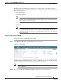
Enabling Web and Secure Web Modes 2
Using the GUI to Enable Web and Secure Web Modes 3
Using the CLI to Enable Web and Secure Web Modes 4
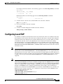
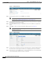
Loading an Externally Generated SSL Certificate 5
Using the CLI 7
Logging into the CLI 7
Using a Local Serial Connection 7
Using a Remote Ethernet Connection
Logging Out of the CLI 8
Navigating the CLI 9
8
Enabling Wireless Connections to the Web-Browser and
CLI Interfaces 9
Configuring Ports and Interfaces
1
Overview of Ports and Interfaces 2
Ports 2
Distribution System Ports 4
Service Port 5
Interfaces 5
Management Interface 6
Cisco Wireless LAN Controller Configuration Guide
4
OL-13826-01
Contents
AP-Manager Interface 6
Virtual Interface 7
Service-Port Interface 8
Dynamic Interface 8
WLANs 8
Configuring the Management, AP-Manager, Virtual, and Service-Port Interfaces 10
Using the GUI to Configure the Management, AP-Manager, Virtual, and Service-Port Interfaces 10
Using the CLI to Configure the Management, AP-Manager, Virtual, and Service-Port Interfaces 12
Using the CLI to Configure the Management Interface 12
Using the CLI to Configure the AP-Manager Interface 13
Using the CLI to Configure the Virtual Interface 14
Using the CLI to Configure the Service-Port Interface 14
Configuring Dynamic Interfaces 15
Using the GUI to Configure Dynamic Interfaces 15
Using the CLI to Configure Dynamic Interfaces 17
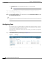
Configuring Ports 18
Configuring Port Mirroring 22
Configuring Spanning Tree Protocol 23
Using the GUI to Configure Spanning Tree Protocol 23
Using the CLI to Configure Spanning Tree Protocol 28
Enabling Link Aggregation 29
Link Aggregation Guidelines 31
Using the GUI to Enable Link Aggregation 32
Using the CLI to Enable Link Aggregation 33
Using the CLI to Verify Link Aggregation Settings 34
Configuring Neighbor Devices to Support LAG 34
Configuring a 4400 Series Controller to Support More Than 48 Access Points
Using Link Aggregation 35
Using Multiple AP-Manager Interfaces 35
Connecting Additional Ports 40
Configuring Controller SettingsWireless Device Access
35
1
Using the Configuration Wizard 2
Before You Start 2
Resetting the Device to Default Settings 3
Resetting to Default Settings Using the CLI 3
Resetting to Default Settings Using the GUI 3
Running the Configuration Wizard on the CLI 4
Cisco Wireless LAN Controller Configuration Guide
OL-13826-01
5
Contents
Managing the System Time and Date 6
Configuring an NTP Server to Obtain the Time and Date
Configuring the Time and Date Manually 7
6
Configuring 802.11 Bands 8
Using the GUI to Configure 802.11 Bands 8
Using the CLI to Configure 802.11 Bands 9
Configuring 802.11n Parameters 11
Using the GUI to Configure 802.11n Parameters 11
Using the CLI to Configure 802.11n Parameters 14
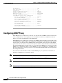
Configuring DHCP Proxy 18
Using the CLI to Configure DHCP Proxy
19
Configuring Administrator Usernames and Passwords
Configuring RADIUS Settings
Configuring SNMP
19
19
20
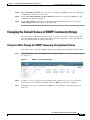
Changing the Default Values of SNMP Community Strings 21
Using the GUI to Change the SNMP Community String Default Values 21
Using the CLI to Change the SNMP Community String Default Values 22
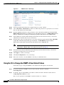
Changing the Default Values for SNMP v3 Users 23
Using the GUI to Change the SNMP v3 User Default Values 23
Using the CLI to Change the SNMP v3 User Default Values 24
Configuring Aggressive Load Balancing 25
Using the GUI to Configure Aggressive Load Balancing 25
Using the CLI to Configure Aggressive Load Balancing 26
Enabling 802.3x Flow Control
26
Enabling System Logging 26
Using the GUI to Enable System Logging 26
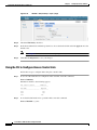
Using the GUI to View Message Logs 28
Using the CLI to Enable System Logging 28
Using the CLI to View Message Logs 29
Configuring 802.3 Bridging 29
Using the GUI to Configure 802.3 Bridging 29
Using the CLI to Configure 802.3 Bridging 30
Configuring Multicast Mode 31
Understanding Multicast Mode 31
Guidelines for Using Multicast Mode
32
Cisco Wireless LAN Controller Configuration Guide
6
OL-13826-01
Contents
Using the GUI to Enable Multicast Mode 33
Using the GUI to View Multicast Groups 34
Using the CLI to Enable Multicast Mode 34
Using the CLI to View Multicast Groups 35
Using the CLI to View an Access Point’s Multicast Client Table
36
Configuring Client Roaming 36
Intra-Controller Roaming 37
Inter-Controller Roaming 37
Inter-Subnet Roaming 37
Voice-over-IP Telephone Roaming 37
CCX Layer 2 Client Roaming 38
Using the GUI to Configure CCX Client Roaming Parameters 39
Using the CLI to Configure CCX Client Roaming Parameters 40
Using the CLI to Obtain CCX Client Roaming Information 40
Using the CLI to Debug CCX Client Roaming Issues 41
Configuring Quality of Service 41
Configuring Quality of Service Profiles 42
Using the GUI to Configure QoS Profiles 42
Using the CLI to Configure QoS Profiles 43
Configuring Quality of Service Roles 44
Using the GUI to Configure QoS Roles 45
Using the CLI to Configure QoS Roles 47
Configuring Voice and Video Parameters 48
Call Admission Control 48
Bandwidth-Based CAC 48
Load-Based CAC 49
Expedited Bandwidth Requests 49
U-APSD 50
Traffic Stream Metrics 50
Using the GUI to Configure Voice Parameters 51
Using the GUI to Configure Video Parameters 52
Using the GUI to View Voice and Video Settings 54
Using the CLI to Configure Voice Parameters 59
Using the CLI to Configure Video Parameters 61
Using the CLI to View Voice and Video Settings 62
Configuring EDCA Parameters 64
Using the GUI to Configure EDCA Parameters
Using the CLI to Configure EDCA Parameters
64
65
Cisco Wireless LAN Controller Configuration Guide
OL-13826-01
7
Contents
Configuring Cisco Discovery Protocol 66
Using the GUI to Configure Cisco Discovery Protocol 68
Using the GUI to View Cisco Discovery Protocol Information 69
Using the CLI to Configure Cisco Discovery Protocol 73
Using the CLI to View Cisco Discovery Protocol Information 74
Configuring RFID Tag Tracking 75
Using the CLI to Configure RFID Tag Tracking 77
Using the CLI to View RFID Tag Tracking Information 78
Using the CLI to Debug RFID Tag Tracking Issues 79
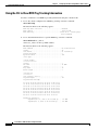
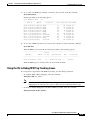
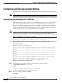
Configuring and Viewing Location Settings 80
Installing the Location Appliance Certificate 80
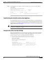
Synchronizing the Controller and Location Appliance
Using the CLI to View Location Settings 81
Configuring the Supervisor 720 to Support the WiSM
General WiSM Guidelines 83
Configuring the Supervisor 84
Using the Wireless LAN Controller Network Module
Configuring Security Solutions
81
83
85
1
Cisco UWN Solution Security 2
Security Overview 2
Layer 1 Solutions 2
Layer 2 Solutions 2
Layer 3 Solutions 3
Rogue Access Point Solutions 3
Rogue Access Point Challenges 3
Tagging and Containing Rogue Access Points
Integrated Security Solutions 4
Configuring TACACS+ 4
Configuring TACACS+ on the ACS 5
Using the GUI to Configure TACACS+ 9
Using the CLI to Configure TACACS+ 11
Viewing the TACACS+ Administration Server Logs
3
13
Configuring Local Network Users 15
Using the GUI to Configure Local Network Users 16
Using the CLI to Configure Local Network Users 18
Configuring LDAP
19
Cisco Wireless LAN Controller Configuration Guide
8
OL-13826-01
Contents
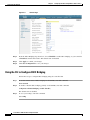
Using the GUI to Configure LDAP 19
Using the CLI to Configure LDAP 22
Configuring Local EAP 23
Using the GUI to Configure Local EAP 24
Using the CLI to Configure Local EAP 29
Configuring the System for SpectraLink NetLink Telephones 33
Using the GUI to Enable Long Preambles 33
Using the CLI to Enable Long Preambles 34
Using the CLI to Configure Enhanced Distributed Channel Access
35
Using Management over Wireless 35
Using the GUI to Enable Management over Wireless 35
Using the CLI to Enable Management over Wireless 36
Configuring DHCP Option 82
Validating SSIDs
36
37
Configuring and Applying Access Control Lists 38
Using the GUI to Configure Access Control Lists 38
Using the GUI to Apply Access Control Lists 42
Applying an Access Control List to an Interface 42
Applying an Access Control List to the Controller CPU 43
Applying an Access Control List to a WLAN 44
Applying a Preauthentication Access Control List to a WLAN
Using the CLI to Configure Access Control Lists 46
Using the CLI to Apply Access Control Lists 48
45
Configuring Management Frame Protection 49
Guidelines for Using MFP 50
Using the GUI to Configure MFP 51
Using the GUI to View MFP Settings 52
Using the CLI to Configure MFP 53
Using the CLI to View MFP Settings 54
Using the CLI to Debug MFP Issues 57
Configuring Client Exclusion Policies
57
Configuring Identity Networking 57
Identity Networking Overview 58
RADIUS Attributes Used in Identity Networking
QoS-Level 58
ACL-Name 59
58
Cisco Wireless LAN Controller Configuration Guide
OL-13826-01
9
Contents
Interface-Name 59
VLAN-Tag 60
Tunnel Attributes 60
Configuring AAA Override 61
Updating the RADIUS Server Dictionary File for Proper QoS Values
Using the GUI to Configure AAA Override 63
Using the CLI to Configure AAA Override 63
62
Configuring IDS 64
Configuring IDS Sensors 64
Using the GUI to Configure IDS Sensors 64
Using the CLI to Configure IDS Sensors 66
Viewing Shunned Clients 67
Configuring IDS Signatures 68
Using the GUI to Configure IDS Signatures 68
Using the CLI to Configure IDS Signatures 74
Using the CLI to View IDS Signature Events 75
Configuring AES Key Wrap 76
Using the GUI to Configure AES Key Wrap 76
Using the CLI to Configure AES Key Wrap 78
Configuring Maximum Local Database Entries 78
Using the GUI to Configure Maximum Local Database Entries 78
Using the CLI to Specify the Maximum Number of Local Database Entries
Configuring WLANsWireless Device Access
WLAN Overview
79
1
2
Configuring WLANs 2
Creating WLANs 2
Using the GUI to Create WLANs 3
Using the CLI to Create WLANs 5
Configuring DHCP 6
Internal DHCP Server 6
External DHCP Servers 6
DHCP Assignment 6
Security Considerations 7
Using the GUI to Configure DHCP 7
Using the CLI to Configure DHCP 8
Cisco Wireless LAN Controller Configuration Guide
10
OL-13826-01
Contents
Configuring DHCP Scopes 9
Configuring MAC Filtering for WLANs 12
Enabling MAC Filtering 12
Creating a Local MAC Filter 12
Configuring a Timeout for Disabled Clients 13
Assigning WLANs to Interfaces 13
Configuring Peer-to-Peer Blocking 13
Guidelines for Using Peer-to-Peer Blocking 14
Using the GUI to Configure Peer-to-Peer Blocking 14
Using the CLI to Configure Peer-to-Peer Blocking 15
Configuring Layer 2 Security 16
Static WEP Keys 16
Dynamic 802.1X Keys and Authorization 17
Configuring a WLAN for Both Static and Dynamic WEP 18
WPA1 and WPA2 18
CKIP 21
Configuring a Session Timeout 23
Using the GUI to Configure a Session Timeout 23
Using the CLI to Configure a Session Timeout 24
Configuring Layer 3 Security 24
VPN Passthrough 25
Web Authentication 25
Assigning a QoS Profile to a WLAN 26
Using the GUI to Assign a QoS Profile to a WLAN 27
Using the CLI to Assign a QoS Profile to a WLAN 28
Configuring QoS Enhanced BSS 29
Guidelines for Configuring QBSS 29
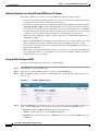
Additional Guidelines for Using 7921 and 7920 Wireless IP Phones
Using the GUI to Configure QBSS 30
Using the CLI to Configure QBSS 31
Configuring IPv6 Bridging 32
Guidelines for Using IPv6 Bridging 32
Using the GUI to Configure IPv6 Bridging 34
Using the CLI to Configure IPv6 Bridging 34
Configuring Cisco Client Extensions 35
Using the GUI to Configure CCX Aironet IEs 35
Using the GUI to View a Client’s CCX Version 35
Using the CLI to Configure CCX Aironet IEs 37
30
Cisco Wireless LAN Controller Configuration Guide
OL-13826-01
11
Contents
Using the CLI to View a Client’s CCX Version 37
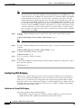
Configuring WLAN Override 37
Using the GUI to Configure WLAN Override 37
Using the CLI to Configure WLAN Override 38
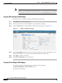
Configuring Access Point Groups 38
Creating Access Point Groups 40
Assigning Access Points to Access Point Groups 42
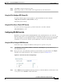
Configuring Conditional Web Redirect with 802.1X Authentication
Configuring the RADIUS Server 43
Using the GUI to Configure Conditional Web Redirect 44
Using the CLI to Configure Conditional Web Redirect 45
Disabling Accounting Servers per WLAN 46
Controlling Lightweight Access Points
43
1
The Controller Discovery Process 2
Verifying that Access Points Join the Controller 3
Using the GUI to Verify that Access Points Join the Controller 3
Using the CLI to Verify that Access Points Join the Controller 3
Cisco 1000 Series Lightweight Access Points 4
Cisco 1030 Remote Edge Lightweight Access Points 5
Cisco 1000 Series Lightweight Access Point Models 6
Cisco 1000 Series Lightweight Access Point External and Internal Antennas
External Antenna Connectors 6
Antenna Sectorization 7
Cisco 1000 Series Lightweight Access Point LEDs 7
Cisco 1000 Series Lightweight Access Point Connectors 8
Cisco 1000 Series Lightweight Access Point Power Requirements 8
Cisco 1000 Series Lightweight Access Point External Power Supply 9
Cisco 1000 Series Lightweight Access Point Mounting Options 9
Cisco 1000 Series Lightweight Access Point Physical Security 9
Cisco 1000 Series Lightweight Access Point Monitor Mode 9
Cisco Aironet 1510 Series Lightweight Outdoor Mesh Access Points 9
Wireless Mesh 10
Configuring and Deploying the AP1510 12
Adding the MAC Address of the Access Point to the Controller Filter List
Configuring Mesh Parameters 14
Configuring Bridging Parameters 17
Configuring Voice and Video Parameters in Mesh Networks 20
6
12
Cisco Wireless LAN Controller Configuration Guide
12
OL-13826-01
Contents
Using the CLI to View Voice and Video Details for Mesh Networks 21
Viewing Mesh Statistics for an Access Point 23
Using the GUI to View Mesh Statistics for an Access Point 24
Using the CLI to View Mesh Statistics for an Access Point 28
Viewing Neighbor Statistics for an Access Point 29
Using the GUI to View Neighbor Statistics for an Access Point 29
Using the CLI to View Neighbor Statistics for an Access Point 32
Background Scanning in Mesh Networks 33
Background Scanning Scenarios 34
Using the GUI to Enable Background Scanning 35
Using the CLI to Enable Background Scanning 36
Using the CLI to View Neighboring Access Points and Channels 36
Routing Around Interference 36
Using the CLI to Configure a Secondary Backhaul 37
Autonomous Access Points Converted to Lightweight Mode 37
Guidelines for Using Access Points Converted to Lightweight Mode 37
Reverting from Lightweight Mode to Autonomous Mode 38
Using a Controller to Return to a Previous Release 38
Using the MODE Button and a TFTP Server to Return to a Previous Release 39
Authorizing Access Points 39
Authorizing Access Points Using SSCs 39
Authorizing Access Points Using MICs 40
Using the GUI to Authorize Access Points 40
Using the CLI to Authorize Access Points 41
Using DHCP Option 43 41
Troubleshooting the Access Point Join Process 42
Configuring the Syslog Server for Access Points 44
Viewing Access Point Join Information 44
Using a Controller to Send Debug Commands to Access Points Converted to Lightweight Mode
Converted Access Points Send Crash Information to Controller 46
Converted Access Points Send Radio Core Dumps to Controller 46
Enabling Memory Core Dumps from Converted Access Points 47
Display of MAC Addresses for Converted Access Points 47
Disabling the Reset Button on Access Points Converted to Lightweight Mode 48
Configuring a Static IP Address on an Access Point Converted to Lightweight Mode 48
Supporting Oversized Access Point Images 48
Cisco Workgroup Bridges 49
Guidelines for Using WGBs
50
Cisco Wireless LAN Controller Configuration Guide
OL-13826-01
13
46
Contents
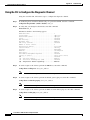
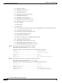
Sample WGB Configuration 52
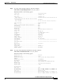
Using the GUI to View the Status of Workgroup Bridges 53
Using the CLI to View the Status of Workgroup Bridges 55
Using the CLI to Debug WGB Issues 56
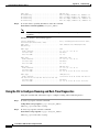
Configuring Backup Controllers 56
Using the CLI to Configure Backup Controllers
56
Configuring Country Codes 57
Guidelines for Configuring Multiple Country Codes
Using the GUI to Configure Country Codes 58
Using the CLI to Configure Country Codes 60
58
Migrating Access Points from the -J Regulatory Domain to the -U Regulatory Domain
Guidelines for Migration 64
Migrating Access Points to the -U Regulatory Domain 65
Dynamic Frequency Selection
63
66
Retrieving the Unique Device Identifier on Controllers and Access Points 67
Using the GUI to Retrieve the Unique Device Identifier on Controllers and Access Points 67
Using the CLI to Retrieve the Unique Device Identifier on Controllers and Access Points 69
Performing a Link Test 69
Using the GUI to Perform a Link Test 70
Using the CLI to Perform a Link Test 71
Configuring Power over Ethernet 72
Using the GUI to Configure Power over Ethernet 72
Using the CLI to Configure Power over Ethernet 74
Configuring Flashing LEDs
74
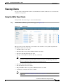
Viewing Clients 75
Using the GUI to View Clients 75
Using the CLI to View Clients 78
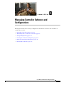
Managing Controller Software and Configurations
1
Upgrading Controller Software 2
Guidelines for Upgrading Controller Software 2
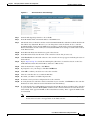
Using the GUI to Upgrade Controller Software 4
Using the CLI to Upgrade Controller Software 6
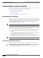
Transferring Files to and from a Controller 8
Downloading Device Certificates 8
Using the GUI to Download Device Certificates 8
Using the CLI to Download Device Certificates 9
Cisco Wireless LAN Controller Configuration Guide
14
OL-13826-01
Contents
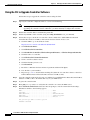
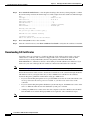
Downloading CA Certificates 10
Using the GUI to Download CA Certificates 11
Using the CLI to Download CA Certificates 11
Uploading PACs 12
Using the GUI to Upload PACs 13
Using the CLI to Upload PACs 13
Uploading and Downloading Configuration Files 14
Uploading Configuration Files 14
Downloading Configuration Files 16
Saving Configurations
18
Clearing the Controller Configuration
Erasing the Controller Configuration
Resetting the Controller
Managing User Accounts
18
18
19
1
Creating Guest User Accounts 2
Creating a Lobby Ambassador Account 2
Using the GUI to Create a Lobby Ambassador Account 2
Using the CLI to Create a Lobby Ambassador Account 3
Creating Guest User Accounts as a Lobby Ambassador 4
Viewing Guest User Accounts 6
Using the GUI to View Guest Accounts 6
Using the CLI to View Guest Accounts 7
Web Authentication Process
7
Choosing the Web Authentication Login Window 9
Choosing the Default Web Authentication Login Window 9
Using the GUI to Choose the Default Web Authentication Login Window 9
Using the CLI to Choose the Default Web Authentication Login Window 11
Modified Default Web Authentication Login Window Example 13
Creating a Customized Web Authentication Login Window 14
Using a Customized Web Authentication Login Window from an External Web Server 16
Using the GUI to Choose a Customized Web Authentication Login Window from an External Web
Server 16
Using the CLI to Choose a Customized Web Authentication Login Window from an External Web
Server 17
Downloading a Customized Web Authentication Login Window 17
Using the GUI to Download a Customized Web Authentication Login Window 18
Using the CLI to Download a Customized Web Authentication Login Window 19
Cisco Wireless LAN Controller Configuration Guide
OL-13826-01
15
Contents
Customized Web Authentication Login Window Example 20
Using the CLI to Verify the Web Authentication Login Window Settings
Assigning Login Pages per WLAN 21
Using the GUI to Assign Login Pages per WLAN 21
Using the CLI to Assign Login Pages per WLAN 22
20
Configuring Wired Guest Access 23
Configuration Overview 24
Configuration Guidelines 25
Using the GUI to Configure Wired Guest Access 25
Using the CLI to Configure Wired Guest Access 28
Configuring Radio Resource ManagementWireless Device Access
1
Overview of Radio Resource Management 2
Radio Resource Monitoring 2
Dynamic Channel Assignment 3
Dynamic Transmit Power Control 4
Coverage Hole Detection and Correction 4
RRM Benefits 5
Overview of RF Groups 5
RF Group Leader 6
RF Group Name 6
Configuring an RF Group 6
Using the GUI to Configure an RF Group 7
Using the CLI to Configure RF Groups 8
Viewing RF Group Status 8
Using the GUI to View RF Group Status 8
Using the CLI to View RF Group Status 10
Enabling Rogue Access Point Detection 11
Using the GUI to Enable Rogue Access Point Detection 11
Using the CLI to Enable Rogue Access Point Detection 14
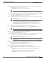
Configuring Dynamic RRM 14
Using the GUI to Configure Dynamic RRM 15
Using the CLI to Configure Dynamic RRM 22
Using the CLI to Debug RRM Issues 23
Overriding Dynamic RRM 24
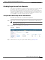
Statically Assigning Channel and Transmit Power Settings to Access Point Radios
Using the GUI to Statically Assign Channel and Transmit Power Settings 25
Using the CLI to Statically Assign Channel and Transmit Power Settings 27
25
Cisco Wireless LAN Controller Configuration Guide
16
OL-13826-01
Contents
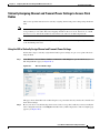
Disabling Dynamic Channel and Power Assignment Globally for a Controller 28
Using the GUI to Disable Dynamic Channel and Power Assignment 28
Using the CLI to Disable Dynamic Channel and Power Assignment 28
Viewing Additional RRM Settings Using the CLI
29
Configuring CCX Radio Management Features 29
Radio Measurement Requests 30
Location Calibration 30
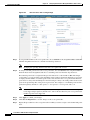
Using the GUI to Configure CCX Radio Management 30
Using the CLI to Configure CCX Radio Management 32
Using the CLI to Obtain CCX Radio Management Information
Using the CLI to Debug CCX Radio Management Issues 34
32
Configuring Pico Cell Mode 34
Guidelines for Using Pico Cell Mode 35
Using the GUI to Configure Pico Cell Mode 35
Using the CLI to Configure Pico Cell Mode 38
Using the CLI to Debug Pico Cell Mode Issues 38
Configuring Mobility GroupsWireless Device Access
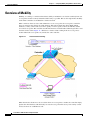
Overview of Mobility
1
2
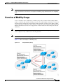
Overview of Mobility Groups 5
Determining When to Include Controllers in a Mobility Group
Using Mobility Groups with NAT Devices 7
7
Configuring Mobility Groups 8
Prerequisites 9
Using the GUI to Configure Mobility Groups 10
Using the CLI to Configure Mobility Groups 13
Viewing Mobility Group Statistics 13
Using the GUI to View Mobility Group Statistics 13
Using the CLI to View Mobility Group Statistics 16
Configuring Auto-Anchor Mobility 17
Guidelines for Using Auto-Anchor Mobility 18
Using the GUI to Configure Auto-Anchor Mobility 18
Using the CLI to Configure Auto-Anchor Mobility 20
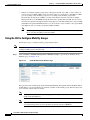
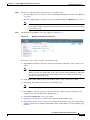
Configuring Symmetric Mobility Tunneling 22
Using the GUI to Configure Symmetric Mobility Tunneling 24
Using the CLI to Configure Symmetric Mobility Tunneling 25
Running Mobility Ping Tests
26
Cisco Wireless LAN Controller Configuration Guide
OL-13826-01
17
Contents
Configuring Hybrid REAPWireless Device Access
Overview of Hybrid REAP 2
Hybrid-REAP Authentication Process
Hybrid REAP Guidelines 4
1
2
Configuring Hybrid REAP 5
Configuring the Switch at the Remote Site 5
Configuring the Controller for Hybrid REAP 6
Using the GUI to Configure the Controller for Hybrid REAP 6
Using the CLI to Configure the Controller for Hybrid REAP 11
Configuring an Access Point for Hybrid REAP 11
Using the GUI to Configure an Access Point for Hybrid REAP 11
Using the CLI to Configure an Access Point for Hybrid REAP 14
Connecting Client Devices to the WLANs 15
Configuring Hybrid-REAP Groups 16
Using the GUI to Configure Hybrid-REAP Groups 17
Using the CLI to Configure Hybrid-REAP Groups 19
Safety Considerations and
Translated Safety Warnings
Safety Considerations
Warning Definition
1
2
2
Class 1 Laser Product Warning
Ground Conductor Warning
5
7
Chassis Warning for Rack-Mounting and Servicing
9
Battery Handling Warning for 4400 Series Controllers
Equipment Installation Warning
18
20
More Than One Power Supply Warning for 4400 Series Controllers
Declarations of Conformity and Regulatory Information
23
1
Regulatory Information for 1000 Series Access Points 2
Manufacturers Federal Communication Commission Declaration of Conformity Statement
Department of Communications—Canada 3
Canadian Compliance Statement 3
European Community, Switzerland, Norway, Iceland, and Liechtenstein 4
Declaration of Conformity with Regard to the R&TTE Directive 1999/5/EC 4
Declaration of Conformity for RF Exposure 5
Guidelines for Operating Cisco Aironet Access Points in Japan 6
Administrative Rules for Cisco Aironet Access Points in Taiwan 7
2
Cisco Wireless LAN Controller Configuration Guide
18
OL-13826-01
Contents
Access Points with IEEE 802.11a Radios
All Access Points 7
Declaration of Conformity Statements 8
7
FCC Statement for Cisco 2000 and 2100 Series Wireless LAN Controllers
FCC Statement for Cisco 4400 Series Wireless LAN Controllers
End User License and Warranty
8
9
1
End User License Agreement
2
Limited Warranty 4
Disclaimer of Warranty
6
General Terms Applicable to the Limited Warranty Statement and End User License Agreement
Additional Open Source Terms
Troubleshooting
7
1
Interpreting LEDs 2
Interpreting Controller LEDs 2
Interpreting Lightweight Access Point LEDs
System Messages
2
2
Using the CLI to Troubleshoot Problems
5
Configuring the Syslog Facility and Log Level
7
Uploading Core Dumps from the Controller 9
Using the CLI to Upload Controller Core Dumps
Monitoring Memory Leaks
9
10
Troubleshooting CCXv5 Client Devices 11
Diagnostic Channel 12
Client Reporting 12
Roaming and Real-Time Diagnostics 12
Using the GUI to Configure the Diagnostic Channel 13
Using the CLI to Configure the Diagnostic Channel 14
Using the GUI to Configure Client Reporting 18
Using the CLI to Configure Client Reporting 21
Using the CLI to Configure Roaming and Real-Time Diagnostics
Using the Debug Facility
24
27
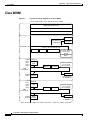
Logical Connectivity Diagrams
Cisco WiSM
6
1
2
Cisco Wireless LAN Controller Configuration Guide
OL-13826-01
19
Contents
Cisco 28/37/38xx Integrated Services Router
3
Catalyst 3750G Integrated Wireless LAN Controller Switch
4
INDEX
Cisco Wireless LAN Controller Configuration Guide
20
OL-13826-01
Preface
This preface provides an overview of the Cisco Wireless LAN Controller Configuration Guide, Release
4.2, references related publications, and explains how to obtain other documentation and technical
assistance, if necessary. It contains these sections:
•
Audience, page 22
•
Purpose, page 22
•
Organization, page 22
•
Conventions, page 23
•
Related Publications, page 25
•
Obtaining Documentation, Support, and Security Guidelines, page 26
Cisco Wireless LAN Controller Configuration Guide
OL-13826-01
21
Preface
Audience
Audience
This guide describes Cisco Wireless LAN Controllers and Cisco Lightweight Access Points. This guide
is for the networking professional who installs and manages these devices. To use this guide, you should
be familiar with the concepts and terminology of wireless LANs.
Purpose
This guide provides the information you need to set up and configure wireless LAN controllers.
Note
This version of the Cisco Wireless LAN Controller Configuration Guide pertains specifically to
controller software release 4.2. If you are using an earlier version of software, you will notice differences
in features, functionality, and GUI pages.
Organization
This guide is organized into these chapters:
Chapter 1, “Overview,” provides an overview of the network roles and features of wireless LAN
controllers.
Chapter 2, “Using the Web-Browser and CLI Interfaces,” describes how to use the controller GUI and
CLI.
Chapter 3, “Configuring Ports and Interfaces,” describes the controller’s physical ports and interfaces
and provides instructions for configuring them.
Chapter 4, “Configuring Controller SettingsWireless Device Access,” describes how to configure
settings on the controllers.
Chapter 5, “Configuring Security Solutions,” describes application-specific solutions for wireless
LANs.
Chapter 6, “Configuring WLANsWireless Device Access,” describes how to configure wireless LANs
and SSIDs on your system.
Chapter 7, “Controlling Lightweight Access Points,” explains how to connect access points to the
controller and manage access point settings.
Chapter 8, “Managing Controller Software and Configurations,” describes how to upgrade and manage
controller software and configurations.
Chapter 9, “Managing User Accounts,” explains how to create and manage guest user accounts,
describes the web authentication process, and provides instructions for customizing the web
authentication login window.
Chapter 10, “Configuring Radio Resource ManagementWireless Device Access,” describes radio
resource management (RRM) and explains how to configure it on the controllers.
Chapter 11, “Configuring Mobility GroupsWireless Device Access,” describes mobility groups and
explains how to configure them on the controllers.
Chapter 12, “Configuring Hybrid REAPWireless Device Access,” describes hybrid REAP and explains
how to configure this feature on controllers and access points.
Cisco Wireless LAN Controller Configuration Guide
22
OL-13826-01
Preface
Conventions
Appendix A, “Safety Considerations and Translated Safety Warnings,” lists safety considerations and
translations of the safety warnings that apply to the Cisco Unified Wireless Network Solution products.
Appendix B, “Declarations of Conformity and Regulatory Information,” provides declarations of
conformity and regulatory information for the products in the Cisco Unified Wireless Network Solution.
Appendix C, “End User License and Warranty,” describes the end user license and warranty that apply
to the Cisco Unified Wireless Network Solution products.
Appendix D, “Troubleshooting,” describes the LED patterns on controllers and lightweight access
points, lists system messages that can appear on the Cisco Unified Wireless Network Solution interfaces,
and provides CLI commands that can be used to troubleshoot problems on the controller.
Appendix E, “Logical Connectivity Diagrams,”provides logical connectivity diagrams and related
software commands for controllers that are integrated into other Cisco products.
Conventions
This publication uses these conventions to convey instructions and information:
Command descriptions use these conventions:
•
Commands and keywords are in boldface text.
•
Arguments for which you supply values are in italic.
•
Square brackets ([ ]) mean optional elements.
•
Braces ({ }) group required choices, and vertical bars ( | ) separate the alternative elements.
•
Braces and vertical bars within square brackets ([{ | }]) mean a required choice within an optional
element.
Interactive examples use these conventions:
•
Terminal sessions and system displays are in screen font.
•
Information you enter is in boldface.
•
Nonprinting characters, such as passwords or tabs, are in angle brackets (< >).
Notes, cautions, and timesavers use these conventions and symbols:
Note
Caution
Means reader take note. Notes contain helpful suggestions or references to materials not contained in
this manual.
Means reader be careful. In this situation, you might do something that could result equipment damage
or loss of data.
Cisco Wireless LAN Controller Configuration Guide
OL-13826-01
23
Preface
Conventions
Warning
Waarschuwing
This warning symbol means danger. You are in a situation that could cause bodily injury. Before you
work on any equipment, be aware of the hazards involved with electrical circuitry and be familiar
with standard practices for preventing accidents. (To see translations of the warnings that appear
in this publication, refer to the appendix “Translated Safety Warnings.”)
Dit waarschuwingssymbool betekent gevaar. U verkeert in een situatie die lichamelijk letsel kan
veroorzaken. Voordat u aan enige apparatuur gaat werken, dient u zich bewust te zijn van de bij
elektrische schakelingen betrokken risico’s en dient u op de hoogte te zijn van standaard
maatregelen om ongelukken te voorkomen. (Voor vertalingen van de waarschuwingen die in deze
publicatie verschijnen, kunt u het aanhangsel “Translated Safety Warnings” (Vertalingen van
veiligheidsvoorschriften) raadplegen.)
Varoitus
Tämä varoitusmerkki merkitsee vaaraa. Olet tilanteessa, joka voi johtaa ruumiinvammaan. Ennen
kuin työskentelet minkään laitteiston parissa, ota selvää sähkökytkentöihin liittyvistä vaaroista ja
tavanomaisista onnettomuuksien ehkäisykeinoista. (Tässä julkaisussa esiintyvien varoitusten
käännökset löydät liitteestä "Translated Safety Warnings" (käännetyt turvallisuutta koskevat
varoitukset).)
Attention
Ce symbole d’avertissement indique un danger. Vous vous trouvez dans une situation pouvant
entraîner des blessures. Avant d’accéder à cet équipement, soyez conscient des dangers posés par
les circuits électriques et familiarisez-vous avec les procédures courantes de prévention des
accidents. Pour obtenir les traductions des mises en garde figurant dans cette publication, veuillez
consulter l’annexe intitulée « Translated Safety Warnings » (Traduction des avis de sécurité).
Warnung
Dieses Warnsymbol bedeutet Gefahr. Sie befinden sich in einer Situation, die zu einer
Körperverletzung führen könnte. Bevor Sie mit der Arbeit an irgendeinem Gerät beginnen, seien Sie
sich der mit elektrischen Stromkreisen verbundenen Gefahren und der Standardpraktiken zur
Vermeidung von Unfällen bewußt. (Übersetzungen der in dieser Veröffentlichung enthaltenen
Warnhinweise finden Sie im Anhang mit dem Titel “Translated Safety Warnings” (Übersetzung der
Warnhinweise).)
Avvertenza
Questo simbolo di avvertenza indica un pericolo. Si è in una situazione che può causare infortuni.
Prima di lavorare su qualsiasi apparecchiatura, occorre conoscere i pericoli relativi ai circuiti
elettrici ed essere al corrente delle pratiche standard per la prevenzione di incidenti. La traduzione
delle avvertenze riportate in questa pubblicazione si trova nell’appendice, “Translated Safety
Warnings” (Traduzione delle avvertenze di sicurezza).
Advarsel
Dette varselsymbolet betyr fare. Du befinner deg i en situasjon som kan føre til personskade. Før du
utfører arbeid på utstyr, må du være oppmerksom på de faremomentene som elektriske kretser
innebærer, samt gjøre deg kjent med vanlig praksis når det gjelder å unngå ulykker. (Hvis du vil se
oversettelser av de advarslene som finnes i denne publikasjonen, kan du se i vedlegget "Translated
Safety Warnings" [Oversatte sikkerhetsadvarsler].)
Aviso
Este símbolo de aviso indica perigo. Encontra-se numa situação que lhe poderá causar danos
fisicos. Antes de começar a trabalhar com qualquer equipamento, familiarize-se com os perigos
relacionados com circuitos eléctricos, e com quaisquer práticas comuns que possam prevenir
possíveis acidentes. (Para ver as traduções dos avisos que constam desta publicação, consulte o
apêndice “Translated Safety Warnings” - “Traduções dos Avisos de Segurança”).
Cisco Wireless LAN Controller Configuration Guide
24
OL-13826-01
Preface
Related Publications
¡Advertencia!
Este símbolo de aviso significa peligro. Existe riesgo para su integridad física. Antes de manipular
cualquier equipo, considerar los riesgos que entraña la corriente eléctrica y familiarizarse con los
procedimientos estándar de prevención de accidentes. (Para ver traducciones de las advertencias
que aparecen en esta publicación, consultar el apéndice titulado “Translated Safety Warnings.”)
Varning!
Denna varningssymbol signalerar fara. Du befinner dig i en situation som kan leda till personskada.
Innan du utför arbete på någon utrustning måste du vara medveten om farorna med elkretsar och
känna till vanligt förfarande för att förebygga skador. (Se förklaringar av de varningar som
förekommer i denna publikation i appendix "Translated Safety Warnings" [Översatta
säkerhetsvarningar].)
Related Publications
These documents provide complete information about the Cisco Unified Wireless Network Solution:
•
Quick Start Guide: Cisco 2000 Series Wireless LAN Controllers
•
Quick Start Guide: Cisco 2100 Series Wireless LAN Controllers
•
Quick Start Guide: Cisco 4400 Series Wireless LAN Controllers
•
Cisco Wireless LAN Controller Command Reference
•
Cisco Wireless Control System Configuration Guide
•
Quick Start Guide: Cisco Wireless Control System
•
Quick start guide and hardware installation guide for your specific lightweight access point
Click this link to browse to the Cisco Support and Documentation page:
http://www.cisco.com/cisco/web/support/index.html
•
Cisco 1800 Series Routers Hardware Installation Guide
•
Cisco AP HWIC Wireless Configuration Guide
•
Cisco Router and Security Device Manager (SDM) Quick Start Guide
•
Cisco Aironet 2.4-GHz Articulated Dipole Antenna (AIR-ANT4941)
•
Cisco Aironet High Gain Omnidirectional Ceiling Mount Antenna (AIR-ANT1728)
•
Mounting Instructions for the Cisco Aironet 6.5 dBi Diversity Patch Wall Mount Antenna
•
Cisco Aironet 2 dBi Diversity Omnidirectional Ceiling Mount Antenna (AIR-ANT5959)
•
Cisco Multiband 2.4/5GHz Articulated Dipole Antenna (AIR-ANT1841)
•
Cisco Multiband 2.4/5G Diversity Omnidirectional Ceiling Mount Antenna (AIR-ANT1828)
•
Cisco Multiband 2.4/5G Patch Wall Mount Antenna (AIR-ANT1859)
•
Mounting Instructions for the Cisco Diversity Omnidirectional Ceiling Mount Antenna
•
Mounting Instructions for the Cisco Patch Wall Mount Antenna
Related documents from the Cisco TAC Web pages include:
•
Antenna Cabling
Cisco Wireless LAN Controller Configuration Guide
OL-13826-01
25
Preface
Obtaining Documentation, Support, and Security Guidelines
Obtaining Documentation, Support, and Security Guidelines
For information on obtaining documentation, obtaining support, providing documentation feedback,
security guidelines, and also recommended aliases and general Cisco documents, see the monthly
What’s New in Cisco Product Documentation, which also lists all new and revised Cisco technical
documentation, at:
http://www.cisco.com/en/US/docs/general/whatsnew/whatsnew.html
Cisco Wireless LAN Controller Configuration Guide
26
OL-13826-01
CH A P T E R
1
Overview
This chapter describes the controller components and features. Its contains these sections:
•
Cisco Unified Wireless Network Solution Overview, page 1-2
•
Operating System Software, page 1-5
•
Operating System Security, page 1-5
•
Layer 2 and Layer 3 LWAPP Operation, page 1-6
•
Cisco Wireless LAN Controllers, page 1-7
•
Controller Platforms, page 1-8
•
Cisco UWN Solution Wired Connections, page 1-13
•
Cisco UWN Solution WLANs, page 1-14
•
Identity Networking, page 1-14
•
File Transfers, page 1-16
•
Power over Ethernet, page 1-16
•
Startup Wizard, page 1-17
•
Cisco Wireless LAN Controller Memory, page 1-18
•
Cisco Wireless LAN Controller Failover Protection, page 1-18
•
Network Connections to Cisco Wireless LAN Controllers, page 1-19
•
Rogue Access Points, page 1-21
Cisco Wireless LAN Controller Configuration Guide
OL-13826-01
1-1
Chapter 1
Overview
Cisco Unified Wireless Network Solution Overview
Cisco Unified Wireless Network Solution Overview
The Cisco Unified Wireless Network (Cisco UWN) Solution is designed to provide 802.11 wireless
networking solutions for enterprises and service providers. The Cisco UWN Solution simplifies
deploying and managing large-scale wireless LANs and enables a unique best-in-class security
infrastructure. The operating system manages all data client, communications, and system
administration functions, performs radio resource management (RRM) functions, manages system-wide
mobility policies using the operating system security solution, and coordinates all security functions
using the operating system security framework.
The Cisco UWN Solution consists of Cisco Wireless LAN Controllers and their associated lightweight
access points controlled by the operating system, all concurrently managed by any or all of the operating
system user interfaces:
•
An HTTP and/or HTTPS full-featured Web User Interface hosted by Cisco Wireless LAN
Controllers can be used to configure and monitor individual controllers. See Chapter 2.
•
A full-featured command-line interface (CLI) can be used to configure and monitor individual Cisco
Wireless LAN Controllers. See Chapter 2.
•
The Cisco Wireless Control System (WCS), which you use to configure and monitor one or more
Cisco Wireless LAN Controllers and associated access points. WCS has tools to facilitate
large-system monitoring and control. WCS runs on Windows 2000, Windows 2003, and Red Hat
Enterprise Linux ES servers.
Note
•
WCS software release 4.2 must be used with controllers running controller software release
4.2. Do not attempt to use older versions of WCS software with controllers running
controller software release 4.2.
An industry-standard SNMP V1, V2c, and V3 interface can be used with any SNMP-compliant
third-party network management system.
The Cisco UWN Solution supports client data services, client monitoring and control, and all rogue
access point detection, monitoring, and containment functions. It uses lightweight access points, Cisco
Wireless LAN Controllers, and the optional Cisco WCS to provide wireless services to enterprises and
service providers.
Note
Unless otherwise noted, all of the Cisco wireless LAN controllers are hereafter referred to as controllers,
and all of the Cisco lightweight access points are hereafter referred to as access points.
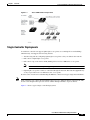
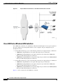
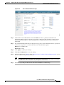
Figure 1-1 shows the Cisco Wireless LAN Solution components, which can be simultaneously deployed
across multiple floors and buildings.
Cisco Wireless LAN Controller Configuration Guide
1-2
OL-13826-01
Chapter 1
Overview
Cisco Unified Wireless Network Solution Overview
Figure 1-1
Cisco UWN Solution Components
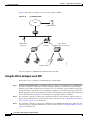
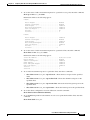
Single-Controller Deployments
A standalone controller can support lightweight access points across multiple floors and buildings
simultaneously, and supports the following features:
•
Autodetecting and autoconfiguring lightweight access points as they are added to the network.
•
Full control of lightweight access points.
•
Full control of up to 16 wireless LAN (SSID) policies for Cisco 1000 series access points.
Note
•
LWAPP-enabled access points support up to 8 wireless LAN (SSID) policies.
Lightweight access points connect to controllers through the network. The network equipment may
or may not provide Power over Ethernet to the access points.
Note that some controllers use redundant Gigabit Ethernet connections to bypass single network failures.
Note
Some controllers can connect through multiple physical ports to multiple subnets in the network. This
feature can be helpful when operators want to confine multiple VLANs to separate subnets.
Figure 1-2 shows a typical single-controller deployment.
Cisco Wireless LAN Controller Configuration Guide
OL-13826-01
1-3
Chapter 1
Overview
Cisco Unified Wireless Network Solution Overview
Figure 1-2
Single-Controller Deployment
Multiple-Controller Deployments
Each controller can support lightweight access points across multiple floors and buildings
simultaneously. However, full functionality of the Cisco Wireless LAN Solution is realized when it
includes multiple controllers. A multiple-controller system has the following additional features:
•
Autodetecting and autoconfiguring RF parameters as the controllers are added to the network.
•
Same-Subnet (Layer 2) Roaming and Inter-Subnet (Layer 3) Roaming.
•
Automatic access point failover to any redundant controller with a reduced access point load (refer
to the “Cisco Wireless LAN Controller Failover Protection” section on page 1-18).
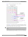
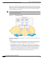
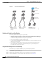
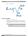
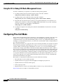
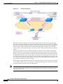
Figure 1-3 shows a typical multiple-controller deployment. The figure also shows an optional dedicated
Management Network and the three physical connection types between the network and the controllers.
Cisco Wireless LAN Controller Configuration Guide
1-4
OL-13826-01
Chapter 1
Overview
Operating System Software
Figure 1-3
Typical Multi-Controller Deployment
Operating System Software
The operating system software controls Cisco Wireless LAN Controllers and Cisco 1000 Series
Lightweight Access Points. It includes full operating system security and Radio Resource Management
(RRM) features.
Operating System Security
Operating system security bundles Layer 1, Layer 2, and Layer 3 security components into a simple,
Cisco WLAN Solution-wide policy manager that creates independent security policies for each of up to
16 wireless LANs. (Refer to the “Cisco UWN Solution WLANs” section on page 1-14.)
The 802.11 Static WEP weaknesses can be overcome using robust industry-standard security solutions,
such as:
•
802.1X dynamic keys with extensible authentication protocol (EAP).
•
Wi-Fi protected access (WPA) dynamic keys. The Cisco WLAN Solution WPA implementation
includes:
– Temporal key integrity protocol (TKIP) + message integrity code checksum (Michael) dynamic
keys, or
– WEP keys, with or without Pre-Shared key Passphrase.
Cisco Wireless LAN Controller Configuration Guide
OL-13826-01
1-5
Chapter 1
Overview
Layer 2 and Layer 3 LWAPP Operation
•
RSN with or without Pre-Shared key.
•
Cranite FIPS140-2 compliant passthrough.
•
Optional MAC filtering.
The WEP problem can be further solved using industry-standard Layer 3 security solutions, such as:
•
Passthrough VPNs
•
The Cisco Wireless LAN Solution supports local and RADIUS MAC address filtering.
•
The Cisco Wireless LAN Solution supports local and RADIUS user/password authentication.
•
The Cisco Wireless LAN Solution also uses manual and automated disabling to block access to
network services. In manual disabling, the operator blocks access using client MAC addresses. In
automated disabling, which is always active, the operating system software automatically blocks
access to network services for an operator-defined period of time when a client fails to authenticate
for a fixed number of consecutive attempts. This can be used to deter brute-force login attacks.
These and other security features use industry-standard authorization and authentication methods to
ensure the highest possible security for your business-critical wireless LAN traffic.
Cisco WLAN Solution Wired Security
Many traditional access point vendors concentrate on security for the Wireless interface similar to that
described in the “Operating System Security” section on page 1-5. However, for secure Cisco Wireless
LAN Controller Service Interfaces, Cisco Wireless LAN Controller to access point, and inter-Cisco
Wireless LAN Controller communications during device servicing and client roaming, the operating
system includes built-in security.
Each Cisco Wireless LAN Controller and Cisco 1000 series lightweight access point is manufactured
with a unique, signed X.509 certificate. These signed certificates are used to verify downloaded code
before it is loaded, ensuring that hackers do not download malicious code into any Cisco Wireless LAN
Controller or Cisco 1000 series lightweight access point.
Cisco Wireless LAN Controllers and Cisco 1000 series lightweight access points also use the signed
certificates to verify downloaded code before it is loaded, ensuring that hackers do not download
malicious code into any Cisco Wireless LAN Controller or Cisco 1000 series lightweight access point.
Layer 2 and Layer 3 LWAPP Operation
The LWAPP communications between Cisco Wireless LAN Controller and Cisco 1000 series
lightweight access points can be conducted at ISO Data Link Layer 2 or Network Layer 3.
Note
The IPv4 network layer protocol is supported for transport through an LWAPP controller system. IPv6
(for clients only) and Appletalk are also supported but only on 4400 series controllers and the Cisco
WiSM. Other Layer 3 protocols (such as IPX, DECnet Phase IV, OSI CLNP, and so on) and Layer 2
(bridged) protocols (such as LAT and NetBeui) are not supported.
Cisco Wireless LAN Controller Configuration Guide
1-6
OL-13826-01
Chapter 1
Overview
Cisco Wireless LAN Controllers
Operational Requirements
The requirement for Layer 2 LWAPP communications is that the Cisco Wireless LAN Controller and
Cisco 1000 series lightweight access points must be connected to each other through Layer 2 devices on
the same subnet. This is the default operational mode for the Cisco Wireless LAN Solution. Note that
when the Cisco Wireless LAN Controller and Cisco 1000 series lightweight access points are on
different subnets, these devices must be operated in Layer 3 mode.
The requirement for Layer 3 LWAPP communications is that the Cisco Wireless LAN Controllers and
Cisco 1000 series lightweight access points can be connected through Layer 2 devices on the same
subnet or connected through Layer 3 devices across subnets. Another requirement is that the IP
addresses of access points should be either statically assigned or dynamically assigned through an
external DHCP server.
Note that all Cisco Wireless LAN Controllers in a mobility group must use the same LWAPP Layer 2 or
Layer 3 mode, or you will defeat the Mobility software algorithm.
Configuration Requirements
When you are operating the Cisco Wireless LAN Solution in Layer 2 mode, you must configure a
management interface to control your Layer 2 communications.
When you are operating the Cisco Wireless LAN Solution in Layer 3 mode, you must configure an
AP-manager interface to control Cisco 1000 series lightweight access points and a management interface
as configured for Layer 2 mode.
Cisco Wireless LAN Controllers
When you are adding Cisco 1000 series lightweight access points to a multiple Cisco Wireless LAN
Controller deployments network, it is convenient to have all Cisco 1000 series lightweight access points
associate with one master controller on the same subnet. That way, the operator does not have to log into
multiple controllers to find out which controller newly-added Cisco 1000 series lightweight access
points associated with.
One controller in each subnet can be assigned as the master controller while adding lightweight access
points. As long as a master controller is active on the same subnet, all new access points without a
primary, secondary, and tertiary controller assigned automatically attempt to associate with the master
Cisco Wireless LAN Controller. This process is described in the “Cisco Wireless LAN Controller
Failover Protection” section on page 1-18.
The operator can monitor the master controller using the WCS Web User Interface and watch as access
points associate with the master controller. The operator can then verify access point configuration and
assign a primary, secondary, and tertiary controller to the access point, and reboot the access point so it
reassociates with its primary, secondary, or tertiary controller.
Note
Lightweight access points without a primary, secondary, and tertiary controller assigned always search
for a master controller first upon reboot. After adding lightweight access points through the master
controller, assign primary, secondary, and tertiary controllers to each access point. Cisco recommends
that you disable the master setting on all controllers after initial configuration.
Cisco Wireless LAN Controller Configuration Guide
OL-13826-01
1-7
Chapter 1
Overview
Controller Platforms
Primary, Secondary, and Tertiary Controllers
In multiple-controller networks, lightweight access points can associate with any controller on the same
subnet. To ensure that each access point associates with a particular controller, the operator can assign
primary, secondary, and tertiary controllers to the access point.
When a primed access point is added to a network, it looks for its primary, secondary, and tertiary
controllers first, then a master controller, then the least-loaded controller with available access point
ports. Refer to the “Cisco Wireless LAN Controller Failover Protection” section on page 1-18 for more
information.
Client Location
When you use Cisco WCS in your Cisco Wireless LAN Solution, controllers periodically determine
client, rogue access point, rogue access point client, radio frequency ID (RFID) tag location and store
the locations in the Cisco WCS database. For more information on location solutions, refer to the Cisco
Wireless Control System Configuration Guide and the Cisco Location Appliance Configuration Guide at
these URLs:
Cisco Wireless Control System Configuration Guide:
http://www.cisco.com/en/US/products/ps6305/products_installation_and_configuration_guides_list.ht
ml
Cisco Location Appliance Configuration Guide:
http://www.cisco.com/en/US/products/ps6386/products_installation_and_configuration_guides_list.ht
ml
Controller Platforms
Controllers are enterprise-class high-performance wireless switching platforms that support 802.11a/n
and 802.11b/g/n protocols. They operate under control of the operating system, which includes the radio
resource management (RRM), creating a Cisco UWN Solution that can automatically adjust to real-time
changes in the 802.11 RF environment. The controllers are built around high-performance network and
security hardware, resulting in highly-reliable 802.11 enterprise networks with unparalleled security.
The following controllers are supported for use with software release 4.2:
•
Cisco 2000 series controllers
•
Cisco 2100 series controllers
•
Cisco 4400 series controllers
•
Catalyst 6500 Series Wireless Services Module (WiSM)
•
Cisco 7600 Series Router Wireless Services Module (WiSM)
•
Cisco 28/37/38xx Series Integrated Services Router with Controller Network Module
•
Catalyst 3750G Integrated Wireless LAN Controller Switch
The first three controllers are stand-alone platforms. The remaining four controllers are integrated into
Cisco switch and router products.
Cisco Wireless LAN Controller Configuration Guide
1-8
OL-13826-01
Chapter 1
Overview
Controller Platforms
Cisco 2000 and 2100 Series Controllers
The Cisco 2000 and 2100 Series Wireless LAN Controllers work in conjunction with Cisco lightweight
access points and the Cisco Wireless Control System (WCS) to provide system-wide wireless LAN
functions. Each 2000 and 2100 series controller controls up to six lightweight access points for
multi-controller architectures typical of enterprise branch deployments. It may also be used for single
controller deployments for small and medium-sized environments.
Caution
Do not connect a power-over-Ethernet (PoE) cable to the controller’s console port. Doing so may damage
the controller.
Note
Wait at least 20 seconds before reconnecting an access point to the controller. Otherwise, the controller
may fail to detect the device.
Features Not Supported
These hardware features are not supported on 2000 and 2100 series controllers:
•
Power over Ethernet (PoE) [2000 series controllers only]
Note
•
Ports 7 and 8 on 2100 series controllers are PoE ports.
Service port (separate out-of-band management 10/100-Mbps Ethernet interface)
These software features are not supported on 2000 and 2100 series controllers:
•
VPN termination (such as IPSec and L2TP)
•
Termination of guest controller tunnels (origination of guest controller tunnels is supported)
•
External web authentication web server list
•
Layer 2 LWAPP
•
Spanning tree
•
Port mirroring
•
Cranite
•
Fortress
•
AppleTalk
•
QoS per-user bandwidth contracts
•
IPv6 pass-through
•
Link aggregation (LAG)
Cisco Wireless LAN Controller Configuration Guide
OL-13826-01
1-9
Chapter 1
Overview
Controller Platforms
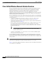
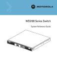
Cisco 4400 Series Controllers
The Cisco 4400 Series Wireless LAN Controller is available in two models: 4402 and 4404. The 4402
supports up to 50 lightweight access points while the 4404 supports up to 100, making it ideal for
large-sized enterprises and large-density applications.
Figure - Cisco 4400 Series Wireless LAN Controller
The Cisco 4400 Series Wireless LAN Controller can be factory-ordered with a VPN/Enhanced
Security Module (Crypto Card) to support VPN, IPSec and other processor-intensive tasks. The
VPN/Enhanced Security Module can also be installed in the field.
The 4400 series controller can be equipped with one or two Cisco 4400 series power supplies. When the
controller is equipped with two Cisco 4400 series power supplies, the power supplies are redundant, and
either power supply can continue to power the controller if the other power supply fails.
Catalyst 6500 Series Wireless Services Module
The Catalyst 6500 Series Wireless Services Module (WiSM) is an integrated Catalyst 6500 switch and
two Cisco 4404 controllers that supports up to 300 lightweight access points. The switch has eight
internal Gigabit Ethernet ports that connect the switch and the controller. The switch and the internal
controller run separate software versions, which must be upgraded separately.
Note
The Catalyst 6500 Series Switch chassis can support up to six Cisco WiSMs without any other service
module installed. If one or more service modules are installed, the chassis can support up to a maximum
of four service modules (WiSMs included).
Note
The Cisco WiSM controllers do not support port mirroring.
Refer to the following documents for additional information:
•
Catalyst 6500 Series Switch Installation Guide
•
Catalyst 6500 Series Switch Wireless Services Module Installation and Configuration Note
•
Release Notes for Catalyst 6500 Series Switch Wireless LAN Services Module
•
Configuring a Cisco Wireless Services Module and Wireless Control System
•
Catalyst 6500 Series Switch and Cisco 7600 Series Router Wireless Services Module Installation
and Verification Note
You can find these documents at these URLs:
http://www.cisco.com/en/US/products/hw/switches/ps708/tsd_products_support_series_home.html
http://www.cisco.com/en/US/docs/wireless/technology/wism/technical/reference/appnote.html
Cisco Wireless LAN Controller Configuration Guide
1-10
OL-13826-01
Chapter 1
Overview
Controller Platforms
http://www.cisco.com/en/US/docs/wireless/technology/wism/installation/note/78_17121.html
Cisco 7600 Series Router Wireless Services Module
The Cisco 7600 Series Router Wireless Services Module (WiSM) is an integrated Cisco 7600 router and
two Cisco 4404 controllers that supports up to 300 lightweight access points. The router has eight
internal Gigabit Ethernet ports that connect the router and the controller. The router and the internal
controller run separate software versions, which must be upgraded separately.
Note
The WiSM is supported on Cisco 7600 series routers running only Cisco IOS Release 12.2(18)SXF5 or
later.
Note
The Cisco 7600 series router chassis can support up to six Cisco WiSMs without any other service
module installed. If one or more service modules are installed, the chassis can support up to four service
modules (WiSMs included).
Note
The Cisco WiSM controllers do not support port mirroring.
Refer to the following documents for additional information:
•
Cisco 7600 Series Router Installation Guide
•
Cisco 7600 Series Router Software Configuration Guide
•
Cisco 7600 Series Router Command Reference
•
Configuring a Cisco Wireless Services Module and Wireless Control System
•
Catalyst 6500 Series Switch and Cisco 7600 Series Router Wireless Services Module Installation
and Verification Note
You can find these documents at these URLs:
http://www.cisco.com/en/US/products/hw/routers/ps368/tsd_products_support_series_home.html
http://www.cisco.com/en/US/docs/wireless/technology/wism/technical/reference/appnote.html
http://www.cisco.com/en/US/docs/wireless/technology/wism/installation/note/78_17121.html
Cisco 28/37/38xx Series Integrated Services Router
The Cisco 28/37/38xx Series Integrated Services Router is an integrated 28/37/38xx router and Cisco
controller network module that supports up to 6, 8, or 12 lightweight access points, depending on the
version of the network module. The versions that support 8 and 12 access points feature a high-speed
processor and more on-board memory. An internal Fast Ethernet port (on the 6-access point version) or
an internal Gigabit Ethernet port (on the 8- and 12-access point versions) connects the router and the
integrated controller. The router and the internal controller run separate software versions, which must
be upgraded separately. Refer to the following documents for additional information:
•
Cisco Wireless LAN Controller Network Module Feature Guide
•
Cisco 28/37/38xx Series Hardware Installation Guide
Cisco Wireless LAN Controller Configuration Guide
OL-13826-01
1-11
Chapter 1
Overview
Controller Platforms
You can find these documents at this URL:
http://www.cisco.com/en/US/products/hw/wireless/index.html
Note
The controller network module does not support port mirroring.
Note
The Cisco 2801 Integrated Services Router does not support the controller network module.
Cisco Wireless LAN Controller Configuration Guide
1-12
OL-13826-01
Chapter 1
Overview
Cisco UWN Solution Wired Connections
Catalyst 3750G Integrated Wireless LAN Controller Switch
The Catalyst 3750G Integrated Wireless LAN Controller Switch is an integrated Catalyst 3750 switch
and Cisco 4400 series controller that supports up to 25 or 50 lightweight access points. The switch has
two internal Gigabit Ethernet ports that connect the switch and the controller. The switch and the internal
controller run separate software versions, which must be upgraded separately. Refer to the following
documents for additional information:
•
Catalyst 3750G Integrated Wireless LAN Controller Switch Getting Started Guide
•
Catalyst 3750 Switch Hardware Installation Guide
•
Release Notes for the Catalyst 3750 Integrated Wireless LAN Controller Switch, Cisco IOS Release
12.2(25)FZ
You can find these documents at this URL:
http://www.cisco.com/en/US/products/hw/switches/ps5023/tsd_products_support_series_home.html
Cisco UWN Solution Wired Connections
The Cisco UWN Solution components communicate with each other using industry-standard Ethernet
cables and connectors. The following paragraphs contain details of the wired connections.
•
The 2000 series controller connects to the network using from one to four 10/100BASE-T Ethernet
cables.
•
The 2100 series controller connects to the network using from one to six 10/100BASE-T Ethernet
cables.
•
The 4402 controller connects to the network using one or two fiber-optic Gigabit Ethernet cables,
and the 4404 controller connects to the network using up to four fiber-optic Gigabit Ethernet cables:
two redundant Gigabit Ethernet connections to bypass single network failures.
•
The controllers in the Wireless Services Module (WiSM), installed in a Cisco Catalyst 6500 Series
Switch or a Cisco 7600 Series Router, connect to the network through ports on the switch or router.
•
The Wireless LAN Controller Network Module, installed in a Cisco Integrated Services Router,
connects to the network through the ports on the router.
•
The controller in the Catalyst 3750G Integrated Wireless LAN Controller Switch connects to the
network through the ports on the switch.
•
Cisco lightweight access points connects to the network using 10/100BASE-T Ethernet cables. The
standard CAT-5 cable can also be used to conduct power for the Cisco 1000 series lightweight access
points from a network device equipped with Power over Ethernet (PoE) capability. This power
distribution plan can be used to reduce the cost of individual AP power supplies and related cabling.
Cisco Wireless LAN Controller Configuration Guide
OL-13826-01
1-13
Chapter 1
Overview
Cisco UWN Solution WLANs
Cisco UWN Solution WLANs
The Cisco UWN Solution can control up to 16 WLANs for lightweight access points. Each WLAN has
a separate WLAN ID (1 through 16), a separate WLAN SSID (WLAN name), and can be assigned unique
security policies. Using software release 3.2 and later, you can configure both static and dynamic WEP
on the same WLAN.
The lightweight access points broadcast all active Cisco UWN Solution WLAN SSIDs and enforce the
policies defined for each WLAN.
Note
Cisco recommends that you assign one set of VLANs for WLANs and a different set of VLANs for
management interfaces to ensure that controllers operate with optimum performance and ease of
management.
If management over wireless is enabled across the Cisco UWN Solution, the operator can manage the
system across the enabled WLAN using CLI and Telnet, http/https, and SNMP.
To configure WLANs, refer to Chapter 6.
Identity Networking
Controllers can have the following parameters applied to all clients associating with a particular wireless
LAN: QoS, global or Interface-specific DHCP server, Layer 2 and Layer 3 Security Policies, and default
Interface (which includes physical port, VLAN and ACL assignments).
However, the controllers can also have individual clients (MAC addresses) override the preset wireless
LAN parameters by using MAC Filtering or by Allowing AAA Override parameters. This configuration
can be used, for example, to have all company clients log into the corporate wireless LAN, and then have
clients connect using different QoS, DHCP server, Layer 2 and Layer 3 Security Policies, and Interface
(which includes physical port, VLAN and ACL assignments) settings on a per-MAC Address basis.
When Cisco UWN Solution operators configure MAC Filtering for a client, they can assign a different
VLAN to the MAC Address, which can be used to have operating system automatically reroute the client
to the management interface or any of the operator-defined interfaces, each of which have their own
VLAN, access control list (ACL), DHCP server, and physical port assignments. This MAC Filtering can
be used as a coarse version of AAA Override, and normally takes precedence over any AAA (RADIUS
or other) Override.
However, when Allow AAA Override is enabled, the RADIUS (or other AAA) server can alternatively
be configured to return QoS, DSCP, 802.1p priority tag values and ACL on a per-MAC Address basis.
Allow AAA Override gives the AAA Override precedence over the MAC Filtering parameters set in the
controller; if there are no AAA Overrides available for a given MAC Address, the operating system uses
the MAC Filtering parameters already in the controller. This AAA (RADIUS or other) Override can be
used as a finer version of AAA Override, but only takes precedence over MAC Filtering when Allow
AAA Override is enabled.
Note that in all cases, the Override parameters (Operator-Defined Interface and QoS, for example) must
already be defined in the controller configuration.
In all cases, the operating system will use QoS, DSCP, 802.1p priority tag values and ACL provided
by the AAA server or MAC Filtering regardless of the Layer 2 and/or Layer 3 authentication used.
Cisco Wireless LAN Controller Configuration Guide
1-14
OL-13826-01
Chapter 1
Overview
Identity Networking
Also note that the operating system only moves clients from the default Cisco UWN Solution WLAN
VLAN to a different VLAN when configured for MAC filtering, 802.1X, and/or WPA Layer 2
authentication. To configure WLANs, refer to Chapter 6.
Cisco Wireless LAN Controller Configuration Guide
OL-13826-01
1-15
Chapter 1
Overview
File Transfers
Enhanced Integration with Cisco Secure ACS
The identity-based networking feature uses authentication, authorization, and accounting (AAA)
override. When the following vendor-specific attributes are present in the RADIUS access accept
message, the values override those present in the wireless LAN profile:
•
QoS level
•
802.1p value
•
VLAN interface name
•
Access control list (ACL) name
In this release, support is being added for the AAA server to return the VLAN number or name using the
standard “RADIUS assigned VLAN name/number” feature defined in IETF RFC 2868 (RADIUS
Attributes for Tunnel Protocol Support). To assign a wireless client to a particular VLAN, the AAA
server sends the following attributes to the controller in the access accept message:
•
IETF 64 (Tunnel Type): VLAN
•
IETF 65 (Tunnel Medium Type): 802
•
IETF 81 (Tunnel Private Group ID): VLAN # or VLAN Name String
This enables Cisco Secure ACS to communicate a VLAN change that may be a result of a posture
analysis. Benefits of this new feature include:
•
Integration with Cisco Secure ACS reduces installation and setup time
•
Cisco Secure ACS operates smoothly across both wired and wireless networks
This feature supports 2000, 2100, and 4400 series controllers and 1000, 1130, 1200, and 1500 series
lightweight access points.
File Transfers
The Cisco UWN Solution operator can upload and download operating system code, configuration, and
certificate files to and from controller using the GUI, CLI commands, or Cisco WCS.
•
To use CLI commands, refer to the “Transferring Files to and from a Controller” section on
page 8-8.
•
To use Cisco WCS to upgrade software, refer to the Cisco Wireless Control System Configuration
Guide. Click this URL to browse to this document:
http://www.cisco.com/en/US/products/ps6305/products_installation_and_configuration_guides_lis
t.html
Power over Ethernet
Lightweight access points can receive power via their Ethernet cables from 802.3af-compatible Power
over Ethernet (PoE) devices, which can reduce the cost of discrete power supplies, additional wiring,
conduits, outlets, and installer time. PoE also frees installers from having to mount Cisco 1000 series
lightweight access points or other powered equipment near AC outlets, providing greater flexibility in
positioning Cisco 1000 series lightweight access points for maximum coverage.
Cisco Wireless LAN Controller Configuration Guide
1-16
OL-13826-01
Chapter 1
Overview
Startup Wizard
When you are using PoE, the installer runs a single CAT-5 cable from each lightweight access point to
PoE-equipped network elements, such as a PoE power hub or a Cisco WLAN Solution Single-Line PoE
Injector. When the PoE equipment determines that the lightweight access point is PoE-enabled, it sends
48 VDC over the unused pairs in the Ethernet cable to power the lightweight access point.
The PoE cable length is limited by the 100BASE-T or 10BASE-T specification to 100 m or 200 m,
respectively.
Lightweight access points can receive power from an 802.3af-compliant device or from the external
power supply.
Startup Wizard
When a controller is powered up with a new factory operating system software load or after being reset
to factory defaults, the bootup script runs the Startup Wizard, which prompts the installer for initial
configuration. The Startup Wizard:
•
Ensures that the controller has a System Name, up to 32 characters.
•
Adds an Administrative username and password, each up to 24 characters.
•
Ensures that the controller can communicate with the GUI, CLI, or Cisco WCS (either directly or
indirectly) through the service port by accepting a valid IP configuration protocol (none or DHCP),
and if none, IP Address and netmask. If you do not want to use the service port, enter 0.0.0.0 for the
IP Address and netmask.
•
Ensures that the controller can communicate with the network (802.11 Distribution System) through
the management interface by collecting a valid static IP Address, netmask, default router IP address,
VLAN identifier, and physical port assignment.
•
Prompts for the IP address of the DHCP server used to supply IP addresses to clients, the controller
management interface, and optionally to the service port interface.
•
Asks for the LWAPP Transport Mode, described in the “Layer 2 and Layer 3 LWAPP Operation”
section on page 1-6.
•
Collects the Virtual Gateway IP Address; any fictitious, unassigned IP address (such as 1.1.1.1) to
be used by Layer 3 Security and Mobility managers.
•
Allows you to enter the Mobility Group (RF Group) Name.
•
Collects the wireless LAN 1 802.11 SSID, or Network Name.
•
Asks you to define whether or not clients can use static IP addresses. Yes = more convenient, but
lower security (session can be hijacked), clients can supply their own IP Address, better for devices
that cannot use DHCP. No = less convenient, higher security, clients must DHCP for an IP Address,
works well for Windows XP devices.
•
If you want to configure a RADIUS server from the Startup Wizard, the RADIUS server IP address,
communication port, and Secret.
•
Collects the Country Code.
•
Enables or disables the 802.11a/n and 802.11b/g/n lightweight access point networks.
•
Enables or disables Radio Resource Management (RRM).
To use the Startup Wizard, refer to the “Using the Configuration Wizard” section on page 4-2.
Cisco Wireless LAN Controller Configuration Guide
OL-13826-01
1-17
Chapter 1
Overview
Cisco Wireless LAN Controller Memory
Cisco Wireless LAN Controller Memory
The controller contains two kinds of memory: volatile RAM, which holds the current, active controller
configuration, and NVRAM (non-volatile RAM), which holds the reboot configuration. When you are
configuring the operating system in controller, you are modifying volatile RAM; you must save the
configuration from the volatile RAM to the NVRAM to ensure that the controller reboots in the current
configuration.
Knowing which memory you are modifying is important when you are:
•
Using the Configuration Wizard
•
Clearing the Controller Configuration
•
Saving Configurations
•
Resetting the Controller
•
Logging Out of the CLI
Cisco Wireless LAN Controller Failover Protection
Each controller has a defined number of communication ports for lightweight access points. This means
that when multiple controllers with unused access point ports are deployed on the same network, if one
controller fails, the dropped access points automatically poll for unused controller ports and associate
with them.
During installation, Cisco recommends that you connect all lightweight access points to a dedicated
controller, and configure each lightweight access point for final operation. This step configures each
lightweight access point for a primary, secondary, and tertiary controller and allows it to store the
configured mobility group information.
During failover recovery, the configured lightweight access points obtain an IP address from the local
DHCP server (only in Layer 3 operation), attempt to contact their primary, secondary, and tertiary
controllers, and then attempt to contact the IP addresses of the other controllers in the Mobility group.
This prevents the access points from spending time sending out blind polling messages, resulting in a
faster recovery period.
In multiple-controller deployments, this means that if one controller fails, its dropped access points
reboot and do the following under direction of the radio resource management (RRM):
•
Obtain an IP address from a local DHCP server (one on the local subnet).
•
If the lightweight access point has a primary, secondary, and tertiary controller assigned, it attempts
to associate with that controller.
•
If the access point has no primary, secondary, or tertiary controllers assigned or if its primary,
secondary, or tertiary controllers are unavailable, it attempts to associate with a master controller on
the same subnet.
•
If the access point finds no master controller on the same subnet, it attempts to contact stored
mobility group members by IP address.
•
Should none of the mobility group members be available, and if the lightweight access point has no
primary, secondary, and tertiary controllers assigned and there is no master controller active, it
attempts to associate with the least-loaded controller on the same subnet to respond to its discovery
messages with unused ports.
Cisco Wireless LAN Controller Configuration Guide
1-18
OL-13826-01
Chapter 1
Overview
Network Connections to Cisco Wireless LAN Controllers
This means that when sufficient controllers are deployed, should one controller fail, active access point
client sessions are momentarily dropped while the dropped access point associates with an unused port
on another controller, allowing the client device to immediately reassociate and reauthenticate.
Network Connections to Cisco Wireless LAN Controllers
Regardless of operating mode, all controllers use the network as an 802.11 distribution system.
Regardless of the Ethernet port type or speed, each controller monitors and communicates with its
related controllers across the network. The following sections give details of these network connections:
Note
•
Cisco 2000 and 2100 Series Wireless LAN Controllers, page 1-19
•
Cisco 4400 Series Wireless LAN Controllers, page 1-20
Chapter 3 provides information on configuring the controller’s ports and assigning interfaces to them.
Cisco 2000 and 2100 Series Wireless LAN Controllers
Cisco 2000 and 2100 series controllers can communicate with the network through any one of their
physical data ports, as the logical management interface can be assigned to one of the ports. The physical
port descriptions follow:
•
Up to four 10/100BASE-T cables can plug into the four back-panel data ports on the 2000 series
controller chassis.
•
Up to six 10/100BASE-T cables can plug into the six back-panel data ports on the 2100 series
controller chassis. The 2100 series also has two PoE ports (ports 7 and 8).
Figure 1-4 shows connections to the 2000 and 2100 series controllers.
Cisco Wireless LAN Controller Configuration Guide
OL-13826-01
1-19
Chapter 1
Overview
Network Connections to Cisco Wireless LAN Controllers
Figure 1-4
Physical Network Connections to the 2000 and 2100 Series Controller
Cisco 4400 Series Wireless LAN Controllers
Cisco 4400 series controllers can communicate with the network through one or two pairs of physical
data ports, and the logical management interface can be assigned to the ports. The physical port
descriptions follows:
•
For the 4402 controller, up to two of the following connections are supported in any combination:
– 1000BASE-T (Gigabit Ethernet, front panel, RJ-45 physical port, UTP cable).
– 1000BASE-SX (Gigabit Ethernet, front panel, LC physical port, multi-mode 850nM (SX)
fiber-optic links using LC physical connectors).
– 1000BASE-LX (Gigabit Ethernet, front panel, LC physical port, multi-mode 1300nM (LX/LH)
fiber-optic links using LC physical connectors).
•
For the 4404 controller, up to four of the following connections are supported in any combination:
– 1000BASE-T (Gigabit Ethernet, front panel, RJ-45 physical port, UTP cable).
– 1000BASE-SX (Gigabit Ethernet, front panel, LC physical port, multi-mode 850nM (SX)
fiber-optic links using LC physical connectors).
– 1000BASE-LX (Gigabit Ethernet, front panel, LX physical port, multi-mode 1300nM (LX/LH)
fiber-optic links using LC physical connectors).
Figure 1-5 shows connections to the 4400 series controller.
Cisco Wireless LAN Controller Configuration Guide
1-20
OL-13826-01
Chapter 1
Overview
Rogue Access Points
Figure 1-5
Physical Network Connections to 4402 and 4404 Series Controllers
Rogue Access Points
Because they are inexpensive and readily available, employees sometimes plug unauthorized rogue
access points into existing LANs and build ad hoc wireless networks without IT department knowledge
or consent.
These rogue access points can be a serious breach of network security because they can be plugged into
a network port behind the corporate firewall. Because employees generally do not enable any security
settings on the rogue access point, it is easy for unauthorized users to use the access point to intercept
network traffic and hijack client sessions. Even more alarming, wireless users and war chalkers
frequently publish unsecure access point locations, increasing the odds of having the enterprise security
breached.
Rather than using a person with a scanner to manually detect rogue access point, the Cisco UWN
Solution automatically collects information on rogue access point detected by its managed access points,
by MAC and IP Address, and allows the system operator to locate, tag and monitor them. The operating
system can also be used to discourage rogue access point clients by sending them deauthenticate and
disassociate messages from one to four lightweight access points. Finally, the operating system can be
used to automatically discourage all clients attempting to authenticate with all rogue access point on the
enterprise subnet. Because this real-time detection is automated, it saves labor costs used for detecting
and monitoring rogue access point while vastly improving LAN security. Note that peer-to-peer, or
ad-hoc, clients can also be considered rogue access points.
Rogue Access Point Location, Tagging, and Containment
This built-in detection, tagging, monitoring, and containment capability allows system administrators to
take required actions:
•
Locate rogue access point as described in the Cisco Wireless Control System Configuration Guide.
•
Receive new rogue access point notifications, eliminating hallway scans.
•
Monitor unknown rogue access point until they are eliminated or acknowledged.
•
Determine the closest authorized access point, making directed scans faster and more effective.
Cisco Wireless LAN Controller Configuration Guide
OL-13826-01
1-21
Chapter 1
Overview
Rogue Access Points
•
Contain rogue access points by sending their clients deauthenticate and disassociate messages from
one to four lightweight access points. This containment can be done for individual rogue access
points by MAC address, or can be mandated for all rogue access points connected to the enterprise
subnet.
•
Tag rogue access points:
– Acknowledge rogue access point when they are outside of the LAN and do not compromise the
LAN or wireless LAN security.
– Accept rogue access point when they do not compromise the LAN or wireless LAN security.
– Tag rogue access point as unknown until they are eliminated or acknowledged.
– Tag rogue access point as contained and discourage clients from associating with the rogue
access point by having between one and four lightweight access points transmit deauthenticate
and disassociate messages to all rogue access point clients. This function contains all active
channels on the same rogue access point.
Rogue Detector mode detects whether or not a rogue access point is on a trusted network. It does not
provide RF service of any kind, but rather receives periodic rogue access point reports from the
controller, and sniffs all ARP packets. If it finds a match between an ARP request and a MAC address it
receives from the controller, it generates a rogue access point alert to the controller.
To facilitate automated rogue access point detection in a crowded RF space, lightweight access points
can be configured to operate in monitor mode, allowing monitoring without creating unnecessary
interference.
Cisco Wireless LAN Controller Configuration Guide
1-22
OL-13826-01
CH A P T E R
2
Using the Web-Browser and CLI Interfaces
This chapter describes the web-browser and CLI interfaces that you use to configure the controller. It
contains these sections:
•
Using the Web-Browser Interface, page 2-2
•
Using the CLI, page 2-7
•
Enabling Wireless Connections to the Web-Browser and CLI Interfaces, page 2-9
Cisco Wireless LAN Controller Configuration Guide
OL-13826-01
2-1
Chapter 2
Using the Web-Browser and CLI Interfaces
Using the Web-Browser Interface
Using the Web-Browser Interface
The web-browser interface (hereafter called the GUI) is built into each controller. It allows up to five
users to simultaneously browse into the controller HTTP or HTTPS (HTTP + SSL) management pages
to configure parameters and monitor operational status for the controller and its associated access points.
Note
Cisco recommends that you enable the HTTPS interface and disable the HTTP interface to ensure more
robust security for your Cisco UWN Solution.
Guidelines for Using the GUI
Keep these guidelines in mind when using the GUI:
•
The GUI must be used on a PC running Windows XP SP1 or higher or Windows 2000 SP4 or higher.
•
The GUI is fully compatible with Microsoft Internet Explorer version 6.0 SP1 or higher.
Note
Opera, Mozilla, and Netscape are not supported.
Note
Microsoft Internet Explorer version 6.0 SP1 or higher is required for using web
authentication.
•
You can use either the service port interface or the management interface to access the GUI. Cisco
recommends that you use the service-port interface. Refer to Chapter 3 for instructions on
configuring the service port interface.
•
Click Help at the top of any page in the GUI to display online help. You might need to disable your
browser’s pop-up blocker to view the online help.
Opening the GUI
To open the GUI, enter the controller IP address in the browser’s address line. For a secure connection,
enter https://ip-address. For a less secure connection, enter http://ip-address. See the “Using the GUI
to Enable Web and Secure Web Modes” section on page 2-3 for instructions on setting up HTTPS.
Enabling Web and Secure Web Modes
This section provides instructions for enabling the distribution system port as a web port (using HTTP)
or as a secure web port (using HTTPS). You can protect communication with the GUI by enabling
HTTPS. HTTPS protects HTTP browser sessions by using the Secure Socket Layer (SSL) protocol.
When you enable HTTPS, the controller generates its own local web administration SSL certificate and
automatically applies it to the GUI. You also have the option of downloading an externally generated
certificate.
You can configure web and secure web mode using the controller GUI or CLI.
Cisco Wireless LAN Controller Configuration Guide
2-2
OL-13826-01
Chapter 2
Using the Web-Browser and CLI Interfaces
Using the Web-Browser Interface
Using the GUI to Enable Web and Secure Web Modes
Follow these steps to enable web mode, secure web mode, or both using the controller GUI.
Step 1
Click Management > HTTP to open the HTTP Configuration page (see Figure 2-1).
Figure 2-1
HTTP Configuration Page
Step 2
To enable web mode, which allows users to access the controller GUI using “http://ip-address,” choose
Enabled from the HTTP Access drop-down box. Otherwise, choose Disabled. The default value is
Disabled. Web mode is not a secure connection.
Step 3
To enable secure web mode, which allows users to access the controller GUI using “https://ip-address,”
choose Enabled from the HTTPS Access drop-down box. Otherwise, choose Disabled. The default
value is Enabled. Secure web mode is a secure connection.
Step 4
Click Apply to commit your changes.
Step 5
If you enabled secure web mode in Step 3, the controller generates a local web administration SSL
certificate and automatically applies it to the GUI. The details of the current certificate appear in the
middle of the HTTP Configuration page (see Figure 2-1).
Step 6
Note
If you want to download your own SSL certificate to the controller, follow the instructions in the
“Loading an Externally Generated SSL Certificate” section on page 2-5.
Note
If desired, you can delete the current certificate by clicking Delete Certificate and have the
controller generate a new certificate by clicking Regenerate Certificate.
Click Save Configuration to save your changes.
Cisco Wireless LAN Controller Configuration Guide
OL-13826-01
2-3
Chapter 2
Using the Web-Browser and CLI Interfaces
Using the Web-Browser Interface
Using the CLI to Enable Web and Secure Web Modes
Follow these steps to enable web mode, secure web mode, or both using the controller CLI.
Step 1
To enable or disable web mode, enter this command:
config network webmode {enable | disable}
This command allows users to access the controller GUI using “http://ip-address.” The default value is
disabled. Web mode is not a secure connection.
Step 2
To enable or disable secure web mode, enter this command:
config network secureweb {enable | disable}
This command allows users to access the controller GUI using “https://ip-address.” The default value is
enabled. Secure web mode is a secure connection.
Step 3
To enable or disable secure web mode with increased security, enter this command:
config network secureweb cipher-option high {enable | disable}
This command allows users to access the controller GUI using “https://ip-address” but only from
browsers that support 128-bit (or larger) ciphers. The default value is disabled.
Step 4
To verify that the controller has generated a certificate, enter this command:
show certificate summary
Information similar to the following appears:
Web Administration Certificate................. Locally Generated
Web Authentication Certificate................. Locally Generated
Certificate compatibility mode:................ off
Note
Step 5
If you want to download your own SSL certificate to the controller, follow the instructions in the
“Loading an Externally Generated SSL Certificate” section on page 2-5.
(Optional) If you need to generate a new certificate, enter this command:
config certificate generate webadmin
After a few seconds, the controller verifies that the certificate has been generated.
Step 6
To save the SSL certificate, key, and secure web password to non-volatile RAM (NVRAM) so that your
changes are retained across reboots, enter this command:
save config
Step 7
To reboot the controller, enter this command:
reset system
Cisco Wireless LAN Controller Configuration Guide
2-4
OL-13826-01
Chapter 2
Using the Web-Browser and CLI Interfaces
Using the Web-Browser Interface
Loading an Externally Generated SSL Certificate
You can use a TFTP server to download an externally generated SSL certificate to the controller. Follow
these guidelines for using TFTP:
Note
•
If you load the certificate through the service port, the TFTP server must be on the same subnet as
the controller because the service port is not routable, or you must create static routes on the
controller. Also, if you load the certificate through the distribution system network port, the TFTP
server can be on any subnet.
•
A third-party TFTP server cannot run on the same computer as the Cisco WCS because the WCS
built-in TFTP server and the third-party TFTP server require the same communication port.
Every HTTPS certificate contains an embedded RSA key. The length of the key can vary from 512 bits,
which is relatively insecure, to thousands of bits, which is very secure. When you obtain a new certificate
from a Certificate Authority, make sure that the RSA key embedded in the certificate is at least 768 bits
long.
Using the GUI to Load an SSL Certificate
Follow these steps to load an externally generated SSL certificate using the controller GUI.
Step 1
On the HTTP Configuration page, check the Download SSL Certificate check box (see Figure 2-2).
Figure 2-2
HTTP Configuration Page
Step 2
In the Server IP Address field, enter the IP address of the TFTP server.
Step 3
In the Maximum Retries field, enter the maximum number of times that the TFTP server attempts to
download the certificate.
Step 4
In the Timeout field, enter the amount of time (in seconds) that the TFTP server attempts to download
the certificate.
Step 5
In the Certificate File Path field, enter the directory path of the certificate.
Cisco Wireless LAN Controller Configuration Guide
OL-13826-01
2-5
Chapter 2
Using the Web-Browser and CLI Interfaces
Using the Web-Browser Interface
Step 6
In the Certificate File Name field, enter the name of the certificate (webadmincert_name.pem).
Step 7
(Optional) In the Certificate Password field, enter a password to encrypt the certificate.
Step 8
Click Apply to commit your changes.
Step 9
Click Save Configuration to save your changes.
Step 10
To reboot the controller for your changes to take effect, click Commands > Reboot > Reboot > Save
and Reboot.
Using the CLI to Load an SSL Certificate
Follow these steps to load an externally generated SSL certificate using the controller CLI.
Step 1
Use a password to encrypt the HTTPS certificate in a .PEM-encoded file. The PEM-encoded file is called
a web administration certificate file (webadmincert_name.pem).
Step 2
Move the webadmincert_name.pem file to the default directory on your TFTP server.
Step 3
To view the current download settings, enter this command and answer n to the prompt:
transfer download start
Information similar to the following appears:
Mode...........................................
Data Type......................................
TFTP Server IP.................................
TFTP Path......................................
TFTP Filename..................................
Are you sure you want to start? (y/n) n
Transfer Canceled
Step 4
TFTP
Admin Cert
xxx.xxx.xxx.xxx
<directory path>
Use these commands to change the download settings:
transfer download mode tftp
transfer download datatype webauthcert
transfer download serverip TFTP_server IP_address
transfer download path absolute_TFTP_server_path_to_the_update_file
transfer download filename webadmincert_name.pem
Step 5
To set the password for the .PEM file so that the operating system can decrypt the web administration
SSL key and certificate, enter this command:
transfer download certpassword private_key_password
Step 6
To confirm the current download settings and start the certificate and key download, enter this command
and answer y to the prompt:
transfer download start
Cisco Wireless LAN Controller Configuration Guide
2-6
OL-13826-01
Chapter 2
Using the Web-Browser and CLI Interfaces
Using the CLI
Information similar to the following appears:
Mode...........................................
Data Type......................................
TFTP Server IP.................................
TFTP Path......................................
TFTP Filename..................................
Are you sure you want to start? (y/n) y
TFTP Webadmin cert transfer starting.
Certificate installed.
Please restart the switch (reset system) to use
Step 7
TFTP
Site Cert
xxx.xxx.xxx.xxx
directory path
webadmincert_name
the new certificate.
To save the SSL certificate, key, and secure web password to NVRAM so that your changes are retained
across reboots, enter this command:
save config
Step 8
To reboot the controller, enter this command:
reset system
Using the CLI
The Cisco UWN Solution command line interface (CLI) is built into each controller. The CLI allows you
to use a VT-100 emulator to locally or remotely configure, monitor, and control individual controllers
and its associated lightweight access points. The CLI is a simple text-based, tree-structured interface that
allows up to five users with Telnet-capable terminal emulators to access the controller.
Note
Refer to the Cisco Wireless LAN Controller Command Reference for information on specific commands.
Note
If you want to input any strings from the XML configuration into CLI commands, you must enclose the
strings in quotation marks.
Logging into the CLI
You access the CLI using one of two methods:
•
A direct ASCII serial connection to the controller console port
•
A remote console session over Ethernet through the pre-configured service port or the distribution
system ports
Before you log into the CLI, configure your connectivity and environment variables based on the type
of connection you use.
Using a Local Serial Connection
You need these items to connect to the serial port:
•
A computer that has a DB-9 serial port and is running a terminal emulation program
•
A DB-9 male-to-female null-modem serial cable
Cisco Wireless LAN Controller Configuration Guide
OL-13826-01
2-7
Chapter 2
Using the Web-Browser and CLI Interfaces
Using the CLI
Follow these steps to log into the CLI through the serial port.
Step 1
Connect your computer to the controller using the DB-9 null-modem serial cable.
Step 2
Open a terminal emulator session using these settings:
Step 3
Note
•
9600 baud
•
8 data bits
•
1 stop bit
•
No parity
•
No hardware flow control
At the prompt, log into the CLI. The default username is admin, and the default password is admin.
The controller serial port is set for a 9600 baud rate and a short timeout. If you would like to change
either of these values, enter config serial baudrate baudrate and config serial timeout timeout to make
your changes. If you enter config serial timeout 0, serial sessions never time out.
Using a Remote Ethernet Connection
You need these items to connect to a controller remotely:
Note
•
A computer with access to the controller over the Ethernet network
•
The IP address of the controller
•
A terminal emulation program or a DOS shell for the Telnet session
By default, controllers block Telnet sessions. You must use a local connection to the serial port to enable
Telnet sessions.
Follow these steps to log into the CLI through a remote Ethernet connection.
Step 1
Verify that your terminal emulator or DOS shell interface is configured with these parameters:
•
Ethernet address
•
Port 23
Step 2
Use the controller IP address to Telnet to the CLI.
Step 3
At the prompt, log into the CLI. The default username is admin, and the default password is admin.
Logging Out of the CLI
When you finish using the CLI, navigate to the root level and enter logout. The system prompts you to
save any changes you made to the volatile RAM.
Cisco Wireless LAN Controller Configuration Guide
2-8
OL-13826-01
Chapter 2
Using the Web-Browser and CLI Interfaces
Enabling Wireless Connections to the Web-Browser and CLI Interfaces
Navigating the CLI
The CLI is organized around five levels:
Root Level
Level 2
Level 3
Level 4
Level 5
When you log into the CLI, you are at the root level. From the root level, you can enter any full command
without first navigating to the correct command level. Table 2-1 lists commands you use to navigate the
CLI and to perform common tasks.
Table 2-1
Commands for CLI Navigation and Common Tasks
Command
Action
help
At the root level, view systemwide navigation
commands
?
View commands available at the current level
command ?
View parameters for a specific command
exit
Move down one level
Ctrl-Z
Return from any level to the root level
save config
At the root level, save configuration changes from
active working RAM to non-volatile RAM
(NVRAM) so they are retained after reboot
reset system
At the root level, reset the controller without
logging out
Enabling Wireless Connections to the Web-Browser and
CLI Interfaces
You can monitor and configure controllers using a wireless client. This feature is supported for all
management tasks except uploads from and downloads to the controller.
Before you can open the GUI or the CLI from a wireless client device, you must configure the controller
to allow the connection. Follow these steps to enable wireless connections to the GUI or CLI.
Step 1
Log into the CLI.
Step 2
Enter config network mgmt-via-wireless enable.
Step 3
Use a wireless client to associate to a lightweight access point connected to the controller.
Step 4
On the wireless client, open a Telnet session to the controller, or browse to the controller GUI.
Cisco Wireless LAN Controller Configuration Guide
OL-13826-01
2-9
Chapter 2
Using the Web-Browser and CLI Interfaces
Enabling Wireless Connections to the Web-Browser and CLI Interfaces
Tip
To use the controller GUI to enable wireless connections, click Management > Mgmt Via Wireless
page and check the Enable Controller Management to be accessible from Wireless Clients check
box.
Cisco Wireless LAN Controller Configuration Guide
2-10
OL-13826-01
CH A P T E R
3
Configuring Ports and Interfaces
This chapter describes the controller’s physical ports and interfaces and provides instructions for
configuring them. It contains these sections:
•
Overview of Ports and Interfaces, page 3-2
•
Configuring the Management, AP-Manager, Virtual, and Service-Port Interfaces, page 3-10
•
Configuring Dynamic Interfaces, page 3-15
•
Configuring Ports, page 3-18
•
Enabling Link Aggregation, page 3-29
•
Configuring a 4400 Series Controller to Support More Than 48 Access Points, page 3-35
Cisco Wireless LAN Controller Configuration Guide
OL-13826-01
3-1
Chapter 3
Configuring Ports and Interfaces
Overview of Ports and Interfaces
Overview of Ports and Interfaces
Three concepts are key to understanding how controllers connect to a wireless network: ports, interfaces,
and WLANs.
Ports
A port is a physical entity that is used for connections on the controller platform. Controllers have two
types of ports: distribution system ports and a service port. The following figures show the ports
available on each controller.
Note
The controller in a Cisco Integrated Services Router and the controllers on the Cisco WiSM do not have
external physical ports. They connect to the network through ports on the router or switch.
Ports on the Cisco 2000 Series Wireless LAN Controllers
155242
Figure 3-1
Serial console
Distribution
port
system ports 1-3
Figure 3-2
Distribution
system port 4
Ports on the Cisco 2100 Series Wireless LAN Controllers
230622
Console port
Distribution system
ports 1-6
PoE-enabled
ports 7 and 8
LINK
Ports on the Cisco 4400 Series Wireless LAN Controllers
LINK
ACT
SERVICE
CONSOLE
STATUS
PS1
ALARM
PS2
ACT
LINK
LINK
ACT
UTILITY
Service
port
Serial
console port
1
ACT
2
3
4
146999
Figure 3-3
Distribution system
ports 1-4
Cisco Wireless LAN Controller Configuration Guide
3-2
OL-13826-01
Chapter 3
Configuring Ports and Interfaces
Overview of Ports and Interfaces
Note
Figure 3-3 shows a Cisco 4404 controller. The Cisco 4402 controller is similar but has only two
distribution system ports. The utility port, which is the unlabeled port in Figure 3-3, is currently not
operational.
Figure 3-4
Ports on the Catalyst 3750G Integrated Wireless LAN Controller Switch
Controller console
port
Service
port
CONTROLLER
CONSOLE
SERVICE
155755
SWITCH
CONSOLE
STACK1
STACK2
Table 3-1 provides a list of ports per controller.
Table 3-1
Controller Ports
Controller
Service Ports
Distribution System
Ethernet Ports
Serial Console Port
2000 series
None
4
1
2100 series
None
8 (6 + 2 PoE ports)
1
4402
1
2
1
4404
1
4
1
Cisco WiSM
2 (ports 9 and 10)
8 (ports 1-8)
2
Controller Network Module
within the Cisco 28/37/38xx
Series Integrated Services
Routers
None
1
11
2 (ports 27 and 28)
1
Catalyst 3750G Integrated
1
Wireless LAN Controller Switch
1. The baud rate for the Gigabit Ethernet version of the controller network module is limited to 9600
bps while the baud rate for the Fast Ethernet version supports up to 57600 bps.
Note
Appendix E provides logical connectivity diagrams and related software commands for the integrated
controllers.
Cisco Wireless LAN Controller Configuration Guide
OL-13826-01
3-3
Chapter 3
Configuring Ports and Interfaces
Overview of Ports and Interfaces
Distribution System Ports
A distribution system port connects the controller to a neighbor switch and serves as the data path
between these two devices.
•
Cisco 2000 series controllers have four 10/100 copper Ethernet distribution system ports through
which the controller can support up to six access points.
•
Cisco 2100 series controllers have eight 10/100 copper Ethernet distribution system ports through
which the controller can support up to six access points. Two of these ports (7 and 8) are
power-over-Ethernet (PoE) enabled and can be used to provide power directly to access points that
are connected to these ports.
•
Cisco 4402 controllers have two Gigabit Ethernet distribution system ports, each of which is capable
of managing up to 48 access points. However, Cisco recommends no more than 25 access points per
port due to bandwidth constraints. The 4402-25 and 4402-50 models allow a total of 25 or 50 access
points to join the controller.
•
Cisco 4404 controllers have four Gigabit Ethernet distribution system ports, each of which is
capable of managing up to 48 access points. However, Cisco recommends no more than 25 access
points per port due to bandwidth constraints. The 4404-25, 4404-50, and 4404-100 models allow a
total of 25, 50, or 100 access points to join the controller.
Note
The Gigabit Ethernet ports on the 4402 and 4404 controllers accept these SX/LC/T small
form-factor plug-in (SFP) modules:
- 1000BASE-SX SFP modules, which provide a 1000-Mbps wired connection to a network
through an 850nM (SX) fiber-optic link using an LC physical connector
- 1000BASE-LX SFP modules, which provide a 1000-Mbps wired connection to a network
through a 1300nM (LX/LH) fiber-optic link using an LC physical connector
- 1000BASE-T SFP modules, which provide a 1000-Mbps wired connection to a network
through a copper link using an RJ-45 physical connector
•
The Cisco Catalyst 6500 Series Switch Wireless Services Module (WiSM) and the Cisco 7600
Series Router Wireless Services Module (WiSM) have eight internal Gigabit Ethernet distribution
system ports (ports 1 through 8) that connect the switch or router and the integrated controller. These
internal ports are located on the backplane of the switch or router and are not visible on the front
panel. Through these ports, the controller can support up to 300 access points.
•
The controller network module within the Cisco 28/37/38xx Series Integrated Services Router can
support up to 6, 8, or 12 access points (and up to 256, 256, or 350 clients, respectively), depending
on the version of the network module. The network module supports these access points through a
Fast Ethernet distribution system port (on the 6-access point version) or a Gigabit Ethernet
distribution system port (on the 8- and 12-access point versions) that connects the router and the
integrated controller. This port is located on the router backplane and is not visible on the front
panel. The Fast Ethernet port operates at speeds up to 100 Mbps, and the Gigabit Ethernet port
operates at speeds up to 1 Gbps.
•
The Catalyst 3750G Integrated Wireless LAN Controller Switch has two internal Gigabit Ethernet
distribution system ports (ports 27 and 28) that connect the switch and the integrated controller.
These internal ports are located on the switch backplane and are not visible on the front panel. Each
port is capable of managing up to 48 access points. However, Cisco recommends no more than 25
access points per port due to bandwidth constraints. The -S25 and -S50 models allow a total of 25
or 50 access points to join the controller.
Cisco Wireless LAN Controller Configuration Guide
3-4
OL-13826-01
Chapter 3
Configuring Ports and Interfaces
Overview of Ports and Interfaces
Note
Refer to the “Configuring a 4400 Series Controller to Support More Than 48 Access Points” section on
page 3-35 if you want to configure your Cisco 4400 series controller to support more than 48 access
points.
Each distribution system port is, by default, an 802.1Q VLAN trunk port. The VLAN trunking
characteristics of the port are not configurable.
Note
Some controllers support link aggregation (LAG), which bundles all of the controller’s distribution
system ports into a single 802.3ad port channel. Cisco 4400 series controllers support LAG in software
release 3.2 and higher, and LAG is enabled automatically on the Cisco WiSM controllers. Refer to the
“Enabling Link Aggregation” section on page 3-29 for more information.
Service Port
Cisco 4400 series controllers also have a 10/100 copper Ethernet service port. The service port is
controlled by the service-port interface and is reserved for out-of-band management of the controller and
system recovery and maintenance in the event of a network failure. It is also the only port that is active
when the controller is in boot mode. The service port is not capable of carrying 802.1Q tags, so it must
be connected to an access port on the neighbor switch. Use of the service port is optional.
Note
The Cisco WiSM’s 4404 controllers use the service port for internal protocol communication between
the controllers and the Supervisor 720.
Note
The Cisco 2000 and 2100 series controllers and the controller in the Cisco Integrated Services Router
do not have a service port.
Note
The service port is not auto-sensing. You must use the correct straight-through or crossover Ethernet
cable to communicate with the service port.
Interfaces
An interface is a logical entity on the controller. An interface has multiple parameters associated with it,
including an IP address, default-gateway (for the IP subnet), primary physical port, secondary physical
port, VLAN identifier, and DHCP server.
These five types of interfaces are available on the controller. Four of these are static and are configured
at setup time:
•
Management interface (Static and configured at setup time; mandatory)
•
AP-manager interface (When using Layer 3 LWAPP, static and configured at setup time; mandatory)
•
Virtual interface (Static and configured at setup time; mandatory)
•
Service-port interface (Static and configured at setup time; optional)
•
Dynamic interface (User-defined)
Cisco Wireless LAN Controller Configuration Guide
OL-13826-01
3-5
Chapter 3
Configuring Ports and Interfaces
Overview of Ports and Interfaces
Each interface is mapped to at least one primary port, and some interfaces (management and dynamic)
can be mapped to an optional secondary (or backup) port. If the primary port for an interface fails, the
interface automatically moves to the backup port. In addition, multiple interfaces can be mapped to a
single controller port.
Note
Refer to the “Enabling Link Aggregation” section on page 3-29 if you want to configure the controller
to dynamically map the interfaces to a single port channel rather than having to configure primary and
secondary ports for each interface.
Management Interface
The management interface is the default interface for in-band management of the controller and
connectivity to enterprise services such as AAA servers. The management interface has the only
consistently “pingable” in-band interface IP address on the controller. You can access the controller’s
GUI by entering the controller’s management interface IP address in Internet Explorer’s Address field.
The management interface is also used for Layer 2 communications between the controller and Cisco
1000 series lightweight access points. It must be assigned to distribution system port 1 but can also be
mapped to a backup port and can be assigned to WLANs if desired. It may be on the same VLAN or IP
subnet as the AP-manager interface. However, the management interface can also communicate through
the other distribution system ports as follows:
•
Sends messages through the Layer 2 network to autodiscover and communicate with other
controllers through all distribution system ports.
•
Listens across the Layer 2 network for Cisco 1000 series lightweight access point LWAPP polling
messages to autodiscover, associate to, and communicate with as many Cisco 1000 series
lightweight access points as possible.
When LWAPP communications are set to Layer 2 (same subnet) mode, the controller requires one
management interface to control all inter-controller and all controller-to-access point communications,
regardless of the number of ports. When LWAPP communications are set to Layer 3 (different subnet)
mode, the controller requires one management interface to control all inter-controller communications
and one AP-manager interface to control all controller-to-access point communications, regardless of the
number of ports.
Note
If the service port is in use, the management interface must be on a different supernet from the
service-port interface.
AP-Manager Interface
A controller has one or more AP-manager interfaces, which are used for all Layer 3 communications
between the controller and lightweight access points after the access points have joined the controller.
The AP-manager IP address is used as the tunnel source for LWAPP packets from the controller to the
access point and as the destination for LWAPP packets from the access point to the controller.
For Cisco 4404 and WiSM controllers, configure the AP-manager interface on all distribution system
ports (1, 2, 3, and 4). For Cisco 4402 controllers, configure the AP-manager interface on distribution
system ports 1 and 2. In both cases, the static (or permanent) AP-manager interface is always assigned
to distribution system port 1 and given a unique IP address. Configuring the AP-manager interface on
the same VLAN or IP subnet as the management interface results in optimum access point association,
but this is not a requirement.
Cisco Wireless LAN Controller Configuration Guide
3-6
OL-13826-01
Chapter 3
Configuring Ports and Interfaces
Overview of Ports and Interfaces
Note
If LAG is enabled, there can be only one AP-manager interface. But when LAG is disabled, you must
assign an AP-manager interface to each port on the controller.
Note
If only one distribution system port can be used, you should use distribution system port 1.
The AP-manager interface communicates through any distribution system port by listening across the
Layer 3 or Layer 2 network for lightweight access point (LWAPP) join messages to associate and
communicate with as many lightweight access points as possible.
Note
Port redundancy for the AP-manager interface is not supported. You cannot map the AP-manager
interface to a backup port.
Note
Refer to the “Using Multiple AP-Manager Interfaces” section on page 3-35 for information on creating
and using multiple AP-manager interfaces.
Virtual Interface
The virtual interface is used to support mobility management, Dynamic Host Configuration Protocol
(DHCP) relay, and embedded Layer 3 security such as guest web authentication. It also maintains the
DNS gateway host name used by Layer 3 security and mobility managers to verify the source of
certificates when Layer 3 web authorization is enabled.
Specifically, the virtual interface plays these two primary roles:
•
Acts as the DHCP server placeholder for wireless clients that obtain their IP address from a DHCP
server.
•
Serves as the redirect address for the web authentication login window.
Note
See Chapter 5 for additional information on web authentication.
The virtual interface IP address is used only in communications between the controller and wireless
clients. It never appears as the source or destination address of a packet that goes out a distribution
system port and onto the switched network. For the system to operate correctly, the virtual interface IP
address must be set (it cannot be 0.0.0.0), and no other device on the network can have the same address
as the virtual interface. Therefore, the virtual interface must be configured with an unassigned and
unused gateway IP address, such as 1.1.1.1. The virtual interface IP address is not pingable and should
not exist in any routing table in your network. In addition, the virtual interface cannot be mapped to a
backup port.
Note
All controllers within a mobility group must be configured with the same virtual interface IP address.
Otherwise, inter-controller roaming may appear to work, but the hand-off does not complete, and the
client loses connectivity for a period of time.
Cisco Wireless LAN Controller Configuration Guide
OL-13826-01
3-7
Chapter 3
Configuring Ports and Interfaces
Overview of Ports and Interfaces
Service-Port Interface
The service-port interface controls communications through and is statically mapped by the system to
the service port. It must have an IP address on a different supernet from the management, AP-manager,
and any dynamic interfaces, and it cannot be mapped to a backup port. This configuration enables you
to manage the controller directly or through a dedicated operating system network, such as 10.1.2.x,
which can ensure service access during network downtime.
The service port can obtain an IP address using DHCP, or it can be assigned a static IP address, but a
default gateway cannot be assigned to the service-port interface. Static routes can be defined through the
controller for remote network access to the service port.
Note
Only Cisco 4400 series controllers have a service-port interface.
Note
You must configure an IP address on the service-port interface of both Cisco WiSM controllers.
Otherwise, the neighbor switch is unable to check the status of each controller.
Dynamic Interface
Dynamic interfaces, also known as VLAN interfaces, are created by users and designed to be analogous
to VLANs for wireless LAN clients. A controller can support up to 512 dynamic interfaces (VLANs).
Each dynamic interface is individually configured and allows separate communication streams to exist
on any or all of a controller’s distribution system ports. Each dynamic interface controls VLAN and other
communications between controllers and all other network devices, and each acts as a DHCP relay for
wireless clients associated to WLANs mapped to the interface. You can assign dynamic interfaces to
distribution system ports, WLANs, the Layer 2 management interface, and the Layer 3 AP-manager
interface, and you can map the dynamic interface to a backup port.
You can configure zero, one, or multiple dynamic interfaces on a distribution system port. However, all
dynamic interfaces must be on a different VLAN or IP subnet from all other interfaces configured on the
port. If the port is untagged, all dynamic interfaces must be on a different IP subnet from any other
interface configured on the port.
Note
Configuring a dynamic interface with a secondary subnet is not supported.
Note
Tagged VLANs must be used for dynamic interfaces.
WLANs
A WLAN associates a service set identifier (SSID) to an interface. It is configured with security, quality
of service (QoS), radio policies, and other wireless network parameters. Up to 16 access point WLANs
can be configured per controller.
Note
Chapter 6 provides instructions for configuring WLANs.
Cisco Wireless LAN Controller Configuration Guide
3-8
OL-13826-01
Chapter 3
Configuring Ports and Interfaces
Overview of Ports and Interfaces
Figure 3-5 illustrates the relationship between ports, interfaces, and WLANs.
Figure 3-5
Ports, Interfaces, and WLANs
As shown in Figure 3-5, each controller port connection is an 802.1Q trunk and should be configured as
such on the neighbor switch. On Cisco switches, the native VLAN of an 802.1Q trunk is an untagged
VLAN. Therefore, if you configure an interface to use the native VLAN on a neighboring Cisco switch,
make sure you configure the interface on the controller to be untagged.
Note
A zero value for the VLAN identifier (on the Controller > Interfaces page) means that the interface is
untagged.
The default (untagged) native VLAN on Cisco switches is VLAN 1. When controller interfaces are
configured as tagged (meaning that the VLAN identifier is set to a non-zero value), the VLAN must be
allowed on the 802.1Q trunk configuration on the neighbor switch and not be the native untagged VLAN.
Cisco Wireless LAN Controller Configuration Guide
OL-13826-01
3-9
Chapter 3
Configuring Ports and Interfaces
Configuring the Management, AP-Manager, Virtual, and Service-Port Interfaces
Cisco recommends that only tagged VLANs be used on the controller. You should also allow only
relevant VLANs on the neighbor switch’s 802.1Q trunk connections to controller ports. All other
VLANs should be disallowed or pruned in the switch port trunk configuration. This practice is extremely
important for optimal performance of the controller.
Note
Cisco recommends that you assign one set of VLANs for WLANs and a different set of VLANs for
management interfaces to ensure that controllers properly route VLAN traffic.
Follow the instructions on the pages indicated to configure your controller’s interfaces and ports:
•
Configuring the Management, AP-Manager, Virtual, and Service-Port Interfaces, page 3-10
•
Configuring Dynamic Interfaces, page 3-15
•
Configuring Ports, page 3-18
•
Enabling Link Aggregation, page 3-29
•
Configuring a 4400 Series Controller to Support More Than 48 Access Points, page 3-35
Configuring the Management, AP-Manager, Virtual, and
Service-Port Interfaces
Typically, you define the management, AP-manager, virtual, and service-port interface parameters using
the Startup Wizard. However, you can display and configure interface parameters through either the GUI
or CLI after the controller is running.
Note
When assigning a WLAN to a DHCP server, both should be on the same subnet. Otherwise, you need to
use a router to route traffic between the WLAN and the DHCP server.
Using the GUI to Configure the Management, AP-Manager, Virtual, and
Service-Port Interfaces
Follow these steps to display and configure the management, AP-manager, virtual, and service-port
interface parameters using the GUI.
Step 1
Click Controller > Interfaces to open the Interfaces page (see Figure 3-6).
Figure 3-6
Interfaces Page
Cisco Wireless LAN Controller Configuration Guide
3-10
OL-13826-01
Chapter 3
Configuring Ports and Interfaces
Configuring the Management, AP-Manager, Virtual, and Service-Port Interfaces
This page shows the current controller interface settings.
Step 2
If you want to modify the settings of a particular interface, click the name of the interface. The Interfaces
> Edit page for that interface appears.
Step 3
Configure the following parameters for each interface type:
Management Interface
Note
•
The management interface uses the controller’s factory-set distribution system MAC address.
VLAN identifier
Note
Enter 0 for an untagged VLAN or a non-zero value for a tagged VLAN. Cisco recommends
that only tagged VLANs be used on the controller.
•
Fixed IP address, IP netmask, and default gateway
•
Physical port assignment
•
Primary and secondary DHCP servers
•
Access control list (ACL) setting, if required
Note
To create ACLs, follow the instructions in Chapter 5.
AP-Manager Interface
•
VLAN identifier
Note
•
Enter 0 for an untagged VLAN or a non-zero value for a tagged VLAN. Cisco recommends
that only tagged VLANs be used on the controller.
Fixed IP address, IP netmask, and default gateway
Note
The AP-manager interface’s IP address must be different from the management interface’s
IP address and may or may not be on the same subnet as the management interface. However,
Cisco recommends that both interfaces be on the same subnet for optimum access point
association.
•
Physical port assignment
•
Primary and secondary DHCP servers
•
Access control list (ACL) name, if required
Note
To create ACLs, follow the instructions in Chapter 5.
Cisco Wireless LAN Controller Configuration Guide
OL-13826-01
3-11
Chapter 3
Configuring Ports and Interfaces
Configuring the Management, AP-Manager, Virtual, and Service-Port Interfaces
Virtual Interface
•
Any fictitious, unassigned, and unused gateway IP address, such as 1.1.1.1
•
DNS gateway host name
Note
To ensure connectivity and web authentication, the DNS server should always point to the
virtual interface. If a DNS host name is configured for the virtual interface, then the same
DNS host name must be configured on the DNS server(s) used by the client.
Service-Port Interface
Note
The service-port interface uses the controller’s factory-set service-port MAC address.
•
DHCP protocol (enabled) or
•
DHCP protocol (disabled) and IP address and IP netmask
Step 4
Click Save Configuration to save your changes.
Step 5
If you made any changes to the virtual interface, reboot the controller so your changes take effect.
Using the CLI to Configure the Management, AP-Manager, Virtual, and
Service-Port Interfaces
This section provides instructions for displaying and configuring the management, AP-manager, virtual,
and service-port interfaces using the CLI.
Using the CLI to Configure the Management Interface
Follow these steps to display and configure the management interface parameters using the CLI.
Step 1
Enter show interface detailed management to view the current management interface settings.
Note
The management interface uses the controller’s factory-set distribution system MAC address.
Step 2
Enter config wlan disable wlan-number to disable each WLAN that uses the management interface for
distribution system communication.
Step 3
Enter these commands to define the management interface:
•
config interface address management ip-addr ip-netmask gateway
•
config interface vlan management {vlan-id | 0}
Note
•
Enter 0 for an untagged VLAN or a non-zero value for a tagged VLAN. Cisco recommends
that only tagged VLANs be used on the controller.
config interface port management physical-ds-port-number
Cisco Wireless LAN Controller Configuration Guide
3-12
OL-13826-01
Chapter 3
Configuring Ports and Interfaces
Configuring the Management, AP-Manager, Virtual, and Service-Port Interfaces
•
config interface dhcp management ip-address-of-primary-dhcp-server
[ip-address-of-secondary-dhcp-server]
•
config interface acl management access-control-list-name
Note
See Chapter 5 for more information on ACLs.
Step 4
Enter save config to save your changes.
Step 5
Enter show interface detailed management to verify that your changes have been saved.
Using the CLI to Configure the AP-Manager Interface
Follow these steps to display and configure the AP-manager interface parameters using the CLI.
Step 1
Enter show interface summary to view the current interfaces.
Note
If the system is operating in Layer 2 mode, the AP-manager interface is not listed.
Step 2
Enter show interface detailed ap-manager to view the current AP-manager interface settings.
Step 3
Enter config wlan disable wlan-number to disable each WLAN that uses the AP-manager interface for
distribution system communication.
Step 4
Enter these commands to define the AP-manager interface:
•
config interface address ap-manager ip-addr ip-netmask gateway
•
config interface vlan ap-manager {vlan-id | 0}
Note
Enter 0 for an untagged VLAN or a non-zero value for a tagged VLAN. Cisco recommends
that only tagged VLANs be used on the controller.
•
config interface port ap-manager physical-ds-port-number
•
config interface dhcp ap-manager ip-address-of-primary-dhcp-server
[ip-address-of-secondary-dhcp-server]
•
config interface acl ap-manager access-control-list-name
Note
See Chapter 5 for more information on ACLs.
Step 5
Enter save config to save your changes.
Step 6
Enter show interface detailed ap-manager to verify that your changes have been saved.
Cisco Wireless LAN Controller Configuration Guide
OL-13826-01
3-13
Chapter 3
Configuring Ports and Interfaces
Configuring the Management, AP-Manager, Virtual, and Service-Port Interfaces
Using the CLI to Configure the Virtual Interface
Follow these steps to display and configure the virtual interface parameters using the CLI.
Step 1
Enter show interface detailed virtual to view the current virtual interface settings.
Step 2
Enter config wlan disable wlan-number to disable each WLAN that uses the virtual interface for
distribution system communication.
Step 3
Enter these commands to define the virtual interface:
•
config interface address virtual ip-address
Note
•
For ip-address, enter any fictitious, unassigned, and unused gateway IP address, such as
1.1.1.1.
config interface hostname virtual dns-host-name
Step 4
Enter reset system. At the confirmation prompt, enter Y to save your configuration changes to NVRAM.
The controller reboots.
Step 5
Enter show interface detailed virtual to verify that your changes have been saved.
Using the CLI to Configure the Service-Port Interface
Follow these steps to display and configure the service-port interface parameters using the CLI.
Step 1
Enter show interface detailed service-port to view the current service-port interface settings.
Note
Step 2
Step 3
The service-port interface uses the controller’s factory-set service-port MAC address.
Enter these commands to define the service-port interface:
•
To configure the DHCP server: config interface dhcp service-port ip-address-of-primary-dhcpserver [ip-address-of-secondary-dhcp-server]
•
To disable the DHCP server: config interface dhcp service-port none
•
To configure the IP address: config interface address service-port ip-addr ip-netmask
The service port is used for out-of-band management of the controller. If the management workstation
is in a remote subnet, you may need to add a route on the controller in order to manage the controller
from that remote workstation. To do so, enter this command:
config route add network-ip-addr ip-netmask gateway
Step 4
Enter save config to save your changes.
Step 5
Enter show interface detailed service-port to verify that your changes have been saved.
Cisco Wireless LAN Controller Configuration Guide
3-14
OL-13826-01
Chapter 3
Configuring Ports and Interfaces
Configuring Dynamic Interfaces
Configuring Dynamic Interfaces
This section provides instructions for configuring dynamic interfaces using either the GUI or CLI.
Using the GUI to Configure Dynamic Interfaces
Follow these steps to create new or edit existing dynamic interfaces using the GUI.
Step 1
Click Controller > Interfaces to open the Interfaces page (see Figure 3-6).
Step 2
Perform one of the following:
•
To create a new dynamic interface, click New. The Interfaces > New page appears (see Figure 3-7).
Go to Step 3.
•
To modify the settings of an existing dynamic interface, click the name of the interface. The
Interfaces > Edit page for that interface appears (see Figure 3-8). Go to Step 5.
•
To delete an existing dynamic interface, hover your cursor over the blue drop-down arrow for the
desired interface and choose Remove.
Figure 3-7
Step 3
Enter an interface name and a VLAN identifier, as shown in Figure 3-7.
Note
Step 4
Interfaces > New Page
Enter a non-zero value for the VLAN identifier. Tagged VLANs must be used for dynamic
interfaces.
Click Apply to commit your changes. The Interfaces > Edit page appears (see Figure 3-8).
Cisco Wireless LAN Controller Configuration Guide
OL-13826-01
3-15
Chapter 3
Configuring Ports and Interfaces
Configuring Dynamic Interfaces
Figure 3-8
Step 5
Interfaces > Edit Page
Configure the following parameters:
•
VLAN identifier
•
Fixed IP address, IP netmask, and default gateway
•
Physical port assignment
•
Quarantine
Note
Check the Quarantine check box if you want to configure this VLAN as unhealthy. Doing
so causes the data traffic of any client that is assigned to this VLAN to pass through the
controller, even if the WLAN is configured for local switching. This command is generally
used for clients that are associated to a hybrid-REAP access point and the access point’s
controller is configured for network access control (NAC). See Chapter 12 for more
information on hybrid REAP.
Cisco Wireless LAN Controller Configuration Guide
3-16
OL-13826-01
Chapter 3
Configuring Ports and Interfaces
Configuring Dynamic Interfaces
•
Primary and secondary DHCP servers
•
Access control list (ACL) name, if required
Note
Note
See Chapter 5 for more information on ACLs.
To ensure proper operation, you must set the Port Number and Primary DHCP Server
parameters.
Step 6
Click Save Configuration to save your changes.
Step 7
Repeat this procedure for each dynamic interface that you want to create or edit.
Using the CLI to Configure Dynamic Interfaces
Follow these steps to configure dynamic interfaces using the CLI.
Step 1
Enter show interface summary to view the current dynamic interfaces.
Step 2
To view the details of a specific dynamic interface, enter show interface detailed
operator-defined-interface-name.
Step 3
Enter config wlan disable wlan-id to disable each WLAN that uses the dynamic interface for
distribution system communication.
Step 4
Enter these commands to configure dynamic interfaces:
•
config interface create operator-defined-interface-name {vlan-id | x}
Note
Enter a non-zero value for the VLAN identifier. Tagged VLANs must be used for dynamic
interfaces.
•
config interface address operator-defined-interface-name ip-addr ip-netmask [gateway]
•
config interface vlan operator-defined-interface-name {vlan-id | 0}
•
config interface port operator-defined-interface-name physical-ds-port-number
•
config interface dhcp operator-defined-interface-name ip-address-of-primary-dhcp-server
[ip-address-of-secondary-dhcp-server]
•
config interface operator-defined-interface-name quarantine enable
Note
Use this command if you want to configure this VLAN as unhealthy. Doing so causes the
data traffic of any client that is assigned to this VLAN to pass through the controller, even
if the WLAN is configured for local switching. This command is generally used for clients
that are associated to a hybrid-REAP access point and the access point’s controller is
configured for network access control (NAC). See Chapter 12 for more information on
hybrid REAP.
Cisco Wireless LAN Controller Configuration Guide
OL-13826-01
3-17
Chapter 3
Configuring Ports and Interfaces
Configuring Ports
•
config interface acl operator-defined-interface-name access-control-list-name
Note
See Chapter 5 for more information on ACLs.
Step 5
Enter config wlan enable wlan-id to re-enable each WLAN that uses the dynamic interface for
distribution system communication.
Step 6
Enter save config to save your changes.
Step 7
Enter show interface detailed operator-defined-interface-name and show interface summary to verify
that your changes have been saved.
Note
If desired, you can enter config interface delete operator-defined-interface-name to delete a dynamic
interface.
Configuring Ports
The controller’s ports are preconfigured with factory default settings designed to make the controllers’
ports operational without additional configuration. However, you can view the status of the controller’s
ports and edit their configuration parameters at any time.
Follow these steps to use the GUI to view the status of the controller’s ports and make any configuration
changes if necessary.
Step 1
Click Controller > Ports to open the Ports page (see Figure 3-9).
Figure 3-9
Ports Page
This page shows the current configuration for each of the controller’s ports.
Cisco Wireless LAN Controller Configuration Guide
3-18
OL-13826-01
Chapter 3
Configuring Ports and Interfaces
Configuring Ports
Step 2
If you want to change the settings of any port, click the number for that specific port. The Port >
Configure page appears (see Figure 3-10).
Note
If the management and AP-manager interfaces are mapped to the same port and are members of
the same VLAN, you must disable the WLAN before making a port-mapping change to either
interface. If the management and AP-manager interfaces are assigned to different VLANs, you
do not need to disable the WLAN.
Note
The number of parameters available on the Port > Configure page depends on your controller
type. For instance, 2000 and 2100 series controllers and the controller in a Cisco Integrated
Services Router have fewer configurable parameters than a 4400 series controller, which is
shown in Figure 3-10.
Figure 3-10
Port > Configure Page
Cisco Wireless LAN Controller Configuration Guide
OL-13826-01
3-19
Chapter 3
Configuring Ports and Interfaces
Configuring Ports
Table 3-2 interprets the current status of the port.
Table 3-2
Port Status
Parameter
Description
Port Number
The number of the current port.
Physical Status
The data rate being used by the port. The available data rates vary based
on controller type.
Controller
Available Data Rates
4400 series
1000 Mbps full duplex
2000 and 2100 series
10 or 100 Mbps, half or full
duplex
WiSM
1000 Mbps full duplex
Controller network module
100 Mbps full duplex
Catalyst 3750G Integrated Wireless 1000 Mbps full duplex
LAN Controller Switch
Link Status
The port’s link status.
Values: Link Up or Link Down
Power over Ethernet (PoE)
Determines if the connecting device is equipped to receive power
through the Ethernet cable and if so provides -48 VDC.
Values: Enable or Disable
Step 3
Note
Some older Cisco access points do not draw PoE even if it is
enabled on the controller port. In such cases, contact the Cisco
Technical Assistance Center (TAC).
Note
The controller in the Catalyst 3750G Integrated Wireless LAN
Controller Switch supports PoE on all ports.
Table 3-3 lists and describes the port’s configurable parameters. Follow the instructions in the table to
make any desired changes.
Table 3-3
Port Parameters
Parameter
Description
Admin Status
Enables or disables the flow of traffic through the port.
Options: Enable or Disable
Default: Enable
Note
Administratively disabling the port on a controller does not
affect the port’s link status. The link can be brought down only
by other Cisco devices. On other Cisco products, however,
administratively disabling a port brings the link down.
Cisco Wireless LAN Controller Configuration Guide
3-20
OL-13826-01
Chapter 3
Configuring Ports and Interfaces
Configuring Ports
Table 3-3
Port Parameters (continued)
Parameter
Description
Physical Mode
Determines whether the port’s data rate is set automatically or specified
by the user. The supported data rates vary based on controller type.
Default: Auto
Controller
Supported Data Rates
4400 series
Auto or 1000 Mbps full duplex
2000 and 2100 series
Auto or 10 or 100 Mbps, half or
full duplex
WiSM
Auto or 1000 Mbps full duplex
Controller network module
Auto or 100 Mbps full duplex
Catalyst 3750G Integrated Wireless Auto or 1000 Mbps full duplex
LAN Controller Switch
Note
Link Trap
Make sure that a duplex mismatch does not exist between a
2100 series controller and the Catalyst switch. A duplex
mismatch is a situation where the switch operates at full duplex
and the connected device operates at half duplex or vice versa.
The results of a duplex mismatch are extremely slow
performance, intermittent connectivity, and loss of connection.
Other possible causes of data link errors at full duplex are bad
cables, faulty switch ports, or client software or hardware
issues.
Causes the port to send a trap when the port’s link status changes.
Options: Enable or Disable
Default: Enable
Multicast Appliance Mode
Enables or disables the multicast appliance service for this port.
Options: Enable or Disable
Default: Enable
Step 4
Click Apply to commit your changes.
Step 5
Click Save Configuration to save your changes.
Step 6
Click Back to return to the Ports page and review your changes.
Step 7
Repeat this procedure for each additional port that you want to configure.
Step 8
Go to the following sections if you want to configure the controller’s ports for these advanced features:
•
Port mirroring, see below
•
Spanning Tree Protocol (STP), page 3-23
Cisco Wireless LAN Controller Configuration Guide
OL-13826-01
3-21
Chapter 3
Configuring Ports and Interfaces
Configuring Ports
Configuring Port Mirroring
Mirror mode enables you to duplicate to another port all of the traffic originating from or terminating at
a single client device or access point. It is useful in diagnosing specific network problems. Mirror mode
should be enabled only on an unused port as any connections to this port become unresponsive.
Note
The 2000 and 2100 series controllers, controller network modules, and Cisco WiSM controllers do not
support mirror mode. Also, a controller’s service port cannot be used as a mirrored port.
Note
Port mirroring is not supported when link aggregation (LAG) is enabled on the controller.
Note
Cisco recommends that you do not mirror traffic from one controller port to another as this setup could
cause network problems.
Follow these steps to enable port mirroring.
Step 1
Click Controller > Ports to open the Ports page (see Figure 3-9).
Step 2
Click the number of the unused port for which you want to enable mirror mode. The Port > Configure
page appears (see Figure 3-10).
Step 3
Set the Mirror Mode parameter to Enable.
Step 4
Click Apply to commit your changes.
Step 5
Perform one of the following:
•
Follow these steps if you want to choose a specific client device that will mirror its traffic to the port
you selected on the controller:
a. Click Wireless > Clients to open the Clients page.
b. Click the MAC address of the client for which you want to enable mirror mode. The Clients >
Detail page appears.
c. Under Client Details, set the Mirror Mode parameter to Enable.
•
Follow these steps if you want to choose an access point that will mirror its traffic to the port you
selected on the controller:
a. Click Wireless > All APs to open the All APs page.
b. Click the name of the access point for which you want to enable mirror mode. The All APs >
Details page appears.
c. Under General, set the Mirror Mode parameter to Enable.
Step 6
Click Save Configuration to save your changes.
Cisco Wireless LAN Controller Configuration Guide
3-22
OL-13826-01
Chapter 3
Configuring Ports and Interfaces
Configuring Ports
Configuring Spanning Tree Protocol
Spanning Tree Protocol (STP) is a Layer 2 link management protocol that provides path redundancy
while preventing loops in the network. For a Layer 2 Ethernet network to function properly, only one
active path can exist between any two network devices. STP allows only one active path at a time
between network devices but establishes redundant links as a backup if the initial link should fail.
The spanning-tree algorithm calculates the best loop-free path throughout a Layer 2 network.
Infrastructure devices such as controllers and switches send and receive spanning-tree frames, called
bridge protocol data units (BPDUs), at regular intervals. The devices do not forward these frames but
use them to construct a loop-free path.
Multiple active paths among end stations cause loops in the network. If a loop exists in the network, end
stations might receive duplicate messages. Infrastructure devices might also learn end-station MAC
addresses on multiple Layer 2 interfaces. These conditions result in an unstable network.
STP defines a tree with a root bridge and a loop-free path from the root to all infrastructure devices in
the Layer 2 network.
Note
STP discussions use the term root to describe two concepts: the controller on the network that serves as
a central point in the spanning tree is called the root bridge, and the port on each controller that provides
the most efficient path to the root bridge is called the root port. The root bridge in the spanning tree is
called the spanning-tree root.
STP forces redundant data paths into a standby (blocked) state. If a network segment in the spanning tree
fails and a redundant path exists, the spanning-tree algorithm recalculates the spanning-tree topology
and activates the standby path.
When two ports on a controller are part of a loop, the spanning-tree port priority and path cost settings
determine which port is put in the forwarding state and which is put in the blocking state. The port
priority value represents the location of a port in the network topology and how well it is located to pass
traffic. The path cost value represents media speed.
The controller maintains a separate spanning-tree instance for each active VLAN configured on it. A
bridge ID, consisting of the bridge priority and the controller’s MAC address, is associated with each
instance. For each VLAN, the controller with the lowest controller ID becomes the spanning-tree root
for that VLAN.
STP is disabled for the controller’s distribution system ports by default. The following sections provide
instructions for configuring STP for your controller using either the GUI or CLI.
Note
STP cannot be configured for the controller in the Catalyst 3750G Integrated Wireless LAN Controller
Switch.
Using the GUI to Configure Spanning Tree Protocol
Follow these steps to configure STP using the GUI.
Step 1
Click Controller > Ports to open the Ports page (see Figure 3-9).
Step 2
Click the number of the port for which you want to configure STP. The Port > Configure page appears
(see Figure 3-10). This page shows the STP status of the port and enables you to configure STP
parameters.
Cisco Wireless LAN Controller Configuration Guide
OL-13826-01
3-23
Chapter 3
Configuring Ports and Interfaces
Configuring Ports
Table 3-4 interprets the current STP status of the port.
Table 3-4
Port Spanning Tree Status
Parameter
Description
STP Port ID
The number of the port for which STP is enabled or disabled.
STP State
The port’s current STP state. It controls the action that a port takes upon
receiving a frame.
Values: Disabled, Blocking, Listening, Learning, Forwarding, and
Broken
STP State
Description
Disabled
The port is not participating in spanning tree because the
port is shut down, the link is down, or STP is not enabled
for this port.
Blocking
The port does not participate in frame forwarding.
Listening
The first transitional state after the blocking state when
STP determines that the port should participate in frame
forwarding.
Learning
The port prepares to participate in frame forwarding.
Forwarding
The port forwards frames.
Broken
The port is malfunctioning.
STP Port Designated Root
The unique identifier of the root bridge in the configuration BPDUs.
STP Port Designated Cost
The path cost of the designated port.
STP Port Designated Bridge
The identifier of the bridge that the port considers to be the designated
bridge for this port.
STP Port Designated Port
The port identifier on the designated bridge for this port.
STP Port Forward Transitions The number of times that the port has transitioned from the learning
Count
state to the forwarding state.
Step 3
Table 3-5 lists and describes the port’s configurable STP parameters. Follow the instructions in the table
to make any desired changes.
Cisco Wireless LAN Controller Configuration Guide
3-24
OL-13826-01
Chapter 3
Configuring Ports and Interfaces
Configuring Ports
Table 3-5
Port Spanning Tree Parameters
Parameter
Description
STP Mode
The STP administrative mode associated with this port.
Options: Off, 802.1D, or Fast
Default: Off
STP Mode
Description
Off
Disables STP for this port.
802.1D
Enables this port to participate in the
spanning tree and go through all of the
spanning tree states when the link state
transitions from down to up.
Fast
Enables this port to participate in the
spanning tree and puts it in the forwarding
state when the link state transitions from
down to up more quickly than when the
STP mode is set to 802.1D.
Note
STP Port Priority
In this state, the forwarding delay
timer is ignored on link up.
The location of the port in the network topology and how well the port
is located to pass traffic.
Range: 0 to 255
Default: 128
STP Port Path Cost Mode
Determines whether the STP port path cost is set automatically or
specified by the user. If you choose User Configured, you also need to
set a value for the STP Port Path Cost parameter.
Range: Auto or User Configured
Default: Auto
STP Port Path Cost
The speed at which traffic is passed through the port. This parameter
must be set if the STP Port Path Cost Mode parameter is set to User
Configured.
Options: 0 to 65535
Default: 0, which causes the cost to be adjusted for the speed of the
port when the link comes up.
Note
Typically, a value of 100 is used for 10-Mbps ports and 19 for
100-Mbps ports.
Step 4
Click Apply to commit your changes.
Step 5
Click Save Configuration to save your changes.
Step 6
Click Back to return to the Ports page.
Step 7
Repeat Step 2 through Step 6 for each port for which you want to enable STP.
Step 8
Click Controller > Advanced > Spanning Tree to open the Controller Spanning Tree Configuration
page (see Figure 3-11).
Cisco Wireless LAN Controller Configuration Guide
OL-13826-01
3-25
Chapter 3
Configuring Ports and Interfaces
Configuring Ports
Figure 3-11
Controller Spanning Tree Configuration Page
This page allows you to enable or disable the spanning tree algorithm for the controller, modify its
characteristics, and view the STP status.Table 3-6 interprets the current STP status for the controller.
Table 3-6
Controller Spanning Tree Status
Parameter
Description
Spanning Tree Specification
The STP version being used by the controller. Currently, only an IEEE
802.1D implementation is available.
Base MAC Address
The MAC address used by this bridge when it must be referred to in a
unique fashion. When it is concatenated with dot1dStpPriority, a
unique bridge identifier is formed that is used in STP.
Topology Change Count
The total number of topology changes detected by this bridge since the
management entity was last reset or initialized.
Time Since Topology
Changed
The time (in days, hours, minutes, and seconds) since a topology
change was detected by the bridge.
Designated Root
The bridge identifier of the spanning tree root. This value is used as the
Root Identifier parameter in all configuration BPDUs originated by this
node.
Root Port
The number of the port that offers the lowest cost path from this bridge
to the root bridge.
Root Cost
The cost of the path to the root as seen from this bridge.
Max Age (seconds)
The maximum age of STP information learned from the network on any
port before it is discarded.
Cisco Wireless LAN Controller Configuration Guide
3-26
OL-13826-01
Chapter 3
Configuring Ports and Interfaces
Configuring Ports
Table 3-6
Controller Spanning Tree Status (continued)
Parameter
Description
Hello Time (seconds)
The amount of time between the transmission of configuration BPDUs
by this node on any port when it is the root of the spanning tree or trying
to become so. This is the actual value that this bridge is currently using.
Forward Delay (seconds)
This value controls how fast a port changes its spanning tree state when
moving toward the forwarding state. It determines how long the port
stays in each of the listening and learning states that precede the
forwarding state. This value is also used, when a topology change has
been detected and is underway, to age all dynamic entries in the
forwarding database.
Note
Hold Time (seconds)
The minimum time period to elapse between the transmission of
configuration BPDUs through a given LAN port.
Note
Step 9
This is the actual value that this bridge is currently using, in
contrast to Stp Bridge Forward Delay, which is the value that
this bridge and all others would start using if this bridge were
to become the root.
At most, one configuration BPDU can be transmitted in any
hold time period.
Table 3-7 lists and describes the controller’s configurable STP parameters. Follow the instructions in the
table to make any desired changes.
Table 3-7
Controller Spanning Tree Parameters
Parameter
Description
Spanning Tree Algorithm
Enables or disables STP for the controller.
Options: Enable or Disable
Default: Disable
Priority
The location of the controller in the network topology and how well the
controller is located to pass traffic.
Range: 0 to 65535
Default: 32768
Maximum Age (seconds)
The length of time that the controller stores protocol information
received on a port.
Range: 6 to 40 seconds
Default: 20 seconds
Cisco Wireless LAN Controller Configuration Guide
OL-13826-01
3-27
Chapter 3
Configuring Ports and Interfaces
Configuring Ports
Table 3-7
Controller Spanning Tree Parameters (continued)
Parameter
Description
Hello Time (seconds)
The length of time that the controller broadcasts hello messages to
other controllers.
Options: 1 to 10 seconds
Default: 2 seconds
Forward Delay (seconds)
The length of time that each of the listening and learning states lasts
before the port begins forwarding.
Options: 4 to 30 seconds
Default: 15 seconds
Step 10
Click Apply to commit your changes.
Step 11
Click Save Configuration to save your changes.
Using the CLI to Configure Spanning Tree Protocol
Follow these steps to configure STP using the CLI.
Step 1
Enter show spanningtree port and show spanningtree switch to view the current STP status.
Step 2
If STP is enabled, you must disable it before you can change STP settings. Enter config spanningtree
switch mode disable to disable STP on all ports.
Step 3
Enter one of these commands to configure the STP port administrative mode:
Step 4
•
config spanningtree port mode 802.1d {port-number | all}
•
config spanningtree port mode fast {port-number | all}
•
config spanningtree port mode off {port-number | all}
Enter one of these commands to configure the STP port path cost on the STP ports:
•
config spanningtree port pathcost 1-65535 {port-number | all}—Specifies a path cost from 1 to
65535 to the port.
•
config spanningtree port mode pathcost auto {port-number | all}—Enables the STP algorithm to
automatically assign the path cost. This is the default setting.
Step 5
Enter config spanningtree port priority 0-255 port-number to configure the port priority on STP ports.
The default priority is 128.
Step 6
If necessary, enter config spanningtree switch bridgepriority 0-65535 to configure the controller’s
STP bridge priority. The default bridge priority is 32768.
Step 7
If necessary, enter config spanningtree switch forwarddelay 4-30 to configure the controller’s STP
forward delay in seconds. The default forward delay is 15 seconds.
Step 8
If necessary, enter config spanningtree switch hellotime 1-10 to configure the controller’s STP hello
time in seconds. The default hello time is 2 seconds.
Step 9
If necessary, enter config spanningtree switch maxage 6-40 to configure the controller’s STP maximum
age. The default maximum age is 20 seconds.
Cisco Wireless LAN Controller Configuration Guide
3-28
OL-13826-01
Chapter 3
Configuring Ports and Interfaces
Enabling Link Aggregation
Step 10
After you configure STP settings for the ports, enter config spanningtree switch mode enable to enable
STP for the controller. The controller automatically detects logical network loops, places redundant
ports on standby, and builds a network with the most efficient pathways.
Step 11
Enter save config to save your settings.
Step 12
Enter show spanningtree port and show spanningtree switch to verify that your changes have been
saved.
Enabling Link Aggregation
Link aggregation (LAG) is a partial implementation of the 802.3ad port aggregation standard. It bundles
all of the controller’s distribution system ports into a single 802.3ad port channel, thereby reducing the
number of IP addresses needed to configure the ports on your controller. When LAG is enabled, the system
dynamically manages port redundancy and load balances access points transparently to the user.
Cisco 4400 series controllers support LAG in software release 3.2 and higher, and LAG is enabled
automatically on the controllers within the Cisco WiSM and the Catalyst 3750G Integrated Wireless
LAN Controller Switch. Without LAG, each distribution system port on the controller supports up to 48
access points. With LAG enabled, a 4402 controller’s logical port supports up to 50 access points, a 4404
controller’s logical port supports up to 100 access points, and the logical port on each Cisco WiSM
controller supports up to 150 access points.
Note
You can bundle all four ports on a 4404 controller (or two on a 4402 controller) into a single link.
Figure 3-12 illustrates LAG.
Figure 3-12
Link Aggregation
Cisco Wireless LAN Controller Configuration Guide
OL-13826-01
3-29
Chapter 3
Configuring Ports and Interfaces
Enabling Link Aggregation
LAG simplifies controller configuration because you no longer need to configure primary and secondary
ports for each interface. If any of the controller ports fail, traffic is automatically migrated to one of the
other ports. As long as at least one controller port is functioning, the system continues to operate, access
points remain connected to the network, and wireless clients continue to send and receive data.
When configuring bundled ports on the controller, you may want to consider terminating on two different
modules within a modular switch such as the Catalyst 6500; however, Cisco does not recommend
connecting the LAG ports of a 4400 controller to multiple Catalyst 6500 or 3750G switches.
Terminating on two different modules within a single Catalyst 6500 switch provides redundancy and
ensures that connectivity between the switch and the controller is maintained when one module fails.
Figure 3-13 illustrates this use of redundant modules. A 4402-50 controller is connected to two different
Gigabit modules (slots 2 and 3) within the Catalyst 6500. The controller’s port 1 is connected to Gigabit
interface 3/1, and the controller’s port 2 is connected to Gigabit interface 2/1 on the Catalyst 6500. Both
switch ports are assigned to the same channel group.
When a 4404 controller or WiSM controller module LAG port is connected to a Catalyst 3750G or a 6500
or 7600 channel group employing load balancing, note the following:
•
LAG requires the Etherchannel to be configured for the “on” mode on both the controller and the
Catalyst switch.
•
Once the Etherchannel is configured as “on” at both ends of the link, it does not matter if the Catalyst
switch is configured for either Link Aggregation Control Protocol (LACP) or Cisco proprietary Port
Aggregation Protocol (PAgP) because no channel negotiation is done between the controller and the
switch. Additionally, LACP and PAgP are not supported on the controller.
•
The load-balancing method configured on the Catalyst switch must be a load-balancing method that
terminates all IP datagram fragments on a single controller port. Not following this recommendation
may result in problems with access point association.
•
The recommended load-balancing method for Catalyst switches is src-dest-ip (CLI command:
port-channel load-balance src_dest_ip).
•
The Catalyst 6500 series switches running in PFC3 or PFC3CXL mode implement enhanced
EtherChannel load balancing. The enhanced EtherChannel load balancing adds the VLAN number
to the hash function, which is incompatible with LAG. From Release 12.2(33)SXH and later
releases, Catalyst 6500 IOS software offers the exclude vlan keyword to the port-channel
load-balance command to implement src-dst-ip load distribution. See the Cisco IOS Interface and
Hardware Component Command Reference guide for more information.
•
Enter the show platform hardware pfc mode command on the Catalyst 6500 switch to confirm the
PFC operating mode.
The following example shows a Catalyst 6500 series switch in PFC3B mode when you enter the
global configuration port-channel load-balance src-dst-ip command for proper LAG
functionality:
# show platform hardware pfc mode PFC operating mode
PFC operating mode : PFC3B
# show EtherChannel load-balance
EtherChannel Load-Balancing Configuration:
src-dst-ip
The following example shows Catalyst 6500 series switch in PFC3C mode when you enter the
exclude vlan keyword in the port-channel load- balance src-dst-ip exclude vlan command.
# show platform hardware pfc mode
PFC operating mode : PFC3C
# show EtherChannel load-balance
EtherChannel Load-Balancing Configuration:
src-ip enhanced
Cisco Wireless LAN Controller Configuration Guide
3-30
OL-13826-01
Chapter 3
Configuring Ports and Interfaces
Enabling Link Aggregation
# mpls label-ip
•
If the recommended load-balancing method cannot be configured on the Catalyst switch, then
configure the LAG connection as a single member link or disable LAG on the controller.
Figure 3-13
Link Aggregation with Catalyst 6500 Neighbor Switch
Link Aggregation Guidelines
Keep these guidelines in mind when using LAG:
•
You cannot configure the controller’s ports into separate LAG groups. Only one LAG group is
supported per controller. Therefore, you can connect a controller in LAG mode to only one neighbor
device.
Note
The two internal Gigabit ports on the controller within the Catalyst 3750G Integrated
Wireless LAN Controller Switch are always assigned to the same LAG group.
•
When you enable LAG or make any changes to the LAG configuration, you must immediately reboot
the controller.
•
When you enable LAG, you can configure only one AP-manager interface because only one logical
port is needed. LAG removes the requirement for supporting multiple AP-manager interfaces.
•
When you enable LAG, all dynamic AP-manager interfaces and untagged interfaces are deleted, and
all WLANs are disabled and mapped to the management interface. Also, the management, static
AP-manager, and VLAN-tagged dynamic interfaces are moved to the LAG port.
•
Multiple untagged interfaces to the same port are not allowed.
•
When you enable LAG, you cannot create interfaces with a primary port other than 29.
•
When you enable LAG, all ports participate in LAG by default. Therefore, you must configure LAG
for all of the connected ports in the neighbor switch.
Cisco Wireless LAN Controller Configuration Guide
OL-13826-01
3-31
Chapter 3
Configuring Ports and Interfaces
Enabling Link Aggregation
•
When you enable LAG on the Cisco WiSM, you must enable port-channeling/Ether-channeling for
all of the controller’s ports on the switch.
•
When you enable LAG, port mirroring is not supported.
•
When you enable LAG, if any single link goes down, traffic migrates to the other links.
•
When you enable LAG, only one functional physical port is needed for the controller to pass client
traffic.
•
When you enable LAG, access points remain connected to the switch, and data service for users
continues uninterrupted.
•
When you enable LAG, you eliminate the need to configure primary and secondary ports for each
interface.
•
When you enable LAG, the controller sends packets out on the same port on which it received them.
If an LWAPP packet from an access point enters the controller on physical port 1, the controller
removes the LWAPP wrapper, processes the packet, and forwards it to the network on physical port
1. This may not be the case if you disable LAG.
•
When you disable LAG, the management, static AP-manager, and dynamic interfaces are moved to
port 1.
•
When you disable LAG, you must configure primary and secondary ports for all interfaces.
•
When you disable LAG, you must assign an AP-manager interface to each port on the controller.
Otherwise, access points are unable to join.
•
Cisco 4400 series controllers support a single static link aggregation bundle.
•
LAG is typically configured using the Startup Wizard, but you can enable or disable it at any time
through either the GUI or CLI.
Note
LAG is enabled by default and is the only option on the WiSM controller and the controller
in the Catalyst 3750G Integrated Wireless LAN Controller Switch.
Using the GUI to Enable Link Aggregation
Follow these steps to enable LAG on your controller using the GUI.
Step 1
Click Controller > General to open the General page (see Figure 3-14).
Cisco Wireless LAN Controller Configuration Guide
3-32
OL-13826-01
Chapter 3
Configuring Ports and Interfaces
Enabling Link Aggregation
Figure 3-14
Step 2
General Page
Set the LAG Mode on Next Reboot parameter to Enabled.
Note
Choose Disabled if you want to disable LAG. LAG is disabled by default on the Cisco 4400
series controllers but enabled by default on the Cisco WiSM.
Step 3
Click Apply to commit your changes.
Step 4
Click Save Configuration to save your changes.
Step 5
Reboot the controller.
Step 6
Assign the WLAN to the appropriate VLAN.
Using the CLI to Enable Link Aggregation
Follow these steps to enable LAG on your controller using the CLI.
Step 1
Enter config lag enable to enable LAG.
Note
Step 2
Enter config lag disable if you want to disable LAG.
Enter save config to save your settings.
Cisco Wireless LAN Controller Configuration Guide
OL-13826-01
3-33
Chapter 3
Configuring Ports and Interfaces
Enabling Link Aggregation
Step 3
Reboot the controller.
Using the CLI to Verify Link Aggregation Settings
To verify your LAG settings, enter this command:
show lag summary
Information similar to the following appears:
LAG Enabled
Configuring Neighbor Devices to Support LAG
The controller’s neighbor devices must also be properly configured to support LAG.
•
Each neighbor port to which the controller is connected should be configured as follows:
interface GigabitEthernet <interface id>
switchport
channel-group <id> mode on
no shutdown
•
The port channel on the neighbor switch should be configured as follows:
interface port-channel <id>
switchport
switchport trunk encapsulation dot1q
switchport trunk native vlan <native vlan id>
switchport trunk allowed vlan <allowed vlans>
switchport mode trunk
no shutdown
Cisco Wireless LAN Controller Configuration Guide
3-34
OL-13826-01
Chapter 3
Configuring Ports and Interfaces
Configuring a 4400 Series Controller to Support More Than 48 Access Points
Configuring a 4400 Series Controller to Support More Than 48
Access Points
As noted earlier, 4400 series controllers can support up to 48 access points per port. However, you can
configure your 4400 series controller to support more access points using one of the following methods:
•
Link aggregation (for controllers in Layer 3 mode), page 3-35
•
Multiple AP-manager interfaces (for controllers in Layer 3 mode), page 3-35
•
Connecting additional ports (for controllers in Layer 2 mode), page 3-40
Follow the instructions on the page indicated for the method you want to use.
The following factors should help you decide which method to use if your controller is set for Layer 3
operation:
•
With link aggregation, all of the controller ports need to connect to the same neighbor switch. If the
neighbor switch goes down, the controller loses connectivity.
•
With multiple AP-manager interfaces, you can connect your ports to different neighbor devices. If
one of the neighbor switches goes down, the controller still has connectivity. However, using
multiple AP-manager interfaces presents certain challenges (as discussed in the “Using Multiple
AP-Manager Interfaces” section below) when port redundancy is a concern.
Using Link Aggregation
See the “Enabling Link Aggregation” section on page 3-29 for more information and instructions on
enabling link aggregation.
Note
Link aggregation is the only method that can be used for the Cisco WiSM and Catalyst 3750G Integrated
Wireless LAN Controller Switch controllers.
Using Multiple AP-Manager Interfaces
Note
This method can be used only with Cisco 4400 series stand-alone controllers.
When you create two or more AP-manager interfaces, each one is mapped to a different port (see
Figure 3-15). The ports should be configured in sequential order such that AP-manager interface 2 is on
port 2, AP-manager interface 3 is on port 3, and AP-manager interface 4 is on port 4.
Note
AP-manager interfaces need not be on the same VLAN or IP subnet, and they may or may not be on the
same VLAN or IP subnet as the management interface. However, Cisco recommends that you configure
all AP-manager interfaces on the same VLAN or IP subnet.
Note
You must assign an AP-manager interface to each port on the controller.
Cisco Wireless LAN Controller Configuration Guide
OL-13826-01
3-35
Chapter 3
Configuring Ports and Interfaces
Configuring a 4400 Series Controller to Support More Than 48 Access Points
Before an access point joins a controller, it sends out a discovery request. From the discovery response
that it receives, the access point can tell the number of AP-manager interfaces on the controller and the
number of access points on each AP-manager interface. The access point generally joins the AP-manager
with the least number of access points. In this way, the access point load is dynamically distributed
across the multiple AP-manager interfaces.
Note
Access points may not be distributed completely evenly across all of the AP-manager interfaces, but a
certain level of load balancing occurs.
Figure 3-15
Two AP-Manager Interfaces
Before implementing multiple AP-manager interfaces, you should consider how they would impact your
controller’s port redundancy.
Examples:
1.
The 4402-50 controller supports a maximum of 50 access points and has two ports. To support the
maximum number of access points, you would need to create two AP-manager interfaces (see
Figure 3-15) because a controller can support only 48 access points on one port.
2.
The 4404-100 controller supports up to 100 access points and has four ports. To support the
maximum number of access points, you would need to create three (or more) AP-manager interfaces
(see Figure 3-16). If the port of one of the AP-manager interfaces fails, the controller clears the
access points’ state, and the access points must reboot to reestablish communication with the
controller using the normal controller join process. The controller no longer includes the failed
AP-manager interface in the LWAPP discovery responses. The access points then rejoin the
controller and are load-balanced among the available AP-manager interfaces.
Cisco Wireless LAN Controller Configuration Guide
3-36
OL-13826-01
Chapter 3
Configuring Ports and Interfaces
Configuring a 4400 Series Controller to Support More Than 48 Access Points
Figure 3-16
Three AP-Manager Interfaces
Figure 3-17 illustrates the use of four AP-manager interfaces to support 100 access points.
Cisco Wireless LAN Controller Configuration Guide
OL-13826-01
3-37
Chapter 3
Configuring Ports and Interfaces
Configuring a 4400 Series Controller to Support More Than 48 Access Points
Figure 3-17
Four AP-Manager Interfaces
This configuration has the advantage of load-balancing all 100 access points evenly across all four
AP-manager interfaces. If one of the AP-manager interfaces fails, all of the access points connected
to the controller would be evenly distributed among the three available AP-manager interfaces. For
example, if AP-manager interface 2 fails, the remaining AP-manager interfaces (1, 3, and 4) would
each manage approximately 33 access points.
Follow these steps to create multiple AP-manager interfaces.
Step 1
Click Controller > Interfaces to open the Interfaces page.
Step 2
Click New. The Interfaces > New page appears (see Figure 3-19).
Figure 3-18
Interfaces > New Page
Step 3
Enter an AP-manager interface name and a VLAN identifier, as shown above.
Step 4
Click Apply to commit your changes. The Interfaces > Edit page appears (see Figure 3-19).
Cisco Wireless LAN Controller Configuration Guide
3-38
OL-13826-01
Chapter 3
Configuring Ports and Interfaces
Configuring a 4400 Series Controller to Support More Than 48 Access Points
Figure 3-19
Step 5
Interfaces > Edit Page
Enter the appropriate interface parameters.
Note
Do not define a backup port for an AP-manager interface. Port redundancy is not supported for
AP-manager interfaces. If the AP-manager interface fails, all of the access points connected to
the controller through that interface are evenly distributed among the other configured
AP-manager interfaces.
Step 6
To make the interface an AP-manager interface, check the Enable Dynamic AP Management check
box.
Step 7
Click Save Configuration to save your settings.
Step 8
Repeat this procedure for each additional AP-manager interface that you want to create.
Cisco Wireless LAN Controller Configuration Guide
OL-13826-01
3-39
Chapter 3
Configuring Ports and Interfaces
Configuring a 4400 Series Controller to Support More Than 48 Access Points
Connecting Additional Ports
To support more than 48 access points with a 4400 series controller in Layer 2 mode, you must connect
more controller ports to individual broadcast domains that are completely separated. Table 3-8 provides
an example in which each controller port is connected to an individual switch.
Table 3-8
Example Port Configuration on a 4404 Controller in Layer 2 Mode
[Distribution Switch 1]=Trunk=[Distribution Switch 2]
dot1q
access
access
access
VLAN 250
VLAN 992
VLAN 993
VLAN 994
port 1
port 2
port 3
port 4
VLANs 992, 993, and 994 (used here as VLAN examples) are access VLANs, and you can assign them
any VLAN IDs that you choose. An IP address is not allocated to these VLANs, and these ports are
access ports only. To connect additional access points, assign the access port connecting the access point
to VLAN 992, 993, or 994. The access point then joins the controller using that isolated VLAN with
Layer 2 LWAPP. All Layer 2 LWAPP traffic received on ports 2, 3, and 4 egresses the management port
(configured as port 1) on VLAN 250 with a dot1q tag of 250.
With a Layer 2 LWAPP configuration, you should distribute access points across VLANs 250, 992, 993,
and 994 manually. Ideally, you should distribute 25 access points per port to balance a total of 100 access
points. If you have less than 100 access points, divide the number of access points by 4 and distribute
that number. For example, 48 total access points divided by 4 equals 12 access points per 4404 port. You
could connect 48 access points to port 1, 48 to port 2, and only 2 to port 3, but this unbalanced
distribution does not provide the best throughput performance for wireless clients and is not
recommended.
It does not matter where you connect ports 2, 3, and 4 as long as they can communicate with the access
points configured for their isolated VLANs. If VLAN 250 is a widely used infrastructure VLAN within
your network and you notice network congestion, redistribute all of the access points connected to
VLAN 250 to ports 2, 3, and 4. Port 1 still remains connected to VLAN 250 as the management network
interface but transports data only from wireless clients proxied by the controller.
Cisco Wireless LAN Controller Configuration Guide
3-40
OL-13826-01
CH A P T E R
4
Configuring Controller SettingsWireless Device
Access
This chapter describes how to configure settings on the controllers. It contains these sections:
•
Using the Configuration Wizard, page 4-2
•
Managing the System Time and Date, page 4-6
•
Configuring 802.11 Bands, page 4-8
•
Configuring 802.11n Parameters, page 4-11
•
Configuring DHCP Proxy, page 4-18
•
Configuring Administrator Usernames and Passwords, page 4-19
•
Configuring RADIUS Settings, page 4-19
•
Configuring SNMP, page 4-20
•
Changing the Default Values of SNMP Community Strings, page 4-21
•
Changing the Default Values for SNMP v3 Users, page 4-23
•
Configuring Aggressive Load Balancing, page 4-25
•
Enabling 802.3x Flow Control, page 4-26
•
Enabling System Logging, page 4-26
•
Configuring 802.3 Bridging, page 4-29
•
Configuring Multicast Mode, page 4-31
•
Configuring Client Roaming, page 4-36
•
Configuring Quality of Service, page 4-41
•
Configuring Voice and Video Parameters, page 4-48
•
Configuring EDCA Parameters, page 4-64
•
Configuring Cisco Discovery Protocol, page 4-66
•
Configuring RFID Tag Tracking, page 4-75
•
Configuring and Viewing Location Settings, page 4-80
•
Configuring the Supervisor 720 to Support the WiSM, page 4-83
•
Using the Wireless LAN Controller Network Module, page 4-85
Cisco Wireless LAN Controller Configuration Guide
OL-13826-01
4-1
Chapter 4
Configuring Controller SettingsWireless Device Access
Using the Configuration Wizard
Using the Configuration Wizard
This section describes how to configure basic settings on a controller for the first time or after the
configuration has been reset to factory defaults. The contents of this chapter are similar to the
instructions in the quick start guide that shipped with your controller.
You use the configuration wizard to configure basic settings. You can run the wizard on the CLI or the
GUI. This section explains how to run the wizard on the CLI.
This section contains these sections:
•
Before You Start, page 4-2
•
Resetting the Device to Default Settings, page 4-3
•
Running the Configuration Wizard on the CLI, page 4-4
Before You Start
You should collect these basic configuration parameters before configuring the controller:
•
System name for the controller
•
802.11 protocols supported: 802.11a/n or 802.11b/g/n or both
•
Administrator usernames and passwords (optional)
•
Distribution system (network) port static IP address, netmask, and optional default gateway IP
address
•
Service port static IP address and netmask (optional)
•
Distribution system physical port (1000BASE-T, 1000BASE-SX, or 10/100BASE-T)
Note
Each 1000BASE-SX connector provides a 100/1000-Mbps wired connection to a network
through an 850nM (SX) fiber-optic link using an LC physical connector.
•
Distribution system port VALN assignment (optional)
•
Distribution system port web and secure web mode settings: enabled or disabled
•
Distribution system port Spanning Tree Protocol: enabled/disabled, 802.1D/fast/off mode per port,
path cost per port, priority per port, bridge priority, forward delay, hello time, maximum age
•
WLAN configuration: SSID, VLAN assignments, Layer 2 security settings, Layer 3 security
settings, QoS assignments
•
Mobility Settings: Mobility Group Name (optional)
•
RADIUS Settings
•
SNMP Settings
•
NTP server settings (the wizard prompts you for NTP server settings when you run the wizard on a
wireless controller network module installed in a Cisco Integrated Services router)
•
Other port and parameter settings: service port, Radio Resource Management (RRM), third-party
access points, console port, 802.3x flow control, and system logging
Cisco Wireless LAN Controller Configuration Guide
4-2
OL-13826-01
Chapter 4
Configuring Controller SettingsWireless Device Access
Using the Configuration Wizard
Resetting the Device to Default Settings
If you need to start over during the initial setup process, you can reset the controller to factory default
settings.
Note
After resetting the configuration to defaults, you need a serial connection to the controller to use the
configuration wizard.
Resetting to Default Settings Using the CLI
Follow these steps to reset the configuration to factory default settings using the CLI.
Step 1
Enter reset system. At the prompt that asks whether you need to save changes to the configuration, enter
Y or N. The unit reboots.
Step 2
When you are prompted for a username, enter recover-config to restore the factory default
configuration. The controller reboots and displays this message:
Welcome to the Cisco WLAN Solution Wizard Configuration Tool
Step 3
Use the configuration wizard to enter configuration settings.
Resetting to Default Settings Using the GUI
Follow these steps to return to default settings using the GUI.
Step 1
Open your Internet browser. The GUI is fully compatible with Microsoft Internet Explorer version 6.0
or later on Windows platforms.
Step 2
Enter the controller IP address in the browser address line and press Enter. An Enter Network Password
windows appears.
Step 3
Enter your username in the User Name field. The default username is admin.
Step 4
Enter the wireless device password in the Password field and press Enter. The default password is
admin.
Step 5
Browse to the Commands > Reset to Factory Defaults page.
Step 6
Click Reset. At the prompt, confirm the reset.
Step 7
Reboot the unit and do not save changes.
Step 8
Use the configuration wizard to enter configuration settings.
Cisco Wireless LAN Controller Configuration Guide
OL-13826-01
4-3
Chapter 4
Configuring Controller SettingsWireless Device Access
Using the Configuration Wizard
Running the Configuration Wizard on the CLI
When the controller boots at factory defaults, the bootup script runs the configuration wizard, which
prompts the installer for initial configuration settings. Follow these steps to enter settings using the
wizard on the CLI.
Note
To configure the controller in the Catalyst 3750G Integrated Wireless LAN Controller Switch, Cisco
recommends that you use the GUI configuration wizard that launches from the 3750 Device Manager.
Refer to the Catalyst 3750G Integrated Wireless LAN Controller Switch Getting Started Guide for
instructions.
Note
The available options appear in brackets after each configuration parameter. The default value appears
in all uppercase letters.
Note
If you enter an incorrect response, the controller provides you with an appropriate error message, such
as “Invalid Response,” and returns you to the wizard prompt.
Note
Press the hyphen key if you ever need to return to the previous command line.
Step 1
Connect your computer to the controller using a DB-9 null-modem serial cable.
Step 2
Open a terminal emulator session using these settings:
•
9600 baud
•
8 data bits
•
1 stop bit
•
no parity
•
no hardware flow control
Step 3
At the prompt, log into the CLI. The default username is admin and the default password is admin.
Step 4
If necessary, enter reset system to reboot the unit and start the wizard.
Step 5
Enter the system name, which is the name you want to assign to the controller. You can enter up to 32
ASCII characters.
Step 6
Enter the administrative username and password to be assigned to this controller. You can enter up to 24
ASCII characters for each. The default administrative username and password are admin and admin,
respectively.
Step 7
Enter the service-port interface IP configuration protocol: none or DHCP. If you do not want to use the
service port or if you want to assign a static IP Address to the service port, enter none.
Step 8
If you entered none in step 7 and need to enter a static IP address for the service port, enter the
service-port interface IP address and netmask for the next two prompts.
Step 9
Enable or disable link aggregation (LAG) by choosing yes or NO. Refer to Chapter 3 for more
information on LAG.
Step 10
Enter the IP address of the management interface.
Cisco Wireless LAN Controller Configuration Guide
4-4
OL-13826-01
Chapter 4
Configuring Controller SettingsWireless Device Access
Using the Configuration Wizard
Step 11
Enter the IP address of the management interface netmask.
Step 12
Enter the IP address of the default router.
Step 13
Enter the VLAN identifier of the management interface (either a valid VLAN identifier or 0 for an
untagged VLAN). The VLAN identifier should be set to match the switch interface configuration.
Step 14
Enter the network interface (distribution system) physical port number. For the controller, the possible
ports are 1 through 4 for a front panel GigE port.
Step 15
Enter the IP address of the default DHCP server that will supply IP addresses to clients, the management
interface, and the service port interface if you use one.
Step 16
Enter Layer2 or Layer3 for the LWAPP transport mode. Refer to Chapter 1 for more information on
Layer 2 and Layer 3 operation.
Note
The controller in the Catalyst 3750G Integrated Wireless LAN Controller Switch operates only
in Layer 3 mode.
Step 17
Enter the IP address of the access point manager interface.
Step 18
Enter the IP address of the controller’s virtual interface. You should enter a fictitious, unassigned IP
address such as 1.1.1.1.
Note
Step 19
The virtual interface is used to support mobility management, DHCP relay, and embedded Layer
3 security such as guest web authentication and VPN termination. All controllers within a
mobility group must be configured with the same virtual interface IP address.
If desired, enter the name of the mobility group/RF group to which you want the controller to belong.
Note
Although the name that you enter here is assigned to both the mobility group and the RF group,
these groups are not identical. Both groups define clusters of controllers, but they have different
purposes. All of the controllers in an RF group are usually also in the same mobility group and
vice versa. However, a mobility group facilitates scalable, system-wide mobility and controller
redundancy while an RF group facilitates scalable, system-wide dynamic RF management. See
Chapter 10 and Chapter 11 for more information.
Step 20
Enable or disable symmetric mobility tunneling by entering yes or no. Symmetric mobility tunneling
allows inter-subnet mobility to continue when reverse path filtering (RPF) is enabled on a router on any
of the subnets. Refer to Chapter 11 for more information.
Step 21
Enter the network name, or service set identifier (SSID). The initial SSID enables basic functionality of
the controller and allows access points that have joined the controller to enable their radios.
Step 22
Enter yes to allow clients to assign their own IP address or no to require clients to request an IP address
from a DHCP server.
Step 23
To configure a RADIUS server now, enter yes and then enter the IP address, communication port, and
secret key of the RADIUS server. Otherwise, enter no. If you enter no, the following message appears:
“Warning! The default WLAN security policy requires a RADIUS server. Please see documentation for
more details.”
Cisco Wireless LAN Controller Configuration Guide
OL-13826-01
4-5
Chapter 4
Configuring Controller SettingsWireless Device Access
Managing the System Time and Date
Step 24
Enter the code for the country in which the network is located. Enter help to view the list of available
country codes.
Note
You can enter more than one country code if you want to manage access points in multiple
countries from a single controller. To do so, separate the country codes with a comma (for
example, US,CA,MX). After the configuration wizard runs, you need to assign each access point
joined to the controller to a specific country. See the “Configuring 802.11 Bands” section on
page 4-8 for instructions.
Step 25
When you run the wizard on a wireless controller network module installed in a Cisco Integrated
Services Router, the wizard prompts you for NTP server settings. The controller network module does
not have a battery and cannot save a time setting. It must receive a time setting from an external NTP
server when it powers up.
Step 26
Enable or disable support for each of the 802.11b, 802.11a, and 802.11g lightweight access point
networks by entering yes or no.
Step 27
Enable or disable the radio resource management (RRM) auto-RF feature by entering yes or no. Refer
to Chapter 10 for more information on RRM.
Note
The auto RF feature enables the controller to automatically form an RF group with other
controllers. The group dynamically elects a leader to optimize RRM parameter settings, such as
channel and transmit power assignment, for the group.
The controller saves your configuration, reboots, and prompts you to log in or to enter recover-config
to reset to the factory default configuration and return to the wizard.
Managing the System Time and Date
You can configure the controller to obtain the time and date from a Network Time Protocol (NTP) server,
or you can configure the time and date manually. Greenwich Mean Time (GMT) is used as the standard
for setting the time zone on the controller.
Note
Daylight Savings Time (DST) is not supported in controller software release 4.2.
Configuring an NTP Server to Obtain the Time and Date
Each NTP server IP address is added to the controller database. Each controller searches for an NTP
server and obtains the current time upon reboot and at each user-defined polling interval (daily to
weekly).
Use the commands to configure an NTP server to obtain the time and date.
1.
To specify the NTP server for the controller, enter this command:
config time ntp server index ip_address
Cisco Wireless LAN Controller Configuration Guide
4-6
OL-13826-01
Chapter 4
Configuring Controller SettingsWireless Device Access
Managing the System Time and Date
2.
To specify the polling interval (in seconds), enter this command:
config time ntp interval
Configuring the Time and Date Manually
Use these commands to configure the date and time manually.
Step 1
To configure the current local time in GMT on the controller, enter this command:
config time manual mm/dd/yy hh:mm:ss
Note
Step 2
When setting the time, the current local time is entered in terms of GMT and as a value between
00:00 and 24:00. For example, if it is 8 AM Pacific Standard Time (PST) in the United States,
you would enter 16:00 (4 PM PST) because the PST time zone is 8 hours behind GMT.
To verify that the current local time is set in terms of GMT, enter this command:
show time
Information similar to the following appears:
Time............................................. Fri Sep 7 16:00:02 2007
Timezone delta................................... 0:0
Step 3
To set the local time zone for the system, enter this command:
config time timezone delta_hours
Note
Step 4
When setting the time zone, enter the time difference of the local current time zone with respect
to GMT (+/-). For example, Pacific Standard Time (PST) in the United States is 8 hours behind
GMT time. Therefore, it is entered as -8.
To verify that the controller shows the current local time with respect to the local time zone rather than
in GMT, enter this command:
show time
Information similar to the following appears:
Time............................................. Fri Sep 7 08:00:26 2007
Timezone delta................................... -8:0
Note
The timezone delta parameter in the show time command shows the difference in time between
the local time zone and GMT (8 hours). Prior to configuration, the parameter setting is 0:0.
Cisco Wireless LAN Controller Configuration Guide
OL-13826-01
4-7
Chapter 4
Configuring Controller SettingsWireless Device Access
Configuring 802.11 Bands
Configuring 802.11 Bands
You can configure the 802.11b/g/n (2.4-GHz) and 802.11a/n (5-GHz) bands for the controller to comply
with the regulatory requirements in your country. By default, both 802.11b/g/n and 802.11a/n are
enabled.
Using the GUI to Configure 802.11 Bands
Using the controller GUI, follow these steps to configure 802.11 bands.
Step 1
Click Wireless > 802.11a/n or 802.11b/g/n > Network to open the 802.11a (or 802.11b/g) Global
Parameters page (see Figure 4-1).
Figure 4-1
802.11a Global Parameters Page
Step 2
To enable the 802.11a or 802.11b/g band, check the 802.11a (or 802.11b/g) Network Status check box.
To disable the band, uncheck the check box. The default value is enabled. You can enable both the
802.11a and 802.11b/g bands.
Step 3
If you enabled the 802.11b/g band in Step 2, check the 802.11g Support check box if you want to enable
802.11g network support. The default value is enabled. If you disable this feature, the 802.11b band is
enabled without 802.11g support.
Step 4
To specify the rate at which the SSID is broadcast by the access point, enter a value between 100 and
600 milliseconds (inclusive) in the Beacon Period field. The default value is 100 milliseconds.
Step 5
To specify the size at which packets are fragmented, enter a value between 256 and 2346 bytes
(inclusive) in the Fragmentation Threshold field. Enter a low number for areas where communication is
poor or where there is a great deal of radio interference.
Cisco Wireless LAN Controller Configuration Guide
4-8
OL-13826-01
Chapter 4
Configuring Controller SettingsWireless Device Access
Configuring 802.11 Bands
Step 6
To make access points advertise their channel and transmit power level in beacons and probe responses,
check the DTPC Support check box. Otherwise, uncheck this check box. The default value is enabled.
Client devices using dynamic transmit power control (DTPC) receive the channel and power level
information from the access points and adjust their settings automatically. For example, a client device
used primarily in Japan could rely on DTPC to adjust its channel and power settings automatically when
it travels to Italy and joins a network there.
Note
Step 7
On access points that run Cisco IOS software, this feature is called world mode.
Use the Data Rates options to specify the rates at which data can be transmitted between the access point
and the client. These data rates are available:
•
802.11a—6, 9, 12, 18, 24, 36, 48, and 54 Mbps
•
802.11b/g—1, 2, 5.5, 6, 9, 11, 12, 18, 24, 36, 48, or 54 Mbps
For each data rate, choose one of these options:
•
Mandatory—Clients must support this data rate in order to associate to an access point on the
controller.
•
Supported—Any associated clients that support this data rate may communicate with the access
point using that rate. However, the clients are not required to be able to use this rate in order to
associate.
•
Disabled—The clients specify the data rates used for communication.
Step 8
Click Apply to commit your changes.
Step 9
Click Save Configuration to save your changes.
Using the CLI to Configure 802.11 Bands
Using the controller CLI, follow these steps to configure 802.11 bands.
Step 1
To disable the 802.11a band, enter this command:
config 802.11a disable network
Note
Step 2
The 802.11a band must be disabled before you can configure the 802.11a network parameters in
this section.
To disable the 802.11b/g band, enter this command:
config 802.11b disable network
Note
The 802.11b band must be disabled before you can configure the 802.11b network parameters
in this section.
Cisco Wireless LAN Controller Configuration Guide
OL-13826-01
4-9
Chapter 4
Configuring Controller SettingsWireless Device Access
Configuring 802.11 Bands
Step 3
To specify the rate at which the SSID is broadcast by the access point, enter this command:
config {802.11a | 802.11b} beaconperiod time_unit
where time_unit is the beacon interval in time units (TU). One TU is 1024 micro seconds. You can
configure the access point to send a beacon every 20 to 1000 milliseconds.
Step 4
To specify the size at which packets are fragmented, enter this command:
config {802.11a | 802.11b} fragmentation threshold
where threshold is a value between 256 and 2346 bytes (inclusive). Specify a low number for areas where
communication is poor or where there is a great deal of radio interference.
Step 5
To make access points advertise their channel and transmit power level in beacons and probe responses,
enter this command:
config {802.11a | 802.11b} dtpc {enable | disable}
The default value is enabled. Client devices using dynamic transmit power control (DTPC) receive the
channel and power level information from the access points and adjust their settings automatically. For
example, a client device used primarily in Japan could rely on DTPC to adjust its channel and power
settings automatically when it travels to Italy and joins a network there.
On access points that run Cisco IOS software, this feature is called world mode.
Note
Step 6
To specify the rates at which data can be transmitted between the controller and the client, enter this
command:
config {802.11a | 802.11b} rate {disabled | mandatory | supported} rate
where
•
disabled—The clients specify the data rates used for communication.
•
mandatory—Specifies that clients support this data rate in order to associate to an access point on
the controller.
•
supported—Any associated clients that support this data rate may communicate with the access
point using that rate. However, the clients are not required to be able to use this rate in order to
associate.
•
rate—The rate at which data is transmitted:
– 6, 9, 12, 18, 24, 36, 48, and 54 Mbps (802.11a)
– 1, 2, 5.5, 6, 9, 11, 12, 18, 24, 36, 48, or 54 Mbps (802.11b/g)
Step 7
To enable the 802.11a band, enter this command:
config 802.11a enable network
The default value is enabled.
Step 8
To enable the 802.11b band, enter this command:
config 802.11b enable network
The default value is enabled.
Step 9
To enable or disable 802.11g network support, enter this command:
config 802.11b 11gSupport {enable | disable}
The default value is enabled. You can use this command only if the 802.11b band is enabled. If you
disable this feature, the 802.11b band is enabled without 802.11g support.
Cisco Wireless LAN Controller Configuration Guide
4-10
OL-13826-01
Chapter 4
Configuring Controller SettingsWireless Device Access
Configuring 802.11n Parameters
Step 10
To save your changes, enter this command:
save config
Step 11
To view the configuration settings for the 802.11a or 802.11b/g band, enter this command:
show {802.11a | 802.11b}
Information similar to the following appears:
802.11a Network............................... Enabled
11nSupport.................................... Enabled
802.11a Low Band........................... Enabled
802.11a Mid Band........................... Enabled
802.11a High Band.......................... Enabled
802.11a Operational Rates
802.11a 6M Rate.............................. Mandatory
802.11a 9M Rate.............................. Supported
802.11a 12M Rate............................. Mandatory
802.11a 18M Rate............................. Supported
802.11a 24M Rate............................. Mandatory
802.11a 36M Rate............................. Supported
802.11a 48M Rate............................. Supported
802.11a 54M Rate............................. Supported
...
Beacon Interval.................................. 100
...
Default Channel............................... 36
Default Tx Power Level........................ 1
DTPC Status................................... Enabled
Fragmentation Threshold....................... 2346
...
Configuring 802.11n Parameters
This section provides instructions for managing 802.11n devices such as the Cisco Aironet 1250 Series
Access Points on your network. The 802.11n devices support the 2.4- and 5-GHz bands and offer
high-throughput data rates.
Note
The 802.11n high-throughput rates are available only on 1250 series access points for WLANs with no
Layer 2 encryption or with WPA2/AES encryption enabled.
Using the GUI to Configure 802.11n Parameters
Using the controller GUI, follow these steps to configure 802.11n parameters.
Step 1
Click Wireless > 802.11a/n or 802.11b/g/n > High Throughput (802.11n) to open the 802.11n (5 GHz
or 2.4 GHz) High Throughput page (see Figure 4-2).
Cisco Wireless LAN Controller Configuration Guide
OL-13826-01
4-11
Chapter 4
Configuring Controller SettingsWireless Device Access
Configuring 802.11n Parameters
Figure 4-2
802.11n (2.4 GHz) High Throughput Page
Step 2
Check the 11n Mode check box to enable 802.11n support on the network. The default value is enabled.
Step 3
To specify the modulation and coding scheme (MCS) rates at which data can be transmitted between the
access point and the client, check the check boxes of the desired rates. These data rates, which are
calculated for a 20-MHz channel width, are available:
•
0 (7 Mbps)
•
1 (14 Mbps)
•
2 (21 Mbps)
•
3 (29 Mbps)
•
4 (43 Mbps)
•
5 (58 Mbps)
•
6 (65 Mbps)
•
7 (72 Mbps)
•
8 (14 Mbps)
•
9 (29 Mbps)
•
10 (43 Mbps)
•
11 (58 Mbps)
•
12 (87 Mbps)
Cisco Wireless LAN Controller Configuration Guide
4-12
OL-13826-01
Chapter 4
Configuring Controller SettingsWireless Device Access
Configuring 802.11n Parameters
•
13 (116 Mbps)
•
14 (130 Mbps)
•
15 (144 Mbps)
Any associated clients that support the selected rates may communicate with the access point using those
rates. However, the clients are not required to be able to use this rate in order to associate. The MCS
settings determine the number of spatial streams, the modulation, the coding rate, and the data rate values
that are used.
Step 4
Click Apply to commit your changes.
Step 5
To use the 802.11n data rates that you configured, you need to enable WMM on the WLAN. Follow these
steps to do so:
a.
Click WLANs to open the WLANs page.
b.
Click the name of the WLAN for which you want to configure WMM mode.
c.
When the WLANs > Edit page appears, click the QoS tab to open the WLANs > Edit (Qos) page.
d.
From the WMM Policy drop-down box, choose Required or Allowed to require or allow client
devices to use WMM. Devices that do not support WMM cannot join the WLAN.
Note
e.
Step 6
In Layer 2 LWAPP mode when WMM is enabled on any WLAN, the access point sends its
priority information on the 802.1q PRI field, with VLAN ID 0 based on the WMM clients’
QoS control fields. In Layer 3 LWAPP mode, this information is carried in the DSCP of the
LWAPP packet’s IP header. Some non-Cisco access switches to which the access point is
connected might handle VLAN tag ID 0 inappropriately. For example, the switch might drop
packets that are tagged with VLAN ID 0, causing the access point with WMM enabled to be
unable to join the controller in Layer 2 LWAPP mode and to reboot repeatedly. Therefore,
when the controller is in Layer 2 mode and WMM is enabled, you must put the access points
on the trunk port of the switch to enable them to join the controller. If the access point is
unable to join the controller after connecting to the trunk port of the switch, you must use
the controller in Layer 3 LWAPP mode in order to use WMM.
Click Apply to commit your changes.
Click Save Configuration to save your changes.
Note
To determine if an access point supports 802.11n, look at the 11n Supported field on either the
802.11a/n (or 802.11b/g/n) Cisco APs > Configure page or the 802.11a/n (or 802.11b/g/n) AP
Interfaces > Details page.
Cisco Wireless LAN Controller Configuration Guide
OL-13826-01
4-13
Chapter 4
Configuring Controller SettingsWireless Device Access
Configuring 802.11n Parameters
Using the CLI to Configure 802.11n Parameters
Using the controller CLI, follow these steps to configure 802.11n parameters.
Step 1
To enable 802.11n support on the network, enter this command:
config {802.11a | 802.11b} 11nsupport {enable | disable}
Step 2
To specify the modulation and coding scheme (MCS) rates at which data can be transmitted between the
access point and the client, enter this command:
config {802.11a | 802.11b} 11nsupport mcs tx {0-15} {enable | disable}
See the descriptions of the 0 through 15 MCS data rates in the “Using the GUI to Configure 802.11n
Parameters” section on page 4-11.
Step 3
To use the 802.11n data rates that you configured, you need to enable WMM on the WLAN. Enter this
command to do so:
config wlan wmm required wlan_id
The required parameter requires client devices to use WMM. Devices that do not support WMM cannot
join the WLAN.
Note
Step 4
In Layer 2 LWAPP mode when WMM is enabled on any WLAN, the access point sends its
priority information on the 802.1q PRI field, with VLAN ID 0 based on the WMM clients’ QoS
control fields. In Layer 3 LWAPP mode, this information is carried in the DSCP of the LWAPP
packet’s IP header. Some non-Cisco access switches to which the access point is connected
might handle VLAN tag ID 0 inappropriately. For example, the switch might drop packets that
are tagged with VLAN ID 0, causing the access point with WMM enabled to be unable to join
the controller in Layer 2 LWAPP mode and to reboot repeatedly. Therefore, when the controller
is in Layer 2 mode and WMM is enabled, you must put the access points on the trunk port of the
switch to enable them to join the controller. If the access point is unable to join the controller
after connecting to the trunk port of the switch, you must use the controller in Layer 3 LWAPP
mode in order to use WMM.
To specify the aggregation method used for 802.11n packets, follow these steps:
a.
To disable the network, enter this command:
config {802.11a | 802.11b} disable network
b.
To specify the aggregation method, enter this command:
config {802.11a | 802.11b} 11nsupport a-mpdu tx priority {0-7 | all} {enable | disable}
Aggregation is the process of grouping packet data frames together rather than transmitting them
separately. Two aggregation methods are available: Aggregated MAC Protocol Data Unit
(A-MPDU) and Aggregated MAC Service Data Unit (A-MSDU). A-MPDU is performed in the
software whereas A-MSDU is performed in the hardware.
You can specify the aggregation method for various types of traffic from the access point to the
clients. Table 4-1 defines the priority levels (0-7) assigned per traffic type.
Cisco Wireless LAN Controller Configuration Guide
4-14
OL-13826-01
Chapter 4
Configuring Controller SettingsWireless Device Access
Configuring 802.11n Parameters
Table 4-1
Traffic Type Priority Levels
User Priority
Traffic Type
0
Best effort
1
Background
2
Spare
3
Excellent effort
4
Controlled load
5
Video, less than 100-ms latency and jitter
6
Voice, less than 10-ms latency and jitter
7
Network control
You can configure each priority level independently, or you can use the all parameter to configure
all of the priority levels at once. When you use the enable command, the traffic associated with that
priority level uses A-MPDU transmission. When you use the disable command, the traffic
associated with that priority level uses A-MSDU transmission. Configure the priority levels to match
the aggregation method used by the clients. By default, only priority level 0 is enabled.
c.
To re-enable the network, enter this command:
config {802.11a | 802.11b} enable network
Step 5
To save your changes, enter this command:
save config
Step 6
To configure the channel bandwidth for an 802.11n access point, follow these steps:
a.
To disable the network, enter this command:
config 802.11a disable network
b.
To disable the access point, enter this command:
config 802.11a disable Cisco_AP
c.
To set the channel for the access point, enter this command:
config 802.11a channel ap Cisco_AP channel
d.
To set the transmit power level for the access point, enter this command:
config 802.11a txpower ap Cisco_AP power_level
Cisco Wireless LAN Controller Configuration Guide
OL-13826-01
4-15
Chapter 4
Configuring Controller SettingsWireless Device Access
Configuring 802.11n Parameters
e.
To convert the channel bandwidth of the radio that is configured for 802.11n support from 20 MHz
to 40 MHz, enter this command:
config 802.11a chan_width Cisco_AP {20 | 40_ABOVE | 40_BELOW}
where
•
20 specifies the default 20-MHz bandwidth. You can use this option to revert the channel
bandwidth from 40 MHz back to 20 MHz.
•
40_ABOVE specifies a 40-MHz bandwidth with the secondary or extension channel in the
upper 20-MHz band. Two 20-MHz channels are combined to create the wireless network with
the channel above the current channel used for control messages.
•
40_BELOW specifies a 40-MHz bandwidth with the secondary or extension channel in the
lower 20-MHz band. Two 20-MHz channels are combined to create the wireless network with
the channel below the current channel used for control messages.
By increasing the channel bandwidth from 20 to 40 MHz, you can increase the throughput of the
wireless network.
f.
Note
802.11n access points are configured to operate at 20 MHz by default. If they are configured
to operate at 40 MHz, the transmit power and channel assignment must be statically enabled.
Note
When the 40-MHz channel bandwidth is used, channels can be combined only in pairs of
two. For example, of the available channels 36, 40, 44, 48, 52, 56, 60, and 64, only pairs of
36 & 40, 44 & 48, 52 & 56, and 60 & 64 are allowed to be combined. If the current channel
for the 802.11a radio is set to 40 and you want to set the channel bandwidth to 40 MHz with
the ABOVE option, the controller does not allow for this because it would break the pairing.
Only the BELOW option can be used. If you want to use the ABOVE option, then the
802.11a radio must be set to use channel 36.
Note
If the channel bandwidth is set to 40 MHz and you try to set a channel number on the
controller GUI that breaks the channel pairing described in the previous note, an error
message appears, and the channel is not set.
Note
Cisco recommends that you do not configure 40-MHz channels in the 2.4-GHz radio band
because severe co-channel interference can occur.
To re-enable the network, enter this command:
config 802.11a enable network
g.
To re-enable the access point, enter this command:
config 802.11a enable Cisco_AP
Step 7
To save your changes, enter this command:
save config
Cisco Wireless LAN Controller Configuration Guide
4-16
OL-13826-01
Chapter 4
Configuring Controller SettingsWireless Device Access
Configuring 802.11n Parameters
Step 8
To view the configuration settings for the 802.11a/n or 802.11b/g/n band, enter this command:
show {802.11a | 802.11b}
Information similar to the following appears:
802.11a Network............................... Enabled
11nSupport.................................... Enabled
802.11a Low Band........................... Enabled
802.11a Mid Band........................... Enabled
802.11a High Band.......................... Enabled
802.11a Operational Rates
802.11a 6M Rate.............................. Mandatory
802.11a 9M Rate.............................. Supported
802.11a 12M Rate............................. Mandatory
802.11a 18M Rate............................. Supported
802.11a 24M Rate............................. Mandatory
802.11a 36M Rate............................. Supported
802.11a 48M Rate............................. Supported
802.11a 54M Rate............................. Supported
802.11n MCS Settings:
MCS 0........................................ Supported
MCS 1...................................... Supported
MCS 2...................................... Supported
MCS 3...................................... Supported
MCS 4...................................... Supported
MCS 5...................................... Supported
MCS 6...................................... Supported
MCS 7...................................... Supported
MCS 8...................................... Supported
MCS 9...................................... Supported
MCS 10..................................... Supported
MCS 11..................................... Supported
MCS 12..................................... Supported
MCS 13..................................... Supported
MCS 14..................................... Supported
MCS 15........................................ Supported
802.11n Status:
A-MPDU Tx .................................. Enabled
Priority 0............................... Enabled
Priority 1............................... Enabled
Priority 2............................... Enabled
Priority 3............................... Enabled
Priority 4............................... Enabled
Priority 5............................... Disabled
Priority 6............................... Disabled
Priority 7............................... Enabled
A-MSDU Tx .................................. Enabled
Rifs Tx ..................................... Enabled
Guard Interval ............................. Short
Beacon Interval................................ 100
CF Pollable mandatory.......................... Disabled
CF Poll Request mandatory...................... Disabled
CFP Period......................................... 4
CFP Maximum Duration............................. 60
Default Channel.................................. 36
Default Tx Power Level........................... 1
DTPC Status...................................Enabled
Fragmentation Threshold....................... 2346
Long Retry Limit.................................. 4
Maximum Rx Life Time........................... 512
Max Tx MSDU Life Time............................ 512
Medium Occupancy Limit........................... 100
Pico-Cell Status................................. Disabled
Pico-Cell-V2 Status.............................. Disabled
Cisco Wireless LAN Controller Configuration Guide
OL-13826-01
4-17
Chapter 4
Configuring Controller SettingsWireless Device Access
Configuring DHCP Proxy
RTS Threshold....................................
Short Retry Limit................................
TI Threshold.....................................
Traffic Stream Metrics Status....................
Expedited BW Request Status......................
EDCA profile type................................
Voice MAC optimization status....................
Call Admision Control (CAC) configuration
Voice AC - Admission control (ACM)............
Voice max RF bandwidth........................
Voice reserved roaming bandwidth..............
Voice load-based CAC mode.....................
Voice tspec inactivity timeout................
Video AC - Admission control (ACM)............
Voice Stream-Size.............................
Voice Max-Streams.............................
Video max RF bandwidth........................
Video reserved roaming bandwidth........... 0
2347
7
-50
Enabled
Disabled
default-wmm
Disabled
Enabled
75
6
Disabled
Disabled
Enabled
84000
2
Infinite
Configuring DHCP Proxy
When DHCP proxy is enabled on the controller, the controller unicasts DHCP requests from the client
to the configured servers. Consequently, at least one DHCP server must be configured on either the
interface associated with the WLAN or the WLAN itself.
When DHCP proxy is disabled on the controller, those DHCP packets transmitted to and from the clients
are bridged by the controller without any modification to the IP portion of the packet. Packets received
from the client are removed from the LWAPP tunnel and transmitted on the upstream VLAN. DHCP
packets directed to the client are received on the upstream VLAN, converted to 802.11, and transmitted
through an LWAPP tunnel toward the client. As a result, the internal DHCP server cannot be used when
DHCP proxy is disabled. The ability to disable DHCP proxy allows organizations to use DHCP servers
that do not support Cisco’s native proxy mode of operation. It should be disabled only when required by
the existing infrastructure.
You can use the controller CLI to enable or disable DHCP proxy on a global basis, rather than on a
WLAN basis. DHCP proxy is enabled by default.
Note
DHCP proxy must be enabled in order for DHCP option 82 to operate correctly. Refer to the
“Configuring DHCP Option 82” section on page 5-36 for information on DHCP option 82.
Note
All controllers that will communicate must have the same DHCP proxy setting.
Note
Refer to Chapter 6 for information on configuring DHCP servers.
Cisco Wireless LAN Controller Configuration Guide
4-18
OL-13826-01
Chapter 4
Configuring Controller SettingsWireless Device Access
Configuring Administrator Usernames and Passwords
Using the CLI to Configure DHCP Proxy
Using the controller CLI, follow these steps to configure DHCP proxy.
Step 1
To enable or disable DHCP proxy, enter this command:
config dhcp proxy {enable | disable}
Step 2
To view the DHCP proxy configuration, enter this command:
show dhcp proxy
Information similar to the following appears:
DHCP Proxy Behaviour: enabled
Configuring Administrator Usernames and Passwords
Note
The controller does not have a password recovery mechanism. If you use WCS to manage the controller,
you should be able to access the controller from WCS and create a new admin user without logging into
the controller itself. If you have not saved the configuration on the controller after deleting the user, then
rebooting (power cycling) the controller should bring it back up with the deleted user still in the system.
If you do not have the default admin account or another user account with which you can log in, your
only option is to default the controller to factory settings and reconfigure it from scratch or reload the
previously saved configuration.
You can configure administrator usernames and passwords to prevent unauthorized users from
reconfiguring the controller and viewing configuration information.
On the CLI, enter config mgmtuser add username password read-write to create a username-password
pair with read-write privileges. Enter config mgmtuser add username password read-only to create a
username-password pair with read-only privileges. Usernames and passwords are case-sensitive and can
contain up to 24 ASCII characters. Usernames and passwords cannot contain spaces.
To change the password for an existing username, enter
config mgmtuser password username new_password
To list configured users, enter show mgmtuser.
Configuring RADIUS Settings
If you need to use a RADIUS server for accounting or authentication, follow these steps on the CLI to
configure RADIUS settings for the controller:
Step 1
Enter config radius acct ip-address to configure a RADIUS server for accounting.
Step 2
Enter config radius acct port to specify the UDP port for accounting.
Step 3
Enter config radius acct secret to configure the shared secret.
Cisco Wireless LAN Controller Configuration Guide
OL-13826-01
4-19
Chapter 4
Configuring Controller SettingsWireless Device Access
Configuring SNMP
Step 4
Enter config radius acct enable to enable accounting. Enter config radius acct disable to disable
accounting. Accounting is disabled by default.
Step 5
Enter config radius auth ip-address to configure a RADIUS server for authentication.
Step 6
Enter config radius auth port to specify the UDP port for authentication.
Step 7
Enter config radius auth secret to configure the shared secret.
Step 8
Enter config radius auth enable to enable authentication. Enter config radius acct disable to disable
authentication. Authentication is disabled by default.
Step 9
Use the show radius acct statistics, show radius auth statistics, and show radius summary
commands to verify that the RADIUS settings are correctly configured.
Configuring SNMP
Cisco recommends that you use the GUI to configure SNMP settings on the controller. To use the CLI,
follow these steps:
Step 1
Enter config snmp community create name to create an SNMP community name.
Step 2
Enter config snmp community delete name to delete an SNMP community name.
Step 3
Enter config snmp community accessmode ro name to configure an SNMP community name with
read-only privileges. Enter config snmp community accessmode rw name to configure an SNMP
community name with read-write privileges.
Step 4
Enter config snmp community ipaddr ip-address ip-mask name to configure an IP address and subnet
mask for an SNMP community.
Note
This command behaves like an SNMP access list. It specifies the IP address from which the
device accepts SNMP packets with the associated community. The requesting entity’s IP address
is ANDed with the subnet mask before being compared to the IP address. If the subnet mask is
set to 0.0.0.0, an IP address of 0.0.0.0 matches to all IP addresses. The default value is 0.0.0.0.
Note
The controller can use only one IP address range to manage an SNMP community.
Step 5
Enter config snmp community mode enable to enable a community name. Enter config snmp
community mode disable to disable a community name.
Step 6
Enter config snmp trapreceiver create name ip-address to configure a destination for a trap.
Step 7
Enter config snmp trapreceiver delete name to delete a trap.
Step 8
Enter config snmp trapreceiver ipaddr old-ip-address name new-ip-address to change the destination
for a trap.
Step 9
Enter config snmp trapreceiver mode enable to enable traps. Enter config snmp trapreceiver mode
disable to disable traps.
Step 10
Enter config snmp syscontact syscontact-name to configure the name of the SNMP contact. Enter up to
31 alphanumeric characters for the contact name.
Cisco Wireless LAN Controller Configuration Guide
4-20
OL-13826-01
Chapter 4
Configuring Controller SettingsWireless Device Access
Changing the Default Values of SNMP Community Strings
Step 11
Enter config snmp syslocation syslocation-name to configure the SNMP system location. Enter up to
31 alphanumeric characters for the location.
Step 12
Use the show snmpcommunity and show snmptrap commands to verify that the SNMP traps and
communities are correctly configured.
Step 13
Use the show trapflags command to see the enabled and disabled trapflags. If necessary, use the
config trapflags commands to enable or disable trapflags.
Changing the Default Values of SNMP Community Strings
The controller has commonly known default values of “public” and “private” for the read-only and
read-write SNMP community strings. Using these standard values presents a security risk. Therefore,
Cisco strongly advises that you change these values.
Using the GUI to Change the SNMP Community String Default Values
Follow these steps to change the SNMP community string default values through the controller GUI.
Step 1
Click Management and then Communities under SNMP. The SNMP v1 / v2c Community page appears
(see Figure 4-3).
Figure 4-3
SNMP v1 / v2c Community Page
Step 2
If “public” or “private” appears in the Community Name column, hover your cursor over the blue
drop-down arrow for the desired community and choose Remove to delete this community.
Step 3
Click New to create a new community. The SNMP v1 / v2c Community > New page appears (see
Figure 4-4).
Cisco Wireless LAN Controller Configuration Guide
OL-13826-01
4-21
Chapter 4
Configuring Controller SettingsWireless Device Access
Changing the Default Values of SNMP Community Strings
Figure 4-4
SNMP v1 / v2c Community > New Page
Step 4
In the Community Name field, enter a unique name containing up to 16 alphanumeric characters. Do not
enter “public” or “private.”
Step 5
In the next two fields, enter the IP address from which this device accepts SNMP packets with the
associated community and the IP mask.
Step 6
Choose Read Only or Read/Write from the Access Mode drop-down box to specify the access level for
this community.
Step 7
Choose Enable or Disable from the Status drop-down box to specify the status of this community.
Step 8
Click Apply to commit your changes.
Step 9
Click Save Configuration to save your settings.
Step 10
Repeat this procedure if a “public” or “private” community still appears on the SNMP v1 / v2c
Community page.
Using the CLI to Change the SNMP Community String Default Values
Follow these steps to change the SNMP community string default values through the controller CLI.
Step 1
To see the current list of SNMP communities for this controller, enter this command:
show snmp community
Step 2
If “public” or “private” appears in the SNMP Community Name column, enter this command to delete
this community:
config snmp community delete name
The name parameter is the community name (in this case, “public” or “private”).
Step 3
To create a new community, enter this command:
config snmp community create name
Enter up to 16 alphanumeric characters for the name parameter. Do not enter “public” or “private.”
Step 4
To enter the IP address from which this device accepts SNMP packets with the associated community,
enter this command:
config snmp community ipaddr ip_address ip_mask name
Cisco Wireless LAN Controller Configuration Guide
4-22
OL-13826-01
Chapter 4
Configuring Controller SettingsWireless Device Access
Changing the Default Values for SNMP v3 Users
Step 5
To specify the access level for this community, enter this command, where ro is read-only mode and rw
is read/write mode:
config snmp community accessmode {ro | rw} name
Step 6
To enable or disable this SNMP community, enter this command:
config snmp community mode {enable | disable} name
Step 7
To save your changes, enter save config.
Step 8
Repeat this procedure if you still need to change the default values for a “public” or “private” community
string.
Changing the Default Values for SNMP v3 Users
The controller uses a default value of “default” for the username, authentication password, and privacy
password for SNMP v3 users. Using these standard values presents a security risk. Therefore, Cisco
strongly advises that you change these values.
Note
SNMP v3 is time sensitive. Make sure that you have configured the correct time and timezone on your
controller.
Using the GUI to Change the SNMP v3 User Default Values
Follow these steps to change the SNMP v3 user default values through the controller GUI.
Step 1
Click Management > SNMP > SNMP V3 Users to open the SNMP V3 Users page (see Figure 4-5).
Figure 4-5
SNMP V3 Users Page
Step 2
If “default” appears in the User Name column, hover your cursor over the blue drop-down arrow for the
desired user and choose Remove to delete this SNMP v3 user.
Step 3
Click New to add a new SNMP v3 user. The SNMP V3 Users > New page appears (see Figure 4-6).
Cisco Wireless LAN Controller Configuration Guide
OL-13826-01
4-23
Chapter 4
Configuring Controller SettingsWireless Device Access
Changing the Default Values for SNMP v3 Users
Figure 4-6
SNMP V3 Users > New Page
Step 4
In the User Profile Name field, enter a unique name. Do not enter “default.”
Step 5
Choose Read Only or Read Write from the Access Mode drop-down box to specify the access level for
this user. The default value is Read Only.
Step 6
From the Authentication Protocol drop-down box, choose the desired authentication method: None,
HMAC-MD5 (Hashed Message Authentication Coding-Message Digest 5), or HMAC-SHA (Hashed
Message Authentication Coding-Secure Hashing Algorithm). The default value is HMAC-SHA.
Step 7
In the Auth Password and Confirm Auth Password fields, enter the shared secret key to be used for
authentication. You must enter at least 12 characters.
Step 8
From the Privacy Protocol drop-down box, choose the desired encryption method: None, CBC-DES
(Cipher Block Chaining-Digital Encryption Standard), or CFB-AES-128 (Cipher Feedback
Mode-Advanced Encryption Standard-128). The default value is CFB-AES-128.
Note
In order to configure CBC-DES or CFB-AES-128 encryption, you must have selected either
HMAC-MD5 or HMAC-SHA as the authentication protocol in Step 6.
Step 9
In the Priv Password and Confirm Priv Password fields, enter the shared secret key to be used for
encryption. You must enter at least 12 characters.
Step 10
Click Apply to commit your changes.
Step 11
Click Save Configuration to save your settings.
Step 12
Reboot the controller so that the SNMP v3 user that you added takes effect.
Using the CLI to Change the SNMP v3 User Default Values
Follow these steps to change the SNMP v3 user default values through the controller CLI.
Step 1
To see the current list of SNMP v3 users for this controller, enter this command:
show snmpv3user
Step 2
If “default” appears in the SNMP v3 User Name column, enter this command to delete this user:
config snmp v3user delete username
The username parameter is the SNMP v3 username (in this case, “default”).
Cisco Wireless LAN Controller Configuration Guide
4-24
OL-13826-01
Chapter 4
Configuring Controller SettingsWireless Device Access
Configuring Aggressive Load Balancing
Step 3
To create a new SNMP v3 user, enter this command:
config snmp v3user create username {ro | rw} {none | hmacmd5 | hmacsha} {none | des | aescfb128}
auth_key encrypt_key
where
•
username is the SNMP v3 username;
•
ro is read-only mode and rw is read-write mode;
•
none, hmacmd5, and hmacsha are the authentication protocol options;
•
none, des, and aescfb128 are the privacy protocol options;
•
auth_key is the authentication shared secret key; and
•
encrypt_key is the encryption shared secret key.
Do not enter “default” for the username, auth_key, and encrypt_key parameters.
Step 4
To save your changes, enter save config.
Step 5
To reboot the controller so that the SNMP v3 user that you added takes effect, enter reset system.
Configuring Aggressive Load Balancing
Enabling aggressive load balancing on the controller allows lightweight access points to load balance
wireless clients across access points in an LWAPP system. You can enable aggressive load balancing
using the controller GUI or CLI.
When a wireless client attempts to associate to a lightweight access point, association response packets
are sent to the client with an 802.11 response packet including status code 17. This code indicates that
the access point is too busy to accept any more associations. The client then attempts to associate to a
different access point. For example, if load balancing is enabled and the client count is configured as 5
clients, when a sixth client tries to associate to the access point, the client receives an 802.11 response
packet with status code 17, indicating that the access point is busy.
Note
When you use Cisco 7921 and 7920 Wireless IP Phones with controllers, make sure that aggressive load
balancing is disabled for each controller. Otherwise, the initial roam attempt by the phone may fail,
causing a disruption in the audio path.
Using the GUI to Configure Aggressive Load Balancing
Follow these steps to configure aggressive load balancing using the GUI.
Step 1
Click Controller > General to open the General page.
Step 2
From the Aggressive Load Balancing drop-down box, choose either Enabled or Disabled to configure
this feature.
Step 3
Click Apply to commit your changes.
Step 4
Click Save Configuration to save your changes.
Cisco Wireless LAN Controller Configuration Guide
OL-13826-01
4-25
Chapter 4
Configuring Controller SettingsWireless Device Access
Enabling 802.3x Flow Control
Using the CLI to Configure Aggressive Load Balancing
Follow these steps to configure aggressive load balancing using the CLI.
Step 1
To enable or disable aggressive load balancing, enter this command:
config load-balancing status {enable | disable}
Step 2
To set the client count for aggressive load balancing, enter this command:
config load-balancing window clients
You can enter a value between 0 and 20 for the clients parameter.
Step 3
To save your changes, enter this command:
save config
Step 4
To verify your settings, enter this command:
show load-balancing
Information similar to the following appears:
Aggressive Load Balancing........................ Enabled
Aggressive Load Balancing Window.............. 5 clients
Enabling 802.3x Flow Control
802.3x Flow Control is disabled by default. To enable it, enter config switchconfig flowcontrol enable.
Enabling System Logging
System logging allows controllers to log their system events to an external syslog server. System logging
is disabled by default. You can use the controller GUI or CLI to enable system logging.
Using the GUI to Enable System Logging
Follow these steps to enable system logging through the GUI.
Step 1
Click Management < Logs < Config. The Syslog Configuration page appears (see Figure 4-7).
Cisco Wireless LAN Controller Configuration Guide
4-26
OL-13826-01
Chapter 4
Configuring Controller SettingsWireless Device Access
Enabling System Logging
Figure 4-7
Syslog Configuration Page
Step 2
Check the Enable Syslog check box to enable system logging or uncheck it to disable system logging.
The default value is unchecked.
Step 3
In the Syslog Server IP Address field, enter the IP address of the server to which to send the system log.
Step 4
Choose a logging level from the Message Log Level drop-down box. There are five logging levels from
which you can choose:
•
Critical Failure
•
Software Error
•
Unexpected Software Events
•
Significant System Events
When you choose a logging level, the system logs messages for that level and for the levels above it. For
example, if you choose Unexpected Software Events, the system logs unexpected software events,
authentication or security errors, software errors, and critical failures.
Step 5
Click Apply to commit your changes.
Step 6
Click Save Configuration to save your changes.
Cisco Wireless LAN Controller Configuration Guide
OL-13826-01
4-27
Chapter 4
Configuring Controller SettingsWireless Device Access
Enabling System Logging
Using the GUI to View Message Logs
To view system message logs through the GUI, click Management < Logs < Message Logs. The
Message Logs page appears (see Figure 4-8).
Figure 4-8
Message Logs Page
Using the CLI to Enable System Logging
Follow these steps to enable system logging through the CLI.
Step 1
To enable system logging and set the IP address of the syslog server, enter this command:
config syslog ip_address
Step 2
To set the logging level, enter this command:
config msglog level msg_level
For msg_level, you can enter one of the following five values:
•
critical—Critical hardware or software failure
•
error—Non-critical software errors
•
security—Authentication- or security-related errors
•
warning—Unexpected software events
•
verbose—Significant system events
Cisco Wireless LAN Controller Configuration Guide
4-28
OL-13826-01
Chapter 4
Configuring Controller SettingsWireless Device Access
Configuring 802.3 Bridging
Using the CLI to View Message Logs
Use these commands to view system message logs through the CLI.
1.
To view the current syslog status, enter this command:
show syslog
2.
To view the message logs, enter this command:
show msglog
Configuring 802.3 Bridging
The controller supports 802.3 frames and the applications that use them, such as those typically used for
cash registers and cash register servers. However, to make these applications work with the controller,
the 802.3 frames must be bridged on the controller.
Support for raw 802.3 frames allows the controller to bridge non-IP frames for applications not running
over IP. Only this raw 802.3 frame format is currently supported:
+-------------------+---------------------+-----------------+------------------------+
| Destination
| Source
| Total packet | Payload .....
| MAC address | MAC address | length
|
+-------------------+----------------------+-----------------+-----------------------You can configure 802.3 bridging through the controller GUI in software release 4.1 or later and through
the controller CLI in software release 4.0 or later.
Note
You can also configure 802.3 bridging using the Cisco Wireless Control System (WCS). Refer to the
Cisco Wireless Control System Configuration Guide for instructions.
Using the GUI to Configure 802.3 Bridging
Follow these steps to configure 802.3 bridging using the controller GUI.
Step 1
Click Controller > General to open the General page (see Figure 4-9).
Cisco Wireless LAN Controller Configuration Guide
OL-13826-01
4-29
Chapter 4
Configuring Controller SettingsWireless Device Access
Configuring 802.3 Bridging
Figure 4-9
General Page
Step 2
From the 802.3 Bridging drop-down box, choose Enabled to enable 802.3 bridging on your controller
or Disabled to disable this feature. The default value is Disabled.
Step 3
Click Apply to commit your changes.
Step 4
Click Save Configuration to save your changes.
Using the CLI to Configure 802.3 Bridging
Follow these steps to configure 802.3 bridging using the controller CLI.
Step 1
To see the current status of 802.3 bridging for all WLANs, enter this command:
show network
Step 2
To enable or disable 802.3 bridging globally on all WLANs, enter this command:
config network 802.3-bridging {enable | disable}
The default value is disabled.
Step 3
To save your settings, enter this command:
save config
Cisco Wireless LAN Controller Configuration Guide
4-30
OL-13826-01
Chapter 4
Configuring Controller SettingsWireless Device Access
Configuring Multicast Mode
Configuring Multicast Mode
If your network supports packet multicasting, you can configure the multicast method that the controller
uses. The controller performs multicasting in two modes:
•
Unicast mode—In this mode, the controller unicasts every multicast packet to every access point
associated to the controller. This mode is inefficient but might be required on networks that do not
support multicasting.
•
Multicast mode—In this mode, the controller sends multicast packets to an LWAPP multicast
group. This method reduces overhead on the controller processor and shifts the work of packet
replication to your network, which is much more efficient than the unicast method.
You can enable multicast mode using the controller GUI or CLI.
Understanding Multicast Mode
When you enable multicast mode and the controller receives a multicast packet from the wired LAN, the
controller encapsulates the packet using LWAPP and forwards the packet to the LWAPP multicast group
address. The controller always uses the management interface for sending multicast packets. Access
points in the multicast group receive the packet and forward it to all the BSSIDs mapped to the interface
on which clients receive multicast traffic. From the access point perspective, the multicast appears to be
a broadcast to all SSIDs.
In controller software release 4.2, Internet Group Management Protocol (IGMP) snooping is introduced
to better direct multicast packets. When this feature is enabled, the controller gathers IGMP reports from
the clients, processes them, creates unique multicast group IDs (MGIDs) from the IGMP reports after
checking the Layer 3 multicast address and the VLAN number, and sends the IGMP reports to the
infrastructure switch. The controller sends these reports with the source address as the interface address
on which it received the reports from the clients. The controller then updates the access point MGID
table on the access point with the client MAC address. When the controller receives multicast traffic for
a particular multicast group, it forwards it to all the access points, but only those access points that have
active clients listening or subscribed to that multicast group send multicast traffic on that particular
WLAN. IP packets are forwarded with an MGID that is unique for an ingress VLAN and the destination
multicast group. Layer 2 multicast packets are forwarded with an MGID that is unique for the ingress
interface.
Note
IGMP snooping is not supported on the 2000 series controllers, the 2100 series controllers, and the Cisco
Wireless LAN Controller Network Module for Cisco Integrated Services Routers.
When IGMP snooping is disabled, the following is true:
•
The controller always uses Layer 2 MGID when it sends multicast data to the access point. Every
interface created is assigned one Layer 2 MGID. For example, the management interface has an
MGID of 0, and the first dynamic interface created is assigned an MGID of 8, which increments as
each dynamic interface is created.
•
The IGMP packets from clients are forwarded to the router. As a result, the router IGMP table is
updated with the IP address of the clients as the last reporter.
When IGMP snooping is enabled, the following is true:
•
The controller always uses Layer 3 MGID for all Layer 3 multicast traffic sent to the access point.
For all Layer 2 multicast traffic, it continues to use Layer 2 MGID.
Cisco Wireless LAN Controller Configuration Guide
OL-13826-01
4-31
Chapter 4
Configuring Controller SettingsWireless Device Access
Configuring Multicast Mode
•
IGMP report packets from wireless clients are consumed or absorbed by the controller, which
generates a query for the clients. After the router sends the IGMP query, the controller sends the
IGMP reports with its interface IP address as the listener IP address for the multicast group. As a
result, the router IGMP table is updated with the controller IP address as the multicast listener.
•
When the client that is listening to the multicast groups roams from one controller to another, the
first controller transmits all the multicast group information for the listening client to the second
controller. As a result, the second controller can immediately create the multicast group information
for the client. The second controller sends the IGMP reports to the network for all multicast groups
to which the client was listening. This process aids in the seamless transfer of multicast data to the
client.
•
If the listening client roams to a controller in a different subnet, the multicast packets are tunneled
to the anchor controller of the client to avoid the reverse path filtering (RPF) check. The anchor then
forwards the multicast packets to the infrastructure switch.
Note
The MGIDs are controller specific. The same multicast group packets coming from the same VLAN in
two different controllers may be mapped to two different MGIDs.
Note
If Layer 2 multicast is enabled, a single MGID is assigned to all the multicast addresses coming from an
interface (see Figure 4-12).
Guidelines for Using Multicast Mode
Follow these guidelines when you enable multicast mode on your network:
•
The Cisco Unified Wireless Network solution uses some IP address ranges for specific purposes,
and you should keep these ranges in mind when configuring a multicast group:
– 224.0.0.0 through 224.0.0.255—Reserved link local addresses
– 224.0.1.0 through 238.255.255.255—Globally scoped addresses
– 239.0.0.0 through 239.255.x.y /16—Limited scope addresses
•
When you enable multicast mode on the controller, you also must configure an LWAPP multicast
group address. Access points subscribe to the LWAPP multicast group using IGMP.
•
Cisco 1100, 1130, 1200, 1230, and 1240 access points use IGMP versions 1, 2, and 3. However,
Cisco 1000 series access points use only IGMP v1 to join the multicast group.
•
Multicast mode works only in Layer 3 LWAPP mode.
•
Access points in monitor mode, sniffer mode, or rogue detector mode do not join the LWAPP
multicast group address.
•
The LWAPP multicast group configured on the controllers should be different for different
controllers.
•
Multicast mode does not operate across intersubnet mobility events such as guest tunneling. It does,
however, operate with interface overrides using RADIUS (but only when IGMP snooping is
enabled) and with site-specific VLANs (access point group VLANs).
Cisco Wireless LAN Controller Configuration Guide
4-32
OL-13826-01
Chapter 4
Configuring Controller SettingsWireless Device Access
Configuring Multicast Mode
•
The controller drops multicast packets sent to UDP port numbers 12222, 12223, and 12224.
Therefore, you may want to consider not using these port numbers with the multicast applications
on your network.
•
Cisco recommends that any multicast applications on your network not use the multicast address
configured as the LWAPP multicast group address on the controller.
Using the GUI to Enable Multicast Mode
Follow these steps to enable multicast mode using the controller GUI.
Step 1
Click Controller to open the General page (see Figure 4-10).
Figure 4-10
Step 2
General Page
Choose one of the following options from the Ethernet Multicast Mode drop-down box:
•
Disabled—Disables multicasting on the controller. This is the default value.
•
Unicast—Configures the controller to use the unicast method to send multicast packets.
•
Multicast—Configures the controller to use the multicast method to send multicast packets to an
LWAPP multicast group.
Note
Hybrid REAP supports unicast mode only.
Step 3
If you chose Multicast in Step 2, enter the IP address of the multicast group in the Multicast Group
Address field.
Step 4
Click Apply to commit your changes.
Step 5
Click Multicast to openthe Multicast page (see Figure 4-11).
Figure 4-11
Multicast Page
Cisco Wireless LAN Controller Configuration Guide
OL-13826-01
4-33
Chapter 4
Configuring Controller SettingsWireless Device Access
Configuring Multicast Mode
Step 6
If you want to enable IGMP snooping, check the Enable IGMP Snooping check box. If you want to
disable IGMP snooping, leave the check box unchecked. The default value is disabled.
Step 7
To set the IGMP timeout, enter a value between 30 and 300 seconds in the IGMP Timeout field. The
controller sends three queries in one timeout value at an interval of timeout/3 to see if any clients exist
for a particular multicast group. If the controller does not receive a response through an IGMP report
from the client, the controller times out the client entry from the MGID table. When no clients are left
for a particular multicast group, the controller waits for the IGMP timeout value to expire and then
deletes the MGID entry from the controller. The controller always generates a general IGMP query (that
is, to destination address 224.0.0.1) and sends it on all WLANs with an MGID value of 1.
Step 8
Click Apply to commit your changes.
Step 9
Click Save Configuration to save your changes.
Using the GUI to View Multicast Groups
Follow these steps to view multicast groups using the controller GUI.
Step 1
Click Monitor > Multicast. The Multicast Groups page appears (see Figure 4-12).
Figure 4-12
Multicast Groups Page
This page shows all the multicast groups and their corresponding MGIDs.
Step 2
Click the link for a specific MGID (such as MGID 550) to see a list of all the clients joined to the
multicast group in that particular MGID.
Using the CLI to Enable Multicast Mode
Follow these steps to enable multicast mode using the controller CLI.
Step 1
To enable or disable multicasting on the controller, enter this command:
config network multicast global {enable | disable}
The default value is disabled.
Cisco Wireless LAN Controller Configuration Guide
4-34
OL-13826-01
Chapter 4
Configuring Controller SettingsWireless Device Access
Configuring Multicast Mode
Note
Step 2
The config network broadcast {enable | disable} command allows you to enable or disable
broadcasting without enabling or disabling multicasting as well. This command uses the
multicast mode currently on the controller to operate.
Perform one of the following:
a.
To configure the controller to use the unicast method to send multicast packets, enter this command:
config network multicast mode unicast
b.
To configure the controller to use the multicast method to send multicast packets to an LWAPP
multicast group, enter this command:
config network multicast mode multicast multicast_group_ip_address
Step 3
To enable or disable IGMP snooping, enter this command:
config network multicast igmp snooping {enable | disable}
The default value is disabled.
Step 4
To set the IGMP timeout value, enter this command:
config network multicast igmp timeout timeout
You can enter a timeout value between 30 and 300 seconds. The controller sends three queries in one
timeout value at an interval of timeout/3 to see if any clients exist for a particular multicast group. If the
controller does not receive a response through an IGMP report from the client, the controller times out
the client entry from the MGID table. When no clients are left for a particular multicast group, the
controller waits for the IGMP timeout value to expire and then deletes the MGID entry from the
controller. The controller always generates a general IGMP query (that is, to destination address
224.0.0.1) and sends it on all WLANs with an MGID value of 1.
Step 5
To save your changes, enter this command:
save config
Using the CLI to View Multicast Groups
Use these commands to view multicast groups using the controller CLI.
•
To see all the multicast groups and their corresponding MGIDs, enter this command:
show network multicast mgid summary
Information similar to the following appears:
Layer2 MGID Mapping:
------------------InterfaceName
-------------------------------management
test
wired
vlanId
-----0
0
20
MGID
---0
9
8
Cisco Wireless LAN Controller Configuration Guide
OL-13826-01
4-35
Chapter 4
Configuring Controller SettingsWireless Device Access
Configuring Client Roaming
Layer3 MGID Mapping:
------------------Number of Layer3 MGIDs........................... 1
Group address
--------------239.255.255.250
•
Vlan
---0
MGID
---550
To see all the clients joined to the multicast group in a specific MGID, enter this command:
show network multicast mgid detail mgid_value
where the mgid_value parameter is a number between 550 and 4095.
Information similar to the following appears:
Mgid........................................ 550
Multicast Group Address..................... 239.255.255.250
Vlan........................................ 0
Rx Packet Count............................. 807399588
No of clients............................... 1
Client List.................................
Client MAC
Expire Time (mm:ss)
00:13:02:23:82:ad
0:20
Using the CLI to View an Access Point’s Multicast Client Table
To help troubleshoot roaming events, you can view an access point’s multicast client table from the
controller by performing a remote debug of the access point. Follow these steps to do so using the
controller CLI:
Step 1
To initiate a remote debug of the access point, enter this command:
debug ap enable Cisco_AP
Step 2
To see all of the MGIDs on the access point and the number of clients per WLAN, enter this command:
debug ap command “show lwapp mcast mgid all” Cisco_AP
Step 3
To see all of the clients per MGID on the access point and the number of clients per WLAN, enter this
command:
debug ap command “show lwapp mcast mgid id mgid_value” Cisco_AP
Configuring Client Roaming
The Cisco UWN Solution supports seamless client roaming across lightweight access points managed
by the same controller, between controllers in the same mobility group on the same subnet, and across
controllers in the same mobility group on different subnets. Also, in controller software release 4.1 or
later, client roaming with multicast packets is supported.
High-speed roaming of CCXv4-compliant clients at speeds up to 70 mph is supported in outdoor mesh
deployments. An example application might be maintaining communication with a terminal in an
emergency vehicle as it moves within a mesh public network.
Cisco Wireless LAN Controller Configuration Guide
4-36
OL-13826-01
Chapter 4
Configuring Controller SettingsWireless Device Access
Configuring Client Roaming
You can adjust the default RF settings (RSSI, hysteresis, scan threshold, and transition time) to fine-tune
the operation of client roaming using the controller GUI or CLI.
Intra-Controller Roaming
Each controller supports same-controller client roaming across access points managed by the same
controller. This roaming is transparent to the client as the session is sustained, and the client continues
using the same DHCP-assigned or client-assigned IP address. The controller provides DHCP
functionality with a relay function. Same-controller roaming is supported in single-controller
deployments and in multiple-controller deployments.
Inter-Controller Roaming
Multiple-controller deployments support client roaming across access points managed by controllers in
the same mobility group and on the same subnet. This roaming is also transparent to the client because
the session is sustained and a tunnel between controllers allows the client to continue using the same
DHCP- or client-assigned IP address as long as the session remains active. The tunnel is torn down, and
the client must reauthenticate when the client sends a DHCP Discover with a 0.0.0.0 client IP address or
a 169.254.*.* client auto-IP address or when the operator-set session timeout is exceeded.
Note
Cisco 1030 remote edge lightweight access points at a remote location must be on the same subnet to
support roaming.
Inter-Subnet Roaming
Multiple-controller deployments support client roaming across access points managed by controllers in
the same mobility group on different subnets. This roaming is transparent to the client because the
session is sustained and a tunnel between the controllers allows the client to continue using the same
DHCP-assigned or client-assigned IP address as long as the session remains active. The tunnel is torn
down, and the client must reauthenticate when the client sends a DHCP Discover with a 0.0.0.0 client IP
address or a 169.254.*.* client auto-IP address or when the operator-set user timeout is exceeded.
Note
Cisco 1030 remote edge lightweight access points at a remote location must be on the same subnet to
support roaming.
Voice-over-IP Telephone Roaming
802.11 voice-over-IP (VoIP) telephones actively seek out associations with the strongest RF signal to
ensure the best quality of service (QoS) and the maximum throughput. The minimum VoIP telephone
requirement of 20-millisecond or shorter latency time for the roaming handover is easily met by the
Cisco UWN Solution, which has an average handover latency of 5 or fewer milliseconds when open
authentication is used. This short latency period is controlled by controllers rather than allowing
independent access points to negotiate roaming handovers.
Cisco Wireless LAN Controller Configuration Guide
OL-13826-01
4-37
Chapter 4
Configuring Controller SettingsWireless Device Access
Configuring Client Roaming
The Cisco UWN Solution supports 802.11 VoIP telephone roaming across lightweight access points
managed by controllers on different subnets, as long as the controllers are in the same mobility group.
This roaming is transparent to the VoIP telephone because the session is sustained and a tunnel between
controllers allows the VoIP telephone to continue using the same DHCP-assigned IP address as long as
the session remains active. The tunnel is torn down, and the VoIP client must reauthenticate when the
VoIP telephone sends a DHCP Discover with a 0.0.0.0 VoIP telephone IP address or a 169.254.*.* VoIP
telephone auto-IP address or when the operator-set user timeout is exceeded.
CCX Layer 2 Client Roaming
The controller supports five CCX Layer 2 client roaming enhancements:
•
Access point assisted roaming—This feature helps clients save scanning time. When a CCXv2
client associates to an access point, it sends an information packet to the new access point listing the
characteristics of its previous access point. Roaming time decreases when the client recognizes and
uses an access point list built by compiling all previous access points to which each client was
associated and sent (unicast) to the client immediately after association. The access point list
contains the channels, BSSIDs of neighbor access points that support the client’s current SSID(s),
and time elapsed since disassociation.
•
Enhanced neighbor list—This feature focuses on improving a CCXv4 client’s roam experience and
network edge performance, especially when servicing voice applications. The access point provides
its associated client information about its neighbors using a neighbor-list update unicast message.
•
Enhanced neighbor list request (E2E)—The End-2-End specification is a Cisco and Intel joint
program that defines new protocols and interfaces to improve the overall voice and roaming
experience. It applies only to Intel clients in a CCX environment. Specifically, it enables Intel clients
to request a neighbor list at will. When this occurs, the access point forwards the request to the
controller. The controller receives the request and replies with the current CCX roaming sublist of
neighbors for the access point to which the client is associated.
Note
To see whether a particular client supports E2E, click Wireless > Clients on the controller
GUI, click the Detail link for the desired client, and look at the E2E Version field under
Client Properties.
•
Roam reason report—This feature enables CCXv4 clients to report the reason why they roamed to
a new access point. It also allows network administrators to build and monitor a roam history.
•
Directed roam request—This feature enables the controller to send directed roam requests to the
client in situations when the controller can better service the client on an access point different from
the one to which it is associated. In this case, the controller sends the client a list of the best access
points that it can join. The client can either honor or ignore the directed roam request. Non-CCX
clients and clients running CCXv3 or below must not take any action. No configuration is required
for this feature.
Controller software release 4.2 supports CCX versions 1 through 5. CCX support is enabled
automatically for every WLAN on the controller and cannot be disabled. The controller stores the CCX
version of the client in its client database and uses it to generate and respond to CCX frames
appropriately. Clients must support CCXv4 or v5 (or CCXv2 for access point assisted roaming) in order
to utilize these roaming enhancements. See the “Configuring Cisco Client Extensions” section on
page 6-35 for more information on CCX.
Cisco Wireless LAN Controller Configuration Guide
4-38
OL-13826-01
Chapter 4
Configuring Controller SettingsWireless Device Access
Configuring Client Roaming
The roaming enhancements mentioned above are enabled automatically, with the appropriate CCX
support.
Note
AP1030s in REAP mode and hybrid-REAP access points in standalone mode do not support CCX Layer
2 roaming.
Using the GUI to Configure CCX Client Roaming Parameters
Follow these steps to configure CCX client roaming parameters using the GUI.
Step 1
Click Wireless > 802.11a/n (or 802.11b/g/n) > Client Roaming. The 802.11a (or 802.11b) > Client
Roaming page appears (see Figure 4-13).
Figure 4-13
Step 2
If you want to fine-tune the RF parameters that affect client roaming, choose Custom from the Mode
drop-down box and go to Step 3. If you want to leave the RF parameters at their default values, choose
Default and go to Step 8.
Note
Step 3
802.11a > Client Roaming Page
For high-speed client roaming applications in outdoor mesh environments, Cisco recommends
that you set the Transition Time parameter to 1 second.
In the Minimum RSSI field, enter a value for the minimum received signal strength indicator (RSSI)
required for the client to associate to an access point. If the client’s average received signal power dips
below this threshold, reliable communication is usually impossible. Therefore, clients must already have
found and roamed to another access point with a stronger signal before the minimum RSSI value is
reached.
Range: –80 to –90 dBm
Default: –85 dBm
Step 4
In the Hysteresis field, enter a value to indicate how much greater the signal strength of a neighboring
access point must be in order for the client to roam to it. This parameter is intended to reduce the amount
of roaming between access points if the client is physically located on or near the border between two
access points.
Range: 2 to 4 dB
Default: 2 dB
Cisco Wireless LAN Controller Configuration Guide
OL-13826-01
4-39
Chapter 4
Configuring Controller SettingsWireless Device Access
Configuring Client Roaming
Step 5
In the Scan Threshold field, enter the minimum RSSI that is allowed before the client should roam to a
better access point. When the RSSI drops below the specified value, the client must be able to roam to a
better access point within the specified transition time. This parameter also provides a power-save
method to minimize the time that the client spends in active or passive scanning. For example, the client
can scan slowly when the RSSI is above the threshold and scan more rapidly when below the threshold.
Range: –70 to –77 dBm
Default: –72 dBm
Step 6
In the Transition Time field, enter the maximum time allowed for the client to detect a suitable
neighboring access point to roam to and to complete the roam, whenever the RSSI from the client’s
associated access point is below the scan threshold.
The Scan Threshold and Transition Time parameters guarantee a minimum level of client roaming
performance. Together with the highest expected client speed and roaming hysteresis, these parameters
make it possible to design a wireless LAN network that supports roaming simply by ensuring a certain
minimum overlap distance between access points.
Range: 1 to 10 seconds
Default: 5 seconds
Note
For high-speed client roaming applications in outdoor mesh environments, Cisco recommends
that you set the Transition Time parameter to 1 second.
Step 7
Click Apply to commit your changes.
Step 8
Click Save Configuration to save your changes.
Step 9
Repeat this procedure if you want to configure client roaming for another radio band (802.11a or
802.11b/g).
Using the CLI to Configure CCX Client Roaming Parameters
To configure CCX Layer 2 client roaming parameters, enter this command:
config {802.11a | 802.11bg} l2roam rf-params min-rssi rssi_value roam-hyst hyst_value scan-thres
thres_value trans-time time_value
Note
See the description, range, and default value of each RF parameter in the “Using the GUI to
Configure CCX Client Roaming Parameters” section on page 4-39.
Using the CLI to Obtain CCX Client Roaming Information
Use these commands to view information about CCX Layer 2 client roaming.
1.
To view the current RF parameters configured for client roaming for the 802.11a or 802.11b/g
network, enter this command:
show {802.11a | 802.11b} l2roam rf-params
2.
To view the CCX Layer 2 client roaming statistics for a particular access point, enter this command:
show {802.11a | 802.11b} l2roam statistics ap_mac
Cisco Wireless LAN Controller Configuration Guide
4-40
OL-13826-01
Chapter 4
Configuring Controller SettingsWireless Device Access
Configuring Quality of Service
This command provides the following information:
– The number of roam reason reports received
– The number of neighbor list requests received
– The number of neighbor list reports sent
– The number of broadcast neighbor updates sent
3.
To view the roaming history for a particular client, enter this command:
show client roam-history client_mac
This command provides the following information:
– The time when the report was received
– The MAC address of the access point to which the client is currently associated
– The MAC address of the access point to which the client was previously associated
– The channel of the access point to which the client was previously associated
– The SSID of the access point to which the client was previously associated
– The time when the client disassociated from the previous access point
– The reason for the client roam
Using the CLI to Debug CCX Client Roaming Issues
If you experience any problems with CCX Layer 2 client roaming, enter this command:
debug l2roam [detail | error | packet | all] {enable | disable}
Configuring Quality of Service
Quality of service (QoS) refers to the capability of a network to provide better service to selected
network traffic over various technologies. The primary goal of QoS is to provide priority including
dedicated bandwidth, controlled jitter and latency (required by some real-time and interactive traffic),
and improved loss characteristics.
The controller supports four QoS levels:
•
Platinum/Voice—Ensures a high quality of service for voice over wireless.
•
Gold/Video—Supports high-quality video applications.
•
Silver/Best Effort—Supports normal bandwidth for clients. This is the default setting.
•
Bronze/Background—Provides the lowest bandwidth for guest services.
VoIP clients should be set to Platinum, Gold, or Silver while low-bandwidth clients can be set to Bronze.
You can configure the bandwidth of each QoS level using QoS profiles and then apply the profiles to
WLANs. The profile settings are pushed to the clients associated to that WLAN. In addition, you can
create QoS roles to specify different bandwidth levels for regular and guest users. Follow the instructions
in this section to configure QoS profiles and QoS roles.
Cisco Wireless LAN Controller Configuration Guide
OL-13826-01
4-41
Chapter 4
Configuring Controller SettingsWireless Device Access
Configuring Quality of Service
Configuring Quality of Service Profiles
You can use the controller GUI or CLI to configure the Platinum, Gold, Silver, and Bronze QoS profiles.
Using the GUI to Configure QoS Profiles
Follow these steps to configure QoS profiles using the controller GUI.
Step 1
Disable the 802.11a and 802.11b/g networks so that you can configure the QoS profiles.
To disable the radio networks, click Wireless > 802.11a/n or 802.11b/g/n > Network, uncheck the
802.11a (or 802.11b/g) Network Status check box, and click Apply.
Step 2
Click Wireless > QoS > Profiles to open the QoS Profiles page.
Step 3
Click the name of the profile that you want to configure to open the Edit QoS Profile page (see
Figure 4-14).
Figure 4-14 Edit QoS Profile Page
Step 4
To change the description of the profile, modify the contents of the Description field.
Step 5
To define the average data rate for TCP traffic per user, enter the rate in Kbps in the Average Data Rate
field. You can enter a value between 0 and 60,000 Kbps (inclusive). A value of 0 imposes no bandwidth
restriction on the profile.
Step 6
To define the peak data rate for TCP traffic per user, enter the rate in Kbps in the Burst Data Rate field.
You can enter a value between 0 and 60,000 Kbps (inclusive). A value of 0 imposes no bandwidth
restriction on the profile.
Note
The Burst Data Rate should be greater than or equal to the Average Data Rate. Otherwise, the
QoS policy may block traffic to and from the wireless client.
Cisco Wireless LAN Controller Configuration Guide
4-42
OL-13826-01
Chapter 4
Configuring Controller SettingsWireless Device Access
Configuring Quality of Service
Step 7
To define the average real-time rate for UDP traffic on a per user basis, enter the rate in Kbps in the
Average Real-Time Rate field. You can enter a value between 0 and 60,000 Kbps (inclusive). A value of
0 imposes no bandwidth restriction on the profile.
Step 8
To define the peak real-time rate for UDP traffic on a per user basis, enter the rate in Kbps in the Burst
Real-Time Rate field. You can enter a value between 0 and 60,000 Kbps (inclusive). A value of 0 imposes
no bandwidth restriction on the profile.
Note
Step 9
The Burst Real-Time Rate should be greater than or equal to the Average Real-Time Rate.
Otherwise, the QoS policy may block traffic to and from the wireless client.
In the Maximum RF Usage Per AP field, enter the maximum percentage of bandwidth given to a user
class.
For example, if you set 50% for Bronze QoS, all the Bronze WLAN users combined will not get more
than 50% of the available RF bandwidth. Actual throughput could be less than 50%, but it will never be
more than 50%.
Step 10
In the Queue Depth field, enter the maximum number of packets that access points keep in their queues.
Any additional packets are dropped.
Step 11
To define the maximum value (0–7) for the priority tag associated with packets that fall within the
profile, choose 802.1p from the Protocol Type drop-down box and enter the maximum priority value in
the 802.1p Tag field.
The tagged packets include LWAPP data packets (between access points and the controller) and packets
sent toward the core network.
Step 12
Click Apply to commit your changes.
Step 13
Click Save Configuration to save your changes.
Step 14
Re-enable the 802.11a and 802.11b/g networks.
To enable the radio networks, click Wireless > 802.11a/n or 802.11b/g/n > Network, check the 802.11a
(or 802.11b/g) Network Status check box, and click Apply.
Step 15
Follow the instructions in the “Assigning a QoS Profile to a WLAN” section on page 6-26 to assign a
QoS profile to a WLAN.
Using the CLI to Configure QoS Profiles
Follow these steps to configure the Platinum, Gold, Silver, and Bronze QoS profiles using the CLI.
Step 1
To disable the 802.11a and 802.11b/g networks so that you can configure the QoS profiles, enter these
commands:
config 802.11a disable network
config 802.11b disable network
Step 2
To change the profile description, enter this command:
config qos description {bronze | silver | gold | platinum} description
Cisco Wireless LAN Controller Configuration Guide
OL-13826-01
4-43
Chapter 4
Configuring Controller SettingsWireless Device Access
Configuring Quality of Service
Step 3
To define the average data rate in Kbps for TCP traffic per user, enter this command:
config qos average-data-rate {bronze | silver | gold | platinum} rate
Note
Step 4
For the rate parameter, you can enter a value between 0 and 60,000 Kbps (inclusive). A value of
0 imposes no bandwidth restriction on the QoS profile.
To define the peak data rate in Kbps for TCP traffic per user, enter this command:
config qos burst-data-rate {bronze | silver | gold | platinum} rate
Step 5
To define the average real-time rate in Kbps for UDP traffic per user, enter this command:
config qos average-realtime-rate {bronze | silver | gold | platinum} rate
Step 6
To define the peak real-time rate in Kbps for UDP traffic per user, enter this command:
config qos burst-realtime-rate {bronze | silver | gold | platinum} rate
Step 7
To specify the maximum percentage of RF usage per access point, enter this command:
config qos max-rf-usage {bronze | silver | gold | platinum} usage_percentage
Step 8
To specify the maximum number of packets that access points keep in their queues, enter this command:
config qos queue_length {bronze | silver | gold | platinum} queue_length
Step 9
To define the maximum value (0–7) for the priority tag associated with packets that fall within the
profile, enter these commands:
config qos protocol-type {bronze | silver | gold | platinum} dot1p
config qos dot1p-tag {bronze | silver | gold | platinum} tag
Step 10
To re-enable the 802.11a and 802.11b/g networks so that you can configure the QoS profiles, enter these
commands:
config 802.11a enable network
config 802.11b enable network
Step 11
Follow the instructions in the “Assigning a QoS Profile to a WLAN” section on page 6-26 to assign a
QoS profile to a WLAN.
Configuring Quality of Service Roles
After you configure a QoS profile and apply it to a WLAN, it limits the bandwidth level of clients
associated to that WLAN. Multiple WLANs can be mapped to the same QoS profile, which can result in
bandwidth contention between regular users (such as employees) and guest users. In order to prevent
guest users from using the same level of bandwidth as regular users, you can create QoS roles with
different (and presumably lower) bandwidth contracts and assign them to guest users.
You can use the controller GUI or CLI to configure up to ten QoS roles for guest users.
Cisco Wireless LAN Controller Configuration Guide
4-44
OL-13826-01
Chapter 4
Configuring Controller SettingsWireless Device Access
Configuring Quality of Service
Note
If you choose to create an entry on the RADIUS server for a guest user and enable RADIUS
authentication for the WLAN on which web authentication is performed rather than adding a guest user
to the local user database from the controller, you need to assign the QoS role on the RADIUS server
itself. To do so, a “guest-role” Airespace attribute needs to be added on the RADIUS server with a
datatype of “string” and a return value of “11.” This attribute is sent to the controller when authentication
occurs. If a role with the name returned from the RADIUS server is found configured on the controller,
the bandwidth associated to that role is enforced for the guest user after authentication completes
successfully.
Using the GUI to Configure QoS Roles
Follow these steps to configure QoS roles using the controller GUI.
Step 1
Click Wireless > QoS > Roles to open the QoS Roles for Guest Users page (see Figure 4-15).
Figure 4-15 QoS Roles for Guest Users Page
This page shows any existing QoS roles for guest users.
Note
If you want to delete a QoS role, hover your cursor over the blue drop-down arrow for that role
and choose Remove.
Step 2
To create a new QoS role, click New. The QoS Role Name > New page appears.
Step 3
In the Role Name field, enter a name for the new QoS role. The name should uniquely identify the role
of the QoS user (such as Contractor, Vendor, and so on).
Step 4
Click Apply to commit your changes.
Step 5
To edit the bandwidth of a QoS role, click the name of the QoS role. The Edit QoS Role Data Rates page
appears (see Figure 4-16).
Cisco Wireless LAN Controller Configuration Guide
OL-13826-01
4-45
Chapter 4
Configuring Controller SettingsWireless Device Access
Configuring Quality of Service
Figure 4-16 Edit QoS Role Data Rates Page
Note
The values that you configure for the per-user bandwidth contracts affect only the amount of
bandwidth going downstream (from the access point to the wireless client). They do not affect
the bandwidth for upstream traffic (from the client to the access point).
Step 6
To define the average data rate for TCP traffic on a per user basis, enter the rate in Kbps in the Average
Data Rate field. You can enter a value between 0 and 60,000 Kbps (inclusive). A value of 0 imposes no
bandwidth restriction on the QoS role.
Step 7
To define the peak data rate for TCP traffic on a per user basis, enter the rate in Kbps in the Burst Data
Rate field. You can enter a value between 0 and 60,000 Kbps (inclusive). A value of 0 imposes no
bandwidth restriction on the QoS role.
Note
The Burst Data Rate should be greater than or equal to the Average Data Rate. Otherwise, the
QoS policy may block traffic to and from the wireless client.
Step 8
To define the average real-time rate for UDP traffic on a per user basis, enter the rate in Kbps in the
Average Real-Time Rate field. You can enter a value between 0 and 60,000 Kbps (inclusive). A value of
0 imposes no bandwidth restriction on the QoS role.
Step 9
To define the peak real-time rate for UDP traffic on a per user basis, enter the rate in Kbps in the Burst
Real-Time Rate field. You can enter a value between 0 and 60,000 Kbps (inclusive). A value of 0 imposes
no bandwidth restriction on the QoS role.
Note
The Burst Real-Time Rate should be greater than or equal to the Average Real-Time Rate.
Otherwise, the QoS policy may block traffic to and from the wireless client.
Step 10
Click Apply to commit your changes.
Step 11
Click Save Configuration to save your changes.
Step 12
To apply a QoS role to a guest user, follow the steps in the “Using the GUI to Configure Local Network
Users” section on page 5-16.
Cisco Wireless LAN Controller Configuration Guide
4-46
OL-13826-01
Chapter 4
Configuring Controller SettingsWireless Device Access
Configuring Quality of Service
Using the CLI to Configure QoS Roles
Follow these steps to configure QoS roles using the controller CLI.
Step 1
To create a QoS role for a guest user, enter this command:
config netuser guest-role create role_name
Note
Step 2
If you want to delete a QoS role, enter this command:
config netuser guest-role delete role_name
To configure the bandwidth contracts for a QoS role, enter these commands:
•
config netuser guest-role qos data-rate average-data-rate role_name rate—Configures the
average data rate for TCP traffic on a per user basis.
•
config netuser guest-role qos data-rate burst-data-rate role_name rate—Configures the peak
data rate for TCP traffic on a per user basis.
Note
•
config netuser guest-role qos data-rate average-realtime-rate role_name rate—Configures the
average real-time rate for UDP traffic on a per user basis.
•
config netuser guest-role qos data-rate burst-realtime-rate role_name rate—Configures the peak
real-time rate for UDP traffic on a per user basis.
Note
Note
Step 3
The Burst Data Rate should be greater than or equal to the Average Data Rate. Otherwise,
the QoS policy may block traffic to and from the wireless client.
The Burst Real-Time Rate should be greater than or equal to the Average Real-Time Rate.
Otherwise, the QoS policy may block traffic to and from the wireless client.
For the role_name parameter in each of these commands, enter a name for the new QoS role. The
name should uniquely identify the role of the QoS user (such as Contractor, Vendor, and so on).
For the rate parameter, you can enter a value between 0 and 60,000 Kbps (inclusive). A value of
0 imposes no bandwidth restriction on the QoS role.
To apply a QoS role to a guest user, enter this command:
config netuser guest-role apply username role_name
For example, the role of Contractor could be applied to guest user jsmith.
Note
If you do not assign a QoS role to a guest user, the Role field in the User Details shows the role
as “default.” The bandwidth contracts for this user are defined in the QoS profile for the WLAN.
Note
If you want to unassign a QoS role from a guest user, enter this command: config netuser
guest-role apply username default. This user now uses the bandwidth contracts defined in the
QoS profile for the WLAN.
Cisco Wireless LAN Controller Configuration Guide
OL-13826-01
4-47
Chapter 4
Configuring Controller SettingsWireless Device Access
Configuring Voice and Video Parameters
Step 4
To save your changes, enter this command:
save config
Step 5
To see a list of the current QoS roles and their bandwidth parameters, enter this command:
show netuser guest-roles
Information similar to the following appears:
Role Name........................................
Average Data Rate...........................
Burst Data Rate.............................
Average Realtime Rate.......................
Burst Realtime Rate.........................
Contractor
10
10
100
100
Role Name........................................ Vendor
Average Data Rate........................... unconfigured
Burst Data Rate............................. unconfigured
Average Realtime Rate....................... unconfigured
Burst Realtime Rate...................... unconfigured
Configuring Voice and Video Parameters
Three parameters on the controller affect voice and/or video quality:
•
Call admission control
•
Expedited bandwidth requests
•
Unscheduled automatic power save delivery
Each of these parameters is supported in Cisco Compatible Extensions (CCX) v4 and v5. See the
“Configuring Cisco Client Extensions” section on page 6-35 for more information on CCX.
Note
CCX is not supported on the AP1030.
Traffic stream metrics (TSM) can be used to monitor and report issues with voice quality.
Call Admission Control
Call admission control (CAC) enables an access point to maintain controlled quality of service (QoS)
when the wireless LAN is experiencing congestion. The Wi-Fi Multimedia (WMM) protocol deployed
in CCXv3 ensures sufficient QoS as long as the wireless LAN is not congested. However, in order to
maintain QoS under differing network loads, CAC in CCXv4 is required. Two types of CAC are
available: bandwidth-based CAC and load-based CAC.
Bandwidth-Based CAC
Bandwidth-based, or static, CAC enables the client to specify how much bandwidth or shared medium
time is required to accept a new call and in turn enables the access point to determine whether it is
capable of accommodating this particular call. The access point rejects the call if necessary in order to
maintain the maximum allowed number of calls with acceptable quality.
Cisco Wireless LAN Controller Configuration Guide
4-48
OL-13826-01
Chapter 4
Configuring Controller SettingsWireless Device Access
Configuring Voice and Video Parameters
The QoS setting for a WLAN determines the level of bandwidth-based CAC support. To use
bandwidth-based CAC with voice applications, the WLAN must be configured for Platinum QoS. To use
bandwidth-based CAC with video applications, the WLAN must be configured for Gold QoS. Also,
make sure that WMM is enabled for the WLAN. See the “Configuring 802.3 Bridging” section on
page 4-29 for QoS and WMM configuration instructions.
Note
You must enable admission control (ACM) for CCXv4 clients that have WMM enabled. Otherwise,
bandwidth-based CAC does not operate properly.
Load-Based CAC
Load-based CAC incorporates a measurement scheme that takes into account the bandwidth consumed
by all traffic types (including that from clients), co-channel access point loads, and co-located channel
interference, for voice applications. Load-based CAC also covers the additional bandwidth consumption
resulting from PHY and channel impairment.
In load-based CAC, the access point continuously measures and updates the utilization of the RF channel
(that is, the percentage of bandwidth that has been exhausted), channel interference, and the additional
calls that the access point can admit. The access point admits a new call only if the channel has enough
unused bandwidth to support that call. By doing so, load-based CAC prevents over-subscription of the
channel and maintains QoS under all conditions of WLAN loading and interference.
Note
Load-based CAC is supported only on lightweight access points (except the Cisco Aironet 1500 series
access points, which support only bandwidth-based CAC). If you enable load-based CAC in a network
that contains a mixture of AP1500s and other lightweight access points, the AP1500s use
bandwidth-based CAC while the other lightweight access points used load-based CAC. If you disable
load-based CAC, all of the access points start using bandwidth-based CAC.
Expedited Bandwidth Requests
The expedited bandwidth request feature enables CCXv5 clients to indicate the urgency of a WMM
traffic specifications (TSPEC) request (for example, an e911 call) to the WLAN. When the controller
receives this request, it attempts to facilitate the urgency of the call in any way possible without
potentially altering the quality of other TSPEC calls that are in progress.
You can apply expedited bandwidth requests to both bandwidth-based and load-based CAC. Expedited
bandwidth requests are disabled by default. When this feature is disabled, the controller ignores all
expedited requests and processes TSPEC requests as normal TSPEC requests.
See Table 4-2 for examples of TSPEC request handling for normal TSPEC requests and expedited
bandwidth requests.
Cisco Wireless LAN Controller Configuration Guide
OL-13826-01
4-49
Chapter 4
Configuring Controller SettingsWireless Device Access
Configuring Voice and Video Parameters
Table 4-2
CAC Mode
TSPEC Request Handling Examples
Reserved bandwidth for
voice calls1
Bandwidth- 75% (default setting)
based CAC
Load-based
CAC
Usage2
Normal TSPEC TSPEC with Expedited
Request
Bandwidth Request
Less than 75%
Admitted
Admitted
Between 75% and 90%
(reserved bandwidth for voice
calls exhausted)
Rejected
Admitted
More than 90%
Rejected
Rejected
Less than 75%
Admitted
Admitted
Between 75% and 85%
(reserved bandwidth for voice
calls exhausted)
Rejected
Admitted
More than 85%
Rejected
Rejected
1. For bandwidth-based CAC, the voice call bandwidth usage is per access point and does not take into account co-channel access points. For load-based
CAC, the voice call bandwidth usage is measured for the entire channel.
2. Bandwidth-based CAC (consumed voice and video bandwidth) or load-based CAC (channel utilization [Pb]).
U-APSD
Unscheduled automatic power save delivery (U-APSD) is a QoS facility defined in IEEE 802.11e that
extends the battery life of mobile clients. In addition to extending battery life, this feature reduces the
latency of traffic flow delivered over the wireless media. Because U-APSD does not require the client to
poll each individual packet buffered at the access point, it allows delivery of multiple downlink packets
by sending a single uplink trigger packet. U-APSD is enabled automatically when WMM is enabled.
Traffic Stream Metrics
In a voice-over-wireless LAN (VoWLAN) deployment, traffic stream metrics (TSM) can be used to
monitor voice-related metrics on the client-access point air interface. It reports both packet latency and
packet loss. An administrator can isolate poor voice quality issues by studying these reports.
The metrics consist of a collection of uplink (client side) and downlink (access point side) statistics
between an access point and a client device that supports CCX v4 or later. If the client is not CCX v4 or
CCXv5 compliant, only downlink statistics are captured. The client and access point measure these
metrics. The access point also collects the measurements every 5 seconds, prepares 90-second reports,
and then sends the reports to the controller. The controller organizes the uplink measurements on a client
basis and the downlink measurements on an access point basis and maintains an hour’s worth of
historical data. To store this data, the controller requires 32 MB of additional memory for uplink metrics
and 4.8 MB for downlink metrics.
Cisco Wireless LAN Controller Configuration Guide
4-50
OL-13826-01
Chapter 4
Configuring Controller SettingsWireless Device Access
Configuring Voice and Video Parameters
TSM can be configured through either the GUI or the CLI on a per radio-band basis (for example, all
802.11a radios). The controller saves the configuration in flash memory so that it persists across reboots.
After an access point receives the configuration from the controller, it enables TSM on the specified
radio band.
Note
Access points support TSM in both local and hybrid-REAP modes.
Using the GUI to Configure Voice Parameters
Follow these steps to configure voice parameters using the GUI.
Step 1
Make sure that the WLAN is configured for WMM and the Platinum QoS level.
Step 2
Disable all WLANs with WMM enabled and click Apply.
Step 3
To disable the radio network, click Wireless and then Network under 802.11a/n or 802.11b/g/n, uncheck
the 802.11a (or 802.11b/g) Network Status check box, and click Apply.
Step 4
Click Voice under 802.11a/n or 802.11b/g/n. The 802.11a (or 802.11b) > Voice Parameters page appears
(see Figure 4-17).
Figure 4-17
802.11a > Voice Parameters Page
Step 5
To enable bandwidth-based CAC for this radio band, check the Admission Control (ACM) check box.
The default value is disabled.
Step 6
To enable load-based CAC for this radio band, check both the Admission Control (ACM) check box
and the Load-based AC check box. The default value for both check boxes is disabled.
Note
Step 7
The Load-based AC check box applies only to non-mesh access points because mesh access
points do not support load-based CAC.
In the Max RF Bandwidth field, enter the percentage of the maximum bandwidth allocated to clients for
voice applications on this radio band. Once the client reaches the value specified, the access point rejects
new calls on this radio band.
Range: 40 to 85%
Default: 75%
Cisco Wireless LAN Controller Configuration Guide
OL-13826-01
4-51
Chapter 4
Configuring Controller SettingsWireless Device Access
Configuring Voice and Video Parameters
Step 8
In the Reserved Roaming Bandwidth field, enter the percentage of maximum allocated bandwidth
reserved for roaming voice clients. The controller reserves this much bandwidth from the maximum
allocated bandwidth for roaming voice clients.
Range: 0 to 25%
Default: 6%
Step 9
To enable expedited bandwidth requests, check the Expedited Bandwidth check box. The default value
is disabled.
Step 10
To enable TSM, check the Metrics Collection check box. The default value is disabled.
Note
This check box applies only to non-mesh access points because mesh access points do not
support TSM.
Step 11
Click Apply to commit your changes.
Step 12
Re-enable all WMM WLANs and click Apply.
Step 13
To re-enable the radio network, click Network under 802.11a/n or 802.11b/g/n, check the 802.11a (or
802.11b/g) Network Status check box, and click Apply.
Step 14
Click Save Configuration to save your changes.
Step 15
Repeat this procedure if you want to configure voice parameters for another radio band (802.11a or
802.11b/g).
Note
For CAC to operate properly with mesh access points, enable bandwidth-based CAC on both the
802.11a and 802.11b/g radios.
Using the GUI to Configure Video Parameters
Follow these steps to configure video parameters using the GUI.
Step 1
Make sure that the WLAN is configured for WMM and the Gold QoS level.
Step 2
Disable all WLANs with WMM enabled and click Apply.
Step 3
To disable the radio network, click Wireless and then Network under 802.11a/n or 802.11b/g/n, uncheck
the 802.11a (or 802.11b/g) Network Status check box, and click Apply.
Step 4
Click Video under 802.11a/n or 802.11b/g/n. The 802.11a (or 802.11b) > Video Parameters page appears
(see Figure 4-17).
Cisco Wireless LAN Controller Configuration Guide
4-52
OL-13826-01
Chapter 4
Configuring Controller SettingsWireless Device Access
Configuring Voice and Video Parameters
Figure 4-18
802.11a > Video Parameters Page
Step 5
To enable video CAC for this radio band, check the Admission Control (ACM) check box. The default
value is disabled.
Step 6
In the Max RF Bandwidth field, enter the percentage of the maximum bandwidth allocated to clients for
video applications on this radio band. Once the client reaches the value specified, the access point rejects
new requests on this radio band.
Range: 0 to 100% (However, the maximum RF bandwidth cannot exceed 100% for voice + video.)
Default: 0%
Note
Step 7
If this parameter is set to zero (0), the controller assumes that the operator does not want to do
any bandwidth allocation and, therefore, allows all bandwidth requests.
In the Reserved Roaming Bandwidth field, enter the percentage of maximum allocated bandwidth
reserved for roaming video clients. The controller reserves this much bandwidth from the maximum
allocated bandwidth for roaming video clients.
Range: 0 to 25%
Default: 0%
Step 8
Click Apply to commit your changes.
Step 9
Re-enable all WMM WLANs and click Apply.
Step 10
To re-enable the radio network, click Network under 802.11a/n or 802.11b/g/n, check the 802.11a (or
802.11b/g) Network Status check box, and click Apply.
Step 11
Click Save Configuration to save your changes.
Step 12
Repeat this procedure if you want to configure video parameters for another radio band (802.11a or
802.11b/g).
Cisco Wireless LAN Controller Configuration Guide
OL-13826-01
4-53
Chapter 4
Configuring Controller SettingsWireless Device Access
Configuring Voice and Video Parameters
Using the GUI to View Voice and Video Settings
Follow these steps to view voice and video settings using the GUI.
Step 1
Click Monitor > Clients to open the Clients page (see Figure 4-19).
Figure 4-19
Step 2
Clients Page
Click the MAC address of the desired client to open the Clients > Detail page (see Figure 4-20).
Cisco Wireless LAN Controller Configuration Guide
4-54
OL-13826-01
Chapter 4
Configuring Controller SettingsWireless Device Access
Configuring Voice and Video Parameters
Figure 4-20
Clients > Detail Page
This page shows the U-APSD status (if enabled) for this client under Quality of Service Properties.
Step 3
Click Back to return to the Clients page.
Cisco Wireless LAN Controller Configuration Guide
OL-13826-01
4-55
Chapter 4
Configuring Controller SettingsWireless Device Access
Configuring Voice and Video Parameters
Step 4
Follow these steps to see the TSM statistics for a particular client and the access point to which this client
is associated.
Note
a.
This step applies only to non-mesh access points because mesh access points do not support
TSM.
Hover your cursor over the blue drop-down arrow for the desired client and choose 802.11aTSM or
802.11b/gTSM. The Clients > AP page appears (see Figure 4-21).
Figure 4-21
b.
Clients > AP Page
Click the Detail link for the desired access point to open the Clients > AP > Traffic Stream Metrics
page (see Figure 4-22).
Cisco Wireless LAN Controller Configuration Guide
4-56
OL-13826-01
Chapter 4
Configuring Controller SettingsWireless Device Access
Configuring Voice and Video Parameters
Figure 4-22
Clients > AP > Traffic Stream Metrics Page
This page shows the TSM statistics for this client and the access point to which it is associated. The
statistics are shown in 90-second intervals. The timestamp field shows the specific interval when the
statistics were collected.
Step 5
Follow these steps to see the TSM statistics for a particular access point and a particular client associated
to this access point.
Note
a.
This step applies only to non-mesh access points because mesh access points do not support
TSM.
Click Wireless > Access Points > Radios > 802.11a/n or 802.11b/g/n. The 802.11a/n Radios or
802.11b/g/n Radios page appears (see Figure 4-23).
Cisco Wireless LAN Controller Configuration Guide
OL-13826-01
4-57
Chapter 4
Configuring Controller SettingsWireless Device Access
Configuring Voice and Video Parameters
Figure 4-23
b.
Hover your cursor over the blue drop-down arrow for the desired access point and choose
802.11aTSM or 802.11b/gTSM. The AP > Clients page appears (see Figure 4-24).
Figure 4-24
c.
802.11a/n Radios Page
AP > Clients Page
Click the Detail link for the desired client to open the AP > Clients > Traffic Stream Metrics page
(see Figure 4-25).
Cisco Wireless LAN Controller Configuration Guide
4-58
OL-13826-01
Chapter 4
Configuring Controller SettingsWireless Device Access
Configuring Voice and Video Parameters
Figure 4-25
AP > Clients > Traffic Stream Metrics Page
This page shows the TSM statistics for this access point and a client associated to it. The statistics
are shown in 90-second intervals. The timestamp field shows the specific interval when the statistics
were collected.
Using the CLI to Configure Voice Parameters
Follow these steps to configure voice parameters using the CLI.
Step 1
To see all of the WLANs configured on the controller, enter this command:
show wlan summary
Step 2
To make sure that the WLAN you are planning to modify is configured for WMM and the QoS level is
set to Platinum, enter this command:
show wlan wlan_id
Step 3
To disable all WLANs with WMM enabled prior to changing the voice parameters, enter this command:
config wlan disable wlan_id
Step 4
To disable the radio network, enter this command:
config {802.11a | 802.11b} disable network
Cisco Wireless LAN Controller Configuration Guide
OL-13826-01
4-59
Chapter 4
Configuring Controller SettingsWireless Device Access
Configuring Voice and Video Parameters
Step 5
To save your settings, enter this command:
save config
Step 6
To enable or disable bandwidth-based voice CAC for the 802.11a or 802.11b/g network, enter this
command:
config {802.11a | 802.11b} cac voice acm {enable | disable}
Step 7
To set the percentage of maximum bandwidth allocated to clients for voice applications on the 802.11a
or 802.11b/g network, enter this command:
config {802.11a | 802.11b} cac voice max-bandwidth bandwidth
The bandwidth range is 40 to 85%, and the default value is 75%. Once the client reaches the value
specified, the access point rejects new calls on this network.
Step 8
To set the percentage of maximum allocated bandwidth reserved for roaming voice clients, enter this
command:
config {802.11a | 802.11b} cac voice roam-bandwidth bandwidth
The bandwidth range is 0 to 25%, and the default value is 6%. The controller reserves this much
bandwidth from the maximum allocated bandwidth for roaming voice clients.
Step 9
To process or ignore the TSPEC inactivity timeout received from an access point, enter this command:
config {802.11a | 802.11b} cac voice tspec-inactivity-timeout {enable | ignore}
Step 10
To enable or disable load-based CAC for the 802.11a or 802.11b/g network, enter this command:
config {802.11a | 802.11b} cac voice load-based {enable | disable}
Note
Step 11
This command applies only to non-mesh access points because mesh access points do not
support load-based CAC.
To enable or disable expedited bandwidth requests for the 802.11a or 802.11b/g network, enter this
command:
config {802.11a | 802.11b} exp-bwreq {enable | disable}
Step 12
To enable or disable TSM for the 802.11a or 802.11b/g network, enter this command:
config {802.11a | 802.11b} tsm {enable | disable}
Note
Step 13
This command applies only to non-mesh access points because mesh access points do not
support TSM.
To re-enable all WLANs with WMM enabled, enter this command:
config wlan enable wlan_id
Step 14
To re-enable the radio network, enter this command:
config {802.11a | 802.11b} enable network
Step 15
To save your settings, enter this command:
save config
Cisco Wireless LAN Controller Configuration Guide
4-60
OL-13826-01
Chapter 4
Configuring Controller SettingsWireless Device Access
Configuring Voice and Video Parameters
Using the CLI to Configure Video Parameters
Follow these steps to configure video parameters using the CLI.
Step 1
To see all of the WLANs configured on the controller, enter this command:
show wlan summary
Step 2
To make sure that the WLAN you are planning to modify is configured for WMM and the QoS level is
set to Gold, enter this command:
show wlan wlan_id
Step 3
To disable all WLANs with WMM enabled prior to changing the video parameters, enter this command:
config wlan disable wlan_id
Step 4
To disable the radio network, enter this command:
config {802.11a | 802.11b} disable network
Step 5
To save your settings, enter this command:
save config
Step 6
To enable or disable video CAC for the 802.11a or 802.11b/g network, enter this command:
config {802.11a | 802.11b} cac video acm {enable | disable}
Step 7
To set the percentage of maximum bandwidth allocated to clients for video applications on the 802.11a
or 802.11b/g network, enter this command:
config {802.11a | 802.11b} cac video max-bandwidth bandwidth
The bandwidth range is 0 to 100%, and the default value is 0%. However, the maximum RF bandwidth
cannot exceed 100% for voice + video. Once the client reaches the value specified, the access point
rejects new calls on this network.
Note
Step 8
If this parameter is set to zero (0), the controller assumes that the operator does not want to do
any bandwidth allocation and, therefore, allows all bandwidth requests.
To set the percentage of maximum allocated bandwidth reserved for roaming video clients, enter this
command:
config {802.11a | 802.11b} cac video roam-bandwidth bandwidth
The bandwidth range is 0 to 25%, and the default value is 0%. The controller reserves this much
bandwidth from the maximum allocated bandwidth for roaming video clients.
Step 9
To re-enable all WLANs with WMM enabled, enter this command:
config wlan enable wlan_id
Step 10
To re-enable the radio network, enter this command:
config {802.11a | 802.11b} enable network
Step 11
To save your settings, enter this command:
save config
Cisco Wireless LAN Controller Configuration Guide
OL-13826-01
4-61
Chapter 4
Configuring Controller SettingsWireless Device Access
Configuring Voice and Video Parameters
Using the CLI to View Voice and Video Settings
Use these commands to view voice and video settings for non-mesh networks using the CLI.
Note
The CLI commands used to view voice and video settings are different for mesh networks. Refer to the
“Using the CLI to View Voice and Video Details for Mesh Networks” section on page 7-21 for details.
1.
To see the CAC configuration for the 802.11a or 802.11b/g network, enter this command:
show {802.11a | show 802.11b}
2.
To see the CAC statistics for a particular access point, enter this command:
show ap stats {802.11a | 802.11b} ap_name
Information similar to the following appears:
Call Admission Control (CAC) Stats
Voice Bandwidth in use(% of config bw).........
Total channel MT free........................
Total voice MT free..........................
Na Direct....................................
Na Roam......................................
Video Bandwidth in use(% of config bw).........
Total num of voice calls in progress...........
Num of roaming voice calls in progress.........
Total Num of voice calls since AP joined.......
Total Num of roaming calls since AP joined.....
Total Num of exp bw requests received..........
Total Num of exp bw requests admitted....... 2
0
0
0
0
0
0
0
0
0
0
5
Num of voice calls rejected since AP joined.... 0
Num of roam calls rejected since AP joined..... 0
Num of calls rejected due to insufficient bw....0
Num of calls rejected due to invalid params.... 0
Num of calls rejected due to PHY rate.......... 0
Num of calls rejected due to QoS policy........ 0
In the example above, “MT” is medium time, “Na” is the number of additional calls, and “exp bw”
is expedited bandwidth.
3.
To see the U-APSD status for a particular client, enter this command:
show client detail client_mac
4.
To see the TSM statistics for a particular client and the access point to which this client is associated,
enter this command:
show client tsm {802.11a | 802.11b} client_mac [ap_mac | all]
The optional all command shows all access points to which this client has associated. Information
similar to the following appears:
AP Interface Mac:
Client Interface Mac:
Measurement Duration:
00:0b:85:01:02:03
00:01:02:03:04:05
90 seconds
Timestamp
1st Jan 2006, 06:35:80
UpLink Stats
================
Average Delay (5sec intervals)............................35
Delay less than 10 ms.....................................20
Cisco Wireless LAN Controller Configuration Guide
4-62
OL-13826-01
Chapter 4
Configuring Controller SettingsWireless Device Access
Configuring Voice and Video Parameters
Delay bet 10 - 20 ms......................................20
Delay bet 20 - 40 ms......................................20
Delay greater than 40 ms..................................20
Total packet Count.........................................80
Total packet lost count (5sec).............................10
Maximum Lost Packet count(5sec)............................5
Average Lost Packet count(5secs)...........................2
DownLink Stats
================
Average Delay (5sec intervals)............................35
Delay less than 10 ms.....................................20
Delay bet 10 - 20 ms......................................20
Delay bet 20 - 40 ms......................................20
Delay greater than 40 ms..................................20
Total packet Count.........................................80
Total packet lost count (5sec).............................10
Maximum Lost Packet count(5sec)............................5
Average Lost Packet count(5secs)...........................2
Note
5.
The statistics are shown in 90-second intervals. The timestamp field shows the specific
interval when the statistics were collected.
To see the TSM statistics for a particular access point and a particular client associated to this access
point, enter this command:
show ap stats {802.11a | 802.11b} ap_name tsm [client_mac | all]
The optional all command shows all clients associated to this access point. Information similar to
the following appears:
AP Interface Mac:
Client Interface Mac:
Measurement Duration:
00:0b:85:01:02:03
00:01:02:03:04:05
90 seconds
Timestamp
1st Jan 2006, 06:35:80
UpLink Stats
================
Average Delay (5sec intervals)............................35
Delay less than 10 ms.....................................20
Delay bet 10 - 20 ms......................................20
Delay bet 20 - 40 ms......................................20
Delay greater than 40 ms..................................20
Total packet Count.........................................80
Total packet lost count (5sec).............................10
Maximum Lost Packet count(5sec)............................5
Average Lost Packet count(5secs)...........................2
DownLink Stats
================
Average Delay (5sec intervals)............................35
Delay less than 10 ms.....................................20
Delay bet 10 - 20 ms......................................20
Delay bet 20 - 40 ms......................................20
Delay greater than 40 ms..................................20
Total packet Count.........................................80
Total packet lost count (5sec).............................10
Maximum Lost Packet count(5sec)............................5
Average Lost Packet count(5secs)...........................2
Cisco Wireless LAN Controller Configuration Guide
OL-13826-01
4-63
Chapter 4
Configuring Controller SettingsWireless Device Access
Configuring EDCA Parameters
Note
The statistics are shown in 90-second intervals. The timestamp field shows the specific
interval when the statistics were collected.
Configuring EDCA Parameters
Enhanced distributed channel access (EDCA) parameters are designed to provide preferential wireless
channel access for voice, video, and other quality-of-service (QoS) traffic. Follow the instructions in this
section to configure EDCA parameters using the controller GUI or CLI.
Using the GUI to Configure EDCA Parameters
Follow these steps to configure EDCA parameters using the controller GUI.
Step 1
To disable the radio network, click Wireless and then Network under 802.11a/n or 802.11b/g/n, uncheck
the 802.11a (or 802.11b/g) Network Status check box, and click Apply.
Step 2
Click EDCA Parameters under 802.11a/n or 802.11b/g/n. The 802.11a (or 802.11b/g) > EDCA
Parameters page appears (see Figure 4-26).
Figure 4-26
Step 3
802.11a > EDCA Parameters Page
Choose one of the following options from the EDCA Profile drop-down box:
•
WMM—Enables the Wi-Fi Multimedia (WMM) default parameters. This is the default value.
Choose this option when voice or video services are not deployed on your network.
•
Spectralink Voice Priority—Enables Spectralink voice priority parameters. Choose this option if
Spectralink phones are deployed on your network to improve the quality of calls.
•
Voice Optimized—Enables EDCA voice-optimized profile parameters. Choose this option when
voice services other than Spectralink are deployed on your network.
•
Voice & Video Optimized—Enables EDCA voice- and video-optimized profile parameters. Choose
this option when both voice and video services are deployed on your network.
Note
If you deploy video services, admission control (ACM) must be disabled.
Cisco Wireless LAN Controller Configuration Guide
4-64
OL-13826-01
Chapter 4
Configuring Controller SettingsWireless Device Access
Configuring EDCA Parameters
Step 4
If you want to enable MAC optimization for voice, check the Enable Low Latency MAC check box.
Otherwise, leave this check box unchecked, which is the default value. This feature enhances voice
performance by controlling packet retransmits and appropriately aging out voice packets on lightweight
access points, thereby improving the number of voice calls serviced per access point.
Note
You should enable low latency MAC only if the WLAN allows WMM clients. If WMM is
enabled, then low latency MAC can be used with any of the EDCA profiles. Refer to the
“Configuring QoS Enhanced BSS” section on page 6-29 for instructions on enabling WMM.
Step 5
Click Apply to commit your changes.
Step 6
To re-enable the radio network, click Network under 802.11a/n or 802.11b/g/n, check the 802.11a (or
802.11b/g) Network Status check box, and click Apply.
Step 7
Click Save Configuration to save your changes.
Using the CLI to Configure EDCA Parameters
Follow these steps to configure EDCA parameters using the CLI.
Step 1
To disable the radio network, enter this command:
config {802.11a | 802.11b} disable network
Step 2
To save your settings, enter this command:
save config
Step 3
To enable a specific EDCA profile, enter this command:
config advanced {802.11a | 802.11b} edca-parameters ?
where ? is one of the following:
•
wmm-default
•
svp-voice
•
optimized-voice
•
optimized-video-voice
Note
Step 4
Refer to the “Using the GUI to Configure EDCA Parameters” section above for a description of
each option.
To view the current status of MAC optimization for voice, enter this command:
show {802.11a | 802.11b}
Information similar to the following appears:
Voice-mac-optimization...................Disabled
Cisco Wireless LAN Controller Configuration Guide
OL-13826-01
4-65
Chapter 4
Configuring Controller SettingsWireless Device Access
Configuring Cisco Discovery Protocol
Step 5
To enable or disable MAC optimization for voice, enter this command:
config advanced {802.11a | 802.11b} voice-mac-optimization {enable | disable}
This feature enhances voice performance by controlling packet retransmits and appropriately aging out
voice packets on lightweight access points, thereby improving the number of voice calls serviced per
access point. The default value is disabled.
Step 6
To re-enable the radio network, enter this command:
config {802.11a | 802.11b} enable network
Step 7
To save your settings, enter this command:
save config
Configuring Cisco Discovery Protocol
Cisco Discovery Protocol (CDP) is a device discovery protocol that runs on all Cisco-manufactured
equipment. A device enabled with CDP sends out periodic interface updates to a multicast address in
order to make itself known to neighboring devices.
The default value for the frequency of periodic transmissions is 60 seconds, and the default advertised
time-to-live value is 180 seconds. The second and latest version of the protocol, CDPv2, introduces new
time-length-values (TLVs) and provides a reporting mechanism that allows for more rapid error tracking,
thereby reducing down time.
CDPv1 and CDPv2 are supported on the following devices:
•
2000, 2100, and 4400 series controllers
Note
CDP is not supported on the controllers that are integrated into Cisco switches and routers,
including those in the Catalyst 3750G Integrated Wireless LAN Controller Switch, the Cisco
WiSM, and the Cisco 28/37/38xx Series Integrated Services Router. However, you can use
the show ap cdp neighbors [detail] {Cisco_AP | all} command on these controllers in order
to see the list of CDP neighbors for the access points that are connected to the controller.
•
LWAPP-enabled access points
•
1000 series access points that run VxWorks
•
An access point connected directly to a 2000 or 2100 series controller
This support enables network management applications to discover Cisco devices.
These TLVs are supported by both the controller and the access point:
•
Device-ID TLV: 0x0001—The host name of the controller, the access point, or the CDP neighbor.
•
Address TLV: 0x0002—The IP address of the controller, the access point, or the CDP neighbor.
•
Port-ID TLV: 0x0003—The name of the interface on which CDP packets are sent out.
•
Capabilities TLV: 0x0004—The capabilities of the device. The controller sends out this TLV with
a value of Host: 0x10, and the access point sends out this TLV with a value of Transparent Bridge:
0x02.
Cisco Wireless LAN Controller Configuration Guide
4-66
OL-13826-01
Chapter 4
Configuring Controller SettingsWireless Device Access
Configuring Cisco Discovery Protocol
•
Version TLV: 0x0005—The software version of the controller, the access point, or the CDP
neighbor.
•
Platform TLV: 0x0006—The hardware platform of the controller, the access point, or the CDP
neighbor.
These TLVs are supported only by the access point:
•
Full/Half Duplex TLV: 0x000b—The full- or half-duplex mode of the Ethernet link on which CDP
packets are sent out. This TLV is not supported on access points that are connected directly to a 2000
or 2100 series controller.
•
Power Consumption TLV: 0x0010—The maximum amount of power consumed by the access
point. This TLV is not supported on access points that are connected directly to a 2000 or 2100 series
controller.
You can configure CDP and view CDP information using the GUI in controller software release 4.1 or
later or the CLI in controller software release 4.0 or later. Figure 4-27 shows a sample network that you
can use as a reference when performing the procedures in this section.
Note
Changing the CDP configuration on the controller does not change the CDP configuration on the access
points connected to the controller. You must enable and disable CDP separately for each access point.
Figure 4-27
Sample Network Illustrating CDP
Cisco Wireless LAN Controller Configuration Guide
OL-13826-01
4-67
Chapter 4
Configuring Controller SettingsWireless Device Access
Configuring Cisco Discovery Protocol
Using the GUI to Configure Cisco Discovery Protocol
Follow these steps to configure CDP using the controller GUI.
Step 1
Click Controller > CDP > Global Configuration to open the CDP > Global Configuration page (see
Figure 4-28).
Figure 4-28
CDP > Global Configuration Page
Step 2
Check the CDP Protocol Status check box to enable CDP on the controller or uncheck it to disable this
feature. The default value is checked.
Step 3
From the CDP Advertisement Version drop-down box, choose v1 or v2 to specify the highest CDP
version supported on the controller. The default value is v1.
Step 4
In the Refresh-time Interval field, enter the interval at which CDP messages are to be generated. The
range is 5 to 254 seconds, and the default value is 60 seconds.
Step 5
In the Holdtime field, enter the amount of time to be advertised as the time-to-live value in generated
CDP packets. The range is 10 to 255 seconds, and the default value is 180 seconds.
Step 6
Click Apply to commit your changes.
Step 7
Click Save Configuration to save your changes.
Step 8
Perform one of the following:
•
To enable or disable CDP on a specific access point, follow these steps:
a.
Click Wireless > Access Points > All APs to open the All APs page.
b.
Click the link for the desired access point.
c.
Click the Advanced tab to open the All APs > Details (Advanced) page (see Figure 4-29).
Cisco Wireless LAN Controller Configuration Guide
4-68
OL-13826-01
Chapter 4
Configuring Controller SettingsWireless Device Access
Configuring Cisco Discovery Protocol
Figure 4-29
•
Step 9
All APs > Details (Advanced) Page
d.
Check the Cisco Discovery Protocol check box to enable CDP on this access point or uncheck
it to disable this feature. The default value is enabled.
e.
Click Apply to commit your changes.
To enable or disable CDP on all access points currently associated to the controller, follow these
steps:
a.
Click Wireless > Access Points > AP Configuration > CDP Template to open the AP
Configuration > CDP Template page.
b.
Check the CDP State check box to enable CDP on all access points associated to the controller
or uncheck it to disable CDP on all access points. The default value is checked.
c.
Click Apply to All APs to commit your changes.
Click Save Configuration to save your changes.
Using the GUI to View Cisco Discovery Protocol Information
Follow these steps to view CDP information using the controller GUI.
Step 1
To see a list of all CDP neighbors on all interfaces, click Monitor > CDP > Interface Neighbors. The
CDP > Interface Neighbors page appears (see Figure 4-30).
Cisco Wireless LAN Controller Configuration Guide
OL-13826-01
4-69
Chapter 4
Configuring Controller SettingsWireless Device Access
Configuring Cisco Discovery Protocol
Figure 4-30
CDP > Interface Neighbors Page
This page shows the following information:
Step 2
•
The controller port on which the CDP packets were received
•
The name of each CDP neighbor
•
The IP address of each CDP neighbor
•
The port used by each CDP neighbor for transmitting CDP packets
•
The time left (in seconds) before each CDP neighbor entry expires
•
The functional capability of each CDP neighbor, defined as follows: R - Router, T - Trans Bridge,
B - Source Route Bridge, S - Switch, H - Host, I - IGMP, r - Repeater, or M - Remotely Managed
Device
•
The hardware platform of each CDP neighbor device
To see more detailed information about each interface’s CDP neighbor, click the name of the desired
interface neighbor. The CDP > Interface Neighbors > Detail page appears (see Figure 4-31).
Figure 4-31
CDP > Interface Neighbors > Detail Page
Cisco Wireless LAN Controller Configuration Guide
4-70
OL-13826-01
Chapter 4
Configuring Controller SettingsWireless Device Access
Configuring Cisco Discovery Protocol
This page shows the following information:
Step 3
•
The controller port on which the CDP packets were received
•
The name of the CDP neighbor
•
The IP address of the CDP neighbor
•
The port used by the CDP neighbor for transmitting CDP packets
•
The CDP version being advertised (v1 or v2)
•
The time left (in seconds) before the CDP neighbor entry expires
•
The functional capability of the CDP neighbor, defined as follows: Router, Trans Bridge,
Source Route Bridge, Switch, Host, IGMP, Repeater, or Remotely Managed Device
•
The hardware platform of the CDP neighbor device
•
The software running on the CDP neighbor
To see a list of CDP neighbors for all access points connected to the controller, click AP Neighbors. The
CDP AP Neighbors page appears (see Figure 4-32).
Figure 4-32
Step 4
CDP AP Neighbors Page
To see a list of CDP neighbors for a specific access point, click the CDP Neighbors link for the desired
access point. The CDP > AP Neighbors page appears (see Figure 4-34).
Figure 4-33
CDP > AP Neighbors Page
Cisco Wireless LAN Controller Configuration Guide
OL-13826-01
4-71
Chapter 4
Configuring Controller SettingsWireless Device Access
Configuring Cisco Discovery Protocol
This page shows the following information:
Step 5
•
The name of each access point
•
The IP address of each access point
•
The name of each CDP neighbor
•
The IP address of each CDP neighbor
•
The port used by each CDP neighbor
•
The CDP version being advertised (v1 or v2)
To see detailed information about an access point’s CDP neighbors, click the name of the desired access
point. The CDP > AP Neighbors > Detail page appears (see Figure 4-34).
Figure 4-34
CDP > AP Neighbors > Detail Page
This page shows the following information:
Step 6
•
The name of the access point
•
The MAC address of the access point’s radio
•
The IP address of the access point
•
The interface on which the CDP packets were received
•
The name of the CDP neighbor
•
The IP address of the CDP neighbor
•
The port used by the CDP neighbor
•
The CDP version being advertised (v1 or v2)
•
The time left (in seconds) before the CDP neighbor entry expires
•
The functional capability of the CDP neighbor, defined as follows: R - Router, T - Trans Bridge,
B - Source Route Bridge, S - Switch, H - Host, I - IGMP, r - Repeater, or M - Remotely Managed
Device
•
The hardware platform of the CDP neighbor device
•
The software running on the CDP neighbor
To see CDP traffic information, click Traffic Metrics. The CDP > Traffic Metrics page appears (see
Figure 4-35).
Cisco Wireless LAN Controller Configuration Guide
4-72
OL-13826-01
Chapter 4
Configuring Controller SettingsWireless Device Access
Configuring Cisco Discovery Protocol
Figure 4-35
CDP > Traffic Metrics Page
This page shows the following information:
•
The number of CDP packets received by the controller
•
The number of CDP packets sent from the controller
•
The number of packets that experienced a checksum error
•
The number of packets dropped due to insufficient memory
•
The number of invalid packets
Using the CLI to Configure Cisco Discovery Protocol
Use these commands to configure CDP using the controller CLI.
1.
To enable or disable CDP on the controller, enter this command:
config cdp {enable | disable}
CDP is enabled by default.
2.
To specify the interval at which CDP messages are to be generated, enter this command:
config cdp timer seconds
The range is 5 to 254 seconds, and the default value is 60 seconds.
3.
To specify the amount of time to be advertised as the time-to-live value in generated CDP packets,
enter this command:
config cdp holdtime seconds
The range is 10 to 255 seconds, and the default value is 180 seconds.
4.
To specify the highest CDP version supported on the controller, enter this command:
config cdp advertise {v1 | v2}
The default value is v1.
5.
To enable or disable CDP on all access points that are joined to the controller, enter this command:
config ap cdp {enable | disable} all
The config ap cdp disable all command disables CDP on all access points that are joined to the
controller and all access points that join in the future. CDP remains disabled on both current and
future access points even after the controller or access point reboots. To enable CDP, enter config
ap cdp enable all.
Cisco Wireless LAN Controller Configuration Guide
OL-13826-01
4-73
Chapter 4
Configuring Controller SettingsWireless Device Access
Configuring Cisco Discovery Protocol
Note
6.
After you enable CDP on all access points joined to the controller, you may disable and then
re-enable CDP on individual access points using the command in #6 below. After you
disable CDP on all access points joined to the controller, you may not enable and then
disable CDP on individual access points.
To enable or disable CDP on a specific access point, enter this command:
config ap cdp {enable | disable} Cisco_AP
7.
To save your settings, enter this command:
save config
Using the CLI to View Cisco Discovery Protocol Information
Use these commands to obtain information about CDP neighbors on the controller.
1.
To see the status of CDP and to view CDP protocol information, enter this command:
show cdp
2.
To see a list of all CDP neighbors on all interfaces, enter this command:
show cdp neighbors [detail]
The optional detail command provides detailed information for the controller’s CDP neighbors.
Note
3.
This command shows only the CDP neighbors of the controller. It does not show the CDP
neighbors of the controller’s associated access points. Additional commands are provided
below to show the list of CDP neighbors per access point.
To see all CDP entries in the database, enter this command:
show cdp entry all
4.
To see CDP traffic information on a given port (for example, packets sent and received, CRC errors,
and so on), enter this command:
show cdp traffic
5.
To see the CDP status for a specific access point, enter this command:
show ap cdp Cisco_AP
6.
To see the CDP status for all access points that are connected to the controller, enter this command:
show ap cdp all
7.
To see a list of all CDP neighbors for a specific access point, enter this command:
show ap cdp neighbors [detail] Cisco_AP
Note
The access point sends CDP neighbor information to the controller only when the
information changes.
Cisco Wireless LAN Controller Configuration Guide
4-74
OL-13826-01
Chapter 4
Configuring Controller SettingsWireless Device Access
Configuring RFID Tag Tracking
8.
To see a list of all CDP neighbors for all access points connected to the controller, enter this
command:
show ap cdp neighbors [detail] all
Information similar to the following appears when you enter show ap cdp neighbors all:
AP Name
-------AP0013.601c.0a0
AP0013.601c.0b0
AP0013.601c.0c0
AP IP
-------10.76.108.123
10.76.108.111
10.76.108.125
Neighbor Name
------------6500-1
6500-1
6500-1
Neighbor IP
----------10.76.108.207
10.76.108.207
10.76.108.207
Neighbor Port
------------GigabitEthernet1/26
GigabitEthernet1/27
GigabitEthernet1/28
Information similar to the following appears when you enter show ap cdp neighbors detail all:
AP Name: AP0013.601c.0a0
AP IP Address: 10.76.108.125
---------------------------------Device ID: 6500-1
Entry address(es): 10.76.108.207
Platform: cisco WS-C6506-E, Capabilities: Router Switch IGMP
Interface: Port - 1, Port ID (outgoing port): GigabitEthernet1/26
Holdtime: 157 sec
Version:
Cisco Internetwork Operating System Software IOS (tm) s72033_rp Software
(s72033_rp-PSV-M), Version 12.2(18)SXD5, RELEASE SOFTWARE (fc3) Technical Support:
http://www.cisco.com/techsupport Copyright (c) 1986-2005 by cisco Systems, Inc.
Compiled Fri 13-Ma
Note
The access point sends CDP neighbor information to the controller only when the
information changes.
Use these commands to obtain CDP debug information for the controller.
1.
To obtain debug information related to CDP packets, enter this command:
debug cdp packets
2.
To obtain debug information related to CDP events, enter this command:
debug cdp events
Configuring RFID Tag Tracking
The controller enables you to configure radio-frequency identification (RFID) tag tracking. RFID tags
are small wireless devices that are affixed to assets for real-time location tracking. They operate by
advertising their location using special 802.11 packets, which are processed by access points, the
controller, and the location appliance.
The controller supports tags fromAeroScout, WhereNet, and Pango (an InnerWireless company). Some
of the tags from these vendors comply with Cisco Compatible Extensions for RFID Tags. See Table 4-3
for details. The location appliance receives telemetry and chokepoint information from tags that are
compliant with this CCX specification.
Cisco Wireless LAN Controller Configuration Guide
OL-13826-01
4-75
Chapter 4
Configuring Controller SettingsWireless Device Access
Configuring RFID Tag Tracking
Table 4-3
Cisco Compatible Extensions for RFIDTags Summary
Partners
AeroScout
Product Name
WhereNet
Pango (InnerWireless)
Wheretag IV
V3
T2
T3
X
X
X
Motion Detection
X
X
X
Number of Panic
Buttons
1
2
0
1
X
X
X
X
X
X
X
X
X
X
Telemetry
Temperature
Pressure
Humidity
Status
Fuel
Quantity
Distance
Tampering
Battery Information
Multiple-Frequency Tags
1
1. For chokepoint systems, note that the tag can work only with chokepoints coming from the same vendor.
Note
Network Mobility Services Protocol (NMSP) runs on location appliance software release 3.0 or later. In
order for NMSP to function properly, the TCP port (16113) over which the controller and location
appliance communicate must be open (not blocked) on any firewall that exists between these two
devices. Refer to the Cisco Location Appliance Configuration Guide, Release 3.0 for additional
information on NMSP and RFID tags.
The Cisco-approved tags support these capabilities:
•
Information notifications—Enable you to view vendor-specific and emergency information.
•
Information polling—Enables you to monitor battery status and telemetry data. Many telemetry
data types provide support for sensory networks and a large range of applications for RFID tags.
•
Measurement notifications—Enable you to deploy chokepoints at strategic points within your
buildings or campuses. Whenever an RFID tag moves to within a defined proximity of a chokepoint,
the tag begins transmitting packets that advertise its location in relation to the chokepoint.
The number of tags supported varies depending on controller platform. Table 4-4 lists the number of tags
supported per controller.
Cisco Wireless LAN Controller Configuration Guide
4-76
OL-13826-01
Chapter 4
Configuring Controller SettingsWireless Device Access
Configuring RFID Tag Tracking
Table 4-4
RFID Tags Supported per Controller
Controller
Number of RFID Tags Supported
Cisco WiSM
5000
4404
2500
4402
1250
Catalyst 3750G Integrated Wireless LAN
Controller Switch
1250
2106 and 2006
500
Controller Network Module within the Cisco
28/37/38xx Series Integrated Services Routers
500
You can configure and view RFID tag tracking information through the controller CLI.
Using the CLI to Configure RFID Tag Tracking
Follow these steps to configure RFID tag tracking parameters using the CLI.
Step 1
To enable or disable RFID tag tracking, enter this command:
config rfid status {enable | disable}
The default value is enabled.
Step 2
To specify a static timeout value (between 60 and 7200 seconds), enter this command:
config rfid timeout seconds
The static timeout value is the amount of time that the controller maintains tags before expiring them.
For example, if a tag is configured to beacon every 30 seconds, Cisco recommends that you set the
timeout value to 90 seconds (approximately three times the beacon value). The default value is 1200
seconds.
Step 3
To enable or disable RFID tag mobility for specific tags, enter these commands:
•
config rfid mobility vendor_name enable—Enables client mobility for a specific vendor’s tags.
When you enter this command, tags are unable to obtain a DHCP address for client mode when
attempting to check and/or download a configuration.
•
config rfid mobility vendor_name disable—Disables client mobility for a specific vendor’s tags.
When you enter this command, tags can obtain a DHCP address. If a tag roams from one subnet to
another, it obtains a new address rather than retaining the anchor state.
Note
These commands can be used only for Pango tags. Therefore, the only valid entry for
vendor_name is “pango” in all lowercase letters.
Cisco Wireless LAN Controller Configuration Guide
OL-13826-01
4-77
Chapter 4
Configuring Controller SettingsWireless Device Access
Configuring RFID Tag Tracking
Using the CLI to View RFID Tag Tracking Information
Use these commands to view RFID tag tracking information using the controller CLI.
1.
To see the current configuration for RFID tag tracking, enter this command:
show rfid config
Information similar to the following appears:
RFID Tag data Collection......................... Enabled
RFID timeout..................................... 1200 seconds
RFID mobility................................. Oui:00:14:7e : Vendor:pango
State:Disabled
2.
To see detailed information for a specific RFID tag, enter this command:
show rfid detail mac_address
where mac_address is the tag’s MAC address.
Information similar to the following appears:
RFID address.....................................
Vendor...........................................
Last Heard.......................................
Packets Received.................................
Bytes Received...................................
Cisco Type.......................................
Content Header
=================
Version..........................................
Tx Power.........................................
Channel..........................................
Reg Class........................................
Burst Length.....................................
00:12:b8:00:20:52
G2
51 seconds ago
2
324
1
12 dBm
1
12
1
CCX Payload
===========
Last Sequence Control............................ 0
Payload length................................... 127
Payload Data Hex Dump
01
7f
50
00
05
42
04
08
09
ff
ba
03
04
be
05
05
00
ff
5b
05
42
00
06
07
00
ff
97
02
96
00
07
a8
00
03
27
42
00
03
08
02
00
14
80
5c
00
02
09
00
0b
00
00
00
03
07
0a
10
85
12
67
00
05
05
0b
00
52
7b
00
03
05
03
0c
23
52
10
01
05
00
12
0d
b2
52
48
03
03
00
08
0e
4e
02
53
05
42
00
10
0f
03
07
c1
01
82
55
00
03
02
4b
f7
42
00
03
01
0d
0a
ff
51
34
00
05
02
09
03
ff
4b
00
03
06
03
03
Nearby AP Statistics:
lap1242-2(slot 0, chan 1) 50 seconds ag.... -76 dBm
lap1242(slot 0, chan 1) 50 seconds ago..... -65 dBm
Cisco Wireless LAN Controller Configuration Guide
4-78
OL-13826-01
Chapter 4
Configuring Controller SettingsWireless Device Access
Configuring RFID Tag Tracking
3.
To see a list of all RFID tags currently connected to the controller, enter this command:
show rfid summary
Information similar to the following appears:
Total Number of RFID
: 24
----------------- -------- ------------------ ------ --------------------RFID ID
VENDOR
Closest AP
RSSI Time Since Last Heard
----------------- -------- ------------------ ------ --------------------00:04:f1:00:00:03 Wherenet HReap
-70
151 seconds ago
00:04:f1:00:00:05 Wherenet HReap
-66
251 seconds ago
00:0c:cc:5b:f8:1e Aerosct HReap
-40
5 seconds ago
00:0c:cc:5c:05:10 Aerosct HReap
-68
25 seconds ago
00:0c:cc:5c:06:69 Aerosct HReap
-54
7 seconds ago
00:0c:cc:5c:06:6b Aerosct HReap
-68
245 seconds ago
00:0c:cc:5c:06:b5 Aerosct cisco1242
-67
70 seconds ago
00:0c:cc:5c:5a:2b Aerosct cisco1242
-68
31 seconds ago
00:0c:cc:5c:87:34 Aerosct HReap
-40
5 seconds ago
00:14:7e:00:05:4d Pango
cisco1242
-66
298 seconds ago
4.
To see a list of RFID tags that are associated to the controller as clients, enter this command:
show rfid client
When the RFID tag is in client mode, information similar to the following appears:
------------------ -------- --------- ----------------- ------ ---------------Heard
RFID Mac
VENDOR
Sec Ago
Associated AP
Chnl
Client State
------------------ -------- --------- ----------------- ------ ---------------00:14:7e:00:0b:b1
Pango
35
AP0019.e75c.fef4
1
Probing
When the RFID tag is not in client mode, the above fields are blank.
Using the CLI to Debug RFID Tag Tracking Issues
If you experience any problems with RFID tag tracking, use these debug commands.
•
To configure MAC address debugging, enter this command:
debug mac addr mac_address
Note
•
Cisco recommends that you perform the debugging on a per-tag basis. If you enable
debugging for all of the tags, the console or Telnet screen is inundated with messages.
To enable or disable debugging for the 802.11 RFID tag module, enter this command:
debug dot11 rfid {enable | disable}
Cisco Wireless LAN Controller Configuration Guide
OL-13826-01
4-79
Chapter 4
Configuring Controller SettingsWireless Device Access
Configuring and Viewing Location Settings
Configuring and Viewing Location Settings
This section provides instructions for configuring and viewing location settings from the controller CLI.
Note
Access points in monitor mode should not be used for location purposes.
Installing the Location Appliance Certificate
A self-signed certificate (SSC) is required on the location appliance. This certificate, which is comprised
of the location appliance MAC address and a 20-byte key hash, must be present on the controller.
Otherwise, the controller cannot authenticate the location appliance, and they can never establish a
connection. WCS usually pushes the certificate to the controller automatically, but you can install the
certificate on the controller using the controller CLI if necessary (for example, if the controller is not
connected to WCS or if an error or certificate mismatch occurs on WCS).
Note
If an error occurs on WCS and prevents the location appliance certificate from being pushed to the
controller, make sure that the time zone has been synchronized on the controller and the location
appliance before following this procedure. Follow the instructions in the “Synchronizing the Controller
and Location Appliance” section on page 4-81 to do so.
Follow these steps to install the location appliance certificate on the controller.
Step 1
To obtain the key hash value of the location appliance certificate, enter this command:
debug pm pki enable
Information similar to the following appears:
Thu Oct 11 08:52:26 2007: sshpmGetIssuerHandles:
Thu Oct 11 08:52:26 2007: sshpmGetIssuerHandles:
f70d0101
Thu Oct 11 08:52:26 2007: sshpmGetIssuerHandles:
02820101
Thu Oct 11 08:52:26 2007: sshpmGetIssuerHandles:
5bd20e5a
Thu Oct 11 08:52:26 2007: sshpmGetIssuerHandles:
09b723aa
Thu Oct 11 08:52:26 2007: sshpmGetIssuerHandles:
573f2c5e
Thu Oct 11 08:52:30 2007: sshpmGetIssuerHandles:
Thu Oct 11 08:52:30 2007: sshpmGetIssuerHandles:
4869b32638c00ffca88abe9b1a8e0525b9344b8b
Step 2
Calculate SHA1 hash on Public Key Data
Key Data 30820122 300d0609 2a864886
Key Data
01050003 82010f00 3082010a
Key Data
009a98b5 d2b7c77b 036cdb87
Key Data
894c66f4 df1cbcfb fe2fcf01
Key Data
5c0917f1 ec1d5061 2d386351
Key Data b9020301 0001
SSC Key Hash is
To install the location appliance certificate on the controller, enter this command:
config auth-list add lbs-ssc lbs_mac lbs_key
where
Step 3
•
lbs_mac is the MAC address of the location appliance, and
•
lbs_key is the 20-byte key hash value of the certificate.
To save your changes, enter this command:
save config
Cisco Wireless LAN Controller Configuration Guide
4-80
OL-13826-01
Chapter 4
Configuring Controller SettingsWireless Device Access
Configuring and Viewing Location Settings
Step 4
To verify that the location appliance certificate is installed on the controller, enter this command:
show auth-list
Information similar to the following appears:
Authorize APs against AAA ....................... disabled
Allow APs with Self-Signed Certificate (SSC) .... enabled
Mac Addr
----------------------00:13:80:60:48:3e
Cert Type
Key Hash
---------------------------------------------------SSC
ecefbb0622ef76c997ac7d73e413ee499e24769e
Synchronizing the Controller and Location Appliance
For controller software release 4.2 or later, if a location appliance (release 3.1 or later) is installed on
your network, the time zone must be set on the controller to ensure proper synchronization between the
two systems. Also, Cisco highly recommends that the time be set for networks that do not have location
appliances. Refer to the “Managing the System Time and Date” section on page 4-6 for instructions on
setting the time and date on the controller.
Note
The time zone can be different for the controller and the location appliance, but the time zone delta must
be configured accordingly, based on GMT.
Using the CLI to View Location Settings
The controller determines the location of client devices by gathering received signal strength indicator
(RSSI) measurements from access points all around the client of interest. The controller can obtain
location reports from up to 16 access points for both clients and RFID tags.
Use these commands to view location information using the controller CLI.
1.
To view the current location configuration values, enter this command:
show location summary
Information similar to the following appears:
Location Summary :
Algorithm used:
Average
Client RSSI expiry timeout:
150 sec, half life: 60 sec
Calibrating Client RSSI expiry timeout: 30 sec, half life: 0 sec
Rogue AP RSSI expiry timeout:
1200 sec, half life: 120 sec
RFID Tag RSSI expiry timeout:
60 sec, half life: 120 sec
Cisco Wireless LAN Controller Configuration Guide
OL-13826-01
4-81
Chapter 4
Configuring Controller SettingsWireless Device Access
Configuring and Viewing Location Settings
2.
To see the location-based RFID statistics, enter this command:
show location statistics rfid
Information similar to the following appears:
RFID Statistics
Database Full :
Null Bufhandle:
Bad LWAPP Data:
Off Channel:
Bad AP Info :
Above Max RSSI:
Invalid RSSI:
Oldest Expired RSSI:
3.
0
0
0
0
0
0
0
0
Failed Delete:
Bad Packet:
Bad LWAPP Encap:
Bad CCX Version:
Below Max RSSI:
Add RSSI Failed:
Smallest Overwrite:
0
0
0
0
0
0
0
To clear the location-based RFID statistics, enter this command:
clear location statistics rfid
4.
To clear a specific RFID tag or all of the RFID tags in the entire database, enter this command:
clear location rfid {mac_address | all}
5.
To see the status of active Network Mobility Services Protocol (NMSP) connections, enter this
command:
show nmsp status
Information similar to the following appears:
LocServer IP
TxEchoResp RxEchoReq TxData RxData
-------------- ----------- --------- ------- ------171.71.132.158
21642
21642 51278
21253
6.
To see the NMSP counters, enter this command:
show nmsp statistics {summary | connection all}
where
– summary shows the common NMSP counters, and
– connection all shows the connection-specific NMSP counters.
Information similar to the following appears for the show nmsp statistics summary command:
NMSP Global Counters
Client Measure Send Fail:
Tag Measure Send Fail:
Rouge AP Measure Send Fail:
Rouge Client Measure Send Fail:
Client Info Send Fail:
Rouge AP Info Send Fail:
Rouge Client Info Send Fail:
Send RSSI with no entry:
Send too big msg:
Partial SSL write:
Transmit Q full:
Measmt Send Not Called:
Info Send Not Called:
Max Measure Notify Msg:
Max Info Notify Msg:
Max Tx Q Size:
Max Rx Size:
Max Info Notify Q Size:
0
0
0
0
0
0
0
0
0
0
0
0
0
0
0
0
0
0
Cisco Wireless LAN Controller Configuration Guide
4-82
OL-13826-01
Chapter 4
Configuring Controller SettingsWireless Device Access
Configuring the Supervisor 720 to Support the WiSM
Max
Max
Max
Max
Max
Max
Max
Max
Max
7.
Client Info Notify Dealy:
Rouge AP Info Notify Dealy:
Rouge Client Info Notify Delay:
Client Measure Notify Delay:
Tag Measure Notify Delay:
Rouge AP Measure Notify Delay:
Rouge Client Measure Notify Delay:
Client Stats Notify Delay:
Tag Stats Notify Delay:
0
0
0
0
0
0
0
0
0
To clear the NMSP statistics, enter this command:
clear nmsp statistics
Configuring the Supervisor 720 to Support the WiSM
When you install a WiSM in a Cisco Catalyst 6500 switch or a Cisco 7600 series router, you must
configure the Supervisor 720 to support the WiSM. When the supervisor detects the WiSM, the
supervisor creates ten Gigabit Ethernet interfaces, ranging from Gigslot/1 to Gigslot/8. For example, if
the WiSM is in slot 9, the supervisor creates interfaces Gig9/1 through Gig9/8. The first eight Gigabit
Ethernet interfaces must be organized into two Etherchannel bundles of four interfaces each. The
remaining two Gigabit Ethernet interfaces are used as service-port interfaces, one for each controller on
the WiSM. You must manually create VLANs to communicate with the ports on the WiSM.
Note
The WiSM is supported on Cisco 7600 series routers running only Cisco IOS Release 12.2(18)SXF5.
General WiSM Guidelines
Keep these general guidelines in mind when you add a WiSM to your network:
Note
•
The switch or router ports leading to the controller service port are automatically configured and
cannot be manually configured.
•
The switch or router ports leading to the controller data ports should be configured as edge ports to
avoid sending unnecessary BPDUs.
•
The switch or router ports leading to the controller data ports should not be configured with any
additional settings (such as port channel or SPAN destination) other than settings necessary for
carrying data traffic to and from the controllers.
•
The WiSM controllers support Layer 3 LWAPP mode, but they do not support Layer 2 LWAPP
mode.
Refer to Chapter 3 for information on configuring the WiSM’s ports and interfaces.
Cisco Wireless LAN Controller Configuration Guide
OL-13826-01
4-83
Chapter 4
Configuring Controller SettingsWireless Device Access
Configuring the Supervisor 720 to Support the WiSM
Configuring the Supervisor
Log into the switch or router CLI and, beginning in Privileged Exec mode, follow these steps to
configure the supervisor to support the WiSM:
Command
Purpose
Step 1
configure terminal
Enter global configuration mode.
Step 2
interface vlan
Create a VLAN to communicate with the data ports on the WiSM
and enter interface config mode.
Step 3
ip address ip-address gateway
Assign an IP address and gateway to the VLAN.
Step 4
ip helper-address ip-address
Assign a helper address to the VLAN.
Step 5
end
Return to global config mode.
Step 6
wism module module_number
controller { 1 | 2}
allowed-vlan vlan_number
Create Gigabit port-channel interfaces automatically for the
specified WiSM controller and configure the port-channel
interfaces as trunk ports. Also, specify the VLAN you created
earlier as the allowed VLAN on the port-channel trunk. VLAN
traffic is carried on the trunk between the WiSM controller and
the supervisor.
Note
Services might be temporarily interrupted (for
approximately two pings) after you enter this command.
Step 7
wism module module_number
controller { 1 | 2}
native-vlan vlan_number
For the native VLAN on the ports, specify the VLAN that you
created earlier to communicate with the WiSM data ports.
Step 8
interface vlan
Create a VLAN to communicate with the service ports on the
WiSM.
Step 9
ip address ip_address gateway
Assign an IP address and gateway to the VLAN.
Step 10
end
Return to global config mode.
Step 11
wism service-vlan vlan
Configure the VLAN that you created in steps 8 through 10 to
communicate with the WiSM service ports.
Step 12
end
Return to global config mode.
Step 13
show wism status
Verify that the WiSM is operational.
Note
The commands used for communication between the Cisco WiSM, the Supervisor 720, and the 4404
controllers are documented in Configuring a Cisco Wireless Services Module and Wireless Control
System at this URL:
http://www.cisco.com/en/US/docs/wireless/technology/wism/technical/reference/appnote.html#wp394
98
Cisco Wireless LAN Controller Configuration Guide
4-84
OL-13826-01
Chapter 4
Configuring Controller SettingsWireless Device Access
Using the Wireless LAN Controller Network Module
Using the Wireless LAN Controller Network Module
Keep these guidelines in mind when using a wireless LAN controller network module (CNM) installed
in a Cisco Integrated Services Router:
•
The CNM does not support IPSec. To use IPSec with the CNM, configure IPSec on the router in
which the CNM is installed. Click this link to browse to IPSec configuration instructions for routers:
http://www.cisco.com/en/US/tech/tk583/tk372/tech_configuration_guides_list.html
•
The CNM does not have a battery and cannot save a time setting. It must receive a time setting from
an external NTP server when it powers up. When you install the module, the configuration wizard
prompts you for NTP server information.
•
To access the CNM bootloader, Cisco recommends that you reset the CNM from the router. If you
reset the CNM from a CNM user interface, the router might reset the CNM while you are using the
bootloader.
When you reset the CNM from a CNM interface, you have 17 minutes to use the bootloader before
the router automatically resets the CNM. The CNM bootloader does not run the Router Blade
Configuration Protocol (RBCP), so the RBCP heartbeat running on the router times out after 17
minutes, triggering a reset of the CNM.
If you reset the CNM from the router, the router stops the RBCP heartbeat exchange and does not
restart it until the CNM boots up. To reset the CNM from the router, enter one of these commands
on the router CLI:
service-module wlan-controller 1/0 reset (for Fast Ethernet CNM versions)
service-module integrated-service-engine 1/0 reset (for Gigabit Ethernet CNM versions)
•
Gigabit Ethernet versions of the Controller Network Module are supported on Cisco 28/37/38xx
Series Integrated Services Routers running Cisco IOS Release 12.4(11)T2 or later.
Cisco Wireless LAN Controller Configuration Guide
OL-13826-01
4-85
Chapter 4
Configuring Controller SettingsWireless Device Access
Using the Wireless LAN Controller Network Module
Cisco Wireless LAN Controller Configuration Guide
4-86
OL-13826-01
CH A P T E R
5
Configuring Security Solutions
This chapter describes security solutions for wireless LANs. It contains these sections:
•
Cisco UWN Solution Security, page 5-2
•
Configuring TACACS+, page 5-4
•
Configuring Local Network Users, page 5-15
•
Configuring LDAP, page 5-19
•
Configuring Local EAP, page 5-23
•
Configuring the System for SpectraLink NetLink Telephones, page 5-33
•
Using Management over Wireless, page 5-35
•
Configuring DHCP Option 82, page 5-36
•
Validating SSIDs, page 5-37
•
Configuring and Applying Access Control Lists, page 5-38
•
Configuring Management Frame Protection, page 5-49
•
Configuring Client Exclusion Policies, page 5-57
•
Configuring Identity Networking, page 5-57
•
Configuring IDS, page 5-64
•
Configuring AES Key Wrap, page 5-76
•
Configuring Maximum Local Database Entries, page 5-78
Cisco Wireless LAN Controller Configuration Guide
OL-13826-01
5-1
Chapter 5
Configuring Security Solutions
Cisco UWN Solution Security
Cisco UWN Solution Security
Cisco UWN Solution security includes the following sections:
•
Security Overview, page 5-2
•
Layer 1 Solutions, page 5-2
•
Layer 2 Solutions, page 5-2
•
Layer 3 Solutions, page 5-3
•
Rogue Access Point Solutions, page 5-3
•
Integrated Security Solutions, page 5-4
Security Overview
The Cisco UWN security solution bundles potentially complicated Layer 1, Layer 2, and Layer 3 802.11
Access Point security components into a simple policy manager that customizes system-wide security
policies on a per-WLAN basis. The Cisco UWN security solution provides simple, unified, and
systematic security management tools.
One of the biggest hurdles to WLAN deployment in the enterprise is WEP encryption, which is a weak
standalone encryption method. A newer problem is the availability of low-cost access points, which can
be connected to the enterprise network and used to mount man-in-the-middle and denial-of-service
attacks. Also, the complexity of add-on security solutions has prevented many IT managers from
embracing the benefits of the latest advances in WLAN security.
Layer 1 Solutions
The Cisco UWN security solution ensures that all clients gain access within an operator-set number of
attempts. Should a client fail to gain access within that limit, it is automatically excluded (blocked from
access) until the operator-set timer expires. The operating system can also disable SSID broadcasts on a
per-WLAN basis.
Layer 2 Solutions
If a higher level of security and encryption is required, the network administrator can also implement
industry-standard security solutions such as Extensible Authentication Protocol (EAP), Wi-Fi protected
access (WPA), and WPA2. The Cisco UWN Solution WPA implementation includes AES (advanced
encryption standard), TKIP + Michael (temporal key integrity protocol + message integrity code
checksum) dynamic keys, or WEP (Wired Equivalent Privacy) static keys. Disabling is also used to
automatically block Layer 2 access after an operator-set number of failed authentication attempts.
Regardless of the wireless security solution selected, all Layer 2 wired communications between
controllers and lightweight access points are secured by passing data through LWAPP tunnels.
Cisco Wireless LAN Controller Configuration Guide
5-2
OL-13826-01
Chapter 5
Configuring Security Solutions
Cisco UWN Solution Security
Layer 3 Solutions
The WEP problem can be further solved using industry-standard Layer 3 security solutions such as
passthrough VPNs (virtual private networks).
The Cisco UWN Solution supports local and RADIUS MAC (media access control) filtering. This
filtering is best suited to smaller client groups with a known list of 802.11 access card MAC addresses.
Finally, the Cisco UWN Solution supports local and RADIUS user/password authentication. This
authentication is best suited to small to medium client groups.
Rogue Access Point Solutions
This section describes security solutions for rogue access points.
Rogue Access Point Challenges
Rogue access points can disrupt WLAN operations by hijacking legitimate clients and using plaintext or
other denial-of-service or man-in-the-middle attacks. That is, a hacker can use a rogue access point to
capture sensitive information, such as passwords and username. The hacker can then transmit a series of
clear-to-send (CTS) frames, which mimics an access point informing a particular NIC to transmit and
instructing all others to wait, which results in legitimate clients being unable to access the WLAN
resources. WLAN service providers thus have a strong interest in banning rogue access points from the
air space.
The operating system security solution uses the radio resource management (RRM) function to
continuously monitor all nearby access points, automatically discover rogue access points, and locate
them as described in the “Tagging and Containing Rogue Access Points” section on page 5-3.
Tagging and Containing Rogue Access Points
When the Cisco UWN Solution is monitored using WCS. WCS generates the flags as rogue access point
traps, and displays the known rogue access points by MAC address. The operator can then display a map
showing the location of the lightweight access points closest to each rogue access point, allowing Known
or Acknowledged rogue access points (no further action), marking them as Alert rogue access points
(watch for and notify when active), or marking them as contained rogue access points. Between one and
four lightweight access points discourage rogue access point clients by sending the clients
deauthenticate and disassociate messages whenever they associate with the rogue access point.
When the Cisco UWN Solution is monitored using a GUI or a CLI, the interface displays the known
rogue access points by MAC address. The operator then has the option of marking them as Known or
Acknowledged rogue access points (no further action), marking them as Alert rogue access points (watch
for and notify when active), or marking them as Contained rogue access points (have between one and
four lightweight access points discourage rogue access point clients by sending the clients
deauthenticate and disassociate messages whenever they associate with the rogue access point).
Cisco Wireless LAN Controller Configuration Guide
OL-13826-01
5-3
Chapter 5
Configuring Security Solutions
Configuring TACACS+
Integrated Security Solutions
•
Cisco UWN Solution operating system security is built around a robust 802.1X AAA (authorization,
authentication and accounting) engine, which allows operators to rapidly configure and enforce a
variety of security policies across the Cisco UWN Solution.
•
The controllers and lightweight access points are equipped with system-wide authentication and
authorization protocols across all ports and interfaces, maximizing system security.
•
Operating system security policies are assigned to individual WLANs, and lightweight access points
simultaneously broadcast all (up to 16) configured WLANs. This can eliminate the need for
additional access points, which can increase interference and degrade system throughput.
•
Operating system security uses the RRM function to continually monitor the air space for
interference and security breaches, and notify the operator when they are detected.
•
Operating system security works with industry-standard authorization, authentication, and
accounting (AAA) servers, making system integration simple and easy.
Configuring TACACS+
Terminal Access Controller Access Control System Plus (TACACS+) is a client/server protocol that
provides centralized security for users attempting to gain management access to a controller. It serves as
a backend database similar to local and RADIUS. However, local and RADIUS provide only
authentication support and limited authorization support while TACACS+ provides three services:
•
Authentication—The process of verifying users when they attempt to log into the controller.
Users must enter a valid username and password in order for the controller to authenticate users to
the TACACS+ server. The authentication and authorization services are tied to one another. For
example, if authentication is performed using the local or RADIUS database, then authorization
would use the permissions associated with the user in the local or RADIUS database (which are
read-only, read-write, and lobby-admin) and not use TACACS+. Similarly, when authentication is
performed using TACACS+, authorization is tied to TACACS+.
Note
•
When multiple databases are configured, you can use the controller GUI or CLI to specify
the sequence in which the backend databases should be tried.
Authorization—The process of determining the actions that users are allowed to take on the
controller based on their level of access.
For TACACS+, authorization is based on privilege (or role) rather than specific actions. The
available roles correspond to the seven menu options on the controller GUI: MONITOR, WLAN,
CONTROLLER, WIRELESS, SECURITY, MANAGEMENT, and COMMANDS. An additional
role, LOBBY, is available for users who require only lobby ambassador privileges. The roles to
which users are assigned are configured on the TACACS+ server. Users can be authorized for one
or more roles. The minimum authorization is MONITOR only, and the maximum is ALL, which
authorizes the user to execute the functionality associated with all seven menu options. For example,
a user who is assigned the role of SECURITY can make changes to any items appearing on the
Security menu (or designated as security commands in the case of the CLI). If users are not
authorized for a particular role (such as WLAN), they can still access that menu option in read-only
mode (or the associated CLI show commands). If the TACACS+ authorization server becomes
unreachable or unable to authorize, users are unable to log into the controller.
Cisco Wireless LAN Controller Configuration Guide
5-4
OL-13826-01
Chapter 5
Configuring Security Solutions
Configuring TACACS+
Note
•
If users attempt to make changes on a controller GUI page that are not permitted for their
assigned role, a message appears indicating that they do not have sufficient privilege. If users
enter a controller CLI command that is not permitted for their assigned role, a message may
appear indicating that the command was successfully executed although it was not. In this
case, the following additional message appears to inform users that they lack sufficient
privileges to successfully execute the command: “Insufficient Privilege! Cannot execute
command!”
Accounting—The process of recording user actions and changes.
Whenever a user successfully executes an action, the TACACS+ accounting server logs the changed
attributes, the user ID of the person who made the change, the remote host where the user is logged
in, the date and time when the command was executed, the authorization level of the user, and a
description of the action performed and the values provided. If the TACACS+ accounting server
becomes unreachable, users are able to continue their sessions uninterrupted.
TACACS+ uses Transmission Control Protocol (TCP) for its transport, unlike RADIUS which uses User
Datagram Protocol (UDP). It maintains a database and listens on TCP port 49 for incoming requests. The
controller, which requires access control, acts as the client and requests AAA services from the server.
The traffic between the controller and the server is encrypted by an algorithm defined in the protocol and
a shared secret key configured on both devices.
You can configure up to three TACACS+ authentication, authorization, and accounting servers each. For
example, you may want to have one central TACACS+ authentication server but several TACACS+
authorization servers in different regions. If you configure multiple servers of the same type and the first
one fails or becomes unreachable, the controller automatically tries the second one and then the third
one if necessary.
Note
If multiple TACACS+ servers are configured for redundancy, the user database must be identical in all
the servers for the backup to work properly.
You must configure TACACS+ on both your CiscoSecure Access Control Server (ACS) and your
controller. You can configure the controller through either the GUI or the CLI.
Configuring TACACS+ on the ACS
Follow these steps to configure TACACS+ on the ACS.
Note
TACACS+ is supported on CiscoSecure ACS version 3.2 and greater. The instructions and illustrations
in this section pertain to ACS version 4.1 and may vary for other versions. Refer to the CiscoSecure ACS
documentation for the version you are running.
Step 1
Click Network Configuration on the ACS main page.
Step 2
Click Add Entry under AAA Clients to add your controller to the server. The Add AAA Client page
appears (see Figure 5-1).
Cisco Wireless LAN Controller Configuration Guide
OL-13826-01
5-5
Chapter 5
Configuring Security Solutions
Configuring TACACS+
Figure 5-1
Add AAA Client Page on CiscoSecure ACS
Step 3
In the AAA Client Hostname field, enter the name of your controller.
Step 4
In the AAA Client IP Address field, enter the IP address of your controller.
Step 5
In the Shared Secret field, enter the shared secret key to be used for authentication between the server
and the controller.
Note
The shared secret key must be the same on both the server and the controller.
Step 6
Choose TACACS+ (Cisco IOS) from the Authenticate Using drop-down box.
Step 7
Click Submit + Apply to save your changes.
Step 8
Click Interface Configuration on the ACS main page.
Step 9
Click TACACS+ (Cisco IOS). The TACACS+ (Cisco) page appears (see Figure 5-2).
Cisco Wireless LAN Controller Configuration Guide
5-6
OL-13826-01
Chapter 5
Configuring Security Solutions
Configuring TACACS+
Figure 5-2
TACACS+ (Cisco) Page on CiscoSecure ACS
Step 10
Under TACACS+ Services, check the Shell (exec) check box.
Step 11
Under New Services, check the first check box and enter ciscowlc in the Service field and common in
the Protocol field.
Step 12
Under Advanced Configuration Options, check the Advanced TACACS+ Features check box.
Step 13
Click Submit to save your changes.
Step 14
Click System Configuration on the ACS main page.
Step 15
Click Logging.
Step 16
When the Logging Configuration page appears, enable all of the events that you want to be logged and
save your changes.
Step 17
Click Group Setup on the ACS main page.
Step 18
Choose a previously created group from the Group drop-down box.
Note
Step 19
This step assumes that you have already assigned users to groups on the ACS according to the
roles to which they will be assigned.
Click Edit Settings. The Group Setup page appears (see Figure 5-3).
Cisco Wireless LAN Controller Configuration Guide
OL-13826-01
5-7
Chapter 5
Configuring Security Solutions
Configuring TACACS+
Figure 5-3
Group Setup Page on CiscoSecure ACS
Step 20
Under TACACS+ Settings, check the ciscowlc common check box.
Step 21
Check the Custom Attributes check box.
Step 22
In the text box below Custom Attributes, specify the roles that you want to assign to this group. The
available roles are MONITOR, WLAN, CONTROLLER, WIRELESS, SECURITY, MANAGEMENT,
COMMANDS, ALL, and LOBBY. As mentioned previously, the first seven correspond to the menu
options on the controller GUI and allow access to those particular controller features. You can enter one
or multiple roles, depending on the group’s needs. Use ALL to specify all seven roles or LOBBY to
specify the lobby ambassador role. Enter the roles using this format:
rolex=ROLE
For example, to specify the WLAN, CONTROLLER, and SECURITY roles for a particular user group,
you would enter the following text:
role1=WLAN
role2=CONTROLLER
role3=SECURITY
To give a user group access to all seven roles, you would enter the following text:
role1=ALL
Note
Make sure to enter the roles using the format shown above. The roles must be in all uppercase
letters, and there can be no spaces within the text.
Cisco Wireless LAN Controller Configuration Guide
5-8
OL-13826-01
Chapter 5
Configuring Security Solutions
Configuring TACACS+
Note
Step 23
You should not combine the MONITOR role or the LOBBY role with any other roles. If you
specify one of these two roles in the Custom Attributes text box, users will have MONITOR or
LOBBY privileges only, even if additional roles are specified.
Click Submit to save your changes.
Using the GUI to Configure TACACS+
Follow these steps to configure TACACS+ through the controller GUI.
Step 1
Click Security > AAA > TACACS+.
Step 2
Perform one of the following:
•
If you want to configure a TACACS+ server for authentication, click Authentication.
•
If you want to configure a TACACS+ server for authorization, click Authorization.
•
If you want to configure a TACACS+ server for accounting, click Accounting.
Note
The GUI pages used to configure authentication, authorization, and accounting all contain the
same fields. Therefore, these instructions walk through the configuration only once, using the
Authentication pages as examples. You would follow the same steps to configure multiple
services and/or multiple servers.
The TACACS+ (Authentication, Authorization, or Accounting) Servers page appears (see Figure 5-4).
Figure 5-4
TACACS+ Authentication Servers Page
This page lists any TACACS+ servers that have already been configured.
•
If you want to delete an existing server, hover your cursor over the blue drop-down arrow for that
server and choose Remove.
•
If you want to make sure that the controller can reach a particular server, hover your cursor over the
blue drop-down arrow for that server and choose Ping.
Cisco Wireless LAN Controller Configuration Guide
OL-13826-01
5-9
Chapter 5
Configuring Security Solutions
Configuring TACACS+
Step 3
Perform one of the following:
•
To edit an existing TACACS+ server, click the server index number for that server. The TACACS+
(Authentication, Authorization, or Accounting) Servers > Edit page appears.
•
To add a TACACS+ server, click New. The TACACS+ (Authentication, Authorization, or
Accounting) Servers > New page appears (see Figure 5-5).
Figure 5-5
TACACS+ Authentication Servers > New Page
Step 4
If you are adding a new server, choose a number from the Server Index (Priority) drop-down box to
specify the priority order of this server in relation to any other configured TACACS+ servers providing
the same service. You can configure up to three servers. If the controller cannot reach the first server, it
tries the second one in the list and then the third if necessary.
Step 5
If you are adding a new server, enter the IP address of the TACACS+ server in the Server IP Address
field.
Step 6
From the Shared Secret Format drop-down box, choose ASCII or Hex to specify the format of the shared
secret key to be used between the controller and the TACACS+ server. The default value is ASCII.
Step 7
In the Shared Secret and Confirm Shared Secret fields, enter the shared secret key to be used for
authentication between the controller and the server.
Note
The shared secret key must be the same on both the server and the controller.
Step 8
If you are adding a new server, enter the TACACS+ server’s TCP port number for the interface protocols
in the Port Number field. The valid range is 1 to 65535, and the default value is 49.
Step 9
From the Server Status field, choose Enabled to enable this TACACS+ server or choose Disabled to
disable it. The default value is Enabled.
Cisco Wireless LAN Controller Configuration Guide
5-10
OL-13826-01
Chapter 5
Configuring Security Solutions
Configuring TACACS+
Step 10
In the Server Timeout field, enter the number of seconds between retransmissions. The valid range is 5
to 30 seconds, and the default value is 5 seconds.
Cisco recommends that you increase the timeout value if you experience repeated
reauthentication attempts or the controller falls back to the backup server when the primary
server is active and reachable.
Note
Step 11
Click Apply to commit your changes.
Step 12
Click Save Configuration to save your changes.
Step 13
Repeat the previous steps if you want to configure any additional services on the same server or any
additional TACACS+ servers.
Step 14
To specify the order of authentication when multiple databases are configured, click Security > Priority
Order > Management User. The Priority Order > Management User page appears (see Figure 5-6).
Figure 5-6
Priority Order > Management User Page
Step 15
For Authentication Priority, choose either Radius or TACACS+ to specify which server has priority over
the other when the controller attempts to authenticate management users. By default, the local database
is always queried first. If the username is not found, the controller switches to the TACACS+ server if
configured for TACACS+ or to the RADIUS server if configured for Radius. The default setting is local
and then Radius.
Step 16
Click Apply to commit your changes.
Step 17
Click Save Configuration to save your changes.
Using the CLI to Configure TACACS+
Use the commands in this section to configure TACACS+ through the controller CLI.
Note
Refer to the “Using the GUI to Configure TACACS+” section on page 5-9 for the valid ranges and
default values of the parameters used in the CLI commands.
1.
Use these commands to configure a TACACS+ authentication server:
•
config tacacs auth add index server_ip_address port# {ascii | hex} shared_secret—Adds a
TACACS+ authentication server.
•
config tacacs auth delete index—Deletes a previously added TACACS+ authentication server.
Cisco Wireless LAN Controller Configuration Guide
OL-13826-01
5-11
Chapter 5
Configuring Security Solutions
Configuring TACACS+
2.
3.
4.
•
config tacacs auth (enable | disable} index—Enables or disables a TACACS+ authentication
server.
•
config tacacs auth server-timeout index timeout—Configures the retransmission timeout
value for a TACACS+ authentication server.
Use these commands to configure a TACACS+ authorization server:
•
config tacacs athr add index server_ip_address port# {ascii | hex} shared_secret—Adds a
TACACS+ authorization server.
•
config tacacs athr delete index—Deletes a previously added TACACS+ authorization server.
•
config tacacs athr (enable | disable} index—Enables or disables a TACACS+ authorization
server.
•
config tacacs athr server-timeout index timeout—Configures the retransmission timeout value
for a TACACS+ authorization server.
Use these commands to configure a TACACS+ accounting server:
•
config tacacs acct add index server_ip_address port# {ascii | hex} shared_secret—Adds a
TACACS+ accounting server.
•
config tacacs acct delete index—Deletes a previously added TACACS+ accounting server.
•
config tacacs acct (enable | disable} index—Enables or disables a TACACS+ accounting
server.
•
config tacacs acct server-timeout index timeout—Configures the retransmission timeout value
for a TACACS+ accounting server.
Use these commands to see TACACS+ statistics:
•
show tacacs summary—Shows a summary of TACACS+ servers and statistics.
•
show tacacs auth stats—Shows the TACACS+ authentication server statistics.
•
show tacacs athr stats—Shows the TACACS+ authorization server statistics.
•
show tacacs acct stats—Shows the TACACS+ accounting server statistics.
For example, information similar to the following appears for the show tacacs summary command:
Authentication Servers
Idx
--1
2
3
Server Address
---------------11.11.12.2
11.11.13.2
11.11.14.2
Port
-----49
49
49
State
-------Enabled
Enabled
Enabled
Tout
---5
5
5
Port
-----49
49
49
State
-------Enabled
Enabled
Enabled
Tout
---5
5
5
Port
-----49
49
49
State
-------Enabled
Enabled
Enabled
Tout
---5
5
5
Authorization Servers
Idx
--1
2
3
Server Address
---------------11.11.12.2
11.11.13.2
11.11.14.2
Accounting Servers
Idx
--1
2
3
Server Address
---------------11.11.12.2
11.11.13.2
11.11.14.2
Cisco Wireless LAN Controller Configuration Guide
5-12
OL-13826-01
Chapter 5
Configuring Security Solutions
Configuring TACACS+
Information similar to the following appears for the show tacacs auth stats command:
Server Index.....................................
Server Address...................................
Msg Round Trip Time..............................
First Requests...................................
Retry Requests...................................
Accept Responses.................................
Reject Responses.................................
Error Responses..................................
Restart Responses................................
Follow Responses.................................
GetData Responses................................
Encrypt no secret Responses......................
Challenge Responses..............................
Malformed Msgs...................................
Bad Authenticator Msgs...........................
Pending Requests.................................
Timeout Requests.................................
Unknowntype Msgs.................................
Other Drops....................................0
5.
1
10.10.10.10
0 (1/100 second)
0
0
0
0
0
0
0
0
0
0
0
0
0
0
0
To clear the statistics for one or more TACACS+ servers, enter this command:
clear stats tacacs [auth | athr | acct] {index | all}
6.
To configure the order of authentication when multiple databases are configured, enter this
command. The default setting is local and then radius.
config aaa auth mgmt [radius | tacacs]
To see the current management authentication server order, enter this command:
show aaa auth
Information similar to the following appears:
Management authentication server order:
1............................................ local
2......................................... tacacs
7.
To make sure the controller can reach the TACACS+ server, enter this command:
ping server_ip_address
8.
To enable or disable TACACS+ debugging, enter this command:
debug aaa tacacs {enable | disable}
9.
To save your changes, enter this command:
save config
Viewing the TACACS+ Administration Server Logs
Follow these steps to view the TACACS+ administration server logs, if you have a TACACS+ accounting
server configured on the controller.
Step 1
Click Reports and Activity on the ACS main page.
Step 2
Click TACACS+ Administration.
Cisco Wireless LAN Controller Configuration Guide
OL-13826-01
5-13
Chapter 5
Configuring Security Solutions
Configuring TACACS+
Step 3
Click the .csv file corresponding to the date of the logs you wish to view. The TACACS+ Administration
.csv page appears (see Figure 5-7).
Figure 5-7
TACACS+ Administration .csv Page on CiscoSecure ACS
This page provides the following information:
•
The date and time the action was taken
•
The name and assigned role of the user who took the action
•
The group to which the user belongs
•
The specific action that the user took
•
The privilege level of the user who executed the action
•
The IP address of the controller
•
The IP address of the laptop or workstation from which the action was executed
Sometimes a single action (or command) is logged multiple times, once for each parameter in the
command. For example, if the user enters the snmp community ipaddr ip_address subnet_mask
community_name command, the IP address may be logged on one line while the subnet mask and
community name are logged as “E.” On another line, the subnet mask maybe logged while the IP address
and community name are logged as “E.” See the first and third lines in the example in Figure 5-8.
Cisco Wireless LAN Controller Configuration Guide
5-14
OL-13826-01
Chapter 5
Configuring Security Solutions
Configuring Local Network Users
Figure 5-8
Note
TACACS+ Administration .csv Page on CiscoSecure ACS
You can click Refresh at any time to refresh this page.
Configuring Local Network Users
This section explains how to add local network users to the local user database on the controller. The
local user database stores the credentials (username and password) of all the local network users. These
credentials are then used to authenticate the users. For example, local EAP may use the local user
database as its backend database to retrieve user credentials. Refer to the “Configuring Local EAP”
section on page 5-23 for more information.
Note
The controller passes client information to the RADIUS authentication server first. If the client
information does not match a RADIUS database entry, the local user database is polled. Clients located
in this database are granted access to network services if the RADIUS authentication fails or does not
exist.
You can configure local network users through either the GUI or the CLI.
Cisco Wireless LAN Controller Configuration Guide
OL-13826-01
5-15
Chapter 5
Configuring Security Solutions
Configuring Local Network Users
Using the GUI to Configure Local Network Users
Follow these steps to configure local network users using the controller GUI.
Step 1
Follow these steps to specify the maximum number of local network users that can exist on the local user
database:
a.
Click Security > AAA > General to open the General page (see Figure 5-9).
Figure 5-9
Step 2
General Page
b.
In the Maximum Local Database Entries field, enter a value for the maximum number of local
network users that can be added to the local user database the next time the controller reboots. The
currently configured value appears in parentheses to the right of the field. The valid range is 512 to
2048, and the default setting is 512.
c.
Click Apply to commit your changes.
Click Security > AAA > Local Net Users to open the Local Net Users page (see Figure 5-10).
Figure 5-10
Local Net Users Page
This page lists any local network users that have already been configured. It also specifies any guest
users and the QoS role to which they are assigned (if applicable). See the “Configuring Quality of
Service Roles” section on page 4-44 for information on configuring QoS roles.
Note
If you want to delete an existing user, hover your cursor over the blue drop-down arrow for that
user and choose Remove.
Cisco Wireless LAN Controller Configuration Guide
5-16
OL-13826-01
Chapter 5
Configuring Security Solutions
Configuring Local Network Users
Step 3
Perform one of the following:
•
To edit an existing local network user, click the username for that user. The Local Net Users > Edit
page appears.
•
To add a local network user, click New. The Local Net Users > New page appears (see Figure 5-11).
Figure 5-11
Step 4
Local Net Users > New Page
If you are adding a new user, enter a username for the local user in the User Name field. You can enter
up to 24 alphanumeric characters.
Note
Local network usernames must be unique because they are all stored in the same database.
Step 5
In the Password and Confirm Password fields, enter a password for the local user. You can enter up to
24 alphanumeric characters.
Step 6
If you are adding a new user, check the Guest User check box if you want to limit the amount of time
that the user has access to the local network. The default setting is unchecked.
Step 7
If you are adding a new user and you checked the Guest User check box, enter the amount of time (in
seconds) that the guest user account is to remain active in the Lifetime field. The valid range is 60 to
2,592,000 seconds (30 days) inclusive, and the default setting is 86,400 seconds.
Step 8
If you are adding a new user, you checked the Guest User check box, and you want to assign a QoS role
to this guest user, check the Guest User Role check box. The default setting is unchecked.
Note
Step 9
If you do not assign a QoS role to a guest user, the bandwidth contracts for this user are defined
in the QoS profile for the WLAN.
If you are adding a new user and you checked the Guest User Role check box, choose the QoS role that
you want to assign to this guest user from the Role drop-down box.
Note
If you want to create a new QoS role, see the “Configuring Quality of Service Roles” section on
page 4-44 for instructions.
Step 10
From the WLAN Profile drop-down box, choose the name of the WLAN that is to be accessed by the
local user. If you choose Any WLAN, which is the default setting, the user can access any of the
configured WLANs.
Step 11
In the Description field, enter a descriptive title for the local user (such as “User 1”).
Cisco Wireless LAN Controller Configuration Guide
OL-13826-01
5-17
Chapter 5
Configuring Security Solutions
Configuring Local Network Users
Step 12
Click Apply to commit your changes.
Step 13
Click Save Configuration to save your changes.
Using the CLI to Configure Local Network Users
Use the commands in this section to configure local network users using the controller CLI.
Note
Refer to the “Using the GUI to Configure Local Network Users” section on page 5-16 for the valid
ranges and default values of the parameters used in the CLI commands.
1.
Use these commands to configure a local network user:
•
config netuser add username password wlan wlan_id userType permanent description
description—Adds a permanent user to the local user database on the controller.
•
config netuser add username password {wlan | guestlan} {wlan_id | guest_lan_id} userType
guest lifetime seconds description description—Adds a guest user on a WLAN or wired guest
LAN to the local user database on the controller.
Note
•
Note
2.
Instead of adding a permanent user or a guest user to the local user database from the
controller, you can choose to create an entry on the RADIUS server for the user and enable
RADIUS authentication for the WLAN on which web authentication is performed.
config netuser delete username—Deletes a user from the local user database on the controller.
Local network usernames must be unique because they are all stored in the same database.
Use these commands to see information related to the local network users configured on the
controller.
•
show netuser detail username—Shows the configuration of a particular user in the local user
database.
•
show netuser summary—Lists all the users in the local user database.
For example, information similar to the following appears for the show netuser detail username
command:
User Name............................... abc
WLAN Id................................. Any
Lifetime................................ Permanent
Description........................... test user
3.
To save your changes, enter this command:
save config
Cisco Wireless LAN Controller Configuration Guide
5-18
OL-13826-01
Chapter 5
Configuring Security Solutions
Configuring LDAP
Configuring LDAP
This section explains how to configure a Lightweight Directory Access Protocol (LDAP) server as a
backend database, similar to a RADIUS or local user database. An LDAP backend database allows the
controller to query an LDAP server for the credentials (username and password) of a particular user.
These credentials are then used to authenticate the user. For example, local EAP may use an LDAP server
as its backend database to retrieve user credentials. Refer to the “Configuring Local EAP” section on
page 5-23 for more information.
Note
The LDAP backend database supports these local EAP methods: EAP-TLS, EAP-FAST/GTC, and
PEAPv1/GTC. LEAP, EAP-FAST/MSCHAPv2, and PEAPv0/MSCHAPv2 are also supported but only
if the LDAP server is set up to return a clear-text password. For example, Microsoft Active Directory is
not supported because it does not return a clear-text password. If the LDAP server cannot be configured
to return a clear-text password, LEAP, EAP-FAST/MSCHAPv2, and PEAPv0/MSCHAPv2 are not
supported.
You can configure LDAP through either the GUI or the CLI.
Using the GUI to Configure LDAP
Follow these steps to configure LDAP using the controller GUI.
Step 1
Click Security > AAA > LDAP to open the LDAP Servers page (see Figure 5-12).
Figure 5-12
LDAP Servers Page
This page lists any LDAP servers that have already been configured.
Step 2
•
If you want to delete an existing LDAP server, hover your cursor over the blue drop-down arrow for
that server and choose Remove.
•
If you want to make sure that the controller can reach a particular server, hover your cursor over the
blue drop-down arrow for that server and choose Ping.
Perform one of the following:
•
To edit an existing LDAP server, click the index number for that server. The LDAP Servers > Edit
page appears.
•
To add an LDAP server, click New. The LDAP Servers > New page appears (see Figure 5-13).
Cisco Wireless LAN Controller Configuration Guide
OL-13826-01
5-19
Chapter 5
Configuring Security Solutions
Configuring LDAP
Figure 5-13
LDAP Servers > New Page
Step 3
If you are adding a new server, choose a number from the Server Index (Priority) drop-down box to
specify the priority order of this server in relation to any other configured LDAP servers. You can
configure up to seventeen servers. If the controller cannot reach the first server, it tries the second one
in the list and so on.
Step 4
If you are adding a new server, enter the IP address of the LDAP server in the Server IP Address field.
Step 5
If you are adding a new server, enter the LDAP server’s TCP port number in the Port Number field. The
valid range is 1 to 65535, and the default value is 389.
Step 6
In the User Base DN field, enter the distinguished name (DN) of the subtree in the LDAP server that
contains a list of all the users. For example, ou=organizational unit, .ou=next organizational unit, and
o=corporation.com. If the tree containing users is the base DN, type o=corporation.com or
dc=corporation,dc=com.
Step 7
In the User Attribute field, enter the name of the attribute in the user record that contains the username.
You can obtain this attribute from your directory server.
Step 8
In the User Object Type field, enter the value of the LDAP objectType attribute that identifies the record
as a user. Often, user records have several values for the objectType attribute, some of which are unique
to the user and some of which are shared with other object types.
Step 9
If you are adding a new server, choose Secure from the Server Mode drop-down box if you want all
LDAP transactions to use a secure TLS tunnel. Otherwise, choose None, which is the default setting.
Step 10
In the Server Timeout field, enter the number of seconds between retransmissions. The valid range is 2
to 30 seconds, and the default value is 2 seconds.
Step 11
Check the Enable Server Status check box to enable this LDAP server or uncheck it to disable it. The
default value is disabled.
Step 12
Click Apply to commit your changes.
Step 13
Click Save Configuration to save your changes.
Step 14
Follow these steps to specify LDAP as the priority backend database server for local EAP authentication:
a.
Click Security > Local EAP > Authentication Priority to open the Priority Order > Local-Auth
page (see Figure 5-17).
Cisco Wireless LAN Controller Configuration Guide
5-20
OL-13826-01
Chapter 5
Configuring Security Solutions
Configuring LDAP
Figure 5-14
b.
Highlight LOCAL and click < to move it to the left User Credentials box.
c.
Highlight LDAP and click > to move it to the right User Credentials box. The database that appears
at the top of the right User Credentials box is used when retrieving user credentials.
Note
Step 15
Priority Order > Local-Auth Page
If both LDAP and LOCAL appear in the right User Credentials box with LDAP on the top
and LOCAL on the bottom, local EAP attempts to authenticate clients using the LDAP
backend database and fails over to the local user database if the LDAP servers are not
reachable. If the user is not found, the authentication attempt is rejected. If LOCAL is on the
top, local EAP attempts to authenticate using only the local user database. It does not fail
over to the LDAP backend database.
d.
Click Apply to commit your changes.
e.
Click Save Configuration to save your changes.
(Optional) Follow these steps if you wish to assign specific LDAP servers to a WLAN:
a.
Click WLANs to open the WLANs page.
b.
Click the profile name of the desired WLAN.
c.
When the WLANs > Edit page appears, click the Security > AAA Servers tabs to open the WLANs
> Edit (Security > AAA Servers) page (see Figure 5-15).
Figure 5-15
WLANs > Edit (Security > AAA Servers) Page
Cisco Wireless LAN Controller Configuration Guide
OL-13826-01
5-21
Chapter 5
Configuring Security Solutions
Configuring LDAP
d.
From the LDAP Servers drop-down boxes, choose the LDAP server(s) that you want to use with this
WLAN. You can choose up to three LDAP servers, which are tried in priority order.
e.
Click Apply to commit your changes.
f.
Click Save Configuration to save your changes.
Using the CLI to Configure LDAP
Use the commands in this section to configure LDAP using the controller CLI.
Note
Refer to the “Using the GUI to Configure LDAP” section on page 5-19 for the valid ranges and default
values of the parameters used in the CLI commands.
1.
2.
Use these commands to configure an LDAP server:
•
config ldap add index server_ip_address port# user_dn password base_dn {secure}—Adds an
LDAP server.
•
config ldap delete index—Deletes a previously added LDAP server.
•
config ldap {enable | disable} index—Enables or disables an LDAP server.
•
config ldap retransmit-timeout index timeout—Configures the number of seconds between
retransmissions for an LDAP server.
Use this command to specify LDAP as the priority backend database server:
config local-auth user-credentials ldap
Note
3.
4.
If you enter config local-auth user-credentials ldap local, local EAP attempts to
authenticate clients using the LDAP backend database and fails over to the local user
database if the LDAP servers are not reachable. If the user is not found, the authentication
attempt is rejected. If you enter config local-auth user-credentials local ldap, local EAP
attempts to authenticate using only the local user database. It does not fail over to the LDAP
backend database.
(Optional) Use these commands if you wish to assign specific LDAP servers to a WLAN:
•
config wlan ldap add wlan_id index—Links a configured LDAP server to a WLAN.
•
config wlan ldap delete wlan_id {all | index}—Deletes a specific or all configured LDAP
server(s) from a WLAN.
Use these commands to view information pertaining to configured LDAP servers:
•
show ldap summary—Shows a summary of the configured LDAP servers.
•
show ldap detailed index—Shows detailed LDAP server information.
•
show ldap statistics—Shows LDAP server statistics.
•
show wlan wlan_id—Shows the LDAP servers that are applied to a WLAN.
Cisco Wireless LAN Controller Configuration Guide
5-22
OL-13826-01
Chapter 5
Configuring Security Solutions
Configuring Local EAP
For example, information similar to the following appears for the show ldap summary command:
LDAP Servers
Idx Host IP addr
Port Enabled
--- --------------- ----- ------1
10.10.10.10
389
Yes
Information similar to the following appears for the show ldap statistics command:
LDAP Servers
Server 1........................ 10.10.10.10 389
5.
To make sure the controller can reach the LDAP server, enter this command:
ping server_ip_address
6.
To save your changes, enter this command:
save config
7.
To enable or disable debugging for LDAP, enter this command:
debug aaa ldap {enable | disable}
Configuring Local EAP
Local EAP is an authentication method that allows users and wireless clients to be authenticated locally.
It is designed for use in remote offices that want to maintain connectivity to wireless clients when the
backend system becomes disrupted or the external authentication server goes down. When you enable
local EAP, the controller serves as the authentication server and the local user database, thereby
removing dependence on an external authentication server. Local EAP retrieves user credentials from
the local user database or the LDAP backend database to authenticate users. Local EAP supports LEAP,
EAP-FAST, EAP-TLS, PEAPv0/MSCHAPv2, and PEAPv1/GTC authentication between the controller
and wireless clients.
Note
The LDAP backend database supports these local EAP methods: EAP-TLS, EAP-FAST/GTC, and
PEAPv1/GTC. LEAP, EAP-FAST/MSCHAPv2, and PEAPv0/MSCHAPv2 are also supported but only
if the LDAP server is set up to return a clear-text password. For example, Microsoft Active Directory is
not supported because it does not return a clear-text password. If the LDAP server cannot be configured
to return a clear-text password, LEAP, EAP-FAST/MSCHAPv2, and PEAPv0/MSCHAPv2 are not
supported.
Note
If any RADIUS servers are configured on the controller, the controller tries to authenticate the wireless
clients using the RADIUS servers first. Local EAP is attempted only if no RADIUS servers are found,
either because the RADIUS servers timed out or no RADIUS servers were configured. If four RADIUS
servers are configured, the controller attempts to authenticate the client with the first RADIUS server,
then the second RADIUS server, and then local EAP. If the client attempts to then reauthenticate
manually, the controller tries the third RADIUS server, then the fourth RADIUS server, and then local
EAP. If you never want the controller to try to authenticate clients using an external RADIUS server,
enter these CLI commands in this order:
config wlan disable wlan_id
config wlan radius_server auth disable wlan_id
config wlan enable wlan_id
Cisco Wireless LAN Controller Configuration Guide
OL-13826-01
5-23
Chapter 5
Configuring Security Solutions
Configuring Local EAP
Figure 5-16 provides an example of a remote office using local EAP.
Figure 5-16
Local EAP Example
WAN
RADIUS server
LDAP server
(optional)
Wireless LAN
controller
Cisco Aironet
Lightweight Access Point
232306
IP
Regional office
You can configure local EAP through either the GUI or the CLI.
Using the GUI to Configure Local EAP
Follow these steps to configure local EAP using the controller GUI.
Step 1
EAP-TLS, PEAPv0/MSCHAPv2, and PEAPv1/GTC use certificates for authentication, and EAP-FAST
uses either certificates or PACs. The controller is shipped with Cisco-installed device and Certificate
Authority (CA) certificates. However, if you wish to use your own vendor-specific certificates, they must
be imported on the controller. If you are configuring local EAP to use one of these EAP types, make sure
that the appropriate certificates and PACs (if you will use manual PAC provisioning) have been imported
on the controller. Refer to Chapter 8 for instructions on importing certificates and PACs.
Step 2
If you want the controller to retrieve user credentials from the local user database, make sure that you
have properly configured the local network users on the controller. See the “Configuring Local Network
Users” section on page 5-15 for instructions.
Step 3
If you want the controller to retrieve user credentials from an LDAP backend database, make sure that
you have properly configured an LDAP server on the controller. See the “Configuring LDAP” section on
page 5-19 for instructions.
Cisco Wireless LAN Controller Configuration Guide
5-24
OL-13826-01
Chapter 5
Configuring Security Solutions
Configuring Local EAP
Step 4
Follow these steps to specify the order in which user credentials are retrieved from the backend database
servers:
a.
Click Security > Local EAP > Authentication Priority to open the Priority Order > Local-Auth
page (see Figure 5-17).
Figure 5-17
b.
Determine the priority order in which user credentials are to be retrieved from the local and/or LDAP
databases. For example, you may want the LDAP database to be given priority over the local user
database, or you may not want the LDAP database to be considered at all.
c.
When you have decided on a priority order, highlight the desired database. Then use the left and
right arrows and the Up and Down buttons to move the desired database to the top of the right User
Credentials box.
Note
d.
Step 5
Step 6
Priority Order > Local-Auth Page
If both LDAP and LOCAL appear in the right User Credentials box with LDAP on the top
and LOCAL on the bottom, local EAP attempts to authenticate clients using the LDAP
backend database and fails over to the local user database if the LDAP servers are not
reachable. If the user is not found, the authentication attempt is rejected. If LOCAL is on the
top, local EAP attempts to authenticate using only the local user database. It does not fail
over to the LDAP backend database.
Click Apply to commit your changes.
Follow these steps to specify a timeout value for local EAP:
a.
Click Security > Local EAP > General to open the General page.
b.
In the Local Auth Active Timeout field, enter the amount of time (in seconds) that the controller
attempts to authenticate wireless clients using local EAP after any pair of configured RADIUS
servers fail. The valid range is 1 to 3600 seconds, and the default setting is 1000 seconds.
c.
Click Apply to commit your changes.
Follow these steps to create a local EAP profile, which specifies the EAP authentication types that are
supported on the wireless clients:
a.
Click Security > Local EAP > Profiles to open the Local EAP Profiles page (see Figure 5-18).
Cisco Wireless LAN Controller Configuration Guide
OL-13826-01
5-25
Chapter 5
Configuring Security Solutions
Configuring Local EAP
Figure 5-18
Local EAP Profiles Page
This page lists any local EAP profiles that have already been configured and specifies their EAP
types. You can create up to 16 local EAP profiles.
Note
If you want to delete an existing profile, hover your cursor over the blue drop-down arrow
for that profile and choose Remove.
b.
Click New to open the Local EAP Profiles > New page.
c.
In the Profile Name field, enter a name your new profile and then click Apply.
Note
d.
When the Local EAP Profiles page reappears, click the name of your new profile. The Local EAP
Profiles > Edit page appears (see Figure 5-19).
Figure 5-19
e.
You can enter up to 63 alphanumeric characters for the profile name. Make sure not to
include spaces.
Local EAP Profiles > Edit Page
Check the LEAP, EAP-FAST, EAP-TLS, and/or PEAP check boxes to specify the EAP type(s) that
can be used for local authentication.
Note
You can specify more than one EAP type per profile. However, if you choose multiple EAP
types that use certificates (such as EAP-FAST with certificates, EAP-TLS,
PEAPv0/MSCHAPv2, and PEAPv1/GTC), all of the EAP types must use the same
certificate (from either Cisco or another vendor).
Cisco Wireless LAN Controller Configuration Guide
5-26
OL-13826-01
Chapter 5
Configuring Security Solutions
Configuring Local EAP
Note
f.
If you chose EAP-FAST and want the device certificate on the controller to be used for
authentication, check the Local Certificate Required check box. If you want to use EAP-FAST
with PACs instead of certificates, leave this check box unchecked, which is the default setting.
Note
g.
This option applies only to EAP-FAST because device certificates are not used with LEAP
and are mandatory for EAP-TLS and PEAP.
If you chose EAP-FAST and want the wireless clients to send their device certificates to the
controller in order to authenticate, check the Client Certificate Required check box. If you want
to use EAP-FAST with PACs instead of certificates, leave this check box unchecked, which is the
default setting.
Note
Step 7
If you check the PEAP check box, both PEAPv0/MSCHAPv2 or PEAPv1/GTC are enabled
on the controller.
This option applies only to EAP-FAST because client certificates are not used with LEAP
or PEAP and are mandatory for EAP-TLS.
h.
If you chose EAP-FAST with certificates, EAP-TLS, or PEAP, choose which certificates will be sent
to the client, the ones from Cisco or the ones from another Vendor, from the Certificate Issuer
drop-down box. The default setting is Cisco.
i.
If you chose EAP-FAST with certificates or EAP-TLS and want the incoming certificate from the
client to be validated against the CA certificates on the controller, check the Check Against CA
Certificates check box. The default setting is enabled.
j.
If you chose EAP-FAST with certificates or EAP-TLS and want the common name (CN) in the
incoming certificate to be validated against the CA certificates’ CN on the controller, check the
Verify Certificate CN Identity check box. The default setting is disabled.
k.
If you chose EAP-FAST with certificates or EAP-TLS and want the controller to verify that the
incoming device certificate is still valid and has not expired, check the Check Certificate Date
Validity check box. The default setting is enabled.
l.
Click Apply to commit your changes.
If you created an EAP-FAST profile, follow these steps to configure the EAP-FAST parameters:
a.
Click Security > Local EAP > EAP-FAST Parameters to open the EAP-FAST Method Parameters
page (see Figure 5-20).
Cisco Wireless LAN Controller Configuration Guide
OL-13826-01
5-27
Chapter 5
Configuring Security Solutions
Configuring Local EAP
Figure 5-20
b.
In the Server Key and Confirm Server Key fields, enter the key (in hexadecimal characters) used to
encrypt and decrypt PACs.
c.
In the Time to Live for the PAC field, enter the number of days for the PAC to remain viable. The
valid range is 1 to 1000 days, and the default setting is 10 days.
d.
In the Authority ID field, enter the authority identifier of the local EAP-FAST server in hexadecimal
characters. You can enter up to 32 hexadecimal characters, but you must enter an even number of
characters.
e.
In the Authority ID Information field, enter the authority identifier of the local EAP-FAST server in
text format.
f.
If you want to enable anonymous provisioning, check the Anonymous Provision check box. This
feature allows PACs to be sent automatically to clients that do not have one during PAC
provisioning. If you disable this feature, PACS must be manually provisioned. The default setting is
enabled.
Note
g.
Step 8
EAP-FAST Method Parameters Page
If the local and/or client certificates are required and you want to force all EAP-FAST clients
to use certificates, uncheck the Anonymous Provision check box.
Click Apply to commit your changes.
Follow these steps to enable local EAP on a WLAN:
a.
Click WLANs to open the WLANs page.
b.
Click the profile name of the desired WLAN.
c.
When the WLANs > Edit page appears, click the Security > AAA Servers tabs to open the WLANs
> Edit (Security > AAA Servers) page (see Figure 5-21).
Cisco Wireless LAN Controller Configuration Guide
5-28
OL-13826-01
Chapter 5
Configuring Security Solutions
Configuring Local EAP
Figure 5-21
Step 9
WLANs > Edit (Security > AAA Servers) Page
d.
Check the Local EAP Authentication check box to enable local EAP for this WLAN.
e.
From the EAP Profile Name drop-down box, choose the EAP profile that you want to use for this
WLAN.
f.
If desired, choose the LDAP server(s) that you want to use with local EAP on this WLAN from the
LDAP Servers drop-down boxes.
g.
Click Apply to commit your changes.
Click Save Configuration to save your changes.
Using the CLI to Configure Local EAP
Follow these steps to configure local EAP using the controller CLI.
Note
Refer to the “Using the GUI to Configure Local EAP” section on page 5-24 for the valid ranges and
default values of the parameters used in the CLI commands.
Step 1
EAP-TLS, PEAPv0/MSCHAPv2, and PEAPv1/GTC use certificates for authentication, and EAP-FAST
uses either certificates or PACs. The controller is shipped with Cisco-installed device and Certificate
Authority (CA) certificates. However, if you wish to use your own vendor-specific certificates, they must
be imported on the controller. If you are configuring local EAP to use one of these EAP types, make sure
that the appropriate certificates and PACs (if you will use manual PAC provisioning) have been imported
on the controller. Refer to Chapter 8 for instructions on importing certificates and PACs.
Step 2
If you want the controller to retrieve user credentials from the local user database, make sure that you
have properly configured the local network users on the controller. See the “Configuring Local Network
Users” section on page 5-15 for instructions.
Step 3
If you want the controller to retrieve user credentials from an LDAP backend database, make sure that
you have properly configured an LDAP server on the controller. See the “Configuring LDAP” section on
page 5-19 for instructions.
Cisco Wireless LAN Controller Configuration Guide
OL-13826-01
5-29
Chapter 5
Configuring Security Solutions
Configuring Local EAP
Step 4
To specify the order in which user credentials are retrieved from the local and/or LDAP databases, enter
this command:
config local-auth user-credentials {local | ldap}
Note
Step 5
If you enter config local-auth user-credentials ldap local, local EAP attempts to authenticate
clients using the LDAP backend database and fails over to the local user database if the LDAP
servers are not reachable. If the user is not found, the authentication attempt is rejected. If you
enter config local-auth user-credentials local ldap, local EAP attempts to authenticate using
only the local user database. It does not fail over to the LDAP backend database.
To specify the amount of time (in seconds) that the controller attempts to authenticate the wireless clients
using local EAP after any pair of configured RADIUS servers fail.
config local-auth active-timeout timeout
Step 6
To create a local EAP profile, enter this command:
config local-auth eap-profile add profile_name
Step 7
Note
Do not include spaces within the profile name.
Note
To delete a local EAP profile, enter this command: config local-auth eap-profile delete
profile_name.
To add an EAP method to a local EAP profile, enter this command:
config local-auth eap-profile method add method profile_name
The supported methods are leap, fast, tls, and peap.
Note
If you choose peap, both PEAPv0/MSCHAPv2 or PEAPv1/GTC are enabled on the controller.
Note
You can specify more than one EAP type per profile. However, if you create a profile with
multiple EAP types that use certificates (such as EAP-FAST with certificates, EAP-TLS,
PEAPv0/MSCHAPv2, and PEAPv1/GTC), all of the EAP types must use the same certificate
(from either Cisco or another vendor).
Note
To delete an EAP method from a local EAP profile, enter this command: config local-auth
eap-profile method delete method profile_name.
Cisco Wireless LAN Controller Configuration Guide
5-30
OL-13826-01
Chapter 5
Configuring Security Solutions
Configuring Local EAP
Step 8
To configure EAP-FAST parameters if you created an EAP-FAST profile, enter this command:
config local-auth method fast ?
where ? is one of the following:
Step 9
•
anon-prov {enable | disable}—Configures the controller to allow anonymous provisioning, which
allows PACs to be sent automatically to clients that do not have one during PAC provisioning.
•
authority-id auth_id—Specifies the authority identifier of the local EAP-FAST server.
•
pac-ttl days—Specifies the number of days for the PAC to remain viable.
•
server-key key—Specifies the server key used to encrypt and decrypt PACs.
To configure certificate parameters per profile, enter these commands:
•
config local-auth eap-profile method fast local-cert {enable | disable} profile_name—
Specifies whether the device certificate on the controller is required for authentication.
Note
•
config local-auth eap-profile method fast client-cert {enable | disable} profile_name—
Specifies whether wireless clients are required to send their device certificates to the controller in
order to authenticate.
Note
Step 10
This command applies only to EAP-FAST because device certificates are not used with
LEAP and are mandatory for EAP-TLS and PEAP.
This command applies only to EAP-FAST because client certificates are not used with
LEAP or PEAP and are mandatory for EAP-TLS.
•
config local-auth eap-profile cert-issuer {cisco | vendor} profile_name—If you specified
EAP-FAST with certificates, EAP-TLS, or PEAP, specifies whether the certificates that will be sent
to the client are from Cisco or another vendor.
•
config local-auth eap-profile cert-verify ca-issuer {enable | disable} profile_name—If you chose
EAP-FAST with certificates or EAP-TLS, specifies whether the incoming certificate from the client
is to be validated against the CA certificates on the controller.
•
config local-auth eap-profile cert-verify cn-verify {enable | disable} profile_name—If you chose
EAP-FAST with certificates or EAP-TLS, specifies whether the common name (CN) in the
incoming certificate is to be validated against the CA certificates’ CN on the controller.
•
config local-auth eap-profile cert-verify date-valid {enable | disable} profile_name—If you
chose EAP-FAST with certificates or EAP-TLS, specifies whether the controller is to verify that the
incoming device certificate is still valid and has not expired.
To enable local EAP and attach an EAP profile to a WLAN, enter this command:
config wlan local-auth enable profile_name wlan_id
Note
Step 11
To disable local EAP for a WLAN, enter this command: config wlan local-auth disable
wlan_id.
To save your changes, enter this command:
save config
Cisco Wireless LAN Controller Configuration Guide
OL-13826-01
5-31
Chapter 5
Configuring Security Solutions
Configuring Local EAP
Step 12
To view information pertaining to local EAP, enter these commands:
•
show local-auth config—Shows the local EAP configuration on the controller.
•
show local-auth statistics—Shows the local EAP statistics.
•
show local-auth certificates—Shows the certificates available for local EAP.
•
show local-auth user-credentials—Shows the priority order that the controller uses when
retrieving user credentials from the local and/or LDAP databases.
•
show wlan wlan_id—Shows the status of local EAP on a particular WLAN.
For example, information similar to the following appears for the show local-auth config command:
User credentials database search order:
Primary ..................................... Local DB
Configured EAP profiles:
Name ........................................
Certificate issuer ........................
Peer verification options:
Check against CA certificates ...........
Verify certificate CN identity ..........
Check certificate date validity .........
EAP-FAST configuration:
Local certificate required ..............
Client certificate required .............
Enabled methods ...........................
Configured on WLANs .......................
EAP Method configuration:
EAP-FAST:
Server key ................................
TTL for the PAC ...........................
Anonymous provision allowed ...............
Accept client on auth prov ................
Authority ID ..............................
Authority Information .....................
fast-cert
vendor
Enabled
Disabled
Enabled
Yes
Yes
fast
1
tls
vendor
Enabled
Disabled
Enabled
No
No
tls
2
<hidden>
10
Yes
No
436973636f0000000000000000000000
Cisco A-ID
Cisco Wireless LAN Controller Configuration Guide
5-32
OL-13826-01
Chapter 5
Configuring Security Solutions
Configuring the System for SpectraLink NetLink Telephones
Step 13
If necessary, you can use these commands to troubleshoot local EAP sessions:
•
debug aaa local-auth eap method {all | errors | events | packets | sm} {enable | disable}—
Enables or disables debugging of local EAP methods.
•
debug aaa local-auth eap framework {all | errors | events | packets | sm} {enable | disable}—
Enables or disables debugging of the local EAP framework.
Note
•
In these two debug commands, sm is the state machine.
clear stats local-auth—Clears the local EAP counters.
Configuring the System for SpectraLink NetLink Telephones
For best integration with the Cisco UWN Solution, SpectraLink NetLink Telephones require an extra
operating system configuration step: enable long preambles. The radio preamble (sometimes called a
header) is a section of data at the head of a packet that contains information that wireless devices need
when sending and receiving packets. Short preambles improve throughput performance, so they are
enabled by default. However, some wireless devices, such as SpectraLink NetLink phones, require long
preambles.
Use one of these methods to enable long preambles:
•
Using the GUI to Enable Long Preambles, page 5-33
•
Using the CLI to Enable Long Preambles, page 5-34
Using the GUI to Enable Long Preambles
Use this procedure to use the GUI to enable long preambles to optimize the operation of SpectraLink
NetLink phones on your wireless LAN.
Step 1
Click Wireless > 802.11b/g/n > Network to open the 802.11b/g Global Parameters page.
Step 2
If the Short Preamble check box is checked, continue with this procedure. However, if the Short
Preamble check box is unchecked (which means that long preambles are enabled), the controller is
already optimized for SpectraLink NetLink phones and you do not need to continue this procedure.
Step 3
Uncheck the Short Preamble check box to enable long preambles.
Step 4
Click Apply to update the controller configuration.
Note
If you do not already have an active CLI session to the controller, Cisco recommends that you
start a CLI session to reboot the controller and watch the reboot process. A CLI session is also
useful because the GUI loses its connection when the controller reboots.
Cisco Wireless LAN Controller Configuration Guide
OL-13826-01
5-33
Chapter 5
Configuring Security Solutions
Configuring the System for SpectraLink NetLink Telephones
Step 5
Click Commands > Reboot > Reboot > Save and Reboot to reboot the controller. Click OK in response
to this prompt:
Configuration will be saved and the controller will be rebooted. Click ok to confirm.
The controller reboots.
Step 6
Log back into the controller GUI to verify that the controller is properly configured.
Step 7
Click Wireless > 802.11b/g/n > Network to open the 802.11b/g Global Parameters page. If the Short
Preamble check box is unchecked, the controller is optimized for SpectraLink NetLink phones.
Using the CLI to Enable Long Preambles
Use this procedure to use the CLI to enable long preambles to optimize the operation of SpectraLink
NetLink phones on your wireless LAN.
Step 1
Log into the controller CLI.
Step 2
Enter show 802.11b and check the Short preamble mandatory parameter. If the parameter indicates that
short preambles are enabled, continue with this procedure. This example shows that short preambles are
enabled:
Short Preamble mandatory....................... Enabled
However, if the parameter shows that short preambles are disabled (which means that long preambles
are enabled), the controller is already optimized for SpectraLink NetLink phones and you do not need
to continue this procedure. This example shows that short preambles are disabled:
Short Preamble mandatory....................... Disabled
Step 3
Enter config 802.11b disable network to disable the 802.11b/g network. (You cannot enable long
preambles on the 802.11a network.)
Step 4
Enter config 802.11b preamble long to enable long preambles.
Step 5
Enter config 802.11b enable network to re-enable the 802.11b/g network.
Step 6
Enter reset system to reboot the controller. Enter y when this prompt appears:
The system has unsaved changes. Would you like to save them now? (y/n)
The controller reboots.
Step 7
To verify that the controller is properly configured, log back into the CLI and enter show 802.11b to
view these parameters:
802.11b Network................................ Enabled
Short Preamble mandatory....................... Disabled
These parameters show that the 802.11b/g network is enabled and that short preambles are disabled.
Cisco Wireless LAN Controller Configuration Guide
5-34
OL-13826-01
Chapter 5
Configuring Security Solutions
Using Management over Wireless
Using the CLI to Configure Enhanced Distributed Channel Access
Use this CLI command to configure 802.11 enhanced distributed channel access (EDCA) parameters to
support SpectraLink phones:
config advanced edca-parameters {svp-voice | wmm-default}
where
svp-voice enables SpectraLink voice priority (SVP) parameters and wmm-default enables wireless
multimedia (WMM) default parameters.
Note
To propagate this command to all access points connected to the controller, make sure to disable and then
re-enable the 802.11b/g network after entering this command.
Using Management over Wireless
The Cisco UWN Solution Management over Wireless feature allows operators to monitor and configure
local controllers using a wireless client. This feature is supported for all management tasks except
uploads to and downloads from (transfers to and from) the controller.
Before you can use the Management over Wireless feature, you must properly configure the controller
using one of these sections:
•
Using the GUI to Enable Management over Wireless, page 5-35
•
Using the CLI to Enable Management over Wireless, page 5-36
Using the GUI to Enable Management over Wireless
Step 1
Click Management > Mgmt Via Wireless to open the Management Via Wireless page.
Step 2
Check the Enable Controller Management to be accessible from Wireless Clients check box to
enable management over wireless for the WLAN or uncheck it to disable this feature. The default value
is unchecked.
Step 3
Click Apply to commit your changes.
Step 4
Click Save Configuration to save your changes.
Step 5
Use a wireless client web browser to connect to the controller management port or distribution system
port IP address, and log into the controller GUI to verify that you can manage the WLAN using a
wireless client.
Cisco Wireless LAN Controller Configuration Guide
OL-13826-01
5-35
Chapter 5
Configuring Security Solutions
Configuring DHCP Option 82
Using the CLI to Enable Management over Wireless
Step 1
In the CLI, use the show network command to verify whether the Mgmt Via Wireless Interface is
Enabled or Disabled. If Mgmt Via Wireless Interface is Disabled, continue with Step 2. Otherwise,
continue with Step 3.
Step 2
To Enable Management over Wireless, enter config network mgmt-via-wireless enable.
Step 3
Use a wireless client to associate with an access point connected to the controller that you want to
manage.
Step 4
Enter telnet controller-ip-address and log into the CLI to verify that you can manage the WLAN using
a wireless client.
Configuring DHCP Option 82
DHCP option 82 provides additional security when DHCP is used to allocate network addresses.
Specifically, it enables the controller to act as a DHCP relay agent to prevent DHCP client requests from
untrusted sources. The controller can be configured to add option 82 information to DHCP requests from
clients before forwarding the requests to the DHCP server. See Figure 5-22 for an illustration of this
process.
Figure 5-22
DHCP Option 82
Controller adds Option 82
payload to the request
and forwards it to DHCP Server
PC or PDA with 802.11
Client and IP Soft-Phone
IP
802.11 WLAN
IP Phone
DHCP
Relay Agent
(Controller)
DHCP
Server
231050
Access
Point
The access point forwards all DHCP requests from a client to the controller. The controller adds the
DHCP option 82 payload and forwards the request to the DHCP server. The payload can contain the
MAC address or the MAC address and SSID of the access point, depending on how you configure this
option.
Note
In order for DHCP option 82 to operate correctly, you must enable DHCP proxy, which is disabled by
default. Refer to the “Configuring DHCP Proxy” section on page 4-18 for instructions on configuring
DHCP proxy.
Note
Any DHCP packets that already include a relay agent option are dropped at the controller.
Cisco Wireless LAN Controller Configuration Guide
5-36
OL-13826-01
Chapter 5
Configuring Security Solutions
Validating SSIDs
Note
DHCP option 82 is not supported for use with auto-anchor mobility, which is described in Chapter 11.
Use these commands to configure DHCP option 82 on the controller.
1.
To configure the format of the DHCP option 82 payload, enter one of these commands:
– config dhcp opt-82 remote-id ap_mac
This command adds the MAC address of the access point to the DHCP option 82 payload.
– config dhcp opt-82 remote-id ap_mac:ssid
This command adds the MAC address and SSID of the access point to the DHCP option 82
payload.
2.
To enable or disable DHCP option 82 on the controller, enter this command:
config interface dhcp ap-manager opt-82 {enable | disable}
3.
To see the status of DHCP option 82 on the controller, enter this command:
show interface detailed ap-manager
Information similar to the following appears:
Interface Name...................................
IP Address.......................................
IP Netmask.......................................
IP Gateway.......................................
VLAN.............................................
Active Physical Port.............................
Primary Physical Port............................
Backup Physical Port.............................
Primary DHCP Server..............................
Secondary DHCP Server............................
DHCP Option 82...................................
ACL..............................................
AP Manager.......................................
ap-manager
10.30.16.13
255.255.248.0
10.30.16.1
untagged
LAG (29)
LAG (29)
Unconfigured
10.1.0.10
Unconfigured
Enabled
Unconfigured
Yes
Validating SSIDs
You can configure the controller to validate a rogue SSID against the SSIDs configured on the controller.
If a rogue SSID matches one of the controller’s SSIDs, the controller raises an alarm. Follow these steps
to validate SSIDs using the controller GUI.
Note
You cannot configure SSID validation from the controller CLI. However, you can use the show wps
summary command to see whether SSID validation has been enabled.
Step 1
Click Security > Wireless Protection Policies > Trusted AP Policies to open the Trusted AP Policies
page.
Step 2
Check the Validate SSID check box to enable SSID validation or uncheck it to disable this feature.
Step 3
Click Apply to commit your changes.
Step 4
Click Save Configuration to save your changes.
Cisco Wireless LAN Controller Configuration Guide
OL-13826-01
5-37
Chapter 5
Configuring Security Solutions
Configuring and Applying Access Control Lists
Configuring and Applying Access Control Lists
An access control list (ACL) is a set of rules used to limit access to a particular interface (for example,
if you want to restrict a wireless client from pinging the management interface of the controller). After
ACLs are configured on the controller, they can be applied to the management interface, the AP-manager
interface, any of the dynamic interfaces, or a WLAN to control data traffic to and from wireless clients
or to the controller central processing unit (CPU) to control all traffic destined for the CPU.
You may also want to create a preauthentication ACL for web authentication. Such an ACL could be used
to allow certain types of traffic before authentication is complete.
Note
If you are using an external web server with a 2000 or 2100 series controller or the controller network
module within a Cisco 28/37/38xx Series Integrated Services Router, you must configure a
preauthentication ACL on the WLAN for the external web server.
You can define up to 64 ACLs, each with up to 64 rules (or filters). Each rule has parameters that affect
its action. When a packet matches all of the parameters for a rule, the action set for that rule is applied
to the packet.
Note
All ACLs have an implicit “deny all rule” as the last rule. If a packet does not match any of the rules, it
is dropped by the controller.
You can configure and apply ACLs through either the GUI or the CLI.
Using the GUI to Configure Access Control Lists
Follow these steps to configure ACLs using the controller GUI.
Step 1
Click Security > Access Control Lists > Access Control Lists to open the Access Control Lists page
(see Figure 5-23).
Figure 5-23
Access Control Lists Page
This page lists all of the ACLs that have been configured for this controller.
Note
If you want to delete an existing ACL, hover your cursor over the blue drop-down arrow for that
ACL and choose Remove.
Cisco Wireless LAN Controller Configuration Guide
5-38
OL-13826-01
Chapter 5
Configuring Security Solutions
Configuring and Applying Access Control Lists
Step 2
Step 3
If you want to see if packets are hitting any of the ACLs configured on your controller, check the Enable
Counters check box and click Apply. Otherwise, leave the check box unchecked, which is the default
value. This feature is useful when troubleshooting your system.
Note
If you want to clear the counters for an ACL, hover your cursor over the blue drop-down arrow
for that ACL and choose Clear Counters.
Note
ACL counters are available only on the following controllers: 4400 series, Cisco WiSM, and
Catalyst 3750G Integrated Wireless LAN Controller Switch.
To add a new ACL, click New. The Access Control Lists > New page appears (see Figure 5-24).
Figure 5-24
Access Control Lists > New Page
Step 4
In the Access Control List Name field, enter a name for the new ACL. You can enter up to 32
alphanumeric characters.
Step 5
Click Apply. When the Access Control Lists page reappears, click the name of the new ACL.
Step 6
When the Access Control Lists > Edit page appears, click Add New Rule. The Access Control Lists >
Rules > New page appears (see Figure 5-25).
Figure 5-25
Access Control Lists > Rules > New Page
Cisco Wireless LAN Controller Configuration Guide
OL-13826-01
5-39
Chapter 5
Configuring Security Solutions
Configuring and Applying Access Control Lists
Step 7
Follow these steps to configure a rule for this ACL:
a.
The controller supports up to 64 rules for each ACL. These rules are listed in order from 1 to 64. In
the Sequence field, enter a value (between 1 and 64) to determine the order of this rule in relation
to any other rules defined for this ACL.
Note
b.
c.
d.
If rules 1 through 4 are already defined and you add rule 29, it is added as rule 5. If you add
or change a sequence number for a rule, the sequence numbers for other rules adjust to
maintain a contiguous sequence. For instance, if you change a rule’s sequence number from
7 to 5, the rules with sequence numbers 5 and 6 are automatically reassigned as 6 and 7,
respectively.
From the Source drop-down box, choose one of these options to specify the source of the packets to
which this ACL applies:
•
Any—Any source (This is the default value.)
•
IP Address—A specific source. If you choose this option, enter the IP address and netmask of
the source in the edit boxes.
From the Destination drop-down box, choose one of these options to specify the destination of the
packets to which this ACL applies:
•
Any—Any destination (This is the default value.)
•
IP Address—A specific destination. If you choose this option, enter the IP address and netmask
of the destination in the edit boxes.
From the Protocol drop-down box, choose the protocol ID of the IP packets to be used for this ACL.
These are the protocol options:
•
Any—Any protocol (This is the default value.)
•
TCP—Transmission Control Protocol
•
UDP—User Datagram Protocol
•
ICMP—Internet Control Message Protocol
•
ESP—IP Encapsulating Security Payload
•
AH—Authentication Header
•
GRE—Generic Routing Encapsulation
•
IP in IP—Internet Protocol (IP) in IP. Permits or denies IP-in-IP packets.
•
Eth Over IP—Ethernet-over-Internet Protocol
•
OSPF—Open Shortest Path First
•
Other—Any other Internet Assigned Numbers Authority (IANA) protocol
Note
Note
If you choose Other, enter the number of the desired protocol in the Protocol edit box.
You can find the list of available protocols and their corresponding numbers here:
http://www.iana.org/assignments/protocol-numbers/protocol-numbers.xml
The controller can permit or deny only IP packets in an ACL. Other types of packets (such
as ARP packets) cannot be specified.
Cisco Wireless LAN Controller Configuration Guide
5-40
OL-13826-01
Chapter 5
Configuring Security Solutions
Configuring and Applying Access Control Lists
e.
If you chose TCP or UDP in the previous step, two additional parameters appear: Source Port and
Destination Port. These parameters enable you to choose a specific source port and destination port
or port ranges. The port options are used by applications that send and receive data to and from the
networking stack. Some ports are designated for certain applications such as telnet, ssh, http, and so
on.
f.
From the DSCP drop-down box, choose one of these options to specify the differentiated services
code point (DSCP) value of this ACL. DSCP is an IP header field that can be used to define the
quality of service across the Internet.
g.
•
Any—Any DSCP (This is the default value.)
•
Specific—A specific DSCP from 0 to 63, which you enter in the DSCP edit box
From the Direction drop-down box, choose one of these options to specify the direction of the traffic
to which this ACL applies:
•
Any—Any direction (This is the default value.)
•
Inbound—From the client
•
Outbound—To the client
Note
If you are planning to apply this ACL to the controller CPU, choose Any or Inbound
because a CPU ACL applies only to packets that are sent to the CPU, not packets from the
CPU.
h.
From the Action drop-down box, choose Deny to cause this ACL to block packets or Permit to cause
this ACL to allow packets. The default value is Deny.
i.
Click Apply to commit your changes. The Access Control Lists > Edit page reappears, showing the
rules for this ACL. See Figure 5-26.
Figure 5-26
Access Control Lists > Edit Page
The Deny Counters field shows the number of times that packets have matched the explicit deny
ACL rule. The Number of Hits field shows the number of times that packets have matched an ACL
rule. You must enable ACL counters on the Access Control Lists page to enable these fields.
Cisco Wireless LAN Controller Configuration Guide
OL-13826-01
5-41
Chapter 5
Configuring Security Solutions
Configuring and Applying Access Control Lists
Note
j.
If you want to edit a rule, click the sequence number of the desired rule to open the Access
Control Lists > Rules > Edit page. If you ever want to delete a rule, hover your cursor over
the blue drop-down arrow for the desired rule and choose Remove.
Repeat this procedure to add any additional rules for this ACL.
Step 8
Click Save Configuration to save your changes.
Step 9
Repeat this procedure to add any additional ACLs.
Using the GUI to Apply Access Control Lists
Follow the instructions in these sections to apply ACLs using the controller GUI:
Note
•
Applying an Access Control List to an Interface, page 5-42
•
Applying an Access Control List to the Controller CPU, page 5-43
•
Applying an Access Control List to a WLAN, page 5-44
•
Applying a Preauthentication Access Control List to a WLAN, page 5-45
If you apply an ACL to an interface or a WLAN, wireless throughput is degraded when downloading
from a 1-Gbps file server. To improve throughput, remove the ACL from the interface or WLAN, move
the ACL to a neighboring wired device with a policy rate-limiting restriction, or connect the file server
using 100 Mbps rather than 1 Gbps.
Applying an Access Control List to an Interface
Follow these steps to apply an ACL to a management, AP-manager, or dynamic interface using the
controller GUI.
Step 1
Click Controller > Interfaces.
Step 2
Click the name of the desired interface. The Interfaces > Edit page for that interface appears (see
Figure 5-27).
Cisco Wireless LAN Controller Configuration Guide
5-42
OL-13826-01
Chapter 5
Configuring Security Solutions
Configuring and Applying Access Control Lists
Figure 5-27
Step 3
Choose the desired ACL from the ACL Name drop-down box and click Apply. None is the default value.
Note
Step 4
Interfaces > Edit Page
See Chapter 3 for more information on configuring controller interfaces.
Click Save Configuration to save your changes.
Applying an Access Control List to the Controller CPU
Follow these steps to apply an ACL to the controller CPU to control traffic to the CPU using the
controller GUI.
Step 1
Choose Security > Access Control Lists > CPU Access Control Lists. The CPU Access Control Lists
page appears (see Figure 5-28).
Cisco Wireless LAN Controller Configuration Guide
OL-13826-01
5-43
Chapter 5
Configuring Security Solutions
Configuring and Applying Access Control Lists
Figure 5-28
CPU Access Control Lists Page
Step 2
Check the Enable CPU ACL check box to enable a designated ACL to control the traffic to the
controller CPU or uncheck the check box to disable the CPU ACL feature and remove any ACL that had
been applied to the CPU. The default value is unchecked.
Step 3
From the ACL Name drop-down box, choose the ACL that will control the traffic to the controller CPU.
None is the default value when the CPU ACL feature is disabled. If you choose None while the CPU
ACL Enable check box is checked, an error message appears indicating that you must choose an ACL.
Note
Step 4
This parameter is available only if you checked the CPU ACL Enable check box.
From the CPU ACL Mode drop-down box, choose the type of traffic (wired, wireless, or both) that will
be restricted from reaching the controller CPU. Wired is the default value.
Note
This parameter is available only if you checked the CPU ACL Enable check box.
Step 5
Click Apply to commit your changes.
Step 6
Click Save Configuration to save your changes.
Applying an Access Control List to a WLAN
Follow these steps to apply an ACL to a WLAN using the controller GUI.
Step 1
Click WLANs to open the WLANs page.
Step 2
Click the profile name of the desired WLAN to open the WLANs > Edit page.
Step 3
Click the Advanced tab to open the WLANs > Edit (Advanced) page (see Figure 5-29).
Cisco Wireless LAN Controller Configuration Guide
5-44
OL-13826-01
Chapter 5
Configuring Security Solutions
Configuring and Applying Access Control Lists
Figure 5-29
Step 4
WLANs > Edit (Advanced) Page
From the Override Interface ACL drop-down box, choose the ACL that you want to apply to this WLAN.
The ACL that you choose overrides any ACL that is configured for the interface. None is the default
value.
Note
See Chapter 6 for more information on configuring WLANs.
Step 5
Click Apply to commit your changes.
Step 6
Click Save Configuration to save your changes.
Applying a Preauthentication Access Control List to a WLAN
Follow these steps to apply a preauthentication ACL to a WLAN using the controller GUI.
Step 1
Click WLANs to open the WLANs page.
Step 2
Click the profile name of the desired WLAN to open the WLANs > Edit page.
Step 3
Click the Security and Layer 3 tabs to open the WLANs > Edit (Security > Layer 3) page (see
Figure 5-30).
Cisco Wireless LAN Controller Configuration Guide
OL-13826-01
5-45
Chapter 5
Configuring Security Solutions
Configuring and Applying Access Control Lists
Figure 5-30
WLANs > Edit (Security > Layer 3) Page
Step 4
Check the Web Policy check box.
Step 5
From the Preauthentication ACL drop-down box, choose the desired ACL and click Apply. None is the
default value.
Note
Step 6
See Chapter 6 for more information on configuring WLANs.
Click Save Configuration to save your changes.
Using the CLI to Configure Access Control Lists
Follow these steps to configure ACLs using the controller CLI.
Step 1
To see all of the ACLs that are configured on the controller, enter this command:
show acl summary
Information similar to the following appears:
ACL Counter Status
Enabled
------------------------------------ACL Name
Applied
------------------------- ----------acl1
Yes
acl2
Yes
acl3
Yes
Step 2
To see detailed information for a particular ACL, enter this command:
show acl detailed acl_name
Cisco Wireless LAN Controller Configuration Guide
5-46
OL-13826-01
Chapter 5
Configuring Security Solutions
Configuring and Applying Access Control Lists
Information similar to the following appears:
I
1
2
Dir
--Any
In
Source
Destination
Source Port Dest Port
IP Address/Netmask IP Address/Netmask Prot
Range Range
DSCP Action Counter
------------------ ------------------ ---- ----------- -------- ----- ------ ------0.0.0.0/0.0.0.0
0.0.0.0/0.0.0.0
Any
0-65535 0-65535 0
Deny
0
0.0.0.0/0.0.0.0
200.200.200.0/
6
80-80
0-65535 Any Permit 0
255.255.255.0
DenyCounter :
0
The Counter field increments each time a packet matches an ACL rule, and the DenyCounter field
increments each time a packet does not match any of the rules.
Step 3
To enable or disable ACL counters for your controller, enter this command:
config acl counter {start | stop}
Step 4
Note
If you want to clear the current counters for an ACL, enter this command:
clear acl counters acl_name
Note
ACL counters are available only on the following controllers: 4400 series, Cisco WiSM, and
Catalyst 3750G Integrated Wireless LAN Controller Switch.
To add a new ACL, enter this command:
config acl create acl_name
You can enter up to 32 alphanumeric characters for the acl_name parameter.
Step 5
To add a rule for an ACL, enter this command:
config acl rule add acl_name rule_index
Step 6
To configure an ACL rule, enter this command:
config acl rule {
action acl_name rule_index {permit | deny} |
change index acl_name old_index new_index |
destination address acl_name rule_index ip_address netmask |
destination port range acl_name rule_index start_port end_port |
direction acl_name rule_index {in | out | any} |
dscp acl_name rule_index dscp |
protocol acl_name rule_index protocol |
source address acl_name rule_index ip_address netmask |
source port range acl_name rule_index start_port end_port |
swap index acl_name index_1 index_2}
Refer to Step 7 of the “Using the GUI to Configure Access Control Lists” section on page 5-38 for
explanations of the rule parameters.
Cisco Wireless LAN Controller Configuration Guide
OL-13826-01
5-47
Chapter 5
Configuring Security Solutions
Configuring and Applying Access Control Lists
Step 7
To save your settings, enter this command:
save config
Note
To delete an ACL, enter config acl delete acl_name. To delete an ACL rule, enter config acl rule
delete acl_name rule_index.
Using the CLI to Apply Access Control Lists
Follow these steps to apply ACLs using the controller CLI.
Step 1
Perform any of the following:
•
To apply an ACL to a management, AP-manager, or dynamic interface, enter this command:
config interface acl {management | ap-manager | dynamic_interface_name} acl_name
Note
To see the ACL that is applied to an interface, enter show interface detailed {management
| ap-manager | dynamic_interface_name}. To remove an ACL that is applied to an interface,
enter config interface acl {management | ap-manager | dynamic_interface_name} none.
See Chapter 3 for more information on configuring controller interfaces.
•
To apply an ACL to the data path, enter this command:
config acl apply acl_name
•
To apply an ACL to the controller CPU to restrict the type of traffic (wired, wireless, or both)
reaching the CPU, enter this command:
config acl cpu acl_name {wired | wireless | both}
Note
•
To see the ACL that is applied to the controller CPU, enter show acl cpu. To remove the
ACL that is applied to the controller CPU, enter config acl cpu none.
To apply an ACL to a WLAN, enter this command:
config wlan acl wlan_id acl_name
Note
•
To see the ACL that is applied to a WLAN, enter show wlan wlan_id. To remove the ACL
that is applied to a WLAN, enter config wlan acl wlan_id none.
To apply a preauthentication ACL to a WLAN, enter this command:
config wlan security web-auth acl wlan_id acl_name
See Chapter 6 for more information on configuring WLANs.
Cisco Wireless LAN Controller Configuration Guide
5-48
OL-13826-01
Chapter 5
Configuring Security Solutions
Configuring Management Frame Protection
Step 2
To save your settings, enter this command:
save config
Configuring Management Frame Protection
Management frame protection (MFP) provides security for the otherwise unprotected and unencrypted
802.11 management messages passed between access points and clients. MFP provides both
infrastructure and client support. Controller software release 4.1 or later supports both infrastructure and
client MFP while controller software release 4.0 supports only infrastructure MFP.
•
Infrastructure MFP—Protects management frames by detecting adversaries that are invoking
denial-of-service attacks, flooding the network with associations and probes, interjecting as rogue
access points, and affecting network performance by attacking the QoS and radio measurement
frames. It also provides a quick and effective means to detect and report phishing incidents.
Specifically, infrastructure MFP protects 802.11 session management functions by adding message
integrity check information elements (MIC IEs) to the management frames emitted by access points
(and not those emitted by clients), which are then validated by other access points in the network.
Infrastructure MFP is passive. It can detect and report intrusions but has no means to stop them.
•
Client MFP—Shields authenticated clients from spoofed frames, preventing many of the common
attacks against wireless LANs from becoming effective. Most attacks, such as deauthentication
attacks, revert to simply degrading performance by contending with valid clients.
Specifically, client MFP encrypts management frames sent between access points and CCXv5
clients so that both the access points and clients can take preventative action by dropping spoofed
class 3 management frames (that is, management frames passed between an access point and a client
that is authenticated and associated). Client MFP leverages the security mechanisms defined by
IEEE 802.11i to protect the following types of class 3 unicast management frames: disassociation,
deauthentication, and QoS (WMM) action. Client MFP protects a client-access point session from
the most common type of denial-of-service attack. It protects class 3 management frames by using
the same encryption method used for the session’s data frames. If a frame received by the access
point or client fails decryption, it is dropped, and the event is reported to the controller.
To use client MFP, clients must support CCXv5 MFP and must negotiate WPA2 using either TKIP
or AES-CCMP. EAP or PSK may be used to obtain the PMK. CCKM and controller mobility
management are used to distribute session keys between access points for Layer 2 and Layer 3 fast
roaming.
Note
To prevent attacks using broadcast frames, access points supporting CCXv5 will not emit any
broadcast class 3 management frames (such as disassociation, deauthentication, or action).
CCXv5 clients and access points must discard broadcast class 3 management frames.
Client MFP supplements infrastructure MFP rather than replaces it because infrastructure MFP
continues to detect and report invalid unicast frames sent to clients that are not client-MFP capable
as well as invalid class 1 and 2 management frames. Infrastructure MFP is applied only to
management frames that are not protected by client MFP.
Cisco Wireless LAN Controller Configuration Guide
OL-13826-01
5-49
Chapter 5
Configuring Security Solutions
Configuring Management Frame Protection
Infrastructure MFP consists of three main components:
•
Management frame protection—The access point protects the management frames it transmits by
adding a MIC IE to each frame. Any attempt to copy, alter, or replay the frame invalidates the MIC,
causing any receiving access point configured to detect MFP frames to report the discrepancy.
•
Management frame validation—In infrastructure MFP, the access point validates every
management frame that it receives from other access points in the network. It ensures that the MIC
IE is present (when the originator is configured to transmit MFP frames) and matches the content of
the management frame. If it receives any frame that does not contain a valid MIC IE from a BSSID
belonging to an access point that is configured to transmit MFP frames, it reports the discrepancy to
the network management system. In order for the timestamps to operate properly, all controllers
must be Network Transfer Protocol (NTP) synchronized.
•
Event reporting—The access point notifies the controller when it detects an anomaly, and the
controller aggregates the received anomaly events and can report the results through SNMP traps to
the network management system.
Note
Error reports generated on a hybrid-REAP access point in stand-alone mode cannot be
forwarded to the controller and are dropped.
Note
Client MFP uses the same event reporting mechanisms as infrastructure MFP.
Infrastructure MFP is enabled by default and can be disabled globally. When you upgrade from a
previous software release, infrastructure MFP is disabled globally if access point authentication is
enabled because the two features are mutually exclusive. Once infrastructure MFP is enabled globally,
signature generation (adding MICs to outbound frames) can be disabled for selected WLANs, and
validation can be disabled for selected access points.
Client MFP is enabled by default on WLANs that are configured for WPA2. It can be disabled, or it can
be made mandatory (in which case only clients that negotiate MFP are allowed to associate) on selected
WLANs.
You can configure MFP through either the GUI or the CLI.
Guidelines for Using MFP
Follow these guidelines for using MFP:
•
MFP is supported for use with Cisco Aironet lightweight access points, except for the 1500 series
mesh access points.
•
Lightweight access points support infrastructure MFP in local and monitor modes and in
hybrid-REAP mode when the access point is connected to a controller. They support Client MFP in
local, hybrid-REAP, and bridge modes.
•
Client MFP is supported for use only with CCXv5 clients using WPA2 with TKIP or AES-CCMP.
•
Non-CCXv5 clients may associate to a WLAN if client MFP is disabled or optional.
Cisco Wireless LAN Controller Configuration Guide
5-50
OL-13826-01
Chapter 5
Configuring Security Solutions
Configuring Management Frame Protection
Using the GUI to Configure MFP
Follow these steps to configure MFP using the controller GUI.
Step 1
Click Security > Wireless Protection Policies > AP Authentication/MFP. The AP Authentication
Policy page appears (see Figure 5-31).
Figure 5-31
AP Authentication Policy Page
Step 2
To enable infrastructure MFP globally for the controller, choose Management Frame Protection from
the Protection Type drop-down box.
Step 3
Click Apply to commit your changes.
Note
Step 4
If more than one controller is included in the mobility group, you must configure a Network
Time Protocol (NTP) server on all controllers in the mobility group that are configured for
infrastructure MFP.
Follow these steps if you want to disable or re-enable infrastructure MFP for a particular WLAN after
MFP has been enabled globally for the controller:
a.
Click WLANs.
b.
Click the profile name of the desired WLAN. The WLANs > Edit page appears.
c.
Click Advanced. The WLANs > Edit (Advanced) page appears (see Figure 5-32).
Cisco Wireless LAN Controller Configuration Guide
OL-13826-01
5-51
Chapter 5
Configuring Security Solutions
Configuring Management Frame Protection
Figure 5-32
Step 5
Step 6
WLANs > Edit (Advanced) Page
d.
Uncheck the Infrastructure MFP Protection check box to disable MFP for this WLAN or check
this check box to enable infrastructure MFP for this WLAN. The default value is enabled. If global
MFP is disabled, a note appears in parentheses to the right of the check box.
e.
Choose Disabled, Optional, or Required from the MFP Client Protection drop-down box. The
default value is Optional. If you choose Required, clients are allowed to associate only if MFP is
negotiated (that is, if WPA2 is configured on the controller and the client supports CCXv5 MFP and
is also configured for WPA2).
f.
Click Apply to commit your changes.
Follow these steps if you want to disable or re-enable infrastructure MFP validation for a particular
access point after infrastructure MFP has been enabled globally for the controller:
a.
Click Wireless > Access Points to open the All APs page.
b.
Click the name of the desired access point. The All APs > Details page appears.
c.
Under General, uncheck the MFP Frame Validation check box to disable MFP for this access point
or check this check box to enable MFP for this access point. The default value is enabled. If global
MFP is disabled, a note appears in parentheses to the right of the check box.
d.
Click Apply to commit your changes.
Click Save Configuration to save your settings.
Using the GUI to View MFP Settings
To see the controller’s current global MFP settings, click Security > Wireless Protection Policies >
Management Frame Protection. The Management Frame Protection Settings page appears (see
Figure 5-33).
Cisco Wireless LAN Controller Configuration Guide
5-52
OL-13826-01
Chapter 5
Configuring Security Solutions
Configuring Management Frame Protection
Figure 5-33
Management Frame Protection Settings Page
On this page, you can see the following MFP settings:
•
The Management Frame Protection field shows if infrastructure MFP is enabled globally for the
controller.
•
The Controller Time Source Valid field indicates whether the controller time is set locally (by
manually entering the time) or through an external source (such as NTP server). If the time is set by
an external source, the value of this field is “True.” If the time is set locally, the value is “False.”
The time source is used for validating the timestamp on management frames between access points
of different controllers within a mobility group.
•
The Infrastructure Protection field shows if infrastructure MFP is enabled for individual WLANs.
•
The Client Protection field shows if client MFP is enabled for individual WLANs and whether it is
optional or required.
•
The Infrastructure Validation field shows if infrastructure MFP is enabled for individual access
points.
Using the CLI to Configure MFP
Use these commands to configure MFP using the controller CLI.
1.
To enable or disable infrastructure MFP globally for the controller, enter this command:
config wps mfp infrastructure {enable | disable}
2.
To enable or disable infrastructure MFP signature generation on a WLAN, enter this command:
config wlan mfp infrastructure protection {enable | disable} wlan_id
Note
3.
Signature generation is activated only if infrastructure MFP is globally enabled.
To enable or disable infrastructure MFP validation on an access point, enter this command:
config ap mfp infrastructure validation {enable | disable} Cisco_AP
Note
MFP validation is activated only if infrastructure MFP is globally enabled.
Cisco Wireless LAN Controller Configuration Guide
OL-13826-01
5-53
Chapter 5
Configuring Security Solutions
Configuring Management Frame Protection
4.
To enable or disable client MFP on a specific WLAN, enter this command:
config wlan mfp client {enable | disable} wlan_id [required]
If you enable client MFP and use the optional required parameter, clients are allowed to associate
only if MFP is negotiated.
Using the CLI to View MFP Settings
Use these commands to view MFP settings using the controller CLI.
1.
To see a summary of the controller’s current wireless protection policies (including infrastructure
MFP), enter this command:
show wps summary
Information similar to the following appears:
Client Exclusion Policy
Excessive 802.11-association failures..........
Excessive 802.11-authentication failures.......
Excessive 802.1x-authentication................
IP-theft.......................................
Excessive Web authentication failure...........
Enabled
Enabled
Enabled
Enabled
Enabled
Trusted AP Policy
Management Frame Protection....................
Mis-configured AP Action.......................
Enforced encryption policy...................
Enforced preamble policy.....................
Enforced radio type policy...................
Validate SSID................................
Alert if Trusted AP is missing.................
Trusted AP timeout.............................
Enabled
Alarm Only
none
none
none
Disabled
Disabled
120
Untrusted AP Policy
Rogue Location Discovery Protocol.............. Disabled
RLDP Action.................................. Alarm Only
Rogue APs
Rogues AP advertising my SSID................ Alarm
...
2.
To see the controller’s current MFP settings, enter this command:
show wps mfp summary
Information similar to the following appears:
Global Infrastructure MFP state.... Enabled
Controller Time Source Valid....... False
WLAN ID
------1
2
3
WLAN
Infra.
WLAN Name Status
Protection
---------- -------- ---------test1
Enabled
Disabled
open
Enabled
Enabled
testpsk
Enabled
*Enabled
Client
Protection
----------Disabled
Required
Optional but inactive (WPA2 not configured)
Cisco Wireless LAN Controller Configuration Guide
5-54
OL-13826-01
Chapter 5
Configuring Security Solutions
Configuring Management Frame Protection
Infra.
AP Name Validation Radio
-------- ----------- ----mapAP
Disabled
a
b/g
rootAP2 Enabled
a
b/g
HReap
*Enabled
b/g
a
3.
Operational
State
----------Up
Up
Up
Up
Up
Down
--Infra. Capability-Protection Validation
----------- ----------Full
Full
Full
Full
Full
Full
Full
Full
Full
Full
Full
Full
To see the current MFP configuration for a particular WLAN, enter this command:
show wlan wlan_id
Information similar to the following appears:
WLAN Identifier...........................
Profile Name..............................
Network Name (SSID).......................
Status....................................
MAC Filtering.............................
Broadcast SSID............................
...
Local EAP Authentication..................
Diagnostics Channel.......................
Security
1
test1
test1
Enabled
Disabled
Enabled
Enabled (Profile 'test')
Disabled
802.11 Authentication:................. Open System
Static WEP Keys........................ Disabled
802.1X................................. Enabled
Encryption:.............................. 104-bit WEP
Wi-Fi Protected Access (WPA/WPA2)...... Disabled
CKIP .................................. Disabled
IP Security............................ Disabled
IP Security Passthru................... Disabled
Web Based Authentication............... Disabled
Web-Passthrough........................ Disabled
Conditional Web Redirect............... Disabled
Auto Anchor............................ Enabled
Cranite Passthru....................... Disabled
H-REAP Local Switching................. Disabled
Infrastructure MFP protection.......... Enabled
Client MFP............................. Required
...
4.
To see the current MFP configuration for a particular access point, enter this command:
show ap config general AP_name
Information similar to the following appears:
Cisco AP Identifier..............................
Cisco AP Name....................................
AP Regulatory Domain.............................
Switch Port Number ..............................
MAC Address......................................
IP Address Configuration.........................
IP Address.......................................
IP NetMask.......................................
...
AP Mode .........................................
Remote AP Debug .................................
S/W Version ....................................
Boot Version ...................................
Mini IOS Version ................................
0
ap:52:c5:c0
80211bg: -N 80211a: -N
1
00:0b:85:52:c5:c0
Static IP assigned
10.67.73.33
255.255.255.192
Local
Disabled
4.0.2.0
2.1.78.0
--
Cisco Wireless LAN Controller Configuration Guide
OL-13826-01
5-55
Chapter 5
Configuring Security Solutions
Configuring Management Frame Protection
Stats Reporting Period ..........................
LED State........................................
ILP Pre Standard Switch..........................
ILP Power Injector...............................
Number Of Slots..................................
AP Model.........................................
AP Serial Number.................................
AP Certificate Type..............................
Management Frame Protection Validation ..........
5.
180
Enabled
Disabled
Disabled
2
AP1020
WCN09260057
Manufacture Installed
Enabled
To see whether client MFP is enabled for a specific client, enter this command:
show client detail client_mac
Client MAC Address...............................
...
Policy Type......................................
Authentication Key Management....................
Encryption Cipher................................
Management Frame Protection......................
...
6.
00:14:1c:ed:34:72
WPA2
PSK
CCMP (AES)
Yes
To see MFP statistics for the controller, enter this command:
show wps mfp statistics
Information similar to the following appears:
Note
This report contains no data unless an active attack is in progress. Examples of various error
types are shown for illustration only. This table is cleared every 5 minutes when the data is
forwarded to any network management stations.
BSSID
Radio Validator AP Last Source Addr Found Error Type Count Frame Types
----------------- ----- ------------- ------------------ ------ ------------ ----- ------00:0b:85:56:c1:a0 a
jamesh-1000b 00:01:02:03:04:05 Infra Invalid MIC 183 Assoc Req
Probe Req
Beacon
Infra Out of seq
4 Assoc Req
Infra Unexpected MIC 85 Reassoc Req
Client Decrypt err 1974 Reassoc Req
Disassoc
Client Replay err
74 Assoc Req
Probe Req
Beacon
Client Invalid ICV
174 Reassoc Req
Disassoc
Client Invalid header174 Assoc Req
Probe Req
Beacon
Client Brdcst disass 174 Reassoc Req
Disassoc
00:0b:85:56:c1:a0 b/g jamesh-1000b 00:01:02:03:04:05 Infra Out of seq 185 Reassoc Resp
Client Not encrypted 174 Assoc Resp
Probe Resp
Cisco Wireless LAN Controller Configuration Guide
5-56
OL-13826-01
Chapter 5
Configuring Security Solutions
Configuring Client Exclusion Policies
Using the CLI to Debug MFP Issues
Use these commands if you experience any problems with MFP:
•
debug wps mfp ? {enable | disable}
where ? is one of the following:
client—Configures debugging for client MFP messages.
lwapp—Configures debugging for MFP messages between the controller and access points.
detail—Configures detailed debugging for MFP messages.
report—Configures debugging for MFP reporting.
mm—Configures debugging for MFP mobility (inter-controller) messages.
Configuring Client Exclusion Policies
Follow these steps to configure the controller to exclude clients under certain conditions using the
controller GUI.
Step 1
Click Security > Wireless Protection Policies > Client Exclusion Policies to open the Client Exclusion
Policies page.
Step 2
Check any of these check boxes if you want the controller to exclude clients for the condition specified.
The default value for each exclusion policy is enabled.
•
Excessive 802.11 Association Failures—Clients are excluded on the sixth 802.11 association
attempt, after five consecutive failures.
•
Excessive 802.11 Authentication Failures—Clients are excluded on the sixth 802.11
authentication attempt, after five consecutive failures.
•
Excessive 802.1X Authentication Failures—Clients are excluded on the fourth 802.1X
authentication attempt, after three consecutive failures.
•
IP Theft or IP Reuse—Clients are excluded if the IP address is already assigned to another device.
•
Excessive Web Authentication Failures—Clients are excluded on the fourth web authentication
attempt, after three consecutive failures.
Step 3
Click Apply to commit your changes.
Step 4
Click Save Configuration to save your changes.
Configuring Identity Networking
These sections explain the identity networking feature, how it is configured, and the expected behavior
for various security policies:
•
Identity Networking Overview, page 5-58
•
RADIUS Attributes Used in Identity Networking, page 5-58
•
Configuring AAA Override, page 5-61
Cisco Wireless LAN Controller Configuration Guide
OL-13826-01
5-57
Chapter 5
Configuring Security Solutions
Configuring Identity Networking
Identity Networking Overview
In most wireless LAN systems, each WLAN has a static policy that applies to all clients associated with
an SSID. Although powerful, this method has limitations since it requires clients to associate with
different SSIDs to inherit different QoS and security policies.
However, the Cisco Wireless LAN Solution supports identity networking, which allows the network to
advertise a single SSID but allows specific users to inherit different QoS or security policies based on
their user profiles. The specific policies that you can control using identity networking include:
•
Quality of Service. When present in a RADIUS Access Accept, the QoS-Level value overrides the
QoS value specified in the WLAN profile.
•
ACL. When the ACL attribute is present in the RADIUS Access Accept, the system applies the
ACL-Name to the client station after it authenticates. This overrides any ACLs that are assigned to
the interface.
•
VLAN. When a VLAN Interface-Name or VLAN-Tag is present in a RADIUS Access Accept, the
system places the client on a specific interface.
Note
•
The VLAN feature only supports MAC filtering, 802.1X, and WPA. The VLAN feature does
not support web authentication or IPSec.
Tunnel Attributes.
Note
When any of the other RADIUS attributes (QoS-Level, ACL-Name, Interface-Name, or
VLAN-Tag), which are described later in this section, are returned, the Tunnel Attributes
must also be returned.
The operating system’s local MAC filter database has been extended to include the interface name,
allowing local MAC filters to specify to which interface the client should be assigned. A separate
RADIUS server can also be used, but the RADIUS server must be defined using the Security menus.
RADIUS Attributes Used in Identity Networking
This section explains the RADIUS attributes used in identity networking.
QoS-Level
This attribute indicates the Quality of Service level to be applied to the mobile client's traffic within the
switching fabric, as well as over the air. This example shows a summary of the QoS-Level Attribute
format. The fields are transmitted from left to right.
0
1
2
3
0 1 2 3 4 5 6 7 8 9 0 1 2 3 4 5 6 7 8 9 0 1 2 3 4 5 6 7 8 9 0 1
+-+-+-+-+-+-+-+-+-+-+-+-+-+-+-+-+-+-+-+-+-+-+-+-+-+-+-+-+-+-+-+-+
|
Type
| Length
|
Vendor-Id
+-+-+-+-+-+-+-+-+-+-+-+-+-+-+-+-+-+-+-+-+-+-+-+-+-+-+-+-+-+-+-+-+
Vendor-Id (cont.)
| Vendor type
| Vendor length |
+-+-+-+-+-+-+-+-+-+-+-+-+-+-+-+-+-+-+-+-+-+-+-+-+-+-+-+-+-+-+-+-+
|
QoS Level
|
+-+-+-+-+-+-+-+-+-+-+-+-+-+-+-+-+-+-+-+-+-+-+-+-+-+-+-+-+-+-+-+-+
Cisco Wireless LAN Controller Configuration Guide
5-58
OL-13826-01
Chapter 5
Configuring Security Solutions
Configuring Identity Networking
•
Type – 26 for Vendor-Specific
•
Length – 10
•
Vendor-Id – 14179
•
Vendor type – 2
•
Vendor length – 4
•
Value – Three octets:
– 0 – Bronze (Background)
– 1 – Silver (Best Effort)
– 2 – Gold (Video)
– 3 – Platinum (Voice)
ACL-Name
This attribute indicates the ACL name to be applied to the client. A summary of the ACL-Name Attribute
format is shown below. The fields are transmitted from left to right.
0
1
2
3
0 1 2 3 4 5 6 7 8 9 0 1 2 3 4 5 6 7 8 9 0 1 2 3 4 5 6 7 8 9 0 1
+-+-+-+-+-+-+-+-+-+-+-+-+-+-+-+-+-+-+-+-+-+-+-+-+-+-+-+-+-+-+-+-+
|
Type
| Length
|
Vendor-Id
+-+-+-+-+-+-+-+-+-+-+-+-+-+-+-+-+-+-+-+-+-+-+-+-+-+-+-+-+-+-+-+-+
Vendor-Id (cont.)
| Vendor type
| Vendor length |
+-+-+-+-+-+-+-+-+-+-+-+-+-+-+-+-+-+-+-+-+-+-+-+-+-+-+-+-+-+-+-+-+
|
ACL Name...
+-+-+-+-+-+-+-+-+-+-+-+-+-+-+-
•
Type – 26 for Vendor-Specific
•
Length – >7
•
Vendor-Id – 14179
•
Vendor type – 6
•
Vendor length – >0
•
Value – A string that includes the name of the ACL to use for the client
Interface-Name
This attribute indicates the VLAN Interface a client is to be associated to. A summary of the
Interface-Name Attribute format is shown below. The fields are transmitted from left to right.
0
1
2
3
0 1 2 3 4 5 6 7 8 9 0 1 2 3 4 5 6 7 8 9 0 1 2 3 4 5 6 7 8 9 0 1
+-+-+-+-+-+-+-+-+-+-+-+-+-+-+-+-+-+-+-+-+-+-+-+-+-+-+-+-+-+-+-+-+
|
Type
| Length
|
Vendor-Id
+-+-+-+-+-+-+-+-+-+-+-+-+-+-+-+-+-+-+-+-+-+-+-+-+-+-+-+-+-+-+-+-+
Vendor-Id (cont.)
| Vendor type | Vendor length |
+-+-+-+-+-+-+-+-+-+-+-+-+-+-+-+-+-+-+-+-+-+-+-+-+-+-+-+-+-+-+-+-+
|
Interface Name...
+-+-+-+-+-+-+-+-+-+-+-+-+-+-+-
•
Type – 26 for Vendor-Specific
•
Length – >7
•
Vendor-Id – 14179
Cisco Wireless LAN Controller Configuration Guide
OL-13826-01
5-59
Chapter 5
Configuring Security Solutions
Configuring Identity Networking
•
Vendor type – 5
•
Vendor length – >0
•
Value – A string that includes the name of the interface the client is to be assigned to.
Note
This Attribute only works when MAC filtering is enabled or if 802.1X or WPA is used as the
security policy.
VLAN-Tag
This attribute indicates the group ID for a particular tunneled session, and is also known as the
Tunnel-Private-Group-ID attribute.
This attribute might be included in the Access-Request packet if the tunnel initiator can predetermine
the group resulting from a particular connection and should be included in the Access-Accept packet if
this tunnel session is to be treated as belonging to a particular private group. Private groups may be used
to associate a tunneled session with a particular group of users. For example, it may be used to facilitate
routing of unregistered IP addresses through a particular interface. It should be included in
Accounting-Request packets which contain Acct-Status-Type attributes with values of either Start or
Stop and which pertain to a tunneled session.
A summary of the Tunnel-Private-Group-ID Attribute format is shown below. The fields are transmitted
from left to right.
0
1
2
3
0 1 2 3 4 5 6 7 8 9 0 1 2 3 4 5 6 7 8 9 0 1 2 3 4 5 6 7 8 9 0 1
+-+-+-+-+-+-+-+-+-+-+-+-+-+-+-+-+-+-+-+-+-+-+-+-+-+-+-+-+-+-+-+-+
|
Type
|
Length
|
Tag
|
String...
+-+-+-+-+-+-+-+-+-+-+-+-+-+-+-+-+-+-+-+-+-+-+-+-+-+-+-+-+-+-+-+-+
•
Type – 81 for Tunnel-Private-Group-ID.
•
Length – >= 3
•
Tag – The Tag field is one octet in length and is intended to provide a means of grouping attributes
in the same packet which refer to the same tunnel. If the value of the Tag field is greater than 0x00
and less than or equal to 0x1F, it should be interpreted as indicating which tunnel (of several
alternatives) this attribute pertains. If the Tag field is greater than 0x1F, it should be interpreted as
the first byte of the following String field.
•
String – This field must be present. The group is represented by the String field. There is no
restriction on the format of group IDs.
Tunnel Attributes
Note
When any of the other RADIUS attributes (QoS-Level, ACL-Name, Interface-Name, or VLAN-Tag) are
returned, the Tunnel Attributes must also be returned.
Reference RFC2868 defines RADIUS tunnel attributes used for authentication and authorization, and
RFC2867 defines tunnel attributes used for accounting. Where the IEEE 802.1X Authenticator supports
tunneling, a compulsory tunnel may be set up for the Supplicant as a result of the authentication.
In particular, it may be desirable to allow a port to be placed into a particular Virtual LAN (VLAN),
defined in IEEE8021Q, based on the result of the authentication. This can be used, for example, to allow
a wireless host to remain on the same VLAN as it moves within a campus network.
Cisco Wireless LAN Controller Configuration Guide
5-60
OL-13826-01
Chapter 5
Configuring Security Solutions
Configuring Identity Networking
The RADIUS server typically indicates the desired VLAN by including tunnel attributes within the
Access-Accept. However, the IEEE 802.1X Authenticator may also provide a hint as to the VLAN to be
assigned to the Supplicant by including Tunnel attributes within the Access- Request.
For use in VLAN assignment, the following tunnel attributes are used:
•
Tunnel-Type=VLAN (13)
•
Tunnel-Medium-Type=802
•
Tunnel-Private-Group-ID=VLANID
Note that the VLANID is 12-bits, taking a value between 1 and 4094, inclusive. Since the
Tunnel-Private-Group-ID is of type String as defined in RFC2868, for use with IEEE 802.1X, the
VLANID integer value is encoded as a string.
When Tunnel attributes are sent, it is necessary to fill in the Tag field. As noted in RFC2868, section 3.1:
•
The Tag field is one octet in length and is intended to provide a means of grouping attributes in the
same packet which refer to the same tunnel. Valid values for this field are 0x01 through 0x1F,
inclusive. If the Tag field is unused, it must be zero (0x00).
•
For use with Tunnel-Client-Endpoint, Tunnel-Server-Endpoint, Tunnel-Private-Group-ID,
Tunnel-Assignment-ID, Tunnel-Client-Auth-ID or Tunnel-Server-Auth-ID attributes (but not
Tunnel-Type, Tunnel-Medium-Type, Tunnel-Password, or Tunnel-Preference), a tag field of greater
than 0x1F is interpreted as the first octet of the following field.
•
Unless alternative tunnel types are provided, (e.g. for IEEE 802.1X Authenticators that may support
tunneling but not VLANs), it is only necessary for tunnel attributes to specify a single tunnel. As a
result, where it is only desired to specify the VLANID, the tag field should be set to zero (0x00) in
all tunnel attributes. Where alternative tunnel types are to be provided, tag values between 0x01 and
0x1F should be chosen.
Configuring AAA Override
The Allow AAA Override option of a WLAN allows you to configure the WLAN for identity
networking. It allows you to apply VLAN tagging, QoS, and ACLs to individual clients based on the
returned RADIUS attributes from the AAA server.
Note
If a client moves to a new interface due to the AAA override and then you apply an ACL to that interface,
the ACL does not take effect until the client reauthenticates. To work around this issue, apply the ACL
and then enable the WLAN so that all clients connect to the ACL already configured on the interface, or
disable and then re-enable the WLAN after you apply the interface so that the clients can reauthenticate.
Most of the configuration for allowing AAA override is done at the RADIUS server, where you should
configure the Access Control Server (ACS) with the override properties you would like it to return to the
controller (for example, Interface-Name, QoS-Level, and VLAN-Tag).
On the controller, simply enable the Allow AAA Override configuration parameter using the GUI or
CLI. Enabling this parameter allows the controller to accept the attributes returned by the RADIUS
server. The controller then applies these attributes to its clients.
Cisco Wireless LAN Controller Configuration Guide
OL-13826-01
5-61
Chapter 5
Configuring Security Solutions
Configuring Identity Networking
Updating the RADIUS Server Dictionary File for Proper QoS Values
If you are using a Steel-Belted RADIUS (SBR), FreeRadius, or similar RADIUS server, clients may not
obtain the correct QoS values after the AAA override feature is enabled. For these servers, which allow
you to edit the dictionary file, you need to update the file to reflect the proper QoS values: Silver = 0,
Gold = 1, Platinum = 2, and Bronze = 3. Follow the steps below to do so.
Note
This issue does not apply to the Cisco Secure Access Control Server (ACS).
Step 1
Stop the SBR service (or other RADIUS service).
Step 2
Save the following text to the Radius_Install_Directory\Service folder as ciscowlan.dct:
################################################################################
# CiscoWLAN.dct- Cisco Wireless Lan Controllers
#
# (See README.DCT for more details on the format of this file)
################################################################################
# Dictionary - Cisco WLAN Controllers
#
# Start with the standard Radius specification attributes
#
@radius.dct
#
# Standard attributes supported by Airespace
#
# Define additional vendor specific attributes (VSAs)
#
MACRO Airespace-VSA(t,s) 26 [vid=14179 type1=%t% len1=+2 data=%s%]
ATTRIBUTE
WLAN-Id
ATTRIBUTE
Aire-QoS-Level
VALUE Aire-QoS-Level Bronze 3
VALUE Aire-QoS-Level Silver
0
VALUE Aire-QoS-Level Gold
1
VALUE Aire-QoS-Level Platinum 2
ATTRIBUTE
ATTRIBUTE
ATTRIBUTE
ATTRIBUTE
DSCP
802.1P-Tag
Interface-Name
ACL-Name
Airespace-VSA(1, integer)
Airespace-VSA(2, integer)
Airespace-VSA(3,
Airespace-VSA(4,
Airespace-VSA(5,
Airespace-VSA(6,
cr
r
integer)
integer)
string)
string)
r
r
r
r
# This should be last.
################################################################################
# CiscoWLAN.dct - Cisco WLC dictionary
##############################################################################
Step 3
Open the dictiona.dcm file (in the same directory) and add the line “@ciscowlan.dct.”
Step 4
Save and close the dictiona.dcm file.
Step 5
Open the vendor.ini file (in the same directory) and add the following text:
vendor-product
dictionary
ignore-ports
port-number-usage
help-id
=
=
=
=
Cisco WLAN Controller
ciscowlan
no
per-port-type
=
Cisco Wireless LAN Controller Configuration Guide
5-62
OL-13826-01
Chapter 5
Configuring Security Solutions
Configuring Identity Networking
Step 6
Save and close the vendor.ini file.
Step 7
Start the SBR service (or other RADIUS service).
Step 8
Launch the SBR Administrator (or other RADIUS Administrator).
Step 9
Add a RADIUS client (if not already added). Choose Cisco WLAN Controller from the Make/Model
drop-down box.
Using the GUI to Configure AAA Override
Follow these steps to configure AAA override using the controller GUI.
Step 1
Click WLANs to open the WLANs page.
Step 2
Click the profile name of the WLAN that you want to configure. The WLANs > Edit page appears.
Step 3
Click the Advanced tab to open the WLANs > Edit (Advanced) page (see Figure 5-34).
Figure 5-34 WLANs > Edit (Advanced) Page
Step 4
Check the Allow AAA Override check box to enable AAA override or uncheck it to disable this feature.
The default value is disabled.
Step 5
Click Apply to commit your changes.
Step 6
Click Save Configuration to save your changes.
Using the CLI to Configure AAA Override
Use this command to enable or disable AAA override using the controller CLI:
config wlan aaa-override {enable | disable} wlan_id
For wlan_id, enter an ID from 1 to 16.
Cisco Wireless LAN Controller Configuration Guide
OL-13826-01
5-63
Chapter 5
Configuring Security Solutions
Configuring IDS
Configuring IDS
The Cisco intrusion detection system/intrusion prevention system (CIDS/IPS) instructs controllers to
block certain clients from accessing the wireless network when attacks involving these clients are
detected at Layer 3 through Layer 7. This system offers significant network protection by helping to
detect, classify, and stop threats including worms, spyware/adware, network viruses, and application
abuse. Two methods are available to detect IDS attacks:
•
IDS sensors, see below
•
IDS signatures, see page 5-68
Configuring IDS Sensors
You can configure IDS sensors to detect various types of IP-level attacks in your network. When the
sensors identify an attack, they can alert the controller to shun the offending client. When you add a new
IDS sensor, you register the controller with that IDS sensor so that the controller can query the sensor
to get the list of shunned clients. You can configure IDS sensor registration through either the GUI or
the CLI.
Using the GUI to Configure IDS Sensors
Follow these steps to configure IDS sensors using the controller GUI.
Step 1
Click Security > Advanced > CIDs > Sensors to open the CIDS Sensors List page appears (see
Figure 5-35).
Figure 5-35
CIDS Sensors List Page
This page lists all of the IDS sensors that have been configured for this controller.
Note
Step 2
If you want to delete an existing sensor, hover your cursor over the blue drop-down arrow for
that sensor and choose Remove.
To add an IDS sensor to the list, click New. The CIDS Sensor Add page appears (see Figure 5-36).
Cisco Wireless LAN Controller Configuration Guide
5-64
OL-13826-01
Chapter 5
Configuring Security Solutions
Configuring IDS
Figure 5-36
CIDS Sensor Add Page
Step 3
The controller supports up to five IDS sensors. From the Index drop-down box, choose a number
(between 1 and 5) to determine the sequence in which the controller consults the IDS sensors. For
example, if you choose 1, the controller consults this IDS sensor first.
Step 4
In the Server Address field, enter the IP address of your IDS server.
Step 5
The Port field contains the number of the HTTPS port through which the controller is to communicate
with the IDS sensor. Cisco recommends that you set this parameter to 443 because the sensor uses this
value to communicate by default.
Default: 443
Range: 1 to 65535
Step 6
In the Username field, enter the name that the controller uses to authenticate to the IDS sensor.
Note
This username must be configured on the IDS sensor and have at least a read-only privilege.
Step 7
In the Password and Confirm Password fields, enter the password that the controller uses to authenticate
to the IDS sensor.
Step 8
In the Query Interval field, enter the time (in seconds) for how often the controller should query the IDS
server for IDS events.
Default: 60 seconds
Range: 10 to 3600 seconds
Step 9
Check the State check box to register the controller with this IDS sensor or uncheck this check box to
disable registration. The default value is disabled.
Cisco Wireless LAN Controller Configuration Guide
OL-13826-01
5-65
Chapter 5
Configuring Security Solutions
Configuring IDS
Step 10
Enter a 40-hexadecimal-character security key in the Fingerprint field. This key is used to verify the
validity of the sensor and is used to prevent security attacks.
Note
Do not include the colons that appear between every two bytes within the key. For example, enter
AABBCCDD instead of AA:BB:CC:DD.
Step 11
Click Apply. Your new IDS sensor appears in the list of sensors on the CIDS Sensors List page.
Step 12
Click Save Configuration to save your changes.
Using the CLI to Configure IDS Sensors
Follow these steps to configure IDS sensors using the controller CLI.
Step 1
To add an IDS sensor, enter this command:
config wps cids-sensor add index ids_ip_address username password
The index parameter determines the sequence in which the controller consults the IDS sensors. The
controller supports up to five IDS sensors. Enter a number (between 1 and 5) to determine the priority
of this sensor. For example, if you enter 1, the controller consults this IDS sensor first.
Note
Step 2
The username must be configured on the IDS sensor and have at least a read-only privilege.
(Optional) To specify the number of the HTTPS port through which the controller is to communicate
with the IDS sensor, enter this command:
config wps cids-sensor port index port_number
For the port-number parameter, you can enter a value between 1 and 65535. The default value is 443.
This step is optional because Cisco recommends that you use the default value of 443. The sensor uses
this value to communicate by default.
Step 3
To specify how often the controller should query the IDS server for IDS events, enter this command:
config wps cids-sensor interval index interval
For the interval parameter, you can enter a value between 10 and 3600 seconds. The default value is 60
seconds.
Step 4
To enter a 40-hexadecimal-character security key used to verify the validity of the sensor, enter this
command:
config wps cids-sensor fingerprint index sha1 fingerprint
You can get the value of the fingerprint by entering show tls fingerprint on the sensor’s console.
Note
Step 5
Make sure to include the colons that appear between every two bytes within the key (for
example, AA:BB:CC:DD).
To enable or disable this controller’s registration with an IDS sensor, enter this command:
config wps cids-sensor {enable | disable} index
Cisco Wireless LAN Controller Configuration Guide
5-66
OL-13826-01
Chapter 5
Configuring Security Solutions
Configuring IDS
Step 6
To save your settings, enter this command:
save config
Step 7
To view the IDS sensor configuration, enter one of these commands:
•
show wps cids-sensor summary
•
show wps cids-sensor detail index
The second command provides more information than the first.
Step 8
To obtain debug information regarding IDS sensor configuration, enter this command:
debug wps cids enable
Note
If you ever want to delete or change the configuration of a sensor, you must first disable it by entering
config wps cids-sensor disable index. To then delete the sensor, enter config wps cids-sensor delete
index.
Viewing Shunned Clients
When an IDS sensor detects a suspicious client, it alerts the controller to shun this client. The shun entry
is distributed to all controllers within the same mobility group. If the client to be shunned is currently
joined to a controller in this mobility group, the anchor controller adds this client to the dynamic
exclusion list, and the foreign controller removes the client. The next time the client tries to connect to
a controller, the anchor controller rejects the handoff and informs the foreign controller that the client is
being excluded. See Chapter 11 for more information on mobility groups.
You can view the list of clients that the IDS sensors have identified to be shunned through either the GUI
or the CLI.
Using the GUI to View Shunned Clients
Follow these steps to view the list of clients that the IDS sensors have identified to be shunned using the
controller GUI.
Step 1
Click Security > Advanced > CIDS > Shunned Clients. The CIDS Shun List page appears (see
Figure 5-37).
Figure 5-37
CIDS Shun List Page
Cisco Wireless LAN Controller Configuration Guide
OL-13826-01
5-67
Chapter 5
Configuring Security Solutions
Configuring IDS
This page shows the IP address and MAC address of each shunned client, the length of time that the
client’s data packets should be blocked by the controller as requested by the IDS sensor, and the IP
address of the IDS sensor that discovered the client.
Step 2
Click Re-sync to purge and reset the list as desired.
Using the CLI to View Shunned Clients
Follow these steps to view the list of clients that the IDS sensors have identified to be shunned using the
controller CLI.
Step 1
To view the list of clients to be shunned, enter this command:
show wps shun-list
Step 2
To force the controller to sync up with other controllers in the mobility group for the shun list, enter this
command:
config wps shun-list re-sync
Configuring IDS Signatures
You can configure IDS signatures, or bit-pattern matching rules used to identify various types of attacks
in incoming 802.11 packets, on the controller. When the signatures are enabled, the access points joined
to the controller perform signature analysis on the received 802.11 data or management frames and
report any discrepancies to the controller.
A standard signature file exists on the controller by default. You can upload this signature file from the
controller, or you can create a custom signature file and download it to the controller or modify the
standard signature file to create a custom signature. You can configure signatures through either the GUI
or the CLI.
Using the GUI to Configure IDS Signatures
You must follow these instructions to configure signatures using the controller GUI:
•
Uploading or downloading IDS signatures, page 5-69
•
Enabling or disabling IDS signatures, page 5-70
•
Viewing IDS signature events, page 5-72
Cisco Wireless LAN Controller Configuration Guide
5-68
OL-13826-01
Chapter 5
Configuring Security Solutions
Configuring IDS
Using the GUI to Upload or Download IDS Signatures
Follow these steps to upload or download IDS signatures using the controller GUI.
Step 1
If desired, create your own custom signature file.
Step 2
Make sure that you have a Trivial File Transfer Protocol (TFTP) server available. Keep these guidelines
in mind when setting up a TFTP server:
•
If you are downloading through the service port, the TFTP server must be on the same subnet as the
service port because the service port is not routable, or you must create static routes on the
controller.
•
If you are downloading through the distribution system network port, the TFTP server can be on the
same or a different subnet because the distribution system port is routable.
•
A third-party TFTP server cannot run on the same computer as the Cisco WCS because the WCS
built-in TFTP server and the third-party TFTP server require the same communication port.
Step 3
If you are downloading a custom signature file (*.sig), copy it to the default directory on your TFTP
server.
Step 4
Click Commands to open the Download File to Controller page (see Figure 5-38).
Figure 5-38
Step 5
Download File to Controller Page
Perform one of the following:
•
If you want to download a custom signature file to the controller, choose Signature File from the
File Type drop-down box on the Download File to Controller page.
•
If you want to upload a standard signature file from the controller, click Upload File and then
choose Signature File from the File Type drop-down box on the Upload File from Controller page.
Step 6
In the IP Address field, enter the IP address of the TFTP server.
Step 7
If you are downloading the signature file, enter the maximum number of times the controller should
attempt to download the signature file in the Maximum Retries field.
Range: 1 to 254
Default: 10
Step 8
If you are downloading the signature file, enter the amount of time in seconds before the controller times
out while attempting to download the signature file in the Timeout field.
Range: 1 to 254 seconds
Default: 6 seconds
Cisco Wireless LAN Controller Configuration Guide
OL-13826-01
5-69
Chapter 5
Configuring Security Solutions
Configuring IDS
Step 9
In the File Path field, enter the path of the signature file to be downloaded or uploaded. The default value
is “/.”
Step 10
In the File Name field, enter the name of the signature file to be downloaded or uploaded.
Note
Step 11
When uploading signatures, the controller uses the filename you specify as a base name and then
adds “_std.sig” and “_custom.sig” to it in order to upload both standard and custom signature
files to the TFTP server. For example, if you upload a signature file called “ids1,” the controller
automatically generates and uploads both ids1_std.sig and ids1_custom.sig to the TFTP server.
If desired, you can then modify ids1_custom.sig on the TFTP server (making sure to set
“Revision = custom”) and download it by itself.
Click Download to download the signature file to the controller or Upload to upload the signature file
from the controller.
Using the GUI to Enable or Disable IDS Signatures
Follow these steps to enable or disable IDS signatures using the controller GUI.
Step 1
Click Security > Wireless Protection Policies > Standard Signatures or Custom Signatures. The
Standard Signatures page (see Figure 5-39) or the Custom Signatures page appears.
Figure 5-39
Standard Signatures Page
Cisco Wireless LAN Controller Configuration Guide
5-70
OL-13826-01
Chapter 5
Configuring Security Solutions
Configuring IDS
The Standard Signatures page shows the list of Cisco-supplied signatures that are currently on the
controller. The Custom Signatures page shows the list of customer-supplied signatures that are currently
on the controller. This page shows the following information for each signature:
Step 2
•
The order, or precedence, in which the controller performs the signature checks.
•
The name of the signature, which specifies the type of attack that the signature is trying to detect.
•
The frame type on which the signature is looking for a security attack. The possible frame types are
data and management.
•
The action that the controller is directed to take when the signature detects an attack. The possible
action are None and Report.
•
The state of the signature, which indicates whether the signature is enabled to detect security attacks.
•
A description of the type of attack that the signature is trying to detect.
Perform one of the following:
•
If you want to allow all signatures (both standard and custom) whose individual states are set to
Enabled to remain enabled, check the Enable Check for All Standard and Custom Signatures
check box at the top of either the Standard Signatures page or the Custom Signatures page. The
default value is enabled (or checked). When the signatures are enabled, the access points joined to
the controller perform signature analysis on the received 802.11 data or management frames and
report any discrepancies to the controller.
•
If you want to disable all signatures (both standard and custom) on the controller, uncheck the
Enable Check for All Standard and Custom Signatures check box. If you uncheck this check
box, all signatures are disabled, even the ones whose individual states are set to Enabled.
Step 3
Click Apply to commit your changes.
Step 4
To enable or disable an individual signature, click the precedence number of the desired signature. The
Signature > Detail page appears (see Figure 5-40).
Figure 5-40
Signature > Detail Page
Cisco Wireless LAN Controller Configuration Guide
OL-13826-01
5-71
Chapter 5
Configuring Security Solutions
Configuring IDS
This page shows much of the same information as the Standard Signatures and Custom Signatures pages
but provides these additional details:
•
The measurement interval, or the number of seconds that must elapse before the controller resets the
signature threshold counters
•
The tracking method used by the access points to perform signature analysis and report the results
to the controller. The possible values are:
– Per Signature—Signature analysis and pattern matching are tracked and reported on a
per-signature and per-channel basis.
– Per MAC—Signature analysis and pattern matching are tracked and reported separately for
individual client MAC addresses on a per-channel basis.
– Per Signature and MAC—Signature analysis and pattern matching are tracked and reported on
a per-signature and per-channel basis as well as on a per-MAC-address and per-channel basis.
•
The signature frequency, or the number of matching packets per second that must be identified at
the individual access point level before an attack is detected
•
The signature MAC frequency, or the number of matching packets per second that must be identified
per client per access point before an attack is detected
•
The quiet time, or the length of time (in seconds) after which no attacks have been detected at the
individual access point level and the alarm can stop
•
The pattern that is being used to detect a security attack
Step 5
Check the State check box to enable this signature to detect security attacks or uncheck it to disable this
signature. The default value is enabled (or checked).
Step 6
Click Apply to commit your changes. The Standard Signatures or Custom Signatures page reflects the
signature’s updated state.
Step 7
Click Save Configuration to save your changes.
Using the GUI to View IDS Signature Events
Follow these steps to view signature events using the controller GUI.
Step 1
Click Security > Wireless Protection Policies > Signature Events Summary. The Signature Events
Summary page appears (see Figure 5-41).
Figure 5-41
Signature Events Summary Page
This page shows the number of attacks detected by the enabled signatures.
Cisco Wireless LAN Controller Configuration Guide
5-72
OL-13826-01
Chapter 5
Configuring Security Solutions
Configuring IDS
Step 2
To see more information on the attacks detected by a particular signature, click the signature type link
for that signature. The Signature Events Detail page appears (see Figure 5-42).
Figure 5-42
Signature Events Detail Page
This page shows the following information:
Step 3
•
The MAC addresses of the clients identified as attackers
•
The method used by the access point to track the attacks
•
The number of matching packets per second that were identified before an attack was detected
•
The number of access points on the channel on which the attack was detected
•
The day and time when the access point detected the attack
To see more information for a particular attack, click the Detail link for that attack. The Signature Events
Track Detail page appears (see Figure 5-43).
Figure 5-43
Signature Events Track Detail Page
This page shows the following information:
•
The MAC address of the access point that detected the attack
•
The name of the access point that detected the attack
•
The type of radio (802.11a or 802.11b/g) used by the access point to detect the attack
•
The radio channel on which the attack was detected
•
The day and time when the access point reported the attack
Cisco Wireless LAN Controller Configuration Guide
OL-13826-01
5-73
Chapter 5
Configuring Security Solutions
Configuring IDS
Using the CLI to Configure IDS Signatures
Follow these steps to configure IDS signatures using the controller CLI.
Step 1
If desired, create your own custom signature file.
Step 2
Make sure that you have a TFTP server available. See the guidelines for setting up a TFTP server in
Step 2 of the “Using the GUI to Upload or Download IDS Signatures” section on page 5-69.
Step 3
Copy the custom signature file (*.sig) to the default directory on your TFTP server.
Step 4
To specify the download or upload mode, enter transfer {download | upload} mode tftp.
Step 5
To specify the type of file to be downloaded or uploaded, enter transfer {download | upload} datatype
signature.
Step 6
To specify the IP address of the TFTP server, enter transfer {download | upload} serverip
tftp-server-ip-address.
Note
Some TFTP servers require only a forward slash (/) as the TFTP server IP address, and the TFTP
server automatically determines the path to the correct directory.
Step 7
To specify the download or upload path, enter transfer {download | upload} path
absolute-tftp-server-path-to-file.
Step 8
To specify the file to be downloaded or uploaded, enter transfer {download | upload} filename
filename.sig.
Note
When uploading signatures, the controller uses the filename you specify as a base name and then
adds “_std.sig” and “_custom.sig” to it in order to upload both standard and custom signature
files to the TFTP server. For example, if you upload a signature file called “ids1,” the controller
automatically generates and uploads both ids1_std.sig and ids1_custom.sig to the TFTP server.
If desired, you can then modify ids1_custom.sig on the TFTP server (making sure to set
“Revision = custom”) and download it by itself.
Step 9
Enter transfer {download | upload} start and answer y to the prompt to confirm the current settings
and start the download or upload.
Step 10
To enable or disable IDS signatures, perform one of the following:
•
To enable or disable an individual IDS signature, enter this command:
config wps signature {standard | custom} state signature_id {enable | disable}
•
To enable or disable IDS signature processing, which enables or disables the processing of all IDS
signatures, enter this command:
config wps signature {enable | disable}
Note
If IDS signature processing is disabled, all signatures are disabled, regardless of the state
configured for individual signatures.
Cisco Wireless LAN Controller Configuration Guide
5-74
OL-13826-01
Chapter 5
Configuring Security Solutions
Configuring IDS
Step 11
To save your changes, enter this command:
save config
Using the CLI to View IDS Signature Events
Use these commands to view signature events using the controller CLI.
1.
To see whether IDS signature processing is enabled or disabled on the controller, enter this
command:
show wps summary
Information similar to the following appears:
Client Exclusion Policy
Excessive 802.11-association failures..........
Excessive 802.11-authentication failures.......
Excessive 802.1x-authentication................
IP-theft.......................................
Excessive Web authentication failure...........
Enabled
Enabled
Enabled
Enabled
Enabled
Signature Policy
Signature Processing........................ Enabled
Note
2.
If IDS signature processing is disabled, all signatures are disabled, regardless of the state
configured for individual signatures.
To see individual summaries of the standard and custom signatures installed on the controller, enter
this command:
show wps signature summary
3.
To see the number of attacks detected by the enabled signatures, enter this command:
show wps signature events summary
Information similar to the following appears:
Precedence
---------1
2
4.
Signature Name
-----------------Bcast deauth
NULL probe resp 1
Type
No. Events
--------------Standard
2
Standard
1
To see more information on the attacks detected by a particular standard or custom signature, enter
this command:
show wps signature events {standard | custom} precedence# summary
Information similar to the following appears:
Precedence....................................... 1
Signature Name................................... Bcast deauth
Type............................................. Standard
Number of active events....................... 2
Source MAC Addr
----------------00:01:02:03:04:01
00:01:02:03:04:01
Track Method Frequency No. APs Last Heard
------------ --------- -------- -----------------------Per Signature
4
3
Tue Dec 6 00:17:44 2005
Per Mac
6
2
Tue Dec 6 00:30:04 2005
Cisco Wireless LAN Controller Configuration Guide
OL-13826-01
5-75
Chapter 5
Configuring Security Solutions
Configuring AES Key Wrap
5.
To see information on attacks that are tracked by access points on a per-signature and per-channel
basis, enter this command:
show wps signature events {standard | custom} precedence# detailed per-signature source_mac
6.
To see information on attacks that are tracked by access points on an individual-client basis (by
MAC address), enter this command:
show wps signature events {standard | custom} precedence# detailed per-mac source_mac
Information similar to the following appears:
Source MAC.......................................
Precedence.......................................
Signature Name...................................
Type.............................................
Track............................................
Frequency........................................
Reported By
AP 1
MAC Address..............................
Name.....................................
Radio Type...............................
Channel..................................
Last reported by this AP.................
AP 2
MAC Address..............................
Name.....................................
Radio Type...............................
Channel..................................
Last reported by this AP.................
00:01:02:03:04:01
1
Bcast deauth
Standard
Per Mac
6
00:0b:85:01:4d:80
Test_AP_1
802.11bg
4
Tue Dec 6 00:17:49 2005
00:0b:85:26:91:52
Test_AP_2
802.11bg
6
Tue Dec 6 00:30:04 2005
Configuring AES Key Wrap
You can use the GUI or CLI to configure a controller to use AES key wrap, which makes the shared
secret between the controller and the RADIUS server more secure. AES key wrap is designed for Federal
Information Processing Standards (FIPS) customers and requires a key-wrap compliant RADIUS
authentication server.
Using the GUI to Configure AES Key Wrap
Follow these steps to configure a controller to use AES key wrap using the GUI.
Step 1
Click Security > AAA > RADIUS > Authentication to open the RADIUS Authentication Servers page
(see Figure 5-44).
Cisco Wireless LAN Controller Configuration Guide
5-76
OL-13826-01
Chapter 5
Configuring Security Solutions
Configuring AES Key Wrap
Figure 5-44
RADIUS Authentication Servers Page
Step 2
To enable RADIUS-to-controller key transport using AES key wrap protection, check the Use AES Key
Wrap check box. The default value is unchecked.
Step 3
Click Apply to commit your changes.
Step 4
To define an AES key wrap key for a specific RADIUS server, follow these steps:
a.
Click New to configure a new RADIUS authentication server or click the server index number of
an existing RADIUS server.
b.
Check the Key Wrap check box (see Figure 5-45).
Figure 5-45
RADIUS Authentication Servers > New Page
Cisco Wireless LAN Controller Configuration Guide
OL-13826-01
5-77
Chapter 5
Configuring Security Solutions
Configuring Maximum Local Database Entries
Step 5
c.
Choose ASCII or Hex from the Key Wrap Format drop-down box to specify the format of the AES
key wrap keys: Key Encryption Key (KEK) and Message Authentication Code Key (MACK).
d.
Enter the 16-byte KEK in the Key Encryption Key (KEK) field.
e.
Enter the 20-byte KEK in the Message Authentication Code Key (MACK) field.
f.
Click Apply to commit your changes.
Click Save Configuration to save your changes.
Using the CLI to Configure AES Key Wrap
Follow these steps to configure a controller to use AES key wrap using the CLI.
Step 1
To enable or disable the use of AES key wrap attributes, enter this command:
config radius auth keywrap {enable | disable}
Step 2
To configure AES key wrap attributes, enter this command:
config radius auth keywrap add {ascii | hex} index
The index attribute specifies the index of the RADIUS authentication server on which to configure the
AES key wrap.
Configuring Maximum Local Database Entries
You can use the controller GUI or CLI to specify the maximum local database entries used for storing
user authentication information. The information in the database is used in conjunction with the
controller’s web authentication feature.
Using the GUI to Configure Maximum Local Database Entries
Follow these steps to configure a controller to use the maximum local database entries using the GUI.
Step 1
Click Security > AAA > General to open the General page (see Figure 5-46).
Figure 5-46
General Page
Cisco Wireless LAN Controller Configuration Guide
5-78
OL-13826-01
Chapter 5
Configuring Security Solutions
Configuring Maximum Local Database Entries
Step 2
Enter the desired maximum value (on the next controller reboot) in the Maximum Local Database Entries
field. The range of possible values is 512 to 2048 (which also includes any configured MAC filter
entries). The default value is 2048. The current value appears in parentheses to the right of the field.
Step 3
Click Apply to commit your changes.
Step 4
Click Save Configuration to save your settings.
Using the CLI to Specify the Maximum Number of Local Database Entries
To configure the maximum number of local database entries using the CLI, enter this command:
config database size max_entries
Cisco Wireless LAN Controller Configuration Guide
OL-13826-01
5-79
Chapter 5
Configuring Security Solutions
Configuring Maximum Local Database Entries
Cisco Wireless LAN Controller Configuration Guide
5-80
OL-13826-01
CH A P T E R
6
Configuring WLANsWireless Device Access
This chapter describes how to configure up to 16 WLANs for your Cisco UWN Solution. It contains
these sections:
•
WLAN Overview, page 6-2
•
Configuring WLANs, page 6-2
Cisco Wireless LAN Controller Configuration Guide
OL-13826-01
6-1
Chapter 6
Configuring WLANsWireless Device Access
WLAN Overview
WLAN Overview
The Cisco UWN Solution can control up to 16 WLANs for lightweight access points. Each WLAN has
a separate WLAN ID (1 through 16), a separate WLAN SSID (WLAN name), and can be assigned unique
security policies.
Lightweight access points broadcast all active Cisco UWN Solution WLAN SSIDs and enforce the
policies that you define for each WLAN.
Note
Cisco recommends that you assign one set of VLANs for WLANs and a different set of VLANs for
management interfaces to ensure that controllers properly route VLAN traffic.
Configuring WLANs
These sections describe how to configure WLANs:
•
Creating WLANs, page 6-2
•
Configuring DHCP, page 6-6
•
Configuring MAC Filtering for WLANs, page 6-12
•
Assigning WLANs to Interfaces, page 6-13
•
Configuring Peer-to-Peer Blocking, page 6-13
•
Configuring Layer 2 Security, page 6-16
•
Configuring a Session Timeout, page 6-23
•
Configuring Layer 3 Security, page 6-24
•
Assigning a QoS Profile to a WLAN, page 6-26
•
Configuring QoS Enhanced BSS, page 6-29
•
Configuring IPv6 Bridging, page 6-32
•
Configuring Cisco Client Extensions, page 6-35
•
Configuring WLAN Override, page 6-37
•
Configuring Access Point Groups, page 6-38
•
Configuring Conditional Web Redirect with 802.1X Authentication, page 6-43
•
Disabling Accounting Servers per WLAN, page 6-46
Creating WLANs
This section provides instructions for creating up to 16 WLANs using either the controller GUI or CLI.
You can configure WLANs with different service set identifiers (SSIDs) or with the same SSID. An
SSID identifies the specific wireless network that you want the controller to access. Creating WLANs
with the same SSID enables you to assign different Layer 2 security policies within the same wireless
LAN. To distinguish among WLANs with the same SSID, you must create a unique profile name for
each WLAN.
Cisco Wireless LAN Controller Configuration Guide
6-2
OL-13826-01
Chapter 6
Configuring WLANsWireless Device Access
Configuring WLANs
WLANs with the same SSID must have unique Layer 2 security policies so that clients can make a
WLAN selection based on information advertised in beacon and probe responses. These are the available
Layer 2 security policies:
•
None (open WLAN)
•
Static WEP or 802.1X
Note
Because static WEP and 802.1X are both advertised by the same bit in beacon and probe
responses, they cannot be differentiated by clients. Therefore, they cannot both be used by
multiple WLANs with the same SSID.
•
CKIP
•
WPA/WPA2
Note
Although WPA and WPA2 cannot both be used by multiple WLANs with the same SSID,
two WLANs with the same SSID could be configured with WPA/TKIP with PSK and
WPA/TKIP with 802.1X, respectively, or with WPA/TKIP with 802.1X or WPA/AES with
802.1X, respectively.
Using the GUI to Create WLANs
Follow these steps to create WLANs using the GUI.
Step 1
Click Wireless > WLANs to open the WLANs page (see Figure 6-1).
Figure 6-1
WLANs Page
This page lists all of the WLANs currently configured on the controller. Figure 6-1 illustrates multiple
WLANs using the same SSID. Specifically, it shows two SSIDs named “user” but with different profile
names (user1 and user2). Notice that their security policies are also different.
Note
Step 2
If you want to delete a WLAN, hover your cursor over the blue drop-down arrow for that WLAN
and choose Remove.
To create a new WLAN, click New. The WLANs > New page appears (see Figure 6-2).
Cisco Wireless LAN Controller Configuration Guide
OL-13826-01
6-3
Chapter 6
Configuring WLANsWireless Device Access
Configuring WLANs
Figure 6-2
Step 3
WLANs > New Page
From the Type drop-down box, choose WLAN to create a WLAN.
Note
If you want to create a guest LAN for wired guest users, choose Guest LAN and follow the
instructions in the “Configuring Wired Guest Access” section on page 9-23.
Step 4
In the Profile Name field, enter up to 32 alphanumeric characters for the profile name to be assigned to
this WLAN. The profile name must be unique.
Step 5
In the WLAN SSID field, enter up to 32 alphanumeric characters for the SSID to be assigned to this
WLAN.
Step 6
Click Apply to commit your changes. The WLANs > Edit page appears (see Figure 6-3).
Note
You can also access the WLANs > Edit page from the WLANs page by clicking the name of the
WLAN that you want to edit.
Figure 6-3
WLANs > Edit Page
Step 7
Use the parameters on the General, Security, QoS, and Advanced tabs to configure this WLAN. Refer to
the sections in the rest of this chapter for instructions on configuring specific features for WLANs.
Step 8
On the General tab, check the Status check box to enable this WLAN. Be sure to leave it unchecked until
you have finished making configuration changes to the WLAN.
Cisco Wireless LAN Controller Configuration Guide
6-4
OL-13826-01
Chapter 6
Configuring WLANsWireless Device Access
Configuring WLANs
Step 9
Click Apply to commit your changes.
Step 10
Click Save Configuration to save your changes.
Using the CLI to Create WLANs
Use these commands to create WLANs using the CLI.
1.
To view the list of existing WLANs and to see whether they are enabled or disabled, enter this
command:
show wlan summary
2.
To create a new WLAN, enter this command:
config wlan create wlan_id profile_name ssid
3.
Note
If you do not specify an ssid, the profile_name parameter is used for both the profile name
and the SSID.
Note
When WLAN 1 is created in the configuration wizard, it is created in enabled mode. Disable
it until you have finished configuring it. When you create a new WLAN using the config
wlan create command, it is created in disabled mod. Leave it disabled until you have
finished configuring it.
Note
If you want to create a guest LAN for wired guest users, follow the instructions in the
“Configuring Wired Guest Access” section on page 9-23.
To disable a WLAN (for example, before making any modifications to a WLAN), enter this
command:
config wlan disable wlan_id
Note
4.
If the management and AP-manager interfaces are mapped to the same port and are members
of the same VLAN, you must disable the WLAN before making a port-mapping change to
either interface. If the management and AP-manager interfaces are assigned to different
VLANs, you do not need to disable the WLAN.
To enable a WLAN (for example, after you have finished making configuration changes to the
WLAN), enter this command:
config wlan enable wlan_id
5.
To delete a WLAN, enter this command:
config wlan delete wlan_id
Cisco Wireless LAN Controller Configuration Guide
OL-13826-01
6-5
Chapter 6
Configuring WLANsWireless Device Access
Configuring WLANs
Configuring DHCP
WLANs can be configured to use the same or different Dynamic Host Configuration Protocol (DHCP)
servers or no DHCP server. Two types of DHCP servers are available: internal and external.
Internal DHCP Server
The controllers contain an internal DHCP server. This server is typically used in branch offices that do
not already have a DHCP server. The wireless network generally contains 10 access points or fewer, with
the access points on the same IP subnet as the controller. The internal server provides DHCP addresses
to wireless clients, direct-connect access points, appliance-mode access points on the management
interface, and DHCP requests that are relayed from access points. Only lightweight access points are
supported. When you want to use the internal DHCP server, you must set the management interface IP
address of the controller as the DHCP server IP address.
DHCP option 43 is not supported on the internal server. Therefore, the access point must use an
alternative method to locate the management interface IP address of the controller, such as local subnet
broadcast, DNS, priming, or over-the-air discovery.
Note
Refer to Chapter 7 or the Controller Deployment Guide at this URL for more information on how access
points find controllers:
http://www.cisco.com/en/US/products/ps6366/prod_technical_reference_list.html
External DHCP Servers
The operating system is designed to appear as a DHCP Relay to the network and as a DHCP server to
clients with industry-standard external DHCP servers that support DHCP Relay. This means that each
controller appears as a DHCP Relay agent to the DHCP server. This also means that the controller
appears as a DHCP server at the virtual IP Address to wireless clients.
Because the controller captures the client IP address obtained from a DHCP server, it maintains the same
IP address for that client during intra-controller, inter-controller, and inter-subnet client roaming.
DHCP Assignment
You can configure DHCP on a per-interface or per-WLAN basis. The preferred method is to use the
primary DHCP server address assigned to a particular interface.
Per-Interface Assignment
You can assign DHCP servers for individual interfaces. The management interface, AP-manager
interface, and dynamic interfaces can be configured for a primary and secondary DHCP server, and the
service-port interface can be configured to enable or disable DHCP servers.
Note
Refer to Chapter 3 for information on configuring the controller’s interfaces.
Cisco Wireless LAN Controller Configuration Guide
6-6
OL-13826-01
Chapter 6
Configuring WLANsWireless Device Access
Configuring WLANs
Per-WLAN Assignment
You can also define a DHCP server on a WLAN. This server will override the DHCP server address on
the interface assigned to the WLAN.
Security Considerations
For enhanced security, Cisco recommends that you require all clients to obtain their IP addresses from
a DHCP server. To enforce this requirement, all WLANs can be configured with a DHCP Addr.
Assignment Required setting, which disallows client static IP addresses. If DHCP Addr. Assignment
Required is selected, clients must obtain an IP address via DHCP. Any client with a static IP address is
not be allowed on the network. The controller monitors DHCP traffic because it acts as a DHCP proxy
for the clients.
Note
WLANs that support management over wireless must allow management (device-servicing) clients to
obtain an IP address from a DHCP server. See the “Using Management over Wireless” section on
page 5-35 for instructions on configuring management over wireless.
If slightly less security is tolerable, you can create WLANs with DHCP Addr. Assignment Required
disabled. Clients then have the option of using a static IP address or obtaining an IP address from a
designated DHCP server.
You are also allowed to create separate WLANs with DHCP Addr. Assignment Required disabled and a
DHCP server IP address of 0.0.0.0. These WLANs drop all DHCP requests and force clients to use a
static IP address. Note that these WLANs do not support management over wireless connections.
Note
Refer to Chapter 4 for instructions on globally configuring DHCP proxy.
This section provides both GUI and CLI instructions for configuring DHCP.
Using the GUI to Configure DHCP
Follow these steps to configure DHCP using the GUI.
Step 1
Follow the instructions in the “Using the GUI to Configure the Management, AP-Manager, Virtual, and
Service-Port Interfaces” section on page 3-10 or “Using the GUI to Configure Dynamic Interfaces”
section on page 3-15 to configure a primary DHCP server for a management, AP-manager, or dynamic
interface that will be assigned to the WLAN.
Note
When you want to use the internal DHCP server, you must set the management interface IP
address of the controller as the DHCP server IP address.
Step 2
Click WLANs to open the WLANs page.
Step 3
Click the profile name of the WLAN for which you wish to assign an interface. The WLANs > Edit
(General) page appears.
Step 4
On the General tab, uncheck the Status check box and click Apply to disable the WLAN.
Step 5
Re-click the profile name of the WLAN.
Cisco Wireless LAN Controller Configuration Guide
OL-13826-01
6-7
Chapter 6
Configuring WLANsWireless Device Access
Configuring WLANs
Step 6
On the General tab, choose the interface for which you configured a primary DHCP server to be used
with this WLAN from the Interface drop-down box.
Step 7
Click the Advanced tab to open the WLANs > Edit (Advanced) page.
Step 8
If you want to define a DHCP server on the WLAN that will override the DHCP server address on the
interface assigned to the WLAN, check the DHCP Server Override check box and enter the IP address
of the desired DHCP server in the DHCP Server IP Addr edit box. The default value for the check box
is disabled.
Note
The preferred method for configuring DHCP is to use the primary DHCP address assigned to a
particular interface instead of the DHCP server override.
Step 9
If you want to require all clients to obtain their IP addresses from a DHCP server, check the DHCP Addr.
Assignment Required check box. When this feature is enabled, any client with a static IP address is not
allowed on the network. The default value is disabled.
Step 10
Click Apply to commit your changes.
Step 11
On the General tab, check the Status check box and click Apply to re-enable the WLAN.
Step 12
Click Save Configuration to save your changes.
Using the CLI to Configure DHCP
Follow these steps to configure DHCP using the CLI.
Step 1
Follow the instructions in the “Using the CLI to Configure the Management, AP-Manager, Virtual, and
Service-Port Interfaces” section on page 3-12 or “Using the CLI to Configure Dynamic Interfaces”
section on page 3-17 to configure a primary DHCP server for a management, AP-manager, or dynamic
interface that will be assigned to the WLAN.
Step 2
To disable the WLAN, enter this command:
config wlan disable wlan-id
Step 3
To specify the interface for which you configured a primary DHCP server to be used with this WLAN,
enter this command:
config wlan interface wlan-id interface-name
Step 4
If you want to define a DHCP server on the WLAN that will override the DHCP server address on the
interface assigned to the WLAN, enter this command:
config wlan dhcp_server wlan-id dhcp-server-ip-address
Note
Step 5
The preferred method for configuring DHCP is to use the primary DHCP address assigned to a
particular interface instead of the DHCP server override. If you enable the override, you can use
the show wlan command to verify that the DHCP server has been assigned to the WLAN.
To re-enable the WLAN, enter this command:
config wlan enable wlan-id
Cisco Wireless LAN Controller Configuration Guide
6-8
OL-13826-01
Chapter 6
Configuring WLANsWireless Device Access
Configuring WLANs
Configuring DHCP Scopes
Controllers have built-in DHCP relay agents. However, when network administrators desire network
segments that do not have a separate DHCP server, the controllers can have built-in DHCP scopes that
assign IP addresses and subnet masks to wireless clients. Typically, one controller can have one or more
DHCP scopes that each provide a range of IP addresses.
DHCP scopes are needed for internal DHCP to work. Once DHCP is defined on the controller, we can
then point the primary DHCP server IP address on the management, AP-manager, and dynamic
interfaces to controller’s management interface. You can configure up to 16 DHCP scopes using the
controller GUI or CLI.
Using the GUI to Configure DHCP Scopes
Follow these steps to configure DHCP scopes using the GUI.
Step 1
Click Controller > Internal DHCP Server to open the DHCP Scopes page (see Figure 6-4).
Figure 6-4
DHCP Scopes Page
This page lists any DHCP scopes that have already been configured.
Note
If you ever want to delete an existing DHCP scope, hover your cursor over the blue drop-down
arrow for that scope and choose Remove.
Step 2
To add a new DHCP scope, click New. The DHCP Scope > New page appears.
Step 3
In the Scope Name field, enter a name for the new DHCP scope.
Step 4
Click Apply. When the DHCP Scopes page reappears, click the name of the new scope. The DHCP
Scope > Edit page appears (see Figure 6-5).
Cisco Wireless LAN Controller Configuration Guide
OL-13826-01
6-9
Chapter 6
Configuring WLANsWireless Device Access
Configuring WLANs
Figure 6-5
Step 5
In the Pool Start Address field, enter the starting IP address in the range assigned to the clients.
Note
Step 6
DHCP Scope > Edit Page
This pool must be unique for each DHCP scope and must not include the static IP addresses of
routers or other servers.
In the Pool End Address field, enter the ending IP address in the range assigned to the clients.
Note
This pool must be unique for each DHCP scope and must not include the static IP addresses of
routers or other servers.
Step 7
In the Network field, enter the network served by this DHCP scope. This is the IP address used by the
management interface with Netmask applied, as configured on the Interfaces page.
Step 8
In the Netmask field, enter the subnet mask assigned to all wireless clients.
Step 9
In the Lease Time field, enter the amount of time (from 0 to 65536 seconds) that an IP address is granted
to a client.
Step 10
In the Default Routers field, enter the IP address of the optional router(s) connecting the controllers.
Each router must include a DHCP forwarding agent, which allows a single controller to serve the clients
of multiple controllers.
Step 11
In the DNS Domain Name field, enter the optional domian name system (DNS) domain name of this
DHCP scope for use with one or more DNS servers.
Step 12
In the DNS Servers field, enter the IP address of the optional DNS server(s). Each DNS server must be
able to update a client’s DNS entry to match the IP address assigned by this DHCP scope.
Step 13
In the Netbios Name Servers field, enter the IP address of the optional Microsoft Network Basic Input
Output System (NetBIOS) name server(s), such as a Windows Internet Naming Service (WINS) server.
Step 14
From the Status drop-down box, choose Enabled to enable this DHCP scope or Disabled to disable it.
Step 15
Click Apply to commit your changes.
Step 16
Click Save Configuration to save your changes.
Cisco Wireless LAN Controller Configuration Guide
6-10
OL-13826-01
Chapter 6
Configuring WLANsWireless Device Access
Configuring WLANs
Using the CLI to Configure DHCP Scopes
Follow these steps to configure DHCP scopes using the CLI.
Step 1
To create a new DHCP scope, enter this command:
config dhcp create-scope scope
Note
Step 2
If you ever want to delete a DHCP scope, enter this command: config dhcp delete-scope scope.
To specify the starting and ending IP address in the range assigned to the clients, enter this command:
config dhcp address-pool scope start end
Note
Step 3
This pool must be unique for each DHCP scope and must not include the static IP addresses of
routers or other servers.
To specify the network served by this DHCP scope (the IP address used by the management interface
with Netmask applied) and the subnet mask assigned to all wireless clients, enter this command:
config dhcp network scope network netmask
Step 4
To specify the amount of time (from 0 to 65536 seconds) that an IP address is granted to a client, enter
this command:
config dhcp lease scope lease_duration
Step 5
To specify the IP address of the optional router(s) connecting the controllers, enter this command:
config dhcp default-router scope router_1 [router_2] [router_3]
Each router must include a DHCP forwarding agent, which allows a single controller to serve the clients
of multiple controllers.
Step 6
To specify the optional domain name system (DNS) domain name of this DHCP scope for use with one
or more DNS servers, enter this command:
config dhcp domain scope domain
Step 7
To specify the IP address of the optional DNS server(s), enter this command:
config dhcp dns-servers scope dns1 [dns2] [dns3]
Each DNS server must be able to update a client’s DNS entry to match the IP address assigned by this
DHCP scope
Step 8
To specify the IP address of the optional Microsoft Network Basic Input Output System (NetBIOS) name
server(s), such as a Windows Internet Naming Service (WINS) server, enter this command:
config dhcp netbios-name-server scope wins1 [wins2] [wins3]
Step 9
To enable or disable this DHCP scope, enter this command:
config dhcp {enable | disable} scope
Step 10
To save your changes, enter this command:
save config
Cisco Wireless LAN Controller Configuration Guide
OL-13826-01
6-11
Chapter 6
Configuring WLANsWireless Device Access
Configuring WLANs
Step 11
To see the list of configured DHCP scopes, enter this command:
show dhcp summary
Information similar to the following appears:
Scope Name
Scope 1
Scope 2
Step 12
Enabled
No
No
Address Range
0.0.0.0 -> 0.0.0.0
0.0.0.0 -> 0.0.0.0
To display the DHCP information for a particular scope, enter this command:
show dhcp scope
Information similar to the following appears:
Enabled.......................................
Lease Time....................................
Pool Start....................................
Pool End......................................
Network.......................................
Netmask.......................................
Default Routers...............................
DNS Domain....................................
DNS...........................................
Netbios Name Servers..........................
No
0
0.0.0.0
0.0.0.0
0.0.0.0
0.0.0.0
0.0.0.0 0.0.0.0 0.0.0.0
0.0.0.0 0.0.0.0 0.0.0.0
0.0.0.0 0.0.0.0 0.0.0.0
Configuring MAC Filtering for WLANs
When you use MAC filtering for client or administrator authorization, you need to enable it at the WLAN
level first. If you plan to use local MAC address filtering for any WLAN, use the commands in this
section to configure MAC filtering for a WLAN.
Enabling MAC Filtering
Use these commands to enable MAC filtering on a WLAN:
•
Enter config wlan mac-filtering enable wlan-id to enable MAC filtering.
•
Enter show wlan to verify that you have MAC filtering enabled for the WLAN.
When you enable MAC filtering, only the MAC addresses that you add to the WLAN are allowed to join
the WLAN. MAC addresses that have not been added are not allowed to join the WLAN.
Creating a Local MAC Filter
Controllers have built-in MAC filtering capability, similar to that provided by a RADIUS authorization
server.
Use these commands to add MAC addresses to a WLAN MAC filter:
•
Enter config macfilter add mac_addr wlan_id [interface_name] [description] [IP_addr] to create
a MAC filter entry on the controller, where the following parameters are optional:
– interface_name—The name of the interface.
– description—A brief description of the interface in double quotes.
– IP_addr—The IP address of the local MAC filter database.
Cisco Wireless LAN Controller Configuration Guide
6-12
OL-13826-01
Chapter 6
Configuring WLANsWireless Device Access
Configuring WLANs
•
Enter config macfilter ip-address mac_addr IP_addr to assign an IP address to an existing MAC
filter entry, if one was not assigned in the config macfilter add command.
•
Enter show macfilter to verify that MAC addresses are assigned to the WLAN.
Configuring a Timeout for Disabled Clients
You can configure a timeout for disabled clients. Clients who fail to authenticate three times when
attempting to associate are automatically disabled from further association attempts. After the timeout
period expires, the client is allowed to retry authentication until it associates or fails authentication and
is excluded again. Use these commands to configure a timeout for disabled clients:
•
Enter config wlan blacklist wlan-id timeout to configure the timeout for disabled clients. Enter a
timeout from 1 to 65535 seconds, or enter 0 to permanently disable the client.
•
Use the show wlan command to verify the current timeout.
Assigning WLANs to Interfaces
Use these commands to assign a WLAN to an interface:
•
Enter this command to assign a WLAN to a interface:
config wlan interface {wlan-id | foreignAp} interface-id
– Use the interface-id option to assign the WLAN to a specific interface.
– Use the foreignAp option to use a third-party access point.
•
Enter show wlan summary to verify interface assignment status.
Configuring Peer-to-Peer Blocking
In controller software releases prior to 4.2, peer-to-peer blocking is applied globally to all clients on all
WLANs and causes traffic between two clients on the same VLAN to be transferred to the upstream
VLAN rather than being bridged by the controller. This behavior usually results in traffic being dropped
at the upstream switch because switches do not forward packets out the same port on which they are
received.
In controller software release 4.2, peer-to-peer blocking is applied to individual WLANs, and each client
inherits the peer-to-peer blocking setting of the WLAN to which it is associated. In 4.2, you also have
more control over how traffic is directed. For example, you can choose to have traffic bridged locally
within the controller, dropped by the controller, or forwarded to the upstream VLAN. Figure 6-6
illustrates each option.
Cisco Wireless LAN Controller Configuration Guide
OL-13826-01
6-13
Chapter 6
Configuring WLANsWireless Device Access
Configuring WLANs
Figure 6-6
Peer-to-Peer Blocking Examples
Layer 3
Router/Switch
Controller
Layer 2 Switch
Lightweight
Access Point
WLAN 1
WLAN 2
Disable:
Peer-to-peer blocking
is disabled, and traffic
is bridged.
WLAN 2
WLAN 3
Drop:
Packets are discarded
by the controller.
WLAN 3
Forward Up:
Packets are forwarded
to the upstream switch.
232321
WLAN 1
Guidelines for Using Peer-to-Peer Blocking
Follow these guidelines when using peer-to-peer blocking:
•
In controller software releases prior to 4.2, the controller forwards Address Resolution Protocol
(ARP) requests upstream (just like all other traffic). In controller software release 4.2, ARP requests
are directed according to the behavior set for peer-to-peer blocking.
•
Peer-to-peer blocking does not apply to multicast traffic.
•
Locally switched hybrid-REAP WLANs and hybrid-REAP access points in standalone mode do not
support peer-to-peer blocking.
•
If you upgrade to controller software release 4.2 from a previous release that supports global
peer-to-peer blocking, each WLAN is configured with the peer-to-peer blocking action of
forwarding traffic to the upstream VLAN.
Using the GUI to Configure Peer-to-Peer Blocking
Follow these steps to configure a WLAN for peer-to-peer blocking using the GUI.
Step 1
Click WLANs to open the WLANs page.
Step 2
Click the name of the WLAN for which you want to configure peer-to-peer blocking.
Step 3
Click the Advanced tab to open the WLANs > Edit (Advanced) page (see Figure 6-7).
Cisco Wireless LAN Controller Configuration Guide
6-14
OL-13826-01
Chapter 6
Configuring WLANsWireless Device Access
Configuring WLANs
Figure 6-7
Step 4
WLANs > Edit (Advanced) Page
Choose one of the following options from the P2P Blocking drop-down box:
•
Disabled—Disables peer-to-peer blocking and bridges traffic locally within the controller whenever
possible. This is the default value.
Note
Traffic is never bridged across VLANs in the controller.
•
Drop—Causes the controller to discard the packets.
•
Forward-UpStream—Causes the packets to be forwarded on the upstream VLAN. The device
above the controller decides what action to take regarding the packets.
Step 5
Click Apply to commit your changes.
Step 6
Click Save Configuration to save your changes.
Using the CLI to Configure Peer-to-Peer Blocking
Follow these steps to configure a WLAN for peer-to-peer blocking using the CLI.
Step 1
To configure a WLAN for peer-to-peer blocking, enter this command:
config wlan peer-blocking {disable | drop | forward-upstream} wlan_id
Note
Step 2
See the description of each parameter in the “Using the GUI to Configure Peer-to-Peer
Blocking” section above.
To save your changes, enter this command:
save config
Cisco Wireless LAN Controller Configuration Guide
OL-13826-01
6-15
Chapter 6
Configuring WLANsWireless Device Access
Configuring WLANs
Step 3
To see the status of peer-to-peer blocking for a WLAN, enter this command:
show wlan wlan_id
Information similar to the following appears:
WLAN Identifier.................................. 1
Profile Name..................................... test
Network Name (SSID).............................. test
Status........................................... Enabled
...
...
...
Peer-to-Peer Blocking Action..................... Disabled
Radio Policy..................................... All
Local EAP Authentication...................... Disabled
Configuring Layer 2 Security
This section explains how to assign Layer 2 security settings to WLANs.
Note
Clients using the Microsoft Wireless Configuration Manager and 802.1X must use WLANs configured
for 40- or 104-bit key length. Configuring for 128-bit key length results in clients that can associate but
not authenticate.
Static WEP Keys
Controllers can control static WEP keys across access points. Use these commands to configure static
WEP for WLANs:
•
Enter this command to disable 802.1X encryption:
config wlan security 802.1X disable wlan-id
•
Enter this command to configure 40/64, 104/128, or 128/152-bit WEP keys:
config wlan security static-wep-key encryption wlan-id {40 | 104 | 128} {hex | ascii} key
key-index
– Use the 40, 104, or 128 options to specify 40/64-bit, 104/128-bit, or 128/152-bit encryption.
The default setting is 104/128.
– Use the hex or ascii option to specify the character format for the WEP key.
– Enter 10 hexadecimal digits (any combination of 0-9, a-f, or A-F) or five printable ASCII
characters for 40-bit/64-bit WEP keys; enter 26 hexadecimal or 13 ASCII characters for
104-bit/128-bit keys; enter 32 hexadecimal or 16 ASCII characters for 128-bit/152-bit keys.
– Enter a key index (sometimes called a key slot) of 1 through 4.
Cisco Wireless LAN Controller Configuration Guide
6-16
OL-13826-01
Chapter 6
Configuring WLANsWireless Device Access
Configuring WLANs
Dynamic 802.1X Keys and Authorization
Controllers can control 802.1X dynamic WEP keys using Extensible Authentication Protocol (EAP)
across access points and support 802.1X dynamic key settings for WLANs.
Note
To use LEAP with lightweight access points and wireless clients, make sure to choose Cisco-Airespace
or Cisco-Aironet as the RADIUS server type when configuring the CiscoSecure Access Control Server
(ACS).
•
Enter show wlan wlan-id to check the security settings of each WLAN. The default security setting
for new WLANs is 802.1X with dynamic keys enabled. To maintain robust Layer 2 security, leave
802.1X configured on your WLANs.
•
To disable or enable the 802.1X authentication, use this command:
config wlan security 802.1X {enable | disable} wlan-id
After you enable 802.1X authentication, the controller sends EAP authentication packets between
the wireless client and the authentication server. This command allows all EAP-type packets to be
sent to and from the controller.
•
If you want to change the 802.1X encryption level for a WLAN, use this command:
config wlan security 802.1X encryption wlan-id [40 | 104 | 128]
– Use the 40 option to specify 40/64-bit encryption.
– Use the 104 option to specify 104/128-bit encryption. (This is the default encryption setting.)
– Use the 128 option to specify 128/152-bit encryption.
•
If you want to configure Cisco Aironet 802.11a/b/g Wireless LAN Client Adapters (CB21AG and
PI21AG) running PEAP-GTC to authenticate to a controller through a one-time password to a token
server, use these commands:
– config advanced eap identity-request-timeout—Configures the EAP identity request timeout
value in seconds. The default setting is 1 second.
– config advanced eap identity-request-retries—Configures the EAP identity request
maximum retries value. The default setting is 20.
– config advanced eap request-timeout—Configures the EAP request timeout value in seconds.
The default setting is 1 second.
– config advanced eap request-retries—Configures the EAP request maximum retries value.
The default setting is 2.
– show advanced eap—Shows the values that are currently configured for the config advanced
eap commands. Information similar to the following appears:
EAP-Identity-Request Timeout (seconds)...........
EAP-Identity-Request Max Retries.................
EAP-Request Timeout (seconds)....................
EAP-Request Max Retries..........................
1
20
1
2
Cisco Wireless LAN Controller Configuration Guide
OL-13826-01
6-17
Chapter 6
Configuring WLANsWireless Device Access
Configuring WLANs
Configuring a WLAN for Both Static and Dynamic WEP
You can configure up to four WLANs to support static WEP keys, and you can also configure dynamic
WEP on any of these static-WEP WLANs. Follow these guidelines when configuring a WLAN for both
static and dynamic WEP:
•
The static WEP key and the dynamic WEP key must be the same length.
•
When you configure both static and dynamic WEP as the Layer 2 security policy, no other security
policies can be specified. That is, you cannot configure web authentication. However, when you
configure either static or dynamic WEP as the Layer 2 security policy, you can configure web
authentication.
WPA1 and WPA2
Wi-Fi Protected Access (WPA or WPA1) and WPA2 are standards-based security solutions from the
Wi-Fi Alliance that provide data protection and access control for wireless LAN systems. WPA1 is
compatible with the IEEE 802.11i standard but was implemented prior to the standard's ratification;
WPA2 is the Wi-Fi Alliance's implementation of the ratified IEEE 802.11i standard.
By default, WPA1 uses Temporal Key Integrity Protocol (TKIP) and message integrity check (MIC) for
data protection while WPA2 uses the stronger Advanced Encryption Standard encryption algorithm
using Counter Mode with Cipher Block Chaining Message Authentication Code Protocol (AES-CCMP).
Both WPA1 and WPA2 use 802.1X for authenticated key management by default. However, these
options are also available: PSK, CCKM, and 802.1X+CCKM.
•
802.1X—The standard for wireless LAN security, as defined by IEEE, is called 802.1X for 802.11,
or simply 802.1X. An access point that supports 802.1X acts as the interface between a wireless
client and an authentication server, such as a RADIUS server, to which the access point
communicates over the wired network. If 802.1X is selected, only 802.1X clients are supported.
•
PSK—When you choose PSK (also known as WPA pre-shared key or WPA passphrase), you need
to configure a pre-shared key (or a passphrase). This key is used as the pairwise master key (PMK)
between the clients and the authentication server.
•
CCKM—Cisco Centralized Key Management (CCKM) uses a fast rekeying technique that enables
clients to roam from one access point to another without going through the controller, typically in
under 150 milliseconds (ms). CCKM reduces the time required by the client to mutually authenticate
with the new access point and derive a new session key during reassociation. CCKM fast secure
roaming ensures that there is no perceptible delay in time-sensitive applications such as wireless
Voice over IP (VoIP), enterprise resource planning (ERP), or Citrix-based solutions. CCKM is a
CCXv4-compliant feature. If CCKM is selected, only CCKM clients are supported.
Note
•
The 4.2 release of controller software supports CCX versions 1 through 5. CCX support is
enabled automatically for every WLAN on the controller and cannot be disabled. The
controller stores the CCX version of the client in its client database and uses it to limit client
functionality. Clients must support CCXv4 or v5 in order to use CCKM. See the
“Configuring Cisco Client Extensions” section on page 6-35 for more information on CCX.
802.1X+CCKM—During normal operation, 802.1X-enabled clients mutually authenticate with a
new access point by performing a complete 802.1X authentication, including communication with
the main RADIUS server. However, when you configure your WLAN for 802.1X and CCKM fast
secure roaming, CCKM-enabled clients securely roam from one access point to another without the
need to reauthenticate to the RADIUS server. 802.1X+CCKM is considered optional CCKM
because both CCKM and non-CCKM clients are supported when this option is selected.
Cisco Wireless LAN Controller Configuration Guide
6-18
OL-13826-01
Chapter 6
Configuring WLANsWireless Device Access
Configuring WLANs
On a single WLAN, you can allow WPA1, WPA2, and 802.1X/PSK/CCKM/802.1X+CCKM clients to
join. All of the access points on such a WLAN advertise WPA1, WPA2, and 802.1X/PSK/CCKM/
802.1X+CCKM information elements in their beacons and probe responses. When you enable WPA1
and/or WPA2, you can also enable one or two ciphers, or cryptographic algorithms, designed to protect
data traffic. Specifically, you can enable AES and/or TKIP data encryption for WPA1 and/or WPA2.
TKIP is the default value for WPA1, and AES is the default value for WPA2.
You can configure WPA1+WPA2 through either the GUI or the CLI.
Using the GUI to Configure WPA1+WPA2
Follow these steps to configure a WLAN for WPA1+WPA2 using the controller GUI.
Step 1
Click WLANs to open the WLANs page.
Step 2
Click the profile name of the desired WLAN to open the WLANs > Edit page.
Step 3
Click the Security and Layer 2 tabs to open the WLANs > Edit (Security > Layer 2) page (see
Figure 6-8).
Figure 6-8
WLANs > Edit (Security > Layer 2) Page
Step 4
Choose WPA+WPA2 from the Layer 2 Security drop-down box.
Step 5
Under WPA+WPA2 Parameters, check the WPA Policy check box to enable WPA1, check the WPA2
Policy check box to enable WPA2, or check both check boxes to enable both WPA1 and WPA2.
Note
The default value is disabled for both WPA1 and WPA2. If you leave both WPA1 and WPA2
disabled, the access points advertise in their beacons and probe responses information elements
only for the authentication key management method you choose in Step 7.
Step 6
Check the AES check box to enable AES data encryption or the TKIP check box to enable TKIP data
encryption for WPA1, WPA2, or both. The default values are TKIP for WPA1 and AES for WPA2.
Step 7
Choose one of the following key management methods from the Auth Key Mgmt drop-down box:
802.1X, CCKM, PSK, or 802.1X+CCKM.
Cisco Wireless LAN Controller Configuration Guide
OL-13826-01
6-19
Chapter 6
Configuring WLANsWireless Device Access
Configuring WLANs
Step 8
If you chose PSK in Step 7, choose ASCII or HEX from the PSK Format drop-down box and then enter
a pre-shared key in the blank field. WPA pre-shared keys must contain 8 to 63 ASCII text characters or
64 hexadecimal characters.
Step 9
Click Apply to commit your changes.
Step 10
Click Save Configuration to save your changes.
Using the CLI to Configure WPA1+WPA2
Follow these steps to configure a WLAN for WPA1+WPA2 using the controller CLI.
Step 1
Enter this command to disable the WLAN:
config wlan disable wlan_id
Step 2
Enter this command to enable or disable WPA for the WLAN:
config wlan security wpa {enable | disable} wlan_id
Step 3
Enter this command to enable or disable WPA1 for the WLAN:
config wlan security wpa wpa1 {enable | disable} wlan_id
Step 4
Enter this command to enable or disable WPA2 for the WLAN:
config wlan security wpa wpa2 {enable | disable} wlan_id
Step 5
Enter these commands to enable or disable AES or TKIP data encryption for WPA1 or WPA2:
•
config wlan security wpa wpa1 ciphers {aes | tkip} {enable | disable} wlan_id
•
config wlan security wpa wpa2 ciphers {aes | tkip} {enable | disable} wlan_id
The default values are TKIP for WPA1 and AES for WPA2.
Step 6
Enter this command to enable or disable 802.1X, PSK, or CCKM authenticated key management:
config wlan security wpa akm {802.1X | psk | cckm} {enable | disable} wlan_id
The default value is 802.1X.
Step 7
If you enabled PSK in Step 6, enter this command to specify a pre-shared key:
config wlan security wpa akm psk set-key {ascii | hex} psk-key wlan_id
WPA pre-shared keys must contain 8 to 63 ASCII text characters or 64 hexadecimal characters.
Step 8
If you enabled WPA2 with 802.1X authenticated key management or WPA1 or WPA2 with CCKM
authenticated key management, the PMK cache lifetime timer is used to trigger reauthentication with the
client when necessary. The timer is based on the timeout value received from the AAA server or the
WLAN session timeout setting. To see the amount of time remaining before the timer expires, enter this
command:
show pmk-cache all
Information similar to the following appears:
PMK-CCKM Cache
Type
-----CCKM
Entry
Station
Lifetime
------------------- -------00:07:0e:b9:3a:1b
150
VLAN Override
------------------
IP Override
--------------0.0.0.0
Cisco Wireless LAN Controller Configuration Guide
6-20
OL-13826-01
Chapter 6
Configuring WLANsWireless Device Access
Configuring WLANs
If you enabled WPA2 with 802.1X authenticated key management, the controller supports opportunistic
PMKID caching but not sticky (or non-opportunistic) PMKID caching. In sticky PMKID caching, the
client stores multiple PMKIDs. This approach is not practical because it requires full authentication for
each new access point and is not guaranteed to work in all conditions. In contrast, opportunistic PMKID
caching stores only one PMKID per client and is not subject to the limitations of sticky PMK caching.
Step 9
Enter this command to enable the WLAN:
config wlan enable wlan_id
Step 10
Enter this command to save your settings:
save config
CKIP
Cisco Key Integrity Protocol (CKIP) is a Cisco-proprietary security protocol for encrypting 802.11
media. CKIP improves 802.11 security in infrastructure mode using key permutation, message integrity
check (MIC), and message sequence number. Software release 4.0 or later supports CKIP with static key.
For this feature to operate correctly, you must enable Aironet information elements (IEs) for the WLAN.
A lightweight access point advertises support for CKIP in beacon and probe response packets by adding
an Aironet IE and setting one or both of the CKIP negotiation bits [key permutation and multi-modular
hash message integrity check (MMH MIC)]. Key permutation is a data encryption technique that uses
the basic encryption key and the current initialization vector (IV) to create a new key. MMH MIC
prevents bit-flip attacks on encrypted packets by using a hash function to compute message integrity
code.
The CKIP settings specified in a WLAN are mandatory for any client attempting to associate. If the
WLAN is configured for both CKIP key permutation and MMH MIC, the client must support both. If
the WLAN is configured for only one of these features, the client must support only this CKIP feature.
CKIP requires that 5-byte and 13-byte encryption keys be expanded to 16-byte keys. The algorithm to
perform key expansion happens at the access point. The key is appended to itself repeatedly until the
length reaches 16 bytes. All lightweight access points except the AP1000 support CKIP.
You can configure CKIP through either the GUI or the CLI.
Using the GUI to Configure CKIP
Follow these steps to configure a WLAN for CKIP using the controller GUI.
Step 1
Click WLANs to open the WLANs page.
Step 2
Click the profile name of the desired WLAN to open the WLANs > Edit page.
Step 3
Click the Advanced tab.
Step 4
Check the Aironet IE check box to enable Aironet IEs for this WLAN and click Apply.
Step 5
Click the General tab.
Step 6
Uncheck the Status check box, if checked, to disable this WLAN and click Apply.
Step 7
Click the Security and Layer 2 tabs to open the WLANs > Edit (Security > Layer 2) page (see
Figure 6-9).
Cisco Wireless LAN Controller Configuration Guide
OL-13826-01
6-21
Chapter 6
Configuring WLANsWireless Device Access
Configuring WLANs
Figure 6-9
WLANs > Edit (Security > Layer 2) Page
Step 8
Choose CKIP from the Layer 2 Security drop-down box.
Step 9
Under CKIP Parameters, choose the length of the CKIP encryption key from the Key Size drop-down
box.
Range: Not Set, 40 bits, or 104 bits
Default: Not Set
Step 10
Choose the number to be assigned to this key from the Key Index drop-down box. You can configure up
to four keys.
Step 11
Choose ASCII or HEX from the Key Format drop-down box and then enter an encryption key in the
Encryption Key field. 40-bit keys must contain 5 ASCII text characters or 10 hexadecimal characters.
104-bit keys must contain 13 ASCII text characters or 26 hexadecimal characters.
Step 12
Check the MMH Mode check box to enable MMH MIC data protection for this WLAN. The default
value is disabled (or unchecked).
Step 13
Check the Key Permutation check box to enable this form of CKIP data protection. The default value
is disabled (or unchecked).
Step 14
Click Apply to commit your changes.
Step 15
Click the General tab.
Step 16
Check the Status check box to enable this WLAN.
Step 17
Click Apply to commit your changes.
Step 18
Click Save Configuration to save your changes.
Cisco Wireless LAN Controller Configuration Guide
6-22
OL-13826-01
Chapter 6
Configuring WLANsWireless Device Access
Configuring WLANs
Using the CLI to Configure CKIP
Follow these steps to configure a WLAN for CKIP using the controller CLI.
Step 1
Enter this command to disable the WLAN:
config wlan disable wlan_id
Step 2
Enter this command to enable Aironet IEs for this WLAN:
config wlan ccx aironet-ie enable wlan_id
Step 3
Enter this command to enable or disable CKIP for the WLAN:
config wlan security ckip {enable | disable} wlan_id
Step 4
Enter this command to specify a CKIP encryption key for the WLAN:
config wlan security ckip akm psk set-key wlan_id {40 | 104} {hex | ascii} key key_index
Step 5
Enter this command to enable or disable CKIP MMH MIC for the WLAN:
config wlan security ckip mmh-mic {enable | disable} wlan_id
Step 6
Enter this command to enable or disable CKIP key permutation for the WLAN:
config wlan security ckip kp {enable | disable} wlan_id
Step 7
Enter this command to enable the WLAN:
config wlan enable wlan_id
Step 8
Enter this command to save your settings:
save config
Configuring a Session Timeout
Using the controller GUI or CLI, you can configure a session timeout for wireless clients on a WLAN.
The session timeout is the maximum time for a client session to remain active before requiring
reauthorization.
Using the GUI to Configure a Session Timeout
Using the controller GUI, follow these steps to configure a session timeout for wireless clients on a
WLAN.
Step 1
Click WLANs to open the WLANs page.
Step 2
Click the profile name of the WLAN for which you want to assign a session timeout.
Step 3
When the WLANs > Edit page appears, click the Advanced tab. The WLANs > Edit (Advanced) page
appears.
Step 4
To configure a session timeout for this WLAN, check the Enable Session Timeout check box.
Otherwise, uncheck the check box. The default value is checked.
Cisco Wireless LAN Controller Configuration Guide
OL-13826-01
6-23
Chapter 6
Configuring WLANsWireless Device Access
Configuring WLANs
Step 5
In the Session Timeout field, enter a value between 300 and 86400 seconds to specify the duration of the
client session. The default value is 1800 seconds for the following Layer 2 security types: 802.1X; Static
WEP+802.1X; and WPA+WPA2 with 802.1X, CCKM, or 802.1X+CCKM authentication key
management and 0 seconds for all other Layer 2 security types. A value of 0 is equivalent to no timeout.
Step 6
Click Apply to commit your changes.
Step 7
Click Save Configuration to save your changes.
Using the CLI to Configure a Session Timeout
Using the controller CLI, follow these steps to configure a session timeout for wireless clients on a
WLAN.
Step 1
To configure a session timeout for wireless clients on a WLAN, enter this command:
config wlan session-timeout wlan_id timeout
The default value is 1800 seconds for the following Layer 2 security types: 802.1X; Static WEP+802.1X;
and WPA+WPA2 with 802.1X, CCKM, or 802.1X+CCKM authentication key management and 0
seconds for all other Layer 2 security types. A value of 0 is equivalent to no timeout.
Step 2
To save your changes, enter this command:
save config
Step 3
To see the current session timeout value for a WLAN, enter this command:
show wlan wlan_id
Information similar to the following appears:
WLAN Identifier.................................. 9
Profile Name..................................... test12
Network Name (SSID)........................... test12
...
Number of Active Clients......................... 0
Exclusionlist Timeout............................ 60 seconds
Session Timeout............................... 1800 seconds
...
Configuring Layer 3 Security
This section explains how to configure Layer 3 security settings for a WLAN on the controller.
Note
Layer 2 Tunnel Protocol (L2TP) and IPSec are not supported on controllers running software release 4.0
or later.
Cisco Wireless LAN Controller Configuration Guide
6-24
OL-13826-01
Chapter 6
Configuring WLANsWireless Device Access
Configuring WLANs
VPN Passthrough
Using the GUI to Configure VPN Passthrough
Follow these steps to configure a WLAN for VPN passthrough using the controller GUI.
Step 1
Click WLANs to open the WLANs page.
Step 2
Click the profile name of the WLAN for which you want to configure VPN passthrough. The WLANs >
Edit page appears.
Step 3
Click the Security and Layer 3 tabs to open the WLANs > Edit (Security > Layer 3) page (see
Figure 6-10).
Figure 6-10
WLANs > Edit (Security > Layer 3) Page
Step 4
Choose VPN Pass-Through from the Layer 3 Security drop-down box.
Step 5
In the VPN Gateway Address field, enter the IP address of the gateway router that is terminating the VPN
tunnels initiated by the client and passed through the controller.
Step 6
Click Apply to commit your changes.
Step 7
Click Save Configuration to save your settings.
Using the CLI to Configure VPN Passthrough
Enter these commands to configure a WLAN for VPN passthrough using the controller CLI:
•
config wlan security passthru {enable | disable} wlan-id gateway
For gateway, enter the IP address of the router that is terminating the VPN tunnel.
•
Enter show wlan to verify that the passthrough is enabled.
Web Authentication
WLANs can use web authentication if IPSec or VPN passthrough is not enabled on the controller. Web
authentication is simple to set up and use and can be used with SSL to improve the overall security of
the WLAN.
Note
Web authentication is supported only with these Layer 2 security policies: open authentication, open
authentication+WEP, and WPA-PSK. It is not supported for use with 802.1X.
Cisco Wireless LAN Controller Configuration Guide
OL-13826-01
6-25
Chapter 6
Configuring WLANsWireless Device Access
Configuring WLANs
Note
Web authentication is not supported for use with REAP devices.
Note
The controller supports web authentication redirects only to HTTP (HTTP over TCP) servers. It does not
support web authentication redirects to HTTPS (HTTP over SSL) servers.
Note
Before enabling web authentication, make sure that all proxy servers are configured for ports other than
port 53.
Note
When you enable web authentication for a WLAN, a message appears indicating that the controller will
forward DNS traffic to and from wireless clients prior to authentication. Cisco recommends that you
have a firewall or intrusion detection system (IDS) behind your guest VLAN to regulate DNS traffic and
to prevent and detect any DNS tunneling attacks.
Using the GUI to Configure Web Authentication
Follow these steps to configure a WLAN for web authentication using the controller GUI.
Step 1
Click WLANs to open the WLANs page.
Step 2
Click the profile name of the WLAN for which you want to configure web authentication. The WLANs
> Edit page appears.
Step 3
Click the Security and Layer 3 tabs to open the WLANs > Edit (Security > Layer 3) page.
Step 4
Check the Web Policy check box.
Step 5
Make sure that the Authentication option is selected.
Step 6
Click Apply to commit your changes.
Step 7
Click Save Configuration to save your settings.
Using the CLI to Configure Web Authentication
Enter these commands to configure a WLAN for web authentication using the controller CLI:
•
config wlan security web {enable | disable} wlan-id
•
Enter show wlan to verify that web authentication is enabled.
Assigning a QoS Profile to a WLAN
Cisco UWN Solution WLANs support four levels of QoS: Platinum/Voice, Gold/Video, Silver/Best
Effort (default), and Bronze/Background. You can configure the voice traffic WLAN to use Platinum
QoS, assign the low-bandwidth WLAN to use Bronze QoS, and assign all other traffic between the
remaining QoS levels.
Cisco Wireless LAN Controller Configuration Guide
6-26
OL-13826-01
Chapter 6
Configuring WLANsWireless Device Access
Configuring WLANs
The WLAN QoS level defines a specific 802.11e user priority (UP) for over-the-air traffic. This UP is
used to derive the over-the-wire priorities for non-WMM traffic, and it also acts as the ceiling when
managing WMM traffic with various levels of priorities. The access point uses this QoS-profile-specific
UP in accordance with the values in Table 6-1 to derive the IP DSCP value that is visible on the wired
LAN.
Table 6-1
Access Point QoS Translation Values
AVVID Traffic Type
AVVID IP DSCP
QoS Profile
AVVID 802.1p
IEEE 802.11e UP
Network control
56 (CS7)
Platinum
7
7
Inter-network control
(LWAPP control,
802.11 management)
48 (CS6)
Platinum
6
7
Voice
46 (EF)
Platinum
5
6
Interactive video
34 (AF41)
Gold
4
5
Streaming video
32 (CS4)
Gold
4
5
Mission critical
26 (AF31)
Gold
3
4
Call signaling
24 (CS3)
Gold
3
4
Transactional
18 (AF21)
Silver
2
3
Network management
16 (CS2)
Silver
2
3
Bulk data
10 (AF11)
Bronze
1
2
Best effort
0 (BE)
Silver
0
0
Scavenger
8 (CS1)
Bronze
0
1
You can assign a QoS profile to a WLAN using the controller GUI or CLI.
Using the GUI to Assign a QoS Profile to a WLAN
Using the controller GUI, follow these steps to assign a QoS profile to a WLAN.
Step 1
If you have not already done so, configure one or more QoS profiles using the instructions in the “Using
the GUI to Configure QoS Profiles” section on page 4-42.
Step 2
Click WLANs to open the WLANs page.
Step 3
Click the name of the WLAN to which you want to assign a QoS profile.
Step 4
When the WLANs > Edit page appears, click the QoS tab.
Cisco Wireless LAN Controller Configuration Guide
OL-13826-01
6-27
Chapter 6
Configuring WLANsWireless Device Access
Configuring WLANs
Step 5
From the Quality of Service (QoS) drop-down box, choose one of the following:
•
Platinum (voice)
•
Gold (video)
•
Silver (best effort)
•
Bronze (background)
•
Silver (best effort) is the default value.
Step 6
Click Apply to commit your changes.
Step 7
Click Save Configuration to save your changes.
Using the CLI to Assign a QoS Profile to a WLAN
Using the controller CLI, follow these steps to assign a QoS profile to a WLAN.
Step 1
If you have not already done so, configure one or more QoS profiles using the instructions in the “Using
the CLI to Configure QoS Profiles” section on page 4-43.
Step 2
To assign a QoS profile to a WLAN, enter this command:
config wlan qos wlan_id {bronze | silver | gold | platinum}
Silver is the default value.
Step 3
To save your changes, enter this command:
save config
Step 4
To verify that you have properly assigned the QoS profile to the WLAN, enter this command:
show wlan wlan_id
Information similar to the following appears:
WLAN Identifier..................................
Profile Name.....................................
Network Name (SSID)..............................
Status...........................................
MAC Filtering....................................
Broadcast SSID...................................
AAA Policy Override..............................
Number of Active Clients.........................
Exclusionlist....................................
Session Timeout..................................
Interface........................................
WLAN ACL.........................................
DHCP Server......................................
DHCP Address Assignment Required.................
Quality of Service...............................
WMM..............................................
...
1
test
test
Enabled
Disabled
Enabled
Disabled
0
Disabled
0
management
unconfigured
1.100.163.24
Disabled
Silver (best effort)
Disabled
Cisco Wireless LAN Controller Configuration Guide
6-28
OL-13826-01
Chapter 6
Configuring WLANsWireless Device Access
Configuring WLANs
Configuring QoS Enhanced BSS
The QoS Enhanced Basis Service Set (QBSS) information element (IE) enables the access points to
communicate their channel usage to wireless devices. Because access points with high channel usage
might not be able to handle real-time traffic effectively, the 7921 or 7920 phone uses the QBSS value to
determine if they should associate to another access point. You can enable QBSS in these two modes:
•
Wi-Fi Multimedia (WMM) mode, which supports devices that meet the 802.11E QBSS standard
(such as Cisco 7921 IP Phones)
•
7920 support mode, which supports Cisco 7920 IP Phones on your 802.11b/g network
The 7920 support mode has two options:
– Support for 7920 phones that require call admission control (CAC) to be configured on and
advertised by the client device (these are typically older 7920 phones)
– Support for 7920 phones that require CAC to be configured on and advertised by the access
point (these are typically newer 7920 phones)
When access point-controlled CAC is enabled, the access point sends out a Cisco proprietary
CAC Information Element (IE) and does not send out the standard QBSS IE.
You can use the controller GUI or CLI to configure QBSS. QBSS is disabled by default.
Guidelines for Configuring QBSS
Follow these guidelines when configuring QBSS on a WLAN:
•
7920 phones are non-WMM phones with limited CAC functionality. The phones look at the channel
utilization of the access point to which they are associated and compare that to a threshold that is
beaconed by the access point. If the channel utilization is less than the threshold, the 7920 places a
call. In contrast, 7921 phones are full-fledged WMM phones that use traffic specifications (TSPECs)
to gain access to the voice queue before placing a phone call. The 7921 phones work well with
load-based CAC, which uses the percentage of the channel set aside for voice and tries to limit the
calls accordingly.
Because 7921 phones support WMM and 7920 phones do not, capacity and voice quality problems
can arise if you do not properly configure both phones when they are used in a mixed environment.
To enable both 7921 and 7920 phones to co-exist on the same network, make sure that load-based
CAC and 7920 AP CAC are both enabled on the controller and the WMM Policy is set to Allowed.
This becomes particularly important if you have many more 7920 users than 7921 users.
Note
•
Refer to Chapter 4 for more information and configuration instructions for load-based CAC.
If your WLAN contains both 1000 series access points and Cisco 7920 wireless phones, do not
enable WMM mode or access point-controlled CAC. The information sent by 1000 series access
points in the WMM and AP-CAC-LIMIT QBSS information elements is inaccurate and could result
in degradation of voice quality 7920 wireless phones. However, you may use client-controlled CAC
in networks containing both 1000 series access points and 7920 wireless phones.
Cisco Wireless LAN Controller Configuration Guide
OL-13826-01
6-29
Chapter 6
Configuring WLANsWireless Device Access
Configuring WLANs
Additional Guidelines for Using 7921 and 7920 Wireless IP Phones
Follow these guidelines to use Cisco 7921 and 7920 Wireless IP Phones with controllers:
•
Aggressive load balancing must be disabled for each controller. Otherwise, the initial roam attempt
by the phone may fail, causing a disruption in the audio path.
•
The Dynamic Transmit Power Control (DTPC) information element (IE) must be enabled using the
config 802.11b dtpc enable command. The DTPC IE is a beacon and probe information element
that allows the access point to broadcast information on its transmit power. The 7921 or 7920 phone
uses this information to automatically adjust its transmit power to the same level as the access point
to which it is associated. In this manner, both devices are transmitting at the same level.
•
Both the 7921 and 7920 phones and the controllers support Cisco Centralized Key Management
(CCKM) fast roaming.
•
When configuring WEP, there is a difference in nomenclature for the controller and the 7921 or 7920
phone. Configure the controller for 104 bits when using 128-bit WEP for the 7921 or 7920.
•
For standalone 7921 phones, load-based CAC must be enabled, and the WMM Policy must be set to
Required on the WLAN.
•
When using a 7921 phone with the 802.11a radio of a 1242 series access point, set the 24-Mbps data
rate to Supported and choose a lower Mandatory data rate (such as 12 Mbps). Otherwise, the phone
might experience poor voice quality.
Using the GUI to Configure QBSS
Using the controller GUI, follow these steps to configure QBSS.
Step 1
Click WLANs to open the WLANs page.
Step 2
Click the name of the WLAN for which you want to configure WMM mode.
Step 3
When the WLANs > Edit page appears, click the QoS tab to open the WLANs > Edit (Qos) page (see
Figure 6-11).
Figure 6-11
Step 4
WLANs > Edit (QoS) Page
From the WMM Policy drop-down box, choose one of the following options, depending on whether you
want to enable WMM mode for 7921 phones and other devices that meet the WMM standard:
•
Disabled—Disables WMM on the WLAN. This is the default value.
•
Allowed—Allows client devices to use WMM on the WLAN.
•
Required—Requires client devices to use WMM. Devices that do not support WMM cannot join
the WLAN.
Cisco Wireless LAN Controller Configuration Guide
6-30
OL-13826-01
Chapter 6
Configuring WLANsWireless Device Access
Configuring WLANs
In Layer 2 LWAPP mode when WMM is enabled on any WLAN, the access point sends its
priority information on the 802.1q PRI field, with VLAN ID 0 based on the WMM clients’ QoS
control fields. In Layer 3 LWAPP mode, this information is carried in the DSCP of the LWAPP
packet’s IP header. Some non-Cisco access switches to which the access point is connected
might handle VLAN tag ID 0 inappropriately. For example, the switch might drop packets that
are tagged with VLAN ID 0, causing the access point with WMM enabled to be unable to join
the controller in Layer 2 LWAPP mode and to reboot repeatedly. Therefore, when the controller
is in Layer 2 mode and WMM is enabled, you must put the access points on the trunk port of the
switch to enable them to join the controller. If the access point is unable to join the controller
after connecting to the trunk port of the switch, you must use the controller in Layer 3 LWAPP
mode in order to use WMM.
Note
Step 5
Check the 7920 AP CAC check box if you want to enable 7920 support mode for phones that require
access point-controlled CAC. The default value is unchecked.
Step 6
Check the 7920 Client CAC check box if you want to enable 7920 support mode for phones that require
client-controlled CAC. The default value is unchecked.
You cannot enable both WMM mode and client-controlled CAC mode on the same WLAN.
Note
Step 7
Click Apply to commit your changes.
Step 8
Click Save Configuration to save your changes.
Using the CLI to Configure QBSS
Using the controller CLI, follow these steps to configure QBSS.
Step 1
To determine the ID number of the WLAN to which you want to add QBSS support, enter this command:
show wlan summary
Step 2
To disable the WLAN, enter this command:
config wlan disable wlan_id
Step 3
To configure WMM mode for 7921 phones and other devices that meet the WMM standard, enter this
command:
config wlan wmm {disabled | allowed | required} wlan_id
where
•
The disabled parameter disables WMM mode on the WLAN.
•
The allowed parameter allows client devices to use WMM on the WLAN.
•
The required parameter requires client devices to use WMM. Devices that do not support WMM
cannot join the WLAN.
Cisco Wireless LAN Controller Configuration Guide
OL-13826-01
6-31
Chapter 6
Configuring WLANsWireless Device Access
Configuring WLANs
Note
Step 4
In Layer 2 LWAPP mode when WMM is enabled on any WLAN, the access point sends its
priority information on the 802.1q PRI field, with VLAN ID 0 based on the WMM clients’ QoS
control fields. In Layer 3 LWAPP mode, this information is carried in the DSCP of the LWAPP
packet’s IP header. Some non-Cisco access switches to which the access point is connected
might handle VLAN tag ID 0 inappropriately. For example, the switch might drop packets that
are tagged with VLAN ID 0, causing the access point with WMM enabled to be unable to join
the controller in Layer 2 LWAPP mode and to reboot repeatedly. Therefore, when the controller
is in Layer 2 mode and WMM is enabled, you must put the access points on the trunk port of the
switch to enable them to join the controller. If the access point is unable to join the controller
after connecting to the trunk port of the switch, you must use the controller in Layer 3 LWAPP
mode in order to use WMM.
To enable or disable 7920 support mode for phones that require client-controlled CAC, enter this
command:
config wlan 7920-support client-cac-limit {enable | disable} wlan_id
Note
Step 5
You cannot enable both WMM mode and client-controlled CAC mode on the same WLAN.
To enable or disable 7920 support mode for phones that require access point-controlled CAC, enter this
command:
config wlan 7920-support ap-cac-limit {enable | disable} wlan_id
Step 6
To re-enable the WLAN, enter this command:
config wlan enable wlan_id
Step 7
To save your changes, enter this command:
save config
Step 8
To verify that the WLAN is enabled and the Dot11-Phone Mode (7920) field is configured for compat
mode, enter this command:
show wlan wlan_id
Configuring IPv6 Bridging
Internet Protocol version 6 (IPv6) is the next-generation network layer Internet protocol intended to
replace version 4 (IPv4) in the TCP/IP suite of protocols. This new version increases Internet global
address space to accommodate users and applications that require unique global IP addresses. IPv6
incorporates 128-bit source and destination addresses, providing significantly more addresses than the
32-bit IPv4 addresses. Follow the instructions in this section to configure a WLAN for IPv6 bridging
using either the controller GUI or CLI.
Guidelines for Using IPv6 Bridging
Follow these guidelines when using IPv6 bridging:
•
IPv6 bridging is supported only on the following controllers: 4400 series controllers, the Cisco
WiSM, and the Catalyst 3750G Integrated Wireless LAN Controller Switch.
Cisco Wireless LAN Controller Configuration Guide
6-32
OL-13826-01
Chapter 6
Configuring WLANsWireless Device Access
Configuring WLANs
•
To enable IPv6 bridging, Layer 3 security must be set to None.
•
Hybrid-REAP with central switching is supported for use with IPv6 bridging. Hybrid-REAP with
local switching is not supported.
•
Auto-anchor mobility is not supported for use with IPv6 bridging.
•
If symmetric mobility tunneling is enabled, all IPv4 traffic is bidirectionally tunneled to and from
the client, but the IPv6 client traffic is bridged locally.
•
In controller software release 4.2, you can enable IPv6 bridging and IPv4 web authentication on the
same WLAN, a combination that previously was not supported. The controller bridges IPv6 traffic
from all clients on the WLAN while IPv4 traffic goes through the normal web authentication
process. The controller begins bridging IPv6 as soon as the client associates and even before web
authentication for IPv4 clients is complete. No other Layer 2 or Layer 3 security policy
configuration is supported on the WLAN when IPv6 bridging and web authentication are enabled.
Figure 6-12 illustrates how IPv6 bridging and IPv4 web authentication can be used on the same
WLAN.
Figure 6-12
Cisco Unified
CallManager
IPv6 Bridging and IPv4 Web Authentication
Cisco Unified
Unity server
WCS
U
Si
Voice WLAN
Data WLAN
IPv4 Client - Web authentication
Data WLAN
IPv6 Client - Traffic is bridged
232299
Splash page
Cisco Wireless LAN Controller Configuration Guide
OL-13826-01
6-33
Chapter 6
Configuring WLANsWireless Device Access
Configuring WLANs
Note
The Security Policy Completed field in both the controller GUI and CLI shows “No for IPv4
(bridging allowed for IPv6)” until web authentication is completed. You can view this field
from the Clients > Detail page on the GUI or from the show client detail CLI command.
Using the GUI to Configure IPv6 Bridging
Follow these steps to configure a WLAN for IPv6 bridging using the GUI.
Step 1
Click WLANs to open the WLANs page.
Step 2
Click the profile name of the desired WLAN to open the WLANs > Edit page.
Step 3
Click the Advanced tab to open the WLANs > Edit (Advanced tab) page (see Figure 6-13).
Figure 6-13
WLANs > Edit (Advanced) Page
Step 4
Check the IPv6 Enable check box if you want to enable clients that connect to this WLAN to accept
IPv6 packets. Otherwise, leave the check box unchecked, which is the default value.
Step 5
Click Apply to commit your changes.
Step 6
Click Save Configuration to save your changes.
Using the CLI to Configure IPv6 Bridging
To configure a WLAN for IPv6 bridging using the CLI, enter this command:
config wlan IPv6support {enable | disable} wlan_id
The default value is disabled.
Cisco Wireless LAN Controller Configuration Guide
6-34
OL-13826-01
Chapter 6
Configuring WLANsWireless Device Access
Configuring WLANs
Configuring Cisco Client Extensions
Cisco Client Extensions (CCX) software is licensed to manufacturers and vendors of third-party client
devices. The CCX code resident on these clients enables them to communicate wirelessly with Cisco
access points and to support Cisco features that other client devices do not, including those related to
increased security, enhanced performance, fast roaming, and superior power management.
The 4.2 release of controller software supports CCX versions 1 through 5, which enables controllers and
their access points to communicate wirelessly with third-party client devices that support CCX. CCX
support is enabled automatically for every WLAN on the controller and cannot be disabled. However,
you can configure a specific CCX feature per WLAN. This feature is Aironet information elements (IEs).
If Aironet IE support is enabled, the access point sends an Aironet IE 0x85 (which contains the access
point name, load, number of associated clients, and so on) in the beacon and probe responses of this
WLAN, and the controller sends Aironet IEs 0x85 and 0x95 (which contains the management IP address
of the controller and the IP address of the access point) in the reassociation response if it receives Aironet
IE 0x85 in the reassociation request.
Follow the instructions in this section to configure a WLAN for the CCX Aironet IE feature and to see
the CCX version supported by specific client devices using either the GUI or the CLI.
Note
CCX is not supported on the AP1030.
Using the GUI to Configure CCX Aironet IEs
Follow these steps to configure a WLAN for CCX Aironet IEs using the GUI.
Step 1
Click WLANs to open the WLANs page.
Step 2
Click the profile name of the desired WLAN to open the WLANs > Edit page.
Step 3
Click the Advanced tab to open the WLANs > Edit (Advanced tab) page (see Figure 6-13).
Step 4
Check the Aironet IE check box if you want to enable support for Aironet IEs for this WLAN.
Otherwise, uncheck this check box. The default value is enabled (or checked).
Step 5
Click Apply to commit your changes.
Step 6
Click Save Configuration to save your changes.
Using the GUI to View a Client’s CCX Version
A client device sends its CCX version in association request packets to the access point. The controller
then stores the client’s CCX version in its database and uses it to limit the features for this client. For
example, if a client supports CCX version 2, the controller does not allow the client to use CCX version
4 features. Follow these steps to see the CCX version supported by a particular client device using the
GUI.
Step 1
Click Monitor > Clients to open the Clients page.
Step 2
Click the MAC address of the desired client device to open the Clients > Detail page (see Figure 6-14).
Cisco Wireless LAN Controller Configuration Guide
OL-13826-01
6-35
Chapter 6
Configuring WLANsWireless Device Access
Configuring WLANs
Figure 6-14
Clients > Detail Page
The CCX Version field shows the CCX version supported by this client device. Not Supported appears
if the client does not support CCX.
Cisco Wireless LAN Controller Configuration Guide
6-36
OL-13826-01
Chapter 6
Configuring WLANsWireless Device Access
Configuring WLANs
Step 3
Click Back to return to the previous screen.
Step 4
Repeat this procedure to view the CCX version supported by any other client devices.
Using the CLI to Configure CCX Aironet IEs
To enable or disable support for Aironet IEs for a particular WLAN, enter this command:
config wlan ccx aironet-ie {enable | disable} wlan_id
The default value is enabled.
Using the CLI to View a Client’s CCX Version
To see the CCX version supported by a particular client device, enter this command:
show client detail mac-addr
Configuring WLAN Override
By default, access points transmit all defined WLANs on the controller. However, you can use the
WLAN override option to select which WLANs are transmitted and which are not on a per access point
basis. For example, you can use WLAN override to control where in the network the guest WLAN is
transmitted, or you can use it to disable a specific WLAN in a certain area of the network.
Using the GUI to Configure WLAN Override
Follow these steps to configure the WLAN override option for a specific access point.
Step 1
Click Wireless > Access Points > Radios > 802.11a/n or 802.11b/g/n to open the 802.11a/n (or
802.11b/g/n) Radios page.
Step 2
Hover your cursor over the blue drop-down arrow for the desired access point and choose Configure.
The 802.11a/n (or 802.11b/g/n) Cisco APs > Configure page appears (see Figure 6-15).
Figure 6-15 802.11a/n Cisco APs > Configure Page
Step 3
Choose Enable from the WLAN Override drop-down box to enable the WLAN override feature for this
access point or choose Disable to disable this feature.
Cisco Wireless LAN Controller Configuration Guide
OL-13826-01
6-37
Chapter 6
Configuring WLANsWireless Device Access
Configuring WLANs
Step 4
If you enabled the WLAN override feature in Step 3, check the check boxes for the WLANs that you
want this access point to broadcast.
Step 5
Click Apply to commit your changes.
Step 6
Click Save Configuration to save your changes.
Using the CLI to Configure WLAN Override
Use these commands to configure the WLAN override feature for a specific access point using the
controller CLI.
1.
To enable or disable the WLAN override feature for a specific access point, enter this command:
config ap wlan {enable | disable} {802.11a | 802.11b} Cisco_AP
2.
To define which WLANs you want to transmit, enter this command:
config ap wlan add {802.11a | 802.11b} wlan_id Cisco_AP
Configuring Access Point Groups
In a typical deployment, all users on a WLAN are mapped to a single interface on the controller.
Therefore, all users associated with that WLAN are on the same subnet or VLAN. However, you can
override this default WLAN setting to distribute the load among several interfaces or to group users based
on specific criteria such as individual departments (for example, marketing) by creating access point
groups (formerly known as site-specific VLANs). Additionally, these access point groups can be
configured in separate VLANs to simplify network administration, as illustrated in the example in
Figure 6-16.
Note
The required access control list (ACL) must be defined on the router that serves the VLAN or subnet.
Cisco Wireless LAN Controller Configuration Guide
6-38
OL-13826-01
Chapter 6
Configuring WLANsWireless Device Access
Configuring WLANs
Figure 6-16 Access Point Groups
In Figure 6-16, three configured dynamic interfaces are mapped to three different VLANs (VLAN 61,
VLAN 62, and VLAN 63). Three access point groups are defined, and each is a member of a different
VLAN, but all are members of the same SSID. A client within the wireless SSID is assigned an IP
address from the VLAN subnet on which its access point is a member. For example, any user that
associates with an access point that is a member of access point group VLAN 61 is assigned an IP
address from that subnet.
In the example in Figure 6-16, the controller internally treats roaming between access points as a Layer
3 roaming event. In this way, WLAN clients maintain their original IP addresses.
Cisco Wireless LAN Controller Configuration Guide
OL-13826-01
6-39
Chapter 6
Configuring WLANsWireless Device Access
Configuring WLANs
To configure access point groups, follow these top-level steps:
1.
Configure the appropriate dynamic interfaces and map them to the desired VLANs.
For example, to implement the network in Figure 6-16, create dynamic interfaces for VLANs 61,
62, and 63 on the controller. Refer to Chapter 3 for more information about how to configure
dynamic interfaces.
2.
Create the access point groups. Refer to the “Creating Access Point Groups” section on page 6-40.
3.
Assign access points to the appropriate access point group. Refer to the “Assigning Access Points
to Access Point Groups” section on page 6-42.
Creating Access Point Groups
Once all access points have joined the controller, you can create access point groups and assign each
group to one or more WLANs. You also need to define WLAN-to-interface mapping.
Note
You can create up to 150 access point groups on the controller.
Using the GUI to Create Access Point Groups
Follow these steps to create an access point group using the controller GUI.
Step 1
Click WLANs > Advanced > AP Groups VLAN to open the AP Groups VLAN page (see Figure 6-17).
Figure 6-17 AP Groups VLAN Page
Step 2
Check the AP Groups VLAN Feature Enable check box to enable this feature. The default value is
unchecked.
Step 3
Enter the group’s name in the AP Group Name field.
Step 4
Enter the group’s description in the AP Group Description field.
Step 5
Click Create New AP-Group to create the group. The newly created access point group appears in the
middle of the page.
Cisco Wireless LAN Controller Configuration Guide
6-40
OL-13826-01
Chapter 6
Configuring WLANsWireless Device Access
Configuring WLANs
Note
Step 6
If you ever want to delete this group, hover your cursor over the blue drop-down arrow for the
group and choose Remove.
To edit this new group, click the name of the group. The AP Groups VLAN page reappears with different
fields (see Figure 6-18).
Figure 6-18 AP Groups VLAN Page
Step 7
To map the access point group to a WLAN, choose its ID from the WLAN SSID drop-down box.
Step 8
To map the access point group to an interface, choose the desired interface from the Interface Name
drop-down box.
Step 9
Click Add Interface-Mapping to add WLAN-to-interface mappings to the group. The newly created
interface mapping appears in the middle of the page.
Note
If you ever want to delete this mapping, hover your cursor over the blue drop-down arrow for the
mapping and choose Remove.
Step 10
Repeat Step 7 through Step 9 to add any additional interface mappings.
Step 11
Click Apply to commit your changes.
Step 12
Repeat Step 3 through Step 11 to add any additional access point groups.
Step 13
Click Save Configuration to save your changes.
Using the CLI to Create Access Point Groups
To create an access point group using the CLI, enter this command:
config ap group-name group_name
Cisco Wireless LAN Controller Configuration Guide
OL-13826-01
6-41
Chapter 6
Configuring WLANsWireless Device Access
Configuring WLANs
Assigning Access Points to Access Point Groups
After you have created your access point groups, use the controller GUI or CLI to assign access points
to these groups.
Using the GUI to Assign Access Points to Access Point Groups
Follow these steps to assign an access point to an access point group using the GUI.
Step 1
Click Wireless > Access Points > All APs to open the All APs page.
Step 2
Click the name of the access point that you want to assign to a group. The All APs > Details page
appears.
Step 3
Click the Advanced tab to open the All APs > Details (Advanced) page (see Figure 6-19).
Figure 6-19 All APs > Details (Advanced) Page
Step 4
Choose the desired access point group from the AP Group Name drop-down box.
Step 5
Click Apply to commit your changes.
Step 6
Click Save Configuration to save your changes.
Using the CLI to Assign Access Points to Access Point Groups
To assign an access point to an access point group using the CLI, enter this command:
config ap group-name group_name ap_name
Cisco Wireless LAN Controller Configuration Guide
6-42
OL-13826-01
Chapter 6
Configuring WLANsWireless Device Access
Configuring WLANs
Configuring Conditional Web Redirect with 802.1X Authentication
You can configure a WLAN to redirect a user to a particular web page (under certain conditions) after
802.1X authentication has completed successfully. Such conditions might include the user’s password
reaching expiration or the user needing to pay his or her bill for continued usage. You can specify the
redirect page and the conditions under which the redirect occurs on your RADIUS server.
If the RADIUS server returns the Cisco AV-pair “url-redirect,” then the user is redirected to the specified
URL upon opening a browser. If the server also returns the Cisco AV-pair “url-redirect-acl,” the specified
access control list (ACL) is installed as a preauthentication ACL for this client. The client is not
considered fully authorized at this point and is only allowed to pass traffic allowed by the
preauthentication ACL.
After the client completes a particular operation at the specified URL (for example, changing a password
or paying a bill), the client must reauthenticate. When the RADIUS server does not return a
“url-redirect,” the client is considered fully authorized and allowed to pass traffic.
Note
The conditional web redirect feature is available only for WLANs that are configured for 802.1X or
WPA+WPA2 Layer 2 security.
Once the RADIUS server is configured, you can then configure the conditional web redirect on the
controller using either the controller GUI or CLI.
Configuring the RADIUS Server
Follow these steps to configure your RADIUS server.
Note
These instructions are specific to the CiscoSecure ACS; however, they should be similar to those for
other RADIUS servers.
Step 1
From the CiscoSecure ACS main menu, click Group Setup.
Step 2
Click Edit Settings.
Step 3
From the Jump To drop-down menu, choose RADIUS (Cisco IOS/PIX 6.0). The window shown in
Figure 6-20 appears.
Cisco Wireless LAN Controller Configuration Guide
OL-13826-01
6-43
Chapter 6
Configuring WLANsWireless Device Access
Configuring WLANs
Figure 6-20 ACS Server Configuration
Step 4
Check the [009\001] cisco-av-pair check box.
Step 5
Enter the following Cisco AV-pairs in the [009\001] cisco-av-pair edit box to specify the URL to which
the user is redirected and the conditions under which the redirect takes place, respectively:
url-redirect=http://url
url-redirect-acl=acl_name
Using the GUI to Configure Conditional Web Redirect
Follow these steps to configure conditional web redirect using the controller GUI.
Step 1
Click WLANs to open the WLANs page.
Step 2
Click the profile name of the desired WLAN. The WLANs > Edit page appears.
Step 3
Click the Security and Layer 2 tabs to open the WLANs > Edit (Security > Layer 2) page.
Step 4
Choose 802.1X or WPA+WPA2 from the Layer 2 Security drop-down box.
Cisco Wireless LAN Controller Configuration Guide
6-44
OL-13826-01
Chapter 6
Configuring WLANsWireless Device Access
Configuring WLANs
Step 5
Set any additional parameters for 802.1X or WPA+WPA2.
Step 6
Click the Layer 3 tab to open the WLANs > Edit (Security > Layer 3) page (see Figure 6-21).
Figure 6-21 WLANs > Edit (Security > Layer 3) Page
Step 7
Choose None from the Layer 3 Security drop-down box
Step 8
Check the Web Policy check box.
Step 9
Choose Conditional Web Redirect to enable this feature. The default value is disabled.
Step 10
If the user is to be redirected to a site external to the controller, choose the ACL that was configured on
your RADIUS server from the Preauthentication ACL drop-down list.
Step 11
Click Apply to commit your changes.
Step 12
Click Save Configuration to save your changes.
Using the CLI to Configure Conditional Web Redirect
Follow these steps to configure conditional web redirect using the controller CLI.
Step 1
To enable or disable conditional web redirect, enter this command:
config wlan security cond-web-redir {enable | disable} wlan_id
Step 2
To save your settings, enter this command:
save config
Cisco Wireless LAN Controller Configuration Guide
OL-13826-01
6-45
Chapter 6
Configuring WLANsWireless Device Access
Configuring WLANs
Disabling Accounting Servers per WLAN
This section provides instructions for disabling all accounting servers on a WLAN. Disabling accounting
servers disables all accounting operations and prevents the controller from falling back to the default
RADIUS server for the WLAN.
Follow these steps to disable all accounting servers for a RADIUS authentication server.
Step 1
Click WLANs to open the WLANs page.
Step 2
Click the profile name of the WLAN to be modified. The WLANs > Edit page appears.
Step 3
Click the Security and AAA Servers tabs to open the WLANs > Edit (Security > AAA Servers) page
(see Figure 6-22).
Figure 6-22 WLANs > Edit (Security > AAA Servers) Page
Step 4
Uncheck the Enabled check box for the Accounting Servers.
Step 5
Click Apply to commit your changes.
Step 6
Click Save Configuration to save your changes.
Cisco Wireless LAN Controller Configuration Guide
6-46
OL-13826-01
CH A P T E R
7
Controlling Lightweight Access Points
This chapter describes the Cisco lightweight access points and explains how to connect them to the
controller and manage access point settings. It contains these sections:
•
The Controller Discovery Process, page 7-2
•
Cisco 1000 Series Lightweight Access Points, page 7-4
•
Cisco Aironet 1510 Series Lightweight Outdoor Mesh Access Points, page 7-9
•
Autonomous Access Points Converted to Lightweight Mode, page 7-37
•
Cisco Workgroup Bridges, page 7-49
•
Configuring Backup Controllers, page 7-56
•
Configuring Country Codes, page 7-57
•
Migrating Access Points from the -J Regulatory Domain to the -U Regulatory Domain, page 7-63
•
Dynamic Frequency Selection, page 7-66
•
Retrieving the Unique Device Identifier on Controllers and Access Points, page 7-67
•
Performing a Link Test, page 7-69
•
Configuring Power over Ethernet, page 7-72
•
Configuring Flashing LEDs, page 7-74
•
Viewing Clients, page 7-75
Cisco Wireless LAN Controller Configuration Guide
OL-13826-01
7-1
Chapter 7
Controlling Lightweight Access Points
The Controller Discovery Process
The Controller Discovery Process
Cisco’s lightweight access points use the Lightweight Access Point Protocol (LWAPP) to communicate
between the controller and other lightweight access points on the network. In an LWAPP environment,
a lightweight access point discovers a controller by using LWAPP discovery mechanisms and then sends
it an LWAPP join request. The controller sends the access point an LWAPP join response allowing the
access point to join the controller. When the access point joins the controller, the controller manages its
configuration, firmware, control transactions, and data transactions.
Note
You must install software release 4.0.155.0 or later on the controller before connecting 1100 and 1300
series access points to the controller. The 1120 and 1310 access points were not supported prior to
software release 4.0.155.0.
Note
The Cisco controllers cannot edit or query any access point information using the CLI if the name of the
access point contains a space.
Note
Make sure that the controller is set to the current time. If the controller is set to a time that has already
occurred, the access point might not join the controller because its certificate may not be valid for that
time.
Lightweight access points must be discovered by a controller before they can become an active part of
the network. The lightweight access points support these controller discovery processes:
•
Layer 3 LWAPP discovery—Can occur on different subnets from the access point and uses IP
addresses and UDP packets rather the MAC addresses used by Layer 2 discovery.
•
Layer 2 LWAPP discovery—Occurs on the same subnet as the access point and uses encapsulated
Ethernet frames containing MAC addresses for communications between the access point and the
controller. Layer 2 LWAPP discovery is not suited for Layer 3 environments.
•
Over-the-air provisioning (OTAP)—This feature is supported by Cisco 4400 series controllers. If
this feature is enabled on the controller, all associated access points transmit wireless LWAPP
neighbor messages, and new access points receive the controller IP address from these messages.
This feature is disabled by default and should remain disabled when all access points are installed.
•
Locally stored controller IP address discovery—If the access point was previously associated to
a controller, the IP addresses of the primary, secondary, and tertiary controllers are stored in the
access point’s non-volatile memory. This process of storing controller IP addresses on access points
for later deployment is called priming the access point.
•
DHCP server discovery—This feature uses DHCP option 43 to provide controller IP addresses to
the access points. Cisco switches support a DHCP server option that is typically used for this
capability. For more information about DHCP option 43, see the “Using DHCP Option 43” section
on page 7-41.
•
DNS discovery—The access point can discover controllers through your domain name server
(DNS). For the access point to do so, you must configure your DNS to return controller IP addresses
in response to CISCO-LWAPP-CONTROLLER.localdomain, where localdomain is the access point
domain name. When an access point receives an IP address and DNS information from a DHCP
server, it contacts the DNS to resolve CISCO-LWAPP-CONTROLLER.localdomain. When the DNS
sends a list of controller IP addresses, the access point sends discovery requests to the controllers.
Cisco Wireless LAN Controller Configuration Guide
7-2
OL-13826-01
Chapter 7
Controlling Lightweight Access Points
The Controller Discovery Process
Verifying that Access Points Join the Controller
When replacing a controller, you need to make sure that access points join the new controller.
Using the GUI to Verify that Access Points Join the Controller
Follow these steps to ensure that access points join the new controller.
Step 1
Follow these steps to configure the new controller as a master controller.
a.
Click Controller > Advanced > Master Controller Mode to open the Master Controller
Configuration page.
b.
Check the Master Controller Mode check box.
c.
Click Apply to commit your changes.
d.
Click Save Configuration to save your changes.
Step 2
(Optional) Flush the ARP and MAC address tables within the network infrastructure. Ask your network
administrator for more information about this step.
Step 3
Restart the access points.
Step 4
Once all the access points have joined the new controller, configure the controller not to be a master
controller by unchecking the Master Controller Mode check box on the Master Controller
Configuration page.
Using the CLI to Verify that Access Points Join the Controller
Follow these steps to ensure that access points join the new controller.
Step 1
To configure the new controller as a master controller, enter this command:
config network master-base enable
Step 2
(Optional) Flush the ARP and MAC address tables within the network infrastructure. Ask your network
administrator for more information about this step.
Step 3
Restart the access points.
Step 4
To configure the controller not to be a master controller once all the access points have joined the new
controller, enter this command:
config network master-base disable
Cisco Wireless LAN Controller Configuration Guide
OL-13826-01
7-3
Chapter 7
Controlling Lightweight Access Points
Cisco 1000 Series Lightweight Access Points
Cisco 1000 Series Lightweight Access Points
The Cisco 1000 series lightweight access point is a part of the innovative Cisco Unified Wireless
Network (UWN) Solution. When associated with controllers as described below, the Cisco 1000 series
lightweight access point provides advanced 802.11a and/or 802.11b/g access point functions in a single
aesthetically pleasing plenum-rated enclosure. Figure 7-1 shows the two types of Cisco 1000 Series
IEEE 802.11a/b/g lightweight access point: without and with connectors for external antennas.
Figure 7-1
1000 Series Lightweight Access Points
The Cisco WLAN Solution also offers 802.11a/b/g Cisco 1030 Remote Edge Lightweight Access Points,
which are Cisco 1000 series lightweight access points designed for remote deployment, radio resource
management (RRM) control via a WAN link, and which include connectors for external antennas.
The Cisco 1000 series lightweight access point is manufactured in a neutral color so it blends into most
environments (but can be painted), contains pairs of high-gain internal antennas for unidirectional
(180-degree) or omnidirectional (360-degree) coverage, and is plenum-rated for installations in hanging
ceiling spaces.
In the Cisco Wireless LAN Solution, most of the processing responsibility is removed from traditional
small office, home office (SOHO) access points and resides in the controller.
Note
New Cisco 1000 series lightweight access points for the United States, Canada, and the Philippines do
not support the UNII-2 band (5.25 to 5.35 GHz). These models are labeled AP10x0-B, where “B”
represents a new regulatory domain that replaces the previous “A” domain.
Cisco Wireless LAN Controller Configuration Guide
7-4
OL-13826-01
Chapter 7
Controlling Lightweight Access Points
Cisco 1000 Series Lightweight Access Points
Cisco 1030 Remote Edge Lightweight Access Points
The only exception to the general rule of lightweight access points being continuously controlled by
Cisco Wireless LAN Controllers is the Cisco 1030 IEEE 802.11a/b/g remote edge lightweight access
point (Cisco 1030 remote edge lightweight access point). The Cisco 1030 remote edge lightweight
access point is intended to be located at a remote site, initially configured by a Cisco Wireless LAN
Controller, and normally controlled by a Cisco Wireless LAN Controller.
However, because the Cisco 1030 remote edge lightweight access point bridges the client data
(compared with other Cisco 1000 series lightweight access points, which pass all client data through
their respective Cisco Wireless LAN Controller), if the WAN link breaks between the Cisco 1030 remote
edge lightweight access point and its Cisco Wireless LAN Controller, the Cisco 1030 remote edge
lightweight access point continues transmitting wireless LAN 1 client data through other Cisco 1030
remote edge lightweight access points on its local subnet. However, it cannot take advantage of features
accessed from the Cisco Wireless LAN Controller, such as establishing new VLANs, until
communication is reestablished.
The Cisco 1030 remote edge lightweight access point includes the traditional SOHO (small office, home
office) AP processing power, and thus can continue operating if the WAN link to its associated Cisco
Wireless LAN Controller fails. Because it is configured by its associated Cisco Wireless LAN
Controller, it has the same wireless LAN configuration as the rest of the Cisco Wireless LAN Solution.
As long as it remains connected to its Cisco Wireless LAN Controller, it varies its transmit power and
channel selection under control of the RRM, and performs the same rogue access point location as any
other Cisco 1000 series lightweight access point.
Note that the Cisco 1030 remote edge lightweight access point can support multiple wireless LANs while
it is connected to its Cisco Wireless LAN Controller. However, when it loses connection to its Cisco
Wireless LAN Controller, it supports only one wireless LAN on its local subnet.
Figure 7-2 shows a typical Cisco 1030 remote edge lightweight access point configuration:
Figure 7-2
Typical 1030 Lightweight Access Point Configuration
Cisco Wireless LAN Controller Configuration Guide
OL-13826-01
7-5
Chapter 7
Controlling Lightweight Access Points
Cisco 1000 Series Lightweight Access Points
Note that the Cisco 1030 remote edge lightweight access point must have a DHCP server available on
its local subnet, so it can obtain an IP address upon reboot. Also note that the Cisco 1030 remote edge
lightweight access points at each remote location must be on the same subnet to allow client roaming.
Cisco 1000 Series Lightweight Access Point Models
The Cisco 1000 series lightweight access point includes one 802.11a and one 802.11b/g radio. The Cisco
1000 series lightweight access point is available in the following configurations:
•
AP1010—A 1000 series access point with four high-gain internal antennas and no external antenna
adapters.
•
AP1020—A 1000 series access point with four high-gain internal antennas and one 5-GHz external
antenna adapter and two 2.4-GHz external antenna adapters.
•
AP1030—A 1030 remote edge access point with four high-gain internal antennas and one 5-GHz
external antenna adapter and two 2.4-GHz external antenna adapters.
The 1000 series access point is shipped with a color-coordinated ceiling mount base and hanging-ceiling
rail clips. You can also order projection- and flush-mount sheet metal wall mounting bracket kits. The
base, clips, and optional brackets allow quick mounting to ceiling or wall. The access point can be
powered by power over Ethernet or by an external power supply.
Cisco 1000 Series Lightweight Access Point External and Internal Antennas
The Cisco 1000 series lightweight access point enclosure contains one 802.11a or one 802.11b/g radio
and four (two 802.11a and two 802.11b/g) high-gain antennas, which can be independently enabled or
disabled to produce a 180-degree sectorized or 360-degree omnidirectional coverage area.
Note
Cisco 1000 series lightweight access points must use the factory-supplied internal or external antennas
to avoid violating FCC requirements and voiding the user’s authority to operate the equipment.
Note that the wireless LAN operator can disable either one of each pair of the Cisco 1000 series
lightweight access point internal antennas to produce a 180-degree sectorized coverage area. This feature
can be useful, for instance, for outside-wall mounting locations where coverage is only desired inside
the building, and in a back-to-back arrangement that can allow twice as many clients in a given area.
External Antenna Connectors
The AP1020 and AP1030 have male reverse-polarity TNC jacks for installations requiring
factory-supplied external directional or high-gain antennas. The external antenna option can create more
flexibility in Cisco 1000 series lightweight access point antenna placement.
Note
The AP1010 is designed to be used exclusively with the internal high-gain antenna. It has no jacks for
external antennas.
Note that the 802.11b/g 2.4 GHz Left external antenna connector is associated with the internal Side A
antenna, and that the 2.4 GHz Right external antenna connector is associated with the internal Side B
antenna. When you have 802.11b/g diversity enabled, the Left external or Side A internal antennas are
diverse from the Right external or Side B internal antennas.
Cisco Wireless LAN Controller Configuration Guide
7-6
OL-13826-01
Chapter 7
Controlling Lightweight Access Points
Cisco 1000 Series Lightweight Access Points
Also note that the 802.11a 5-GHz left external antenna connector is separate from the internal antennas,
and adds diversity to the 802.11a transmit and receive path. Note that no external 802.11a antennas are
certified in FCC-regulated areas, but external 802.11a antennas may be certified for use in other
countries.
Antenna Sectorization
Note that the Cisco WLAN Solution supports Antenna Sectorization, which can be used to increase the
number of clients and/or client throughput a given air space. Installers can mount two Cisco 1000 series
lightweight access points back-to-back, and the Network operator can disable the second antenna in both
access points to create a 360-degree coverage area with two sectors.
Installers can also mount Cisco 1000 series lightweight access points on the periphery of a building and
disable the Side B internal antennas. This configuration can be used to supply service to the building
interior without extending coverage to the parking lot, at the cost of eliminating the internal antenna
diversity function.
Cisco 1000 Series Lightweight Access Point LEDs
Each Cisco 1000 series lightweight access point is equipped with four LEDs across the top of the case.
They can be viewed from nearly any angle. The LEDs indicate power and fault status, 2.4-GHz
(802.11b/g) Cisco radio activity, and 5-GHz (802.11a) Cisco radio activity.
This LED display allows the wireless LAN manager to quickly monitor the Cisco 1000 series
lightweight access point status. Here is the expected LED behavior. Note that the LED behavior is the
same for both Layer 2 and Layer 3 LWAPP mode until you get to step 6.
1.
During discovery, the LEDs turn on and off, one after another.
2.
The LEDs turn off, and then the Power LED turns on.
3.
If the radio state is Up, then the 2.4- or 5-GHz LED is on. If the radio state is Down, then the 2.4or 5-GHz LED is off.
4.
Before the access point joins the controller, its radio state is in the Up state in order to perform
over-the-air-provisioning (OTAP).
5.
The access point turns its radio Down and sends a join request to the controller. The controller
responds and configures the access point to turn its radio Up again.
6.
Because there are more configurations for Layer 3 mode than Layer 2 mode, you may notice a
difference in the LED behavior. In Layer 2 mode, the radio LED turns off and on so quickly that you
probably cannot see it. However, in Layer 3 mode, it takes much longer for the radio to turn off and
on, so you can see when this occurs.
For more detailed LED troubleshooting instructions, refer to the hardware installation guide for the
access point.
Cisco Wireless LAN Controller Configuration Guide
OL-13826-01
7-7
Chapter 7
Controlling Lightweight Access Points
Cisco 1000 Series Lightweight Access Points
Cisco 1000 Series Lightweight Access Point Connectors
The AP1020 and AP1030 Cisco 1000 series lightweight access points have the following external
connectors:
•
One RJ-45 Ethernet jack, used for connecting the Cisco 1000 series lightweight access point to the
network.
•
One 48 VDC power input jack, used to plug in an optional factory-supplied external power adapter.
•
Three male reverse-polarity TNC antenna jacks, used to plug optional external antennas into the
Cisco 1000 series lightweight access point: two for an 802.11b/g radio, and one for an 802.11a radio.
Note
The AP1010 Cisco 1000 Series lightweight access points are designed to be used exclusively
with the internal high-gain antennas, and have no jacks for external antennas.
The Cisco 1000 series lightweight access point communicates with a Cisco Wireless LAN Controller
using standard CAT-5 (Category 5) or higher 10/100 Mbps twisted pair cable with RJ-45 connectors.
Plug the CAT-5 cable into the RJ-45 jack on the side of the Cisco 1000 series lightweight access point.
Note that the Cisco 1000 series lightweight access point can receive power over the CAT-5 cable from
network equipment. Refer to Power over Ethernet for more information about this option.
The Cisco 1000 series lightweight access point can be powered from an optional factory-supplied
external AC-to-48 VDC power adapter. If you are powering the Cisco 1000 series lightweight access
point using an external adapter, plug the adapter into the 48 VDC power jack on the side of the Cisco
1000 series lightweight access point.
The Cisco 1000 series lightweight access point includes two 802.11a and two 802.11b/g high-gain
internal antennas, which provide omnidirectional coverage. However, some Cisco 1000 series
lightweight access points can also use optional factory-supplied external high-gain and/or directional
antennas. When you are using external antennas, plug them into the male reverse-polarity TNC jacks on
the side of the AP1020 and AP1030 Cisco 1000 series lightweight access points.
Note
Cisco 1000 Series lightweight access points must use the factory-supplied internal or external antennas
to avoid violating FCC requirements and voiding the user’s authority to operate the equipment.
Cisco 1000 Series Lightweight Access Point Power Requirements
Each Cisco 1000 series lightweight access point requires a 48 VDC nominal (between 38 and 57 VDC)
power source capable of providing 7 Watts. If you use +48 VDC, the connector is center positive.
Because the power supply on the access point is isolated, a negative 48-volt supply could be used. In this
case, the ground side of the supply would go to the center pole “tip,” and the negative 48-volt side would
go to the outside “ring” portion.
Cisco 1000 series lightweight access points can receive power from the external power supply (which
draws power from a 110-220 VAC electrical outlet) plugged into the side of the access point case, or
from Power over Ethernet.
Cisco Wireless LAN Controller Configuration Guide
7-8
OL-13826-01
Chapter 7
Controlling Lightweight Access Points
Cisco Aironet 1510 Series Lightweight Outdoor Mesh Access Points
Cisco 1000 Series Lightweight Access Point External Power Supply
The Cisco 1000 series lightweight access point can receive power from an external 110-220 VACto-48 VDC power supply or from Power over Ethernet equipment.
The external power supply plugs into a secure 110 through 220 VAC electrical outlet. The converter
produces the required 48 VDC output for the Cisco 1000 series lightweight access point. The converter
output feeds into the side of the Cisco 1000 series lightweight access point through a 48 VDC jack.
Note that the AIR-PWR-1000 external power supply can be ordered with country-specific electrical
outlet power cords. Contact Cisco when ordering to receive the correct power cord.
Cisco 1000 Series Lightweight Access Point Mounting Options
Refer to the Internal-Antenna AP1010 Cisco 1000 Series IEEE 802.11a/b/g Lightweight Access Point
Quick Start Guide or the External-Antenna AP1020 and AP1030 Cisco 1000 Series IEEE 802.11a/b/g
Lightweight Access Point Quick Start Guide for the Cisco 1000 series lightweight access point mounting
options.
Cisco 1000 Series Lightweight Access Point Physical Security
The side of the Cisco 1000 series lightweight access point housing includes a slot for a Kensington
MicroSaver Security Cable. Refer to the Kensington website for more information about their security
products, or to the Internal-Antenna AP1010 Cisco 1000 Series IEEE 802.11a/b/g Lightweight Access
Point Quick Start Guide or External-Antenna AP1020 and AP1030 Cisco 1000 Series IEEE 802.11a/b/g
Lightweight Access Point Quick Start Guide for installation instructions.
Cisco 1000 Series Lightweight Access Point Monitor Mode
The Cisco 1000 series lightweight access points and Cisco Wireless LAN Controllers can perform rogue
access point detection and containment while providing regular service. The rogue access point detection
is performed across all 802.11 channels, regardless of the Country Code selected.
However, if the administrator would prefer to dedicate specific Cisco 1000 series lightweight access
points to rogue access point detection and containment, the Monitor mode should be enabled for
individual Cisco 1000 series lightweight access points.
The Monitor function is set for all 802.11 Cisco Radios on a per-access point basis using any of the Cisco
Wireless LAN Controller user interfaces.
Cisco Aironet 1510 Series Lightweight Outdoor Mesh Access
Points
The Cisco Aironet 1510 Series Lightweight Outdoor Mesh Access Point (hereafter called AP1510) is a
wireless device designed for wireless client access and point-to-point bridging, point-to-multipoint
bridging, and point-to-multipoint mesh wireless connectivity. The outdoor access point is a standalone
unit that can be mounted on a wall or overhang, on a rooftop pole, or on a street light pole.
Cisco Wireless LAN Controller Configuration Guide
OL-13826-01
7-9
Chapter 7
Controlling Lightweight Access Points
Cisco Aironet 1510 Series Lightweight Outdoor Mesh Access Points
It is a self-contained outdoor unit that can be configured with a wired backhaul connection to an Ethernet
segment for a rooftop deployment or with a wireless backhaul for a pole-top deployment. The AP1510
can be installed anywhere power is available, without the need for a network connection. Using the Cisco
Adaptive Wireless Path Protocol (AWPP), the AP1510 is able to dynamically optimize the best route to
the connected network within the mesh.
The AP1510 operates with controllers to provide centralized and scalable management, high security,
and mobility. Designed to support zero-configuration deployments, the AP1510 easily and securely joins
the mesh network and is available to manage and monitor the network through the controller GUI or CLI.
The AP1510 is equipped with two simultaneously operating radios: a 2.4-GHz radio used for client
access and a 5-GHz radio used for data backhaul to other AP1510s. A wide variety of antennas are
available that provide flexibility when deploying the AP1510 over various terrains. Wireless LAN client
traffic passes through the access point’s backhaul radio or is relayed through other AP1510s until it
reaches the controller Ethernet connection.
Note
For more information on the AP1510, refer to the quick start guide and hardware installation guide for
this access point. You can find these documents at this URL:
http://www.cisco.com/en/US/products/ps6548/tsd_products_support_series_home.html
Wireless Mesh
In a wireless mesh deployment (see Figure 7-3), multiple AP1510s are deployed as part of the same
network. One or more AP1510s have a wired connection to the controller and are designated as root
access points (RAPs). Other AP1510s that relay their wireless connections to connect to the controller
are called mesh access points (MAPs). The MAPs use the AWPP protocol to determine the best path
through the other AP1510s to the controller. The possible paths between the MAPs and RAPs form the
wireless mesh that is used to carry traffic from wireless LAN clients connected to MAPs and to carry
traffic from devices connected to MAP Ethernet ports.
The mesh network can carry two types of traffic simultaneously: wireless LAN client traffic and MAP
bridge traffic. Wireless LAN client traffic terminates on the controller, and MAP bridge traffic
terminates on the Ethernet ports of the AP1510s. You need to keep in mind three important concepts
when considering the configuration of a mesh network:
•
Sector—A collection of mesh access points connected together by the AWPP and through a single
RAP to the controller.
•
Network—A collection of sectors that cover a proximate geographic area.
•
Controller subnet service set—A collection of controllers on a subnet servicing one or more
sectors.
Membership in the mesh network is controlled in a variety of ways:
•
Each AP1510 MAC address must be entered into the MAC filter list database to ensure that the
access points are authorized to use the controller. Each controller to which the access point may
connect must have its MAC address entered into the database.
The MAC filter list works in conjunction with the certificate that is stored in the access point’s
nonvolatile memory to provide strong security for access points connecting to the network. As such,
the MAC filter list is required for mesh access points to be able to connect to the controller.
Cisco Wireless LAN Controller Configuration Guide
7-10
OL-13826-01
Chapter 7
Controlling Lightweight Access Points
Cisco Aironet 1510 Series Lightweight Outdoor Mesh Access Points
Note
•
The MAC filter lists of all controllers on a controller subnet service set must be identical and
include all the RAPs and MAPs that may connect on that subnet. Failure to have uniform
MAC filter lists on the service set may prevent access points from being able to
communicate.
A bridge group name can be used to logically group access points into sectors. Each sector has a
unique bridge group name. Cisco recommends that you use bridge group names whenever multiple
sectors are proximate.
An access point that is unable to connect to a sector with its bridge group name temporarily connects
to the sector with the best RF characteristics so that its bridge group name can be configured. The
access point connects for short periods of time only (roughly 30 minutes) and then disconnects to
seek the sector with the correct bridge group name. When an access point connects to the network
using a mismatched bridge group name, the parent access point does not allow it to accept children
access points or clients.
Figure 7-3
Wireless Mesh Deployment
RAP
Network
WCS
MAP 4
MAP 7
MAP 2
MAP 3
MAP 6
MAP 5
MAP 8
MAP 9
148441
MAP 1
Cisco Wireless LAN Controller Configuration Guide
OL-13826-01
7-11
Chapter 7
Controlling Lightweight Access Points
Cisco Aironet 1510 Series Lightweight Outdoor Mesh Access Points
Configuring and Deploying the AP1510
Note
For information on planning and initially configuring your Cisco mesh network, refer to the Cisco Mesh
Networking Solution Deployment Guide. You can find this document at this URL:
http://www.cisco.com/en/US/products/ps6548/prod_technical_reference_list.html
Before deploying the AP1510, you must perform three procedures on the controller to ensure proper
operation:
•
Add the MAC address of the access point to the controller filter list, page 7-12
•
Configure mesh parameters, page 7-14
•
Configure bridging parameters, page 7-17
Adding the MAC Address of the Access Point to the Controller Filter List
You must add the MAC address of the access point to the controller filter list in order for the access point
to be able to associate to the controller. This process ensures that the access point is included in the
database of access points authorized to use the controller. You can add the access point using either the
GUI or the CLI.
Note
You can also download the list of access point MAC addresses and push them to the controller using the
Cisco Wireless Control System (WCS). Refer to the Cisco Wireless Control System Configuration Guide
for instructions.
Using the GUI to Add the MAC Address of the Access Point to the Controller Filter List
Follow these steps to add a MAC filter entry for the access point on the controller using the controller
GUI.
Step 1
Click Security > AAA > MAC Filtering. The MAC Filtering page appears (see Figure 7-4).
Figure 7-4
Step 2
MAC Filtering Page
Click New. The MAC Filters > New page appears (see Figure 7-5).
Cisco Wireless LAN Controller Configuration Guide
7-12
OL-13826-01
Chapter 7
Controlling Lightweight Access Points
Cisco Aironet 1510 Series Lightweight Outdoor Mesh Access Points
Figure 7-5
MAC Filters > New Page
Step 3
In the MAC Address field, enter the MAC address of the access point.
Step 4
From the Profile Name drop-down box, choose “Any WLAN.”
Step 5
In the Description field, enter a description of the access point. The text that you enter identifies the
access point on the controller. You may want to include an abbreviated name and the last few digits of
the MAC address, such as ap1510:62:39:10.
Step 6
From the Interface Name drop-down box, choose the controller interface to which the access point is to
connect.
Step 7
Click Apply to commit your changes. The access point now appears in the list of MAC filters on the
MAC Filtering page.
Step 8
Click Save Configuration to save your changes.
Step 9
Repeat this procedure to add the MAC addresses of additional access points to the list.
Using the CLI to Add the MAC Address of the Access Point to the Controller Filter List
Follow these steps to add a MAC filter entry for the access point on the controller using the controller
CLI.
Step 1
To add the MAC address of the access point to the controller filter list, enter this command:
config macfilter add ap_mac wlan_id interface [description]
A value of zero (0) for the wlan_id parameter specifies any WLAN, and a value of zero (0) for the
interface parameter specifies none. You can enter up to 32 characters for the optional description
parameter.
Step 2
To save your changes, enter this command:
save config
Cisco Wireless LAN Controller Configuration Guide
OL-13826-01
7-13
Chapter 7
Controlling Lightweight Access Points
Cisco Aironet 1510 Series Lightweight Outdoor Mesh Access Points
Configuring Mesh Parameters
This section provides instructions for configuring the access point to establish a connection with the
controller. You can configure the necessary mesh parameters using either the GUI or the CLI. All
parameters are applied globally.
Using the GUI to Configure Mesh Parameters
Follow these steps to configure mesh parameters using the controller GUI.
Step 1
Click Wireless > Mesh to open the Mesh page (see Figure 7-6).
Figure 7-6
Step 2
Mesh Page
Modify the mesh parameters as appropriate. Table 7-1 provides a description of each parameter and its
possible values.
Table 7-1
Parameter
Mesh Parameters
Description
Range (RootAP to MeshAP) The optimum distance (in feet) that should exist between the root access
point (RAP) and the mesh access point (MAP). This global parameter
applies to all access points when they join the controller and all existing
access points in the network.
Range: 150 to 132,000 feet
Default: 12,000 feet
Cisco Wireless LAN Controller Configuration Guide
7-14
OL-13826-01
Chapter 7
Controlling Lightweight Access Points
Cisco Aironet 1510 Series Lightweight Outdoor Mesh Access Points
Table 7-1
Mesh Parameters (continued)
Parameter
Description
MAC Filter List
Protects your network against rogue mesh access points by preventing
access points that are not defined in the MAC filter list from joining.
When you check the MAC Filter List check box, the access points reboot
and then rejoin the controller if defined in the MAC filter list. Access
points that are not included in the list cannot join the controller.
If you disable the MAC filter list, mesh access points may still be able
to join the controller. In software release 4.1 or later, mesh access points
join the controller even if they are not specified in the MAC filter list. In
earlier software releases, mesh access points do not join the controller
unless they are defined in the list.
You may want to disable the MAC filter list to allow newly added access
points to join the controller. Before enabling the MAC filter list again,
you should enter the MAC addresses of the new access points.
Note
MAC addresses are manually entered on the controller. See the
“Adding the MAC Address of the Access Point to the Controller
Filter List” section on page 7-12 for more details.
Default: Enabled
Note
Backhaul Client Access
You can use WCS to import files with access point MAC
addresses and push them to the controller. Refer to the Cisco
Wireless Control System Configuration Guide for instructions.
When this feature is enabled, Cisco Aironet 1510 Access Points allow
wireless client association over the 802.11a radio. This implies that a
1510 access point may carry both backhaul traffic and 802.11a client
traffic over the same 802.11a radio. When this feature is disabled, the
AP1510 carries backhaul traffic over the 802.11a radio and allows client
association only over the 802.11b/g radio.
Default: Disabled
Background Scan
Note
This parameter is applicable only to the AP1510 because it has
two radios. However, backhaul client access is always
automatically enabled for the AP1505’s single 802.11b/g radio.
Note
After this feature is enabled, all mesh access points reboot.
Enables or disables background scanning. Refer to the “Background
Scanning in Mesh Networks” section on page 7-33 for more
information.
Default: Enabled
Security Mode
Defines the security mode for mesh access points: Pre-Shared Key
(PSK) or Extensible Authentication Protocol (EAP). Only local
authentication is supported for EAP, and it is provided by the controller.
See Chapter 5 for more information on local EAP.
Options: PSK or EAP
Default: EAP
Note
External AAA authentication is not supported.
Cisco Wireless LAN Controller Configuration Guide
OL-13826-01
7-15
Chapter 7
Controlling Lightweight Access Points
Cisco Aironet 1510 Series Lightweight Outdoor Mesh Access Points
Step 3
Click Apply to commit your changes.
Step 4
Click Save Configuration to save your changes.
Using the CLI to Configure Mesh Parameters
Follow these steps to configure global mesh parameters using the controller CLI.
Note
Step 1
Refer to the “Using the GUI to Configure Mesh Parameters” section on page 7-14 for descriptions, valid
ranges, and default values of the parameters used in the CLI commands.
To specify the maximum range (in feet) of all access points in the network, enter this command:
config mesh range feet
To see the current range, enter show mesh range.
Step 2
To enable or disable the MAC filter list, enter this command:
config mesh mac-filter {enable | disable}
Step 3
Step 4
To enable or disable client association on the primary backhaul (802.11a) of an access point, enter these
commands:
•
config mesh client-access {enable | disable}
•
config ap wlan {enable | disable} 802.11a Cisco_AP
•
config ap wlan {add | delete} 802.11a wlan_id Cisco_AP
To define the security mode, enter this command:
config mesh security {eap | psk}
Step 5
To save your changes, enter this command:
save config
Using the CLI to View Mesh Parameters
Use these commands to obtain information on mesh access points:
•
show Cisco_AP—Shows the mesh configuration for the specified access point.
•
show mesh client-access —Shows the status of the client-access backhaul as either enabled or
disabled. When this option is enabled, mesh access points are able to associate with 802.11a wireless
clients over the 802.11a backhaul. This client association is in addition to the existing
communication on the 802.11a backhaul between the root and mesh access points.
•
show mesh env {summary | Cisco_AP}—Shows the temperature, heater status, and Ethernet status
for either all access points (summary) or a specific access point (Cisco_AP). The access point name,
role (RootAP or MeshAP), and model are also shown.
– The temperature is shown in both Fahrenheit and Celsius.
– The heater status is ON or OFF.
– The Ethernet status is UP or DOWN.
Cisco Wireless LAN Controller Configuration Guide
7-16
OL-13826-01
Chapter 7
Controlling Lightweight Access Points
Cisco Aironet 1510 Series Lightweight Outdoor Mesh Access Points
Note
Battery status appears as N/A (not applicable) in the show mesh env Cisco_AP status
display because it is not provided for access points.
•
show mesh neigh {detail | summary} Cisco_AP—Shows the mesh neighbors for the specified
access point.
•
show mesh path Cisco_AP—Shows the channel and signal-to-noise ratio (SNR) details for a link
between a specified access point and its neighbor.
•
show mesh per-stats Cisco_AP—Shows the percentage of packet errors for packets transmitted by
the neighbor mesh access point.
Packet error rate percentage = 1 – (the number of successfully transmitted packets/the number of
total packets transmitted)
•
show mesh queue-stats Cisco_AP—Shows the number of bronze, silver, gold, platinum, and
management queues active on the specified access point. The peak and average length of each queue
are shown as well as the overflow count.
•
show mesh security-stats Cisco_AP—Shows packet error statistics and a count of failures,
timeouts, and successes with respect to associations and authentications as well as reassociations
and reauthentications for the specified access point and its child.
Configuring Bridging Parameters
This section provides instructions for configuring the access point’s role in the mesh network and related
bridging parameters. You can configure these parameters using either the GUI or the CLI.
Using the GUI to Configure Bridging Parameters
Follow these steps to configure bridging parameters using the controller GUI.
Step 1
Click Wireless > Access Points > All APs. The All APs page appears.
Step 2
Click the name of your mesh access point to open the All APs > Details page (see Figure 7-7).
Cisco Wireless LAN Controller Configuration Guide
OL-13826-01
7-17
Chapter 7
Controlling Lightweight Access Points
Cisco Aironet 1510 Series Lightweight Outdoor Mesh Access Points
Figure 7-7
All APs > Details Page
On this page, the AP Mode under General is automatically set to Bridge for access points that have
bridge functionality, such as the AP1510.
Step 3
Click the Mesh tab to open the All APs > Details (Mesh) page (see Figure 7-8).
Figure 7-8
All APs > Details (Mesh) Page
Cisco Wireless LAN Controller Configuration Guide
7-18
OL-13826-01
Chapter 7
Controlling Lightweight Access Points
Cisco Aironet 1510 Series Lightweight Outdoor Mesh Access Points
This page shows the following information:
Step 4
•
The bridge type, which specifies whether the access point is designed for indoor or outdoor use. This
field is set to Outdoor for the AP1510.
•
The backhaul interface, or the radio band that this access point uses to transfer data to other
AP1510s. The only possible value is 802.11a.
From the AP Role drop-down box, choose one of the following options to specify the role of this access
point in the mesh network:
•
MeshAP—Choose this option if the AP1510 has a wireless connection to the controller. This is the
default setting.
•
RootAP—Choose this option if the AP1510 has a wired connection to the controller.
Note
If you upgrade to software release 4.2 from a previous release, your root access points default to
the MeshAP role. You must reconfigure them for the RootAP role.
Note
You must set the root access point to RootAP. Otherwise, a mesh network is not created.
Step 5
To assign this AP1510 to a bridge group, enter a name for the group in the Bridge Group Name field.
Step 6
Check the Ethernet Bridging check box if you want to enable Ethernet bridging on the access point.
Otherwise, uncheck this check box. The default setting is disabled (or unchecked).
Note
You must enable bridging on all access points for which you want to allow bridging, including
the RAP. Therefore, if you want to allow an Ethernet on a MAP to bridge to the RAP’s Ethernet,
you must enable bridging on the RAP as well as the MAP.
Step 7
From the Bridge Data Rate drop-down box, choose a value (in Mbps) for the rate at which data is shared
between access points on the backhaul interface. The default value is 18 Mbps for the 802.11a backhaul
interface.
Step 8
Click Apply to commit your changes.
Step 9
Click Save Configuration to save your changes.
Using the CLI to Configure Bridging Parameters
Follow these steps to configure bridging parameters using the controller CLI.
Step 1
To specify that your AP1510 has bridge functionality, enter this command:
config ap mode bridge Cisco_AP
Step 2
To specify the role of this access point in the mesh network, enter this command:
config ap role {rootAP | meshAP} Cisco_AP
Use the meshAP parameter if the AP1510 has a wireless connection to the controller (this is the default
setting in software release 4.0 or later), or use the rootAP parameter if the AP1510 has a wired
connection to the controller.
Cisco Wireless LAN Controller Configuration Guide
OL-13826-01
7-19
Chapter 7
Controlling Lightweight Access Points
Cisco Aironet 1510 Series Lightweight Outdoor Mesh Access Points
Note
Step 3
If you upgrade to software release 4.0 or later from a previous release, your root access points
default to the meshAP role. You must reconfigure them for the rootAP role.
To assign this AP1510 to a bridge group, enter this command:
config ap bridgegroupname set groupname Cisco_AP
Step 4
To specify the rate (in Kbps) at which data is shared between access points on the backhaul interface,
enter this command:
config ap bhrate rate Cisco_AP
The default value is 18 Kbps for the 802.11a backhaul interface.
Step 5
To save your settings, enter this command:
save config
Configuring Voice and Video Parameters in Mesh Networks
You can configure call admission control (CAC) on the controller to manage voice and video quality on
the mesh network. CAC enables an access point to maintain controlled quality of service (QoS) when
the wireless LAN is experiencing congestion. The Wi-Fi Multimedia (WMM) protocol deployed in
CCXv3 ensures sufficient QoS as long as the wireless LAN is not congested. However, in order to
maintain QoS under differing network loads, CAC in CCXv4 or later is required.
Note
CAC is supported in Cisco Compatible Extensions (CCX) v4 or later. See the “Configuring Cisco Client
Extensions” section on page 6-19 for more information on CCX.
Two types of CAC are available for lightweight access points: bandwidth-based CAC and load-based
CAC. All calls on a mesh network are bandwidth-based, so mesh access points use only bandwidth-based
CAC. Bandwidth-based, or static, CAC enables the client to specify how much bandwidth or shared
medium time is required to accept a new call. Each access point determines whether it is capable of
accommodating a particular call by looking at the bandwidth available and compares it against the
bandwidth required for the call. If there is not enough bandwidth available to maintain the maximum
allowed number of calls with acceptable quality, the access point rejects the call.
Note
When voice is operating on a mesh network, calls should not traverse more than three hops.
The QoS setting for a WLAN determines the level of bandwidth-based CAC support. To use
bandwidth-based CAC with voice applications, the WLAN must be configured for Platinum QoS. To use
bandwidth-based CAC with video applications, the WLAN must be configured for Gold QoS. Also,
make sure that WMM is enabled for the WLAN. See the “Configuring 802.3 Bridging” section on page
4-14 for QoS and WMM configuration instructions.
Note
You must enable admission control (ACM) for CCXv4 or v5 clients that have WMM enabled. Otherwise,
bandwidth-based CAC does not operate properly.
Cisco Wireless LAN Controller Configuration Guide
7-20
OL-13826-01
Chapter 7
Controlling Lightweight Access Points
Cisco Aironet 1510 Series Lightweight Outdoor Mesh Access Points
You can configure bandwidth-based CAC for mesh networks using the controller GUI or CLI. The
instructions for configuring this feature is essentially the same for both mesh and non-mesh networks.
Follow the instructions in the “Configuring Voice and Video Parameters” section on page 4-48 to
configure voice and video parameters for both mesh and non-mesh access points. This section makes
note of any differences in configuration. However, the instructions for viewing voice and video details
using the CLI is different for mesh and non-mesh access points. Follow the instructions in the “Using
the CLI to View Voice and Video Details for Mesh Networks” below to view these details for mesh
access points.
Using the CLI to View Voice and Video Details for Mesh Networks
Use the commands in this section to view details on voice and video calls on the mesh network.
Note
Refer to Figure 7-9 when using the CLI commands and viewing their output.
Figure 7-9
Mesh Network Example
RAP 01
RAP 02
MESH
MESH
802.11A
802.11B/G
MESH
MESH
MAP 02
MAP 06
MESH
MESH
MAP 09
MESH
MESH
MESH
MAP 13
MAP 12
•
MAP 10
230620
MAP 11
To view the total number of voice calls and the bandwidth used for voice calls on each root access
point, enter this command:
show mesh cac summary
Information similar to the following appears:
AP Name
---------mesh-rap1
mesh-rap2
Model
Radio
bw used/max
Radio
--------- ------ ------------- --------LAP1510 11a
3048/23437
11b/g
LAP1510 11a
0/23437
11b/g
bw used/max calls
------------ -----1016/23457
3
0/23457
0
Cisco Wireless LAN Controller Configuration Guide
OL-13826-01
7-21
Chapter 7
Controlling Lightweight Access Points
Cisco Aironet 1510 Series Lightweight Outdoor Mesh Access Points
•
To view the mesh tree topology for the network and the bandwidth utilization (used/maximum
available) of voice calls and video links for each access point and radio, enter this command:
show mesh cac bwused {voice | video} Cisco_AP
Information similar to the following appears:
AP Name
Model
Radio
-------------- --------- -----mesh-rap1
LAP1510
11a
|
mesh-map6
LAP1510
11a
|| mesh-map11 AP1505
11b/g
||| mesh-map12 AP1505
11b/g
|
mesh-map2
LAP1510
11a
|| mesh-map10 LAP1510
11a
|| mesh-map9
LAP1510
11a
||| mesh-map13 AP1505
11b/g
•
bw used/max
----------3048/23437
3048/23437
2032/23437
0/23437
3048/23437
3048/23437
3048/23437
0/23437
Radio
bw used/max
------- ----------11b/g
1016/23437
11b/g
0/23437
11b/g
11b/g
11b/g
0/23437
0/23437
1016/23437
Note
The bars (|) to the left of the AP Name field indicate the number of hops that the mesh access
point is from its root access point (RAP).
Note
When the radio type is the same, the backhaul bandwidth utilization (bw used/max) at each
hop is identical. For example, mesh access points map6, map2, map10, map 9, and rap1 are
all on the same radio backhaul (802.11a) and are using the same bandwidth (3048). All of
the calls are in the same interference domain. A call placed anywhere in that domain affects
the others.
To view the mesh tree topology for the network and display the number of voice calls that are in
progress by access point radio, enter this command:
show mesh cac access Cisco_AP
Information similar to the following appears:
AP Name
Model
Radio
-------------- --------- -----mesh-rap1
LAP1510
11a
|
mesh-map6
LAP1510
11a
|| mesh-map11 AP1505
11b/g
||| mesh-map12 AP1505
11b/g
|
mesh-map2
LAP1510
11a
|| mesh-map10 LAP1510
11a
|| mesh-map9
LAP1510
11a
||| mesh-map13 AP1505
11b/g
Note
calls
----0
0
1
0
0
0
0
0
Radio
----11b/g
11b/g
11b/g
11b/g
11b/g
calls
-----1
0
0
0
1
Each call received by an access point radio causes the appropriate Calls summary column to
increment by one. For example, if a call is received on the 802.11b/g radio on map9, then a
value of one is added to the existing value in that radio’s Calls column. In this case, the new
call is the only active call on the 802.11b/g radio of map9. If one call is active when a new
call is received, the resulting value is two.
Cisco Wireless LAN Controller Configuration Guide
7-22
OL-13826-01
Chapter 7
Controlling Lightweight Access Points
Cisco Aironet 1510 Series Lightweight Outdoor Mesh Access Points
•
To view the mesh tree topology for the network and display the voice calls that are in progress, enter
this command:
show mesh cac callpath Cisco_AP
Information similar to the following appears:
AP Name
Model
Radio
-------------- --------- -----mesh-rap1
LAP1510
11a
|
mesh-map6
LAP1510
11a
|| mesh-map11 AP1505
11b/g
||| mesh-map12 AP1505
11b/g
|
mesh-map2
LAP1510
11a
|| mesh-map10 LAP1510
11a
|| mesh-map9
LAP1510
11a
||| mesh-map13 AP1505
11b/g
Note
•
calls
----2
1
1
0
1
0
0
0
Radio
----11b/g
11b/g
11b/g
11b/g
11b/g
calls
-----1
0
0
0
1
The Calls column for each mesh access point radio in a call path increments by one. For
example, for a call that initiates at map9 and terminates at rap1, one call is added to the map9
802.11b/g radio Calls column, the map2 802.11a backhaul radio Calls column, and the rap1
802.11a backhaul radio Calls column.
To view the mesh tree topology of the network, the voice calls that are rejected at the access point
radio due to insufficient bandwidth, and the corresponding access point radio where the rejection
occurred, enter this command:
show mesh cac rejected Cisco_AP
Information similar to the following appears:
AP Name
Model
Radio
-------------- -------- -----mesh-rap1
LAP1510
11a
|
mesh-map6
LAP1510
11a
|| mesh-map11 AP1505
11b/g
||| mesh-map12 AP1505
11b/g
|
mesh-map2
LAP1510
11a
|| mesh-map10 LAP1510
11a
|| mesh-map9
LAP1510
11a
||| mesh-map13 AP1505
11b/g
Note
calls
-----0
0
2
0
0
0
0
1
Radio
----11b/g
11b/g
11b/g
11b/g
11b/g
calls
-----0
4
1
0
1
If a call is rejected at the map9 802.11b/g radio, its Calls column increments by one.
Viewing Mesh Statistics for an Access Point
This section explains how to use the controller GUI or CLI to view mesh statistics for specific access
points.
Note
You can modify the Statistics Timer interval setting on the All APs > Details page of the controller GUI.
Cisco Wireless LAN Controller Configuration Guide
OL-13826-01
7-23
Chapter 7
Controlling Lightweight Access Points
Cisco Aironet 1510 Series Lightweight Outdoor Mesh Access Points
Using the GUI to View Mesh Statistics for an Access Point
Follow these steps to view mesh statistics for a specific access point using the controller GUI.
Step 1
Click Wireless > Access Points > All APs to open the All APs page (see Figure 7-10).
Figure 7-10
Step 2
All APs Page
To view statistics for a specific access point, hover your cursor over the blue drop-down arrow for the
desired access point and choose Statistics. The All APs > Access Point Name > Statistics page for the
selected access point appears (see Figure 7-11).
Cisco Wireless LAN Controller Configuration Guide
7-24
OL-13826-01
Chapter 7
Controlling Lightweight Access Points
Cisco Aironet 1510 Series Lightweight Outdoor Mesh Access Points
Figure 7-11
All APs > Access Point Name > Statistics Page
This page shows the role of the access point in the mesh network, the name of the bridge group to which
the access point belongs, the backhaul interface on which the access point operates, and the number of
the physical switch port. It also displays a variety of mesh statistics for this access point. Table 7-2
describes each of the statistics.
Cisco Wireless LAN Controller Configuration Guide
OL-13826-01
7-25
Chapter 7
Controlling Lightweight Access Points
Cisco Aironet 1510 Series Lightweight Outdoor Mesh Access Points
Table 7-2
Mesh Access Point Statistics
Statistics
Parameter
Description
Mesh Node Stats
Malformed Neighbor
Packets
The number of malformed packets received from the
neighbor. Examples of malformed packets include
malicious floods of traffic such as malformed or short
DNS packets and malformed DNS replies.
Poor Neighbor SNR
Reporting
The number of times the signal-to-noise ratio falls below
12 dB on the backhaul link.
Excluded Packets
The number of packets received from excluded neighbor
mesh access points.
Insufficient Memory
Reporting
The number of insufficient memory conditions.
Rx Neighbor Requests The number of broadcast and unicast requests received
from the neighbor mesh access points.
Rx Neighbor
Responses
The number of responses received from the neighbor
mesh access points.
Tx Neighbor Requests The number of unicast and broadcast requests sent to the
neighbor mesh access points.
Tx Neighbor
Responses
The number of responses sent to the neighbor mesh
access points.
Parent Changes Count The number of times a mesh access point (child) moves
to another parent.
Queue Stats
Neighbor Timeouts
Count
The number of neighbor timeouts.
Gold Queue
The average and peak number of packets waiting in the
gold (video) queue during the defined statistics time
interval.
Silver Queue
The average and peak number of packets waiting in the
silver (best effort) queue during the defined statistics
time interval.
Platinum Queue
The average and peak number of packets waiting in the
platinum (voice) queue during the defined statistics time
interval.
Bronze Queue
The average and peak number of packets waiting in the
bronze (background) queue during the defined statistics
time interval.
Management Queue
The average and peak number of packets waiting in the
management queue during the defined statistics time
interval.
Cisco Wireless LAN Controller Configuration Guide
7-26
OL-13826-01
Chapter 7
Controlling Lightweight Access Points
Cisco Aironet 1510 Series Lightweight Outdoor Mesh Access Points
Table 7-2
Mesh Access Point Statistics (continued)
Statistics
Parameter
Description
Mesh Node
Security Stats
Transmitted Packets
The number of packets transmitted during security
negotiations by the selected mesh access point.
Received Packets
The number of packets received during security
negotiations by the selected mesh access point.
Association Request
Failures
The number of association request failures that occur
between the selected mesh access point and its parent.
Association Request
Timeouts
The number of association request timeouts that occur
between the selected mesh access point and its parent.
Association Requests
Successful
The number of successful association requests that occur
between the selected mesh access point and its parent.
Authentication
Request Failures
The number of failed authentication requests that occur
between the selected mesh access point and its parent.
Authentication
Request Timeouts
The number of authentication request timeouts that occur
between the selected mesh access point and its parent.
Authentication
Requests Successful
The number of successful authentication requests
between the selected mesh access point and its parent.
Reassociation Request The number of failed reassociation requests between the
Failures
selected mesh access point and its parent.
Reassociation Request The number of reassociation request timeouts between
Timeouts
the selected mesh access point and its parent.
Reassociation
Requests Successful
The number of successful reassociation requests between
the selected mesh access point and its parent.
Reauthentication
Request Failures
The number of failed reauthentication requests between
the selected mesh access point and its parent.
Reauthentication
Request Timeouts
The number of reauthentication request timeouts that
occur between the selected mesh access point and its
parent.
Reauthentication
Requests Successful
The number of successful reauthentication requests that
occur between the selected mesh access point and its
parent.
Unknown Association The number of unknown association requests received by
Requests
the parent mesh access point from its child. The unknown
association requests often occur when a child is an
unknown neighbor mesh access point.
Invalid Association
Requests
The number of invalid association requests received by
the parent mesh access point from the selected child mesh
access point. This state may occur when the selected
child is a valid neighbor but is not in a state that allows
association.
Cisco Wireless LAN Controller Configuration Guide
OL-13826-01
7-27
Chapter 7
Controlling Lightweight Access Points
Cisco Aironet 1510 Series Lightweight Outdoor Mesh Access Points
Table 7-2
Mesh Access Point Statistics (continued)
Statistics
Parameter
Description
Mesh Node
Security Stats
(continued)
Unknown
Reauthentication
Requests
The number of unknown reauthentication requests
received by the parent mesh access point node from its
child. This state may occur when a child mesh access
point is an unknown neighbor.
Invalid
Reauthentication
Requests
The number of invalid reauthentication requests received
by the parent mesh access point from a child. This state
may occur when a child is a valid neighbor but is not in a
proper state for reauthentication.
Unknown
Reassociation
Requests
The number of unknown reassociation requests received
by the parent mesh access point from a child. This state
may occur when a child mesh access point is an unknown
neighbor.
Invalid Reassociation
Requests
The number of invalid reassociation requests received by
the parent mesh access point from a child. This state may
occur when a child is a valid neighbor but is not in a
proper state for reassociation.
Using the CLI to View Mesh Statistics for an Access Point
Use these commands to view mesh statistics for a specific access point using the controller CLI.
•
To view packet error statistics; a count of failures, timeouts, and successes with respect to
associations and authentications; and reassociations and reauthentications for a specific access
point, enter this command:
show mesh security-stats Cisco_AP
Information similar to the following appears:
AP MAC : 00:0B:85:5F:FA:F0
Packet/Error Statistics:
----------------------------x Packets 14, Rx Packets 19, Rx Error Packets 0
Parent-Side Statistics:
-------------------------Unknown Association Requests 0
Invalid Association Requests 0
Unknown Re-Authentication Requests 0
Invalid Re-Authentication Requests 0
Unknown Re-Association Requests 0
Invalid Re-Association Requests 0
Unknown Re-Association Requests 0
Invalid Re-Association Requests 0
Child-Side Statistics:
-------------------------Association Failures 0
Association Timeouts 0
Association Successes 0
Authentication Failures 0
Authentication Timeouts 0
Authentication Successes 0
Re-Association Failures 0
Cisco Wireless LAN Controller Configuration Guide
7-28
OL-13826-01
Chapter 7
Controlling Lightweight Access Points
Cisco Aironet 1510 Series Lightweight Outdoor Mesh Access Points
Re-Association Timeouts 0
Re-Association Successes 0
Re-Authentication Failures 0
Re-Authentication Timeouts 0
Re-Authentication Successes 0
•
To view the number of packets in the queue by type, enter this command:
setting show mesh queue-stats Cisco_AP
Information similar to the following appears:
Queue Type Overflows Peak length Average length
---------- --------- ----------- -------------Silver
0
1
0.000
Gold
0
4
0.004
Platinum
0
4
0.001
Bronze
0
0
0.000
Management 0
0
0.000
Overflows—The total number of packets dropped due to queue overflow.
Peak Length—The peak number of packets waiting in the queue during the defined statistics time
interval.
Average Length—The average number of packets waiting in the queue during the defined statistics
time interval.
Viewing Neighbor Statistics for an Access Point
This section explains how to use the controller GUI or CLI to view neighbor statistics for a selected
access point. It also describes how to run a link test between the selected access point and its parent.
Using the GUI to View Neighbor Statistics for an Access Point
Follow these steps to view neighbor statistics for a specific access point using the controller GUI.
Step 1
Click Wireless > Access Points > All APs to open the All APs page (see Figure 7-12).
Cisco Wireless LAN Controller Configuration Guide
OL-13826-01
7-29
Chapter 7
Controlling Lightweight Access Points
Cisco Aironet 1510 Series Lightweight Outdoor Mesh Access Points
Figure 7-12
Step 2
All APs Page
To view neighbor statistics for a specific access point, hover your cursor over the blue drop-down arrow
for the desired access point and choose Neighbor Information. The All APs > Access Point Name >
Neighbor Info page for the selected access point appears (see Figure 7-13).
Figure 7-13
All APs > Access Point Name > Neighbor Info Page
This page lists the parent, children, and neighbors of the access point. It provides each access point’s
name and radio MAC address.
Step 3
To perform a link test between the access point and its parent or children, follow these steps:
a.
Hover your cursor over the blue drop-down arrow of the parent or desired child and choose
LinkTest. A pop-up window appears (see Figure 7-14).
Cisco Wireless LAN Controller Configuration Guide
7-30
OL-13826-01
Chapter 7
Controlling Lightweight Access Points
Cisco Aironet 1510 Series Lightweight Outdoor Mesh Access Points
Figure 7-14
b.
Click Submit to start the link test. The link test results appear on the Mesh > LinkTest Results page
(see Figure 7-15).
Figure 7-15
c.
Step 4
Link Test Window
Mesh > LinkTest Results Page
Click Back to return to the All APs > Access Point Name > Neighbor Info page.
To view the details for any of the access points on this page, follow these steps:
a.
Hover your mouse over the blue drop-down arrow for the desired access point and choose Details.
The All APs > Access Point Name > Link Details > Neighbor Name page appears (see Figure 7-16).
Cisco Wireless LAN Controller Configuration Guide
OL-13826-01
7-31
Chapter 7
Controlling Lightweight Access Points
Cisco Aironet 1510 Series Lightweight Outdoor Mesh Access Points
Figure 7-16
b.
Step 5
All APs > Access Point Name > Link Details > Neighbor Name Page
Click Back to return to the All APs > Access Point Name > Neighbor Info page.
To view statistics for any of the access points on this page, follow these steps:
a.
Hover your mouse over the blue drop-down arrow for the desired access point and choose Stats. The
All APs > Access Point Name > Mesh Neighbor Stats page appears (see Figure 7-17).
Figure 7-17
b.
All APs > Access Point Name > Mesh Neighbor Stats Page
Click Back to return to the All APs > Access Point Name > Neighbor Info page.
Using the CLI to View Neighbor Statistics for an Access Point
Use these commands to view neighbor statistics for a specific access point using the controller CLI.
•
To view the mesh neighbors for a specific access point, enter this command:
show mesh neigh {detail | summary} Cisco_AP
Information similar to the following appears when you request a summary display:
AP Name/Radio Mac Channel
----------------- ------mesh-45-rap1
165
00:0B:85:80:ED:D0 149
00:17:94:FE:C3:5F 149
7
Snr-Up
-----15
5
0
Snr-Down
-------18
6
0
Link-Snr Flags State
-------- ------ ------16
0x86b UPDATED NEIGH PARENT BEACON
5
0x1a60 NEED UPDATE BEACON DEFAULT
0x860
BEACON
Cisco Wireless LAN Controller Configuration Guide
7-32
OL-13826-01
Chapter 7
Controlling Lightweight Access Points
Cisco Aironet 1510 Series Lightweight Outdoor Mesh Access Points
•
To view the channel and signal-to-noise ratio (SNR) details for a link between an access point and
its neighbor, enter this command:
show mesh path Cisco_AP
Information similar to the following appears:
AP Name/Radio Mac Channel Snr-Up Snr-Down Link-Snr Flags State
----------------- ------- ------ -------- -------- ------ ------mesh-45-rap1
165
15
18
16
0x86b UPDATED NEIGH PARENT BEACON
mesh-45-rap1 is a Root AP.
•
To view the percentage of packet errors for packets transmitted by the neighbor mesh access point,
enter this command:
show mesh per-stats Cisco_AP
Information similar to the following appears:
Neighbor MAC Address 00:0B:85:5F:FA:F0
Total Packets transmitted: 104833
Total Packets transmitted successfully: 104833
Total Packets retried for transmission: 33028
Neighbor MAC Address 00:0B:85:80:ED:D0
Total Packets transmitted: 0
Total Packets transmitted successfully: 0
Total Packets retried for transmission: 0
Neighbor MAC Address 00:17:94:FE:C3:5F
Total Packets transmitted: 0
Total Packets transmitted successfully: 0
Total Packets retried for transmission: 0
Note
Packet error rate percentage = 1 – (number of successfully transmitted packets/number of
total packets transmitted).
Background Scanning in Mesh Networks
Background scanning allows Cisco Aironet 1505 and 1510 Access Points to actively and continuously
monitor neighboring channels for more optimal paths and parents. Because the access points are
searching on neighboring channels as well as the current channel, the list of optimal alternate paths and
parents is greater.
Identifying this information prior to the loss of a parent results in a faster transfer and the best link
possible for the access points. Additionally, access points might switch to a new channel if a link on that
channel is found to be better than the current channel in terms of fewer hops, stronger signal-to-noise
ratio (SNR), and so on.
Background scanning on other channels and data collection from neighbors on those channels are
performed on the primary backhaul between two access points:
•
For 1510 access points, the primary backhaul operates on the 802.11a link.
•
For 1505 access points, the primary backhaul operates on the 802.11b/g link.
You can enable background scanning on a global basis using the controller GUI or CLI.
Note
Latency might increase for voice calls when they are switched to a new channel.
Cisco Wireless LAN Controller Configuration Guide
OL-13826-01
7-33
Chapter 7
Controlling Lightweight Access Points
Cisco Aironet 1510 Series Lightweight Outdoor Mesh Access Points
Note
In the EMEA regulatory domain, locating neighbors on other channels might take longer given DFS
requirements.
Background Scanning Scenarios
A few scenarios are provided below to better illustrate how background scanning operates.
In Figure 7-18, when the mesh access point (MAP1) initially comes up, it is aware of both root access
points (RAP1 and RAP2) as possible parents. It chooses RAP2 as its parent because the route through
RAP2 is better in terms of hops, SNR, and so on. Once the link is established, background scanning
(once enabled) continuously monitors all channels in search of a more optimal path and parent. RAP2
continues to act as parent for MAP1 and communicate on channel 2 until either the link goes down or a
more optimal path is located on another channel.
Figure 7-18
Mesh Access Point (MAP 1) Selects a Parent
RAP1
Channel 1 = 153
MAP1
RAP2
230615
Channel 2 = 161
In Figure 7-19, the link between MAP1 and RAP2 is lost. Data from ongoing background scanning
identifies RAP1 and channel 1 as the next best parent and communication path for MAP1 so that link is
established immediately without the need for additional scanning after the link to RAP2 goes down.
Cisco Wireless LAN Controller Configuration Guide
7-34
OL-13826-01
Chapter 7
Controlling Lightweight Access Points
Cisco Aironet 1510 Series Lightweight Outdoor Mesh Access Points
Figure 7-19
Background Scanning Identifies a New Parent
RAP1
Channel 1 = 153
MAP1
Channel 2 = 161
230614
RAP2
Using the GUI to Enable Background Scanning
Follow these steps to enable background scanning through the GUI.
Step 1
Click Wireless > Mesh to open the Mesh page (see Figure 7-20).
Figure 7-20
Mesh Page
Step 2
Check the Background Scan check box to enable background scanning or uncheck it to disable
background scanning. The default value is enabled.
Step 3
Click Apply to commit your changes.
Step 4
Click Save Configuration to save your changes.
Cisco Wireless LAN Controller Configuration Guide
OL-13826-01
7-35
Chapter 7
Controlling Lightweight Access Points
Cisco Aironet 1510 Series Lightweight Outdoor Mesh Access Points
Using the CLI to Enable Background Scanning
Follow these steps to enable background scanning through the CLI.
Step 1
To enable or disable background scanning on the controller, enter this command:
config mesh background-scanning {enable | disable}
The default value is enabled.
Step 2
To verify that background scanning is enabled, enter this command:
show mesh background-scanning
Using the CLI to View Neighboring Access Points and Channels
Use these commands to see neighboring access points and channels.
1.
To view all access points associated to the controller, enter this command:
show ap summary
2.
To view neighboring access points on all channels, enter this command:
show mesh neigh {summary | detail} Cisco_AP
Routing Around Interference
You can configure a wireless secondary backhaul between two Cisco Aironet 1510 Access Points to
provide a temporary path for traffic that cannot be sent on the primary backhaul due to intermittent
interference. Traffic is automatically diverted, as necessary, on a packet-by-packet basis from the
primary backhaul to the secondary backhaul.
Note
You can configure a secondary backhaul only on mesh access points that have two radios, such as the
AP1510. This feature is not available on mesh access points with only one radio, such as the AP1505.
Possible causes of interference include:
•
Hidden node collisions (packets from a hidden node are sent to the access point at the same time as
an expected packet transmission)
•
Fading (signal attenuation)
•
Radio interference on the channel from a non-802.11 source
•
Background scanning of channels by the access point
Note
See the “Background Scanning in Mesh Networks” section on page 7-33 for more details on
background scanning.
Cisco Wireless LAN Controller Configuration Guide
7-36
OL-13826-01
Chapter 7
Controlling Lightweight Access Points
Autonomous Access Points Converted to Lightweight Mode
The secondary backhaul communication path is between the two 802.11b/g radios in the AP1510s while
the primary backhaul continues to operate between the 802.11a radios using the Adaptive Wireless Point
Protocol (AWPP). The secondary backhaul is not for load balancing. It is solely a backup path for the
primary backhaul.
You can enable a secondary backhaul on a global basis using the controller CLI.
Using the CLI to Configure a Secondary Backhaul
Follow these steps to configure a secondary backhaul through the CLI.
Step 1
To enable or disable a secondary backhaul on the controller, enter this command:
config mesh secondary-backhaul {enable | disable} force-same-secondary-channel
Step 2
To verify the status of the secondary backhaul, enter this command:
show mesh secondary-backhaul
Step 3
To view statistics related to secondary backhaul usage, enter this command:
show mesh secbh-stats Cisco_AP
Autonomous Access Points Converted to Lightweight Mode
You can use an upgrade conversion tool to convert autonomous Cisco Aironet 1100, 1130AG, 1200,
1240AG, and 1300 Series Access Points to lightweight mode. When you upgrade one of these access
points to lightweight mode, the access point communicates with a controller and receives a configuration
and software image from the controller.
Refer to the Upgrading Autonomous Cisco Aironet Access Points to Lightweight Mode document for
instructions on upgrading an autonomous access point to lightweight mode. You can find this document
at this URL:
http://cisco-images.cisco.com/en/US/docs/wireless/access_point/conversion/lwapp/upgrade/guide/lwap
note.html
Guidelines for Using Access Points Converted to Lightweight Mode
Keep these guidelines in mind when you use autonomous access points that have been converted to
lightweight mode:
•
Converted access points support 2006, and 4400, and WiSM controllers only. When you convert an
autonomous access point to lightweight mode, the access point can communicate with Cisco 2006
series controllers, and 4400 series controllers, or the controllers on a Cisco WiSM only.
•
Access points converted to lightweight mode do not support Wireless Domain Services (WDS).
Converted access points communicate only with Cisco wireless LAN controllers and cannot
communicate with WDS devices. However, the controller provides functionality equivalent to WDS
when the access point associates to it.
Cisco Wireless LAN Controller Configuration Guide
OL-13826-01
7-37
Chapter 7
Controlling Lightweight Access Points
Autonomous Access Points Converted to Lightweight Mode
•
In controller software release 4.2, all Cisco lightweight access points support 16 BSSIDs per radio
and a total of 16 wireless LANs per access point. In previous releases, they supported only 8 BSSIDs
per radio and a total of 8 wireless LANs per access point. When a converted access point associates
to a controller, only wireless LANs with IDs 1 through 16 are pushed to the access point.
•
Access points converted to lightweight mode do not support Layer 2 LWAPP. Access Points
converted to lightweight mode must get an IP address and discover the controller using DHCP, DNS,
or IP subnet broadcast.
•
After you convert an access point to lightweight mode, the console port provides read-only access
to the unit.
•
The 1130AG and 1240AG access points support hybrid-REAP mode. See Chapter 12 for details.
•
The upgrade conversion tool adds the self-signed certificate (SSC) key-hash to only one of the
controllers on the Cisco WiSM. After the conversion has been completed, add the SSC key-hash to
the second controller on the Cisco WiSM by copying the SSC key-hash from the first controller to
the second controller. To copy the SSC key-hash, open the AP Policies page of the controller GUI
(Security > AAA > AP Policies) and copy the SSC key-hash from the SHA1 Key Hash column
under AP Authorization List (see Figure 7-21). Then, using the second controller’s GUI, open the
same page and paste the key-hash into the SHA1 Key Hash field under Add AP to Authorization
List. If you have more than one Cisco WiSM, use WCS to push the SSC key-hash to all the other
controllers.
Reverting from Lightweight Mode to Autonomous Mode
After you use the upgrade tool to convert an autonomous access point to lightweight mode, you can
convert the access point from a lightweight unit back to an autonomous unit by loading a Cisco IOS
release that supports autonomous mode (Cisco IOS release 12.3(7)JA or earlier). If the access point is
associated to a controller, you can use the controller to load the Cisco IOS release. If the access point is
not associated to a controller, you can load the Cisco IOS release using TFTP. In either method, the
access point must be able to access a TFTP server that contains the Cisco IOS release to be loaded.
Using a Controller to Return to a Previous Release
Follow these steps to revert from lightweight mode to autonomous mode using a wireless LAN
controller:
Step 1
Log into the CLI on the controller to which the access point is associated.
Step 2
Enter this command:
config ap tftp-downgrade tftp-server-ip-address filename access-point-name
Step 3
Wait until the access point reboots and reconfigure the access point using the CLI or GUI.
Cisco Wireless LAN Controller Configuration Guide
7-38
OL-13826-01
Chapter 7
Controlling Lightweight Access Points
Autonomous Access Points Converted to Lightweight Mode
Using the MODE Button and a TFTP Server to Return to a Previous Release
Follow these steps to revert from lightweight mode to autonomous mode by using the access point
MODE (reset) button to load a Cisco IOS release from a TFTP server:
Step 1
The PC on which your TFTP server software runs must be configured with a static IP address in the range
of 10.0.0.2 to 10.0.0.30.
Step 2
Make sure that the PC contains the access point image file (such as c1200-k9w7-tar.123-7.JA.tar for a
1200 series access point) in the TFTP server folder and that the TFTP server is activated.
Step 3
Rename the access point image file in the TFTP server folder to c1200-k9w7-tar.default for a 1200
series access point.
Step 4
Connect the PC to the access point using a Category 5 (CAT5) Ethernet cable.
Step 5
Disconnect power from the access point.
Step 6
Press and hold the MODE button while you reconnect power to the access point.
Note
The MODE button on the access point must be enabled. Follow the steps in the “Disabling the
Reset Button on Access Points Converted to Lightweight Mode” section on page 7-48 to check
the status of the access point MODE button.
Step 7
Hold the MODE button until the status LED turns red (approximately 20 to 30 seconds), and release the
MODE button.
Step 8
Wait until the access point reboots as indicated by all LEDs turning green followed by the Status LED
blinking green.
Step 9
After the access point reboots, reconfigure the access point using the GUI or the CLI.
Authorizing Access Points
Depending on whether access points have manufacturing-installed certificates (MICs), the controller
may either use self-signed certificates (SSCs) to authenticate access points or send the authorization
information to a RADIUS server.
Authorizing Access Points Using SSCs
The Lightweight Access Point Protocol (LWAPP) secures the control communication between the access
point and controller by means of a secure key distribution requiring X.509 certificates on both the access
point and controller. LWAPP relies on a priori provisioning of the X.509 certificates. Cisco Aironet
access points shipped before July 18, 2005 do not have a MIC, so these access points create an SSC when
upgraded to operate in lightweight mode. Controllers are programmed to accept local SSCs for
authentication of specific access points and do not forward those authentication requests to a RADIUS
server. This behavior is acceptable and secure.
Cisco Wireless LAN Controller Configuration Guide
OL-13826-01
7-39
Chapter 7
Controlling Lightweight Access Points
Autonomous Access Points Converted to Lightweight Mode
Authorizing Access Points Using MICs
You can configure controllers to use RADIUS servers to authorize access points using MICs. The
controller uses an access point’s MAC address as both the username and password when sending the
information to a RADIUS server. For example, if the MAC address of the access point is 000b85229a70,
both the username and password used by the controller to authorize the access point are 000b85229a70.
Note
The lack of a strong password by the use of the access point’s MAC address should not be an issue
because the controller uses MIC to authenticate the access point prior to authorizing the access point
through the RADIUS server. Using MIC provides strong authentication.
Note
If you use the MAC address as the username and password for access point authentication on a RADIUS
AAA server, do not use the same AAA server for client authentication.
Using the GUI to Authorize Access Points
Using the controller GUI, follow these steps to authorize access points.
Step 1
Click Security > AAA > AP Policies to open the AP Policies page (see Figure 7-21).
Figure 7-21
AP Policies Page
Step 2
If you want the access points to be authorized using a AAA RADIUS server, check the Authorize APs
Against AAA check box.
Step 3
If you want the access points to be authorized using an SSC, check the Authorize Self Signed
Certificate (SSC) check box.
Step 4
Click Apply to commit your changes.
Step 5
Follow these steps to add an access point to the controller’s authorization list:
a.
Click Add to access the Add AP to Authorization List area.
b.
In the MAC Address field, enter the MAC address of the access point.
c.
From the Certificate Type drop-down box, choose MIC or SSC.
d.
Click Add. The access point appears in the access point authorization list.
Cisco Wireless LAN Controller Configuration Guide
7-40
OL-13826-01
Chapter 7
Controlling Lightweight Access Points
Autonomous Access Points Converted to Lightweight Mode
Note
To remove an access point from the authorization list, hover your cursor over the blue drop-down
arrow for the access point and choose Remove.
Note
To search for a specific access point in the authorization list, enter the MAC address of the access
point in the Search by MAC field and click Search.
Using the CLI to Authorize Access Points
Using the controller CLI, follow these steps to authorize access points.
Step 1
To configure an access point authorization policy, enter this command:
config auth-list ap-policy {authorize-ap {enable | disable} | ssc {enable | disable}}
Step 2
To add an access point to the authorization list, enter this command:
config auth-list add {mic | ssc} ap_mac [ap_key]
where ap_key is an optional key hash value equal to 20 bytes or 40 digits.
Note
Step 3
To delete an access point from the authorization list, enter this command:
config auth-list delete ap_mac.
To view the access point authorization list, enter this command:
show auth-list
Information similar to the following appears:
Authorize APs against AAA ....................... enabled
Allow APs with Self-Signed Certificate (SSC) .... enabled
Mac Addr
Cert Type
Key Hash
------------------------------------------------------------------------00:0b:85:57:c9:f0
MIC
00:13:80:60:48:3e
SSC
ecefbb0622ef76c997ac7d73e413ee499e24769e
Using DHCP Option 43
Cisco 1000 series access points use a string format for DHCP option 43, whereas Cisco Aironet access
points use the type-length-value (TLV) format for DHCP option 43. DHCP servers must be programmed
to return the option based on the access point’s DHCP Vendor Class Identifier (VCI) string (DHCP
Option 60). Table 7-3 lists the VCI strings for Cisco access points capable of operating in lightweight
mode.
Cisco Wireless LAN Controller Configuration Guide
OL-13826-01
7-41
Chapter 7
Controlling Lightweight Access Points
Autonomous Access Points Converted to Lightweight Mode
Table 7-3
VCI Strings For Lightweight Access Points
Access Point
VCI String
Cisco 1000 Series
Airespace 1200
Cisco Aironet 1130 Series
Cisco AP c1130
Cisco Aironet 1200 Series
Cisco AP c1200
Cisco Aironet 1240 Series
Cisco AP c1240
This is the format of the TLV block:
•
Type: 0xf1 (decimal 241)
•
Length: Number of controller IP addresses * 4
•
Value: List of the IP addresses of controller management interfaces
In controller software release 4.2, 1000 series access points configured with a static IP address can
retrieve the domain name and server, the syslog server IP address, and a list of controllers by querying
the DHCP server. This capability applies only to 1000 series access points and not to any other
lightweight access points.
Refer to the product documentation for your DHCP server for instructions on configuring DHCP option
43. The Upgrading Autonomous Cisco Aironet Access Points to Lightweight Mode document contains
example steps for configuring option 43 on a DHCP server.
Troubleshooting the Access Point Join Process
Access points can fail to join a controller for many reasons, including a pending RADIUS authorization,
self-signed certificates not being enabled on the controller, a regulatory domain mismatch between the
access point and the controller, and so on. In controller software releases prior to 4.2, the only way to
obtain information about an access point that is having a problem joining a controller is to access the
access point through the console port to see the error messages or to enable various LWAPP debug
commands on the controller. These tasks can impact the controller’s performance in cases where a large
number of access points are deployed and few of them have trouble joining the controller. In this
situation, if LWAPP debug commands are enabled, the controller is flooded with LWAPP error messages
and can become unreachable.
To avoid this situation and to better troubleshoot access point joining issues, controller software release
4.2 enables you to configure the access points to send all LWAPP-related errors to a syslog server. You
do not need to enable any debug commands on the controller because all of the LWAPP error messages
can be viewed from the syslog server itself.
The state of the access point is not maintained on the controller until it receives an LWAPP join request
from the access point. Therefore, it can be difficult to determine why the LWAPP discovery request from
a certain access point was rejected. In order to troubleshoot such joining issues without enabling LWAPP
debug commands on the controller, the controller collects information for all access points that send a
discovery message to this controller and maintains information for any access points that have
successfully joined this controller.
The controller collects all join-related information for each access point that sends an LWAPP discovery
request to the controller. Collection begins with the first discovery message received from the access
point and ends with the last configuration payload sent from the controller to the access point.
Cisco Wireless LAN Controller Configuration Guide
7-42
OL-13826-01
Chapter 7
Controlling Lightweight Access Points
Autonomous Access Points Converted to Lightweight Mode
You can view join-related information for the following numbers of access points:
•
Up to 300 access points for 4400 series controllers, the Cisco WiSM, and the Catalyst 3750G
Integrated Wireless LAN Controller Switch
•
Up to three times the maximum number of access points supported by the platform for the 2000 and
2100 series controllers and the Controller Network Module within the Cisco 28/37/38xx Series
Integrated Services Routers
When the controller is maintaining join-related information for the maximum number of access points,
it does not collect information for any more access points.
An access point sends all syslog messages to IP address 255.255.255.255 by default, when any of the
following conditions are met:
•
An access point running software release 4.2 or later has been newly deployed.
•
An existing access point running a software release prior to 4.2 has been upgraded to 4.2 or a later
release.
•
An existing access point running software release 4.2 or later has been reset after clearing the
configuration.
If any of these conditions are met and the access point has not yet joined a controller, you can also
configure a DHCP server to return a syslog server IP address to the access point using option 7 on the
server. The access point then starts sending all syslog messages to this IP address.
You can also configure the syslog server IP address though the access point CLI, provided the access
point is currently not connected to the controller. The relevant command is lwapp ap log-server
syslog_server_IP_address.
When the access point joins a controller for the first time, the controller pushes the global syslog server
IP address (the default is 255.255.255.255) to the access point. After that, the access point sends all
syslog messages to this IP address, until it is overridden by one of the following scenarios:
•
The access point is still connected to the same controller, and the global syslog server IP address
configuration on the controller has been changed using the config ap syslog host global
syslog_server_IP_address command. In this case, the controller pushes the new global syslog server
IP address to the access point.
•
The access point is still connected to the same controller, and a specific syslog server IP address has
been configured for the access point on the controller using the config ap syslog host specific
Cisco_AP syslog_server_IP_address command. In this case, the controller pushes the new specific
syslog server IP address to the access point.
•
The access point gets disconnected from the controller, and the syslog server IP address has been
configured from the access point CLI using the lwapp ap log-server syslog_server_IP_address
command. This command works only if the access point is not connected to any controller.
•
The access point gets disconnected from the controller and joins another controller. In this case, the
new controller pushes its global syslog server IP address to the access point.
Whenever a new syslog server IP address overrides the existing syslog server IP address, the old address
is erased from persistent storage, and the new address is stored in its place. The access point also starts
sending all syslog messages to the new IP address, provided the access point can reach the syslog server
IP address.
You can configure the syslog server for access points and view the access point join information only
from the controller CLI.
Cisco Wireless LAN Controller Configuration Guide
OL-13826-01
7-43
Chapter 7
Controlling Lightweight Access Points
Autonomous Access Points Converted to Lightweight Mode
Configuring the Syslog Server for Access Points
Follow these steps to configure the syslog server for access points using the controller CLI.
Step 1
Perform one of the following:
•
To configure a global syslog server for all access points that join this controller, enter this command:
config ap syslog host global syslog_server_IP_address
Note
•
By default, the global syslog server IP address for all access points is 255.255.255.255.
Make sure that the access points can reach the subnet on which the syslog server resides
before configuring the syslog server on the controller. If the access points cannot reach this
subnet, the access points are unable to send out syslog messages.
To configure a syslog server for a specific access point, enter this command:
config ap syslog host specific Cisco_AP syslog_server_IP_address
Note
Step 2
By default, the syslog server IP address for each access point is 0.0.0.0, indicating that it is
not yet set. When the default value is used, the global access point syslog server IP address
is pushed to the access point.
To save your changes, enter this command:
save config
Step 3
To see the global syslog server settings for all access points that join the controller, enter this command:
show ap config global
Information similar to the following appears:
AP global system logging host.................... 255.255.255.255
Step 4
To see the syslog server settings for a specific access point, enter this command:
show ap config general Cisco_AP
Viewing Access Point Join Information
Join statistics for an access point that sent an LWAPP discovery request to the controller at least once
are maintained on the controller even if the access point is rebooted or disconnected. These statsitics are
removed only if the controller is rebooted.
Cisco Wireless LAN Controller Configuration Guide
7-44
OL-13826-01
Chapter 7
Controlling Lightweight Access Points
Autonomous Access Points Converted to Lightweight Mode
Use these CLI commands to view access point join information:
•
To see the MAC addresses of all the access points that are joined to the controller or that have tried
to join, enter this command:
show ap join stats summary all
Information similar to the following appears:
Number of APs.............................................. 3
00:0b:85:1b:7c:b0.......................................... Joined
00:12:44:bb:25:d0.......................................... Joined
00:13:19:31:9c:e0....................................... Not joined
•
To see the last join error detail for a specific access point, enter this command:
show ap join stats summary ap_mac
where ap_mac is the access point’s Ethernet MAC address (for 1000 series access points) or the
MAC address of the 802.11 radio interface (for access points converted to lightweight mode).
Note
To obtain the MAC address of the 802.11 radio interface, enter this command on the access
point CLI: show interfaces Dot11Radio 0
Information similar to the following appears:
Is the AP currently connected to controller................ No
Time at which the AP joined this controller last time...... Aug 21 12:50:36.061
Type of error that occurred last........................... Lwapp join request
rejected
Reason for error that occurred last........................ RADIUS authorization
is pending for the AP
Time at which the last join error occurred.............. Aug 21 12:50:34.374
•
To see all join-related statistics collected for a specific access point, enter this command:
show ap join stats detailed ap_mac
Information similar to the following appears:
Discovery phase statistics
- Discovery requests received..............................
- Successful discovery responses sent......................
- Unsuccessful discovery request processing................
- Reason for last unsuccessful discovery attempt...........
- Time at last successful discovery attempt................
- Time at last unsuccessful discovery attempt..............
Join phase statistics
- Join requests received...................................
- Successful join responses sent...........................
- Unsuccessful join request processing.....................
- Reason for last unsuccessful join attempt................
is pending for the AP
- Time at last successful join attempt.....................
- Time at last unsuccessful join attempt...................
2
2
0
Not applicable
Aug 21 12:50:23.335
Not applicable
1
1
1
RADIUS authorization
Aug 21 12:50:34.481
Aug 21 12:50:34.374
Cisco Wireless LAN Controller Configuration Guide
OL-13826-01
7-45
Chapter 7
Controlling Lightweight Access Points
Autonomous Access Points Converted to Lightweight Mode
Configuration phase statistics
- Configuration requests received..........................
- Successful configuration responses sent..................
- Unsuccessful configuration request processing............
- Reason for last unsuccessful configuration attempt.......
- Time at last successful configuration attempt............
- Time at last unsuccessful configuration attempt..........
1
1
0
Not applicable
Aug 21 12:50:34.374
Not applicable
Last AP message decryption failure details
- Reason for last message decryption failure............... Not applicable
Last AP disconnect details
- Reason for last AP connection failure.................... Not applicable
Last join error summary
- Type of error that occurred last......................... Lwapp join request
rejected
- Reason for error that occurred last...................... RADIUS authorization
is pending for the AP
- Time at which the last join error occurred............... Aug 21 12:50:34.374
Using a Controller to Send Debug Commands to Access Points Converted to
Lightweight Mode
Enter this command to enable the controller to send debug commands to an access point converted to
lightweight mode:
debug ap {enable | disable | command cmd} Cisco_AP
When this feature is enabled, the controller sends debug commands to the converted access point as
character strings. You can send any debug command supported by Cisco Aironet access points that run
Cisco IOS software in lightweight mode.
Converted Access Points Send Crash Information to Controller
When a converted access point unexpectedly reboots, the access point stores a crash file on its local flash
memory at the time of crash. After the unit reboots, it sends the reason for the reboot to the controller.
If the unit rebooted because of a crash, the controller pulls up the crash file using existing LWAPP
messages and stores it in the controller flash memory. The crash info copy is removed from the access
point flash memory when the controller pulls it from the access point.
Converted Access Points Send Radio Core Dumps to Controller
When a radio module in a converted access point generates a core dump, the access point stores the core
dump file of the radio on its local flash memory at the time of the radio crash. It sends a notification
message to the controller indicating which radio generated a core dump file. The controller sends a trap
alerting the network administrator, and the administrator can retrieve the radio core file from the access
point.
The retrieved core file is stored in the controller flash and can subsequently be uploaded through TFTP
to an external server for analysis. The core file is removed from the access point flash memory when the
controller pulls it from the access point.
Cisco Wireless LAN Controller Configuration Guide
7-46
OL-13826-01
Chapter 7
Controlling Lightweight Access Points
Autonomous Access Points Converted to Lightweight Mode
Follow these steps to retrieve the radio core dump file using the controller CLI.
Step 1
To transfer the radio core dump file from the access point to the controller, enter this command:
config ap crash-file get-radio-core-dump slot Cisco_AP
For the slot parameter, enter the slot ID of the radio that crashed.
Step 2
To verify that the file was downloaded to the controller, enter this command:
show ap crash-file
Information similar to the following appears:
Local Core Files:
lrad_AP1130.rdump0 (156)
The number in parentheses indicates the size of the file. The size should be greater than zero if a core
dump file is available.
Step 3
To transfer the file from the controller to a TFTP server, enter these commands:
transfer upload datatype radio-core-dump
transfer upload filename filename
transfer upload serverip tftp_server_ip
transfer upload start
Enabling Memory Core Dumps from Converted Access Points
By default, access points converted to lightweight mode do not send memory core dumps to the
controller. To enable this feature, enter this command:
config ap core-dump enable tftp-server-ip-address filename {compress | uncompress} {ap-name | all}
•
For tftp-server-ip-address, enter the IP address of the TFTP server to which the access point sends
core files. The access point must be able to reach the TFTP server.
•
For filename, enter a filename that the access points uses to label the core file.
•
Enter compress to configure the access point to send compressed core files. Enter uncompress to
configure the access point to send uncompressed core files.
•
For ap-name, enter the name of a specific access point, or enter all to enable memory core dumps
from all access points converted to lightweight mode.
Display of MAC Addresses for Converted Access Points
There are some differences in the way that controllers display the MAC addresses of converted access
points on information pages in the controller GUI:
•
On the AP Summary page, the controller lists the Ethernet MAC addresses of converted access
points.
•
On the AP Detail page, the controller lists the BSS MAC addresses and Ethernet MAC addresses of
converted access points.
•
On the Radio Summary page, the controller lists converted access points by radio MAC address.
Cisco Wireless LAN Controller Configuration Guide
OL-13826-01
7-47
Chapter 7
Controlling Lightweight Access Points
Autonomous Access Points Converted to Lightweight Mode
Disabling the Reset Button on Access Points Converted to Lightweight Mode
You can disable the reset button on access points converted to lightweight mode. The reset button is
labeled MODE on the outside of the access point.
Use this command to disable or enable the reset button on one or all converted access points associated
to a controller:
config ap reset-button {enable | disable} {ap-name | all}
The reset button on converted access points is enabled by default.
Configuring a Static IP Address on an Access Point Converted to Lightweight
Mode
After an access point converted to lightweight mode associates to a controller, enter this command to
configure a static IP address on the access point:
config ap static-ip enable ap-name ip-address mask gateway
Note
If you configure an access point to use a static IP address that is not on the same subnet on which the
access point’s previous DHCP address was, the access point falls back to a DHCP address after the
access point reboots. If the access point falls back to a DHCP address, the show ap config general
ap-name CLI command correctly shows that the access point is using a fallback IP address. However,
the GUI shows both the static IP address and the DHCP address, but it does not identify the DHCP
address as a fallback address.
Supporting Oversized Access Point Images
Controller software release 4.2 or later allows you to upgrade to an oversized access point image by
deleting the recovery image to create sufficient space. This feature affects only access points with 8 MB
of flash (the 1100, 1200, and 1310 series access points). All newer access points have a larger flash size
than 8 MB.
Note
As of August 2007, there are no oversized access point images, but as new features are added, the access
point image size will continue to grow.
The recovery image provides a backup image that can be used if an access point power-cycles during an
image upgrade. The best way to avoid the need for access point recovery is to prevent an access point
from power-cycling during a system upgrade. If a power-cycle occurs during an upgrade to an oversized
access point image, you can recover the access point using the TFTP recovery procedure.
Cisco Wireless LAN Controller Configuration Guide
7-48
OL-13826-01
Chapter 7
Controlling Lightweight Access Points
Cisco Workgroup Bridges
Follow these steps to perform the TFTP recovery procedure.
Step 1
Download the required recovery image from Cisco.com (c1100-rcvk9w8-mx, c1200-rcvk9w8-mx, or
c1310-rcvk9w8-mx) and install it in the root directory of your TFTP server.
Step 2
Connect the TFTP server to the same subnet as the target access point and power-cycle the access point.
The access point boots from the TFTP image and then joins the controller to download the oversized
access point image and complete the upgrade procedure.
Step 3
After the access point has been recovered, you may remove the TFTP server.
Cisco Workgroup Bridges
A workgroup bridge (WGB) is a mode that can be configured on an autonomous IOS access point to
provide wireless connectivity to a lightweight access point on behalf of clients that are connected by
Ethernet to the WGB access point. A WGB connects a wired network over a single wireless segment by
learning the MAC addresses of its wired clients on the Ethernet interface and reporting them to the
lightweight access point using Internet Access Point Protocol (IAPP) messaging. The WGB provides
wireless access connectivity to wired clients by establishing a single wireless connection to the
lightweight access point. The lightweight access point treats the WGB as a wireless client. See the
example in Figure 7-22.
Figure 7-22
WGB Example
Hub
Wired
clients
Switch
WGB
Access point
Controller
DHCP/ACS
/TFTB/FTP
Note
If the lightweight access point fails, the WGB attempts to associate to another access point.
Figure 7-23 shows how a WGB is connected in a basic mesh network.
Cisco Wireless LAN Controller Configuration Guide
OL-13826-01
7-49
Chapter 7
Controlling Lightweight Access Points
Cisco Workgroup Bridges
Figure 7-23
WGB in Mesh Network
WGB2
Switch
Controller
MAP2
RAP
MESH
MESH
MAP1
230771
MESH
WGB1
Switch
Guidelines for Using WGBs
Follow these guidelines for using WGBs on your network:
•
The WGB can be any autonomous access point that supports the workgroup bridge mode and is
running Cisco IOS Release 12.4(3g)JA or later (on 32-MB access points) or Cisco IOS Release
12.3(8)JEB or later (on 16-MB access points). These access points include the AP1120, AP1121,
AP1130, AP1231, AP1240, and AP1310. Cisco IOS Releases prior to 12.4(3g)JA and 12.3(8)JEB
are not supported.
Note
If your access point has two radios, you can configure only one for workgroup bridge mode.
This radio is used to connect to the lightweight access point. Cisco recommends that you
disable the second radio.
Cisco Wireless LAN Controller Configuration Guide
7-50
OL-13826-01
Chapter 7
Controlling Lightweight Access Points
Cisco Workgroup Bridges
Note
The controller supports only Cisco WGB products. Linksys and OEM WGB devices are not
supported. Although the Cisco Wireless Unified Solution does not support the Linksys
WET54G and WET11B Ethernet Bridges, you can use these devices in a Wireless Unified
Solution configuration if you follow these guidelines:
1. Connect only one device to the WET54G or WET11B.
2. Enable the MAC cloning feature on the WET54G or WET11B to clone the connected
device.
3. Install the latest drivers and firmware on devices connected to the WET54G or WET11B.
This guideline is especially important for JetDirect printers because early firmware versions
might cause problems with DHCP.
Note: Because these devices are not supported in the Cisco Wireless Unified Solution, Cisco
Technical Support cannot help you troubleshoot any problems associated with them.
Perform one of the following to enable the workgroup bridge mode on the WGB:
– On the WGB access point GUI, choose Workgroup Bridge for the role in radio network on the
Settings > Network Interfaces page.
– On the WGB access point CLI, enter this command: station-role workgroup-bridge
Note
See the sample WGB access point configuration in the “Sample WGB Configuration”
section on page 7-52.
•
The WGB can associate only to lightweight access points (except the Cisco Airespace AP1000
series access points, which are not supported).
•
Only WGBs in client mode (which is the default value) are supported. Those in infrastructure mode
are not supported. Perform one of the following to enable client mode on the WGB:
– On the WGB access point GUI, choose Disabled for the Reliable Multicast to WGB parameter.
– On the WGB access point CLI, enter this command: no infrastructure client.
•
Note
VLANs are not supported for use with WGBs.
Note
See the sample WGB access point configuration in the “Sample WGB Configuration”
section on page 7-52.
These features are supported for use with a WGB:
– Guest N+1 redundancy
– Local EAP
– Open, WEP 40, WEP 128, CKIP, WPA+TKIP, WPA2+AES, LEAP, EAP-FAST, and EAP-TLS
authentication modes
•
These features are not supported for use with a WGB:
– Cisco Centralized Key Management (CCKM)
– Hybrid REAP
Cisco Wireless LAN Controller Configuration Guide
OL-13826-01
7-51
Chapter 7
Controlling Lightweight Access Points
Cisco Workgroup Bridges
– Idle timeout
– Web authentication
Note
If a WGB associates to a web-authentication WLAN, the WGB is added to the exclusion
list, and all of the WGB wired clients are deleted.
•
The WGB supports a maximum of 20 wired clients. If you have more than 20 wired clients, use a
bridge or another device.
•
In a mesh network, a WGB can associate to any mesh access point, regardless of whether it acts as
a root access point or a mesh access point.
•
Wired clients connected to the WGB are not authenticated for security. Instead, the WGB is
authenticated against the access point to which it associates. Therefore, Cisco recommends that you
physically secure the wired side of the WGB.
•
With Layer 3 roaming, if you plug a wired client into the WGB network after the WGB has roamed
to another controller (for example, to a foreign controller), the wired client’s IP address displays
only on the anchor controller, not on the foreign controller.
•
If a wired client does not send traffic for an extended period of time, the WGB removes the client
from its bridge table, even if traffic is continuously being sent to the wired client. As a result, the
traffic flow to the wired client fails. To avoid the traffic loss, prevent the wired client from being
removed from the bridge table by configuring the aging-out timer on the WGB to a large value using
the following IOS commands on the WGB:
configure terminal
bridge bridge-group-number aging-time seconds
exit
end
where bridge-group-number is a value between 1 and 255, and seconds is a value between 10 and
1,000,000 seconds. Cisco recommends configuring the seconds parameter to a value greater than the
wired client’s idle period.
•
When you delete a WGB record from the controller, all of the WGB wired clients’ records are also
deleted.
•
Wired clients connected to a WGB inherit the WGB’s QoS and AAA override attributes.
•
These features are not supported for wired clients connected to a WGB:
– MAC filtering
– Link tests
– Idle timeout
•
To enable the WGB to communicate with the lightweight access point, create a WLAN and make
sure that Aironet IE is enabled.
Sample WGB Configuration
Here is a sample configuration of a WGB access point using static WEP with a 40-bit WEP key:
ap#configure terminal
Enter configuration commands, one per line.
ap(config)#dot11 ssid WGB_with_static_WEP
ap(config-ssid)#authentication open
End with CNTL/Z.
Cisco Wireless LAN Controller Configuration Guide
7-52
OL-13826-01
Chapter 7
Controlling Lightweight Access Points
Cisco Workgroup Bridges
ap(config-ssid)#guest-mode
ap(config-ssid)#exit
ap(config)#interface dot11Radio 0
ap(config)#station-role workgroup-bridge
ap(config-if)#encry mode wep 40
ap(config-if)#encry key 1 size 40 0 1234567890
ap(config-if)#WGB_with_static_WEP
ap(config-if)#end
To verify that the WGB is associated to an access point, enter this command on the WGB:
show dot11 association
Information similar to the following appears:
ap#show dot11 associations
802.11 Client Stations on Dot11Radio0:
SSID [FCVTESTING] :
MAC Address
IP address
Device
000b.8581.6aee 10.11.12.1
WGB-client
ap#
Name
map1
Parent
-
State
Assoc
Using the GUI to View the Status of Workgroup Bridges
Follow these steps to view the status of WGBs on your network using the controller GUI.
Step 1
Click Monitor > Clients to open the Clients page (see Figure 7-24).
Figure 7-24
Clients Page
The WGB field on the right side of the page indicates whether any of the clients on your network are
workgroup bridges.
Step 2
Click the MAC address of the desired client. The Clients > Detail page appears (see Figure 7-25).
Cisco Wireless LAN Controller Configuration Guide
OL-13826-01
7-53
Chapter 7
Controlling Lightweight Access Points
Cisco Workgroup Bridges
Figure 7-25
Clients > Detail Page
The Client Type field under Client Properties shows “WGB” if this client is a workgroup bridge, and the
Number of Wired Client(s) field shows the number of wired clients that are connected to this WGB.
Step 3
To see the details of any wired clients that are connected to a particular WGB, follow these steps:
a.
Click Back on the Clients > Detail page to return to the Clients page.
b.
Hover your cursor over the blue drop-down arrow for the desired WGB and choose Show Wired
Clients. The WGB Wired Clients page appears (see Figure 7-26).
Figure 7-26
Note
c.
WGB Wired Clients Page
If you ever want to disable or remove a particular client, hover your cursor over the blue
drop-down arrow for the desired client and choose Remove or Disable, respectively.
Click the MAC address of the desired client to see more details for this particular client. The Clients
> Detail page appears (see Figure 7-27).
Cisco Wireless LAN Controller Configuration Guide
7-54
OL-13826-01
Chapter 7
Controlling Lightweight Access Points
Cisco Workgroup Bridges
Figure 7-27
Clients > Detail Page
The Client Type field under Client Properties shows “WGB Client,” and the rest of the fields on this
page provide additional information for this client.
Using the CLI to View the Status of Workgroup Bridges
Follow these steps to view the status of WGBs on your network using the controller CLI.
Step 1
To see any WGBs on your network, enter this command:
show wgb summary
Information similar to the following appears:
Number of WGBs................................... 1
MAC Address
IP Address AP Name Status
----------------- ---------- -------- -----00:0d:ed:dd:25:82 10.24.8.73
a1
Assoc
Step 2
WLAN
---3
Auth Protocol Clients
----- --------- -------Yes
802.11b
1
To see the details of any wired clients that are connected to a particular WGB, enter this command:
show wgb detail wgb_mac_address
Information similar to the following appears:
Number of wired client(s): 1
MAC Address
IP Address AP Name Mobility
------------------- ---------- -------- --------00:0d:60:fc:d5:0b
10.24.8.75
a1
Local
WLAN
Auth
----- ----3
Yes
Cisco Wireless LAN Controller Configuration Guide
OL-13826-01
7-55
Chapter 7
Controlling Lightweight Access Points
Configuring Backup Controllers
Using the CLI to Debug WGB Issues
Use the commands in this section if you experience any problems with the WGB.
1.
2.
To enable debugging for IAPP messages, errors, and packets, enter these commands:
•
debug iapp all enable—Enables debugging for IAPP messages.
•
debug iapp error enable—Enables debugging for IAPP error events.
•
debug iapp packet enable—Enables debugging for IAPP packets.
If you experience a roaming issue, enter this command:
debug mobility handoff enable
3.
4.
If you experience an IP assignment issue and DHCP is used, enter these commands:
•
debug dhcp message enable
•
debug dhcp packet enable
If you experience an IP assignment issue and static IP is used, enter these commands:
•
debug dot11 mobile enable
•
debug dot11 state enable
Configuring Backup Controllers
A single controller at a centralized location can act as a backup for access points when they lose the
primary controller in the local region. Centralized and regional controllers need not be in the same
mobility group. Using the controller CLI, you can specify a primary, secondary, and tertiary controller
for your network’s access points. In controller software release 4.2, you can specify the IP address of the
backup controller, which allows the access points to fail over to controllers outside of the mobility group.
This feature is currently supported only through the controller CLI.
Note
When an access point’s primary controller comes back online, the access point disassociates from the
backup controller and reconnects to its primary controller. The access point falls back to its primary
controller and not to any secondary controller for which it is configured. For example, if an access point
is configured with primary, secondary, and tertiary controllers, it fails over to the tertiary controller when
the primary and secondary controllers become unresponsive and waits for the primary controller to come
back online so that it can fall back to the primary controller. The access point does not fall back from the
tertiary controller to the secondary controller if the secondary controller comes back online; it stays
connected to the tertiary controller until the primary controller comes back up.
Using the CLI to Configure Backup Controllers
Using the CLI, follow these steps to configure primary, secondary, and tertiary controllers for specific
access points.
Step 1
To configure a primary controller for a specific access point, enter this command:
config ap primary-base controller_name Cisco_AP [controller_ip_address]
Cisco Wireless LAN Controller Configuration Guide
7-56
OL-13826-01
Chapter 7
Controlling Lightweight Access Points
Configuring Country Codes
Note
Step 2
The controller_ip_address parameter in this command and the next two commands is optional.
If the backup controller is outside the mobility group to which the access point is connected (the
primary controller), then you need to provide the IP address of the primary, secondary, or tertiary
controller, respectively. In each command, the controller_name and controller_ip_address must
belong to the same primary, secondary, or tertiary controller. Otherwise, the access point cannot
join the backup controller.
To configure a secondary controller for a specific access point, enter this command:
config ap secondary-base controller_name Cisco_AP [controller_ip_address]
Step 3
To configure a tertiary controller for a specific access point, enter this command:
config ap tertiary-base controller_name Cisco_AP [controller_ip_address]
Step 4
To save your changes, enter this command:
save config
Step 5
To view an access point’s configuration, enter this command:
show ap config general Cisco_AP
Information similar to the following appears:
Cisco AP Identifier..............................
Cisco AP Name....................................
Country code.....................................
Regulatory Domain allowed by Country.............
AP Country code..................................
AP Regulatory Domain.............................
Switch Port Number ..............................
MAC Address......................................
IP Address Configuration.........................
IP Address.......................................
...
Primary Cisco Switch Name........................
Primary Cisco Switch IP Address..................
Secondary Cisco Switch Name......................
Secondary Cisco Switch IP Address................
Tertiary Cisco Switch Name.......................
Tertiary Cisco Switch IP Address.................
...
1
AP5
US - United States
802.11bg:-AB
802.11a:-AB
US - United States
802.11bg:-A
802.11a:-N
1
00:13:80:60:48:3e
DHCP
1.100.163.133
1-4404
Not Configured
2-4404
Not Configured
1-4404
Not Configured
Configuring Country Codes
Controllers and access points are designed for use in many countries with varying regulatory
requirements. The radios within the access points are assigned to a specific regulatory domain at the
factory (such as -E for Europe), but the country code enables you to specify a particular country of
operation (such as FR for France or ES for Spain). Configuring a country code ensures that each radio’s
broadcast frequency bands, interfaces, channels, and transmit power levels are compliant with
country-specific regulations.
Cisco Wireless LAN Controller Configuration Guide
OL-13826-01
7-57
Chapter 7
Controlling Lightweight Access Points
Configuring Country Codes
Generally, you configure one country code per controller, the one matching the physical location of the
controller and its access points. However, controller software release 4.1 or later allows you to configure
up to 20 country codes per controller. This multiple-country support enables you to manage access points
in various countries from a single controller.
Note
Although the controller supports different access points in different regulatory domains (countries), it
requires all radios in a single access point to be configured for the same regulatory domain. For example,
you should not configure a Cisco 1231 access point’s 802.11b/g radio for the US (-A) regulatory domain
and its 802.11a radio for the Great Britain (-E) regulatory domain. Otherwise, the controller allows only
one of the access point’s radios to turn on, depending on which regulatory domain you selected for the
access point on the controller. Therefore, make sure that the same country code is configured for both of
the access point’s radios.
For a complete list of country codes supported per product, go to
http://www.cisco.com/en/US/prod/collateral/wireless/ps5679/ps5861/product_data_sheet0900aecd805
37b6a_ps430_Products_Data_Sheet.html.
Guidelines for Configuring Multiple Country Codes
Follow these guidelines when configuring multiple country codes:
•
The multiple-country feature is not supported for use with Cisco Aironet mesh access points. If a
mesh access point is already connected to the controller, multiple-country configuration is rejected.
If multiple-country support is configured, mesh access points are not permitted to join the controller.
•
When the multiple-country feature is being used, all controllers intended to join the same RF group
must be configured with the same set of countries, configured in the same order.
•
When multiple countries are configured and the radio resource management (RRM) auto-RF feature
is enabled, the auto-RF feature is limited to only the channels that are legal in all configured
countries and to the lowest power level common to all configured countries. The access points are
always able to use all legal frequencies, but non-common channels can only be assigned manually.
Note
•
If an access point was already set to a higher legal power level or is configured manually,
the power level is limited only by the particular country to which that access point is
assigned.
When multiple countries are configured, the 802.11a network is disabled for all countries if any
country does not support the 802.11a radio or there are no common channels on the 802.11a radio.
You can configure country codes through the controller GUI or CLI.
Using the GUI to Configure Country Codes
Follow these steps to configure country codes using the GUI.
Step 1
Follow these steps to disable the 802.11a and 802.11b/g networks:
a.
Click Wireless > 802.11a/n > Network.
b.
Uncheck the 802.11a Network Status check box.
Cisco Wireless LAN Controller Configuration Guide
7-58
OL-13826-01
Chapter 7
Controlling Lightweight Access Points
Configuring Country Codes
Step 2
c.
Click Apply to commit your changes.
d.
Click Wireless > 802.11b/g/n > Network.
e.
Uncheck the 802.11b/g Network Status check box.
f.
Click Apply to commit your changes.
Click Wireless > Country to open the Country page (see Figure 7-28).
Figure 7-28
Country Page
Step 3
Check the check box for each country where your access points are installed.
Step 4
If you checked more than one check box in Step 3, a message appears indicating that RRM channels and
power levels are limited to common channels and power levels. Click OK to continue or Cancel to
cancel the operation.
Step 5
Click Apply to commit your changes.
Step 6
If you selected multiple country codes in Step 3, each access point is assigned to a country. Follow these
steps to see the default country chosen for each access point and to choose a different country if
necessary.
Note
a.
If you ever remove a country code from the configuration, any access points currently assigned
to the deleted country reboot and when they rejoin the controller, they get re-assigned to one of
the remaining countries if possible.
Perform one of the following:
– Leave the 802.11a and 802.11b/g networks disabled.
– Re-enable the 802.11a and 802.11b/g networks and then disable only the access points for
which you are configuring a country code. To disable an access point, click Wireless > Access
Points > All APs, click the link of the desired access point, choose Disable from the Admin
Status drop-down box, and click Apply.
Cisco Wireless LAN Controller Configuration Guide
OL-13826-01
7-59
Chapter 7
Controlling Lightweight Access Points
Configuring Country Codes
b.
Click Wireless > Access Points > All APs to open the All APs page.
c.
Click the link for the desired access point.
d.
When the All APs > Details page appears, click the Advanced tab to open the All APs > Details
(Advanced) page (see Figure 7-29).
Figure 7-29
All APs > Details (Advanced) Page
e.
The default country for this access point appears in the Country Code drop-down box. If the access
point is installed in a country other than the one shown, choose the correct country from the
drop-down box. The box contains only those country codes that are compatible with the regulatory
domain of at least one of the access point’s radios.
f.
Click Apply to commit your changes.
g.
Repeat these steps to assign all access points joined to the controller to a specific country.
h.
Re-enable any access points that you disabled in Step a.
Step 7
Re-enable the 802.11a and 802.11b/g networks, provided you did not re-enable them in Step 6.
Step 8
Click Save Configuration to save your settings.
Using the CLI to Configure Country Codes
Follow these steps to configure country codes using the CLI.
Step 1
To see a list of all available country codes, enter this command:
show country supported
Step 2
Enter these commands to disable the 802.11a and 802.11b/g networks:
config 802.11a disable network
config 802.11b disable network
Step 3
To configure the country codes for the countries where your access points are installed, enter this
command:
config country code1[,code2,code3,...]
Cisco Wireless LAN Controller Configuration Guide
7-60
OL-13826-01
Chapter 7
Controlling Lightweight Access Points
Configuring Country Codes
If you are entering more than one country code, separate each by a comma (for example, config country
US,CA,MX). Information similar to the following appears:
Changing country code could reset channel configuration.
If running in RFM One-Time mode, reassign channels after this command.
Check customized APs for valid channel values after this command.
Are you sure you want to continue? (y/n) y
Step 4
Enter Y when prompted to confirm your decision. Information similar to the following appears:
Configured Country............................. Multiple Countries:US,CA,MX
Auto-RF for this country combination is limited to common channels and power.
KEY: * = Channel is legal in this country and may be configured manually.
A = Channel is the Auto-RF default in this country.
. = Channel is not legal in this country.
C = Channel has been configured for use by Auto-RF.
x = Channel is available to be configured for use by Auto-RF.
(-) = Regulatory Domains allowed by this country.
------------:+-+-+-+-+-+-+-+-+-+-+-+-+-+802.11BG
:
Channels
:
1 1 1 1 1
: 1 2 3 4 5 6 7 8 9 0 1 2 3 4
------------:+-+-+-+-+-+-+-+-+-+-+-+-+-+US (-AB)
: A * * * * A * * * * A . . .
CA (-AB)
: A * * * * A * * * * A . . .
MX (-NA)
: A * * * * A * * * * A . . .
Auto-RF
: C x x x x C x x x x C . . .
------------:+-+-+-+-+-+-+-+-+-+-+-+-+-+-+-+-+-+-+-+-+-+-+-+-+-+-+-+802.11A
:
1 1 1 1 1 1 1 1 1 1 1 1 1 1 1 1
Channels
: 3 3 3 4 4 4 4 4 5 5 6 6 0 0 0 1 1 2 2 2 3 3 4 4 5 5 6 6
--More-- or (q)uit
: 4 6 8 0 2 4 6 8 2 6 0 4 0 4 8 2 6 0 4 8 2 6 0 9 3 7 1 5
------------:+-+-+-+-+-+-+-+-+-+-+-+-+-+-+-+-+-+-+-+-+-+-+-+-+-+-+-+US (-AB)
: . A . A . A . A A A A A * * * * * . . . * * * A A A A *
CA (-ABN) : . A . A . A . A A A A A * * * * * . . . * * * A A A A *
MX (-N)
: . A . A . A . A A A A A . . . . . . . . . . . A A A A *
Auto-RF : . C . C . C . C C C C C . . . . . . . . . . . C C C C x
Step 5
To verify your country code configuration, enter this command:
show country
Step 6
To see the list of available channels for the country codes configured on your controller, enter this
command:
show country channels
Information similar to the following appears:
Configured Country............................. Multiple Countries:US,CA,MX
Auto-RF for this country combination is limited to common channels and power.
KEY: * = Channel is legal in this country and may be configured manually.
A = Channel is the Auto-RF default in this country.
. = Channel is not legal in this country.
C = Channel has been configured for use by Auto-RF.
x = Channel is available to be configured for use by Auto-RF.
(-) = Regulatory Domains allowed by this country.
------------:+-+-+-+-+-+-+-+-+-+-+-+-+-+-
Cisco Wireless LAN Controller Configuration Guide
OL-13826-01
7-61
Chapter 7
Controlling Lightweight Access Points
Configuring Country Codes
802.11BG
Channels
:
:
1 1 1 1 1
: 1 2 3 4 5 6 7 8 9 0 1 2 3 4
------------:+-+-+-+-+-+-+-+-+-+-+-+-+-+US (-AB)
: A * * * * A * * * * A . . .
CA (-AB)
: A * * * * A * * * * A . . .
MX (-NA)
: A * * * * A * * * * A . . .
Auto-RF
: C x x x x C x x x x C . . .
------------:+-+-+-+-+-+-+-+-+-+-+-+-+-+-+-+-+-+-+-+-+-+-+-+-+-+-+-+802.11A
:
1 1 1 1 1 1 1 1 1 1 1 1 1 1 1 1
Channels
: 3 3 3 4 4 4 4 4 5 5 6 6 0 0 0 1 1 2 2 2 3 3 4 4 5 5 6 6
: 4 6 8 0 2 4 6 8 2 6 0 4 0 4 8 2 6 0 4 8 2 6 0 9 3 7 1 5
------------:+-+-+-+-+-+-+-+-+-+-+-+-+-+-+-+-+-+-+-+-+-+-+-+-+-+-+-+US (-AB)
: . A . A . A . A A A A A * * * * * . . . * * * A A A A *
CA (-ABN) : . A . A . A . A A A A A * * * * * . . . * * * A A A A *
MX (-N)
: . A . A . A . A A A A A . . . . . . . . . . . A A A A *
Auto-RF : . C . C . C . C C C C C . . . . . . . . . . . C C C C x
------------:+-+-+-+-+-+-+-+-+-+-+-+-+-+-+-+-+-+-+-+-+-+-+-+-+-+-+-+-
Step 7
To save your settings, enter this command:
save config
Step 8
To see the countries to which your access points have been assigned, enter this command:
show ap summary
Information similar to the following appears:
Number of APs.................................... 2
AP Name Slots AP Model
-------- ------ ----------------ap1
2
AP1030
ap2
2
AIR-AP1242AG-A-K9
Step 9
Ethernet MAC
----------------00:0b:85:5b:8e:c0
00:14:1c:ed:27:fe
Location
---------------default location
default location
Port
Country
------- -------1
US
1
US
If you entered multiple country codes in Step 3, follow these steps to assign each access point to a
specific country:
a.
Perform one of the following:
– Leave the 802.11a and 802.11b/g networks disabled.
– Re-enable the 802.11a and 802.11b/g networks and then disable only the access points for
which you are configuring a country code. To re-enable the networks, enter these commands:
config 802.11a enable network
config 802.11b enable network
To disable an access point, enter this command:
config ap disable ap_name
b.
To assign an access point to a specific country, enter this command:
config ap country code {ap_name | all}
Make sure that the country code you choose is compatible with the regulatory domain of at least one
of the access point’s radios.
Note
If you enabled the networks and disabled some access points and then run the config ap
country code all command, the specified country code is configured on only the disabled
access points. All other access points are ignored.
Cisco Wireless LAN Controller Configuration Guide
7-62
OL-13826-01
Chapter 7
Controlling Lightweight Access Points
Migrating Access Points from the -J Regulatory Domain to the -U Regulatory Domain
For example, if you enter config ap country mx all, information similar to the following appears:
To change country code: first disable target AP(s) (or disable all networks).
Changing the country may reset any customized channel assignments.
Changing the country will reboot disabled target AP(s).
Are you sure you want to continue? (y/n) y
AP Name
--------ap2
ap1
c.
Country
-------US
MX
Status
-------enabled (Disable AP before configuring country)
changed (New country configured, AP rebooting)
To re-enable any access points that you disabled in Step a, enter this command:
config ap enable ap_name
Step 10
If you did not re-enable the 802.11a and 802.11b/g networks in Step 9, enter these commands to
re-enable them now:
config 802.11a enable network
config 802.11b enable network
Step 11
To save your settings, enter this command:
save config
Migrating Access Points from the -J Regulatory Domain to the
-U Regulatory Domain
The Japanese government has changed its 5-GHz radio spectrum regulations. These regulations allow a
field upgrade of 802.11a 5-GHz radios. Japan allows three frequency sets:
•
J52 = 34 (5170 MHz), 38 (5190 MHz), 42 (5210 MHz), 46 (5230 MHz)
•
W52 = 36 (5180 MHz), 40 (5200 MHz), 44 (5220 MHz), 48 (5240 MHz)
•
W53 = 52 (5260 MHz), 56 (5280 MHz), 60 (5300 MHz), 64 (5320 MHz)
Cisco has organized these frequency sets into the following regulatory domains:
•
-J regulatory domain = J52
•
-P regulatory domain = W52 + W53
•
-U regulatory domain = W52
Regulatory domains are used by Cisco to organize the legal frequencies of the world into logical groups.
For example, most of the European countries are included in the -E regulatory domain. Cisco access
points are configured for a specific regulatory domain at the factory and, with the exception of this
migration process, never change. The regulatory domain is assigned per radio, so an access point’s
802.11a and 802.11b/g radios may be assigned to different domains.
Note
Controllers and access points may not operate properly if they are not designed for use in your country
of operation. For example, an access point with part number AIR-AP1030-A-K9 (which is included in
the Americas regulatory domain) cannot be used in Australia. Always be sure to purchase controllers
and access points that match your country’s regulatory domain.
Cisco Wireless LAN Controller Configuration Guide
OL-13826-01
7-63
Chapter 7
Controlling Lightweight Access Points
Migrating Access Points from the -J Regulatory Domain to the -U Regulatory Domain
The Japanese regulations allow the regulatory domain that is programmed into an access point’s radio to
be migrated from the -J domain to the -U domain. New access points for the Japanese market contain
radios that are configured for the -P regulatory domain. -J radios are no longer being sold. In order to
make sure that your existing -J radios work together with the new -P radios in one network, you need to
migrate your -J radios to the -U domain.
Country codes, as explained in the previous section, define the channels that can be used legally in each
country. These country codes are available for Japan:
•
JP—Allows only -J radios to join the controller
•
J2—Allows only -P radios to join the controller
•
J3—Uses the -U frequencies but allows both -U and -P radios to join the controller
Note
After migration, you need to use the J3 country code. If your controller is running software
release 4.1 or later, you can use the multiple-country feature, explained in the previous
section, to choose both J2 and J3. Then you can manually configure your -P radios to use the
channels not supported by J3.
Refer to the Channels and Maximum Power Settings for Cisco Aironet Lightweight Access Points
document for the list of channels and power levels supported by access points in the Japanese regulatory
domains.
Guidelines for Migration
Follow these guidelines before migrating your access points to the -U regulatory domain:
•
You can migrate only Cisco Aironet 1000, 1130, 1200, and 1240 lightweight access points that
support the -J regulatory domain and Airespace AS1200 access points. Other access points cannot
be migrated.
•
Your controller and all access points must be running software release 4.1 or greater or software
release 3.2.193.0.
Note
Software release 4.0 is not supported. If you migrate your access points using software
release 3.2.193.0, you cannot upgrade to software release 4.0. You can upgrade only to
software release 4.1 or later or to a later release of the 3.2 software.
•
You must have had one or more Japan country codes (JP, J2, or J3) configured on your controller at
the time you last booted your controller.
•
You must have at least one access point with a -J regulatory domain joined to your controller.
•
You cannot migrate your access points from the -U regulatory domain back to the -J domain. The
Japanese government has made reverse migration illegal.
Note
You cannot undo an access point migration. Once an access point has been migrated, you
cannot return to software release 4.0. Migrated access points will have non-functioning
802.11a radios under software release 4.0.
Cisco Wireless LAN Controller Configuration Guide
7-64
OL-13826-01
Chapter 7
Controlling Lightweight Access Points
Migrating Access Points from the -J Regulatory Domain to the -U Regulatory Domain
Migrating Access Points to the -U Regulatory Domain
Follow these steps to migrate your access points from the -J regulatory domain to the -U regulatory
domain using the controller CLI. This process cannot be performed using the controller GUI.
Step 1
To determine which access points in your network are eligible for migration, enter this command:
show ap migrate
Information similar to the following appears:
These 1 APs are eligible for migration:
00:14:1c:ed:27:fe AIR-AP1242AG-J-K9ap1240
“J”Reg. Domain
No APs have already been migrated.
Step 2
Enter these commands to disable the 802.11a and 802.11b/g networks:
config 802.11a disable network
config 802.11b disable network
Step 3
Enter this command to change the country code of the access points to be migrated to J3:
config country J3
Step 4
Wait for any access points that may have rebooted to rejoin the controller.
Step 5
Enter this command to migrate the access points from the -J regulatory domain to the -U regulatory
domain:
config ap migrate j52w52 {all | ap_name}
Information similar to the following appears:
Migrate APs with 802.11A Radios in the “J” Regulatory Domain to the “U” Regulatory Domain.
The “J” domain allows J52 frequencies, the “U” domain allows W52 frequencies.
WARNING: This migration is permanent and is not reversible, as required by law.
WARNING: Once migrated the 802.11A radios will not operate with previous OS versions.
WARNING: All attached “J” radios will be migrated.
WARNING: All migrated APs will reboot.
WARNING: All migrated APs must be promptly reported to the manufacturer.
Send the AP list and your company name to: [email protected]
This AP is eligible for migration:
00:14:1c:ed:27:fe AIR-AP1242AG-J-K9ap1240
Begin to migrate Access Points from “J”(J52) to “U”(W52). Are you sure? (y/n)
Step 6
Enter Y when prompted to confirm your decision to migrate.
Step 7
Wait for all access points to reboot and rejoin the controller. This process may take up to 15 minutes,
depending on access point. The AP1130, AP1200, and AP1240 reboot twice; all other access points
reboot once.
Step 8
Enter this command to verify migration for all access points:
show ap migrate
Information similar to the following appears:
No APs are eligible for migration.
These 1 APs have already been migrated:
00:14:1c:ed:27:fe AIR-AP1242AG-J-K9ap1240
“U”Reg. Domain
Cisco Wireless LAN Controller Configuration Guide
OL-13826-01
7-65
Chapter 7
Controlling Lightweight Access Points
Dynamic Frequency Selection
Step 9
Enter these commands to re-enable the 802.11a and 802.11b/g networks:
config 802.11a enable network
config 802.11b enable network
Step 10
Send an email with your company name and the list of access points that have been migrated to this email
address: [email protected]. Cisco recommends that you cut and paste the output from the
show ap migrate command in Step 8 into the email.
Dynamic Frequency Selection
The Cisco UWN Solution complies with regulations that require radio devices to use dynamic frequency
selection (DFS) to detect radar signals and avoid interfering with them.
When a lightweight access point with a 5-GHz radio operates on one of the 15 channels listed in
Table 7-4, the controller to which the access point is associated automatically uses DFS to set the
operating frequency.
When you manually select a channel for DFS-enabled 5-GHz radios, the controller checks for radar
activity on the channel for 60 seconds. If there is no radar activity, the access point operates on the
channel you selected. If there is radar activity on the channel you selected, the controller automatically
selects a different channel, and after 30 minutes, the access point retries the channel you selected.
Note
After radar has been detected on a DFS-enabled channel, it cannot be used for 30 minutes.
Note
The Rogue Location Detection Protocol (RLDP) and rogue containment are not supported on the
channels listed in Table 7-4.
Note
The maximum legal transmit power is greater for some 5-GHz channels than for others. When the
controller randomly selects a 5-GHz channel on which power is restricted, it automatically reduces
transmit power to comply with power limits for that channel.
Table 7-4
5-GHz Channels on Which DFS Is Automatically Enabled
52 (5260 MHz)
104 (5520 MHz)
124 (5620 MHz)
56 (5280 MHz)
108 (5540 MHz)
128 (5640 MHz)
60 (5300 MHz)
112 (5560 MHz)
132 (5660 MHz)
64 (5320 MHz)
116 (5580 MHz)
136 (5680 MHz)
100 (5500 MHz)
120 (5600 MHz)
140 (5700 MHz)
Cisco Wireless LAN Controller Configuration Guide
7-66
OL-13826-01
Chapter 7
Controlling Lightweight Access Points
Retrieving the Unique Device Identifier on Controllers and Access Points
Using DFS, the controller monitors operating frequencies for radar signals. If it detects radar signals on
a channel, the controller takes these steps:
•
It changes the access point channel to a channel that has not shown radar activity within the last 30
minutes. (The radar event is cleared after 30 minutes.) The controller selects the channel at random.
•
If the channel selected is one of the channels in Table 7-4, it scans the new channel for radar signals
for 60 seconds. If there are no radar signals on the new channel, the controller accepts client
associations.
•
It records the channel that showed radar activity as a radar channel and prevents activity on that
channel for 30 minutes.
•
It generates a trap to alert the network manager.
Retrieving the Unique Device Identifier on Controllers and
Access Points
The unique device identifier (UDI) standard uniquely identifies products across all Cisco hardware
product families, enabling customers to identify and track Cisco products throughout their business and
network operations and to automate their asset management systems. The standard is consistent across
all electronic, physical, and standard business communications. The UDI consists of five data elements:
•
The orderable product identifier (PID)
•
The version of the product identifier (VID)
•
The serial number (SN)
•
The entity name
•
The product description
The UDI is burned into the EEPROM of controllers and lightweight access points at the factory. It can
be retrieved through either the GUI or the CLI.
Using the GUI to Retrieve the Unique Device Identifier on Controllers and
Access Points
Follow these steps to retrieve the UDI on controllers and access points using the GUI.
Step 1
Click Controller > Inventory to open the Inventory page (see Figure 7-30).
Cisco Wireless LAN Controller Configuration Guide
OL-13826-01
7-67
Chapter 7
Controlling Lightweight Access Points
Retrieving the Unique Device Identifier on Controllers and Access Points
Figure 7-30
Inventory Page
This page shows the five data elements of the controller UDI.
Step 2
Click Wireless to open the All APs page.
Step 3
Click the name of the desired access point.
Step 4
When the All APs > Details page appears, click the Inventory tab to open the All APs > Details
Inventory) page (see Figure 7-31).
Figure 7-31
All APs > Details (Inventory) Page
This page shows the inventory information for the access point.
Cisco Wireless LAN Controller Configuration Guide
7-68
OL-13826-01
Chapter 7
Controlling Lightweight Access Points
Performing a Link Test
Using the CLI to Retrieve the Unique Device Identifier on Controllers and
Access Points
Enter these commands to retrieve the UDI on controllers and access points using the CLI:
•
show inventory—Shows the UDI string of the controller. Information similar to the following
appears:
NAME: "Chassis"
, DESCR: "Cisco Wireless Controller"
PID: WS-C3750G-24PS-W24, VID: V01, SN: FLS0952H00F
•
show inventory ap ap_id—Shows the UDI string of the access point specified.
Performing a Link Test
A link test is used to determine the quality of the radio link between two devices. Two types of link-test
packets are transmitted during a link test: request and response. Any radio receiving a link-test request
packet fills in the appropriate fields and echoes the packet back to the sender with the response type set.
The radio link quality in the client-to-access point direction can differ from that in the access
point-to-client direction due to the asymmetrical distribution of transmit power and receive sensitivity
on both sides. Two types of link tests can be performed: a ping test and a CCX link test.
With the ping link test, the controller can test link quality only in the client-to-access point direction.
The RF parameters of the ping reply packets received by the access point are polled by the controller to
determine the client-to-access point link quality.
With the CCX link test, the controller can also test the link quality in the access point-to-client direction.
The controller issues link-test requests to the client, and the client records the RF parameters [received
signal strength indicator (RSSI), signal-to-noise ratio (SNR), etc.] of the received request packet in the
response packet. Both the link-test requestor and responder roles are implemented on the access point
and controller. Therefore, not only can the access point or controller initiate a link test to a CCX v4 or
v5 client, but a CCX v4 or v5 client can initiate a link test to the access point or controller.
The controller shows these link-quality metrics for CCX link tests in both directions (out: access point
to client; in: client to access point):
•
Signal strength in the form of RSSI (minimum, maximum, and average)
•
Signal quality in the form of SNR (minimum, maximum, and average)
•
Total number of packets that are retried
•
Maximum retry count for a single packet
•
Number of lost packets
•
Data rate of a successfully transmitted packet
The controller shows this metric regardless of direction:
•
Link test request/reply round-trip time (minimum, maximum, and average)
The controller software supports CCX versions 1 through 5. CCX support is enabled automatically for
every WLAN on the controller and cannot be disabled. The controller stores the CCX version of the
client in its client database and uses it to limit the features for this client. If a client does not support
CCXv4 or v5, the controller performs a ping link test on the client. If a client supports CCXv4 or v5, the
controller performs a CCX link test on the client. If a client times out during a CCX link test, the
controller switches to the ping link test automatically. See the “Configuring Cisco Client Extensions”
section on page 6-35 for more information on CCX.
Cisco Wireless LAN Controller Configuration Guide
OL-13826-01
7-69
Chapter 7
Controlling Lightweight Access Points
Performing a Link Test
Note
CCX is not supported on the AP1030.
Follow the instructions in this section to perform a link test using either the GUI or the CLI.
Using the GUI to Perform a Link Test
Follow these steps to run a link test using the GUI.
Step 1
Click Monitor > Clients to open the Clients page (see Figure 7-32).
Figure 7-32
Step 2
Clients Page
Hover your cursor over the blue drop-down arrow for the desired client and choose LinkTest. A link test
page appears (see Figure 7-33).
Note
You can also access this page by clicking the MAC address of the desired client and then clicking
the Link Test button on the top of the Clients > Detail page.
Cisco Wireless LAN Controller Configuration Guide
7-70
OL-13826-01
Chapter 7
Controlling Lightweight Access Points
Performing a Link Test
Figure 7-33
Link Test Page
This page shows the results of the CCX link test.
Note
Step 3
If the client and/or controller does not support CCX v4 or later, the controller performs a ping
link test on the client instead, and a much more limited link test page appears.
Click OK to exit the link test page.
Using the CLI to Perform a Link Test
Use these commands to run a link test using the CLI.
1.
To run a link test, enter this command:
linktest ap_mac
When CCX v4 or later is enabled on both the controller and the client being tested, information
similar to the following appears:
CCX Link Test to 00:0d:88:c5:8a:d1.
Link Test Packets Sent...................................... 20
Link Test Packets Received................................. 10
Link Test Packets Lost (Total/AP to Client/Client to AP).... 10/5/5
Link Test Packets round trip time (min/max/average)......... 5ms/20ms/15ms
RSSI at AP (min/max/average)................................ -60dBm/-50dBm/-55dBm
RSSI at Client (min/max/average)............................ -50dBm/-40dBm/-45dBm
SNR at AP (min/max/average)................................. 40dB/30dB/35dB
SNR at Client (min/max/average)............................. 40dB/30dB/35dB
Transmit Retries at AP (Total/Maximum)...................... 5/3
Transmit Retries at Client (Total/Maximum).................. 4/2
Transmit rate: 1M
2M
5.5M
6M
9M 11M 12M 18M
24M
36M 48M 54M 108M
Packet Count:
0
0
0
0
0
0
0
0
0
2
0
18
0
Transmit rate: 1M
2M
5.5M
6M
9M 11M 12M 18M
24M
36M 48M 54M 108M
Packet Count:
0
0
0
0
0
0
0
0
0
2
0
8
0
Cisco Wireless LAN Controller Configuration Guide
OL-13826-01
7-71
Chapter 7
Controlling Lightweight Access Points
Configuring Power over Ethernet
When CCX v4 or later is not enabled on either the controller or the client being tested, fewer details
appear:
Ping Link Test to 00:0d:88:c5:8a:d1.
Link Test Packets Sent..........................
Link Test Packets Received......................
Local Signal Strength...........................
Local Signal to Noise Ratio.....................
2.
20
20
-49dBm
39dB
To adjust the link-test parameters that are applicable to both the CCX link test and the ping test, enter
these commands from config mode:
config > linktest frame-size size_of_link-test_frames
config > linktest num-of-frame number_of_link-test_request_frames_per_test
Configuring Power over Ethernet
When an LWAPP-enabled access point (such as an AP1131 or AP1242) is powered by a power injector
that is connected to a Cisco pre-Intelligent Power Management (pre-IPM) switch, you need to configure
power over Ethernet (PoE), also known as inline power. You can configure PoE through either the GUI
or the CLI.
Using the GUI to Configure Power over Ethernet
Follow these steps to configure PoE using the controller GUI.
Step 1
Click Wireless > Access Points > All APs and then the name of the desired access point.
Step 2
When the All APs > Details page appears, click the Advanced tab to open the All APs > Details
(Advanced) page (see Figure 7-34).
Figure 7-34
All APs > Details (Advanced) Page
Cisco Wireless LAN Controller Configuration Guide
7-72
OL-13826-01
Chapter 7
Controlling Lightweight Access Points
Configuring Power over Ethernet
Step 3
Perform one of the following:
•
Check the Pre-Standard State check box if the access point is being powered by a high-power
Cisco switch. These switches provide more than the traditional 6 Watts of power but do not support
the intelligent power management (IPM) feature. These switches include:
– 2106 controller,
– WS-C3550, WS-C3560, WS-C3750,
– C1880,
– 2600, 2610, 2611, 2621, 2650, 2651,
– 2610XM, 2611XM, 2621XM, 2650XM, 2651XM, 2691,
– 2811, 2821, 2851,
– 3620, 3631-telco, 3640, 3660,
– 3725, 3745,
– 3825, and 3845.
•
Uncheck the Pre-Standard State check box if power is being provided by a power injector or by a
switch not on the above list.
Step 4
Check the Power Injector State check box if the attached switch does not support IPM and a power
injector is being used. If the attached switch supports IPM, you do not need to check this check box.
Step 5
If you checked the Power Injector State check box in the previous step, the Power Injector Selection
parameter appears. This parameter enables you to protect your switch port from an accidental overload
if the power injector is inadvertently bypassed. Choose one of these options from the drop-down box to
specify the desired level of protection:
•
Installed—This option examines and remembers the MAC address of the currently connected
switch port and assumes that a power injector is connected. Choose this option if your network
contains older Cisco 6-Watt switches and you want to avoid possible overloads by forcing a
double-check of any relocated access points.
Note
Each time an access point is relocated, the MAC address of the new switch port will fail to
match the remembered MAC address, and the access point will remain in low-power mode.
You must then physically verify the existence of a power injector and reselect this option to
cause the new MAC address to be remembered.
•
Override—This option allows the access point to operate in high-power mode without first
verifying a matching MAC address. It is acceptable to use this option if your network does not
contain any older Cisco 6-Watt switches that could be overloaded if connected directly to a 12-Watt
access point. The advantage of this option is that if you relocate the access point, it continues to
operate in high-power mode without any further configuration. The disadvantage of this option is
that if the access point is connected directly to a 6-Watt switch, an overload will occur.
•
Foreign—This option causes the Injector Switch MAC Address parameter to appear. The Injector
Switch MAC Address parameter allows the remembered MAC address to be modified by hand.
Choose this option if you know the MAC address of the connected switch port and do not wish to
automatically detect it using the Installed option.
Step 6
Click Apply to commit your changes.
Step 7
Click Save Configuration to save your settings.
Cisco Wireless LAN Controller Configuration Guide
OL-13826-01
7-73
Chapter 7
Controlling Lightweight Access Points
Configuring Flashing LEDs
Using the CLI to Configure Power over Ethernet
Use these commands to configure PoE using the controller CLI.
1.
config ap power injector enable ap installed
This command is recommended if your network contains any older Cisco 6-Watt switches that could
be accidentally overloaded if connected directly to a 12-Watt access point. The access point
remembers that a power injector is connected to this particular switch port. If you relocate the access
point, you must reissue this command after the presence of a new power injector is verified.
Note
2.
Make sure CDP is enabled before issuing this command. Otherwise, this command will fail.
See the previous section for information on enabling CDP.
config ap power injector enable ap override
This command removes the safety checks and allows the access point to be connected to any switch
port. It is acceptable to use this command if your network does not contain any older Cisco 6-Watt
switches that could be overloaded if connected directly to a 12-Watt access point. The access point
assumes that a power injector is always connected. If you relocate the access point, it continues to
assume that a power injector is present.
Configuring Flashing LEDs
Controller software release 4.0 or later enables you to flash the LEDs on an access point in order to locate
it. All IOS lightweight access points support this feature.
Use these commands to configure LED flashing from the Privileged Exec mode of the controller.
Note
The output of these commands is sent only to the controller console, regardless of whether the commands
were issued on the console or in a TELNET/SSH CLI session.
1.
To enable the controller to send commands to the access point from its CLI, enter this command:
debug ap enable Cisco_AP
2.
To cause a specific access point to flash its LEDs for a specified number of seconds, enter this
command:
debug ap command “led flash seconds” Cisco_AP
You can enter a value between 1 and 3600 seconds for the seconds parameter.
3.
To disable LED flashing for a specific access point, enter this command:
debug ap command “led flash disable” Cisco_AP
This command disables LED flashing immediately. For example, if you run the previous command
(with the seconds parameter set to 60 seconds) and then disable LED flashing after only 20 seconds,
the access point’s LEDs stop flashing immediately.
Cisco Wireless LAN Controller Configuration Guide
7-74
OL-13826-01
Chapter 7
Controlling Lightweight Access Points
Viewing Clients
Viewing Clients
You can use the controller GUI or CLI to view information about the clients that are associated to the
controller’s access points.
Using the GUI to View Clients
Using the GUI, follow these steps to view client information.
Step 1
Click Monitor > Clients to open the Clients page (see Figure 7-35).
Figure 7-35
Clients Page
This page lists all of the clients that are associated to the controller’s access points. It provides the
following information for each client:
•
The MAC address of the client
•
The name of the access point to which the client is associated
•
The name of the WLAN used by the client
•
The type of client (802.11a, 802.11b, 802.11g, or 802.11n)
Note
If the 802.11n client associates to an 802.11a radio that has 802.11n enabled, then the client
type shows as 802.11n(5). If the 802.11n client associates to an 802.11b/g radio with
802.11n enabled, then the client type shows as 802.11n (2.4).
•
The status of the client connection
•
The authorization status of the client
•
The port number of the access point to which the client is associated
•
An indication of whether the client is a WGB
Note
Refer to the “Cisco Workgroup Bridges” section on page 7-49 for more information on the
WGB status.
Cisco Wireless LAN Controller Configuration Guide
OL-13826-01
7-75
Chapter 7
Controlling Lightweight Access Points
Viewing Clients
If you want to remove or disable a client, hover your cursor over the blue drop-down arrow for
that client and choose Remove or Disable, respectively. If you want to test the connection
between the client and the access point, hover your cursor over the blue drop-down arrow for
that client and choose Link Test.
Note
Step 2
To create a filter to display only clients that meet certain criteria (such as MAC address, status, or radio
type), follow these steps:
a.
Click Change Filter to open the Search Clients page (see Figure 7-36).
Figure 7-36
b.
Check one or more of the following check boxes to specify the criteria used when displaying clients:
•
MAC Address—Enter a client MAC address.
Note
c.
Note
Search Clients Page
When you enable the MAC Address filter, the other filters are disabled automatically.
When you enable any of the other filters, the MAC Address filter is disabled
automatically.
•
AP Name—Enter the name of an access point.
•
WLAN Profile—Enter the name of a WLAN.
•
Status—Check the Associated, Authenticated, Excluded, Idle, and/or Probing check boxes.
•
Radio Type—Choose 802.11a, 802.11b, 802.11g, 802.11n, or Mobile.
•
WGB—Shows WGB clients associated to the controller’s access points.
Click Apply to commit your changes. The Current Filter parameter at the top of the Clients page
shows the filters that are currently applied.
If you want to remove the filters and display the entire client list, click Show All.
Cisco Wireless LAN Controller Configuration Guide
7-76
OL-13826-01
Chapter 7
Controlling Lightweight Access Points
Viewing Clients
Step 3
To view detailed information for a specific client, click the MAC address of the client. The Clients >
Detail page appears (see Figure 7-37).
Figure 7-37
Clients > Detail Page
Cisco Wireless LAN Controller Configuration Guide
OL-13826-01
7-77
Chapter 7
Controlling Lightweight Access Points
Viewing Clients
This page shows the following information:
•
The general properties of the client
•
The security settings of the client
•
The QoS properties of the client
•
Client statistics
•
The properties of the access point to which the client is associated
Using the CLI to View Clients
Use these CLI commands to view client information.
•
To see the clients associated to a specific access point, enter this command:
show client ap {802.11a | 802.11b} Cisco_AP
Information similar to the following appears:
MAC Address
----------------00:13:ce:cc:8e:b8
•
AP Id
Status
------ ------------1
Associated
WLAN Id Authenticated
--------- ------------1
No
To see a summary of the clients associated to the controller’s access points, enter this command:
show client summary
Information similar to the following appears:
Number of Clients................................ 6
MAC Address
AP Name
Status
WLAN Auth Protocol Port Wired
----------------- ----------------- ------------- ---- ---- -------- ---- ----00:13:ce:cc:8e:b8
00:40:96:a9:a0:a9
00:40:96:ac:44:13
00:40:96:b1:fe:06
00:40:96:b1:fe:09
•
Maria-1242
CJ-AP1
CJ-AP1
CJ-AP1
CJ-AP1
Probing
Probing
Probing
Probing
Probing
N/A
N/A
N/A
N/A
N/A No
No
802.11a
No
802.11a
No
802.11a
No
802.11a
802.11a 1
1
1
1
1
No
No
No
No
No
To see detailed information for a specific client, enter this command:
show client detail client_mac
Information similar to the following appears:
Client MAC Address...............................
Client Username .................................
AP MAC Address...................................
Client State.....................................
Wireless LAN Id..................................
BSSID............................................
Channel..........................................
IP Address.......................................
Association Id...................................
Authentication Algorithm.........................
Reason Code......................................
Status Code......................................
Session Timeout..................................
Client CCX version...............................
Mirroring........................................
00:13:ce:cc:8e:b8
N/A
00:1c:0f:81:fc:20
Probing
N/A
00:1c:0f:81:fc:30
36
Unknown
0
Open System
0
0
0
No CCX support
Disabled
Cisco Wireless LAN Controller Configuration Guide
7-78
OL-13826-01
Chapter 7
Controlling Lightweight Access Points
Viewing Clients
QoS Level........................................
Diff Serv Code Point (DSCP)......................
802.1P Priority Tag..............................
WMM Support......................................
Mobility State...................................
Internal Mobility State..........................
Mobility Move Count..............................
Security Policy Completed........................
Policy Manager State.............................
Policy Manager Rule Created......................
NPU Fast Fast Notified...........................
Last Policy Manager State........................
Client Entry Create Time.........................
Policy Type......................................
Encryption Cipher................................
Management Frame Protection......................
EAP Type.........................................
Interface........................................
VLAN.............................................
Client Capabilities:
CF Pollable................................
CF Poll Request............................
Short Preamble.............................
PBCC.......................................
Channel Agility............................
Listen Interval............................
Client Statistics:
Number of Bytes Received...................
Number of Bytes Sent.......................
Number of Packets Received.................
Number of Packets Sent.................... 0
Number of Policy Errors................... 0
Radio Signal Strength Indicator............
Signal to Noise Ratio......................
...
Silver
disabled
disabled
Disabled
None
apfMsMmInitial
0
No
START
Yes
No
START
1977386 seconds
N/A
None
No
Unknown
management
0
Not
Not
Not
Not
Not
0
implemented
implemented
implemented
implemented
implemented
0
0
0
Unavailable
Unavailable
Cisco Wireless LAN Controller Configuration Guide
OL-13826-01
7-79
Chapter 7
Controlling Lightweight Access Points
Viewing Clients
Cisco Wireless LAN Controller Configuration Guide
7-80
OL-13826-01
CH A P T E R
8
Managing Controller Software and
Configurations
This chapter describes how to manage configurations and software versions on the controllers. It
contains these sections:
•
Upgrading Controller Software, page 8-2
•
Transferring Files to and from a Controller, page 8-8
•
Saving Configurations, page 8-18
•
Clearing the Controller Configuration, page 8-18
•
Erasing the Controller Configuration, page 8-18
•
Resetting the Controller, page 8-19
Cisco Wireless LAN Controller Configuration Guide
OL-13826-01
8-1
Chapter 8
Managing Controller Software and Configurations
Upgrading Controller Software
Upgrading Controller Software
When you upgrade the controller’s software, the software on the controller’s associated access points is
also automatically upgraded. When an access point is loading software, each of its LEDs blinks in
succession. Up to 10 access points can be concurrently upgraded from the controller.
Caution
Do not power down the controller or any access point during this process; otherwise, you might corrupt
the software image! Upgrading a controller with a large number of access points can take as long as 30
minutes, depending on the size of your network. However, with the increased number of concurrent
access point upgrades supported in software release 4.0.206.0 and later, the upgrade time should be
significantly reduced. The access points must remain powered, and the controller must not be reset
during this time.
Guidelines for Upgrading Controller Software
Follow these guidelines before upgrading your controller to software release 4.2 from a previous release:
– Make sure you have a TFTP server available for the software upgrade. Keep these guidelines in
mind when setting up a TFTP server:
– Controller software release 4.2 is greater than 32 MB; therefore, you must make sure that your
TFTP server supports files that are larger than 32 MB. Some TFTP servers that support files of
this size are tftpd and the TFTP server within the WCS. If you attempt to download the 4.2
controller software and your TFTP server does not support files of this size, the following error
message appears: “TFTP failure while storing in flash.”
– If you are upgrading through the service port, the TFTP server must be on the same subnet as
the service port because the service port is not routable, or you must create static routes on the
controller.
– If you are upgrading through the distribution system network port, the TFTP server can be on
the same or a different subnet because the distribution system port is routable.
– A third-party TFTP server cannot run on the same computer as the Cisco WCS because the WCS
built-in TFTP server and the third-party TFTP server require the same communication port.
•
If your controller is running software release 3.2.195.10 or a later 3.2 release, 4.0.206.0 or a later
4.0 release, or 4.1.171.0 (or a later 4.1 release), you can upgrade your controller directly to software
release 4.2. If your controller is running an earlier 3.2 or 4.0 release, you must upgrade your
controller to an intermediate release prior to upgrading to 4.2. Table 8-1 shows the upgrade path that
you must follow prior to downloading software release 4.2.
Note
To see the software release that your controller is currently running, click Monitor and look
at the Software Version field under Controller Summary on the controller GUI or enter show
sysinfo on the controller CLI.
Cisco Wireless LAN Controller Configuration Guide
8-2
OL-13826-01
Chapter 8
Managing Controller Software and Configurations
Upgrading Controller Software
Table 8-1
Upgrade Path to Controller Software Release 4.2
Current Software Release
Upgrade Path to 4.2 Software
3.2.78.0 or later 3.2 release
Upgrade to 4.0.206.0 (or a later 4.0 release) before upgrading to 4.2.
4.0.155.5
Upgrade to 4.0.206.0 (or a later 4.0 release) before upgrading to 4.2.
4.0.179.11
4.0.206.0 or later 4.0 release
You can upgrade directly to 4.2.
4.1.171.0 or later 4.1 release
You can upgrade directly to 4.2.
Note
•
Caution
When you upgrade the controller to an intermediate software release, wait until all of the
access points joined to the controller are upgraded to the intermediate release before you
install the 4.2 software. In large networks, it may take some time to download the software
on each access point.
Cisco recommends that you also install the Cisco Unified Wireless Network Controller Boot
Software 4.2 ER.aes file on the controller. This file resolves bootloader defects and is necessary to
ensure proper operation of the controller. The ER.aes file is required for all controller platforms. If
you do not install this ER.aes file, your controller does not obtain the fix for these defects, and
“Error” appears in the Bootloader Version field in the output of the show sysinfo command.
Note
The bootloader is not upgradeable on the 2106 controller.
Note
The ER.aes files are independent from the controller software files. You can run any
controller software file with any ER.aes file. However, installing the latest boot software file
(4.2 ER.aes) ensures that the bootloader modifications in all of the previous and current boot
software ER.aes files are installed.
If you require a downgrade from one release to another, you may lose the configuration from your
current release. The workaround is to reload the previous controller configuration files saved on the
backup server or to reconfigure the controller.
Cisco Wireless LAN Controller Configuration Guide
OL-13826-01
8-3
Chapter 8
Managing Controller Software and Configurations
Upgrading Controller Software
Using the GUI to Upgrade Controller Software
Follow these steps to upgrade the controller software using the GUI.
Step 1
Upload your controller configuration files to a server to back them up.
Note
Cisco highly recommends that you back up your controller’s configuration files prior to
upgrading the controller software. Otherwise, you must manually reconfigure the controller.
Step 2
Disable the controller 802.11a and 802.11b/g networks.
Step 3
Disable any WLANs on the controller.
Step 4
Follow these steps to obtain the 4.2 controller software and the Cisco Unified Wireless Network
Controller Boot Software 4.2 ER.aes file from the Software Center on Cisco.com:
a.
Click this URL to go to the Software Center:
http://www.cisco.com/cisco/web/download/index.html
b.
Click Wireless Software.
c.
Click Wireless LAN Controllers.
d.
Click Standalone Controllers, Wireless Integrated Routers, or Wireless Integrated Switches.
e.
Click the name of a controller.
f.
Click Wireless LAN Controller Software.
g.
Click a controller software release.
h.
Click the filename (filename.aes).
i.
Click Download.
j.
Read Cisco’s End User Software License Agreement and then click Agree.
k.
Save the file to your hard drive.
l.
Repeat steps a. to k. to download the remaining file (either the 4.2 controller software or the Cisco
Unified Wireless Network Controller Boot Software 4.2 ER.aes file).
Step 5
Copy the controller software file (filename.aes) and the Cisco Unified Wireless Network Controller Boot
Software 4.2 ER.aes file to the default directory on your TFTP server.
Step 6
Click Commands > Download File to open the Download File to Controller page (see Figure 8-1).
Cisco Wireless LAN Controller Configuration Guide
8-4
OL-13826-01
Chapter 8
Managing Controller Software and Configurations
Upgrading Controller Software
Figure 8-1
Download File to Controller Page
Step 7
From the File Type drop-down box, choose Code.
Step 8
In the IP Address field, enter the IP address of the TFTP server.
Step 9
The default values of 10 retries and 6 seconds for the Maximum Retries and Timeout fields should work
fine without any adjustment. However, you can change these values if desired. To do so, enter the
maximum number of times that the TFTP server attempts to download the software in the Maximum
Retries field and the amount of time (in seconds) that the TFTP server attempts to download the software
in the Timeout field.
Step 10
In the File Path field, enter the directory path of the software.
Step 11
In the File Name field, enter the name of the controller software file (filename.aes).
Step 12
Click Download to download the software to the controller. A message appears indicating the status of
the download.
Step 13
Repeat Step 6 to Step 12 to install the remaining file (either the 4.2 controller software or the Cisco
Unified Wireless Network Controller Boot Software 4.2 ER.aes file).
Step 14
After the download is complete, click Reboot.
Step 15
If prompted to save your changes, click Save and Reboot.
Step 16
Click OK to confirm your decision to reboot the controller.
Step 17
After the controller reboots, re-enable the WLANs.
Step 18
Re-enable your 802.11a and 802.11b/g networks.
Step 19
If desired, reload your latest configuration file to the controller.
Step 20
To verify that the 4.2 controller software is installed on your controller, click Monitor on the controller
GUI and look at the Software Version field under Controller Summary.
Step 21
To verify that the Cisco Unified Wireless Network Controller Boot Software 4.2 ER.aes file is installed
on your controller, enter the show sysinfo command on the controller CLI and look at the Bootloader
Version field. “N/A” appears if the ER.aes file is installed successfully. “Error” appears if the ER.aes file
is not installed.
Note
You can use this command to verify the boot software version on all controllers except the 2106
because the bootloader is not upgradable on the 2106 controller.
Cisco Wireless LAN Controller Configuration Guide
OL-13826-01
8-5
Chapter 8
Managing Controller Software and Configurations
Upgrading Controller Software
Using the CLI to Upgrade Controller Software
Follow these steps to upgrade the controller software using the CLI.
Step 1
Upload your controller configuration files to a server to back them up.
Note
Cisco highly recommends that you back up your controller’s configuration files prior to
upgrading the controller software. Otherwise, you must manually reconfigure the controller.
Step 2
Disable the controller 802.11a and 802.11b/g networks.
Step 3
Disable any WLANs on the controller (using the config wlan disable wlan_id command).
Step 4
Follow these steps to obtain the 4.2 controller software and the Cisco Unified Wireless Network
Controller Boot Software 4.2 ER.aes file from the Software Center on Cisco.com:
a.
Click this URL to go to the Software Center:
http://www.cisco.com/cisco/web/download/index.html
b.
Click Wireless Software.
c.
Click Wireless LAN Controllers.
d.
Click Standalone Controllers, Wireless Integrated Routers, or Wireless Integrated Switches.
e.
Click the name of a controller.
f.
Click Wireless LAN Controller Software.
g.
Click a controller software release.
h.
Click the filename (filename.aes).
i.
Click Download.
j.
Read Cisco’s End User Software License Agreement and then click Agree.
k.
Save the file to your hard drive.
l.
Repeat steps a. to k. to download the emaining file (either the 4.2 controller software or the Cisco
Unified Wireless Network Controller Boot Software 4.2 ER.aes file).
Step 5
Copy the controller software file (filename.aes) and the Cisco Unified Wireless Network Controller Boot
Software 4.2 ER.aes file to the default directory on your TFTP server.
Step 6
Log into the controller CLI.
Step 7
Enter ping server-ip-address to verify that the controller can contact the TFTP server.
Step 8
Enter transfer download start and answer n to the prompt to view the current download settings.
Information similar to the following appears:
Mode...........................................
Data Type......................................
TFTP Server IP.................................
TFTP Path......................................
TFTP Filename..................................
TFTP
Code
xxx.xxx.xxx.xxx
<directory path>
xxx.aes
Are you sure you want to start? (y/n) n
Transfer Canceled
Cisco Wireless LAN Controller Configuration Guide
8-6
OL-13826-01
Chapter 8
Managing Controller Software and Configurations
Upgrading Controller Software
Step 9
Enter these commands to change the download settings, if necessary:
transfer download mode tftp
transfer download datatype code
transfer download serverip tftp-server-ip-address
transfer download filename filename
transfer download path tftp-server-path-to-file
Note
Step 10
Pathnames on a TFTP server are relative to the server’s default or root directory. For example,
in the case of the Solarwinds TFTP server, the path is “/”.
Enter transfer download start to view the updated settings and answer y to the prompt to confirm the
current download settings and start the software download. Information similar to the following appears:
Mode...........................................
Data Type......................................
TFTP Server IP.................................
TFTP Path......................................
TFTP Filename..................................
TFTP
Code
xxx.xxx.xxx.xxx
<directory path>
xxx.aes
Are you sure you want to start? (y/n) y
TFTP Code transfer starting.
TFTP receive complete... extracting components.
Writing new bootloader to flash.
Making backup copy of RTOS.
Writing new RTOS to flash.
Making backup copy of Code.
Writing new Code to flash.
TFTP File transfer operation completed successfully.
Please restart the switch (reset system) for update to complete.
Step 11
Repeat Step 8 to Step 11 to install the remaining file (either the 4.2 controller software or the Cisco
Unified Wireless Network Controller Boot Software 4.2 ER.aes file).
Step 12
Enter reset system to save the code update to non-volatile NVRAM and reboot the controller. The
controller completes the bootup process.
Step 13
Enter config wlan enable wlan_id to re-enable the WLANs.
Step 14
Re-enable your 802.11a and 802.11b/g networks.
Step 15
If desired, reload your latest configuration file to the controller.
Step 16
To verify that the 4.2 controller software is installed on your controller, enter show sysinfo and look at
the Product Version field.
Step 17
To verify that the Cisco Unified Wireless Network Controller Boot Software 4.2 ER.aes file is installed
on your controller, enter show sysinfo and look at the Bootloader Version field. “N/A” appears if the
ER.aes file is installed successfully. “Error” appears if the ER.aes file is not installed.
Note
You can use this command to verify the boot software version on all controllers except the 2106
because the bootloader is not upgradable on the 2106 controller.
Cisco Wireless LAN Controller Configuration Guide
OL-13826-01
8-7
Chapter 8
Managing Controller Software and Configurations
Transferring Files to and from a Controller
Transferring Files to and from a Controller
Controllers have built-in utilities for uploading and downloading various files. Follow the instructions
in these sections to import files using either the controller GUI or CLI:
•
Downloading Device Certificates, page 8-8
•
Downloading CA Certificates, page 8-10
•
Uploading PACs, page 8-12
•
Uploading and Downloading Configuration Files, page 8-14
Downloading Device Certificates
Each wireless device (controller, access point, and client) has its own device certificate. For example,
the controller is shipped with a Cisco-installed device certificate. This certificate is used by EAP-FAST
(when not using PACs), EAP-TLS, PEAP-GTC, and PEAP-MSCHAPv2 to authenticate wireless clients
during local EAP authentication. However, if you wish to use your own vendor-specific device
certificate, it must be downloaded to the controller.
Note
See the “Configuring Local EAP” section on page 5-23 for information on configuring local EAP.
Follow the instructions in this section to download a vendor-specific device certificate to the controller
through the GUI or CLI. However, before you begin, make sure you have a TFTP server available for the
certificate download. Keep these guidelines in mind when setting up a TFTP server:
Note
•
If you are downloading through the service port, the TFTP server must be on the same subnet as the
service port because the service port is not routable, or you must create static routes on the
controller.
•
If you are downloading through the distribution system network port, the TFTP server can be on the
same or a different subnet because the distribution system port is routable.
•
A third-party TFTP server cannot run on the same computer as the Cisco WCS because the WCS
built-in TFTP server and the third-party TFTP server require the same communication port.
All certificates downloaded to the controller must be in PEM format.
Using the GUI to Download Device Certificates
Follow these steps to download a device certificate to the controller using the controller GUI.
Step 1
Copy the device certificate to the default directory on your TFTP server.
Step 2
Click Commands > Download File to open the Download File to Controller page (see Figure 8-2).
Cisco Wireless LAN Controller Configuration Guide
8-8
OL-13826-01
Chapter 8
Managing Controller Software and Configurations
Transferring Files to and from a Controller
Figure 8-2
Download File to Controller Page
Step 3
From the File Type drop-down box, choose Vendor Device Certificate.
Step 4
In the Certificate Password field, enter the password that was used to protect the certificate.
Step 5
In the IP Address field, enter the IP address of the TFTP server.
Step 6
The default values of 10 retries and 6 seconds for the Maximum Retries and Timeout fields should work
fine without any adjustment. However, you can change these values if desired. To do so, enter the
maximum number of times that the TFTP server attempts to download the certificate in the Maximum
Retries field and the amount of time (in seconds) that the TFTP server attempts to download the
certificate in the Timeout field.
Step 7
In the File Path field, enter the directory path of the certificate.
Step 8
In the File Name field, enter the name of the certificate.
Step 9
Click Download to download the device certificate to the controller. A message appears indicating the
status of the download.
Step 10
After the download is complete, click Commands > Reboot > Reboot.
Step 11
If prompted to save your changes, click Save and Reboot.
Step 12
Click OK to confirm your decision to reboot the controller.
Using the CLI to Download Device Certificates
Follow these steps to download a device certificate to the controller using the controller CLI.
Step 1
Log into the controller CLI.
Step 2
Enter transfer download datatype eapdevcert.
Step 3
Enter transfer download certpassword password.
Step 4
Enter transfer upload serverip tftp-server-ip-address.
Step 5
Enter transfer download filename filename.pem.
Cisco Wireless LAN Controller Configuration Guide
OL-13826-01
8-9
Chapter 8
Managing Controller Software and Configurations
Transferring Files to and from a Controller
Step 6
Enter transfer download start to view the updated settings; then answer y when prompted to confirm
the current settings and start the download process. This example shows the download command output:
Mode........................................... TFTP
Data Type................................... Vendor Dev Cert
TFTP Server IP.............................. 10.10.10.4
TFTP Packet Timeout............................ 6
TFTP Max Retries............................... 10
TFTP Path................................... /tftpboot/username/
TFTP Filename............................... filename.pem
This may take some time.
Are you sure you want to start? (y/N) y
TFTP EAP Dev cert transfer starting.
Certificate installed.
Reboot the switch to use the new certificate.
Step 7
Enter reset system to reboot the controller.
Step 8
After the controller reboots, enter show certificates local-auth to verify that the certificate is installed.
Downloading CA Certificates
Controllers and access points have a Certificate Authority (CA) certificate that is used to sign and
validate device certificates. The controller is shipped with a Cisco-installed CA certificate. This
certificate may be used by EAP-FAST (when not using PACs), EAP-TLS, PEAP-GTC, and
PEAP-MSCHAPv2 to authenticate wireless clients during local EAP authentication. However, if you
wish to use your own vendor-specific CA certificate, it must be downloaded to the controller.
Note
See the “Configuring Local EAP” section on page 5-23 for information on configuring local EAP.
Follow the instructions in this section to download CA certificates to the controller through the GUI or
CLI. However, before you begin, make sure you have a TFTP server available for the certificate
download. Keep these guidelines in mind when setting up a TFTP server:
Note
•
If you are downloading through the service port, the TFTP server must be on the same subnet as the
service port because the service port is not routable, or you must create static routes on the
controller.
•
If you are downloading through the distribution system network port, the TFTP server can be on the
same or a different subnet because the distribution system port is routable.
•
A third-party TFTP server cannot run on the same computer as the Cisco WCS because the WCS
built-in TFTP server and the third-party TFTP server require the same communication port.
All certificates downloaded to the controller must be in PEM format.
Cisco Wireless LAN Controller Configuration Guide
8-10
OL-13826-01
Chapter 8
Managing Controller Software and Configurations
Transferring Files to and from a Controller
Using the GUI to Download CA Certificates
Follow these steps to download a CA certificate to the controller using the controller GUI.
Step 1
Copy the CA certificate to the default directory on your TFTP server.
Step 2
Click Commands > Download File to open the Download File to Controller page (see Figure 8-3).
Figure 8-3
Download File to Controller Page
Step 3
From the File Type drop-down box, choose Vendor CA Certificate.
Step 4
In the IP Address field, enter the IP address of the TFTP server.
Step 5
The default values of 10 retries and 6 seconds for the Maximum Retries and Timeout fields should work
fine without any adjustment. However, you can change these values if desired. To do so, enter the
maximum number of times that the TFTP server attempts to download the certificate in the Maximum
Retries field and the amount of time (in seconds) that the TFTP server attempts to download the
certificate in the Timeout field.
Step 6
In the File Path field, enter the directory path of the certificate.
Step 7
In the File Name field, enter the name of the certificate.
Step 8
Click Download to download the CA certificate to the controller. A message appears indicating the
status of the download.
Step 9
After the download is complete, click Commands > Reboot > Reboot.
Step 10
If prompted to save your changes, click Save and Reboot.
Step 11
Click OK to confirm your decision to reboot the controller.
Using the CLI to Download CA Certificates
Follow these steps to download a CA certificate to the controller using the controller CLI.
Step 1
Log into the controller CLI.
Step 2
Enter transfer download datatype eapcacert.
Step 3
Enter transfer download serverip tftp-server-ip-address.
Step 4
Enter transfer download filename filename.pem.
Cisco Wireless LAN Controller Configuration Guide
OL-13826-01
8-11
Chapter 8
Managing Controller Software and Configurations
Transferring Files to and from a Controller
Step 5
Enter transfer download start to view the updated settings; then answer y when prompted to confirm
the current settings and start the download process. This example shows the download command output:
Mode........................................... TFTP
Data Type................................... Vendor CA Cert
TFTP Server IP.............................. 10.10.10.4
TFTP Packet Timeout............................ 6
TFTP Max Retries............................... 10
TFTP Path................................... /tftpboot/username/
TFTP Filename............................... filename.pem
This may take some time.
Are you sure you want to start? (y/N) y
TFTP EAP CA cert transfer starting.
Certificate installed.
Reboot the switch to use the new certificate.
Step 6
Enter reset system to reboot the controller.
Step 7
After the controller reboots, enter show certificates local-auth to verify that the certificate is installed.
Uploading PACs
Protected access credentials (PACs) are credentials that are either automatically or manually provisioned
and used to perform mutual authentication with a local EAP authentication server during EAP-FAST
authentication. When manual PAC provisioning is enabled, the PAC file is manually generated on the
controller.
Note
See the “Configuring Local EAP” section on page 5-23 for information on configuring local EAP.
Follow the instructions in this section to generate and load PACs from the controller through the GUI or
CLI. However, before you begin, make sure you have a TFTP server available for the PAC upload. Keep
these guidelines in mind when setting up a TFTP server:
•
If you are uploading through the service port, the TFTP server must be on the same subnet as the
service port because the service port is not routable, or you must create static routes on the
controller.
•
If you are uploading through the distribution system network port, the TFTP server can be on the
same or a different subnet because the distribution system port is routable.
•
A third-party TFTP server cannot run on the same computer as the Cisco WCS because the WCS
built-in TFTP server and the third-party TFTP server require the same communication port.
Cisco Wireless LAN Controller Configuration Guide
8-12
OL-13826-01
Chapter 8
Managing Controller Software and Configurations
Transferring Files to and from a Controller
Using the GUI to Upload PACs
Follow these steps to upload a PAC from the controller using the controller GUI.
Step 1
Click Commands > Upload File to open the Upload File from Controller page (see Figure 8-4).
Figure 8-4
Upload File from Controller Page
Step 2
From the File Type drop-down box, choose PAC (Protected Access Credential).
Step 3
In the User field, enter the name of the user who will use the PAC.
Step 4
In the Validity field, enter the number days for the PAC to remain valid. The default setting is zero (0).
Step 5
In the Password and Confirm Password fields, enter a password to protect the PAC.
Step 6
In the IP Address field, enter the IP address of the TFTP server.
Step 7
In the File Path field, enter the directory path of the PAC.
Step 8
In the File Name field, enter the name of the PAC file. PAC files have a .pac extension.
Step 9
Click Upload to upload the PAC from the controller. A message appears indicating the status of the
upload.
Step 10
Follow the instructions for your wireless client to load the PAC on your client devices. Make sure to use
the password that you entered above.
Using the CLI to Upload PACs
Follow these steps to upload a PAC from the controller using the controller CLI.
Step 1
Log into the controller CLI.
Step 2
Enter transfer upload datatype pac.
Step 3
Enter transfer upload pac username validity password.
Step 4
Enter transfer upload serverip tftp-server-ip-address.
Step 5
Enter transfer upload filename manual.pac.
Cisco Wireless LAN Controller Configuration Guide
OL-13826-01
8-13
Chapter 8
Managing Controller Software and Configurations
Transferring Files to and from a Controller
Step 6
Enter transfer upload start to view the updated settings; then answer y when prompted to confirm the
current settings and start the upload process. This example shows the upload command output:
Mode........................................... TFTP
TFTP Server IP................................. 10.10.10.4
TFTP Path...................................... /tftpboot/username/
TFTP Filename..................................... manual.pac
Data Type......................................... PAC
PAC User.......................................... username
PAC Validity...................................... 10 days
PAC Password................................... password
Are you sure you want to start? (y/N) y
PAC transfer starting.
File transfer operation completed successfully.
Step 7
Follow the instructions for your wireless client to load the PAC on your client devices. Make sure to use
the password that you entered above.
Uploading and Downloading Configuration Files
Prior to upgrading your controller’s software, Cisco recommends that you upload your controller’s
configuration file to a server to back it up. Then after the new controller software is installed, you can
download the configuration file to the controller.
Note
If you do not back up your controller’s configuration file prior to upgrading the controller software, you
must manually reconfigure the controller.
In controller software release 4.2, the controller’s bootup configuration file is stored in an Extensible
Markup Language (XML) format rather than in binary format. Therefore, you cannot download a binary
configuration file onto a controller running software release 4.2.61.0. However, when you upgrade a
controller from a previous software release to 4.2.61.0, the configuration file is migrated and converted
to XML.
Note
Do not attempt to make changes to the configuration file. If you do so and then download the file to a
controller, the controller displays a cyclic redundancy checksum (CRC) error while it is rebooting and
returns the configuration parameters to their default values.
Uploading Configuration Files
You can upload configuration files using either the GUI or the CLI.
Using the GUI to Upload Configuration Files
Using the controller GUI, follow these steps to upload a configuration file.
Step 1
Click Commands > Upload File to open the Upload File from Controller page (see Figure 8-5).
Cisco Wireless LAN Controller Configuration Guide
8-14
OL-13826-01
Chapter 8
Managing Controller Software and Configurations
Transferring Files to and from a Controller
Figure 8-5
Upload File from Controller Page
Step 2
From the File Type drop-down box, choose Configuration.
Step 3
To enable encryption, check the Configuration File Encryption check box and enter the encryption key.
File encryption ensures that data is encrypted while the configuration file is being uploaded through a
TFTP server.
Step 4
In the IP Address field, enter the IP address of the TFTP server.
Step 5
In the File Path field, enter the directory path of the configuration file.
Step 6
In the File Name field, enter the name of the configuration file.
Step 7
Click Upload to upload the configuration file to the TFTP server. A message appears indicating the
status of the upload. If the upload fails, repeat this procedure and try again.
Using the CLI to Upload Configuration Files
Using the controller CLI, follow these steps to upload a configuration file to the controller.
Step 1
Log into the controller CLI.
Step 2
Enter transfer upload datatype config.
Step 3
To encrypt the configuration file, do the following:
a.
Enter transfer encrypt enable.
b.
Enter transfer encrypt set-key key.
Step 4
Enter transfer upload serverip tftp-server-ip-address.
Step 5
Enter transfer upload path path.
Step 6
Enter transfer upload filename filename.
Cisco Wireless LAN Controller Configuration Guide
OL-13826-01
8-15
Chapter 8
Managing Controller Software and Configurations
Transferring Files to and from a Controller
Step 7
Enter transfer upload start to view the updated settings; then answer y when prompted to confirm the
current settings and start the upload process. This example shows the upload command output:
Mode.............................................
TFTP Server IP...................................
TFTP Path........................................
TFTP Filename....................................
Data Type........................................
Encryption.......................................
TFTP
10.10.10.4
Config/
AS_4402_4_2_55_8_Config.xml
Config File
Disabled
**************************************************
*** WARNING: Config File Encryption Disabled ***
**************************************************
Are you sure you want to start? (y/N) y
File transfer operation completed successfully.
If the upload fails, repeat this procedure and try again.
Downloading Configuration Files
You can download configuration files using either the GUI or the CLI.
Using the GUI to Download Configuration Files
Using the controller GUI, follow these steps to download a configuration file to the controller.
Step 1
Click Commands > Download File to open the Download File to Controller page (see Figure 8-6).
Figure 8-6
Download File to Controller Page
Step 2
From the File Type drop-down box, choose Configuration.
Step 3
In the Configuration File Encryption Key field, enter the encryption key that encrypts the data in the
configuration file when the file is downloaded.
Step 4
In the IP Address field, enter the IP address of the TFTP server.
Cisco Wireless LAN Controller Configuration Guide
8-16
OL-13826-01
Chapter 8
Managing Controller Software and Configurations
Transferring Files to and from a Controller
Step 5
The default values of 10 retries and 6 seconds for the Maximum Retries and Timeout fields should work
fine without any adjustment. However, you can change these values if desired. To do so, enter the
maximum number of times that the TFTP server attempts to download the configuration file in the
Maximum Retries field and the amount of time (in seconds) that the TFTP server attempts to download
the configuration file in the Timeout field.
Step 6
In the File Path field, enter the directory path of the configuration file.
Step 7
In the File Name field, enter the name of the configuration file (filename).
Step 8
Click Download to download the file to the controller. A message appears indicating the status of the
download, and the controller reboots automatically. If the download fails, repeat this procedure and try
again.
Using the CLI to Download Configuration Files
Using the controller CLI, follow these steps to download a configuration file to the controller.
Step 1
Log into the controller CLI.
Step 2
Enter transfer download datatype config.
Step 3
To encrypt the configuration file, do the following:
a.
Enter transfer encrypt enable.
b.
Enter transfer encrypt set-key key.
Step 4
Enter transfer download serverip tftp-server-ip-address.
Step 5
Enter transfer download path path.
Step 6
Enter transfer download filename filename.
Step 7
Enter transfer download start to view the updated settings; then answer y when prompted to confirm
the current settings and start the download process. This example shows the download command output:
Mode.............................................
TFTP Server IP...................................
TFTP Path........................................
TFTP Filename....................................
Data Type........................................
Encryption.......................................
TFTP
10.10.10.4
Config/
AS_4402_4_2_55_8_Config.xml
Config File
Disabled
**************************************************
*** WARNING: Config File Encryption Disabled ***
**************************************************
Are you sure you want to start? (y/N) y
File transfer operation completed successfully.
If the download fails, repeat this procedure and try again.
Cisco Wireless LAN Controller Configuration Guide
OL-13826-01
8-17
Chapter 8
Managing Controller Software and Configurations
Saving Configurations
Saving Configurations
Controllers contain two kinds of memory: volatile RAM and NVRAM. At any time, you can save the
configuration changes from active volatile RAM to non-volatile RAM (NVRAM) using one of these
commands:
•
Use the save config command. This command saves the configuration from volatile RAM to
NVRAM without resetting the controller.
•
Use the reset system command. The CLI prompts you to confirm that you want to save
configuration changes before the controller reboots.
•
Use the logout command. The CLI prompts you to confirm that you want to save configuration
changes before you log out.
Clearing the Controller Configuration
Follow these steps to clear the active configuration in NVRAM.
Step 1
Enter clear config and enter y at the confirmation prompt to confirm the action.
Step 2
Enter reset system. At the confirmation prompt, enter n to reboot without saving configuration changes.
When the controller reboots, the configuration wizard starts automatically.
Step 3
Follow the instructions in the “Using the Configuration Wizard” section on page 4-2 to complete the
initial configuration.
Erasing the Controller Configuration
Follow these steps to reset the controller configuration to default settings:
Step 1
Enter reset system. At the confirmation prompt, enter y to save configuration changes to NVRAM. The
controller reboots.
Step 2
When you are prompted for a username, enter recover-config to restore the factory default
configuration. The controller reboots and the configuration wizard starts automatically.
Step 3
Follow the instructions in the “Using the Configuration Wizard” section on page 4-2 to complete the
initial configuration.
Cisco Wireless LAN Controller Configuration Guide
8-18
OL-13826-01
Chapter 8
Managing Controller Software and Configurations
Resetting the Controller
Resetting the Controller
You can reset the controller and view the reboot process on the CLI console using one of the following
two methods:
•
Turn the controller off and then turn it back on.
•
On the CLI, enter reset system. At the confirmation prompt, enter y to save configuration changes
to NVRAM. The controller reboots.
When the controller reboots, the CLI console displays the following reboot information:
•
Initializing the system.
•
Verifying the hardware configuration.
•
Loading microcode into memory.
•
Verifying the Operating System software load.
•
Initializing with its stored configurations.
•
Displaying the login prompt.
Cisco Wireless LAN Controller Configuration Guide
OL-13826-01
8-19
Chapter 8
Managing Controller Software and Configurations
Resetting the Controller
Cisco Wireless LAN Controller Configuration Guide
8-20
OL-13826-01
CH A P T E R
9
Managing User Accounts
This chapter explains how to create and manage guest user accounts, describes the web authentication
process, and provides instructions for customizing the web authentication login window. It contains
these sections:
•
Creating Guest User Accounts, page 9-2
•
Web Authentication Process, page 9-7
•
Choosing the Web Authentication Login Window, page 9-9
•
Configuring Wired Guest Access, page 9-23
Cisco Wireless LAN Controller Configuration Guide
OL-13826-01
9-1
Chapter 9
Managing User Accounts
Creating Guest User Accounts
Creating Guest User Accounts
The controller can provide guest user access on WLANs. The first step in creating guest user accounts
is to create a lobby administrator account, also known as a lobby ambassador account. Once this account
has been created, a lobby ambassador can create and manage guest user accounts on the controller. The
lobby ambassador has limited configuration privileges and access only to the web pages used to manage
the guest accounts.
The lobby ambassador can specify the amount of time that the guest user accounts remain active. After
the specified time elapses, the guest user accounts expire automatically.
The local user database is limited to a maximum of 2048 entries and is set to a default value of 512
entries (on the Security > General page). This database is shared by local management users (including
lobby ambassadors), net users (including guest users), MAC filter entries, and disabled clients. Together
these cannot exceed the configured database size.
Creating a Lobby Ambassador Account
You can create a lobby ambassador account on the controller through either the GUI or the CLI.
Using the GUI to Create a Lobby Ambassador Account
Follow these steps to create a lobby ambassador account using the controller GUI.
Step 1
Click Management > Local Management Users to open the Local Management Users page (see
Figure 9-1).
Figure 9-1
Local Management Users Page
This page lists the names and access privileges of the local management users.
Note
If you want to delete any of the user accounts from the controller, hover your cursor over the
blue drop-down arrow and choose Remove. However, deleting the default administrative user
prohibits both GUI and CLI access to the controller. Therefore, you must create a user with
administrative privileges (ReadWrite) before you remove the default user.
Cisco Wireless LAN Controller Configuration Guide
9-2
OL-13826-01
Chapter 9
Managing User Accounts
Creating Guest User Accounts
Step 2
To create a lobby ambassador account, click New. The Local Management Users > New page appears
(see Figure 9-2).
Figure 9-2
Step 3
In the User Name field, enter a username for the lobby ambassador account.
Note
Step 4
Management usernames must be unique because they are stored in a single database.
In the Password and Confirm Password fields, enter a password for the lobby ambassador account.
Note
Step 5
Local Management Users > New Page
Passwords are case sensitive.
Choose LobbyAdmin from the User Access Mode drop-down box. This option enables the lobby
ambassador to create guest user accounts.
Note
The ReadOnly option creates an account with read-only privileges, and the ReadWrite option
creates an administrative account with both read and write privileges.
Step 6
Click Apply to commit your changes. The new lobby ambassador account appears in the list of local
management users.
Step 7
Click Save Configuration to save your changes.
Using the CLI to Create a Lobby Ambassador Account
Enter this command to create a lobby ambassador account using the controller CLI:
config mgmtuser add lobbyadmin_username lobbyadmin_pwd lobby-admin
Note
Replacing lobby-admin with read-only creates an account with read-only privileges. Replacing
lobby-admin with read-write creates an administrative account with both read and write privileges.
Cisco Wireless LAN Controller Configuration Guide
OL-13826-01
9-3
Chapter 9
Managing User Accounts
Creating Guest User Accounts
Creating Guest User Accounts as a Lobby Ambassador
A lobby ambassador would follow these steps to create guest user accounts.
Note
Step 1
A lobby ambassador cannot access the controller CLI interface and therefore can create guest user
accounts only from the controller GUI.
Log into the controller as the lobby ambassador, using the username and password specified in the
“Creating a Lobby Ambassador Account” section above. The Lobby Ambassador Guest Management >
Guest Users List page appears (see Figure 9-3).
Figure 9-3
Step 2
Click New to create a guest user account. The Lobby Ambassador Guest Management > Guest Users
List > New page appears (see Figure 9-4).
Figure 9-4
Step 3
Lobby Ambassador Guest Management > Guest Users List Page
Lobby Ambassador Guest Management > Guest Users List > New Page
In the User Name field, enter a name for the guest user. You can enter up to 24 characters.
Cisco Wireless LAN Controller Configuration Guide
9-4
OL-13826-01
Chapter 9
Managing User Accounts
Creating Guest User Accounts
Step 4
Perform one of the following:
•
If you want to generate an automatic password for this guest user, check the Generate Password
check box. The generated password is entered automatically in the Password and Confirm Password
fields.
•
If you want to create a password for this guest user, leave the Generate Password check box
unchecked and enter a password in both the Password and Confirm Password fields.
Note
Step 5
Passwords can contain up to 24 characters and are case sensitive.
From the Lifetime drop-down boxes, choose the amount of time (in days, hours, minutes, and seconds)
that this guest user account is to remain active. A value of zero (0) for all four fields creates a permanent
account.
Default: 1 day
Range: 5 minutes to 30 days
Step 6
Note
The smaller of this value or the session timeout for the guest WLAN, which is the WLAN on
which the guest account is created, takes precedence. For example, if a WLAN session timeout
is due to expire in 30 minutes but the guest account lifetime has 10 minutes remaining, the
account is deleted in 10 minutes upon guest account expiry. Similarly, if the WLAN session
timeout expires before the guest account lifetime, the client experiences a recurring session
timeout that requires reauthentication.
Note
You can change a guest user account with a non-zero lifetime to another lifetime value at any
time while the account is active. However, to make a guest user account permanent using the
controller GUI, you must delete the account and create it again. If desired, you can use the config
netuser lifetime user_name 0 CLI command to make a guest user account permanent without
deleting and recreating it.
From the WLAN SSID drop-down box, choose the SSID that will be used by the guest user. The only
WLANs that are listed are those for which Layer 3 web authentication has been configured.
Note
Cisco recommends that the system administrator create a specific guest WLAN to prevent any
potential conflicts. If a guest account expires and it has a name conflict with an account on the
RADIUS server and both are on the same WLAN, the users associated with both accounts are
disassociated before the guest account is deleted.
Step 7
In the Description field, enter a description of the guest user account. You can enter up to 32 characters.
Step 8
Click Apply to commit your changes. The new guest user account appears in the list of guest users on
the Guest Users List page (see Figure 9-5).
Cisco Wireless LAN Controller Configuration Guide
OL-13826-01
9-5
Chapter 9
Managing User Accounts
Creating Guest User Accounts
Figure 9-5
Lobby Ambassador Guest Management > Guest Users List Page
From this page, you can see all of the guest user accounts, their WLAN SSID, and their lifetime. You
can also edit or remove a guest user account. When you remove a guest user account, all of the clients
that are using the guest WLAN and are logged in using that account’s username are deleted.
Step 9
Repeat this procedure to create any additional guest user accounts.
Viewing Guest User Accounts
After a lobby ambassador has created guest user accounts, the system administrator can view them from
the controller GUI or CLI.
Using the GUI to View Guest Accounts
To view guest user accounts using the controller GUI, click Security > AAA > Local Net Users. The
Local Net Users page appears (see Figure 9-6).
Figure 9-6
Local Net Users Page
From this page, the system administrator can see all of the local net user accounts (including guest user
accounts) and can edit or remove them as desired. When you remove a guest user account, all of the
clients that are using the guest WLAN and are logged in using that account’s username are deleted.
Cisco Wireless LAN Controller Configuration Guide
9-6
OL-13826-01
Chapter 9
Managing User Accounts
Web Authentication Process
Using the CLI to View Guest Accounts
To view all of the local net user accounts (including guest user accounts) using the controller CLI, enter
this command:
show netuser summary
Web Authentication Process
Web authentication is a Layer 3 security feature that causes the controller to not allow IP traffic (except
DHCP-related packets) from a particular client until that client has correctly supplied a valid username
and password. When you use web authentication to authenticate clients, you must define a username and
password for each client. Then when the clients attempt to join the wireless LAN, their users must enter
the username and password when prompted by a login window.
When web authentication is enabled (under Layer 3 Security), users might receive a web-browser
security alert the first time that they attempt to access a URL. Figure 9-7 shows a typical security alert.
Figure 9-7
Typical Web-Browser Security Alert
After the user clicks Yes to proceed (or if the client’s browser does not display a security alert), the web
authentication system redirects the client to a login window (see Figure 9-8).
To prevent the security alert from appearing, the user can perform these steps:
Step 1
Click View Certificate on the Security Alert window.
Step 2
Click Install Certificate.
Step 3
When the Certificate Import Wizard appears, click Next.
Step 4
Choose Place all certificates in the following store and click Browse.
Step 5
At the bottom of the Select Certificate Store window, check the Show Physical Stores check box.
Cisco Wireless LAN Controller Configuration Guide
OL-13826-01
9-7
Chapter 9
Managing User Accounts
Web Authentication Process
Step 6
Expand the Trusted Root Certification Authorities folder and choose Local Computer.
Step 7
Click OK.
Step 8
Click Next > Finish.
Step 9
When the “The import was successful” message appears, click OK.
Step 10
Because the issuer field is blank on the controller self-signed certificate, open Internet Explorer, click
Tools > Internet Options > Advanced, uncheck the Warn about Invalid Site Certificates check box
under Security, and click OK.
Step 11
Reboot the PC. On the next web authentication attempt, the login window appears (see
Figure 9-8).Figure 9-8 shows the default web authentication login window.
Figure 9-8
Default Web Authentication Login Window
The default login window contains a Cisco logo and Cisco-specific text. You can choose to have the web
authentication system display one of the following:
•
The default login window
•
A modified version of the default login window
•
A customized login window that you configure on an external web server
•
A customized login window that you download to the controller
The “Choosing the Web Authentication Login Window” section on page 9-9 provides instructions for
choosing how the web authentication login window appears.
When the user enters a valid username and password on the web authentication login window and clicks
Submit, the web authentication system displays a successful login window and redirects the
authenticated client to the requested URL. Figure 9-9 shows a typical successful login window.
Cisco Wireless LAN Controller Configuration Guide
9-8
OL-13826-01
Chapter 9
Managing User Accounts
Choosing the Web Authentication Login Window
Figure 9-9
Successful Login Window
The default successful login window contains a pointer to a virtual gateway address URL:
https://1.1.1.1/logout.html. The IP address that you set for the controller virtual interface serves as the
redirect address for the login window (see Chapter 3 for more information on the virtual interface).
Choosing the Web Authentication Login Window
This section provides instructions for specifying the content and appearance of the web authentication
login window. Follow the instructions in one of these sections to choose the web authentication login
window using the controller GUI or CLI:
Note
•
Choosing the Default Web Authentication Login Window, page 9-9
•
Creating a Customized Web Authentication Login Window, page 9-14
•
Using a Customized Web Authentication Login Window from an External Web Server, page 9-16
•
Downloading a Customized Web Authentication Login Window, page 9-17
•
Assigning Login Pages per WLAN, page 9-21
The controller supports web authentication redirects only to HTTP (HTTP over TCP) servers. It does not
support web authentication redirects to HTTPS (HTTP over SSL) servers.
Choosing the Default Web Authentication Login Window
If you want to use the default web authentication login window as is (see Figure 9-8) or with a few
modifications, follow the instructions in the GUI or CLI procedure below.
Using the GUI to Choose the Default Web Authentication Login Window
Step 1
Click Security > Web Auth > Web Login Page to open the Web Login page (see Figure 9-10).
Cisco Wireless LAN Controller Configuration Guide
OL-13826-01
9-9
Chapter 9
Managing User Accounts
Choosing the Web Authentication Login Window
Figure 9-10
Web Login Page
Step 2
From the Web Authentication Type drop-down box, choose Internal (Default).
Step 3
If you want to use the default web authentication login window as is, go to Step 8. If you want to modify
the default login window, go to Step 4.
Step 4
If you want to hide the Cisco logo that appears in the top right corner of the default window, choose the
Cisco Logo Hide option. Otherwise, click the Show option.
Step 5
If you want the user to be directed to a particular URL (such as the URL for your company) after login,
enter the desired URL (such as www.AcompanyBC.com) in the Redirect URL After Login field. You
can enter up to 254 characters.
Step 6
If you want to create your own headline on the login window, enter the desired text in the Headline field.
You can enter up to 127 characters. The default headline is “Welcome to the Cisco wireless network.”
Step 7
If you want to create your own message on the login window, enter the desired text in the Message field.
You can enter up to 2047 characters. The default message is “Cisco is pleased to provide the Wireless
LAN infrastructure for your network. Please login and put your air space to work.”
Step 8
Click Apply to commit your changes.
Step 9
Click Preview to view the web authentication login window.
Step 10
If you are satisfied with the content and appearance of the login window, click Save Configuration to
save your changes. Otherwise, repeat any of the previous steps as necessary to achieve your desired
results.
Cisco Wireless LAN Controller Configuration Guide
9-10
OL-13826-01
Chapter 9
Managing User Accounts
Choosing the Web Authentication Login Window
Using the CLI to Choose the Default Web Authentication Login Window
Step 1
To specify the default web authentication type, enter this command:
config custom-web webauth_type internal
Step 2
If you want to use the default web authentication login window as is, go to Step 7. If you want to modify
the default login window, go to Step 3.
Step 3
To show or hide the Cisco logo that appears in the top right corner of the default login window, enter this
command:
config custom-web weblogo {enable | disable}
Step 4
If you want the user to be directed to a particular URL (such as the URL for your company) after login,
enter this command:
config custom-web redirecturl url
You can enter up to 130 characters for the URL. To change the redirect back to the default setting, enter
clear redirecturl.
Step 5
If you want to create your own headline on the login window, enter this command:
config custom-web webtitle title
You can enter up to 130 characters. The default headline is “Welcome to the Cisco wireless network.”
To reset the headline to the default setting, enter clear webtitle.
Step 6
If you want to create your own message on the login window, enter this command:
config custom-web webmessage message
You can enter up to 130 characters. The default message is “Cisco is pleased to provide the Wireless
LAN infrastructure for your network. Please login and put your air space to work.” To reset the message
to the default setting, enter clear webmessage.
Step 7
Enter save config to save your settings.
Step 8
If you want to import your own logo into the web authentication login window, follow these steps:
a.
Make sure that you have a Trivial File Transfer Protocol (TFTP) server available for the file
download. Keep these guidelines in mind when setting up a TFTP server:
– If you are downloading through the service port, the TFTP server must be on the same subnet
as the service port because the service port is not routable, or you must create static routes on
the controller.
– If you are downloading through the distribution system network port, the TFTP server can be
on the same or a different subnet because the distribution system port is routable.
– A third-party TFTP server cannot run on the same computer as the Cisco WCS because the WCS
built-in TFTP server and the third-party TFTP server require the same communication port.
b.
Enter ping ip-address to ensure that the controller can contact the TFTP server.
c.
Copy the logo file (in .jpg, .gif, or .png format) to the default directory on your TFTP server. The
maximum file size is 30 kilobits. For an optimal fit, the logo should be approximately 180 pixels
wide and 360 pixels high.
d.
To specify the download mode, enter transfer download mode tftp.
e.
To specify the type of file to be downloaded, enter transfer download datatype image.
Cisco Wireless LAN Controller Configuration Guide
OL-13826-01
9-11
Chapter 9
Managing User Accounts
Choosing the Web Authentication Login Window
f.
To specify the IP address of the TFTP server, enter transfer download serverip
tftp-server-ip-address.
Note
Some TFTP servers require only a forward slash (/) as the TFTP server IP address, and
the TFTP server automatically determines the path to the correct directory.
g.
To specify the download path, enter transfer download path absolute-tftp-server-path-to-file.
h.
To specify the file to be downloaded, enter transfer download filename {filename.jpg | filename.gif
| filename.png}.
i.
Enter transfer download start to view your updated settings and answer y to the prompt to confirm
the current download settings and start the download. Information similar to the following appears:
Mode........................................... TFTP
Data Type...................................... Login Image
TFTP Server IP................................. xxx.xxx.xxx.xxx
TFTP Path...................................... <directory path>
TFTP Filename..................................... <filename.jpg|.gif|.png>
This may take some time.
Are you sure you want to start? (y/n) y
TFTP Image transfer starting.
Image installed.
j.
Note
Step 9
Enter save config to save your settings.
If you ever want to remove this logo from the web authentication login window, enter clear
webimage.
Follow the instructions in the “Using the CLI to Verify the Web Authentication Login Window Settings”
section on page 9-20 to verify your settings.
Cisco Wireless LAN Controller Configuration Guide
9-12
OL-13826-01
Chapter 9
Managing User Accounts
Choosing the Web Authentication Login Window
Modified Default Web Authentication Login Window Example
Figure 9-11 shows an example of a modified default web authentication login window.
Figure 9-11
Modified Default Web Authentication Login Window Example
These are the CLI commands used to create this login window:
config custom-web weblogo disable
config custom-web webtitle Welcome to the AcompanyBC Wireless LAN!
config custom-web webmessage Contact the System Administrator for a Username and Password.
transfer download start
Mode........................................... TFTP
Data Type...................................... Login Image
TFTP Server IP................................. xxx.xxx.xxx.xxx
TFTP Path...................................... /
TFTP Filename..................................... Logo.gif
This may take some time.
Are you sure you want to start? (y/n) y
TFTP Image transfer starting.
Image installed.
config custom-web redirecturl http://www.AcompanyBC.com
show custom-web
Cisco Logo.................. Disabled
CustomLogo.................. 00_logo.gif
Custom Title................ Welcome to the AcompanyBC Wireless LAN!
Custom Message ............. Contact the System Administrator for a Username and Password.
Custom Redirect URL......... http://www.AcompanyBC.com
Web Authentication Mode..... Disabled
Web Authentication URL........ Disabled
Cisco Wireless LAN Controller Configuration Guide
OL-13826-01
9-13
Chapter 9
Managing User Accounts
Choosing the Web Authentication Login Window
Creating a Customized Web Authentication Login Window
This section provides information on creating a customized web authentication login window, which can
then be accessed from an external web server.
Here is a web authentication login window template. It can be used as a model when creating your own
customized window.
<html>
<head>
<meta http-equiv="Pragma" content="no-cache">
<meta HTTP-EQUIV="Content-Type" CONTENT="text/html; charset=iso-8859-1">
<title>Web Authentication</title>
<script>
function submitAction(){
var link = document.location.href;
var searchString = "redirect=";
var equalIndex = link.indexOf(searchString);
var redirectUrl = "";
var urlStr = "";
if(equalIndex > 0) {
equalIndex += searchString.length;
urlStr = link.substring(equalIndex);
if(urlStr.length > 0){
redirectUrl += urlStr;
if(redirectUrl.length > 255)
redirectUrl = redirectUrl.substring(0,255);
document.forms[0].redirect_url.value = redirectUrl;
}
}
document.forms[0].buttonClicked.value = 4;
document.forms[0].submit();
}
function loadAction(){
var url = window.location.href;
var args = new Object();
var query = location.search.substring(1);
var pairs = query.split("&");
for(var i=0;i<pairs.length;i++){
var pos = pairs[i].indexOf('=');
if(pos == -1) continue;
var argname = pairs[i].substring(0,pos);
var value = pairs[i].substring(pos+1);
args[argname] = unescape(value);
}
//alert( "AP MAC Address is " + args.ap_mac);
//alert( "The Switch URL to post user credentials is " + args.switch_url);
//document.forms[0].action = args.switch_url;
// This is the status code returned from webauth login action
// Any value of status code from 1 to 5 is error condition and user
// should be shown error as below or modify the message as it suits
// the customer
if(args.statusCode == 1){
alert("You are already logged in. No further action is required on your part.");
}
else if(args.statusCode == 2){
alert("You are not configured to authenticate against web portal. No further
action is required on your part.");
}
Cisco Wireless LAN Controller Configuration Guide
9-14
OL-13826-01
Chapter 9
Managing User Accounts
Choosing the Web Authentication Login Window
else if(args.statusCode == 3){
alert("The username specified cannot be used at this time. Perhaps the username is
already logged into the system?");
}
else if(args.statusCode == 4){
alert("The User has been excluded. Please contact the administrator.");
}
else if(args.statusCode == 5){
alert("Invalid username and password. Please try again.");
}
}
</script>
</head>
<body topmargin="50" marginheight="50" onload="loadAction();">
<form method="post" action="http://1.1.1.1/login.html">
<input TYPE="hidden" NAME="buttonClicked" SIZE="16" MAXLENGTH="15" value="0">
<input TYPE="hidden" NAME="redirect_url" SIZE="255" MAXLENGTH="255" VALUE="">
<input TYPE="hidden" NAME="err_flag" SIZE="16" MAXLENGTH="15" value="0">
<div align="center">
<table border="0" cellspacing="0" cellpadding="0">
<tr> <td> </td></tr>
<tr align="center"> <td colspan="2"><font size="10" color="#336699">Web
Authentication</font></td></tr>
<tr align="center">
<td colspan="2"> User Name <input type="TEXT" name="username" SIZE="25"
MAXLENGTH="63" VALUE="">
</td>
</tr>
<tr align="center" >
<td colspan="2"> Password <input type="Password"
name="password" SIZE="25" MAXLENGTH="24">
</td>
</tr>
<tr align="center">
<td colspan="2"><input type="button" name="Submit" value="Submit" class="button"
onclick="submitAction();">
</td>
</tr>
</table>
</div>
</form>
</body>
</html>
These parameters are added to the URL when the user’s Internet browser is redirected to the customized
login window:
•
ap_mac—The MAC address of the access point to which the wireless user is associated.
•
switch_url—The URL of the controller to which the user credentials should be posted.
•
redirect—The URL to which the user is redirected after authentication is successful.
•
statusCode—The status code returned from the controller’s web authentication server.
•
wlan—The WLAN SSID to which the wireless user is associated.
Cisco Wireless LAN Controller Configuration Guide
OL-13826-01
9-15
Chapter 9
Managing User Accounts
Choosing the Web Authentication Login Window
These are the available status codes:
Note
•
Status Code 1: “You are already logged in. No further action is required on your part.”
•
Status Code 2: “You are not configured to authenticate against web portal. No further action is
required on your part.”
•
Status Code 3: “The username specified cannot be used at this time. Perhaps the username is already
logged into the system?”
•
Status Code 4: “You have been excluded.”
•
Status Code 5: “The User Name and Password combination you have entered is invalid. Please try
again.”
For additional information, refer to the External Web Authentication with Wireless LAN Controllers
Configuration Example at this URL:
http://www.cisco.com/en/US/tech/tk722/tk809/technologies_configuration_example09186a008067489
f.shtml
Using a Customized Web Authentication Login Window from an External Web
Server
If you want to use a customized web authentication login window that you configured on an external web
server, follow the instructions in the GUI or CLI procedure below. When you enable this feature, the user
is directed to your customized login window on the external web server.
Note
You must configure a preauthentication access control list (ACL) on the WLAN for the external web
server and then choose this ACL as the WLAN preauthentication ACL under Security Policies > Web
Policy on the WLANs > Edit page. See Chapter 5 for more information on ACLs.
Using the GUI to Choose a Customized Web Authentication Login Window from an External Web
Server
Step 1
Click Security > Web Auth > Web Login Page to open the Web Login page (see Figure 9-12).
Figure 9-12
Web Login Page
Cisco Wireless LAN Controller Configuration Guide
9-16
OL-13826-01
Chapter 9
Managing User Accounts
Choosing the Web Authentication Login Window
Step 2
From the Web Authentication Type drop-down box, choose External (Redirect to external server).
Step 3
In the URL field, enter the URL of the customized web authentication login window on your web server.
You can enter up to 252 characters.
Step 4
In the Web Server IP Address field, enter the IP address of your web server. Your web server should be
on a different network from the controller service port network.
Step 5
Click Add Web Server. This server now appears in the list of external web servers.
Step 6
Click Apply to commit your changes.
Step 7
If you are satisfied with the content and appearance of the login window, click Save Configuration to
save your changes.
Using the CLI to Choose a Customized Web Authentication Login Window from an External Web
Server
Step 1
To specify the web authentication type, enter this command:
config custom-web webauth_type external.
Step 2
To specify the URL of the customized web authentication login window on your web server, enter this
command:
config custom-web ext-webauth-url url
You can enter up to 252 characters for the URL.
Step 3
To specify the IP address of your web server, enter this command:
config custom-web ext-webserver {add | delete} server_IP_address
Step 4
Enter save config to save your settings.
Step 5
Follow the instructions in the “Using the CLI to Verify the Web Authentication Login Window Settings”
section on page 9-20 to verify your settings.
Downloading a Customized Web Authentication Login Window
You can compress the page and image files used for displaying a web authentication login window into
a .tar file for download to a controller. These files are known as the webauth bundle. The maximum
allowed size of the files in their uncompressed state is 1 MB. When the .tar file is downloaded from a
local TFTP server, it enters the controller’s file system as an untarred file.
Note
If you load a webauth bundle with a .tar compression application that is not GNU compliant, the
controller cannot extract the files in the bundle and the following error messages appear: “Extracting
error” and “TFTP transfer failed.” Therefore, Cisco recommends that you use an application that
complies with GNU standards, such as PicoZip, to compress the .tar file for the webauth bundle.
Cisco Wireless LAN Controller Configuration Guide
OL-13826-01
9-17
Chapter 9
Managing User Accounts
Choosing the Web Authentication Login Window
Follow these guidelines when preparing the customized login window:
•
Name the login page “login.html.” The controller prepares the web authentication URL based on this
name. If the does not find this file after the webauth bundle has been untarred, the bundle is
discarded, and an error message appears.
•
Include input fields for both a username and password.
•
Retain the redirect URL as a hidden input item after extracting from the original URL.
•
Extract and set the action URL in the page from the original URL.
•
Include scripts to decode the return status code.
•
Make sure that all paths used in the main page (to refer to images, for example) are of relative type.
You can download a sample login page from Cisco WCS and use it as a starting point for your
customized login page. Refer to the “Downloading a Customized Web Auth Page” section in the Using
Templates chapter of the Cisco Wireless Control System Configuration Guide, Release 4.2 for
instructions.
If you want to download a customized web authentication login window to the controller, follow the
instructions in the GUI or CLI procedure below.
Using the GUI to Download a Customized Web Authentication Login Window
Step 1
Make sure that you have a TFTP server available for the file download. See the guidelines for setting up
a TFTP server in Step 8 of the “Using the CLI to Choose the Default Web Authentication Login
Window” section on page 9-11.
Step 2
Copy the .tar file containing your login page to the default directory on your TFTP server.
Step 3
Click Commands > Download File to open the Download File to Controller page (see Figure 9-13).
Figure 9-13
Download File to Controller Page
Step 4
From the File Type drop-down box, choose Webauth Bundle.
Step 5
In the IP Address field, enter the IP address of the TFTP server.
Step 6
In the Maximum Retries field, enter the maximum number of times the controller should attempt to
download the .tar file.
Range: 1 to 254
Default: 10
Cisco Wireless LAN Controller Configuration Guide
9-18
OL-13826-01
Chapter 9
Managing User Accounts
Choosing the Web Authentication Login Window
Step 7
In the Timeout field, enter the amount of time in seconds before the controller times out while attempting
to download the *.tar file.
Range: 1 to 254 seconds
Default: 6 seconds
Step 8
In the File Path field, enter the path of the .tar file to be downloaded. The default value is “/.”
Step 9
In the File Name field, enter the name of the .tar file to be downloaded.
Step 10
Click Download to download the .tar file to the controller.
Step 11
Click Security > Web Auth > Web Login Page to open the Web Login page.
Step 12
From the Web Authentication Type drop-down box, choose Customized (Downloaded).
Step 13
Click Apply to commit your changes.
Step 14
Click Preview to view your customized web authentication login window.
Step 15
If you are satisfied with the content and appearance of the login window, click Save Configuration to
save your changes.
Using the CLI to Download a Customized Web Authentication Login Window
Step 1
Make sure that you have a TFTP server available for the file download. See the guidelines for setting up
a TFTP server in Step 8 of the “Using the CLI to Choose the Default Web Authentication Login
Window” section on page 9-11.
Step 2
Copy the .tar file containing your login page to the default directory on your TFTP server.
Step 3
To specify the download mode, enter transfer download mode tftp.
Step 4
To specify the type of file to be downloaded, enter transfer download datatype webauthbundle.
Step 5
To specify the IP address of the TFTP server, enter transfer download serverip tftp-server-ip-address.
Note
Some TFTP servers require only a forward slash (/) as the TFTP server IP address, and the TFTP
server automatically determines the path to the correct directory.
Step 6
To specify the download path, enter transfer download path absolute-tftp-server-path-to-file.
Step 7
To specify the file to be downloaded, enter transfer download filename filename.tar.
Step 8
Enter transfer download start to view your updated settings and answer y to the prompt to confirm the
current download settings and start the download.
Step 9
To specify the web authentication type, enter config custom-web webauth_type customized.
Step 10
Enter save config to save your settings.
Step 11
Follow the instructions in the “Using the CLI to Verify the Web Authentication Login Window Settings”
section on page 9-20 to verify your settings.
Cisco Wireless LAN Controller Configuration Guide
OL-13826-01
9-19
Chapter 9
Managing User Accounts
Choosing the Web Authentication Login Window
Customized Web Authentication Login Window Example
Figure 9-14 shows an example of a customized web authentication login window.
Figure 9-14
Customized Web Authentication Login Window Example
Using the CLI to Verify the Web Authentication Login Window Settings
Enter show custom-web to verify your changes to the web authentication login window. This example
shows the information that appears when the configuration settings are set to default values:
Cisco Logo.....................................
CustomLogo.....................................
Custom Title...................................
Custom Message.................................
Custom Redirect URL............................
Web Authentication Mode........................
Web Authentication URL.........................
Enabled
Disabled
Disabled
Disabled
Disabled
Disabled
Disabled
This example shows the information that appears when the configuration settings have been modified:
Cisco Logo.....................................
CustomLogo.....................................
Custom Title...................................
Custom Message.................................
Disabled
00_logo.gif
Welcome to the AcompanyBC Wireless LAN!
Contact the System Administrator for a
Username and Password.
Custom Redirect URL............................ http://www.AcompanyBC.com
Web Authentication Mode........................ Internal
Web Authentication URL............................ Disabled
Cisco Wireless LAN Controller Configuration Guide
9-20
OL-13826-01
Chapter 9
Managing User Accounts
Choosing the Web Authentication Login Window
Assigning Login Pages per WLAN
If you want to display different web login pages when clients associate to different WLANs, you can
override the Web Authentication Type setting on the Web Login page and then choose a specific login
page for each WLAN. This feature is useful if different departments within an organization want to
display login pages with their own logo, message, and so on.
Using the GUI to Assign Login Pages per WLAN
Using the controller GUI, follow these steps to assign a web login page to a WLAN.
Step 1
Click WLANs to open the WLANs page.
Step 2
Click the profile name of the WLAN to which you want to assign a login page.
Step 3
Click Security > Layer 3.
Step 4
Make sure that Web Policy and Authentication are selected.
Step 5
To override the global authentication configuration set on the Web Login page, check the Override
Global Config check box.
Step 6
When the Web Auth Type drop-down box appears, choose one of the following options to define the web
login page for wireless guest users:
•
Internal—Displays the default web login page for the controller. This is the default value.
•
Customized—Displays a custom web login page that was downloaded to the controller. If you
choose this option, you must also choose the desired login page from the Login Page drop-down box.
These optional login pages are downloaded to the controller as webauth.tar files.
Note
•
You can use customized web pages only for the login pages. Login and logout error pages
cannot be customized.
External—Redirects users to an external server for authentication. If you choose this option, you
must also enter the URL of the external server in the URL field.
Note
If details for the external server are not already defined, you can configure them on the
RADIUS Authentication Servers page or the TACACS+ Authentication Servers page.
Step 7
Click Apply to commit your changes.
Step 8
Click Save Configuration to save your changes.
Cisco Wireless LAN Controller Configuration Guide
OL-13826-01
9-21
Chapter 9
Managing User Accounts
Choosing the Web Authentication Login Window
Using the CLI to Assign Login Pages per WLAN
Using the controller CLI, follow these steps to assign a web login page to a WLAN.
Step 1
To determine the ID number of the WLAN to which you want to assign a web login page, enter this
command:
show wlan summary
Step 2
If you want wireless guest users to log into a customized web login page, enter this command to specify
the filename of the web login page and the WLAN for which it should display:
config wlan custom-web login_page page_name wlan_id
You can use customized web pages only for the login pages. Login and logout error pages cannot
be customized.
Note
Step 3
If you want wireless guest users to be redirected to an external server before accessing the web login
page, enter this command to specify the URL of the external server:
config wlan custom-web ext-webauth-url ext_web_url wlan_id
Step 4
To define the web login page for wireless guest users, enter this command:
config wlan custom-web webauth-type {internal | customized | external} wlan_id
where
Step 5
•
internal displays the default web login page for the controller. This is the default value.
•
customized displays the custom web login page that was configured in Step 2.
•
external redirects users to the URL that was configured in Step 3.
To use a WLAN-specific custom web configuration rather than a global custom web configuration, enter
this command:
config wlan custom-web global disable wlan_id
Note
Step 6
If you enter the config wlan custom-web global enable wlan_id command, the custom web
authentication configuration at the global level is used.
To save your changes, enter this command:
save config
Cisco Wireless LAN Controller Configuration Guide
9-22
OL-13826-01
Chapter 9
Managing User Accounts
Configuring Wired Guest Access
Configuring Wired Guest Access
Wired guest access enables guest users to connect to the guest access network from a wired Ethernet
connection designated and configured for guest access. Wired guest access ports might be available in a
guest office or through specific ports in a conference room. Like wireless guest user accounts, wired
guest access ports are added to the network using the lobby ambassador feature.
Wired guest access can be configured in a standalone configuration or in a dual-controller configuration
that uses both an anchor controller and a foreign controller. This latter configuration is used to further
isolate wired guest access traffic but is not required for deployment of wired guest access.
Wired guest access ports initially terminate on a Layer 2 access switch or switch port configured with
VLAN interfaces for wired guest access traffic. The wired guest traffic is then trunked from the access
switch to a controller. This controller is configured with an interface that is mapped to a wired guest
access VLAN on the access switch. See Figure 9-15.
Figure 9-15
Wired Guest Access Example with One Controller
Conference
room
Guest
office
VLAN ID: 236,
Wired guest access ports guest LAN: 1
Access
switch
Internet
egress interface,
guest-ds
Controller
(anchor)
ingress interface,
sidkrish-intf
Controller
(foreign)
Wireless
guest
client
232048
SSID: internal
SSID: guest
If two controllers are being used, the foreign controller, which receives the wired guest traffic from the
access switch, forwards it to the anchor controller. A bidirectional EoIP tunnel is established between
the foreign and anchor controllers to handle this traffic. See Figure 9-16.
Cisco Wireless LAN Controller Configuration Guide
OL-13826-01
9-23
Chapter 9
Managing User Accounts
Configuring Wired Guest Access
Figure 9-16
Wired Guest Access Example with Two Controllers
Wired
guest
client
Wired guest ports
Access
switch
Internet
Anchor controller,
mobility anchor,
export-anchor
Wireless
guest client
SSID: Internal
SSID: GUEST
232347
Foreign controller,
export-foreign
Note
Although wired guest access is managed by anchor and foreign anchors when two controllers are
deployed, mobility is not supported for wired guest access clients. In this case, DHCP and web
authentication for the client are handled by the anchor controller.
Note
You can specify the amount of bandwidth allocated to a wired guest user in the network by configuring
a QoS role and a bandwidth contract. For details on configuring these features, refer to the “Configuring
Quality of Service Roles” section on page 4-44.
Configuration Overview
To configure wired guest access on a wireless network, you will perform the following:
1.
Configure a dynamic interface (VLAN) for wired guest user access
2.
Create a wired LAN for guest user access
3.
Configure the controller
4.
Configure the anchor controller (if terminating traffic on another controller)
5.
Configure security for the guest LAN
6.
Verify the configuration
Cisco Wireless LAN Controller Configuration Guide
9-24
OL-13826-01
Chapter 9
Managing User Accounts
Configuring Wired Guest Access
Configuration Guidelines
Follow these guidelines before using wired guest access on your network:
•
Wired guest access is supported only on the following controllers: 4400 series controllers, the Cisco
WiSM, and the Catalyst 3750G Integrated Wireless LAN Controller Switch.
•
Wired guest access interfaces must be tagged.
•
Wired guest access ports must be in the same Layer 2 network as the foreign controller.
•
Up to five wired guest access LANs can be configured on a controller.
•
Layer 3 web authentication and web passthrough are supported for wired guest access clients. Layer
2 security is not supported.
Using the GUI to Configure Wired Guest Access
Using the controller GUI, follow these steps to configure wired guest user access on your network.
Step 1
To create a dynamic interface for wired guest user access, click Controller > Interfaces. The Interfaces
page appears.
Step 2
Click New to open the Interfaces > New page.
Step 3
Enter a name and VLAN ID for the new interface.
Step 4
Click Apply to commit your changes.
Step 5
On the Interfaces > Edit page, enter the IP address, netmask, and gateway address for the interface (see
Figure 9-17).
Cisco Wireless LAN Controller Configuration Guide
OL-13826-01
9-25
Chapter 9
Managing User Accounts
Configuring Wired Guest Access
Figure 9-17
Interfaces > Edit Page
Step 6
In the Port Number field, enter a valid port number. You can enter a number between 0 and 25 (inclusive).
Step 7
Check the Guest LAN check box.
Step 8
Enter an IP address for the primary DHCP server.
Step 9
Click Apply to commit your changes.
Step 10
To create a wired LAN for guest user access, click WLANs.
Step 11
On the WLANs page, click New. The WLANs > New page appears (see Figure 9-18).
Figure 9-18
Step 12
WLANs > New Page
From the Type drop-down box, choose Guest LAN.
Cisco Wireless LAN Controller Configuration Guide
9-26
OL-13826-01
Chapter 9
Managing User Accounts
Configuring Wired Guest Access
Step 13
In the Profile Name field, enter a name that identifies the guest LAN. Do not use any spaces.
Step 14
In the WLAN SSID field, enter an SSID that identifies the guest LAN. Do not use any spaces.
Step 15
Click Apply to commit your changes. The WLANs > Edit page appears (see Figure 9-19).
Figure 9-19
WLANs > Edit Page
Step 16
Check the Enabled check box for the Status parameter.
Step 17
Web authentication (Web-Auth) is the default security policy. If you want to change this to web
passthrough, click the Security tab after completing Step 18 and Step 19.
Step 18
From the Ingress Interface drop-down box, choose the VLAN that you created in Step 3. This VLAN
provides a path between the wired guest client and the controller by way of the Layer 2 access switch.
Step 19
From the Egress Interface drop-down box, choose the name of the interface. This WLAN provides a path
out of the controller for wired guest client traffic.
Note
Step 20
If you have only one controller in the configuration, choose management from the Egress
Interface drop-down box.
If you want to change the authentication method (for example, from web authentication to web
passthrough), click Security > Layer 3. The WLANs > Edit (Security > Layer 3) page appears (see
Figure 9-20).
Figure 9-20
WLANs > Edit (Security > Layer 3) Page
Cisco Wireless LAN Controller Configuration Guide
OL-13826-01
9-27
Chapter 9
Managing User Accounts
Configuring Wired Guest Access
Step 21
From the Layer 3 Security drop-down box, choose one of the following:
•
None—Layer 3 security is disabled.
•
Web Authentication—Causes users to be prompted for a username and password when connecting
to the wireless network. This is the default value.
•
Web Passthrough—Allows users to access the network without entering a username and password.
Step 22
If you choose the Web Passthrough option, an Email Input check box appears. Check this check box if
you want users to be prompted for their email address when attempting to connect to the network.
Step 23
To override the global authentication configuration set on the Web Login page, check the Override
Global Config check box.
Step 24
When the Web Auth Type drop-down box appears, choose one of the following options to define the web
login page for wired guest users:
•
Internal—Displays the default web login page for the controller. This is the default value.
•
Customized—Displays a custom web login page that was downloaded to the controller. If you
choose this option, you must also choose the desired login page from the Login Page drop-down box.
These optional login pages are downloaded to the controller as webauth.tar files.
Note
•
You can use customized web pages only for the login pages. Login and logout error pages
cannot be customized.
External—Redirects users to an external server for authentication. If you choose this option, you
must also enter the URL of the external server in the URL field.
Note
If details for the external server are not already defined, you can configure them on the
RADIUS Authentication Servers page or the TACACS+ Authentication Servers page.
Step 25
Click Apply to commit your changes.
Step 26
Click Save Configuration to save your changes.
Step 27
Repeat this process if a second (anchor) controller is being used in the network.
Using the CLI to Configure Wired Guest Access
Using the controller CLI, follow these steps to configure wired guest user access on your network.
Step 1
To create a dynamic interface (VLAN) for wired guest user access, enter this command:
config interface create interface_name vlan_id
Step 2
If a link aggregation trunk is not configured, enter this command to map a physical port to the interface:
config interface port interface_name primary_port {secondary_port}
Step 3
To enable or disable the guest LAN VLAN, enter this command:
config interface guest-lan interface_name {enable | disable}
This VLAN is later associated with the ingress interface created in Step 5.
Cisco Wireless LAN Controller Configuration Guide
9-28
OL-13826-01
Chapter 9
Managing User Accounts
Configuring Wired Guest Access
Step 4
To create a wired LAN for wired client traffic and associate it to an interface, enter this command:
config guest-lan create guest_lan_id interface_name
The guest LAN ID must be a value between 1 and 5 (inclusive).
To delete a wired guest LAN, enter this command: config guest-lan delete guest_lan_id
Note
Step 5
To configure the wired guest VLAN’s ingress interface, which provides a path between the wired guest
client and the controller by way of the Layer 2 access switch, enter this command:
config guest-lan ingress-interface guest_lan_id interface_name
Step 6
To configure an egress interface to transmit wired guest traffic out of the controller, enter this command:
config guest-lan interface guest_lan_id interface_name
If the wired guest traffic is terminating on another controller, repeat Step 4 and Step 6 for the
terminating (anchor) controller and Step 1 through Step 5 for the originating (foreign)
controller. Additionally, configure the following command for both controllers:
config mobility group anchor add {guest-lan guest_lan_id | wlan wlan_id} IP_address
Note
Step 7
To configure the security policy for the wired guest LAN, enter this command:
config guest-lan security {web-auth enable guest_lan_id | web-passthrough enable guest_lan_id}
Web authentication is the default setting.
Note
Step 8
To enable or disable a wired guest LAN, enter this command:
config guest-lan {enable | disable} guest_lan_id
Step 9
If you want wired guest users to log into a customized web login page, enter this command to specify
the filename of the web login page and the wired LAN for which it should display:
config guest-lan custom-web login_page page_name guest_lan_id
You can use customized web pages only for the login pages. Login and logout error pages cannot
be customized.
Note
Step 10
If you want wired guest users to be redirected to an external server before accessing the web login page,
enter this command to specify the URL of the external server:
config guest-lan custom-web ext-webauth-url ext_web_url guest_lan_id
Step 11
To define the web login page for wired guest users, enter this command:
config guest-lan custom-web webauth-type {internal | customized | external} guest_lan_id
where
•
internal displays the default web login page for the controller. This is the default value.
•
customized displays the custom web login page that was configured in Step 9.
•
external redirects users to the URL that was configured in Step 10.
Cisco Wireless LAN Controller Configuration Guide
OL-13826-01
9-29
Chapter 9
Managing User Accounts
Configuring Wired Guest Access
Step 12
To use a guest-LAN specific custom web configuration rather than a global custom web configuration,
enter this command:
config guest-lan custom-web global disable guest_lan_id
Note
Step 13
If you enter the config guest-lan custom-web global enable guest_lan_id command, the custom
web authentication configuration at the global level is used.
To save your changes, enter this command:
save config
Step 14
To display a summary of the local interfaces, enter this command:
show interface summary
Information similar to the following appears:
Interface Name
Port Vlan Id IP Address
Type
Ap Mgr Guest
-------------------------------- ---- -------- --------------- ------- ------ ----ap-manager
1
untagged 1.100.163.25
Static Yes
No
management
1
untagged 1.100.163.24
Static
No
No
service-port
N/A
N/A
172.19.35.31
Static
No
No
virtual
N/A
N/A
1.1.1.1
Static
No
No
wired
1
20
10.20.20.8
Dynamic No
No
wired-guest
1
Note
Step 15
236
10.20.236.50
Dynamic No
Yes
The interface name of the wired guest LAN in this example is wired-guest and its VLAN ID is
236.
To display detailed interface information, enter this command:
show interface detailed interface_name
Information similar to the following appears:
Interface Name................................... wired-guest
MAC Address...................................... 00:11:92:ff:e7:eb
IP Address....................................... 10.20.236.50
IP Netmask....................................... 255.255.255.0
IP Gateway....................................... 10.50.236.1
VLAN............................................. 236
Quarantine-vlan.................................. no
Active Physical Port............................. LAG (29)
Primary Physical Port............................ LAG (29)
Backup Physical Port............................. Unconfigured
Primary DHCP Server.............................. 10.50.99.1
Secondary DHCP Server............................ Unconfigured
DHCP Option 82................................... Disabled
ACL.............................................. Unconfigured
AP Manager....................................... No
Guest Interface............................... Yes
Cisco Wireless LAN Controller Configuration Guide
9-30
OL-13826-01
Chapter 9
Managing User Accounts
Configuring Wired Guest Access
Step 16
To display the configuration of a specific wired guest LAN, enter this command:
show guest-lan guest_lan_id
Information similar to the following appears:
Guest LAN Identifier............................. 1
Profile Name..................................... guestlan
Network Name (SSID).............................. guestlan
Status........................................... Enabled
AAA Policy Override.............................. Disabled
Number of Active Clients......................... 1
Exclusionlist Timeout............................ 60 seconds
Session Timeout.................................. Infinity
Interface........................................ wired
Ingress Interface................................ wired-guest
WLAN ACL......................................... unconfigured
DHCP Server...................................... 10.20.236.90
DHCP Address Assignment Required................. Disabled
Quality of Service............................... Silver (best effort)
Security
Web Based Authentication...................... Enabled
ACL........................................... Unconfigured
Web-Passthrough............................... Disabled
Conditional Web Redirect...................... Disabled
Auto Anchor................................... Disabled
Mobility Anchor List
GLAN ID IP Address Status
------- --------------- ------
Note
Step 17
Enter show guest-lan summary to view all wired guest LANs configured on the controller.
To display the active wired guest LAN clients, enter this command:
show client summary guest-lan
Information similar to the following appears:
Number of Clients................................ 1
MAC Address
AP Name Status
WLAN Auth Protocol Port Wired
------------------- ------- ----------- ----- ----- --------- ----- -----00:16:36:40:ac:58
N/A
Associated
1
No
802.3
1
Yes
Step 18
To display detailed information for a specific client, enter this command:
show client detail mac_address
Information similar to the following appears:
Client MAC Address...............................
Client Username .................................
Client State.....................................
Guest LAN Id.....................................
IP Address.......................................
Session Timeout..................................
QoS Level........................................
Diff Serv Code Point (DSCP)......................
Mobility State...................................
Internal Mobility State..........................
Security Policy Completed........................
Policy Manager State.............................
Policy Manager Rule Created......................
NPU Fast Fast Notified...........................
Last Policy Manager State........................
Client Entry Create Time.........................
00:16:36:40:ac:58
N/A
Associated
1
10.20.236.50
0
Silver
disabled
Local
apfMsMmInitial
No
WEBAUTH_REQD
Yes
Yes
WEBAUTH_REQD
460 seconds
Cisco Wireless LAN Controller Configuration Guide
OL-13826-01
9-31
Chapter 9
Managing User Accounts
Configuring Wired Guest Access
Interface........................................
VLAN.............................................
Client Statistics:
Number of Bytes Received.....................
Number of Bytes Sent.........................
Number of Packets Received...................
Number of Packets Sent.................... 0
wired-guest
236
0
0
0
Cisco Wireless LAN Controller Configuration Guide
9-32
OL-13826-01
CH A P T E R
10
Configuring Radio Resource
ManagementWireless Device Access
This chapter describes radio resource management (RRM) and explains how to configure it on the
controllers. It contains these sections:
•
Overview of Radio Resource Management, page 10-2
•
Overview of RF Groups, page 10-5
•
Configuring an RF Group, page 10-6
•
Viewing RF Group Status, page 10-8
•
Enabling Rogue Access Point Detection, page 10-11
•
Configuring Dynamic RRM, page 10-14
•
Overriding Dynamic RRM, page 10-24
•
Viewing Additional RRM Settings Using the CLI, page 10-29
•
Configuring CCX Radio Management Features, page 10-29
•
Configuring Pico Cell Mode, page 10-34
Cisco Wireless LAN Controller Configuration Guide
OL-13826-01
10-1
Chapter 10
Configuring Radio Resource ManagementWireless Device Access
Overview of Radio Resource Management
Overview of Radio Resource Management
The radio resource management (RRM) software embedded in the controller acts as a built-in RF
engineer to consistently provide real-time RF management of your wireless network. RRM enables
controllers to continually monitor their associated lightweight access points for the following
information:
•
Traffic load—The total bandwidth used for transmitting and receiving traffic. It enables wireless
LAN managers to track and plan network growth ahead of client demand.
•
Interference—The amount of traffic coming from other 802.11 sources.
•
Noise—The amount of non-802.11 traffic that is interfering with the currently assigned channel.
•
Coverage—The received signal strength (RSSI) and signal-to-noise ratio (SNR) for all connected
clients.
•
Other access points—The number of nearby access points.
Using this information, RRM can periodically reconfigure the 802.11 RF network for best efficiency. To
do this, RRM performs these functions:
•
Radio resource monitoring
•
Dynamic channel assignment
•
Dynamic transmit power control
•
Coverage hole detection and correction
Radio Resource Monitoring
RRM automatically detects and configures new controllers and lightweight access points as they are
added to the network. It then automatically adjusts associated and nearby lightweight access points to
optimize coverage and capacity.
Lightweight access points can simultaneously scan all valid 802.11a/b/g channels for the country of
operation as well as for channels available in other locations. The access point goes “off-channel” for a
period not greater than 60 ms to monitor these channels for noise and interference. Packets collected
during this time are analyzed to detect rogue access points, rogue clients, ad-hoc clients, and interfering
access points.
Note
If packets have been in the voice queue in the last 100 ms, the access point does not go off-channel.
By default, each access point spends only 0.2 percent of its time off-channel. This activity is distributed
across all access points so that adjacent access points are not scanning at the same time, which could
adversely affect wireless LAN performance. In this way, administrators gain the perspective of every
access point, thereby increasing network visibility.
Cisco Wireless LAN Controller Configuration Guide
10-2
OL-13826-01
Chapter 10
Configuring Radio Resource ManagementWireless Device Access
Overview of Radio Resource Management
Dynamic Channel Assignment
Two adjacent access points on the same channel can cause either signal contention or signal collision.
In the case of a collision, data is simply not received by the access point. This functionality can become
a problem, for example, when someone reading e-mail in a café affects the performance of the access
point in a neighboring business. Even though these are completely separate networks, someone sending
traffic to the café on channel 1 can disrupt communication in an enterprise using the same channel.
Controllers address this problem by dynamically allocating access point channel assignments to avoid
conflict and to increase capacity and performance. Channels are “reused” to avoid wasting scarce RF
resources. In other words, channel 1 is allocated to a different access point far from the café, which is
more effective than not using channel 1 altogether.
The controller’s dynamic channel assignment capabilities are also useful in minimizing adjacent channel
interference between access points. For example, two overlapping channels in the 802.11b/g band, such
as 1 and 2, cannot both simultaneously use 11/54 Mbps. By effectively reassigning channels, the controller
keeps adjacent channels separated, thereby avoiding this problem.
The controller examines a variety of real-time RF characteristics to efficiently handle channel
assignments. These include:
•
Access point received energy—The received signal strength measured between each access point
and its nearby neighboring access points. Channels are optimized for the highest network capacity.
•
Noise—Noise can limit signal quality at the client and access point. An increase in noise reduces
the effective cell size and degrades user experience. By optimizing channels to avoid noise sources,
the controller can optimize coverage while maintaining system capacity. If a channel is unusable due
to excessive noise, that channel can be avoided.
•
802.11 Interference—Interference is any 802.11 traffic that is not part of your wireless LAN,
including rogue access points and neighboring wireless networks. Lightweight access points
constantly scan all channels looking for sources of interference. If the amount of 802.11 interference
exceeds a predefined configurable threshold (the default is 10 percent), the access point sends an
alert to the controller. Using the RRM algorithms, the controller may then dynamically rearrange
channel assignments to increase system performance in the presence of the interference. Such an
adjustment could result in adjacent lightweight access points being on the same channel, but this
setup is preferable to having the access points remain on a channel that is unusable due to an
interfering foreign access point.
In addition, if other wireless networks are present, the controller shifts the usage of channels to
complement the other networks. For example, if one network is on channel 6, an adjacent wireless
LAN is assigned to channel 1 or 11. This arrangement increases the capacity of the network by
limiting the sharing of frequencies. If a channel has virtually no capacity remaining, the controller
may choose to avoid this channel. In very dense deployments in which all non-overlapping channels
are occupied, the controller does its best, but you must consider RF density when setting
expectations.
•
Utilization—When utilization monitoring is enabled, capacity calculations can consider that some
access points are deployed in ways that carry more traffic than other access points (for example, a
lobby versus an engineering area). The controller can then assign channels to improve the access
point with the worst performance (and therefore utilization) reported.
•
Load—Load is taken into account when changing the channel structure to minimize the impact on
clients currently in the wireless LAN. This metric keeps track of every access point’s transmitted
and received packet counts to determine how busy the access points are. New clients avoid an
overloaded access point and associate to a new access point.
Cisco Wireless LAN Controller Configuration Guide
OL-13826-01
10-3
Chapter 10
Configuring Radio Resource ManagementWireless Device Access
Overview of Radio Resource Management
The controller combines this RF characteristic information with RRM algorithms to make system-wide
decisions. Conflicting demands are resolved using soft-decision metrics that guarantee the best choice
for minimizing network interference. The end result is optimal channel configuration in a
three-dimensional space, where access points on the floor above and below play a major factor in an
overall wireless LAN configuration.
Dynamic Transmit Power Control
The controller dynamically controls access point transmit power based on real-time wireless LAN
conditions. Normally, power can be kept low to gain extra capacity and reduce interference. The
controller attempts to balance access points such that they see their fourth strongest neighbor at an
optimal –65 dbm or better.
The transmit power control algorithm only reduces an access point’s power. However, the coverage hole
algorithm, explained below, can increase access point power, thereby filling a coverage hole. For
example, if a failed access point is detected, the coverage hole algorithm can automatically increase
power on surrounding access points to fill the gap created by the loss in coverage.
Note
See Step 4 on page 10-26 for an explanation of the transmit power levels.
Coverage Hole Detection and Correction
RRM’s coverage hole detection feature can alert you to the need for an additional (or relocated)
lightweight access point. If clients on a lightweight access point are detected at signal-to-noise ratio
(SNR) levels that are lower than the thresholds specified in the Auto RF configuration, the access point
sends a “coverage hole” alert to the controller. The alert indicates the existence of an area where clients
are continually experiencing poor signal coverage, without having a viable access point to which to
roam. The administrator can look up the historical record of access points to see if these alerts are
chronic, indicating the existence of a persistent coverage hole as opposed to an isolated problem.
Cisco Wireless LAN Controller Configuration Guide
10-4
OL-13826-01
Chapter 10
Configuring Radio Resource ManagementWireless Device Access
Overview of RF Groups
RRM Benefits
RRM produces a network with optimal capacity, performance, and reliability while enabling you to
avoid the cost of laborious historical data interpretation and individual lightweight access point
reconfiguration. It also frees you from having to continually monitor the network for noise and
interference problems, which can be transient and difficult to troubleshoot. Finally, RRM ensures that
clients enjoy a seamless, trouble-free connection throughout the Cisco unified wireless network.
RRM uses separate monitoring and control for each deployed network: 802.11a and 802.11b/g. That is,
the RRM algorithms run separately for each radio type (802.11a and 802.11b/g). RRM uses both
measurements and algorithms. RRM measurements can be adjusted using the monitor intervals specified
in Table 10-1, but they cannot be disabled. RRM algorithms, on the other hand, are enabled
automatically but can be disabled by statically configuring channel and power assignment. The RRM
algorithms run at a specified updated interval, which is 600 seconds by default.
Note
RRM measurements are postponed on a per access point basis where traffic remains in the platinum QoS
queue, if there was voice traffic in the last 100 ms.
Overview of RF Groups
An RF group, also known as an RF domain, is a cluster of controllers that coordinates its dynamic RRM
calculations on a per 802.11-network basis. An RF group exists for each 802.11 network type. Clustering
controllers into RF groups enables the RRM algorithms to scale beyond a single controller.
Lightweight access points periodically send out neighbor messages over the air. The RRM algorithms
use a shared secret that is configured on the controller and sent to each access point. Access points
sharing the same secret are able to validate messages from each other. When access points on different
controllers hear validated neighbor messages at a signal strength of –80 dBm or stronger, the controllers
dynamically form an RF group.
Note
RF groups and mobility groups are similar in that they both define clusters of controllers, but they are
different in terms of their use. These two concepts are often confused because the mobility group name
and RF group name are configured to be the same in the Startup Wizard. Most of the time, all of the
controllers in an RF group are also in the same mobility group and vice versa. However, an RF group
facilitates scalable, system-wide dynamic RF management while a mobility group facilitates scalable,
system-wide mobility and controller redundancy. Refer to Chapter 11 for more information on mobility
groups.
Controller software release 4.2.99.0 or later supports up to 20 controllers and 1000 access points in an
RF group. For example, a Cisco WiSM controller supports up to 150 access points, so you can have up
to 6 WiSM controllers in an RF group (150 access points x 6 controllers = 900 access points, which is
less than 1000). Similarly, a 4404 controller supports up to 100 access points, so you can have up to 10
4404 controllers in an RF group (100 x 10 = 1000). The 2100-series-based controllers support a
maximum of 25 access points, so you can have up to 20 of these controllers in an RF group.
Note
In controller software release 4.2.61.0 or earlier, RRM supports no more than five 4400-series-based
controllers in an RF group.
Cisco Wireless LAN Controller Configuration Guide
OL-13826-01
10-5
Chapter 10
Configuring Radio Resource ManagementWireless Device Access
Configuring an RF Group
RF Group Leader
The members of an RF group elect an RF group leader to maintain a “master” power and channel scheme
for the group. The RF group leader is dynamically chosen and cannot be selected by the user. In addition,
the RF group leader can change at any time, depending on the RRM algorithm calculations.
The RF group leader analyzes real-time radio data collected by the system and calculates the master
power and channel plan. The RRM algorithms try to optimize around a signal strength of –65 dBm
between all access points and to avoid 802.11 co-channel interference and contention as well as
non-802.11 interference. The RRM algorithms employ dampening calculations to minimize
system-wide dynamic changes. The end result is dynamically calculated optimal power and channel
planning that is responsive to an always changing RF environment.
The RRM algorithms run at a specified updated interval, which is 600 seconds by default. Between
update intervals, the RF group leader sends keep-alive messages to each of the RF group members and
collects real-time RF data.
Note
Several monitoring intervals are also available. See Table 10-1 for details.
RF Group Name
A controller is configured with an RF group name, which is sent to all access points joined to the
controller and used by the access points as the shared secret for generating the hashed MIC in the
neighbor messages. To create an RF group, you simply configure all of the controllers to be included in
the group with the same RF group name.
If there is any possibility that an access point joined to a controller may hear RF transmissions from an
access point on a different controller, the controllers should be configured with the same RF group name.
If RF transmissions between access points can be heard, then system-wide RRM is recommended to
avoid 802.11 interference and contention as much as possible.
Configuring an RF Group
This section provides instructions for configuring RF groups through either the GUI or the CLI.
Note
The RF group name is generally set at deployment time through the Startup Wizard. However, you can
change it as necessary.
Note
When the multiple-country feature is being used, all controllers intended to join the same RF group must
be configured with the same set of countries, configured in the same order.
Note
You can also configure RF groups using the Cisco Wireless Control System (WCS). Refer to the Cisco
Wireless Control System Configuration Guide for instructions.
Cisco Wireless LAN Controller Configuration Guide
10-6
OL-13826-01
Chapter 10
Configuring Radio Resource ManagementWireless Device Access
Configuring an RF Group
Using the GUI to Configure an RF Group
Follow these steps to create an RF group using the GUI.
Step 1
Click Controller > General to open the General page (see Figure 10-1).
Figure 10-1
General Page
Step 2
Enter a name for the RF group in the RF-Network Name field. The name can contain up to 19 ASCII
characters.
Step 3
Click Apply to commit your changes.
Step 4
Click Save Configuration to save your changes.
Step 5
Repeat this procedure for each controller that you want to include in the RF group.
Cisco Wireless LAN Controller Configuration Guide
OL-13826-01
10-7
Chapter 10
Configuring Radio Resource ManagementWireless Device Access
Viewing RF Group Status
Using the CLI to Configure RF Groups
Follow these steps to configure an RF group using the CLI.
Step 1
Enter config network rf-network-name name to create an RF group.
Note
Enter up to 19 ASCII characters for the group name.
Step 2
Enter show network to view the RF group.
Step 3
Enter save config to save your settings.
Step 4
Repeat this procedure for each controller that you want to include in the RF group.
Viewing RF Group Status
This section provides instructions for viewing the status of the RF group through either the GUI or the
CLI.
Note
You can also view the status of RF groups using the Cisco Wireless Control System (WCS). Refer to the
Cisco Wireless Control System Configuration Guide for instructions.
Using the GUI to View RF Group Status
Follow these steps to view the status of the RF group using the GUI.
Step 1
Click Wireless > 802.11a/n or 802.11b/g/n > RRM > Auto RF to open the 802.11a (or 802.11b/g)
Global Parameters > Auto RF page (see Figure 10-2).
Cisco Wireless LAN Controller Configuration Guide
10-8
OL-13826-01
Chapter 10
Configuring Radio Resource ManagementWireless Device Access
Viewing RF Group Status
Figure 10-2
802.11a Global Parameters > Auto RF Page
Cisco Wireless LAN Controller Configuration Guide
OL-13826-01
10-9
Chapter 10
Configuring Radio Resource ManagementWireless Device Access
Viewing RF Group Status
The top of this page shows the details of the RF group, specifically how often the group information is
updated (600 seconds by default), the MAC address of the RF group leader, whether this particular
controller is the group leader, the last time the group information was updated, and the MAC addresses
of all group members.
Note
Step 2
Automatic RF grouping, which is set through the Group Mode check box, is enabled by default.
See Table 10-1 for more information on this parameter.
If desired, repeat this procedure for the network type you did not select (802.11a or 802.11b/g).
Using the CLI to View RF Group Status
Follow these steps to view the status of the RF group using the CLI.
Step 1
Enter show advanced 802.11a group to see which controller is the RF group leader for the 802.11a RF
network. Information similar to the following appears:
Radio RF Grouping
802.11a Group Mode............................. AUTO
802.11a Group Update Interval.................. 600 seconds
802.11a Group Leader........................... 00:16:9d:ca:d9:60
802.11a Group Member........................... 00:16:9d:ca:d9:60
802.11a Last Run............................ 594 seconds ago
This text shows the details of the RF group, specifically whether automatic RF grouping is enabled for
this controller, how often the group information is updated (600 seconds by default), the MAC address
of the RF group leader, the MAC address of this particular controller, and the last time the group
information was updated.
Note
Step 2
If the MAC addresses of the group leader and the group member are identical, this controller is
currently the group leader.
Enter show advanced 802.11b group to see which controller is the RF group leader for the 802.11b/g
RF network.
Cisco Wireless LAN Controller Configuration Guide
10-10
OL-13826-01
Chapter 10
Configuring Radio Resource ManagementWireless Device Access
Enabling Rogue Access Point Detection
Enabling Rogue Access Point Detection
After you have created an RF group of controllers, you need to configure the access points connected to
the controllers to detect rogue access points. The access points will then check the beacon/
probe-response frames in neighboring access point messages to see if they contain an authentication
information element (IE) that matches that of the RF group. If the check is successful, the frames are
authenticated. Otherwise, the authorized access point reports the neighboring access point as a rogue,
records its BSSID in a rogue table, and sends the table to the controller.
Using the GUI to Enable Rogue Access Point Detection
Follow these steps to enable rogue access point detection using the GUI.
Step 1
Make sure that each controller in the RF group has been configured with the same RF group name.
Note
Step 2
The name is used to verify the authentication IE in all beacon frames. If the controllers have
different names, false alarms will occur.
Click Wireless to open the All APs page (see Figure 10-3).
Figure 10-3
Step 3
All APs Page
Click the name of an access point to open the All APs > Details page (see Figure 10-4).
Cisco Wireless LAN Controller Configuration Guide
OL-13826-01
10-11
Chapter 10
Configuring Radio Resource ManagementWireless Device Access
Enabling Rogue Access Point Detection
Figure 10-4
All APs > Details Page
Step 4
Choose either local or monitor from the AP Mode drop-down box and click Apply to commit your
changes.
Step 5
Click Save Configuration to save your changes.
Step 6
Repeat Step 2 through Step 5 for every access point connected to the controller.
Step 7
Click Security > Wireless Protection Policies > AP Authentication/MFP to open the AP
Authentication Policy page (see Figure 10-5).
Cisco Wireless LAN Controller Configuration Guide
10-12
OL-13826-01
Chapter 10
Configuring Radio Resource ManagementWireless Device Access
Enabling Rogue Access Point Detection
Figure 10-5
AP Authentication Policy Page
The name of the RF group to which this controller belongs appears at the top of the page.
Step 8
Choose AP Authentication from the Protection Type drop-down box to enable rogue access point
detection.
Step 9
Enter a number in the Alarm Trigger Threshold edit box to specify when a rogue access point alarm is
generated. An alarm occurs when the threshold value (which specifies the number of access point frames
with an invalid authentication IE) is met or exceeded within the detection period.
Note
The valid threshold range is from1 to 255, and the default threshold value is 1. To avoid false
alarms, you may want to set the threshold to a higher value.
Step 10
Click Apply to commit your changes.
Step 11
Click Save Configuration to save your changes.
Step 12
Repeat this procedure on every controller in the RF group.
Note
If rogue access point detection is not enabled on every controller in the RF group, the access
points on the controllers with this feature disabled are reported as rogues.
Cisco Wireless LAN Controller Configuration Guide
OL-13826-01
10-13
Chapter 10
Configuring Radio Resource ManagementWireless Device Access
Configuring Dynamic RRM
Using the CLI to Enable Rogue Access Point Detection
Follow these steps to enable rogue access point detection using the CLI.
Step 1
Make sure that each controller in the RF group has been configured with the same RF group name.
Note
The name is used to verify the authentication IE in all beacon frames. If the controllers have
different names, false alarms will occur.
Step 2
Enter config ap mode local Cisco_AP or config ap mode monitor Cisco_AP to configure this particular
access point for local (normal) mode or monitor (listen-only) mode.
Step 3
Enter save config to save your settings.
Step 4
Repeat Step 2 and Step 3 for every access point connected to the controller.
Step 5
Enter config wps ap-authentication to enable rogue access point detection.
Step 6
Enter config wps ap-authentication threshold to specify when a rogue access point alarm is generated.
An alarm occurs when the threshold value (which specifies the number of access point frames with an
invalid authentication IE) is met or exceeded within the detection period.
Note
The valid threshold range is from1 to 255, and the default threshold value is 1. To avoid false
alarms, you may want to set the threshold to a higher value.
Step 7
Enter save config to save your settings.
Step 8
Repeat Step 5 through Step 7 on every controller in the RF group.
Note
If rogue access point detection is not enabled on every controller in the RF group, the access
points on the controllers with this feature disabled are reported as rogues.
Configuring Dynamic RRM
The controller’s preconfigured RRM settings are optimized for most deployments. However, you can
modify the controller’s dynamic RRM configuration parameters at any time through either the GUI or
the CLI.
Note
You can configure these parameters on controllers that are part of an RF group or on controllers that are
not part of an RF group.
Note
The RRM parameters should be set to the same values on every controller in an RF group. The RF group
leader can change at any time. If the RRM parameters are not identical for all RF group members,
varying results can occur when the group leader changes.
Cisco Wireless LAN Controller Configuration Guide
10-14
OL-13826-01
Chapter 10
Configuring Radio Resource ManagementWireless Device Access
Configuring Dynamic RRM
Using the GUI to Configure Dynamic RRM
Follow these steps to configure dynamic RRM parameters using the GUI.
Step 1
Click Wireless > 802.11a/n or 802.11b/g/n > RRM > Auto RF to open the 802.11a (or 802.11b/g)
Global Parameters > Auto RF page.
Note
Step 2
Click Set to Factory Default at the bottom of the page if you want to return all of the controller’s
RRM parameters to their factory default values.
Table 10-1 lists and describes the configurable RRM parameters. Follow the instructions in the table to
make any desired changes.
Table 10-1
RRM Parameters
Parameter
Description
RF Grouping Algorithm
Group Mode
Determines whether the controller participates in an RF group.
Options: Enabled or Disabled
Default: Enabled
Group Mode Description
Enabled
The controller automatically forms an RF group with
other controllers. The group dynamically elects a leader
to optimize RRM parameter settings for the group.
Disabled
The controller does not participate in automatic RF
grouping. Rather, it optimizes the access points
connected directly to it.
Note
Cisco recommends that controllers participate in automatic RF
grouping. However, you can disable this feature if necessary by
unchecking the check box. Note also, however, that you
override dynamic RRM settings without disabling automatic
RF group participation. See the “Overriding Dynamic RRM”
section on page 10-24 for instructions.
Cisco Wireless LAN Controller Configuration Guide
OL-13826-01
10-15
Chapter 10
Configuring Radio Resource ManagementWireless Device Access
Configuring Dynamic RRM
Table 10-1
RRM Parameters (continued)
Parameter
Description
Dynamic Channel Assignment Algorithm
Channel Assignment
Method
The controller’s dynamic channel assignment mode.
Options: Automatic, On Demand, or Off
Default: Automatic
Channel
Assignment
Method
Automatic
Description
Causes the controller to periodically evaluate and, if
necessary, update the channel assignment for all joined
access points.
On Demand Causes the controller to periodically evaluate the channel
assignment for all joined access points. However, the
controller reassigns channels, if necessary, only when
you click Invoke Channel Update Now.
Note
Off
Note
Avoid Foreign AP
Interference
The controller does not evaluate and update the
channel immediately after you click Invoke
Channel Update Now. It waits for the next
600-second interval. This value is not
configurable.
Prevents the controller from evaluating and, if necessary,
updating the channel assignment for joined access
points.
For optimal performance, Cisco recommends that you use the
Automatic setting. Refer to the “Disabling Dynamic Channel
and Power Assignment Globally for a Controller” section on
page 10-28 for instructions if you ever need to disable the
controller’s dynamic settings.
Causes the controller’s RRM algorithms to consider 802.11 traffic from
foreign access points (those not included in your wireless network)
when assigning channels to lightweight access points. For example,
RRM may adjust the channel assignment to have access points avoid
channels close to foreign access points.
Options: Enabled or Disabled
Default: Enabled
Cisco Wireless LAN Controller Configuration Guide
10-16
OL-13826-01
Chapter 10
Configuring Radio Resource ManagementWireless Device Access
Configuring Dynamic RRM
Table 10-1
RRM Parameters (continued)
Parameter
Description
Avoid Cisco AP Load
Causes the controller’s RRM algorithms to consider 802.11 traffic from
Cisco lightweight access points in your wireless network when
assigning channels. For example, RRM can assign better reuse patterns
to access points that carry a heavier traffic load.
Options: Enabled or Disabled
Default: Disabled
Avoid Non-802.11a
(802.11b) Noise
Causes the controller’s RRM algorithms to consider noise (non-802.11
traffic) in the channel when assigning channels to lightweight access
points. For example, RRM may have access points avoid channels with
significant interference from non-access point sources, such as
microwave ovens.
Options: Enabled or Disabled
Default: Enabled
The following non-configurable RF channel parameter settings are also shown:
•
Signal Strength Contribution—This parameter is always enabled. RRM constantly monitors the
relative location of all access points within the RF group to ensure near-optimal channel reuse.
•
Channel Assignment Leader—The MAC address of the RF group leader, which is responsible for
channel assignment.
•
Last Auto Channel Assignment—The last time RRM evaluated the current channel assignments.
•
DCA Sensitivity Level—The configured DCA sensitivity setting: low, medium, or high. This
setting determines how sensitive the DCA algorithm is to environmental changes, such as signal,
load, noise, and interference, when determining whether to change channels.
Note
See the config advanced {802.11a | 802.11b} channel dca sensitivity {low | medium |
high} CLI command in the “Using the CLI to Configure Dynamic RRM” section on
page 10-22 for more information.
Note
To see why the DCA algorithm changed channels, click Monitor and then View All under
Most Recent Traps. The trap provides the MAC address of the radio that changed channels,
the previous channel and the new channel, the reason why the change occurred, the energy
before and after the change, the noise before and after the change, and the interference
before and after the change.
Cisco Wireless LAN Controller Configuration Guide
OL-13826-01
10-17
Chapter 10
Configuring Radio Resource ManagementWireless Device Access
Configuring Dynamic RRM
Table 10-1
RRM Parameters (continued)
Parameter
Description
Tx Power Level Assignment Algorithm
Power Level Assignment The controller’s dynamic power assignment mode.
Method
Options: Automatic, On Demand, or Fixed
Default: Automatic
Power Level
Assignment
Method
Description
Automatic
Causes the controller to periodically evaluate and, if
necessary, update the transmit power for all joined access
points.
On Demand Causes the controller to periodically evaluate the
transmit power for all joined access points. However, the
controller updates the power, if necessary, only when you
click Invoke Power Update Now.
Note
Fixed
Prevents the controller from evaluating and, if necessary,
updating the transmit power for joined access points. The
power level is set to the fixed value chosen from the
drop-down box.
Note
Note
The controller does not evaluate and update the
transmit power immediately after you click
Invoke Power Update Now. It waits for the next
600-second interval. This value is not
configurable.
The transmit power level is assigned an integer
value instead of a value in mW or dBm. The
integer corresponds to a power level that varies
depending on the regulatory domain in which the
access points are deployed. See Step 4 on page
10-26 for information on available transmit
power levels.
For optimal performance, Cisco recommends that you use the
Automatic setting. Refer to the “Disabling Dynamic Channel
and Power Assignment Globally for a Controller” section on
page 10-28 for instructions if you ever need to disable the
controller’s dynamic settings.
Cisco Wireless LAN Controller Configuration Guide
10-18
OL-13826-01
Chapter 10
Configuring Radio Resource ManagementWireless Device Access
Configuring Dynamic RRM
Table 10-1
RRM Parameters (continued)
Parameter
Description
The following non-configurable transmit power level parameter settings are also shown:
•
Power Threshold—The cutoff signal level used by RRM when determining whether to reduce an
access point’s power. The default value for this parameter is -65 dBm but can be changed through
the controller CLI on rare occasions when access points are transmitting at higher (or lower) than
desired power levels. See the “Using the CLI to Configure Dynamic RRM” section on page 10-22
for the CLI command.
•
Power Neighbor Count—The minimum number of neighbors an access point must have for the
transmit power control algorithm to run.
•
Power Update Contribution—The factors used for changing power assignment levels: load (L),
signal (S), noise (N), or interference (I).
•
Power Assignment Leader—The MAC address of the RF group leader, which is responsible for
power level assignment.
•
Last Power Level Assignment—The last time RRM evaluated the current transmit power level
assignments.
Coverage Hole Algorithm
Coverage (3 to 50 dB)
The maximum tolerable signal-to-noise ratio (SNR) level per client.
This value is used in the generation of traps for both the Coverage
Exception Level and Client Min Exception Level thresholds.
Default:12 dB (802.11b/g) or 16 dB (802.11a)
Client Min Exception Level
(1 to 75)
The minimum number of clients on an access point with a
signal-to-noise ratio (SNR) below the Coverage threshold. This
threshold works in conjunction with the Coverage and Coverage
Exception Level thresholds. A coverage exception is alerted if the
Coverage Exception Level percentage of clients (25%) and the Client
Min Exception Level number of clients (3) fall below the Coverage
threshold (12 dB). In this example, a coverage alarm would be
generated if at least 25% and a minimum of 3 clients have an SNR value
below 12 dB (802.11b/g) or 16 dB (802.11a).
Default:3
Profile Thresholds for Traps—Profile thresholds are used principally for alarming and have no
bearing on the functionality of the RRM algorithms. Lightweight access points send an SNMP trap (or
an alert) to the controller when the values set for these threshold parameters are exceeded.
Interference (0 to 100%)
The percentage of interference (802.11 traffic from sources outside of
your wireless network) on a single access point.
Default: 10%
Clients (1 to 75)
The number of clients on a single access point.
Default: 12
Noise (–127 to 0 dBm)
The level of noise (non-802.11 traffic) on a single access point.
Default: –70 dBm
Utilization (0 to 100%)
The percentage of RF bandwidth being used by a single access point.
Default: 80%
Cisco Wireless LAN Controller Configuration Guide
OL-13826-01
10-19
Chapter 10
Configuring Radio Resource ManagementWireless Device Access
Configuring Dynamic RRM
Table 10-1
RRM Parameters (continued)
Parameter
Coverage Exception
Level (0 to 100%)
Description
The percentage of clients on an access point that are experiencing a low
signal level but cannot roam to another access point. This value is based
on the Coverage threshold and the Client Min Exception Level
threshold.
Default: 25%
Noise/Interference/Rogue Monitoring Channels
Channel List
The set of channels that the access point uses for RRM scanning.
Options: All Channels, Country Channels, or DCA Channels
Default: Country Channels
Channel List Description
All
Channels
RRM channel scanning occurs on all channels supported
by the selected radio, which includes channels not
allowed in the country of operation.
Country
Channels
RRM channel scanning occurs only on the data channels
in the country of operation.
DCA
Channels
RRM channel scanning occurs only on the channel set
used by the dynamic channel allocation (DCA)
algorithm, which by default includes all of the
non-overlapping channels allowed in the country of
operation. However, you can specify the channel set to be
used by DCA if desired. To do so, follow the instructions
in Step 5.
Monitor Intervals
Noise Measurement
How frequently the access point measures noise and interference.
Range: 60 to 3600 seconds
Default: 180 seconds
Load Measurement
How frequently the access point collects information about the channel
load, which is then incorporated into the DCA algorithm.
Range: 60 to 3600 seconds
Default: 60 seconds
Cisco Wireless LAN Controller Configuration Guide
10-20
OL-13826-01
Chapter 10
Configuring Radio Resource ManagementWireless Device Access
Configuring Dynamic RRM
Table 10-1
RRM Parameters (continued)
Parameter
Neighbor Packet
Frequency
Description
How frequently the access point measures signal strength and how
frequently neighbor packets (messages) are sent, which eventually
builds the neighbor list.
Range: 60 to 3600 seconds
Default: 60 seconds
Note
Channel Scan Duration
In controller software release 4.1.185.0 or later, if the access
point radio does not receive a neighbor packet from an existing
neighbor within 60 minutes, the controller deletes that neighbor
from the neighbor list. In controller software releases prior to
4.1.185.0, the controller waits only 20 minutes before deleting
an unresponsive neighbor radio from the neighbor list.
The sum of the time between scans for each channel within a radio
band. The entire scanning process takes 50 ms per channel, per radio
and runs at the default Channel Scan Duration interval of 180 seconds.
The time spent listening on each channel is determined by the
non-configurable 50-ms scan time and the number of channels to be
scanned. For example, in the U.S. all 11 802.11b/g channels are
scanned for 50 ms each within the 180-second interval. So every 16
seconds, 50 ms is spent listening on each scanned channel (180/11 =
~16 seconds). The amount of time allocated for the entire scanning
process. The Channel Scan Duration parameter determines the interval
at which the scanning occurs.
Range: 60 to 3600 seconds
Default: 180 seconds
Step 3
Click Apply to commit your changes.
Step 4
Click Save Configuration to save your changes.
Step 5
If you want to specify the channels that the dynamic channel allocation (DCA) algorithm considers when
selecting the channels to be used for RRM scanning, follow these steps. This functionality is helpful
when you know that the clients do not support certain channels because they are legacy devices or they
have certain regulatory restrictions.
a.
Click Wireless > 802.11a/n or 802.11b/g/n > RRM > DCA to open the 802.11a (or 802.11b/g) >
RRM > DCA page (see Figure 10-6).
Cisco Wireless LAN Controller Configuration Guide
OL-13826-01
10-21
Chapter 10
Configuring Radio Resource ManagementWireless Device Access
Configuring Dynamic RRM
Figure 10-6
802.11a > RRM > DCA Page
The DCA Channels field shows the channels that are currently selected.
b.
To select a channel, check its check box in the Select column. To exclude a channel, uncheck its
check box.
Range:
802.11a—36, 40, 44, 48, 52, 56, 60, 64, 100, 104, 108, 112, 116, 132, 136, 140, 149, 153, 157, 161,
165, 190, 196
802.11b/g—1, 2, 3, 4, 5, 6, 7, 8, 9, 10, 11
Default:
802.11a—36, 40, 44, 48, 52, 56, 60, 64, 100, 104, 108, 112, 116, 132, 136, 140, 149, 153, 157, 161
802.11b/g—1, 6, 11
Step 6
c.
Click Apply to commit your changes.
d.
Click Save Configuration to save your changes.
Repeat this procedure to set the same parameter values for every controller in the RF group.
Using the CLI to Configure Dynamic RRM
Follow these steps to configure dynamic RRM using the CLI.
Step 1
Enter this command to disable the 802.11a or 802.11b/g network:
config {802.11a | 802.11b} disable
Step 2
Perform one of the following:
•
To have RRM automatically configure all 802.11a or 802.11b/g channels based on availability and
interference, enter this command:
config {802.11a | 802.11b} channel global auto
•
To have RRM automatically reconfigure all 802.11a or 802.11b/g channels one time based on
availability and interference, enter this command:
config {802.11a | 802.11b} channel global once
Cisco Wireless LAN Controller Configuration Guide
10-22
OL-13826-01
Chapter 10
Configuring Radio Resource ManagementWireless Device Access
Configuring Dynamic RRM
•
To specify the channel set used for dynamic channel allocation (DCA), enter this command:
config advanced {802.11a | 802.11b} channel {add | delete} channel_number
You can enter only one channel number per command. This command is helpful when you know that
the clients do not support certain channels because they are legacy devices or they have certain
regulatory restrictions.
Step 3
Perform one of the following:
•
To have RRM automatically set the transmit power for all 802.11a or 802.11b/g radios at periodic
intervals, enter this command:
config {802.11a | 802.11b} txPower global auto
•
To have RRM automatically reset the transmit power for all 802.11a or 802.11b/g radios one time,
enter this command:
config {802.11a | 802.11b} txPower global once
•
To manually change the default transmit power setting of -65 dBm, enter this command:
config advanced {802.11a | 802.11b} tx-power-control-thresh threshold
where threshold is a value from -50 to -80 dBm. Increasing this value (between -50 and -65 dBm)
causes the access points to operate at higher transmit power rates. Decreasing the value has the
opposite effect.
In applications with a dense population of access points, it may be useful to decrease the threshold
to -75 or -80 dBm in order to reduce the number of BSSIDs (access points) and beacons seen by the
wireless clients. Some wireless clients may have difficulty processing a large number of BSSIDs or
a high beacon rate and may exhibit problematic behavior with the default threshold.
Note
Step 4
See the Power Threshold description in Table 10-1 for more information.
Enter this command to enable the 802.11a or 802.11b/g network:
config {802.11a | 802.11b} enable
Note
Step 5
To enable the 802.11g network, enter config 802.11b 11gSupport enable after the config
802.11b enable command.
Enter this command to save your settings:
save config
Using the CLI to Debug RRM Issues
Use these commands to troubleshoot and verify RRM behavior:
debug airewave-director ?
where ? is one of the following:
•
all—Enables debugging for all RRM logs.
•
channel—Enables debugging for the RRM channel assignment protocol.
Cisco Wireless LAN Controller Configuration Guide
OL-13826-01
10-23
Chapter 10
Configuring Radio Resource ManagementWireless Device Access
Overriding Dynamic RRM
•
detail—Enables debugging for RRM detail logs.
•
error—Enables debugging for RRM error logs.
•
group—Enables debugging for the RRM grouping protocol.
•
manager—Enables debugging for the RRM manager.
•
message—Enables debugging for RRM messages.
•
packet—Enables debugging for RRM packets.
•
power—Enables debugging for the RRM power assignment protocol.
•
profile—Enables debugging for RRM profile events.
•
radar—Enables debugging for the RRM radar detection/avoidance protocol.
•
rf-change—Enables debugging for RRM RF changes.
Overriding Dynamic RRM
In some deployments, it is desirable to statically assign channel and transmit power settings to the access
points instead of relying on the dynamic RRM algorithms provided by Cisco. Typically, this is true in
challenging RF environments and non-standard deployments but not the more typical carpeted offices.
Note
If you choose to statically assign channels and power levels to your access points and/or to disable
dynamic channel and power assignment, you should still use automatic RF grouping to avoid spurious
rogue device events.
You can disable dynamic channel and power assignment globally for a controller, or you can leave
dynamic channel and power assignment enabled and statically configure specific access point radios
with a channel and power setting. Follow the instructions in one of the following sections:
•
Statically Assigning Channel and Transmit Power Settings to Access Point Radios, page 10-25
•
Disabling Dynamic Channel and Power Assignment Globally for a Controller, page 10-28
Note
While you can specify a global default transmit power parameter for each network type that applies to
all the access point radios on a controller, you must set the channel for each access point radio when you
disable dynamic channel assignment. You may also want to set the transmit power for each access point
instead of leaving the global transmit power in effect.
Note
You can also override dynamic RRM using the Cisco Wireless Control System (WCS). Refer to the Cisco
Wireless Control System Configuration Guide for instructions.
Cisco Wireless LAN Controller Configuration Guide
10-24
OL-13826-01
Chapter 10
Configuring Radio Resource ManagementWireless Device Access
Overriding Dynamic RRM
Statically Assigning Channel and Transmit Power Settings to Access Point
Radios
This section provides instructions for statically assigning channel and power settings using the GUI or
CLI.
Note
Cisco recommends that you assign different nonoverlapping channels to access points that are within
close proximity to each other. The nonoverlapping channels in the U.S. are 36, 40, 44, 48, 52, 56, 60,
64, 149, 153, 157, and 161 in an 802.11a network and 1, 6, and 11 in an 802.11b/g network.
Note
Cisco recommends that you do not assign all access points that are within close proximity to each other
to the maximum power level.
Using the GUI to Statically Assign Channel and Transmit Power Settings
Follow these steps to statically assign channel and/or power settings on a per access point radio basis
using the GUI.
Step 1
Click Wireless > Access Points > Radios > 802.11a/n or 802.11b/g/n to open the 802.11a/n (or
802.11b/g/n) Radios page (see Figure 10-7).
Figure 10-7
802.11a/n Radios Page
This page shows all the 802.11a/n or 802.11b/g/n access point radios that are joined to the controller and
their current settings.
Step 2
Hover your cursor over the blue drop-down arrow for the access point for which you want to modify the
radio configuration and choose Configure. The 802.11a/n (or 802.11b/g/n) Cisco APs > Configure page
appears (see Figure 10-8).
Cisco Wireless LAN Controller Configuration Guide
OL-13826-01
10-25
Chapter 10
Configuring Radio Resource ManagementWireless Device Access
Overriding Dynamic RRM
Figure 10-8
Step 3
To assign an RF channel to the access point radio, choose Custom for the Assignment Method under RF
Channel Assignment and choose a channel from the drop-down box.
Note
Step 4
802.11a/n Cisco APs > Configure Page
Changing the operating channel causes the access point radio to reset.
To assign a transmit power level to the access point radio, choose Custom for the Assignment Method
under Tx Power Level Assignment and choose a transmit power level from the drop-down box.
The transmit power level is assigned an integer value instead of a value in mW or dBm. The integer
corresponds to a power level that varies depending on the regulatory domain in which the access points
are deployed. The number of available power levels varies based on the access point model. However,
power level 1 is always the maximum power level allowed per country code setting, with each successive
power level representing 50% of the previous power level. For example, 1 = maximum power level in a
particular regulatory domain, 2 = 50% power, 3 = 25% power, 4 = 12.5% power, and so on.
Note
Refer to the hardware installation guide for your access point for the maximum transmit power
levels supported per regulatory domain. Also, refer to the data sheet for your access point for the
number of power levels supported.
Step 5
Click Apply to commit your changes.
Step 6
Click Save Configuration to save the changes to the access point radio.
Step 7
Repeat this procedure for each access point radio for which you want to assign a static channel and power
level.
Cisco Wireless LAN Controller Configuration Guide
10-26
OL-13826-01
Chapter 10
Configuring Radio Resource ManagementWireless Device Access
Overriding Dynamic RRM
Using the CLI to Statically Assign Channel and Transmit Power Settings
Follow these steps to statically assign channel and/or power settings on a per access point radio basis
using the CLI.
Step 1
Enter this command to disable the 802.11a or 802.11b/g network:
config {802.11a | 802.11b} disable
Step 2
To specify the channel that a particular access point is to use, enter this command:
config {802.11a | 802.11b} channel Cisco_AP channel
Example: To configure 802.11a channel 36 as the default channel on AP1, enter this command:
config 802.11a channel AP1 36.
Note
Step 3
Changing the operating channel causes the access point radio to reset.
To specify the transmit power level that a particular access point is to use, enter this command:
config {802.11a | 802.11b} txPower Cisco_AP power_level
Example: To set the transmit power for 802.11a AP1 to power level 2, enter this command:
config 802.11a txPower AP1 2.
The transmit power level is assigned an integer value instead of a value in mW or dBm. The integer
corresponds to a power level that varies depending on the regulatory domain in which the access points
are deployed. The number of available power levels varies based on the access point model. However,
power level 1 is always the maximum power level allowed per country code setting, with each successive
power level representing 50% of the previous power level. For example, 1 = maximum power level in a
particular regulatory domain, 2 = 50% power, 3 = 25% power, 4 = 12.5% power, and so on.
Note
Step 4
Refer to the hardware installation guide for your access point for the maximum transmit power
levels supported per regulatory domain. Also, refer to the data sheet for your access point for the
number of power levels supported.
Enter this command to save your settings:
save config
Step 5
Repeat Step 2 through Step 4 for each access point radio for which you want to assign a static channel
and power level.
Step 6
Enter this command to enable the 802.11a or 802.11b/g network:
config {802.11a | 802.11b} enable
Note
Step 7
To enable the 802.11g network, enter config 802.11b 11gSupport enable after the config
802.11b enable command.
Enter this command to save your settings:
save config
Cisco Wireless LAN Controller Configuration Guide
OL-13826-01
10-27
Chapter 10
Configuring Radio Resource ManagementWireless Device Access
Overriding Dynamic RRM
Disabling Dynamic Channel and Power Assignment Globally for a Controller
This section provides instructions for disabling dynamic channel and power assignment using the GUI
or CLI.
Using the GUI to Disable Dynamic Channel and Power Assignment
Follow these steps to configure disable dynamic channel and power assignment using the GUI.
Step 1
Click Wireless > 802.11a/n or 802.11b/g/n > RRM > Auto RF to open the 802.11a (or 802.11b/g)
Global Parameters > Auto RF page (see Figure 10-2).
Step 2
To disable dynamic channel assignment, choose Off under RF Channel Assignment.
Step 3
To disable dynamic power assignment, choose Fixed under Tx Power Level Assignment and choose a
default transmit power level from the drop-down box.
Note
See Step 4 on page 10-26 for information on transmit power levels.
Step 4
Click Apply to commit your changes.
Step 5
Click Save Configuration to save your changes.
Step 6
If you are overriding the default channel and power settings on a per radio basis, assign static channel
and power settings to each of the access point radios that are joined to the controller.
Step 7
If desired, repeat this procedure for the network type you did not select (802.11a or 802.11b/g).
Using the CLI to Disable Dynamic Channel and Power Assignment
Follow these steps to disable RRM for all 802.11a or 802.11b/g radios.
Step 1
Enter this command to disable the 802.11a or 802.11b/g network:
config {802.11a | 802.11b} disable
Step 2
Enter this command to disable RRM for all 802.11a or 802.11b/g radios and set all channels to the
default value:
config {802.11a | 802.11b} channel global off
Step 3
Enter this command to enable the 802.11a or 802.11b/g network:
config {802.11a | 802.11b} enable
Note
Step 4
To enable the 802.11g network, enter config 802.11b 11gSupport enable after the config
802.11b enable command.
Enter this command to save your settings:
save config
Cisco Wireless LAN Controller Configuration Guide
10-28
OL-13826-01
Chapter 10
Configuring Radio Resource ManagementWireless Device Access
Viewing Additional RRM Settings Using the CLI
Viewing Additional RRM Settings Using the CLI
Use these commands to view additional 802.11a and 802.11b/g RRM settings:
•
show advanced 802.11a ?
•
show advanced 802.11b ?
where ? is one of the following:
ccx—Shows the Cisco Compatible Extensions (CCX) RRM configuration.
channel—Shows the channel assignment configuration and statistics.
logging—Shows the RF event and performance logging.
monitor—Shows the Cisco radio monitoring.
profile—Shows the access point performance profiles.
receiver—Shows the 802.11a or 802.11b/g receiver configuration and statistics.
summary—Shows the configuration and statistics of the 802.11a or 802.11b/g access points
txpower—Shows the transmit power assignment configuration and statistics.
Note
To troubleshoot RRM-related issues, refer to the Cisco Wireless LAN Controller Command Reference,
Release 3.2 for RRM (airewave-director) debug commands.
Configuring CCX Radio Management Features
You can configure two parameters that affect client location calculations:
•
Radio measurement requests
•
Location calibration
These parameters are supported in Cisco Client Extensions (CCX) v2 and higher and are designed to
enhance location accuracy and timeliness for participating CCX clients. See the “Configuring Cisco
Client Extensions” section on page 6-35 for more information on CCX.
For the location features to operate properly, the access points must be configured for normal, monitor,
or hybrid-REAP mode. However, for hybrid-REAP mode, the access point must be connected to the
controller.
Note
CCX is not supported on the AP1030.
Cisco Wireless LAN Controller Configuration Guide
OL-13826-01
10-29
Chapter 10
Configuring Radio Resource ManagementWireless Device Access
Configuring CCX Radio Management Features
Radio Measurement Requests
When this feature is enabled, lightweight access points issue broadcast radio measurement request
messages to clients running CCXv2 or higher. The access points transmit these messages for every SSID
over each enabled radio interface at a configured interval. In the process of performing 802.11 radio
measurements, CCX clients send 802.11 broadcast probe requests on all the channels specified in the
measurement request. The Cisco Location Appliance uses the uplink measurements based on these
requests received at the access points to quickly and accurately calculate the client location. You do not
need to specify on which channels the clients are to measure. The controller, access point, and client
automatically determine which channels to use.
In controller software release 4.1 or later, the radio measurement feature has been expanded to enable
the controller to also obtain information on the radio environment from the client’s perspective (rather
than from just that of the access point). In this case, the access points issue unicast radio measurement
requests to a particular CCXv4 or v5 client. The client then sends various measurement reports back to
the access point and onto the controller. These reports include information on the radio environment and
data used to interpret the location of the clients. To prevent the access points and controller from being
overwhelmed by radio measurement requests and reports, only two clients per access point and up to
twenty clients per controller are supported. You can view the status of radio measurement requests for a
particular access point or client as well as radio measurement reports for a particular client from the
controller CLI.
Controller software release 4.1 or later also improves the ability of the Location Appliance to accurately
interpret the location of a device through a new CCXv4 feature called location-based services. The
controller issues a path-loss request to a particular CCXv4 or v5 client. If the client chooses to respond,
it sends a path-loss measurement report to the controller. These reports contain the channel and transmit
power of the client.
Note
Non-CCX and CCXv1 clients simply ignore the CCX measurement requests and therefore do not
participate in the radio measurement activity.
Location Calibration
For CCX clients that need to be tracked more closely (for example, when a client calibration is
performed), the controller can be configured to command the access point to send unicast measurement
requests to these clients at a configured interval and whenever a CCX client roams to a new access point.
These unicast requests can be sent out more often to these specific CCX clients than the broadcast
measurement requests, which are sent to all clients. When location calibration is configured for
non-CCX and CCXv1 clients, the clients are forced to disassociate at a specified interval to generate
location measurements.
Using the GUI to Configure CCX Radio Management
Follow these steps to configure CCX radio management using the controller GUI.
Step 1
Click Wireless > 802.11a/n or 802.11b/g/n > Network. The 802.11a (or 802.11b/g) Global Parameters
page appears (see Figure 10-9).
Cisco Wireless LAN Controller Configuration Guide
10-30
OL-13826-01
Chapter 10
Configuring Radio Resource ManagementWireless Device Access
Configuring CCX Radio Management Features
Figure 10-9
802.11a Global Parameters Page
Step 2
Under CCX Location Measurement, check the Mode check box to globally enable CCX radio
management. This parameter causes the access points connected to this controller to issue broadcast
radio measurement requests to clients running CCX v2 or higher. The default value is disabled (or
unchecked).
Step 3
If you checked the Mode check box in the previous step, enter a value in the Interval field to specify how
often the access points are to issue the broadcast radio measurement requests.
Range: 60 to 32400 seconds
Default: 60 seconds
Step 4
Click Apply to commit your changes.
Step 5
Click Save Configuration to save your settings.
Step 6
Follow the instructions in Step 2 of the “Using the CLI to Configure CCX Radio Management” section
below to enable access point customization.
Note
Step 7
To enable CCX radio management for a particular access point, you must enable access point
customization, which can be done only through the controller CLI.
If desired, repeat this procedure for the other radio band (802.11a or 802.11b/g).
Cisco Wireless LAN Controller Configuration Guide
OL-13826-01
10-31
Chapter 10
Configuring Radio Resource ManagementWireless Device Access
Configuring CCX Radio Management Features
Using the CLI to Configure CCX Radio Management
Follow these steps to enable CCX radio management using the controller CLI.
Step 1
To globally enable CCX radio management, enter this command:
config advanced {802.11a | 802.11b} ccx location-meas global enable interval_seconds
The range for the interval_seconds parameter is 60 to 32400 seconds, and the default value is 60 seconds.
This command causes all access points connected to this controller in the 802.11a or 802.11b/g network
to issue broadcast radio measurement requests to clients running CCXv2 or higher.
Step 2
To enable access point customization, enter these commands:
•
config advanced {802.11a | 802.11b} ccx customize Cisco_AP {on | off}
This command enables or disables CCX radio management features for a particular access point in
the 802.11a or 802.11b/g network.
•
config advanced {802.11a | 802.11b} ccx location-meas ap Cisco_AP enable interval_seconds
The range for the interval_seconds parameter is 60 to 32400 seconds, and the default value is 60
seconds. This command causes a particular access point in the 802.11a or 802.11b/g network to
issue broadcast radio measurement requests to clients running CCXv2 or higher.
Step 3
To enable or disable location calibration for a particular client, enter this command:
config client location-calibration {enable | disable} client _mac interval_seconds
Note
Step 4
You can configure up to five clients per controller for location calibration.
To save your settings, enter this command:
save config
Using the CLI to Obtain CCX Radio Management Information
Use these commands to obtain information about CCX radio management on the controller.
1.
To see the CCX broadcast location measurement request configuration for all access points
connected to this controller in the 802.11a or 802.11b/g network, enter this command:
show advanced {802.11a | 802.11b} ccx global
2.
To see the CCX broadcast location measurement request configuration for a particular access point
in the 802.11a or 802.11b/g network, enter this command:
show advanced {802.11a | 802.11b} ccx ap Cisco_AP
Cisco Wireless LAN Controller Configuration Guide
10-32
OL-13826-01
Chapter 10
Configuring Radio Resource ManagementWireless Device Access
Configuring CCX Radio Management Features
3.
To see the status of radio measurement requests for a particular access point, enter this command:
show ap ccx rm Cisco_AP status
Information similar to the following appears:
A Radio
Beacon Request.................................
Channel Load Request...........................
Frame Request..................................
Noise Histogram Request........................
Path Loss Request..............................
Interval.......................................
Iteration......................................
Enabled
Enabled
Disabled
Disabled
Disabled
60
5
B Radio
Beacon Request.................................
Channel Load Request...........................
Frame Request..................................
Noise Histogram Request........................
Path Loss Request..............................
Interval.......................................
Iteration................................... 5
4.
Disabled
Enabled
Disabled
Enabled
Disabled
60
To see the status of radio measurement requests for a particular client, enter this command:
show client ccx rm client_mac status
Information similar to the following appears:
Client Mac Address...............................
Beacon Request...................................
Channel Load Request.............................
Frame Request....................................
Noise Histogram Request..........................
Path Loss Request................................
Interval.........................................
Iteration........................................
5.
6.
00:40:96:ae:53:b4
Enabled
Disabled
Disabled
Disabled
Disabled
5
3
To see radio measurement reports for a particular client, enter these commands:
•
show client ccx rm client_mac report beacon—Shows the beacon report for the specified
client.
•
show client ccx rm client_mac report chan-load—Shows the channel-load report for the
specified client.
•
show client ccx rm client_mac report noise-hist—Shows the noise-histogram report for the
specified client.
•
show client ccx rm client_mac report frame—Shows the frame report for the specified client.
To see the clients configured for location calibration, enter this command:
show client location-calibration summary
7.
To see the RSSI reported for both antennas on each access point that heard the client, enter this
command:
show client detail client_mac
Cisco Wireless LAN Controller Configuration Guide
OL-13826-01
10-33
Chapter 10
Configuring Radio Resource ManagementWireless Device Access
Configuring Pico Cell Mode
Using the CLI to Debug CCX Radio Management Issues
Use these commands if you experience any CCX radio management problems.
1.
To debug CCX broadcast measurement request activity, enter this command:
debug airewave-director message {enable | disable}
2.
To debug client location calibration activity, enter this command:
debug ccxrm [all | error | warning | message | packet | detail {enable | disable}]
3.
The CCX radio measurement report packets are encapsulated in Internet Access Point Protocol
(IAPP) packets. Therefore, if the previous debug ccxrm command does not provide any debugs,
enter this command to provide debugs at the IAPP level:
debug iapp error {enable | disable}
4.
To debug the output for forwarded probes and their included RSSI for both antennas, enter this
command:
debug dot11 load-balancing
Configuring Pico Cell Mode
In large multi-cell high-density wireless networks, it can be challenging to populate a site with a large
number of access points to handle the desired cumulative bandwidth load while diminishing the
contention between access points and maintaining quality of service. To optimize RF channel capacity
and improve overall network performance, you can use the controller GUI or CLI to set high-density (or
pico cell) mode parameters.
These parameters enable you to apply the same receiver sensitivity threshold, clear channel assessment
(CCA) sensitivity threshold, and transmit power values across all access points registered to a given
controller. When a client that supports high density associates to an access point with high density
enabled, they exchange specific 802.11 information elements (IEs) that instruct the client to adhere to
the access point’s advertised receive sensitivity threshold, CCA sensitivity threshold, and transmit power
values. These three parameters reduce the effective cell size by adjusting the received signal strength
before an access point and client consider the channel accessible for the transfer of packets. When all
access points and clients raise the signal standard in this way throughout a high-density area, access
points can be deployed closer together without interfering with each other or being overwhelmed by
environmental and distant-rogue signals.
The benefits of a high-density-enabled wireless network include the following:
•
Most efficient use of the available spectrum
•
Significant increase in aggregate client throughput or throughput per square feet
•
Significant increase in wireless LAN capacity
•
Linear capacity growth
•
Higher interference tolerance by allowing WiFi to transmit over top of the interference
Figure 10-10 shows an example of a high-density network.
Cisco Wireless LAN Controller Configuration Guide
10-34
OL-13826-01
Chapter 10
Configuring Radio Resource ManagementWireless Device Access
Configuring Pico Cell Mode
Figure 10-10
High-Density Network Example
Guidelines for Using Pico Cell Mode
Follow these guidelines for using pico cell mode:
•
You can configure pico cell mode only for 802.11a networks.
•
High-density networking is supported on all Cisco lightweight access points (except the wireless
mesh access points) and on notebooks using the Intel PRO/Wireless 3945ABG and Intel Wireless
WiFi Link 4965AG clients.
•
To support high-density, both the client s and access points must be configured for high density. Do
not mix high-density and non-high-density devices in the same network.
•
High-density access points must be joined to a dedicated controller.
•
When you adjust the pico cell mode parameters, the following auto RF values automatically change:
– The default value of the Fixed option for the Power Level Assignment Method parameter (on
the 802.11a Global Parameters > Auto RF page) reflects the power setting that you specify for
the pico cell Transmit Power parameter.
– The default value of the Power Threshold parameter (on the Wireless > 802.11a > RRM > Auto
RF page) reflects the value that you specify for the pico cell CCA Sensitivity Threshold
parameter.
Using the GUI to Configure Pico Cell Mode
Follow these steps to configure pico cell mode using the controller GUI.
Step 1
Disable the 802.11a network before changing pico cell mode parameters. To do so, click Wireless >
802.11a/n > Network and uncheck the 802.11a Network Status check box.
Step 2
Click Wireless > 802.11a > Pico Cell to open the 802.11a > Pico Cell page (see Figure 10-11).
Cisco Wireless LAN Controller Configuration Guide
OL-13826-01
10-35
Chapter 10
Configuring Radio Resource ManagementWireless Device Access
Configuring Pico Cell Mode
Figure 10-11
Step 3
Step 4
802.11a > Pico Cell Page
Choose one of these options from the Pico Cell Mode drop-down box:
•
Disable—Disables pico cell mode. This is the default value.
•
V1—Enables pico cell mode version 1. This option is designed for use with legacy Airespace
products (those released prior to Cisco’s acquisition of Airespace). Cisco recommends that you
choose V2 if you want to enable pico cell mode.
•
V2—Enables pico cell mode version 2. Choose this option if you want to adjust the pico cell mode
parameters to optimize network performance in high-density areas, where all the clients support
high density.
If you chose V2 in Step 3, the 802.11a > Pico Cell page displays three configurable fields: Rx Sensitivity
Threshold, CCA Sensitivity Threshold, and Transmit Power (see Figure 10-12).
Figure 10-12
802.11a > Pico Cell Page with Pico Cell Mode V2 Parameters
Use the information in Table 10-2 to adjust the values of these parameters as necessary.
Cisco Wireless LAN Controller Configuration Guide
10-36
OL-13826-01
Chapter 10
Configuring Radio Resource ManagementWireless Device Access
Configuring Pico Cell Mode
Note
The default values for these parameters should be appropriate for most applications. Therefore,
Cisco recommends that you use the default values.
Table 10-2
Pico Cell Mode V2 Parameters
Parameter
Description
Rx Sensitivity Threshold
Specifies the current, minimum, and maximum values (in dBm) for
the receiver sensitivity of the 802.11a radio. The current value sets the
receiver sensitivity on the local radio. The min and max values are
used only for inclusion in the Inter-Access Point Protocol (IAPP)
high-density reports.
Default: -65 dBm (Current), -127 dBm (Min), and 127 dBm (Max)
CCA Sensitivity Threshold
Specifies the clear channel assessment (CCA) sensitivity threshold on
all radios in the high-density cell. The current value programs the
802.11a receiver. The min and max values are for advertisement in
IAPP reports.
Default: -65 dBm (Current), -127 dBm (Min), and 127 dBm (Max)
Transmit Power
Specifies the high-density transmit power used by both the access
point and client 802.11a radios.
Default: 10 dBm (Current), 0 dBm (Min), and 17 dBm (Max)
Note
The min and max values in Figure 10-12 and Table 10-2 are used only to indicate the range to
the client. They are not used on the access point.
Step 5
Click Apply to commit your changes.
Step 6
Re-enable the 802.11a network. To do so, click Wireless > 802.11a/n > Network and check the 802.11a
Network Status check box.
Step 7
Click Save Configuration to save your changes.
Note
If you change the values of the pico cell mode parameters and later want to reset them to their default
values, click Reset to Defaults and then click Apply.
Cisco Wireless LAN Controller Configuration Guide
OL-13826-01
10-37
Chapter 10
Configuring Radio Resource ManagementWireless Device Access
Configuring Pico Cell Mode
Using the CLI to Configure Pico Cell Mode
Note
Step 1
Refer to the “Using the GUI to Configure Pico Cell Mode” section on page 10-35 for descriptions and
default values of the parameters used in the CLI commands.
To disable the 802.11a network before changing pico cell mode parameters, enter this command:
config 802.11a disable
Step 2
Step 3
To enable pico cell mode, enter one of these commands:
•
config 802.11a picocell enable—Enables pico cell mode version 1. This command is designed for
use with a specific application. Cisco recommends that you use the config 802.11a picocell-V2
enable command if you want to enable pico cell mode.
•
config 802.11a picocell-V2 enable—Enables pico cell mode version 2. Use this command if you
want to adjust the pico cell mode parameters to optimize network performance in high-density areas.
If you enabled pico cell mode version 2 in Step 2, follow these steps to configure the receive sensitivity
threshold, CCA sensitivity threshold, and transmit power parameters:
a.
To configure the receive sensitivity threshold, enter this command:
config advanced 802.11a receiver pico-cell-V2 rx_sense_threshold min max current
b.
To configure the CCA sensitivity threshold, enter this command:
config advanced 802.11a receiver pico-cell-V2 cca_sense_threshold min max current
c.
To configure the transmit power, enter this command:
config advanced 802.11a receiver pico-cell-V2 sta_tx_pwr min max current
Step 4
If you enabled pico cell mode version 2 in Step 2 and you want to transmit a unicast IAPP high-density
frame request to a specific client, enter this command:
config advanced 802.11a receiver pico-cell-V2 send_iapp_req client_mac
Step 5
To re-enable the 802.11a network, enter this command:
config 802.11a enable
Step 6
To save your settings, enter this command:
save config
Using the CLI to Debug Pico Cell Mode Issues
Use these commands if you experience any pico cell mode problems.
1.
To see the current status of pico cell mode, enter this command:
show 802.11a
2.
To see the receiver parameters that are set by the pico cell mode commands, enter this command:
show advanced 802.11a receiver
Cisco Wireless LAN Controller Configuration Guide
10-38
OL-13826-01
Chapter 10
Configuring Radio Resource ManagementWireless Device Access
Configuring Pico Cell Mode
3.
To see the noise and interference information, coverage information, client signal-to-noise ratios,
and nearby access points, enter this command:
show ap auto-rf 802.11a Cisco_AP
Cisco Wireless LAN Controller Configuration Guide
OL-13826-01
10-39
Chapter 10
Configuring Radio Resource ManagementWireless Device Access
Configuring Pico Cell Mode
Cisco Wireless LAN Controller Configuration Guide
10-40
OL-13826-01
CH A P T E R
11
Configuring Mobility GroupsWireless Device
Access
This chapter describes mobility groups and explains how to configure them on the controllers. It contains
these sections:
•
Overview of Mobility, page 11-2
•
Overview of Mobility Groups, page 11-5
•
Configuring Mobility Groups, page 11-8
•
Viewing Mobility Group Statistics, page 11-13
•
Configuring Auto-Anchor Mobility, page 11-17
•
Configuring Symmetric Mobility Tunneling, page 11-22
•
Running Mobility Ping Tests, page 11-26
Cisco Wireless LAN Controller Configuration Guide
OL-13826-01
11-1
Chapter 11
Configuring Mobility GroupsWireless Device Access
Overview of Mobility
Overview of Mobility
Mobility, or roaming, is a wireless LAN client’s ability to maintain its association seamlessly from one
access point to another securely and with as little latency as possible. This section explains how mobility
works when controllers are included in a wireless network.
When a wireless client associates and authenticates to an access point, the access point’s controller
places an entry for that client in its client database. This entry includes the client’s MAC and IP
addresses, security context and associations, quality of service (QoS) contexts, the WLAN, and the
associated access point. The controller uses this information to forward frames and manage traffic to and
from the wireless client. Figure 11-1 illustrates a wireless client roaming from one access point to
another when both access points are joined to the same controller.
Figure 11-1
Intra-Controller Roaming
When the wireless client moves its association from one access point to another, the controller simply
updates the client database with the newly associated access point. If necessary, new security context
and associations are established as well.
Cisco Wireless LAN Controller Configuration Guide
11-2
OL-13826-01
Chapter 11
Configuring Mobility GroupsWireless Device Access
Overview of Mobility
The process becomes more complicated, however, when a client roams from an access point joined to
one controller to an access point joined to a different controller. It also varies based on whether the
controllers are operating on the same subnet. Figure 11-2 illustrates inter-controller roaming, which
occurs when the controllers’ wireless LAN interfaces are on the same IP subnet.
Figure 11-2
Inter-Controller Roaming
When the client associates to an access point joined to a new controller, the new controller exchanges
mobility messages with the original controller, and the client database entry is moved to the new
controller. New security context and associations are established if necessary, and the client database
entry is updated for the new access point. This process remains transparent to the user.
Note
All clients configured with 802.1X/Wi-Fi Protected Access (WPA) security complete a full
authentication in order to comply with the IEEE standard.
Figure 11-3 illustrates inter-subnet roaming, which occurs when the controllers’ wireless LAN
interfaces are on different IP subnets.
Cisco Wireless LAN Controller Configuration Guide
OL-13826-01
11-3
Chapter 11
Configuring Mobility GroupsWireless Device Access
Overview of Mobility
Figure 11-3
Inter-Subnet Roaming
Inter-subnet roaming is similar to inter-controller roaming in that the controllers exchange mobility
messages on the client roam. However, instead of moving the client database entry to the new controller,
the original controller marks the client with an “Anchor” entry in its own client database. The database
entry is copied to the new controller client database and marked with a “Foreign” entry in the new
controller. The roam remains transparent to the wireless client, and the client maintains its original IP
address.
After an inter-subnet roam, data to and from the wireless client flows in an asymmetric traffic path.
Traffic from the client to the network is forwarded directly into the network by the foreign controller.
Traffic to the client arrives at the anchor controller, which forwards the traffic to the foreign controller
in an EtherIP tunnel. The foreign controller then forwards the data to the client. If a wireless client roams
to a new foreign controller, the client database entry is moved from the original foreign controller to the
new foreign controller, but the original anchor controller is always maintained. If the client moves back
to the original controller, it becomes local again.
In inter-subnet roaming, WLANs on both anchor and foreign controllers need to have the same network
access privileges and no source-based routing or source-based firewalls in place. Otherwise, the clients
may have network connectivity issues after the handoff.
Note
Currently, multicast traffic cannot be passed during inter-subnet roaming. With this in mind, you would
not want to design an inter-subnet network for SpectraLink phones that need to send multicast traffic
while using push to talk.
Cisco Wireless LAN Controller Configuration Guide
11-4
OL-13826-01
Chapter 11
Configuring Mobility GroupsWireless Device Access
Overview of Mobility Groups
Note
Both inter-controller roaming and inter-subnet roaming require the controllers to be in the same mobility
group. See the next two sections for a description of mobility groups and instructions for configuring
them.
Overview of Mobility Groups
A set of controllers can be configured as a mobility group to allow seamless client roaming within a
group of controllers. By creating a mobility group, you can enable multiple controllers in a network to
dynamically share information and forward data traffic when inter-controller or inter-subnet roaming
occurs. Controllers can share the context and state of client devices and controller loading information.
With this information, the network can support inter-controller wireless LAN roaming and controller
redundancy.
Note
Controllers do not have to be of the same model to be a member of a mobility group. Mobility groups
can be comprised of any combination of controller platforms.
Note
Clients do not roam across mobility groups.
Figure 11-4 shows an example of a mobility group.
Figure 11-4
A Single Mobility Group
Cisco Wireless LAN Controller Configuration Guide
OL-13826-01
11-5
Chapter 11
Configuring Mobility GroupsWireless Device Access
Overview of Mobility Groups
As shown above, each controller is configured with a list of the other members of the mobility group.
Whenever a new client joins a controller, the controller sends out a unicast message to all of the
controllers in the mobility group. The controller to which the client was previously connected passes on
the status of the client. All mobility message exchanges between controllers are carried out using UDP
packets on port 16666. IPSec encryption can also be configured for the inter-controller mobility
messages, in which case port 16667 is used.
A mobility group can include up to 24 controllers of any type. The number of access points supported
in a mobility group is bound by the number of controllers and controller types in the group.
Examples:
1.
A 4404-100 controller supports up to 100 access points. Therefore, a mobility group consisting of
24 4404-100 controllers supports up to 2400 access points (24 * 100 = 2400 access points).
2.
A 4402-25 controller supports up to 25 access points, and a 4402-50 controller supports up to 50
access points. Therefore, a mobility group consisting of 12 4402-25 controllers and 12 4402-50
controllers supports up to 900 access points (12 * 25 + 12 * 50 = 300 + 600 = 900 access points).
Mobility groups enable you to limit roaming between different floors, buildings, or campuses in the same
enterprise by assigning different mobility group names to different controllers within the same wireless
network. Figure 11-5 shows the results of creating distinct mobility group names for two groups of
controllers.
Figure 11-5
Two Mobility Groups
The controllers in the ABC mobility group recognize and communicate with each other through their
access points and through their shared subnets. The controllers in the ABC mobility group do not
recognize or communicate with the XYZ controllers, which are in a different mobility group. Likewise,
the controllers in the XYZ mobility group do not recognize or communicate with the controllers in the
ABC mobility group. This feature ensures mobility group isolation across the network.
Cisco Wireless LAN Controller Configuration Guide
11-6
OL-13826-01
Chapter 11
Configuring Mobility GroupsWireless Device Access
Overview of Mobility Groups
Note
Clients may roam between access points in different mobility groups, provided they can hear them.
However, their session information is not carried between controllers in different mobility groups.
Determining When to Include Controllers in a Mobility Group
If it is possible for a wireless client in your network to roam from an access point joined to one controller
to an access point joined to another controller, both controllers should be in the same mobility group.
Using Mobility Groups with NAT Devices
In controller software releases prior to 4.2, mobility between controllers in the same mobility group does
not work if one of the controllers is behind a network address translation (NAT) device. This behavior
creates a problem for the guest anchor feature where one controller is expected to be outside the firewall.
Mobility message payloads carry IP address information about the source controller. This IP address is
validated with the source IP address of the IP header. This behavior poses a problem when a NAT device
is introduced in the network because it changes the source IP address in the IP header. Hence, in the guest
WLAN feature, any mobility packet being routed through a NAT device is dropped because of the IP
address mismatch.
In controller software release 4.2, the mobility group lookup is changed to use the MAC address of the
source controller. Because the source IP address is changed due to the mapping in the NAT device, the
mobility group database is searched before a reply is sent to get the IP address of the requesting
controller. This is done using the MAC address of the requesting controller.
When configuring the mobility group in a network where NAT is enabled, enter the IP address sent to
the controller from the NAT device rather than the controller’s management interface IP address. Also,
make sure that the following ports are open on the firewall if you are using a firewall such as pix:
Note
•
UDP 16666 for tunnel control traffic
•
UDP 16667 for encrypted traffic
•
IP protocol 97 for user data traffic
•
UDP 161 and 162 for SNMP
Client mobility among controllers works only if auto-anchor mobility (also called guest tunneling) or
symmetric mobility tunneling is enabled. Asymmetric tunneling is not supported when mobility
controllers are behind the NAT device. See the “Configuring Auto-Anchor Mobility” and “Configuring
Symmetric Mobility Tunneling” sections for details on these mobility options.
Figure 11-6 shows an example mobility group configuration with a NAT device. In this example, all
packets pass through the NAT device (that is, packets from the source to the destination and vice versa).
Figure 11-7 shows an example mobility group configuration with two NAT devices. In this example, one
NAT device is used between the source and the gateway, and the second NAT device is used between the
destination and the gateway.
Cisco Wireless LAN Controller Configuration Guide
OL-13826-01
11-7
Chapter 11
Configuring Mobility GroupsWireless Device Access
Configuring Mobility Groups
Figure 11-6
Mobility Group Configuration with One NAT Device
Foreign controller
(10.x.x.1)
10.x.x.2
NAT
Anchor controller
(9.x.x.1)
Mobility group
(10.x.x.2)
9.x.x.2
Figure 11-7
232319
Mobility group
9.x.x.2
Mobility Group Configuration with Two NAT Devices
10.x.x.2
NAT
11.x.x.2
12.x.x.2
Foreign controller
(10.x.x.1)
Mobility group
(10.x.x.2)
Internet backbone
NAT
Anchor controller
(9.x.x.1)
232318
13.x.x.2
Mobility group
13.x.x.2
Configuring Mobility Groups
This section provides instructions for configuring controller mobility groups through either the GUI or
the CLI.
Note
You can also configure mobility groups using the Cisco Wireless Control System (WCS). Refer to the
Cisco Wireless Control System Configuration Guide for instructions.
Cisco Wireless LAN Controller Configuration Guide
11-8
OL-13826-01
Chapter 11
Configuring Mobility GroupsWireless Device Access
Configuring Mobility Groups
Prerequisites
Before you add controllers to a mobility group, you must verify that the following requirements have
been met for all controllers that are to be included in the group:
•
All controllers must be configured for the same LWAPP transport mode (Layer 2 or Layer 3).
Note
•
IP connectivity must exist between the management interfaces of all controllers.
Note
•
You can verify and, if necessary, change the LWAPP transport mode on the Controller >
General page.
You can verify IP connectivity by pinging the controllers.
All controllers must be configured with the same mobility group name.
Note
The mobility group name is generally set at deployment time through the Startup Wizard.
However, you can change it if necessary through the Default Mobility Domain Name field
on the Controller > General page. The mobility group name is case sensitive.
Note
For the Cisco WiSM, both controllers should be configured with the same mobility group
name for seamless routing among 300 access points.
•
All controllers must be running the same version of controller software.
•
All controllers must be configured with the same virtual interface IP address.
•
Note
If necessary, you can change the virtual interface IP address by editing the virtual interface
name on the Controller > Interfaces page. See Chapter 3 for more information on the
controller’s virtual interface.
Note
If all the controllers within a mobility group are not using the same virtual interface,
inter-controller roaming may appear to work, but the hand-off does not complete, and the
client loses connectivity for a period of time.
You must have gathered the MAC address and IP address of every controller that is to be included
in the mobility group. This information is necessary because you will be configuring all controllers
with the MAC address and IP address of all the other mobility group members.
Note
You can find the MAC and IP addresses of the other controllers to be included in the mobility
group on the Controller > Mobility Groups page of each controller’s GUI.
Cisco Wireless LAN Controller Configuration Guide
OL-13826-01
11-9
Chapter 11
Configuring Mobility GroupsWireless Device Access
Configuring Mobility Groups
•
When you configure mobility groups using a third-party firewall, Cisco PIX, or Cisco ASA, you
need to open ports 16666, 16667, 12222, and 12223; IP protocols 50 and 97; and UDP port 500 if
you are not using secure mobility groups. If you are using secure mobility groups with
Encapsulating Security Payload (ESP), you must allow Internet Security Association and Key
Management Protocol (ISAKMP) through the firewall by opening UDP port 500. You also have to
allow the encrypted data through the firewall using IP protocol 50. The mobility data on ports 16666
and 16667 is encapsulated in ESP. Therefore, you do not need to create an ACL to allow ports 16666
and 16667 because it is already encapsulated within the ESP.
Note
You cannot perform port address translation (PAT) on the firewall. You must configure
one-to-one network address translation (NAT).
Using the GUI to Configure Mobility Groups
Follow these steps to configure mobility groups using the GUI.
Note
Step 1
See the “Using the CLI to Configure Mobility Groups” section on page 11-13 if you would prefer to
configure mobility groups using the CLI.
Click Controller > Mobility Management > Mobility Groups to open the Static Mobility Group
Members page (see Figure 11-8).
Figure 11-8
Static Mobility Group Members Page
This page shows the mobility group name in the Default Mobility Group field and lists the MAC address
and IP address of each controller that is currently a member of the mobility group. The first entry is the
local controller, which cannot be deleted.
Note
You can also view the default mobility group by clicking Monitor and looking at the last field
under Controller Summary.
Note
If you want to delete any of the remote controllers from the mobility group, hover your cursor
over the blue drop-down arrow for the desired controller and choose Remove.
Cisco Wireless LAN Controller Configuration Guide
11-10
OL-13826-01
Chapter 11
Configuring Mobility GroupsWireless Device Access
Configuring Mobility Groups
Step 2
Perform one of the following to add controllers to a mobility group:
•
If you are adding only one controller or want to individually add multiple controllers, click New and
go to Step 3.
•
If you are adding multiple controllers and want to add them in bulk, click EditAll and go to Step 4.
Note
Step 3
The EditAll option enables you to enter the MAC and IP addresses of all the current mobility
group members and then copy and paste all the entries from one controller to the other controllers
in the mobility group.
The Mobility Group Member > New page appears (see Figure 11-9).
Figure 11-9
Mobility Group Member > New Page
Follow these steps to add a controller to the mobility group:
a.
In the Member IP Address field, enter the management interface IP address of the controller to be
added.
Note
If you are configuring the mobility group in a network where network address translation
(NAT) is enabled, enter the IP address sent to the controller from the NAT device rather than
the controller’s management interface IP address. Otherwise, mobility will fail among
controllers in the mobility group.
b.
In the Member MAC Address field, enter the MAC address of the controller to be added.
c.
In the Group Name field, enter the name of the mobility group.
Note
The mobility group name is case sensitive.
d.
Click Apply to commit your changes. The new controller is added to the list of mobility group
members on the Static Mobility Group Members page.
e.
Click Save Configuration to save your changes.
f.
Repeat Step a through Step e to add all of the controllers in the mobility group.
g.
Repeat this procedure on every controller to be included in the mobility group. All controllers in the
mobility group must be configured with the MAC address and IP address of all other mobility group
members.
Cisco Wireless LAN Controller Configuration Guide
OL-13826-01
11-11
Chapter 11
Configuring Mobility GroupsWireless Device Access
Configuring Mobility Groups
Step 4
The Mobility Group Members > Edit All page (see Figure 11-10) lists the MAC address, IP address, and
mobility group name (optional) of all the controllers currently in the mobility group. The controllers are
listed one per line with the local controller at the top of the list.
Note
If desired, you can edit or delete any of the controllers in the list.
Figure 11-10
Mobility Group Members > Edit All Page
Follow these steps to add more controllers to the mobility group:
a.
Click inside the edit box to start a new line.
b.
Enter the MAC address, the management interface IP address, and the name of the mobility group
for the controller to be added.
Note
These values should be entered on one line and separated by one or two spaces.
Note
The mobility group name is case sensitive.
c.
Repeat Step a and Step b for each additional controller that you want to add to the mobility group.
d.
Highlight and copy the complete list of entries in the edit box.
e.
Click Apply to commit your changes. The new controllers are added to the list of mobility group
members on the Static Mobility Group Members page.
f.
Click Save Configuration to save your changes.
g.
Paste the list into the edit box on the Mobility Group Members > Edit All page of all the other
controllers in the mobility group and click Apply and Save Configuration.
Cisco Wireless LAN Controller Configuration Guide
11-12
OL-13826-01
Chapter 11
Configuring Mobility GroupsWireless Device Access
Viewing Mobility Group Statistics
Using the CLI to Configure Mobility Groups
Follow these steps to configure mobility groups using the CLI.
Step 1
Enter show mobility summary to check the current mobility settings.
Step 2
Enter config mobility group domain domain_name to create a mobility group.
Note
Step 3
Enter up to 31 case-sensitive ASCII characters for the group name. Spaces are not allowed in
mobility group names.
Enter config mobility group member add mac_address ip_address to add a group member.
Note
If you are configuring the mobility group in a network where network address translation (NAT)
is enabled, enter the IP address sent to the controller from the NAT device rather than the
controller’s management interface IP address. Otherwise, mobility will fail among controllers in
the mobility group.
Note
Enter config mobility group member delete mac_address if you want to delete a group
member.
Step 4
Enter show mobility summary to verify the mobility configuration.
Step 5
Enter save config to save your settings.
Step 6
Repeat this procedure on every controller to be included in the mobility group. All controllers in the
mobility group must be configured with the MAC address and IP address of all other mobility group
members.
Viewing Mobility Group Statistics
You can view three types of mobility group statistics from the controller GUI:
•
Global statistics—Affect all mobility transactions
•
Mobility initiator statistics—Generated by the controller initiating a mobility event
•
Mobility responder statistics—Generated by the controller responding to a mobility event
You can view mobility group statistics using the controller GUI or CLI.
Using the GUI to View Mobility Group Statistics
Using the controller GUI, follow these steps to view mobility group statistics.
Step 1
Click Monitor > Statistics > Mobility Statistics to open the Mobility Statistics page (see Figure 11-11).
Cisco Wireless LAN Controller Configuration Guide
OL-13826-01
11-13
Chapter 11
Configuring Mobility GroupsWireless Device Access
Viewing Mobility Group Statistics
Figure 11-11
Step 2
Mobility Statistics Page
Refer to Table 11-1 for a description of each statistic.
Table 11-1
Mobility Statistics
Parameter
Description
Group Mobility Statistics
Rx Errors
Generic protocol packet receive errors, such as packet too short or
format incorrect.
Tx Errors
Generic protocol packet transmit errors, such as packet transmission
fail.
Responses Retransmitted
The mobility protocol uses UDP, and it resends requests several
times if it does not receive a response. Because of network or
processing delays, the responder may receive one or more retry
requests after it initially responds to a request. This field shows a
count of the response resends.
Cisco Wireless LAN Controller Configuration Guide
11-14
OL-13826-01
Chapter 11
Configuring Mobility GroupsWireless Device Access
Viewing Mobility Group Statistics
Table 11-1
Mobility Statistics (continued)
Parameter
Description
Handoff Requests Received
The total number of handoff requests received, ignored, or
responded to.
Handoff End Requests
Received
The total number of handoff end requests received. These requests
are sent by the anchor or foreign controller to notify the other about
the close of a client session.
State Transitions Disallowed The policy enforcement module (PEM) has denied a client state
transition, usually resulting in the handoff being aborted.
Resource Unavailable
A necessary resource, such as a buffer, was unavailable, resulting in
the handoff being aborted.
Mobility Initiator Statistics
Handoff Requests Sent
The number of clients that have associated to the controller and have
been announced to the mobility group.
Handoff Replies Received
The number of handoff replies that have been received in response
to the requests sent.
Handoff as Local Received
The number of handoffs in which the entire client session has been
transferred.
Handoff as Foreign Received The number of handoffs in which the client session was anchored
elsewhere.
Handoff Denys Received
The number of handoffs that were denied.
Anchor Request Sent
The number of anchor requests that were sent for a three-party
(foreign-to-foreign) handoff. The handoff was received from
another foreign controller, and the new controller is requesting the
anchor to move the client.
Anchor Deny Received
The number of anchor requests that were denied by the current
anchor.
Anchor Grant Received
The number of anchor requests that were approved by the current
anchor.
Anchor Transfer Received
The number of anchor requests that closed the session on the current
anchor and transferred the anchor back to the requestor.
Cisco Wireless LAN Controller Configuration Guide
OL-13826-01
11-15
Chapter 11
Configuring Mobility GroupsWireless Device Access
Viewing Mobility Group Statistics
Table 11-1
Mobility Statistics (continued)
Parameter
Description
Mobility Responder Statistics
Handoff Requests Ignored
The number of handoff requests or client announcements that were
ignored because the controller had no knowledge of that client.
Ping Pong Handoff Requests The number of handoff requests that were denied because the
Dropped
handoff period was too short (3 seconds).
Step 3
Handoff Requests Dropped
The number of handoff requests that were dropped due to either an
incomplete knowledge of the client or a problem with the packet.
Handoff Requests Denied
The number of handoff requests that were denied.
Client Handoff as Local
The number of handoff responses sent while the client is in the local
role.
Client Handoff as Foreign
The number of handoff responses sent while the client is in the
foreign role.
Anchor Requests Received
The number of anchor requests received.
Anchor Requests Denied
The number of anchor requests denied.
Anchor Requests Granted
The number of anchor requests granted.
Anchor Transferred
The number of anchors transferred because the client has moved
from a foreign controller to a controller on the same subnet as the
current anchor.
If you want to clear the current mobility statistics, click Clear Stats.
Using the CLI to View Mobility Group Statistics
Using the controller CLI, follow these steps to view mobility group statistics.
Step 1
To view mobility group statistics, enter this command:
show mobility statistics
Step 2
Refer to Table 11-1 for a description of each statistic.
Step 3
If you want to clear the current mobility statistics, enter this command:
clear stats mobility
Cisco Wireless LAN Controller Configuration Guide
11-16
OL-13826-01
Chapter 11
Configuring Mobility GroupsWireless Device Access
Configuring Auto-Anchor Mobility
Configuring Auto-Anchor Mobility
You can use auto-anchor mobility (also called guest tunneling) to improve load balancing and security
for roaming clients on your wireless LANs. Under normal roaming conditions, client devices join a
wireless LAN and are anchored to the first controller that they contact. If a client roams to a different
subnet, the controller to which the client roamed sets up a foreign session for the client with the anchor
controller. However, using the auto-anchor mobility feature, you can specify a controller or set of
controllers as the anchor points for clients on a wireless LAN.
In auto-anchor mobility mode, a subset of a mobility group is specified as the anchor controllers for a
WLAN. You can use this feature to restrict a WLAN to a single subnet, regardless of a client’s entry
point into the network. Clients can then access a guest WLAN throughout an enterprise but still be
restricted to a specific subnet. Auto-anchor mobility can also provide geographic load balancing because
the WLANs can represent a particular section of a building (such as a lobby, a restaurant, and so on),
effectively creating a set of home controllers for a WLAN. Instead of being anchored to the first
controller that they happen to contact, mobile clients can be anchored to controllers that control access
points in a particular vicinity.
When a client first associates to a controller of a mobility group that has been preconfigured as a mobility
anchor for a WLAN, the client associates to the controller locally, and a local session is created for the
client. Clients can be anchored only to preconfigured anchor controllers of the WLAN. For a given
WLAN, you should configure the same set of anchor controllers on all controllers in the mobility group.
When a client first associates to a controller of a mobility group that has not been configured as a
mobility anchor for a WLAN, the client associates to the controller locally, a local session is created for
the client, and the controller is announced to the other controllers in the same mobility group. If the
announcement is not answered, the controller contacts one of the anchor controllers configured for the
WLAN and creates a foreign session for the client on the local switch. Packets from the client are
encapsulated through a mobility tunnel using EtherIP and sent to the anchor controller, where they are
decapsulated and delivered to the wired network. Packets to the client are received by the anchor
controller and forwarded to the foreign controller through a mobility tunnel using EtherIP. The foreign
controller decapsulates the packets and forwards them to the client.
In controller software releases prior to 4.1, there is no automatic way of determining if a particular
controller in a mobility group is unreachable. As a result, the foreign controller may continually send all
new client requests to a failed anchor controller, and the clients remain connected to this failed controller
until a session timeout occurs. In controller software release 4.1 or later, mobility group members can
send ping requests to one another to check the data and control paths among them to find failed members
and reroute clients. You can configure the number and interval of ping requests sent to each anchor
controller. This functionality provides guest N+1 redundancy for guest tunneling and mobility failover
for regular mobility.
Guest N+1 redundancy allows detection of failed anchors. Once a failed anchor controller is detected,
all of the clients anchored to this controller are deauthenticated so that they can quickly become
anchored to another controller. This same functionality is also extended to regular mobility clients
through mobility failover. This feature enables mobility group members to detect failed members and
reroute clients.
Note
A 2000 or 2100 series controller cannot be designated as an anchor for a WLAN. However, a WLAN
created on a 2000 or 2100 series controller can have a 4400 series controller as its anchor.
Cisco Wireless LAN Controller Configuration Guide
OL-13826-01
11-17
Chapter 11
Configuring Mobility GroupsWireless Device Access
Configuring Auto-Anchor Mobility
Note
The IPSec and L2TP Layer 3 security policies are unavailable for WLANs configured with a mobility
anchor.
Guidelines for Using Auto-Anchor Mobility
Keep these guidelines in mind when you configure auto-anchor mobility:
•
Controllers must be added to the mobility group member list before you can designate them as
mobility anchors for a WLAN.
•
You can configure multiple controllers as mobility anchors for a WLAN.
•
You must disable the WLAN before configuring mobility anchors for it.
•
Auto-anchor mobility supports web authorization but does not support other Layer 3 security types.
•
The WLANs on both the foreign controller and the anchor controller must be configured with
mobility anchors. On the anchor controller, configure the anchor controller itself as a mobility
anchor. On the foreign controller, configure the anchor as a mobility anchor.
•
Auto-anchor mobility is not supported for use with DHCP option 82.
•
When using the guest N+1 redundancy and mobility failover features with a firewall, make sure that
the following ports are open:
– UDP 16666 for tunnel control traffic
– UDP 16667 for encrypted traffic
– IP Protocol 97 for user data traffic
– UDP 161 and 162 for SNMP
Using the GUI to Configure Auto-Anchor Mobility
Follow these steps to create a new mobility anchor for a WLAN using the GUI.
Note
See the “Using the CLI to Configure Auto-Anchor Mobility” section on page 11-20 if you would prefer
to configure auto-anchor mobility using the CLI.
Step 1
Follow these steps to configure the controller to detect failed anchor controllers within a mobility group:
a.
Click Controller > Mobility Management > Mobility Anchor Config to open the Mobility
Anchor Config page (see Figure 11-12).
Cisco Wireless LAN Controller Configuration Guide
11-18
OL-13826-01
Chapter 11
Configuring Mobility GroupsWireless Device Access
Configuring Auto-Anchor Mobility
Figure 11-12
Step 2
b.
In the Keep Alive Count field, enter the number of times a ping request is sent to an anchor controller
before the anchor is considered to be unreachable. The valid range is 3 to 20, and the default value
is 3.
c.
In the Keep Alive Interval field, enter the amount of time (in seconds) between each ping request
sent to an anchor controller. The valid range is 1 to 30 seconds, and the default value is 10 seconds.
d.
Click Apply to commit your changes.
Click WLANs to open the WLANs page (see Figure 11-13).
Figure 11-13
Step 3
Mobility Anchor Config Page
WLANs Page
Click the blue drop-down arrow for the desired WLAN or wired guest LAN and choose Mobility
Anchors. The Mobility Anchors page appears (see Figure 11-14).
Figure 11-14
Mobility Anchors Page
Cisco Wireless LAN Controller Configuration Guide
OL-13826-01
11-19
Chapter 11
Configuring Mobility GroupsWireless Device Access
Configuring Auto-Anchor Mobility
This page lists the controllers that have already been configured as mobility anchors and shows the
current state of their data and control paths. Controllers within a mobility group communicate among
themselves control information over a well-known UDP port and exchange data traffic through an
Ethernet-over-IP (EoIP) tunnel. Specifically, they send mpings, which test mobility control packet
reachability over the management interface, over mobility UDP port 16666 and epings, which test the
mobility data traffic over the management interface, over EoIP port 97. The Control Path field shows
whether mpings have passed (up) or failed (down), and the Data Path field shows whether epings have
passed (up) or failed (down). If the Data or Control Path field shows “down,” the mobility anchor cannot
be reached and is considered failed.
Step 4
Select the IP address of the controller to be designated a mobility anchor in the Switch IP Address
(Anchor) drop-down box.
Step 5
Click Mobility Anchor Create. The selected controller becomes an anchor for this WLAN or wired
guest LAN.
To delete a mobility anchor for a WLAN or wired guest LAN, hover your cursor over the blue
drop-down arrow for the anchor and choose Remove.
Note
Step 6
Click Save Configuration to save your changes.
Step 7
Repeat Step 4 and Step 6 to set any other controllers as mobility anchors for this WLAN or wired guest
LAN.
Step 8
Configure the same set of mobility anchors on every controller in the mobility group.
Using the CLI to Configure Auto-Anchor Mobility
Use these commands to configure auto-anchor mobility using the CLI.
Note
Refer to the “Using the GUI to Configure Auto-Anchor Mobility” section on page 11-18 for the valid
ranges and default values of the parameters used in the CLI commands.
1.
2.
To configure the controller to detect failed mobility group members (including anchor controllers)
within a mobility group, enter these commands:
•
config mobility group keepalive count count—Specifies the number of times a ping request is
sent to a mobility group member before the member is considered to be unreachable. The valid
range is 3 to 20, and the default value is 3.
•
config mobility group keepalive interval seconds—Specifies the amount of time (in seconds)
between each ping request sent to a mobility group member. The valid range is 1 to 30 seconds,
and the default value is 10 seconds.
Enter config {wlan | guest-lan} disable {wlan_id | guest_lan_id} to disable the WLAN or wired
guest LAN for which you are configuring mobility anchors.
Cisco Wireless LAN Controller Configuration Guide
11-20
OL-13826-01
Chapter 11
Configuring Mobility GroupsWireless Device Access
Configuring Auto-Anchor Mobility
3.
4.
5.
To create a new mobility anchor for the WLAN or wired guest LAN, enter one of these commands:
•
config mobility group anchor add {wlan | guest-lan} {wlan_id | guest_lan_id}
anchor_controller_ip_address
•
config {wlan | guest-lan} mobility anchor add {wlan_id | guest_lan_id}
anchor_controller_ip_address
Note
The wlan_id or guest_lan_id must exist and be disabled, and the
anchor_controller_ip_address must be a member of the default mobility group.
Note
Auto-anchor mobility is enabled for the WLAN or wired guest LAN when you configure the
first mobility anchor.
To delete a mobility anchor for the WLAN or wired guest LAN, enter one of these commands:
•
config mobility group anchor delete {wlan | guest-lan} {wlan_id | guest_lan_id}
anchor_controller_ip_address
•
config {wlan | guest-lan} mobility anchor delete {wlan_id | guest_lan_id}
anchor_controller_ip_address
Note
The wlan_id or guest_lan_id must exist and be disabled.
Note
Deleting the last anchor disables the auto-anchor mobility feature and resumes normal
mobility for new associations.
To save your settings, enter this command:
save config
6.
To see a list and status of controllers configured as mobility anchors for a specific WLAN or wired
guest LAN, enter this command:
show mobility anchor {wlan | guest-lan} {wlan_id | guest_lan_id}
Note
The wlan_id and guest_lan_id parameters are optional and constrain the list to the anchors
in a particular WLAN or guest LAN. To see all of the mobility anchors on your system, enter
show mobility anchor.
For example, information similar to the following appears for the show mobility anchor command:
Mobility Anchor Export List
WLAN ID
IP Address
Status
1
10.50.234.2
UP
1
10.50.234.6
UP
2
10.50.234.2
UP
2
10.50.234.3
CNTRL_DATA_PATH_DOWN
GLAN ID
1
2
IP Address
10.20.100.2
10.20.100.3
Status
UP
UP
Cisco Wireless LAN Controller Configuration Guide
OL-13826-01
11-21
Chapter 11
Configuring Mobility GroupsWireless Device Access
Configuring Symmetric Mobility Tunneling
The Status field shows one of these values:
7.
•
UP—The controller is reachable and able to pass data.
•
CNTRL_PATH_DOWN—The mpings failed. The controller cannot be reached through the
control path and is considered failed.
•
DATA_PATH_DOWN—The epings failed. The controller cannot be reached and is considered
failed.
•
CNTRL_DATA_PATH_DOWN—Both the mpings and epings failed. The controller cannot be
reached and is considered failed.
To see the status of all mobility group members, enter this command:
show mobility summary
Information similar to the following appears:
Mobility Keepalive interval...................... 10
Mobility Keepalive count......................... 3
Mobility Group members configured................ 3
Controllers configured in the mobility group
MAC Address
IP Address
Group Name
00:0b:85:32:b1:80 10.10.1.1
local
00:0b:85:33:a1:70 10.1.1.2
local
00:0b:85:23:b2:30 10.20.1.2
local
8.
Status
Up
Data Path Down
Up
To troubleshoot mobility issues, enter these commands:
•
debug mobility handoff {enable | disable}—Debugs mobility handoff issues.
•
debug mobility keep-alive {enable | disable} all—Dumps the keepalive packets for all
mobility anchors.
•
debug mobility keep-alive {enable | disable} IP_address—Dumps the keepalive packets for a
specific mobility anchor.
Configuring Symmetric Mobility Tunneling
The controller provides inter-subnet mobility for clients roaming from one access point to another within
a wireless LAN. This mobility is asymmetric in nature such that the client traffic to the wired network
is routed directly through the foreign controller, as shown in Figure 11-15.
Cisco Wireless LAN Controller Configuration Guide
11-22
OL-13826-01
Chapter 11
Configuring Mobility GroupsWireless Device Access
Configuring Symmetric Mobility Tunneling
Figure 11-15
Asymmetric Tunneling or Uni-Directional Tunneling
Server
Router
Foreign
Mobile
Mobile
210899
Anchor
This mechanism breaks when an upstream router has reverse path filtering (RPF) enabled. In this case,
the client traffic is dropped at the router because the RPF check ensures that the path back to the source
address matches the path from which the packet is coming. This issue is addressed in controller software
release 4.1 or later, which supports symmetric mobility tunneling for mobile clients. When symmetric
mobility tunneling is enabled, all client traffic is sent to the anchor controller and can then successfully
pass the RPF check, as shown in Figure 11-16.
Figure 11-16
Symmetric Mobility Tunneling or Bi-Directional Tunneling
Server
Router
with RPF
Foreign
Mobile
Mobile
210952
Static Anchor
You should also enable symmetric mobility tunneling if a firewall installation in the client packet path
may drop the packets whose source IP address does not match the subnet on which the packets are
received. You can configure symmetric mobility tunneling through either the GUI or the CLI.
Cisco Wireless LAN Controller Configuration Guide
OL-13826-01
11-23
Chapter 11
Configuring Mobility GroupsWireless Device Access
Configuring Symmetric Mobility Tunneling
Note
Although a 2000 or 2100 series controller cannot be designated as an anchor for a WLAN when using
auto-anchor mobility, it can serve as an anchor in symmetric mobility tunneling to process and forward
the upstream client data traffic tunneled from the foreign controller.
Note
To prevent any misconfiguration scenarios, all controllers within a mobility group must share the same
configuration for symmetric mobility tunneling.
Note
You must enable symmetric mobility tunneling if the access-point group VLAN on the anchor controller
is different than the WLAN interface VLAN on the foreign controller. Otherwise, client traffic could be
sent on an incorrect VLAN during mobility events.
Using the GUI to Configure Symmetric Mobility Tunneling
Follow these steps to configure symmetric mobility tunneling using the controller GUI.
Step 1
Click Controller > Mobility Management > Mobility Anchor Config to open the Mobility Anchor
Config page (see Figure 11-17).
Figure 11-17
Step 2
Mobility Anchor Config Page
Check the Symmetric Mobility Tunneling Mode check box to enable symmetric mobility tunneling for
this controller or uncheck it to disable this feature. The default value is unchecked.
Note
Symmetric mobility tunneling is not enabled or disabled until you reboot the controller. The
current state of this parameter appears in parentheses to the right of the check box (for example,
currently enabled or currently disabled).
Step 3
Click Apply to commit your changes.
Step 4
Click OK when a message appears indicating that you must save your configuration and reboot the
controller for your changes to take effect.
Step 5
Click Save Configuration to save your changes.
Cisco Wireless LAN Controller Configuration Guide
11-24
OL-13826-01
Chapter 11
Configuring Mobility GroupsWireless Device Access
Configuring Symmetric Mobility Tunneling
Step 6
Click Yes when you are prompted to confirm your decision to save the configuration.
Step 7
If you want to reboot the controller now, click Commands > Reboot and then Reboot.
Step 8
Make sure that every controller in the mobility group shares the same configuration for symmetric
mobility tunneling.
Using the CLI to Configure Symmetric Mobility Tunneling
Follow these steps to configure symmetric mobility tunneling using the controller CLI.
Step 1
To enable or disable symmetric mobility tunneling, enter this command:
config mobility symmetric-tunneling {enable | disable}
Step 2
To reboot the controller in order for your changes to take effect, enter this command:
reset system
Step 3
To see the status of symmetric mobility tunneling, enter this command:
show mobility summary
Information similar to the following appears:
Symmetric Mobility Tunneling (current) ..........
Symmetric Mobility Tunneling (after reboot) .....
Mobility Protocol Port...........................
Mobility Security Mode...........................
Default Mobility Domain..........................
Mobility Keepalive interval......................
Mobility Keepalive count.........................
Mobility Group members configured................
Enabled
Enabled
16666
Disabled
User1
10
3
7
Controllers configured in the Mobility Group
MAC Address
IP Address
Group Name
00:0b:85:32:b0:80
10.28.8.30
User1
00:0b:85:47:f6:00
10.28.16.10
User1
00:16:9d:ca:d8:e0
10.28.32.10
User1
00:18:73:34:a9:60
10.28.24.10
<local>
00:18:73:36:55:00
10.28.8.10
User1
00:1a:a1:c1:7c:e0
10.28.32.30
User1
00:d0:2b:fc:90:20
10.28.32.61
User1
Status
Up
Up
Up
Up
Up
Up
Control and Data Path Down
Note
Step 4
The display shows both the current status of symmetric mobility tunneling and the status of this
feature after the next reboot.
Make sure that every controller in the mobility group shares the same configuration for symmetric
mobility tunneling.
Cisco Wireless LAN Controller Configuration Guide
OL-13826-01
11-25
Chapter 11
Configuring Mobility GroupsWireless Device Access
Running Mobility Ping Tests
Running Mobility Ping Tests
Controllers belonging to the same mobility group communicate with each other by controlling
information over a well-known UDP port and exchanging data traffic through an Ethernet-over-IP (EoIP)
tunnel. Because UDP and EoIP are not reliable transport mechanisms, there is no guarantee that a
mobility control packet or data packet will be delivered to a mobility peer. Mobility packets may be lost
in transit due to a firewall filtering the UDP port or EoIP packets or due to routing issues.
Controller software release 4.0 or later enables you to test the mobility communication environment by
performing mobility ping tests. These tests may be used to validate connectivity between members of a
mobility group (including guest controllers). Two ping tests are available:
•
Mobility ping over UDP—This test runs over mobility UDP port 16666. It tests whether the
mobility control packet can be reached over the management interface.
•
Mobility ping over EoIP—This test runs over EoIP. It tests the mobility data traffic over the
management interface.
Only one mobility ping test per controller can be run at a given time.
Note
These ping tests are not Internet Control Message Protocol (ICMP) based. The term “ping” is used to
indicate an echo request and an echo reply message.
Use these commands to run mobility ping tests using the controller CLI.
1.
To test the mobility UDP control packet communication between two controllers, enter this
command:
mping mobility_peer_IP_address
The mobility_peer_IP_address parameter must be the IP address of a controller that belongs to a
mobility group.
2.
To test the mobility EoIP data packet communication between two controllers, enter this command:
eping mobility_peer_IP_address
The mobility_peer_IP_address parameter must be the IP address of a controller that belongs to a
mobility group.
3.
To troubleshoot your controller for mobility ping, enter these commands:
config msglog level verbose
show msglog
To troubleshoot your controller for mobility ping over UDP, enter this command to display the
mobility control packet:
debug mobility handoff enable
Note
Cisco recommends using an ethereal trace capture when troubleshooting.
Cisco Wireless LAN Controller Configuration Guide
11-26
OL-13826-01
CH A P T E R
12
Configuring Hybrid REAPWireless Device
Access
This chapter describes hybrid REAP and explains how to configure this feature on controllers and access
points. It contains these sections:
•
Overview of Hybrid REAP, page 12-2
•
Configuring Hybrid REAP, page 12-5
•
Configuring Hybrid-REAP Groups, page 12-16
Cisco Wireless LAN Controller Configuration Guide
OL-13826-01
12-1
Chapter 12
Configuring Hybrid REAPWireless Device Access
Overview of Hybrid REAP
Overview of Hybrid REAP
Hybrid REAP is a wireless solution for branch office and remote office deployments. It enables
customers to configure and control access points in a branch or remote office from the corporate office
through a wide area network (WAN) link without deploying a controller in each office. The
hybrid-REAP access points can switch client data traffic locally and perform client authentication
locally when their connection to the controller is lost. When they are connected to the controller, they
can also send traffic back to the controller.
Hybrid REAP is supported only on the 1130AG, 1240AG, and 1250 access points and on the 2000, 2100,
and 4400 series controllers, the Catalyst 3750G Integrated Wireless LAN Controller Switch, the Cisco
WiSM, and the Controller Network Module for Integrated Services Routers. Figure 12-1 illustrates a
typical hybrid-REAP deployment.
Figure 12-1
Hybrid REAP Deployment
Headquarters
WCS
DHCP server
VLAN 101
Local VLAN
WAN link
Local switch
802.1x
Management 10.10.99.2 AAA
AP-Manager 10.10.99.3 server
WLAN 99
Branch
Trunk port
native VLAN 100
Hybrid-REAP Access Points
155859
Controller
There is no deployment restriction on the number of hybrid-REAP access points per location. However,
the minimum bandwidth restriction remains 128 kbps with the roundtrip latency no greater than 100 ms
and the maximum transmission unit (MTU) no smaller than 500 bytes.
Hybrid-REAP Authentication Process
When a hybrid-REAP access point boots up, it looks for a controller. If it finds one, it joins the controller,
downloads the latest software image and configuration from the controller, and initializes the radio. It
saves the downloaded configuration in non-volatile memory for use in standalone mode.
A hybrid-REAP access point can learn the controller IP address in one of these ways:
•
If the access point has been assigned an IP address from a DHCP server, it can discover a controller
through the regular LWAPP discovery process [Layer 3 broadcast, over-the-air provisioning
(OTAP), DNS, or DHCP option 43].
Note
OTAP does not work on the first boot out of the box.
Cisco Wireless LAN Controller Configuration Guide
12-2
OL-13826-01
Chapter 12
Configuring Hybrid REAPWireless Device Access
Overview of Hybrid REAP
Note
•
If the access point has been assigned a static IP address, it can discover a controller through any of
the LWAPP discovery process methods except DHCP option 43. If the access point cannot discover
a controller through Layer 3 broadcast or OTAP, Cisco recommends DNS resolution. With DNS, any
access point with a static IP address that knows of a DNS server can find at least one controller.
•
If you want the access point to discover a controller from a remote network where LWAPP discovery
mechanisms are not available, you can use priming. This method enables you to specify (through
the access point CLI) the controller to which the access point is to connect.
Refer to Chapter 7 for more information on how access points find controllers.
When a hybrid-REAP access point can reach the controller (referred to as connected mode), the
controller assists in client authentication. When a hybrid-REAP access point cannot access the
controller, the access point enters standalone mode and authenticates clients by itself.
Note
The LEDs on the access point change as the device enters different hybrid-REAP modes. Refer to the
hardware installation guide for your access point for information on LED patterns.
When a client associates to a hybrid-REAP access point, the access point sends all authentication
messages to the controller and either switches the client data packets locally (locally switched) or sends
them to the controller (centrally switched), depending on the WLAN configuration. With respect to
client authentication (open, shared, EAP, web authentication, and NAC) and data packets, the WLAN
can be in any one of the following states depending on the configuration and state of controller
connectivity:
•
central authentication, central switching—In this state, the controller handles client
authentication, and all client data is tunneled back to the controller. This state is valid only in
connected mode.
•
central authentication, local switching—In this state, the controller handles client authentication,
and the hybrid-REAP access point switches data packets locally. After the client authenticates
successfully, the controller sends a configuration command with a new payload to instruct the
hybrid-REAP access point to start switching data packets locally. This message is sent per client.
This state is applicable only in connected mode.
•
local authentication, local switching—In this state, the hybrid-REAP access point handles client
authentication and switches client data packets locally. This state is valid only in standalone mode.
Note
External webauth is not supported when using hybrid-REAP with local switching enabled on the
WLAN.
•
authentication down, switching down—In this state, the WLAN disassociates existing clients and
stops sending beacon and probe responses. This state is valid only in standalone mode.
•
authentication down, local switching—In this state, the WLAN rejects any new clients trying to
authenticate, but it continues sending beacon and probe responses to keep existing clients alive. This
state is valid only in standalone mode.
When a hybrid-REAP access point enters standalone mode, WLANs that are configured for open,
shared, WPA-PSK, or WPA2-PSK authentication enter the “local authentication, local switching” state
and continue new client authentications. In controller software release 4.2, this is also true for WLANs
that are configured for 802.1X, WPA-802.1X, WPA2-802.1X, or CCKM, but these authentication types
Cisco Wireless LAN Controller Configuration Guide
OL-13826-01
12-3
Chapter 12
Configuring Hybrid REAPWireless Device Access
Overview of Hybrid REAP
require that an external RADIUS server be configured. Other WLANs enter either the “authentication
down, switching down” state (if the WLAN was configured for central switching) or the “authentication
down, local switching” state (if the WLAN was configured for local switching).
When hybrid-REAP access points are connected to the controller (rather than in standalone mode), the
controller uses its primary RADIUS servers and accesses them in the order specified on the RADIUS
Authentication Servers page or in the config radius auth add CLI command (unless the server order is
overridden for a particular WLAN). However, in order to support 802.1X EAP authentication,
hybrid-REAP access points in standalone mode need to have their own backup RADIUS server to
authenticate clients. This backup RADIUS server may or may not be the one used by the controller. You
can configure a backup RADIUS server for individual hybrid-REAP access points in standalone mode
by using the controller CLI or for groups of hybrid-REAP access points in standalone mode by using
either the GUI or CLI. A backup server configured for an individual access point overrides the backup
RADIUS server configuration for a hybrid-REAP group.
When a hybrid-REAP access point enters standalone mode, it disassociates all clients that are on
centrally switched WLANs. For web-authentication WLANs, existing clients are not disassociated, but
the hybrid-REAP access point stops sending beacons when the number of associated clients reaches zero
(0). It also sends disassociation messages to new clients associating to web-authentication WLANs.
Controller-dependent activities such as network access control (NAC) and web authentication (guest
access) are disabled, and the access point does not send any intrusion detection system (IDS) reports to
the controller. Furthermore, most radio resource management (RRM) features (such as neighbor
discovery; noise, interference, load, and coverage measurements; use of the neighbor list; and rogue
containment and detection) are disabled. However, a hybrid-REAP access point supports dynamic
frequency selection in standalone mode.
Note
If your controller is configured for NAC, clients can associate only when the access point is in connected
mode. When NAC is enabled, you need to create an unhealthy (or quarantined) VLAN so that the data
traffic of any client that is assigned to this VLAN passes through the controller, even if the WLAN is
configured for local switching. Once a client is assigned to a quarantined VLAN, all of its data packets
are centrally switched. See the “Configuring Dynamic Interfaces” section on page 3-15 for information
on creating quarantined VLANs.
The hybrid-REAP access point maintains client connectivity even after entering standalone mode.
However, once the access point re-establishes a connection with the controller, it disassociates all clients,
applies new configuration information from the controller, and reallows client connectivity.
Hybrid REAP Guidelines
Keep these guidelines in mind when using hybrid REAP:
•
A hybrid-REAP access point can be deployed with either a static IP address or a DHCP address. In
the case of DHCP, a DHCP server must be available locally and must be able to provide the IP
address for the access point at bootup.
•
Hybrid REAP supports up to four fragmented packets or a minimum 500-byte maximum
transmission unit (MTU) WAN link.
•
Roundtrip latency must not exceed 100 milliseconds (ms) between the access point and the
controller, and LWAPP control packets must be prioritized over all other traffic.
•
The controller can send multicast packets in the form of unicast or multicast packets to the access
point. In hybrid-REAP mode, the access point can receive multicast packets only in unicast form.
Cisco Wireless LAN Controller Configuration Guide
12-4
OL-13826-01
Chapter 12
Configuring Hybrid REAPWireless Device Access
Configuring Hybrid REAP
•
To use CCKM fast roaming with hybrid-REAP access points, you need to configure hybrid-REAP
groups. See the “Configuring Hybrid-REAP Groups” section on page 12-16 for more information.
•
VPN, PPTP, Fortress authentication, and Cranite authentication are supported for locally switched
traffic, provided that these security types are accessible locally at the access point.
•
Hybrid-REAP access points support a 1-1 network address translation (NAT) configuration. They
also support port address translation (PAT) for all features except true multicast. Multicast is
supported across NAT boundaries when configured using the Unicast option. Although NAT and
PAT are supported for hybrid-REAP access points, they are not supported on the corresponding
controller.
•
Hybrid-REAP access points support multiple SSIDs. Refer to the “Using the CLI to Create WLANs”
section on page 6-5 for more information.
•
The primary and secondary controllers for a hybrid-REAP access point must have the same
configuration. Otherwise, the access point might lose its configuration, and certain features (such as
WLAN override, AP group VLANs, static channel number, and so on) might not operate correctly.
In addition, make sure to duplicate the SSID of the hybrid-REAP access point and its index number
on both controllers.
Configuring Hybrid REAP
To configure hybrid REAP, you must follow the instructions in these sections in the order provided:
•
Configuring the Switch at the Remote Site, page 12-5
•
Configuring the Controller for Hybrid REAP, page 12-6
•
Configuring an Access Point for Hybrid REAP, page 12-11
•
Connecting Client Devices to the WLANs, page 12-15
Configuring the Switch at the Remote Site
Follow these steps to prepare the switch at the remote site.
Step 1
Attach the access point that will be enabled for hybrid REAP to a trunk or access port on the switch.
Note
Step 2
The sample configuration below shows the hybrid-REAP access point connected to a trunk port
on the switch.
Refer to the sample configuration below to configure the switch to support the hybrid-REAP access
point.
In this sample configuration, the hybrid-REAP access point is connected to trunk interface FastEthernet
1/0/2 with native VLAN 100. The access point needs IP connectivity on the native VLAN. The remote
site has local servers/resources on VLAN 101. A DHCP pool in created in the local switch for both
VLANs in the switch. The first DHCP pool (NATIVE) will be used by the hybrid-REAP access point,
and the second DHCP pool (LOCAL-SWITCH) will be used by the clients when they associate to a
WLAN that is locally switched. The bolded text in the sample configuration illustrates these settings.
Cisco Wireless LAN Controller Configuration Guide
OL-13826-01
12-5
Chapter 12
Configuring Hybrid REAPWireless Device Access
Configuring Hybrid REAP
Note
The addresses in this sample configuration are for illustration purposes only. The addresses that
you use must fit into your upstream network.
Sample local switch configuration:
ip dhcp pool NATIVE
network 10.10.100.0 255.255.255.0
default-router 10.10.100.1
!
ip dhcp pool LOCAL-SWITCH
network 10.10.101.0 255.255.255.0
default-router 10.10.101.1
!
interface FastEthernet1/0/1
description Uplink port
no switchport
ip address 10.10.98.2 255.255.255.0
spanning-tree portfast
!
interface FastEthernet1/0/2
description the Access Point port
switchport trunk encapsulation dot1q
switchport trunk native vlan 100
switchport trunk allowed vlan 100,101
switchport mode trunk
spanning-tree portfast
!
interface Vlan100
ip address 10.10.100.1 255.255.255.0
ip helper-address 10.10.100.1
!
interface Vlan101
ip address 10.10.101.1 255.255.255.0
ip helper-address 10.10.101.1
end
Configuring the Controller for Hybrid REAP
This section provides instructions for configuring the controller for hybrid REAP using either the GUI
or the CLI.
Using the GUI to Configure the Controller for Hybrid REAP
The controller configuration for hybrid REAP consists of creating centrally switched and locally
switched WLANs. Follow the steps in this section to use the GUI to configure the controller for these
WLANs. This procedure uses these three WLANs as examples:
WLAN
Security
Switching
Interface Mapping (VLAN)
employee
WPA1+WPA2
Central
management (centrally switched
VLAN)
Cisco Wireless LAN Controller Configuration Guide
12-6
OL-13826-01
Chapter 12
Configuring Hybrid REAPWireless Device Access
Configuring Hybrid REAP
Note
WLAN
Security
Switching
employee-local
WPA1+WPA2 (PSK) Local
101 (locally switched VLAN)
guest-central
Web authentication
management (centrally switched
VLAN)
Central
Interface Mapping (VLAN)
See the “Using the CLI to Configure the Controller for Hybrid REAP” section on page 12-11 if you
would prefer to configure the controller for hybrid REAP using the CLI.
Cisco Wireless LAN Controller Configuration Guide
OL-13826-01
12-7
Chapter 12
Configuring Hybrid REAPWireless Device Access
Configuring Hybrid REAP
Step 1
Follow these steps to create a centrally switched WLAN. In our example, this is the first WLAN
(employee).
a.
Click WLANs to open the WLANs page.
b.
Click New to open the WLANs > New page (see Figure 12-2).
Figure 12-2
WLANs > New Page
c.
From the Type drop-down box, choose WLAN.
d.
Enter a unique profile name for the WLAN in the Profile Name field.
e.
Enter a name for the WLAN in the WLAN SSID field.
f.
Click Apply to commit your changes. The WLANs > Edit page appears (see Figure 12-3).
Figure 12-3
g.
WLANs > Edit Page
Modify the configuration parameters for this WLAN using the various WLANs > Edit tabs. In our
employee WLAN example, you would need to choose WPA+WPA2 for Layer 2 Security from the
Security > Layer 2 tabs and then set the WPA+WPA2 parameters.
Note
Be sure to enable this WLAN by checking the Status check box on the General tab.
Cisco Wireless LAN Controller Configuration Guide
12-8
OL-13826-01
Chapter 12
Configuring Hybrid REAPWireless Device Access
Configuring Hybrid REAP
Note
Step 2
Step 3
If NAC is enabled and you created a quarantined VLAN and want to use it for this WLAN,
make sure to select it from the Interface drop-down box on the General tab. Also, check the
Allow AAA Override check box on the Advanced tab to ensure that the controller checks
for a quarantine VLAN assignment.
h.
Click Apply to commit your changes.
i.
Click Save Configuration to save your changes.
Follow these steps to create a locally switched WLAN. In our example, this is the second WLAN
(employee-local).
a.
Follow the substeps in Step 1 to create a new WLAN. In our example, this WLAN is named
“employee-local.”
b.
When the WLANs > Edit page appears, modify the configuration parameters for this WLAN. In our
employee WLAN example, you would need to choose WPA+WPA2 for Layer 2 Security from the
Security > Layer 2 tabs and then set the WPA+WPA2 parameters.
Note
Be sure to enable this WLAN by checking the Status check box on the General tab. Also,
be sure to enable local switching by checking the H-REAP Local Switching check box on
the Advanced tab. When you enable local switching, any hybrid-REAP access point that
advertises this WLAN is able to locally switch data packets (instead of tunneling them to the
controller).
Note
For hybrid-REAP access points, the interface mapping at the controller for WLANs
configured for H-REAP Local Switching is inherited at the access point as the default VLAN
tagging. This can be easily changed per SSID, per hybrid-REAP access point.
Non-hybrid-REAP access points tunnel all traffic back to the controller, and VLAN tagging
is dictated by each WLAN’s interface mapping.
c.
Click Apply to commit your changes.
d.
Click Save Configuration to save your changes.
Follow these steps if you also want to create a centrally switched WLAN that is used for guest access.
In our example, this is the third WLAN (guest-central). You might want to tunnel guest traffic to the
controller so you can exercise your corporate data policies for unprotected guest traffic from a central
site.
Note
Chapter 9 provides additional information on creating guest user accounts.
a.
Follow the substeps in Step 1 to create a new WLAN. In our example, this WLAN is named
“guest-central.”
b.
When the WLANs > Edit page appears, modify the configuration parameters for this WLAN. In our
employee WLAN example, you would need to choose None for both Layer 2 Security and Layer 3
Security on the Security > Layer 2 and Security > Layer 3 tabs and check the Web Policy check box
and make sure Authentication is selected on the Layer 3 tab.
Cisco Wireless LAN Controller Configuration Guide
OL-13826-01
12-9
Chapter 12
Configuring Hybrid REAPWireless Device Access
Configuring Hybrid REAP
Note
If you are using an external web server, you must configure a preauthentication access
control list (ACL) on the WLAN for the server and then choose this ACL as the WLAN
preauthentication ACL on the Layer 3 tab. See Chapter 5 for more information on ACLs.
Note
Make sure to enable this WLAN by checking the Status check box on the General tab.
c.
Click Apply to commit your changes.
d.
Click Save Configuration to save your changes.
e.
If you want to customize the content and appearance of the login page that guest users will see the
first time they access this WLAN, follow the instructions in Chapter 5.
f.
To add a local user to this WLAN, click Security > AAA > Local Net Users.
g.
When the Local Net Users page appears, click New. The Local Net Users > New page appears (see
Figure 12-4).
Figure 12-4
Local Net Users > New Page
h.
In the User Name and Password fields, enter a username and password for the local user.
i.
In the Confirm Password field, re-enter the password.
j.
Check the Guest User check box to enable this local user account.
k.
In the Lifetime field, enter the amount of time (in seconds) for this user account to remain active.
l.
If you are adding a new user, you checked the Guest User check box, and you want to assign a QoS
role to this guest user, check the Guest User Role check box. The default setting is unchecked.
Note
If you do not assign a QoS role to a guest user, the bandwidth contracts for this user are
defined in the QoS profile for the WLAN.
m.
If you are adding a new user and you checked the Guest User Role check box, choose the QoS role
that you want to assign to this guest user from the Role drop-down box. If you want to create a new
QoS role, see the “Configuring Quality of Service Roles” section on page 4-44 for instructions.
n.
From the WLAN Profile drop-down box, choose the name of the WLAN that is to be accessed by
the local user. If you choose Any WLAN, which is the default setting, the user can access any of the
configured WLANs.
Cisco Wireless LAN Controller Configuration Guide
12-10
OL-13826-01
Chapter 12
Configuring Hybrid REAPWireless Device Access
Configuring Hybrid REAP
Step 4
o.
In the Description field, enter a descriptive title for the local user (such as “Guest user”).
p.
Click Apply to commit your changes.
q.
Click Save Configuration to save your changes.
Go to the “Configuring an Access Point for Hybrid REAP” section on page 12-11 to configure up to six
access points for hybrid REAP.
Using the CLI to Configure the Controller for Hybrid REAP
Use these commands to configure the controller for hybrid REAP:
Note
•
config wlan h-reap local-switching wlan-id enable—Configures the WLAN for local switching.
•
config wlan h-reap local-switching wlan-id disable—Configures the WLAN for central switching.
This is the default value.
Go to the “Configuring an Access Point for Hybrid REAP” section on page 12-11 to configure up to six
access points for hybrid REAP.
Use these commands to obtain hybrid-REAP information:
•
show ap config general Cisco_AP—Shows VLAN configurations.
•
show wlan wlan_id—Shows whether the WLAN is locally or centrally switched.
•
show client detail client_mac—Shows whether the client is locally or centrally switched.
Use these commands to obtain debug information:
•
debug lwapp events enable—Provides debug information on LWAPP events.
•
debug lwapp error enable—Provides debug information on LWAPP errors.
•
debug pem state enable—Provides debug information on the policy manager State Machine.
•
debug pem events enable—Provides debug information on policy manager events.
•
debug dhcp packet enable—Provides debug information on DHCP packets.
•
debug dhcp message enable—Provides debug information on DHCP error messages.
Configuring an Access Point for Hybrid REAP
This section provides instructions for configuring an access point for hybrid REAP using either the
controller GUI or CLI.
Using the GUI to Configure an Access Point for Hybrid REAP
Follow these steps to configure an access point for hybrid REAP using the controller GUI.
Step 1
Make sure that the access point has been physically added to your network.
Step 2
Click Wireless to open the All APs page (see Figure 12-5).
Cisco Wireless LAN Controller Configuration Guide
OL-13826-01
12-11
Chapter 12
Configuring Hybrid REAPWireless Device Access
Configuring Hybrid REAP
Figure 12-5
Step 3
All APs Page
Click the name of the desired access point. The All APs > Details (General) page appears (see
Figure 12-6).
Figure 12-6
All APs > Details (General) Page
Cisco Wireless LAN Controller Configuration Guide
12-12
OL-13826-01
Chapter 12
Configuring Hybrid REAPWireless Device Access
Configuring Hybrid REAP
Step 4
Choose H-REAP from the AP Mode drop-down box to enable hybrid REAP for this access point.
Note
The last parameter on the Inventory tab indicates whether this access point can be configured for
hybrid REAP. Only the 1130AG, 1240AG, and 1250 access points support hybrid REAP.
Step 5
Click Apply to commit your changes and to cause the access point to reboot.
Step 6
Click the H-REAP tab to open the All APs > Details (H-REAP) page appears (see Figure 12-7).
Figure 12-7
All APs > Details (H-REAP) Page
If the access point belongs to a hybrid-REAP group, the name of the group appears in the HREAP Group
Name field.
Step 7
Check the VLAN Support check box and enter the number of the native VLAN on the remote network
(such as 100) in the Native VLAN ID field.
Note
By default, a VLAN is not enabled on the hybrid-REAP access point. Once hybrid REAP is
enabled, the access point inherits the VLAN ID associated to the WLAN. This configuration is
saved in the access point and received after the successful join response. By default, the native
VLAN is 1. One native VLAN must be configured per hybrid-REAP access point in a
VLAN-enabled domain. Otherwise, the access point cannot send and receive packets to and from
the controller.
Step 8
Click Apply to commit your changes. The access point temporarily loses its connection to the controller
while its Ethernet port is reset.
Step 9
Click the name of the same access point and then click the H-REAP tab.
Step 10
Click VLAN Mappings to open the All APs > Access Point Name > VLAN Mappings page (see
Figure 12-8).
Cisco Wireless LAN Controller Configuration Guide
OL-13826-01
12-13
Chapter 12
Configuring Hybrid REAPWireless Device Access
Configuring Hybrid REAP
Figure 12-8
All APs > Access Point Name > VLAN Mappings Page
Step 11
Enter the number of the VLAN from which the clients will get an IP address when doing local switching
(VLAN 101, in this example) in the VLAN ID field.
Step 12
Click Apply to commit your changes.
Step 13
Click Save Configuration to save your changes.
Step 14
Repeat this procedure for any additional access points that need to be configured for hybrid REAP at the
remote site.
Using the CLI to Configure an Access Point for Hybrid REAP
Use these commands on the controller to configure an access point for hybrid REAP:
•
config ap mode h-reap Cisco_AP—Enables hybrid REAP for this access point.
•
config ap h-reap radius auth set {primary | secondary} ip_address auth_port secret
Cisco_AP—Configures a primary or secondary RADIUS server for a specific hybrid-REAP access
point.
Note
Only the Session Timeout RADIUS attribute is supported in standalone mode. All other
attributes as well as RADIUS accounting are not supported.
Note
To delete a RADIUS server that is configured for a hybrid-REAP access point, enter this
command: config ap h-reap radius auth delete {primary | secondary} Cisco_AP
•
config ap h-reap vlan wlan wlan_id vlan-id Cisco_AP—Enables you to assign a VLAN ID to this
hybrid-REAP access point. By default, the access point inherits the VLAN ID associated to the
WLAN.
•
config ap h-reap vlan {enable | disable} Cisco_AP—Enables or disables VLAN tagging for this
hybrid-REAP access point. By default, VLAN tagging is not enabled. Once VLAN tagging is
enabled on the hybrid-REAP access point, WLANs enabled for local switching inherit the VLAN
assigned at the controller.
Cisco Wireless LAN Controller Configuration Guide
12-14
OL-13826-01
Chapter 12
Configuring Hybrid REAPWireless Device Access
Configuring Hybrid REAP
•
config ap h-reap vlan native vlan-id Cisco_AP—Enables you to configure a native VLAN for this
hybrid-REAP access point. By default, no VLAN is set as the native VLAN. One native VLAN must
be configured per hybrid-REAP access point (when VLAN tagging is enabled). Make sure the
switchport to which the access point is connected has a corresponding native VLAN configured as
well. If the hybrid-REAP access point’s native VLAN setting and the upstream switchport native
VLAN do not match, the access point cannot transmit packets to and from the controller.
Use these commands on the hybrid-REAP access point to obtain status information:
•
show lwapp reap status—Shows the status of the hybrid-REAP access point (connected or
standalone).
•
show lwapp reap association—Shows the list of clients associated to this access point and their
SSIDs.
Use these commands on the hybrid-REAP access point to obtain debug information:
•
debug lwapp reap—Shows general hybrid-REAP activities.
•
debug lwapp reap mgmt—Shows client authentication and association messages.
•
debug lwapp reap load—Shows payload activities, which is useful when the hybrid-REAP access
point boots up in standalone mode.
•
debug dot11 mgmt interface—Shows 802.11 management interface events.
•
debug dot11 mgmt msg—Shows 802.11 management messages.
•
debug dot11 mgmt ssid—Shows SSID management events.
•
debug dot11 mgmt state-machine—Shows the 802.11 state machine.
•
debug dot11 mgmt station—Shows client events.
Connecting Client Devices to the WLANs
Follow the instructions for your client device to create profiles to connect to the WLANs you created in
the “Configuring the Controller for Hybrid REAP” section on page 12-6.
In our example, you would create three profiles on the client:
1.
To connect to the “employee” WLAN, you would create a client profile that uses WPA/WPA2 with
PEAP-MSCHAPV2 authentication. Once the client becomes authenticated, it should get an IP
address from the management VLAN of the controller.
2.
To connect to the “local-employee” WLAN, you would create a client profile that uses WPA/WPA2
authentication. Once the client becomes authenticated, it should get an IP address from VLAN 101
on the local switch.
3.
To connect to the “guest-central” WLAN, you would create a client profile that uses open
authentication. Once the client becomes authenticated, it should get an IP address from VLAN 101
on the network local to the access point. Once the client connects, the local user can type any http
address in the web browser. The user is automatically directed to the controller to complete the
web-authentication process. When the web login page appears, the user enters his or her username
and password.
To see if a client’s data traffic is being locally or centrally switched, click Monitor > Clients on the
controller GUI, click the Detail link for the desired client, and look at the Data Switching parameter
under AP Properties.
Cisco Wireless LAN Controller Configuration Guide
OL-13826-01
12-15
Chapter 12
Configuring Hybrid REAPWireless Device Access
Configuring Hybrid-REAP Groups
Configuring Hybrid-REAP Groups
In order to better organize and manage your hybrid-REAP access points, you can create hybrid-REAP
groups and assign specific access points to them. All of the hybrid-REAP access points in a group share
the same CCKM, WLAN, and backup RADIUS server configuration information. This feature is helpful
if you have multiple hybrid-REAP access points in a remote office or on the floor of a building and you
want to configure them all at once. For example, you can configure a backup RADIUS server for a
hybrid-REAP group rather than having to configure the same server on each access point. Figure 12-9
illustrates a typical hybrid-REAP group deployment with a backup RADIUS server in the branch office.
Hybrid-REAP Group Deployment
Backup RADIUS
server
DHCP server
VLAN 101
Local VLAN
WAN link
802.1x
Branch
Local switch
Trunk port
native VLAN 100
Hybrid-REAP Access Points
231941
Figure 12-9
This feature is also required for CCKM fast roaming to work with hybrid-REAP access points. CCKM
fast roaming is achieved by caching a derivative of the master key from a full EAP authentication so that
a simple and secure key exchange can occur when a wireless client roams to a different access point.
This feature prevents the need to perform a full RADIUS EAP authentication as the client roams from
one access point to another. The hybrid-REAP access points need to obtain the CCKM cache information
for all the clients that might associate so they can process it quickly instead of sending it back to the
controller. If, for example, you have a controller with 300 access points and 100 clients that might
associate, sending the CCKM cache for all 100 clients is not practical. If you create a hybrid-REAP
group comprising a limited number of access points (for example, you create a group for four access
points in a remote office), the clients roam only among those four access points, and the CCKM cache
is distributed among those four access points only when the clients associate to one of them.
Note
CCKM fast roaming among hybrid-REAP and non-hybrid-REAP access points is not supported. Refer
to the “WPA1 and WPA2” section on page 6-18 for information on configuring CCKM.
Per controller, you can configure up to 20 hybrid-REAP groups with up to 25 access points per group.
Follow the instructions in this section to configure hybrid-REAP groups using the controller GUI or CLI.
Cisco Wireless LAN Controller Configuration Guide
12-16
OL-13826-01
Chapter 12
Configuring Hybrid REAPWireless Device Access
Configuring Hybrid-REAP Groups
Using the GUI to Configure Hybrid-REAP Groups
Follow these steps to configure hybrid-REAP groups using the controller GUI.
Step 1
Click Wireless > HREAP Groups to open the HREAP Groups page (see Figure 12-10).
Figure 12-10
HREAP Groups Page
This page lists any hybrid-REAP groups that have already been created.
Note
If you want to delete an existing group, hover your cursor over the blue drop-down arrow for that
group and choose Remove.
Step 2
To create a new hybrid-REAP group, click New.
Step 3
When the HREAP Groups > New page appears, enter the name of the new group in the Group Name
field. You can enter up to 32 alphanumeric characters.
Step 4
Click Apply to commit your changes. The new group appears on the HREAP Groups page.
Step 5
To edit the properties of a group, click the name of the desired group. The HREAP Groups > Edit page
appears (see Figure 12-11).
Figure 12-11
HREAP Groups > Edit Page
Step 6
If you want to configure a primary RADIUS server for this group (for example, the access points are
using 802.1X authentication), choose the desired server from the Primary RADIUS Server drop-down
list. Otherwise, leave the field set to the default value of None.
Step 7
If you want to configure a secondary RADIUS server for this group, choose the server from the
Secondary RADIUS Server drop-down list. Otherwise, leave the field set to the default value of None.
Cisco Wireless LAN Controller Configuration Guide
OL-13826-01
12-17
Chapter 12
Configuring Hybrid REAPWireless Device Access
Configuring Hybrid-REAP Groups
Step 8
To add an access point to the group, click Add AP. Additional fields appear on the page under “Add AP”
(see Figure 12-12).
Figure 12-12
Step 9
Perform one of the following:
•
To choose an access point that is connected to this controller, check the Select APs from Current
Controller check box and choose the name of the access point from the AP Name drop-down box.
Note
•
If you choose an access point on this controller, the MAC address of the access point is
automatically entered in the Ethernet MAC field to prevent any mismatches from occurring.
To choose an access point that is connected to a different controller, leave the Select APs from
Current Controller check box unchecked and enter its MAC address in the Ethernet MAC field.
Note
Step 10
HREAP Groups > Edit Page
If the hybrid-REAP access points within a group are connected to different controllers, all
of the controllers must belong to the same mobility group.
Click Add to add the access point to this hybrid-REAP group. The access point’s MAC address and name
appear at the bottom of the page.
Note
If you want to delete an access point, hover your cursor over the blue drop-down arrow for that
access point and choose Remove.
Step 11
Click Apply to commit your changes.
Step 12
Repeat Step 9 through Step 11 if you want to add more access points to this hybrid-REAP group.
Step 13
Click Save Configuration to save your changes.
Step 14
Repeat this procedure if you want to add more hybrid-REAP groups.
Cisco Wireless LAN Controller Configuration Guide
12-18
OL-13826-01
Chapter 12
Configuring Hybrid REAPWireless Device Access
Configuring Hybrid-REAP Groups
Note
To see if an individual access point belongs to a hybrid-REAP group, you can click Wireless > Access
Points > All APs > the name of the desired access point > the H-REAP tab. If the access point belongs
to a hybrid-REAP group, the name of the group appears in the HREAP Group Name field.
Using the CLI to Configure Hybrid-REAP Groups
Follow these steps to configure hybrid-REAP groups using the controller CLI.
Step 1
To add or delete a hybrid-REAP group, enter this command:
config hreap group group_name {add | delete}
Step 2
To configure a primary or secondary RADIUS server for the hybrid-REAP group, enter this command:
config hreap group group_name radius server {add | delete} {primary | secondary} server_index
Step 3
To add an access point to the hybrid-REAP group, enter this command:
config hreap group group_name ap {add | delete} ap_mac
Step 4
To save your changes, enter this command:
save config
Step 5
To see the current list of hybrid-REAP groups, enter this command:
show hreap group summary
Information similar to the following appears:
HREAP Group Summary: Count 1
Group Name
Group 1
Step 6
# Aps
1
To see the details for a specific hybrid-REAP group, enter this command:
show hreap group detail group_name
Information similar to the following appears:
Number of Ap’s in Group: 1
00:0a:b8:3b:0b:c2
AP1200
Joined
Group Radius Auth Severs :
Primary Server Index........................... Disabled
Secondary Server Index......................... Disabled
Cisco Wireless LAN Controller Configuration Guide
OL-13826-01
12-19
Chapter 12
Configuring Hybrid REAPWireless Device Access
Configuring Hybrid-REAP Groups
Cisco Wireless LAN Controller Configuration Guide
12-20
OL-13826-01
A P P E N D I X
A
Safety Considerations and
Translated Safety Warnings
This appendix lists safety considerations and translations of the safety warnings that apply to the Cisco
UWN Solution products. The following safety considerations and safety warnings appear in this
appendix:
•
Safety Considerations, page A-2
•
Warning Definition, page A-2
•
Class 1 Laser Product Warning, page A-5
•
Ground Conductor Warning, page A-7
•
Chassis Warning for Rack-Mounting and Servicing, page A-9
•
Battery Handling Warning for 4400 Series Controllers, page A-18
•
Equipment Installation Warning, page A-20
•
More Than One Power Supply Warning for 4400 Series Controllers, page A-23
Cisco Wireless LAN Controller Configuration Guide
OL-13826-01
A-1
Appendix A
Safety Considerations and Translated Safety Warnings
Safety Considerations
Safety Considerations
Keep these guidelines in mind when installing Cisco UWN Solution products:
•
The Cisco 1000 Series lightweight access points with or without external antenna ports are only
intended for installation in Environment A as defined in IEEE 802.3af. All interconnected
equipment must be contained within the same building including the interconnected equipment's
associated LAN connections.
•
For AP1020 and AP1030 Cisco 1000 Series lightweight access points provided with optional
external antenna ports, make sure that all external antennas and their associated wiring are located
entirely indoors. Cisco 1000 Series lightweight access points and their optional external antennas
are not suitable for outdoor use.
•
Make sure that plenum-mounted Cisco 1000 Series lightweight access points are powered using
Power over Ethernet (PoE) to comply with safety regulations.
•
For all controllers, verify that the ambient temperature remains between 0 and 40° C (32 and 104°
F), taking into account the elevated temperatures that occur when they are installed in a rack.
•
When multiple controllers are mounted in an equipment rack, be sure that the power source is
sufficiently rated to safely run all of the equipment in the rack.
•
Verify the integrity of the ground before installing controllers in an equipment rack.
•
Lightweight access points are suitable for use in environmental air space in accordance with Section
300.22.C of the National Electrical Code, and Sections 2-128, 12-010(3) and 12-100 of the Canadian
Electrical Code, Part 1, C22.1.
Warning Definition
Warning
IMPORTANT SAFETY INSTRUCTIONS
This warning symbol means danger. You are in a situation that could cause bodily injury. Before you
work on any equipment, be aware of the hazards involved with electrical circuitry and be familiar
with standard practices for preventing accidents. Use the statement number provided at the end of
each warning to locate its translation in the translated safety warnings that accompanied this
device. Statement 1071
SAVE THESE INSTRUCTIONS
Waarschuwing
BELANGRIJKE VEILIGHEIDSINSTRUCTIES
Dit waarschuwingssymbool betekent gevaar. U verkeert in een situatie die lichamelijk letsel kan
veroorzaken. Voordat u aan enige apparatuur gaat werken, dient u zich bewust te zijn van de bij
elektrische schakelingen betrokken risico's en dient u op de hoogte te zijn van de standaard
praktijken om ongelukken te voorkomen. Gebruik het nummer van de verklaring onderaan de
waarschuwing als u een vertaling van de waarschuwing die bij het apparaat wordt geleverd, wilt
raadplegen.
BEWAAR DEZE INSTRUCTIES
Cisco Wireless LAN Controller Configuration Guide
A-2
OL-13826-01
Appendix A
Safety Considerations and Translated Safety Warnings
Warning Definition
Varoitus
TÄRKEITÄ TURVALLISUUSOHJEITA
Tämä varoitusmerkki merkitsee vaaraa. Tilanne voi aiheuttaa ruumiillisia vammoja. Ennen kuin
käsittelet laitteistoa, huomioi sähköpiirien käsittelemiseen liittyvät riskit ja tutustu
onnettomuuksien yleisiin ehkäisytapoihin. Turvallisuusvaroitusten käännökset löytyvät laitteen
mukana toimitettujen käännettyjen turvallisuusvaroitusten joukosta varoitusten lopussa näkyvien
lausuntonumeroiden avulla.
SÄILYTÄ NÄMÄ OHJEET
Attention
IMPORTANTES INFORMATIONS DE SÉCURITÉ
Ce symbole d'avertissement indique un danger. Vous vous trouvez dans une situation pouvant
entraîner des blessures ou des dommages corporels. Avant de travailler sur un équipement, soyez
conscient des dangers liés aux circuits électriques et familiarisez-vous avec les procédures
couramment utilisées pour éviter les accidents. Pour prendre connaissance des traductions des
avertissements figurant dans les consignes de sécurité traduites qui accompagnent cet appareil,
référez-vous au numéro de l'instruction situé à la fin de chaque avertissement.
CONSERVEZ CES INFORMATIONS
Warnung
WICHTIGE SICHERHEITSHINWEISE
Dieses Warnsymbol bedeutet Gefahr. Sie befinden sich in einer Situation, die zu Verletzungen führen
kann. Machen Sie sich vor der Arbeit mit Geräten mit den Gefahren elektrischer Schaltungen und
den üblichen Verfahren zur Vorbeugung vor Unfällen vertraut. Suchen Sie mit der am Ende jeder
Warnung angegebenen Anweisungsnummer nach der jeweiligen Übersetzung in den übersetzten
Sicherheitshinweisen, die zusammen mit diesem Gerät ausgeliefert wurden.
BEWAHREN SIE DIESE HINWEISE GUT AUF.
Avvertenza
IMPORTANTI ISTRUZIONI SULLA SICUREZZA
Questo simbolo di avvertenza indica un pericolo. La situazione potrebbe causare infortuni alle
persone. Prima di intervenire su qualsiasi apparecchiatura, occorre essere al corrente dei pericoli
relativi ai circuiti elettrici e conoscere le procedure standard per la prevenzione di incidenti.
Utilizzare il numero di istruzione presente alla fine di ciascuna avvertenza per individuare le
traduzioni delle avvertenze riportate in questo documento.
CONSERVARE QUESTE ISTRUZIONI
Advarsel
VIKTIGE SIKKERHETSINSTRUKSJONER
Dette advarselssymbolet betyr fare. Du er i en situasjon som kan føre til skade på person. Før du
begynner å arbeide med noe av utstyret, må du være oppmerksom på farene forbundet med
elektriske kretser, og kjenne til standardprosedyrer for å forhindre ulykker. Bruk nummeret i slutten
av hver advarsel for å finne oversettelsen i de oversatte sikkerhetsadvarslene som fulgte med denne
enheten.
TA VARE PÅ DISSE INSTRUKSJONENE
Cisco Wireless LAN Controller Configuration Guide
OL-13826-01
A-3
Appendix A
Safety Considerations and Translated Safety Warnings
Warning Definition
Aviso
INSTRUÇÕES IMPORTANTES DE SEGURANÇA
Este símbolo de aviso significa perigo. Você está em uma situação que poderá ser causadora de
lesões corporais. Antes de iniciar a utilização de qualquer equipamento, tenha conhecimento dos
perigos envolvidos no manuseio de circuitos elétricos e familiarize-se com as práticas habituais de
prevenção de acidentes. Utilize o número da instrução fornecido ao final de cada aviso para
localizar sua tradução nos avisos de segurança traduzidos que acompanham este dispositivo.
GUARDE ESTAS INSTRUÇÕES
¡Advertencia!
INSTRUCCIONES IMPORTANTES DE SEGURIDAD
Este símbolo de aviso indica peligro. Existe riesgo para su integridad física. Antes de manipular
cualquier equipo, considere los riesgos de la corriente eléctrica y familiarícese con los
procedimientos estándar de prevención de accidentes. Al final de cada advertencia encontrará el
número que le ayudará a encontrar el texto traducido en el apartado de traducciones que acompaña
a este dispositivo.
GUARDE ESTAS INSTRUCCIONES
Varning!
VIKTIGA SÄKERHETSANVISNINGAR
Denna varningssignal signalerar fara. Du befinner dig i en situation som kan leda till personskada.
Innan du utför arbete på någon utrustning måste du vara medveten om farorna med elkretsar och
känna till vanliga förfaranden för att förebygga olyckor. Använd det nummer som finns i slutet av
varje varning för att hitta dess översättning i de översatta säkerhetsvarningar som medföljer denna
anordning.
SPARA DESSA ANVISNINGAR
Cisco Wireless LAN Controller Configuration Guide
A-4
OL-13826-01
Appendix A
Safety Considerations and Translated Safety Warnings
Class 1 Laser Product Warning
Class 1 Laser Product Warning
Note
Warning
Waarschuwing
Varoitus
The 1000BASE-SX and 1000BASE-LX SFP modules contain Class 1 Lasers (Laser Klasse 1) according
to EN 60825-1+A1+A2.
Class 1 laser product. Statement 1008
Klasse-1 laser produkt.
Luokan 1 lasertuote.
Attention
Produit laser de classe 1.
Warnung
Laserprodukt der Klasse 1.
Avvertenza
Prodotto laser di Classe 1.
Advarsel
Laserprodukt av klasse 1.
Aviso
Produto laser de classe 1.
¡Advertencia!
Varning!
Producto láser Clase I.
Laserprodukt av klass 1.
Cisco Wireless LAN Controller Configuration Guide
OL-13826-01
A-5
Appendix A
Safety Considerations and Translated Safety Warnings
Class 1 Laser Product Warning
Aviso
Advarsel
Produto a laser de classe 1.
Klasse 1 laserprodukt.
Cisco Wireless LAN Controller Configuration Guide
A-6
OL-13826-01
Appendix A
Safety Considerations and Translated Safety Warnings
Ground Conductor Warning
Ground Conductor Warning
Warning
This equipment must be grounded. Never defeat the ground conductor or operate the equipment in
the absence of a suitably installed ground conductor. Contact the appropriate electrical inspection
authority or an electrician if you are uncertain that suitable grounding is available. Statement 1024
Waarschuwing
Deze apparatuur dient geaard te zijn. De aardingsleiding mag nooit buiten werking worden gesteld
en de apparatuur mag nooit bediend worden zonder dat er een op de juiste wijze geïnstalleerde
aardingsleiding aanwezig is. Neem contact op met de bevoegde instantie voor elektrische
inspecties of met een elektricien als u er niet zeker van bent dat er voor passende aarding
gezorgd is.
Varoitus
Laitteiden on oltava maadoitettuja. Älä koskaan ohita maajohdinta tai käytä laitteita ilman oikein
asennettua maajohdinta. Ota yhteys sähkötarkastusviranomaiseen tai sähköasentajaan, jos olet
epävarma maadoituksen sopivuudesta.
Attention
Cet équipement doit être mis à la masse. Ne jamais rendre inopérant le conducteur de masse ni
utiliser l'équipement sans un conducteur de masse adéquatement installé. En cas de doute sur la
mise à la masse appropriée disponible, s'adresser à l'organisme responsable de la sécurité
électrique ou à un électricien.
Cisco Wireless LAN Controller Configuration Guide
OL-13826-01
A-7
Appendix A
Safety Considerations and Translated Safety Warnings
Ground Conductor Warning
Warnung
Dieses Gerät muss geerdet sein. Auf keinen Fall den Erdungsleiter unwirksam machen oder das
Gerät ohne einen sachgerecht installierten Erdungsleiter verwenden. Wenn Sie sich nicht sicher
sind, ob eine sachgerechte Erdung vorhanden ist, wenden Sie sich an die zuständige
Inspektionsbehörde oder einen Elektriker.
Avvertenza
Questa apparecchiatura deve essere dotata di messa a terra. Non escludere mai il conduttore di
protezione né usare l'apparecchiatura in assenza di un conduttore di protezione installato in modo
corretto. Se non si è certi della disponibilità di un adeguato collegamento di messa a terra,
richiedere un controllo elettrico presso le autorità competenti o rivolgersi a un elettricista.
Advarsel
Dette utstyret må jordes. Omgå aldri jordingslederen og bruk aldri utstyret uten riktig montert
jordingsleder. Ta kontakt med fagfolk innen elektrisk inspeksjon eller med en elektriker hvis du er
usikker på om det finnes velegnet jordning.
Aviso
Este equipamento deve ser aterrado. Nunca anule o fio terra nem opere o equipamento sem um
aterramento adequadamente instalado. Em caso de dúvida com relação ao sistema de aterramento
disponível, entre em contato com os serviços locais de inspeção elétrica ou um eletricista
qualificado.
¡Advertencia!
Este equipo debe estar conectado a tierra. No inhabilite el conductor de tierra ni haga funcionar el
equipo si no hay un conductor de tierra instalado correctamente. Póngase en contacto con la
autoridad correspondiente de inspección eléctrica o con un electricista si no está seguro de que
haya una conexión a tierra adecuada.
Varning!
Denna utrustning måste jordas. Koppla aldrig från jordledningen och använd aldrig utrustningen
utan en på lämpligt sätt installerad jordledning. Om det föreligger osäkerhet huruvida lämplig
jordning finns skall elektrisk besiktningsauktoritet eller elektriker kontaktas.
Cisco Wireless LAN Controller Configuration Guide
A-8
OL-13826-01
Appendix A
Safety Considerations and Translated Safety Warnings
Chassis Warning for Rack-Mounting and Servicing
Chassis Warning for Rack-Mounting and Servicing
Warning
Waarschuwing
To prevent bodily injury when mounting or servicing this unit in a rack, you must take special
precautions to ensure that the system remains stable. The following guidelines are provided to
ensure your safety:
•
This unit should be mounted at the bottom of the rack if it is the only unit in the rack.
•
When mounting this unit in a partially filled rack, load the rack from the bottom to the top with the heaviest
component at the bottom of the rack.
•
If the rack is provided with stabilizing devices, install the stabilizers before mounting or servicing the unit in
the rack. Statement 1006
Om lichamelijk letsel te voorkomen wanneer u dit toestel in een rek monteert of het daar een
servicebeurt geeft, moet u speciale voorzorgsmaatregelen nemen om ervoor te zorgen dat het toestel
stabiel blijft. De onderstaande richtlijnen worden verstrekt om uw veiligheid te verzekeren:
•
Dit toestel dient onderaan in het rek gemonteerd te worden als het toestel het enige in het rek is.
•
Wanneer u dit toestel in een gedeeltelijk gevuld rek monteert, dient u het rek van onderen naar boven te laden
met het zwaarste onderdeel onderaan in het rek.
•
Als het rek voorzien is van stabiliseringshulpmiddelen, dient u de stabilisatoren te monteren voordat u het
toestel in het rek monteert of het daar een servicebeurt geeft.
Cisco Wireless LAN Controller Configuration Guide
OL-13826-01
A-9
Appendix A
Safety Considerations and Translated Safety Warnings
Chassis Warning for Rack-Mounting and Servicing
Varoitus
Attention
Warnung
Avvertenza
Advarsel
Kun laite asetetaan telineeseen tai huolletaan sen ollessa telineessä, on noudatettava erityisiä
varotoimia järjestelmän vakavuuden säilyttämiseksi, jotta vältytään loukkaantumiselta. Noudata
seuraavia turvallisuusohjeita:
•
Jos telineessä ei ole muita laitteita, aseta laite telineen alaosaan.
•
Jos laite asetetaan osaksi täytettyyn telineeseen, aloita kuormittaminen sen alaosasta kaikkein raskaimmalla
esineellä ja siirry sitten sen yläosaan.
•
Jos telinettä varten on vakaimet, asenna ne ennen laitteen asettamista telineeseen tai sen huoltamista siinä.
Pour éviter toute blessure corporelle pendant les opérations de montage ou de réparation de cette
unité en casier, il convient de prendre des précautions spéciales afin de maintenir la stabilité du
système. Les directives ci-dessous sont destinées à assurer la protection du personnelþ:
•
Si cette unité constitue la seule unité montée en casier, elle doit être placée dans le bas.
•
Si cette unité est montée dans un casier partiellement rempli, charger le casier de bas en haut en plaçant
l'élément le plus lourd dans le bas.
•
Si le casier est équipé de dispositifs stabilisateurs, installer les stabilisateurs avant de monter ou de réparer
l'unité en casier.
Zur Vermeidung von Körperverletzung beim Anbringen oder Warten dieser Einheit in einem Gestell
müssen Sie besondere Vorkehrungen treffen, um sicherzustellen, daß das System stabil bleibt. Die
folgenden Richtlinien sollen zur Gewährleistung Ihrer Sicherheit dienen:
•
Wenn diese Einheit die einzige im Gestell ist, sollte sie unten im Gestell angebracht werden.
•
Bei Anbringung dieser Einheit in einem zum Teil gefüllten Gestell ist das Gestell von unten nach oben zu laden,
wobei das schwerste Bauteil unten im Gestell anzubringen ist.
•
Wird das Gestell mit Stabilisierungszubehör geliefert, sind zuerst die Stabilisatoren zu installieren, bevor Sie
die Einheit im Gestell anbringen oder sie warten.
Per evitare infortuni fisici durante il montaggio o la manutenzione di questa unità in un supporto,
occorre osservare speciali precauzioni per garantire che il sistema rimanga stabile. Le seguenti
direttive vengono fornite per garantire la sicurezza personale:
•
Questa unità deve venire montata sul fondo del supporto, se si tratta dell’unica unità da montare nel supporto.
•
Quando questa unità viene montata in un supporto parzialmente pieno, caricare il supporto dal basso all’alto,
con il componente più pesante sistemato sul fondo del supporto.
•
Se il supporto è dotato di dispositivi stabilizzanti, installare tali dispositivi prima di montare o di procedere alla
manutenzione dell’unità nel supporto.
Unngå fysiske skader under montering eller reparasjonsarbeid på denne enheten når den befinner
seg i et kabinett. Vær nøye med at systemet er stabilt. Følgende retningslinjer er gitt for å verne
om sikkerheten:
•
Denne enheten bør monteres nederst i kabinettet hvis dette er den eneste enheten i kabinettet.
•
Ved montering av denne enheten i et kabinett som er delvis fylt, skal kabinettet lastes fra bunnen og opp med
den tyngste komponenten nederst i kabinettet.
•
Hvis kabinettet er utstyrt med stabiliseringsutstyr, skal stabilisatorene installeres før montering eller utføring
av reparasjonsarbeid på enheten i kabinettet.
Cisco Wireless LAN Controller Configuration Guide
A-10
OL-13826-01
Appendix A
Safety Considerations and Translated Safety Warnings
Chassis Warning for Rack-Mounting and Servicing
Aviso
¡Advertencia!
Varning!
Para se prevenir contra danos corporais ao montar ou reparar esta unidade numa estante, deverá
tomar precauções especiais para se certificar de que o sistema possui um suporte estável. As
seguintes directrizes ajudá-lo-ão a efectuar o seu trabalho com segurança:
•
Esta unidade deverá ser montada na parte inferior da estante, caso seja esta a única unidade a ser montada.
•
Ao montar esta unidade numa estante parcialmente ocupada, coloque os itens mais pesados na parte inferior
da estante, arrumando-os de baixo para cima.
•
Se a estante possuir um dispositivo de estabilização, instale-o antes de montar ou reparar a unidade.
Para evitar lesiones durante el montaje de este equipo sobre un bastidor, o posteriormente durante
su mantenimiento, se debe poner mucho cuidado en que el sistema quede bien estable. Para
garantizar su seguridad, proceda según las siguientes instrucciones:
•
Colocar el equipo en la parte inferior del bastidor, cuando sea la única unidad en el mismo.
•
Cuando este equipo se vaya a instalar en un bastidor parcialmente ocupado, comenzar la instalación desde la
parte inferior hacia la superior colocando el equipo más pesado en la parte inferior.
•
Si el bastidor dispone de dispositivos estabilizadores, instalar éstos antes de montar o proceder al
mantenimiento del equipo instalado en el bastidor.
För att undvika kroppsskada när du installerar eller utför underhållsarbete på denna enhet på en
ställning måste du vidta särskilda försiktighetsåtgärder för att försäkra dig om att systemet står
stadigt. Följande riktlinjer ges för att trygga din säkerhet:
•
Om denna enhet är den enda enheten på ställningen skall den installeras längst ned på ställningen.
•
Om denna enhet installeras på en delvis fylld ställning skall ställningen fyllas nedifrån och upp, med de tyngsta
enheterna längst ned på ställningen.
•
Om ställningen är försedd med stabiliseringsdon skall dessa monteras fast innan enheten installeras eller
underhålls på ställningen.
•
•
•
•
•
•
Cisco Wireless LAN Controller Configuration Guide
OL-13826-01
A-11
Appendix A
Safety Considerations and Translated Safety Warnings
Chassis Warning for Rack-Mounting and Servicing
•
•
•
Aviso
Advarsel
Para evitar lesões corporais ao montar ou dar manutenção a esta unidade em um rack, é necessário
tomar todas as precauções para garantir a estabilidade do sistema. As seguintes orientações são
fornecidas para garantir a sua segurança:
•
Se esta for a única unidade, ela deverá ser montada na parte inferior do rack.
•
Ao montar esta unidade em um rack parcialmente preenchido, carregue-o de baixo para cima com o
componente mais pesado em sua parte inferior.
•
Se o rack contiver dispositivos estabilizadores, instale-os antes de montar ou dar manutenção à unidade
existente.
For at forhindre legemesbeskadigelse ved montering eller service af denne enhed i et rack, skal du
sikre at systemet står stabilt. Følgende retningslinjer er også for din sikkerheds skyld:
•
Enheden skal monteres i bunden af dit rack, hvis det er den eneste enhed i racket.
•
Ved montering af denne enhed i et delvist fyldt rack, skal enhederne installeres fra bunden og opad med den
tungeste enhed nederst.
•
Hvis racket leveres med stabiliseringsenheder, skal disse installeres for enheden monteres eller serviceres i
racket.
Cisco Wireless LAN Controller Configuration Guide
A-12
OL-13826-01
Appendix A
Safety Considerations and Translated Safety Warnings
Chassis Warning for Rack-Mounting and Servicing
Cisco Wireless LAN Controller Configuration Guide
OL-13826-01
A-13
Appendix A
Safety Considerations and Translated Safety Warnings
Chassis Warning for Rack-Mounting and Servicing
Cisco Wireless LAN Controller Configuration Guide
A-14
OL-13826-01
Appendix A
Safety Considerations and Translated Safety Warnings
Chassis Warning for Rack-Mounting and Servicing
•
•
•
•
•
•
•
•
•
Cisco Wireless LAN Controller Configuration Guide
OL-13826-01
A-15
Appendix A
Safety Considerations and Translated Safety Warnings
Chassis Warning for Rack-Mounting and Servicing
Cisco Wireless LAN Controller Configuration Guide
A-16
OL-13826-01
Appendix A
Safety Considerations and Translated Safety Warnings
Chassis Warning for Rack-Mounting and Servicing
Cisco Wireless LAN Controller Configuration Guide
OL-13826-01
A-17
Appendix A
Safety Considerations and Translated Safety Warnings
Battery Handling Warning for 4400 Series Controllers
Battery Handling Warning for 4400 Series Controllers
Warning
Waarschuwing
There is the danger of explosion if the Cisco 4400 Series Wireless LAN Controller battery is replaced
incorrectly. Replace the battery only with the same or equivalent type recommended by the
manufacturer. Dispose of used batteries according to the manufacturer’s instructions. Statement 1015
Er is ontploffingsgevaar als de batterij verkeerd vervangen wordt. Vervang de batterij slechts met
hetzelfde of een equivalent type dat door de fabrikant aanbevolen is. Gebruikte batterijen dienen
overeenkomstig fabrieksvoorschriften weggeworpen te worden.
Varoitus
Räjähdyksen vaara, jos akku on vaihdettu väärään akkuun. Käytä vaihtamiseen ainoastaan samantai vastaavantyyppistä akkua, joka on valmistajan suosittelema. Hävitä käytetyt akut valmistajan
ohjeiden mukaan.
Attention
Danger d'explosion si la pile n'est pas remplacée correctement. Ne la remplacer que par une pile
de type semblable ou équivalent, recommandée par le fabricant. Jeter les piles usagées
conformément aux instructions du fabricant.
Cisco Wireless LAN Controller Configuration Guide
A-18
OL-13826-01
Appendix A
Safety Considerations and Translated Safety Warnings
Battery Handling Warning for 4400 Series Controllers
Warnung
Bei Einsetzen einer falschen Batterie besteht Explosionsgefahr. Ersetzen Sie die Batterie nur durch
den gleichen oder vom Hersteller empfohlenen Batterietyp. Entsorgen Sie die benutzten Batterien
nach den Anweisungen des Herstellers.
Avvertenza
Pericolo di esplosione se la batteria non è installata correttamente. Sostituire solo con una di tipo
uguale o equivalente, consigliata dal produttore. Eliminare le batterie usate secondo le istruzioni
del produttore.
Advarsel
Det kan være fare for eksplosjon hvis batteriet skiftes på feil måte. Skift kun med samme eller
tilsvarende type som er anbefalt av produsenten. Kasser brukte batterier i henhold til produsentens
instruksjoner.
Aviso
Existe perigo de explosão se a bateria for substituída incorrectamente. Substitua a bateria por uma
bateria igual ou de um tipo equivalente recomendado pelo fabricante. Destrua as baterias usadas
conforme as instruções do fabricante.
¡Advertencia!
Existe peligro de explosión si la batería se reemplaza de manera incorrecta. Reemplazar la batería
exclusivamente con el mismo tipo o el equivalente recomendado por el fabricante. Desechar las
baterías gastadas según las instrucciones del fabricante.
Varning!
Explosionsfara vid felaktigt batteribyte. Ersätt endast batteriet med samma batterityp som
rekommenderas av tillverkaren eller motsvarande. Följ tillverkarens anvisningar vid kassering av
använda batterier.
Cisco Wireless LAN Controller Configuration Guide
OL-13826-01
A-19
Appendix A
Safety Considerations and Translated Safety Warnings
Equipment Installation Warning
Equipment Installation Warning
Warning
Waarschuwing
Varoitus
Only trained and qualified personnel should be allowed to install, replace, or service
this equipment. Statement 1030
Deze apparatuur mag alleen worden geïnstalleerd, vervangen of hersteld door bevoegd
geschoold personeel.
Tämän laitteen saa asentaa, vaihtaa tai huoltaa ainoastaan koulutettu ja laitteen
tunteva henkilökunta.
Attention
Il est vivement recommandé de confier l'installation, le remplacement et la maintenance de ces
équipements à des personnels qualifiés et expérimentés.
Warnung
Das Installieren, Ersetzen oder Bedienen dieser Ausrüstung sollte nur geschultem, qualifiziertem
Personal gestattet werden.
Avvertenza
Advarsel
Aviso
Questo apparato può essere installato, sostituito o mantenuto unicamente da un personale
competente.
Bare opplært og kvalifisert personell skal foreta installasjoner, utskiftninger eller service på
dette utstyret.
Apenas pessoal treinado e qualificado deve ser autorizado a instalar, substituir ou fazer a revisão
deste equipamento.
Cisco Wireless LAN Controller Configuration Guide
A-20
OL-13826-01
Appendix A
Safety Considerations and Translated Safety Warnings
Equipment Installation Warning
¡Advertencia!
Varning!
Aviso
Advarsel
Solamente el personal calificado debe instalar, reemplazar o utilizar este equipo.
Endast utbildad och kvalificerad personal bör få tillåtelse att installera, byta ut eller reparera
denna utrustning.
Somente uma equipe treinada e qualificada tem permissão para instalar, substituir ou dar
manutenção a este equipamento.
Kun uddannede personer må installere, udskifte komponenter i eller servicere dette udstyr.
Cisco Wireless LAN Controller Configuration Guide
OL-13826-01
A-21
Appendix A
Safety Considerations and Translated Safety Warnings
Equipment Installation Warning
Cisco Wireless LAN Controller Configuration Guide
A-22
OL-13826-01
Appendix A
Safety Considerations and Translated Safety Warnings
More Than One Power Supply Warning for 4400 Series Controllers
More Than One Power Supply Warning for 4400 Series
Controllers
Warning
The Cisco 4400 Series Wireless LAN Controller might have more than one power supply connection.
All connections must be removed to de-energize the unit. Statement 1028
Waarschuwing
Deze eenheid kan meer dan één stroomtoevoeraansluiting bevatten. Alle aansluitingen dienen
ontkoppeld te worden om de eenheid te ontkrachten.
Varoitus
Tässä laitteessa voi olla useampia kuin yksi virtakytkentä. Kaikki liitännät on irrotettava, jotta
jännite poistetaan laitteesta.
Attention
Cette unité peut avoir plus d'une connexion d'alimentation. Pour supprimer toute tension et tout
courant électrique de l'unité, toutes les connexions d'alimentation doivent être débranchées.
Warnung
Dieses Gerät kann mehr als eine Stromzufuhr haben. Um sicherzustellen, dass der Einheit kein Strom
zugeführt wird, müssen alle Verbindungen entfernt werden.
Avvertenza
Advarsel
Questa unità può avere più di una connessione all'alimentazione elettrica. Tutte le connessioni
devono essere staccate per togliere la corrente dall'unità.
Denne enheten kan ha mer enn én strømtilførselskobling. Alle koblinger må fjernes fra enheten for
å utkoble all strøm.
Aviso
Esta unidade poderá ter mais de uma conexão de fonte de energia. Todas as conexões devem ser
removidas para desligar a unidade.
¡Advertencia!
Puede que esta unidad tenga más de una conexión para fuentes de alimentación. Para cortar por
completo el suministro de energía, deben desconectarse todas las conexiones.
Varning!
Denna enhet har eventuellt mer än en strömförsörjningsanslutning. Alla anslutningar måste tas bort
för att göra enheten strömlös.
Cisco Wireless LAN Controller Configuration Guide
OL-13826-01
A-23
Appendix A
Safety Considerations and Translated Safety Warnings
More Than One Power Supply Warning for 4400 Series Controllers
Aviso
Esta unidade pode ter mais de uma conexão de fonte de alimentação. Todas as conexões devem ser
removidas para interromper a alimentação da unidade.
Advarsel
Denne enhed har muligvis mere end en strømforsyningstilslutning. Alle tilslutninger skal fjernes for
at aflade strømmen fra enheden.
Cisco Wireless LAN Controller Configuration Guide
A-24
OL-13826-01
Appendix A
Safety Considerations and Translated Safety Warnings
More Than One Power Supply Warning for 4400 Series Controllers
Cisco Wireless LAN Controller Configuration Guide
OL-13826-01
A-25
Appendix A
Safety Considerations and Translated Safety Warnings
More Than One Power Supply Warning for 4400 Series Controllers
Cisco Wireless LAN Controller Configuration Guide
A-26
OL-13