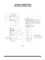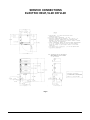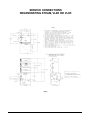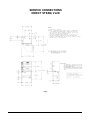
1
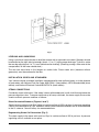
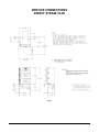
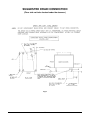
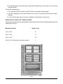
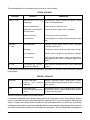
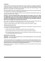
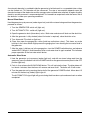
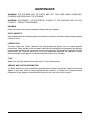
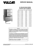
INSTALLATION &
OPERATION MANUAL
VL SERIES FOOD STEAMERS
GAS, ELECTRIC, DIRECT STEAM
OR REGENERATIVE
MODEL
VL2GPS
VL2GMS
VL2GAS
VL2GSS
VL3GPS
VL3GMS
VL3GAS
VL3GSS
VL2EPS
VL2EMS
VL2EAS
VL2ESS
VL3EPS
VL3EMS
VL3EAS
VL3ESS
ML-52733
ML-52734
ML-52735
ML-52736
ML-52737
ML-52838
ML-52739
ML-52740
ML-52741
ML-52742
ML-52743
ML-52744
ML-52745
ML-52746
ML-52747
ML-52748
VL2DPS
VL2DMS
VL2DAS
VL2DSS
VL3DPS
VL3DMS
VL3DAS
VL3DSS
VL2RPS
VL2RMS
VL2RAS
VL2RSS
VL3RPS
VL3RMS
VL3RAS
VL3RSS
ML-52749
ML-52750
ML-52751
ML-52752
ML-52753
ML-52754
ML-52755
ML-52756
ML-52757
ML-52758
ML-52759
ML-52760
ML-52761
ML-52762
ML-52763
ML-52764
For additional information on Vulcan-Hart Company or to locate an authorized
parts and service provider in your area, visit our website at www.vulcanhart.com
VULCAN-HART
COMPANY,
P.O.
BOX
696,
LOUISVILLE,
KY
40201-0696,
TEL.
(502)
778-2791
FORM 30525 Rev. C (Jan. 2003)
IMPORTANT FOR YOUR SAFETY
THIS MANUAL HAS BEEN PREPARED FOR PERSONNEL QUALIFIED TO INSTALL GAS
EQUIPMENT, WHO SHOULD PERFORM THE INITIAL FIELD START-UP AND
ADJUSTMENTS OF THE EQUIPMENT COVERED BY THIS MANUAL.
POST IN A PROMINENT LOCATION THE INSTRUCTIONS TO BE FOLLOWED IN THE
EVENT THE SMELL OF GAS IS DETECTED. THIS INFORMATION CAN BE OBTAINED
FROM THE LOCAL GAS SUPPLIER.
IMPORTANT
IN THE EVENT A GAS ODOR IS DETECTED, SHUT DOWN
UNITS AT MAIN SHUTOFF VALVE AND CONTACT THE LOCAL
GAS COMPANY OR GAS SUPPLIER FOR SERVICE.
FOR YOUR SAFETY
DO NOT STORE OR USE GASOLINE OR OTHER FLAMMABLE
VAPORS OR LIQUIDS IN THE VICINITY OF THIS OR ANY
OTHER APPLIANCE.
WARNING: IMPROPER INSTALLATION, ADJUSTMENT,
ALTERATION, SERVICE OR MAINTENANCE CAN CAUSE
PROPERTY DAMAGE, INJURY OR DEATH. READ THE
INSTALLATION, OPERATING AND MAINTENANCE
INSTRUCTIONS THOROUGHLY BEFORE INSTALLING OR
SERVICING THIS EQUIPMENT.
IN THE EVENT OF A POWER FAILURE, DO NOT ATTEMPT TO
OPERATE THIS DEVICE.
KEEP AREA AROUND OVEN CLEAR OF COMBUSTIBLES. DO
NOT OBSTRUCT COMBUSTION AND VENTILATION OPENINGS
ON THE OVEN.
© VULCAN-HART COMPANY, 2003
–2–
TABLE OF CONTENTS
GENERAL .............................................................................................................................................4
INSTALLATION ....................................................................................................................................4
Unpacking .......................................................................................................................................4
Location ...........................................................................................................................................4
Assembly .........................................................................................................................................5
Leveling and Anchoring ..................................................................................................................6
Installation Codes and Standards ..................................................................................................6
Steam Connections .........................................................................................................................6
Plumbing Connections ....................................................................................................................7
Gas Connections ............................................................................................................................8
Testing the Gas Supply System ....................................................................................................8
Flue Connections ............................................................................................................................9
Electrical Connections ....................................................................................................................9
Electrically Heated Generator Connections ..................................................................................9
Service Connections Diagrams ...................................................................................................10
OPERATION .......................................................................................................................................16
Lighting the Pilot (Gas Steamers) ................................................................................................16
Selection of Pans for Steam Cooking .......................................................................................... 17
Starting the Steam Generator ...................................................................................................... 19
Steam Cooking .............................................................................................................................. 20
Cleaning .........................................................................................................................................22
Generator Blow-Down .................................................................................................................. 22
MAINTENANCE ..................................................................................................................................24
Deliming .........................................................................................................................................24
Door Gaskets ................................................................................................................................ 24
Lubrication ..................................................................................................................................... 24
Flue ................................................................................................................................................24
Service and Parts Information ...................................................................................................... 24
–3–
Installation, Operation and Care of
VL SERIES GAS, ELECTRIC, DIRECT STEAM
OR REGENERATIVE FOOD STEAMERS
SAVE THESE INSTRUCTIONS
GENERAL
Vulcan-Hart suggests that you thoroughly read this entire manual and carefully follow all of the
instructions provided.
Your Vulcan Model VL Food Steamer is produced with quality workmanship and material. Its boiler is
fully automatic with the heat input controlled by preset pressure switches. A solenoid valve feeds
makeup water as needed.
The steamer is equipped with adjustable feet.
Proper installation, usage and maintenance of your food steamer will result in many years of
satisfactory performance.
INSTALLATION
UNPACKING
This food steamer was inspected before leaving the factory. The transportation company assumes full
responsibility for safe delivery upon acceptance of the shipment. Immediately after unpacking, check
for possible shipping damage. If the food steamer is found to be damaged, save the packaging material
and contact the carrier within 15 days of delivery.
LOCATION
Before installing, verify that the electrical service or gas supply (natural or propane) agrees with the
specifications on the rating plate located on the boiler access door. If the supply and equipment
requirements do not agree, do not proceed with the installation. Contact your dealer or Vulcan-Hart
immediately.
Position the food steamer in its final location. Check that there are sufficient clearances to service the
controls, for door swings, etc., so there will be no problem in making the required supply and drain
connections. Recommended clearances are 18" (46 cm) on the sides and back, and 36" (91 cm) in the
front.
Allow enough space between any other piece of equipment or a wall for access. All service on the
compartment controls begins by removing the panel on the left side of the food steamer.
–4–
For Gas Appliances Only
Keep the food steamer free and clear from all combustible substances. Minimum clearance from
combustible and noncombustible construction is 6" (15 cm) at the rear and 6" (15 cm) at each side.
Do not obstruct the air flow into and around the food steamer. This air flow is necessary for proper
combustion of gases and for ventilation of the food steamer. Provisions for ventilation of incoming air
supply for the equipment in the room must be in accordance with National Fuel Gas Code ANSI Z223.1
(latest edition).
Do not obstruct the flow of flue gases from the flue duct (when so equipped) located on the rear (or
sides) of the food steamer. It is recommended that the flue gases be ventilated to the outside of the
building through a ventilation system installed by qualified personnel.
For steamers equipped with casters, the installation shall be made with a connector that complies with
the Standard for Connectors for Movable Gas Appliances, ANSI Z21.69 (latest edition), and a quickdisconnect device that complies with the Standard for Quick-Disconnect Devices for Use With Gas
Fuel, ANSI Z21.41 (latest edition). Provide a gas line strain relief to limit the movement of the steamer
without depending on the connector and any quick-disconnect device or its associated piping to limit
the steamer movement. Attach the strain relief to the rear of the steamer (Fig. 1).
Fig. 1
If disconnection of the gas line strain relief is necessary, turn off gas supply before disconnection.
Reconnect this strain relief before turning the gas supply on and returning the steamer to its originally
installed position.
ASSEMBLY
The steamer is shipped as a complete unit, and no assembly is required. However, the burner shipping
restraint must be removed (Fig. 2). To do this, remove two hex nuts and two washers off the weldstuds
on the boiler shell.
–5–
Fig. 2
LEVELING AND ANCHORING
Using a spirit level, adjust the feet to level the steamer left to right and front to back. Steamers should
be elevated on the right side just enough (about 1/16" to 1/8") to give proper drainage. To do this, rotate
the rear leg adjusting nut 1 to 1 1/2 turns clockwise after leveling. (Check by pouring a little water in the
compartment; all the water should drain.)
The rear feet have holes in the flanges for anchor bolts. Direct steam units (steamers without
generators) must be anchored to the floor.
INSTALLATION CODES AND STANDARDS
Your Vulcan steamer should be installed in accordance with state and local codes, or in the absence
of local codes, with National Fuel Gas Code, ANSI-Z223.1 (latest edition), NFPA Standard #96 (latest
edition), and National Electrical Code ANSI/NFPA 70 (latest edition).
STEAM CONNECTIONS
Provide dry steam to the inlets. If the steam is heavy with condensate, install a ball float trap before the
pressure regulator valve. To ensure rapid heat-up of heavy cold loads, the steam supply line must be
sized to maintain pressure and flow as follows:
Direct-Connected Steamers (Figures 6 and 7)
Supply steam at a pressure of 20 to 100 psi at a minimum flow of 125 lb. per hour. A pressure regulating
valve is furnished and set at 5 psi. Additional steam kettles and kettle modules can be interconnected
to the VL steamer. Consult factory for recommendations.
Regenerating Steam Coil Generators (Fig. 5)
The steam supply to the steam coils must be 15 psi at a minimum flow of 125 lb. per hour. A pressure
regulating valve is available as an option.
–6–
PLUMBING CONNECTIONS (Figures 3 through 7)
WARNING: PLUMBING CONNECTIONS MUST COMPLY WITH APPLICABLE SANITARY, SAFETY
AND PLUMBING CODES.
Water Supply Connection
The water filter, provided, must be installed in the water supply line going to the filtered water inlet or
your steamer warranty may be voided. For incoming water supply line pressures, refer to the water filter
manual shipped with the water filter. Follow the recommendations contained in it. Water pressure to the
steamer should be 20 to 60 psi.
Water Requirements
Proper water quality can improve the taste of the food prepared in the steamer, reduce liming in the
steam generator and extend equipment life. Local water conditions vary from one location to another.
Ask your municipal water supplier for details about your local water supply before installation.
Recommended water parameters are included in the water filter manual shipped with the steamer;
follow the recommendations contained in it.
Presence of sediment, silica, excess chlorides or other dissolved solids may lead to a recommendation
for alternate form(s) of water treatment. Be sure to test the water with the test strip and register the
results using the registration card or by visiting vulcanhart.com.
Filtered Water Connection—Used for boiler feed water.
Unfiltered Water Connection—Used as cold water condenser on boiler blow-down line.
Direct-connected kettle modules have a separate water inlet for the swing spout faucet. Minimum water
pressure of 20 psi is required at the connections.
Drain Connection(s)
Drain connections must be the open air gap type. Provide a suitable floor sink with a minimum depth
of 12" (30 cm) (see Fig. 8). The floor sink is NOT to be located under the steamer.
CAUTION: In order to avoid any back pressure in the steamers, do not connect solidly to any
drain connection.
Draining Requirements
Temperatures in the boiler can reach as high as 240°F (116°C). Local codes will require that the
temperature of the drain water be 140°F (60°C) or lower. At the end of the day when purging the boilers,
some provision for lowering the water temperature must be provided by the user or installer to meet this
code requirement.
–7–
GAS CONNECTIONS (Fig. 3)
CAUTION: All gas supply connections and any pipe joint compound used must be resistant to
the action of liquefied petroleum gases.
Codes require that a gas shutoff valve be installed in the gas line ahead of the steamer.
Connect the gas supply line to the gas valve on the steamer. Make sure the pipes are clean and free
of obstructions, dirt and piping compound.
The gas line must be capable of delivering gas to the steamer without excessive pressure drop at the
rate specified on the nameplate. Suggested gas line pressure is 7" W. C. for natural gas and 11" Water
Column for propane gas.
WARNING: PRIOR TO LIGHTING, CHECK ALL JOINTS IN THE GAS SUPPLY LINE FOR LEAKS.
USE SOAP AND WATER SOLUTION. DO NOT USE AN OPEN FLAME.
TESTING THE GAS SUPPLY SYSTEM
When test pressures exceed 1/2 psi (3.45 kPa), the steamer and its individual shutoff valve must be
disconnected from the gas supply piping system.
When test pressures are 1/2 psi (3.45 kPa) or less, the steamer must be isolated from the gas supply
system by closing its individual manual shutoff valve.
–8–
FLUE CONNECTIONS
DO NOT obstruct the flow of flue gases from the flue located on the rear of the steamer. It is
recommended that the flue gases be ventilated to the outside of the building through a ventilation
system installed by qualified personnel.
Information on the construction and installation of ventilating hoods may be obtained from the standard
for the Removal of Vapors from Commercial Cooking Equipment, NFPA No. 96 (latest edition),
available from the National Fire Protection Association, Batterymarch Park, Quincy, MA 02269.
ELECTRICAL CONNECTIONS (Figures 3 through 7)
WARNING: ELECTRICAL AND GROUNDING CONNECTIONS MUST COMPLY WITH THE
APPLICABLE PORTIONS OF THE NATIONAL ELECTRICAL CODE AND/OR OTHER LOCAL
ELECTRICAL CODES.
WARNING: DISCONNECT THE ELECTRICAL POWER TO THE MACHINE AND FOLLOW
LOCKOUT / TAGOUT PROCEDURES.
All steamers, except the direct steam model, are connected to 110/120 V, 50/60 Hz, 1-phase supply
through the pigtail leads in the supply junction box located next to the boiler control box. The junction
box for the direct steam model is located on the underside of the cabinet top. Use copper wire suitable
for at least 75°C temperature. Connect a grounding wire to the ground lug in the junction box.
This connection is not required on electrically heated generators when equipped with an optional
transformer, or on direct steam models with manual controls.
ELECTRICALLY HEATED GENERATOR CONNECTIONS (Fig. 4)
The voltage and phase of the supply circuit and the rating of the steamer must be in agreement. Make
the electrical supply connection in the junction box on the steamer. The supply wiring and circuit
protection must be adequate for the kilowatt load of the steamer. Connect a grounding wire to the ground
lug in the junction box. Use copper wire of the size and temperature rating marked on the supply label.
Refer to the following wiring diagrams.
Wiring Diagram For:
Located On:
Heat Circuit
Cover of control box housing the heating elements.
Boiler Control
Inside of access door to base.
Compartment Controls
Left compartment side panel.
–9–
SERVICE CONNECTIONS
GAS HEAT, VL2G OR VL3G
Fig. 3
– 10 –
SERVICE CONNECTIONS
ELECTRIC HEAT, VL2E OR VL3E
Fig. 4
– 11 –
SERVICE CONNECTIONS
REGENERATING STEAM, VL2R OR VL3R
Fig. 5
– 12 –
SERVICE CONNECTIONS
DIRECT STEAM, VL2D
Fig. 6
– 13 –
SERVICE CONNECTIONS
DIRECT STEAM, VL3D
Fig. 7
– 14 –
SUGGESTED DRAIN CONNECTION
(Floor sink not to be located under the steamer.)
Fig. 8
– 15 –
OPERATION
WARNING: THE STEAMER AND ITS PARTS ARE HOT. USE CARE WHEN OPERATING,
CLEANING AND SERVICING THE STEAMER.
LIGHTING THE PILOT (Gas Steamers)
Before lighting the pilot, both the burner and the pilot must have been off for at least 5 minutes.
Gas to both the burners and to the pilot is automatically cut off if the pilot flame goes out. Added
protection is provided by a pressure switch which cuts the heat off when pressure reaches 6 psi (for
5 psi generator) or 15 psi (for 15 psi generator). A pressure relief valve is also provided on all models.
Steamers with Continuous Pilots:
1. Turn ON/OFF switch (upper left of generator cabinet) to OFF. Be sure gas to the steamer is turned
on.
2. Turn the combination control knob to PILOT. Hold a flame to ignite the pilot while depressing the
knob of the combination valve completely. Keep the knob depressed for about 1 minute after the
pilot is lit.
3. Release the knob. The pilot should continue burning. If not, wait 5 minutes; then repeat Step 2.
4. Turn the knob counterclockwise to ON.
To Shut the Steamer Down:
1. Turn the gas service valve and the ON/OFF switch OFF.
2. Close the water inlet valve.
Steamers with Intermittent Pilots:
1. Turn combination valve knob counterclockwise until it stops at the ON position.
2. Turn boiler ON/OFF switch to the ON position (light on).
3. The electrode will begin sparking, and the pilot will light.
4. Look at pilot flame to make sure the pilot light has lit. If not, turn boiler switch OFF, wait 5 minutes
and repeat Step 2. If after the third attempt the pilot does not light, call for service.
5. The pilot light will remain lit as long as the boiler ON/OFF switch is in the ON position.
– 16 –
6. The cycling pressure switch will open and close the combination valve, which, in turn, will cycle
the main burner.
To shut the steamer down:
1. Turn the boiler ON/OFF switch to the OFF position to extinguish the pilot light.
2. Turn the combination valve knob clockwise until it stops to stop pilot light and main burners
function.
3. To shut off pilot light and main burners completely, close the gas service valve.
SELECTION OF PANS FOR STEAM COOKING
Vulcan steamer compartments are designed to accept combinations of the following perforated or solid
cooking pans (Fig. 9):
Maximum Quantity
Depth of Pan
(4) 12" x 20"
6"
(6) 12" x 20"
4"
(8) 12" x 20"
21/2"
(6) 18" x 26" (after removal of center support)
1"
Fig. 9
– 17 –
The following chart lists the types of pans to use for various foods:
FRESH PRODUCT
TYPE PAN
Solid 12" x 20"
Perforated
12" x 20"
18" x 26"
PRODUCT
EXAMPLES
Dehydrated Fruits and
Vegetables.
Dried peaches, prunes, apples and apricots. Sliced
onions and sliced potatoes.
Cereals and Puddings.
Cream of wheat, rolled oats, rice.
Vegetables—to be cooked in
their own liquid.
Broccoli, brussels sprouts, peas, cauliflower.
Meats and Poultry.
To save broth, cook in solid pans.
Canned Foods.
Place opened can in solid pan or pour contents into the
pan.
Root Vegetables*
Potatoes, carrots, beets, turnips, onions, parsnips,
rutabagas, oyster plant.
Sausages.
Frankfurters, weiners, garlic sausages, meat sausages.
Leaf Vegetables*
Spinach, kale, turnip greens, collard greens, cabbage.
Miscellaneous.
Corn on the cob, green beans, celery and celery hearts,
green pepper shells, squash, mushrooms. Eggs in their
shells.
Precooked and Partially
Cooked Sliced Meats.
Ham, meat loaf, roast beef, chicken, turkey, hamburger
patties.
*If you wish to save liquids from root or leaf vegetables, place them in a solid pan, or place a solid pan under the
perforated pan.
FROZEN PRODUCT
Perforated
Frozen Vegetables.
Loosen
and
spread
vegetable.
Broccoli, asparagus spears, green beans, carrots,
brussels sprouts, turnips, potatoes, cut corn, lima beans,
peas, squash.
Solid
Precooked Dishes.
Remove wrapping and place
in pan.
All precooked dishes, such as beef goulash, chicken
fricassee, etc., which cannot be cooked in the containers
in which they are packed.
Separate frozen food packs into smaller chunks.
If unpacked, precooked frozen dishes require more than 15 minutes to cook, cover the pan. When a
cover is used, about one-third more cooking time is required. This is true only of foods in either portion
size or in larger sizes which cannot be cooked in the covered containers in which they are packed.
Cooking time required for frozen foods depends upon the amount of defrosting required. If time permits,
allow the frozen foods to partially thaw overnight in a refrigerator. This will reduce their cooking times.
– 18 –
STARTING THE STEAM GENERATOR
Do not feed water into a heated generator which has run dry. If for any reason the generator runs dry,
turn all services (electricity, gas or steam) off and wait until the generator cools to room temperature.
Local water conditions may cause excessive boiler scale build-up and cause the boiler and compartment
controls to operate incorrectly. (See water quality requirements under Plumbing Connections in this
manual.) Contact your local water conditioner dealer for additional information on local water conditions.
Proper periodic maintenance must be performed. Contact your local Vulcan-authorized servicer.
Check the gauge glass daily, before the power switch is turned on, to make sure the water level is about
in the middle of the glass. If water is not at the proper level in the gauge glass, contact your local Vulcanauthorized servicer.
All needed utility services (including water, electricity and, when specified, gas or steam) must be
turned on. If the generator is gas heated, the gas pilot must be burning.
The generator drain (or blow-down) valve must be closed.
Keep both valves (one each at the top and bottom) of the gauge glass open at all times.
The water inlet service valve must be open. Close this valve only for service or for a long shutdown.
To start the steam generator, open the door on the lower left side. Press the top half of the rocker switch
labeled AUTOMATIC FILL to ON. When the water level is about halfway up in the gauge glass, press
the top half of the switch labeled POWER to ON. The amber light indicates that power is on. It will stay
lit until the boiler is at operating pressure. The compartment pressure gauge, located on the
compartment control panel, will indicate about 5 to 6 psi. Allow about 15 minutes for heat-up time.
To turn the steam generator off, turn POWER and AUTOMATIC FILL switches to OFF.
– 19 –
STEAM COOKING
Refer to the Steam Cooking with Vulcan Kettles and Steamers booklet (packed with your steamer) for
suggested cooking times of various foods. All cooking times are approximate because size, weight,
pan loading and product quality will affect steamer cooking times. Use these suggestions and then
adjust your cooking times to your own requirements.
1. Prepare vegetables, fruits, meats, seafood and poultry as you would for steam cooking or cooking
in water (clean, separate, cut, remove stems, etc.). Place in pan.
2. Place loaded pans in the compartment and close the compartment door. Turn the door screw
handle clockwise to seal the door gasket. Normal pressure will seal the compartment. However,
until it is seasoned, a new gasket may require additional pressure after it becomes heated. When
the pressure gauge reaches maximum pressure (41/2 to 51/2 psi), turn the handle enough to stop
the leakage. (The pressure gauge shows steam pressure in the steam supply pipe, not the
pressure in the compartment.)
3. The timer knob must be turned to 5 minutes or beyond to trip the switches. The knob may then
be turned back to a lower setting if a shorter cooking cycle is desired.
4. Pull the steam control handle forward until it latches. The door latch cannot be opened when the
steam control handle is pulled forward. Air is automatically vented from the compartment when
steam enters the compartment. The escaping air causes a hissing sound, which you will hear
during the early part of the cycle.
5. Proceed with the cooking operation, using the instructions below for the controls applicable to
your steamer.
Manual Compartment Controls
1. Set the timer to the sum of the desired cooking time plus some minutes allowed for preheat. The
preheat allowance will generally be 5 to 10 minutes. It will vary with the type, size, temperature
and condition (frozen or thawed) of the load, and must be determined from experience.
2. Pull the compartment control arm forward and lock it down by pulling the arm down. This closes
the drain and allows steam to enter the compartment.
3. When the timer bell rings (5 to 10 seconds), lift the arm and give it a slight push to the rear. An
internal spring will automatically pull the arm to the rear, shutting off the steam supply and opening
the drain.
4. Wait about 30 to 45 seconds for the steam to exhaust. Then loosen the screw handle on the
compartment door, allowing moisture to escape. After a few seconds, move the latch paddle to
the left and then open the door and remove pans of food.
Standard Automatic Controls
1. Set the timer to the sum of the desired cooking time plus some minutes allowed for preheat. The
preheat allowance will generally be 5 to 10 minutes. It will vary with the type, size, temperature
and condition (frozen or thawed) of the load, and must be determined from experience.
2. Pull the compartment control arm forward and lock it by pulling the arm down. This closes the drain
and allows steam to enter the compartment.
3. Press the top half of the red switch located under the timer. This starts the timer. The balance of
the cooking time sequence is automatic.
– 20 –
4. When the timer reaches zero, the arm automatically moves to the rear, shutting off the steam
supply and opening the drain. The compartment will exhaust for about 1 minute; then the
continuous buzzer will sound, indicating the end of the cooking cycle.
5. Turn the steamer off by pressing the bottom half of the red switch. Then loosen the door screw
handle, allowing moisture to escape. After a few seconds, move the latch paddle to the left and
then open the door and remove pans of food.
Deluxe Automatic Controls
1. Set timer to the desired cooking time. Pull the compartment control arm forward and lock it by
pulling the arm down. This closes the drain and allows steam to enter the compartment.
2. Press the top half of the red switch located under the timer. This starts the timer.
A feature of this deluxe control is load-compensated automatic timing. With this feature, the red
light will not light immediately. It will come on and the timer will start after the interior compartment
temperature reaches 180°F (82°C) or above (the temperature at which preheat is complete or
when defrosting is complete). For a small food load, the time wait before the timer starts might be
a minute or less. For a large food load, the time wait could be up to 4 or 5 minutes.
3. When the timer reaches zero, the arm automatically moves to the rear, shutting off the steam
supply and opening the drain. The compartment will exhaust for about 1 minute; then the
continuous buzzer will sound, indicating the end of the cooking cycle.
4. Turn the steamer off by pressing the bottom half of the red switch. Then loosen the door screw
handle, allowing moisture to escape. After a few seconds, move the latch paddle to the left and
then open the door and remove pans of food.
Pre-Vent Steam Mizer Automatic Controls
1. Set the timer to the desired cooking time. Pull the compartment control arm forward and lock it by
pulling the arm down. This allows steam to enter the compartment.
2. Press the top half of the red switch (located under the timer) to start the timer.
The red light will not light immediately. It will come on and the timer will start when the interior
compartment temperature reaches 180°F (82°C) or above (the temperature at which preheat is
complete or when defrosting is complete).
During the preheat/defrost period, the compartment drain is open under full free vent to remove
any air and condensate. At 180°F, the compartment drain closes, the timer starts and the red light
comes on. During the cooking cycle, the compartment will reach 5 to 6 psi. Also, limited venting
takes place through the compartment drain, continuing to allow the removal of condensate and
any residual air.
3. When the timer reaches zero, the arm automatically moves to the rear, shutting off the steam
supply and opening the drain. The compartment will exhaust for about 1 minute; then the
continuous buzzer will sound, indicating the end of the cooking cycle.
4. Turn the steamer off by pressing the bottom half of the red switch. Then loosen the door screw
handle, allowing moisture to escape. After a few seconds, move the latch paddle to the left and
then open the door and remove pans of food.
– 21 –
CLEANING
Allow the steamer to cool and clean the compartment at the end of each day, or between cooking cycles
if necessary. Using warm soapy water and a cloth or sponge, clean the exposed bead of each door
gasket after each day's use. Follow with a warm water rinse to remove all traces of detergent. Then
wipe with a soft, dry cloth. This will extend gasket life.
When cleaning the bottom of the compartment, wipe all solids away from the drain opening, especially
any large particles, to prevent possible clogging of the drain.
If the water in the sight glass becomes extremely murky, the generator should be blown down (see
Generator Blow-Down) and/or cleaned.
CAUTION: Leave the compartment door slightly open when the steamer is not in use. When
the compartment is idle, never latch the door and apply pressure to the door gasket. Leaving
the gasket under pressure can cause permanent deformation, which will greatly shorten the
gasket life. Never apply food oils or petroleum lubricants directly to the door gasket. Petroleum
base solvents and lubricants will shorten door gasket life.
Once a week, thoroughly clean the exposed surfaces (sides, front, door, top) with a damp cloth and
polish with a soft, dry cloth. To remove discolorations, use a nonabrasive cleaner.
The boiler should be left empty only when it will not be used for several weeks or longer.
Cooking Compartment Drains
It is important to keep the cooking compartment drains clear so condensate and other moisture can
drain freely from the cooking compartment.
1. Inspect the drains daily for blockages by pouring water into the compartment.
2. Clean the perforated drain strainer at least daily, and more frequently if required.
3. After cooking grease-producing foods, pour one-half gallon of soapy water down the drain and
rinse with one-half gallon of hot clear water.
GENERATOR BLOW-DOWN
WARNING: THE WATER BEING DRAINED IS HOT AND UNDER PRESSURE. USE CARE WHEN
SERVICING THE GENERATOR.
To prevent malfunction of controls and clogging, it is essential to flush (blow down) the generator every
day. This will flush out the accumulated minerals (left from the feed water) and aid in preventing internal
scale build-up which, in time, would interfere with proper generator operation. Failure to blow down the
generator every day may void the warranty applying to the controls.
The presence of minerals in suspension is indicated by a murky or milky condition in the first portion
of the water drained.
– 22 –
An automatic descaler is provided inside the generator to hold minerals in a suspended state so they
can be flushed out. This descaler will be consumed. The rate of consumption depends upon the
chemical makeup of the feed water and the average volume of feed water required. A regular monthly
check by service personnel is recommended until it is learned from experience what the normal life of
the descaler is under your operating conditions.
Manual Blow-Down
Heat the generator up to pressure (amber signal out); and with no steam being used from the generator,
proceed as follows:
1. Turn the GENERATOR switch off (light out).
2. Turn AUTOMATIC FILL switch off (light out).
3. Open the generator drain (blow-down) valve. Both water and steam will drain out the drain line.
4. After the generator is fully drained (about 3 minutes is required), close the drain valve.
5. Turn Automatic Fill switch on (light on).
6. Close, then open the gauge glass valves (both top and bottom valves). This clears any scale
build-up in the valves which might prevent the gauge glass from showing the true water level in
the generator.
7. After the water is halfway up in the gauge glass, turn the POWER switch back on and observe
amber HEAT ON light. It should come on when a safe water level is again reached. This indicates
proper operation of the low-water cutoff device.
Automatic Blow-Down
1. Heat the generator up to pressure (amber light out); and with no steam being used from the
generator, press the bottom half of the POWER switch on the generator control panel to the OFF
position (light out).
2. Push in, then release the BLOW DOWN button. This will activate the timer. The blow-down will
last about 4 minutes; then the timer will reverse and reset itself. The boiler will fill with water.
3. Turn the generator on by pressing the top half of the generator POWER switch. Allow about 15
minutes for the heat-up (amber) light to go off.
The AUTOMATIC fill signal light will go out during the blow-down cycle and come back on when
completed.
– 23 –
MAINTENANCE
WARNING: THE STEAMER AND ITS PARTS ARE HOT. USE CARE WHEN OPERATING,
CLEANING AND SERVICING THE STEAMER.
WARNING: DISCONNECT THE ELECTRICAL POWER TO THE MACHINE AND FOLLOW
LOCKOUT / TAGOUT PROCEDURES.
DELIMING
Refer to the water filter manual shipped in the box with your steamer.
DOOR GASKETS
After compartments with new door gaskets have been in service for a few days, tighten the door gasket
retainer screws.
LUBRICATION
The door screw was factory lubricated with high-temperature grease, but will require periodic
relubrication. When the door screw is properly lubricated, the hand pressure required to seal the door
is greatly reduced and the life of the screw and nut are lengthened. The frequency of lubrication should
depend upon use. Lubricate monthly at first and let experience determine the frequency. A hightemperature door screw grease can be obtained from Vulcan-Hart Company.
FLUE
When cool, annually check the flue to be sure it is free of obstructions.
SERVICE AND PARTS INFORMATION
To obtain service and parts information concerning this steamer, contact the Vulcan-Hart Service
Agency in your area (refer to listing supplied with the steamer), or Vulcan-Hart Company Service
Department at the address or phone number shown on the front cover of this manual.
FORM 30525 Rev. C (Jan. 2003)
– 24 –
PRINTED IN U.S.A.