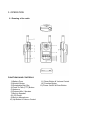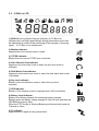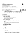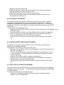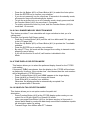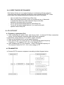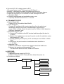
1
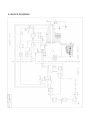
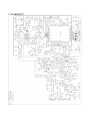
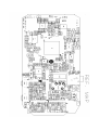
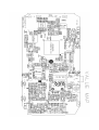
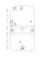
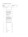
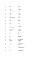
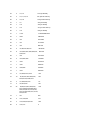
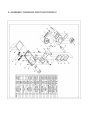
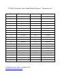
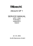
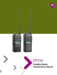
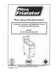
Tectalk
SERVICE MANUAL
2-WAY PORTABLE
HANDHELD
PMR 446 RADIO
Nov. 07. 2001
ALAN Electronics GmbH
CONTENT
1. GENERAL
1.1 General
1.2 Characteristic
1.3 Composition
2. SPECIFICATION
2.1 General Specification
2.2 Electrical Specification
3. OPERATION
3.1 Key Name
3.2 ICONS on LCD
3.3 Key Functions
3.4 Setting and Operation
4. ADJUSTMENT
4.1 Frequency synthesizer
4.2 Transmitter
4.3 Transmitter Test
4.4 Receiver
4.5 Receiver Test
4.6 Symptoms, check point & Correction
5. DESCRIPTION OF RADIO CIRCUIT
5.1 Frequency Synthesizer
5.2 Receiver
5.3 Transmitter
6. BLOCK DIAGRAM
7. SCHEMATIC
8. COMPONENT PARTLIST
9. ASSEMBLY DRAWING AND PHOTOGRAPH
10. CHANNEL DATA (With Sub-channel data)
1. GENERAL
1.1 GENERAL
This equipment, Tectalk is called 2 way portable handheld radios.
The frequency range is 446.00625 to 446.09375MHz, UHF operating channels for
Europe-wide used 2 way portable radios according to PMR-446 Standard.
1.2 CHARACTERISTIC
a) All active device in this radio is composed of semiconductor and high
density IC.
b) To design this radio in compact and weight approximately 140g including
battery.
C) CPU of this equipment is HD4048812B from HITACHI.
d) It's power can operate by use of alcaline 4 cell (1.5V AAA) battery.
1.3 COMPOSITION
This radio is composed of following.
a) Transmitter (W/Antenna)
b) Belt clip
2. SPECIFICATION
2.1 GENERAL SPECIFICATIONS
a) Frequency Range : 446.00625 to 446.09375 MHz
b) Output Impedance : 50 Ohms Unbalanced
c) Modulation Type : 8K50F3E
d) Communication Mode : Simplex
e) Channel Capacity : 8 channel
f) Channel spacing : 12.5 KHz
g) Power : 6.0V(ALCA 1.5V x 4AAA)
h) Battery Life : ALCA.1000mAh > about 35hours
NI-MH 600mAh > about 22hours
( TX 5% ,RX 5% ,Standby 90% )
i) Operating Temperature : -20°C to +55°C
j) Dimension : 95.5(H)x 50(W)x 26(D)mm
k) Weight : 120g(with Battery)
2.2 ELECTRICAL SPECIFICATION
a) TRANSMITTER
1) Output power : Max. 0.5W
2) Frequency Stability : +/- 5PPM (-20°C to+55 °C)
3) Modulation Method : FM
4) Oscillation Method : PLL SYNTHESIZER
5) Max. Frequency Modulation : < +/- 2.5 KHz (with tone)
6) Cooling Method : air-cooling Method
7) Spurious Emission TX : < -36dBm
8) FM Hum/Noise : > 40dB(1kHz 60% modulation)
9) Distortion : < 5% (1kHz 60% modulation)
10) Tx Audio Response : 6dB /OCT +/- 3dB PRE-EMPHASIS(300Hz to 2.5kHz)
b) RECEIVER
1) Receive Method : Double Super Heterodyne
2) Receive Sensitivity : -118dBm up (20dB SINAD W/CCITT)
3) Squelch Sensitivity : -120 to -130dBm (Audio on/off point)
4) Bandwidth : > 8.5KHz
5) Adjacent channel rejection : > 55dB
6) Local Frequency Stability : +/- 5PPM (-20°C to +55°C)
7) Spurious Response Rejection : > 65dB
8) Audio output : 200mW(8 Ohms load THD 10%)
9) Distortion : < 5% (1kHz 60% Modulation)
10) RX Audio Response : 6dB/OCT +/- 10dB DE-EMPHASIS(300Hz to 2.5kHz)
11) S/N Ratio : > 40dB(1kHz 60% modulation)
12) IF :
13) Local Frequency :
1'st IF = 21.7MHz
2'nd IF = 450kHz
1st Local Frequency = fc - 21.7MHz
2nd Local Frequency = 21.25MHz
3. OPERATION
3.1 Drawing of the radio
FUNCTIONS AND CONTROLS
1) Battery Door
2) Monitor Button
3) Detachable Belt Clip
4) Push-To-Talk (PTT) Button
5) Antenna
6) External Mic / Speaker
7) Built-in Speaker
8) LCD Panel
9) Built-in Microphone
10) Up Button & Volume Control
11) Down Button & Volume Control
12) Function Button
13) Power On/Off & Enter Button
3.2 ICONS on LCD
1) RSSI (Receiving Signal Strength Indicator) or TX Bar Icon
Indicates the receiving signal strength during transmission and it can
be indicated the number of bar according to the strength of receiving
signal. It (TX Bar) is not transformed.
2) Monitor Indicator
Appears when the monitor button is used.
3) CTCSS Indicator
Blinks when the correct CTCSS tone is entered.
4) Auto Channel Scan Indicator
Appears in the auto scan mode or when the auto scan mode is
activated.
5) Dual Watch Scan Indicator
Appears in dual watch scan mode or when the dual watch scan mode
is activated.
6) Key Lock Indicator
Blinks in auto lock selection mode or when the key lock is
activated.
7) VOX Indicator
Blinks in VOX selection mode or appears when VOX is activated.
8) Battery Level Indicator
Battery Level Meter indicates the remaining battery strength.
Blinking when the Battery charge strength is Low-cell only and then red
LED Blinking at every 5sec.
When the TOT Penalty is Warning Beeping at initial activation and not
Transmit at 10sec.
9) Tx Indicator
Appears when a signal is being transmitted.
10) Rx Indicator
Appears when a signal is being received.
11) Large Segment Display
Indicates the channel number in use at the normal mode.
When the Function Button is pressed, it Displays the function menu
in sequence :
CH / ctc / SC / dW / VO / Vdt / ALo / CAL / tON / tAL / bEP
12) Small Segment Display
Displays the CTCSS tone option at the normal mode.
CTCSS option is displayed in Hz.
Displays the SUBMENU of each MENU in the function mode.
(e.g. CH 1 to 8 / ctc: 1 to 38, OFF / SC: up, dn, OFF / dW: 1 to 8, OFF /
VO: High, Mid, Low, OFF / Vdt: 5sec, 3sec, 2sec, 1sec / Alo: OFF, Auto /
CAL number: 1 to 7, OFF / tON: no, Freq / tAL: On,OFF / bEP: On,OFF)
3.3 Key Function
3.3-1 ENTER BUTTON (#13)
1) Short Touch - Power On
- Press this button (#13) briefly to turn the unit on.
A short confirming melody will play.
2) Long Touch - Power Off
Press this button (#13) for longer than 1.5 seconds to turn the
unit off.
Press it to confirm the required option for respective functions
during function edit mode.
3.3-2 FUNCTION BUTTON (#12)
1) Short Touch
-
Press this button briefly to enter function edit mode in standby
mode.
2) Long Touch
-
Press for longer than 1.5 seconds to activate the KEY LOCK in the
standby mode.
Please note all buttons will be disabled except the Monitor
Button (#2) and PTT Button (#4) will remain fully operational.
3.3-3 UP BUTTON (#10)
1) Short Touch
-
In the standby mode, press this button briefly to move to the next higher
main volume level.
In the function edit mode, press briefly to shift from the current option
in each submenu to the next option in the same submenu.
2) Long Touch
-
Pressing this button for more than 1.5 seconds will allow you to navigate
at a more rapid rate through different volume level in the standby mode or
through different menus in the function edit mode.
mode.
3.3-4 DOWN BUTTON (#11)
1) Short Touch
-
In the standby mode, press this button briefly to move to the previous
lower main volume level.
In the function edit mode, press briefly to shift from the current option
in each submenu to the previous option in the same submenu.
2) Long Touch
-
Pressing this button for more than 1.5 seconds will allow you to navigate
at a more rapid rate through different volume level in the standby mode or
through different menus in the function edit mode.
3.3-5 PUSH-TO-TALK (PTT) BUTTON (#4)
-
Press it firmly and speak into the Built-in Microphone (#9) to transmit.
The red Tx LED Indicator at the right side of the LCD Panel (#8) will
light.
-
Release it to revert to standby mode. When an incoming call is received,
the green Rx LED Indicator on the left side of the LCD Panel(#8) will light.
-
2-Way Call Ringer:
Press the PTT Button twice quickly to call another party on the same
channel. The word CALL and the Tx icon will appear in the display.
The user selected call ringer melody will play.
3.3-6 MONITOR BUTTON (#2)
-
Press it to check activity on the current channel before you try to
transmit.
- Adjust the Volume Control (#10, #11) if necessary.
-
When you press the Monitor Button, the LCD Panel (#8) will be illuminated
with an amber color back-light and both the Tx and Rx LED indicators will
light.
-
It can be activated by pressing Monitor ,up/down ,enter and function key.
-
If you press the Monitor Button during the function edit mode, you will
return to standby mode directly.
- To setup Auto Monitoring ,press Monitor key for three seconds.
3.3-7 EXTERNAL MIC/SPEAKER (#6)
-
This jack accepts an optional headset/microphone for totally handsfree
operation.
Please refer to the enclosed Accessory Order Form to order accessories.
See also section regarding VOX SELECTION MODE.
3.4 Setting and Operation
3.4-1 BASIC CHANNEL SELECTION
In order to communicate with other sets,both you and the receiving party
Must be on the same channel.
The set has 8channels (1-8) as indicated by the large digits in the LCD
Display Panel (#8). Before, trying to transmit on the selected channel,you
should press the Monitor Button (#2) to check the activity on that channel.
If someone is already on the selected channel, you should try another channel
that is clear.
To change the basic channel,
- In the standby mode, press the Up Button (#10) briefly to move to
the next higher main channel number.
- Press the Down Button (#11) briefly to move to the next lower
main channel number.
3.4-2 CTCSS (Coded Tone Controlled Squelch System) SUB-CHANNEL
SELECTION MODE
This feature allows you to utilize a less used channel range (01-38) within
a main channel. This enables you to communicate with another party on the
same main channel using the same subcode.This helps to avoid congestion on
the main channel and filters out unwanted noise and static.
There are 38 CTCSS subchannels for each main channel.
To change the CTCSS subchannel,
- Press the Function Button (#12) until the word cTc appears in the LCD
Panel (#8).
- Press the Up Button (#10) or the Down Button (#11) to choose the desired
subchannel to use. The corresponding subcode frequency will be displayed
in the lower right corner.
- Press the Enter Button (#13) to confirm your selection.
NOTE: To communicate with other PMR units, they must be switched to the same
channel and CTCSS subcode.
To communicate with other PMR units that do not have subcodes,
switch your unit to the same channel with the subcode set to OFF.
3.4-3 AUTO CHANNEL SCAN MODE
This feature allows you to scan for an active channel and communicate with
the party transmitting.
To access the Auto Channel Scan menu,
- Press the Function Button (#12) until the auto channel icon blinks
and SC appears in the LCD Panel (#8).
- Press the Up Button (#10) or the Down Button (#11) to choose scanning up or
down from the current channel number.
- Press the Enter Button(#13) to confirm your selection.
- The unit will begin scanning for an active main channel. It is able to
transmit by scan start channel during scanning.
- When the scan release , the unit will be standby in scan start channel during
Scanning.
- Press briefly the Monitor Button , It allows you to skip over current channel
on the scan list. On the other hand press long the Monitor Button , It allows
you to delete current channel on the scan list.
- To turn off the auto channel scan feature in the standby mode, simply press
the Function Button(#12) once.
3.4-4 DUAL WATCH SCAN MODE
This feature allows you to monitor two different channels at the same time.
If you pre-set any priority channel other than the current channel in use, the pre-set
channel will be scanned every 0.5 second and signals you when a call is received.
To access the Dual Watch Scan menu,
- Press the Function Button (#12) until the dual watch icon blinks and dW
appears in the LCD Panel (#8).
- Press the Up Button (#10) or the Down Button (#11) to select the desired
channel number you wish to closely monitor.
- Press the Enter Button (#13) to confirm your selection.
- To turn off the dual watch feature in the standby mode, simply press the
Function Button (#12) once.
3.4-5 VOX SELECTION MODE
The Voice Activated Transmission (VOX) function allows your voice to activate
transmission automatically when the Communicator is used with the optional
handsfree mic/headset (refer to enclosed Accessory Order Form). It also allows
handsfree use when a mic/headset is not being used without having to use the PTT
Button (#4).
To access the VOX Selection menu,
- Press the Function Button (#12) until the VOX icon blinks and VOX appears in the
LCD Panel (#8).
- Press the Up Button (#10) or the Down Button (#11) to select from high,mid,
low or off. High, mid or low setting determines VOX response sensitivity.
- Press the Enter Button (#13) to confirm your selection.
- To turn off the VOX feature, enter the VOX selection mode and then select
Off.
3.4-6 VOX RECOVERY TIME SELECTION MODE
This allows the response characteristics of the VOX function to be precisely
adjusted to suit individual needs.
To access the VOX Recovery Time Selection menu,
- Press the Function Button (#12) until Vdt appears in the LCD Panel (#8) with
the VOX icon blinking.
- Press the Up Button (#10) or the Down Button (#11) to select from 5,3,2,or
1 second setting. This setting determines the delay time between transmitt
-ing and receiving.
- Press the Enter Button (#13) to confirm your selection.
- Please note you may need to try different VOX time settings to determine
the best value to suit your speaking habit.
- To turn off the VOX feature, enter the VOX selection mode and then select
Off.
3.4-7 AUTO KEY LOCK SELECTION MODE
This feature prevents accidental channel change and disturbance to the preferred
Settings of the Communicator. Auto Key Lock temporarily disables the UP,DOWN
And Enter Buttons.
To access the Auto Key Lock Selection menu,
- Press the Function Button (#12) until the auto lock icon blinks and Alo
appears in the LCD panel (#8).
-
Press the Up Button (#10) or Down Button (#11) to select the Auto option.
Press the ENTER key to confirm your selection.
If you do not press any key for more than 15 seconds in the standby mode,
all respective keys will automatically be locked.
To turn the auto key lock on or off in standby mode, simply press and hold
the Function Button (#12) for more than 1.5 seconds.
To quickly activate the Auto Key Lock, hold the Function Button (#12) for
more than 1.5 seconds.
3.4-8 CALL RINGER MELODY SELECTION MODE
This feature provides 7 user selectable call ringer melodies to alert you of a
calling party.
To select your favorite Call Ringer melody,
- Press the Function Button (#12) until the call icon blinks and CAL appears
in the LCD panel (#8).
- Press the Up Button (#10) or Down Button (#11) to preview the 7 available
melodies.
- Press the ENTER key to confirm your selection.
- By using PTT key, the mode will be changed from calling to transmit mode,
stopping current calling.
- If you set this function to call off, call function is disabled in this
Mode.
3.4-9 TONE DISPLAY SELECTION MODE
This feature allows you to select the preferred display format for the CTCSS
code setting.
If frequency “FrEq” was chosen, then the display in the CTCSS will be shown
as frequency. However, if the number “no.” was chosen,then the code number
will be displayed in CTCSS function.
- Press Function Button (#12) until “tON” appears in the large display.
- Press Up(#10) or Down(#11) to change the format.
- Press Enter(#13) to confirm your selection.
Otherwise, the displayed state is automatically accepted if no
key is pressed after 5 Seconds.
3.4-10 SQUELCH TAIL SELECTION MODE
This feature allows you to set option mode of squelch tail
elimination.
- Press Function Button (#12) at the CTCSS display option mode,you can
select On or Off with Up(#10) or Down(#11) button.
- When you press Enter Button (#13) or not press any key in 5seconds, it
returns back Stand-by mode with back beep sound after installation squelch
tail elimination option its setting.
- Transmit Roger tone 400ms after PTT release.
3.4-11 BEEP TONE SELECTION MODE
This feature allows you to program beeping or not beeping with key selection.
To set key beep mode, press the function key at the squelch tail ON /OFF mode
at the same time operate beeping according to the tone of key beep.
-
-
You can select On or Off with Up or Down key.
When you press Enter button (#13) or no press any key in 5seconds.
it returns back Stand-by mode with back beep sound after
installation key beep option its setting.
To turn on the button beeps features, select Beep On.
To turn off the button beeps features, if you want quiet radio
operation select Beep Off.
4. ADJUSTMENT
4.1 Frequency synthesizer (PLL)
a) After connecting the power meter and dummy load ( to internal 50 Ohms connection
point), join the antenna connection cable with above equipment.
b) Check the voltage between TP & GND in digital voltmeter.
c) Then set the low channel of set the lowest frequency.
c) After pressed PTT key of set, trim VC1 for adjusting the lowest frequency
Frequency of TX channel to DC 1.5V in the voltage of TP1.
d) After releasing the PTT key, And then check if the highest frequency of
Rx channel is within DC 0.6 ~ 2.3V in the voltage of TP.
4.2 TRANSMITTER
a) Connect EUT & measure equipment according to block diagram below.
b) Connect DC 6.0V, voltage preset to EUT.
c) Connect "power meter" & "dummy load (50 Ohms)".
d) Adjust Tx frequency according to trimming trimmer VC2.
e) Connect AF oscillator to mic terminal for conform modulation degree.
f) Adjust the frequency of AF oscillator to 1kHz and adjust AF level
should be 60mV.
g) Checking oscilloscope and modulation meter. max.
frequency deviation should be in +/ -2.5 KHz.
4.3 TRANSMITTER TEST
a) Output Power Test
Power(6.0V DC) should be Max.500mW.
b) Audio Response
Connect AF oscillator to Mic terminal and then firm the audio level
that doesn't distortion the wave of oscilloscope in the frequency
range, 300Hz to 3kHz. Check the audio level for 300Hz to 3kHz based on
frequency standard, 1kHz.
c) Modulation Degree Test
1) Connect AF oscillator to the MIC terminal and then adjust the level to
To 60mV
2) Measure the oscilloscope wave and he point needle of modulation meter
After pressing PTT key.
3) Sweep gradually the frequency of AF oscilloscope from 300Hz to 3KHz.
3kHz.
4) At this time, the point needle of modulation meter should be in
+/- 2.5 KHz.
d) Spectrum Test
1) Antenna is 50 Ohms and attenuator degree should be 20dB more.
2) observe the spectrum with pressing PTT key.
The harmonics should be less -36dBm than carrier.
4.4 RECEIVER
a) Preparation
1) Adjust the power supply to DC 6.0V
2) Adjust Voltage level to 0.7Vrms (8 Ohms load) after power on.
b) Connection method
SSG
EUT
8 OHMS LOAD
OSCILLOSCOPE
AV VTVM
POWER SUPPLY
DISTORTION METER
SINAD METER
C) Conform of Rx sensitivity
1) Adjust SSG to channel frequency.
2) Adjust modulation frequency, 1kHz to modulation degree, 1.5KHz.
4) After adjusting the frequency of SSG to channel frequency, RF level sets
to -47dBm.
d) Conform of Squelch sensitivity
1) Set the standard channel.
2) In squelch mode, SQ volume RV1 must be turned counterclockwise.
3) After adjusting SSG to channel frequency, the adjusting SSG to level.
-120dBm set is audio on, -130dBm set is audio off.
4.5 RECEIVER TEST
a) Rx sensitivity test(field strength)
SSG should be adjusted to 20dB of SINAD's point need seeing wave of
oscilloscope as SSG sets in 1kHz with 1.5KHz frequency deviation.
At this time, normal RF level is < -118dBm.
b) Audio Distortion Test
1) SSG should be adjusted like way of point a) and RF level sets to –47dBm.
2) Adjust to 0.7Vrms(8 Ohms load) seeing Audio wave.
3) Read the needle of distortion meter(normal condition would be less than
5% distortion.)
c) Squelch Test
After RF level of SSG should be set to the least level, RF level should be
gradually increased until speaker makes audio sound.
At this point, check RF level(Check Audio on : -120dBm, Audio off : -130dBm)
4.6 Symptoms, Check point & Correction
a) Diagnosis method
1) Check each switch to work well.
2) Check voltage of battery.
3) Problem develops from transmitter or receiver?
b) Troubleshooting
1) Transmitter
-Power key is on condition but does not work.
Battery could completely discharge.
Battery cell twist..
Touch problem come between Battery and Radio.
- Fail to transmit
Run out of battery or charge problem.
Fault of PTT key.
Fault of Q4, Q5.
- Transmitter works but frequency is unmatched
Out of order in frequency synthesizer.
Out of order in X-tal(X2).
- Audio does not sound(Tx power and Tx frequency are normal)
Problem of microphone or Mic connector.
IC U7 problem.
- Tx is set when switch is on.
Tx switch problem
2) RECEIVER
- Rx does not work
Speaker line open problem or connector problem.
Receiver power circuit problem.
Audio amplifier Base band IC U4 problem.
- Only noise sound
U12 problem.
VCO problem.
- Rx sensitivity is weak
Antenna mounting problem.
Front-End circuit problem.
Local oscillation frequency deviation.
SF1 saw filter fail.
VCO problem.
- Squelch does not work
U12 problem.
Control logic problem.
5. DESCRIPTION OF RADIO CIRCUIT
5.1 Frequency synthesizer
Frequency synthesizer consists of VCO, PLL IC(built in PRESCALER) and loop
filter.
a) VCO
VCO is composed of ONE VCO. Oscillation circuit takes colpitts circuit using
variable Diode. And VCO is composed of D1, Q8, Q9,C81,C75,VC1,L1,C74,C76.
VCO control voltage through loop filter adjusts frequency and Microphone
signal through Modulation terminal makes modulation.
b) PLL IC
PLL IC is adjustable IC to produce the wished frequency which VCO provides
through loop filter.
It has internal counter using 21.25MHz reference frequency to make 6.25KHz
as reference Signal.
VCO frequency from prescaled input is divided signal is compared with Reference signal phase in phase comparator.
Built-in charger pump changes voltage (until two signals are in phase) and
charged voltage supplies VCO through loop filter to produce the desired
frequency.
Frequency data associated with channel goes to PLL IC by CPU through CLOCK,
DATA. PLL IC enables by strobe line of CPU.
c) Loop Filter
Loop filter is composed of R48,R49,C84,C85 and changes pulse from pin14 to
DC. and eliminates harmonic component in pulse.
It helps VCO oscillate clearly as DC voltage is supplied into varicap.
5.2 RECEIVER
This is composed of Dual Conversion Super Heterodyne. First IF is 21.7MHz.
Local oscillator frequency is lower in 1'st IF than Rx frequency. It is
called low side injection. Second IF is 450kHz. 2nd local oscillator frequency comes to 21.25MHz.
a) Rx/Tx Conversion Circuit
Rx signal goes to Rx/Tx conversion circuit through FIXED antenna connector,
low pass filter(L5,L6,L7,L18,C42,C43,C45,C46,C47) and receiver resonance
circuit composed of L8,C1. When transmitting,voltage through R25,L12,D6
supplies,D7 of receive input is short and Tx is on condition. When PIN diode
off in condition of Rx,L8 and C1 resonate serially and make impedance matching at receiver bandpass filter. (SF1).
b) Front End
Front-End has Q1 to provide a high sensitivity and low noise feature.
It employs Saw filter as band pass filter to eliminate image frequency and
to produce enough pass band by Q1 input and output.
c) Mixer
Mixer has one base BFQ 67W(Q2) to feature high low noise quality.
It has RF signal through L7, L8, SF1,SF2 and Q1 RF signal from Local oscillator mixed.
It develops 1'st IF ,21.7MHz. 1st IF goes to 1st IF amplifier Q3(KTC4080)
base through X-tal filter XF1.
IF of mixing signals is selected and taken into X-tal filter.
Output impedance of mixer is direct matched with input impedance of X-tal
filter.
Matching of filter satisfies pass bandwidth of filter, ripple elimination
with in pass band, and attenuation characteristic of stop band.
X-tal filter is composed of two pole monolithic X-tal filter,
8kHz of IF bandwidth R11 is used as impedance matching with 1'st IF Amp Q3.
d) IF AMP and Detection
1'st IF AMP Q3 supplies IF(U12) mixer input pin16 through output resistor
R13 and C21 to need gain in insertion loss of X-tal filter and last stage
circuit. Multi-use IF IC makes up of mixer IF AMP. Pin1 2nd local frequency
frequency enter to pin 1.
It supplies mixer of internal IC. Mixer output of IC through pin3 passes
450kHz ceramic filter, supplies 2nd IF amplifier and limits.
After 2nd IF AMP has a process of enough gain and AM rejection,it comes to
quadrature detection. Demodulated audio signal by T1(Quad Coil) is amplified
and comes out to pin9.
Detected audio signal through R22, VR1 and input in audio amp.IC U4 through
C22.
e) Squelch Circuit
Noise component of detected outputs has amplification squelch threshold is
controlled by Resistor R18,C31,R15.
f) Audio Amplifier
Demodulated audio signal enters to pin2 of U4. After above signal amplies in
U4 pin5 through C220. It comes out to pin5 Then, It reaches at speaker.
5.3 Transmitter
When Tx develops with pressing PTT switch, VCO output amplifies through Q4,
Q5 transmits by antenna through low pass filter.
Tx RF signal produced from Tx VCO is amplified by DRIVER Q5 through C53 and
entered Q4 POWER TR input terminal with final amplification.
After this stage, the signal is emitted at antenna through 50 Ohms matching
circuit to low pass filter (L5,L6,L7,L18,C42,C43,C44,C45,C46,C47) to eliminate harmonic.
5.3-1 Audio Modulation and Audio Amplification
Audio signal produced by external or internal microphone,limits amplification
by IC U7.. It enters to VCO through low pass filter and U2.
Max. Frequency modulation deviation is adjusted by VR1 keeps noise and audio
from entering to VCO at time of TX.
Audio modulation and Audio Amplification has characteristic of 6dB/OCT preemphasis by U7(NJM324V).
6. BLOCK DIAGRAM
7. SCHEMATIC
8. COMPONENT PARTLIST
Tectalk
Tectalk.SCH
Bill Of Materials
November
8, 2001
Revised: November 7, 2001
Revision: ???
9:18:20
Page
1
Item Quantity Reference
Part
________________________________________________________________
1
1
ANT
ANT
2
1
C9
5P
3
7
C1,C12,C30,C42,C43,C63,
C81
4P
4
21
C13,C14,C17,C19,C20,C21,
C23,C31,C52,C55,C64,C82,
C83,C92,C112,C113,C127,
C141,C147,C149,C154
102
5
13
C2,C41,C67,C78,C79,C89,
C91,C93,C94,C95,C109,
C155,C163
220P
6
4
C15,C44,C45,C46
6P
7
5
C16,C36,C47,C48,C75
10P
8
27
9
7
10
10
11
1
C27
474
12
1
C29
100P
13
1
C37
39P
14
1
C38
56PU
15
1
C39
33P
16
1
C49
2P
17
2
C53,C59
15P
18
1
C54
12P
19
4
C62,C68,C71,C74
1P
20
2
C69,C72
8PU
21
1
C73
3P
C18,C26,C28,C33,C34,C51, 104
C56,C57,C65,C115,C118,
C121,C123,C125,C129,C134,
C140,C145,C146,C148,C159,
C164,C169,C171,C172,C173,
C175
C22,C35,C61,C66,C88,C122, 1u
C142
C24,C32,C111,C114,C130, 103
C131,C143,C153,C161,C162
22
1
C76
2P2
23
2
C84,C156
224
24
1
C85
3.3/6T3
25
2
C86,C157
223
26
3
C101,C103,C107
22/4T
27
2
OP1,C
OPEN
28
1
C105
100/6E3
29
1
C106
47/16E
30
3
C124,C126,C128
22P
31
2
C132,C177
393
32
1
C133
820P
33
1
C152
473
34
1
C174
472
35
1
C220
220/6E3
36
1
CF1
CF450UG
37
2
JJ7,CHARGER-
38
4
D3,D6,D7,D10
KDS114
39
2
D5,D8
KDS160
40
1
D22
SM-2333T,GRN
41
1
D
off
42
1
D1
MA2S372
43
1
D9
KDS226
44
1
D11
KDS120
45
1
D21
SR-2333H,RED
46
2
D25,D26
KDS184
47
1
E7
XX3P
48
1
H1
30mmX2 WIRE
49
1
J1
STERO
50
1
J4
2 2X1
51
1
L1
10n,(E2-320904T-R)
52
3
L2,L11,L17
470n,(FI-B1608)
53
1
L3
47n,(CI-B1608)
-
54
2
L4,L12
270n,(FI-B1608)
55
4
L5,L7,L8,L15
24n,(E2-281106T-R)
56
2
L6,L18
28n,(E2-281106T-R)
57
1
L9
22n,(CI-B1608)
58
1
L10
39n,(CI-B1608)
59
1
L13
31n,(E2-281106T-R)
60
1
L16
8n2,(CI-B1608)
61
1
LCD1
TTR3264DPFDHN
62
1
MIC1
CMP4540
63
1
Q3
KTC4080
64
1
Q4
AT-31625
65
1
Q5
BFP193
66
5
Q1,Q2,Q7,Q8,Q10
BFQ67W
67
8
Q19,Q23,Q27,Q28,Q29,Q31,
Q32,Q33
KRC404
68
1
Q9
69
3
Q21,Q24,Q26
70
1
Q22
KTA2015
71
1
Q25
KRA305
72
2
Q30,Q35
KRA304
73
1
Q34
KRC409
74
4
R3,R53,R101,R102
330
75
10
R1,R4,R21,R43,R45,R49,
R106,R107,R108,R141
4K7
76
4
R7,R20,R26,R33
1K
77
3
R8,R10,R40
100
78
24
79
1
R9
3K3
80
3
R11,R44,R54
470
81
4
R13,R22,R148,R159
2K2
82
2
R14,R17
2SC4226
KRA306
R2,R5,R15,R19,R24,R30,
10K
R31,R32,R34,R35,R38,R41,
R52,R105,R112,R114,R126,
R127,R128,R129,R131,R132,
R152,R155
0
83
2
R16,R48
47K
84
3
R18,R123,R125
470K
85
10
86
2
R25,R37
220
87
1
R28
20K
88
1
R39
22
89
2
R47,R55
10
90
2
R12,R103
330K
91
1
R104
390K
92
2
R109,R156
1M
93
1
R120
120,0.5W
94
2
R121,R136
22K
95
1
R124
7K5
96
1
R135
12K
97
1
R153
82K
98
1
R158
2K7
99
1
R171
15K
100
1
R172
270K
101
1
R173
33K
102
2
SF1,SF2
446M
103
1
SPK1
36-16BB-08
104
2
SW1,SW2
105
1
T1
T13
106
1
TP
TP
107
1
U1
HD40488-12B28TE(V4)
108
1
U2
CMX808A
109
1
U3
R1120N401B
110
1
U4
NJM386
111
1
U5
AK93C45AV-L
112
1
U6
NJM2072M
113
1
U7
NJM324V
R23,R29,R111,R122,R143, 100K
R147,R151,R154,R160,R174
KQT901
114
1
U8
R1120N331B
115
1
U11
TB31202FN
116
1
U12
DBL5018V
117
1
VC1
3PM
118
1
VC2
10PM
119
1
VR1
10KM
120
1
X1
4MHz
121
1
X2
21.25MHz
122
1
XF1
MF21.7M3
9. ASSEMBLY DRAWING AND PHOTOGRAPH
10. CHANNEL DATA (With Sub-channel data)
CH
TX FREQ (MHz)
1
446.00625
2
446.01875
3
446.03125
4
446.04375
5
446.05625
6
446.06875
7
446.08125
8
446.09375
CTCSS (Continuous Tone Coded Squelch System) Frequency List
Sub Channel
Tone Frequency
Sub Channel
Tone Frequency
1
67.0 Hz
21
136.5 Hz
2
71.9 Hz
22
141.3 Hz
3
74.4 Hz
23
146.2 Hz
4
77.0 Hz
24
151.4 Hz
5
79.7 Hz
25
156.7 Hz
6
82.5 Hz
26
162.2 Hz
7
85.4 Hz
27
167.9 Hz
8
88.5 Hz
28
173.8 Hz
9
91.5 Hz
29
179.9 Hz
10
94.8 Hz
30
186.2 Hz
11
97.4 Hz
31
192.8 Hz
12
100.0 Hz
32
203.5 Hz
13
103.5 Hz
33
210.7 Hz
14
107.2 Hz
34
218.1 Hz
15
110.9 Hz
35
225.7 Hz
16
114.8 Hz
36
233.6 Hz
17
118.8 Hz
37
241.8 Hz
18
123.0 Hz
38
250.3 Hz
19
127.3 Hz
20
131.8 Hz
© ALAN Electronics GmbH November 2001
www.albrecht-online.de/service