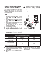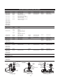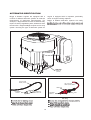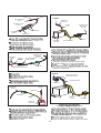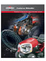
1
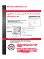
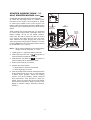
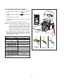
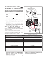
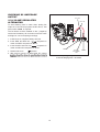
ÛÒÙ×ÒÛ ßÔÌÛÎÒßÌÑÎ ÎÛÐÔßÝÛÓÛÒÌ ÙË×ÜÛ Ì¸»Ð±©»®Ð±®¬¿´ò½±³ DZ«® •Ñ²» ͬ±°Œ ײº±®³¿¬·±² ͱ«®½» °±®¬¿´ º±® ·¬- º¿³·´§ ±º °®±¼«½¬-ô ̸»Ð±©»®Ð±®¬¿´ò½±³ò ÐÑÉÛÎ ÐÑÎÌßÔ ÚÛßÌËÎÛÍ Í»½«®»ô ±²ó¼»³¿²¼ô îì¨é ¿½½»-- ¬± ³»¿²·²¹º«´ ·²º±®³¿¬·±² ¿²¼ º«²½¬·±²- º±® ¿´´ ±º ±«® °®±¼«½¬-ò α´»ó¾¿-»¼ -»½«®·¬§ ¬¸¿¬ ©·´´ ¼§²¿³·½¿´´§ ¹»²»®¿¬» ¿² ·²¬»®º¿½» ¿²¼ ½±²¬»²¬ ײ¬»®¿½¬ ª·¿ ¬¸» ·²¬»®²»¬ º±® ¿ ª¿®·»¬§ ±º ¾«-·²»-- ¬®¿²-¿½¬·±²-ò Ø»®» ·- ¿ ¹´·³°-» ±º ¬¸» ¿ª¿·´¿¾´» º»¿¬«®»- ±² ¬¸» ¾®¿²¼- º±® ©¸·½¸ §±« °®±ª·¼» -¿´»- ¿²¼ñ±® -»®ª·½» º±®ò »²¼ °®±¼«½¬Ûó°¿®¬- ó -»®ª·½» °¿®¬- ¿²¼ñ±® ©¸±´» ¹±±¼- ´±±µó«° ¿²¼ ±®¼»®·²¹ Ì»½¸ °®»-- -»¿®½¸ λ󰱩»®·²¹ ¿²¼ ®»°´¿½»³»²¬ »²¹·²» ´±±µó«° ïôððð- ±º ¬»½¸²·½¿´ ¿²¼ -»®ª·½» ¼±½«³»²¬- Ë-» Þ®·¹¹- ú ͬ®¿¬¬±² Ù»²«·²» п®¬Þ®·¹¹- ú ͬ®¿¬¬±² »²¹·²» ©¿®®¿²¬§ ¼±»- ²±¬ ½±ª»® »²¹·²» ¼¿³¿¹» ½¿«-»¼ ¾§ ²±²ó±®·¹·²¿´ °¿®¬-ò Þ®·¹¹- ú ͬ®¿¬¬±² ®»½±³³»²¼- ¬¸» «-» ±º ¹»²«·²» Þ®·¹¹- ú ͬ®¿¬¬±² °¿®¬- º±® ©¿®®¿²¬§ ½´¿·³-ò Table of Contents Continuity Checks - Switches DC Voltage Battery Test Resistance Checks Diode Checks Ê .................................................................................................................... 2 .......................................................................................................................... 2 ..................................................................................................................................... 2 ......................................................................................................................................... 3 DC Shunt ........................................................................................................................................................ 4 How Does A Shunt Work? .............................................................................................................................. 4 Ohm's Law Formula ....................................................................................................................................... 5 DC Shunt Instructions..................................................................................................................................... 7 No-Load Starter Current Draw 12 Volt Starter Motors 300mV Starter Current Draw – 12 Volt Starter Motors íðð³Ê AC Voltage Output Check v DC Amperage Output Check ..................................................................... 8 ........................................................................... 9 ..................................................................................................................... 10 .................................................................................................................11 Checking DC Amperage Output ................................................................................................................... 12 16 & 20 Amp Regulated Alternator ............................................................................................................... 12 Starter Motor Current Draw 120 Volt Starter Motors A ............................................................................. 13 Electric Starter Kits Quick Reference ........................................................................................................... 14 ................................................................................................................................. 15 Engine/Alternator Replacement Information................................................................................................. 17 Replacing Briggs & Stratton Engines ........................................................................................................... 17 Briggs & Stratton Engine Replacing Engine Of Another Manufacturer ........................................................ 21 Performance Control™ Electronic Governor ................................................................................................ 40 AWG Wire Sizes........................................................................................................................................... 41 Metric Wire Gauges...................................................................................................................................... 41 Load Carrying Capacities ............................................................................................................................. 41 Glossary of Terms......................................................................................................................................... 44 1 CONTINUITY CHECKS - SWITCHES 1. Insert RED test lead into v meter. 2. Insert BLACK test lead into meter. 3. Rotate selector to ÐËÍØ ÞËÌÌÑÒ ÍÉ×ÌÝØ øÛÔÛÝÌÎ×Ý ÍÌßÎÌ÷ receptacle in ÝÑÓ ÎÑÌßÎÇ ÕÛÇ ÍÉ×ÌÝØ receptacle in ×ÙÒ×Ì×ÑÒ ÍÌÑÐ ÍÉ×ÌÝØ position. 4. When meter test leads are attached to switch terminals and switch is in “ON” position, a continuous tone indicates continuity. With switch in “OFF” position, no tone indicates no continuity (incomplete circuit). An incomplete circuit will be displayed as “OL”. ÌÑÙÙÔÛ ÍÉ×ÌÝØ Ý±²¬·²«·¬§ ݸ»½µ- DC VOLTAGE BATTERY TEST 1. Insert RED test lead into v meter. 2. Insert BLACK test lead into meter. 3. Rotate selector to Ê Ê receptacle in ÔÛßÜ ÝÑÓ receptacle in ÔÛßÜ position. 4. Connect RED test lead to õ (positive) terminal on battery and BLACK test lead to ó (negative) terminal. Battery voltage can be checked as shown. Þ¿¬¬»®§ °±-¬-ô ¬»®³·²¿´- ¿²¼ ®»´¿¬»¼ ¿½½»--±®·»½±²¬¿·² ´»¿¼ ¿²¼ ´»¿¼ ½±³°±«²¼-ô ½¸»³·½¿´µ²±©² ¬± ¬¸» ͬ¿¬» ±º Ý¿´·º±®²·¿ ¬± ½¿«-» ½¿²½»® ¿²¼ ¾·®¬¸ ¼»º»½¬- ±® ±¬¸»® ®»°®±¼«½¬·ª» ¸¿®³ò ÉßÍØ ØßÒÜÍ ßÚÌÛÎ ØßÒÜÔ×ÒÙò ÜÝ Ê±´¬¿¹» Þ¿¬¬»®§ Ì»-¬ RESISTANCE CHECKS 1. Insert RED test lead into v meter. 2. Insert BLACK test lead into meter. 3. Rotate selector to receptacle in ÝÑÓ receptacle in position. 4. Attach test leads to component being tested. 5. Meter will display amount of ohms resistance in component being tested. ÌÇÐ×ÝßÔ ï ÑØÓ ÎÛÍ×ÍÌÑÎ ÚÑÎ ÌÎ×óÝ×ÎÝË×Ì ßÔÌÛÎÒßÌÑΠλ-·-¬¿²½» ݸ»½µ- 2 DIODE CHECKS In the Diode Test position, the meter will display the forward voltage drop across the diode(s). If the voltage drop is less than 0.7 volt, the meter will “beep”once, as well as display the voltage drop. A continuous tone indicates continuity (shorted diode). An incomplete circuit (open diode) will be displayed as “OL”. 1. Insert RED test lead into v meter. ÌÛÍÌ ÔÛßÜ ÚÎÑÓ ÓÛÌÛÎ ÌÛÍÌ ÔÛßÜ ÚÎÑÓ ÓÛÌÛÎ receptacle in É×ÎÛ ÚÎÑÓ ÍÌßÌÑÎ ß Þ 2. Insert BLACK test lead into meter. 3. Rotate selector to ÝÑÓ receptacle in position. Ü×ÑÜÛ ÝÑÒÒÛÝÌÑÎ 4. Attach RED test lead to point “A”and BLACK test lead to point “B”. (It may be necessary to pierce wire with a pin as shown.) a. If meter “beeps”once, diode is OK. b. If meter makes a continuous tone, diode is defective (shorted). c. If meter displays “OL”, proceed to step 5. 5. Reverse test leads. a. If meter “beeps” once, diode is installed backwards. b. If meter still displays “OL”, diode is defective (open). í ß³° ÜÝ ÌÛÍÌ ÔÛßÜ ÚÎÑÓ ÓÛÌÛÎ •ÞËÓÐŒ ÑÒ ÝÑÒÒÛÝÌÑÎ ×ÒÜ×ÝßÌÛÍ Ü×ÑÜÛ Í×ÜÛ ß Þ Ü×ÑÜÛ ÌÛÍÌ ÔÛßÜ ÚÎÑÓ ÓÛÌÛÎ É×ÎÛ ÚÎÑÓ ÍÌßÌÑÎ ÝÑÒÒÛÝÌÑÎ Ü«¿´ Ý·®½«·¬ Š ݸ¿®¹·²¹ ˲·¬ ÌÛÍÌ ÔÛßÜ ÚÎÑÓ ÓÛÌÛÎ É×ÎÛ ÚÑÎ ÝØßÎÙ×ÒÙ Ý×ÎÝË×Ì ÌÛÍÌ ÔÛßÜ ÚÎÑÓ ÓÛÌÛÎ ÌÛÍÌ ÔÛßÜ ÚÎÑÓ ÓÛÌÛÎ Þ Ü×ÑÜÛ ß Ü×ÑÜÛ ÌÛÍÌ ÔÛßÜ ÚÎÑÓ ÓÛÌÛÎ ß É×ÎÛ ÚÑÎ Ô×ÙØÌ×ÒÙ Ý×ÎÝË×Ì Þ Ì®·óÝ·®½«·¬ Š ݸ¿®¹·²¹ Ý·®½«·¬ Ì®·óÝ·®½«·¬ Š Ô·¹¸¬·²¹ Ý·®½«·¬ 3 RED TEST LEAD BLACK TEST LEAD BEEP B A Yes C B Yes C D Yes D A Yes ÒÑÌÛæ for “grounds”, as follows: case, touch each terminal, A – D, with RED test lead probe. Meter should display “OL”at each terminal. If meter makes a continuous tone at any terminal, A D B C DC SHUNT Have you ever wanted one tool in your toolbox that would make your life so much easier that it would might well be the ïçíëç DC shunt. The DC shunt is a device that enables the technician to make several electrical tests with only one hook-up to the equipment. By using the DC shunt, we can test for system draw with the key switch off, system draw with the key switch on, starter peak amp and steady amp draw, and alternator charging. All of these tests can be done in about 30 seconds taking all the guess work out of the process. Electricity is one of those mysterious entities that most of us are at best, very leery of or at worst, down right frightened of. But once we have a basic understanding of electrical theory, and acknowledge that electricity has to follow strict physical properties, electrical testing becomes one of the easiest troubleshooting problems we will encounter. HOW DOES A SHUNT WORK? Several years ago we introduced the ïçíëç DC Shunt as a complement to the Fluke Digital Multi-meter. Though a very effective and useful tool, two questions usually come up: Why is a reading taken in millivolts to read amperage? Can I use the shunt with another brand of meter? The shunt works by adding a measured load (resistance) to a DC series circuit. Any load in a circuit will cause a voltage drop across that particular part of the total load. The two meter connecting posts are across part of the posts. The meter must be set to the millivolt scale in order to obtain the correct reading. This is actually a much safer approach than working with higher amperage. 4 ÚÑÎ ÞÔßÝÕ ÔÛßÜ ÚÎÑÓ ÓÛÌÛÎ ÎÛÍ×ÍÌßÒÝÛ ÍÛÝÌ×ÑÒ ÚÑÎ ÎÛÜ ÔÛßÜ ÚÎÑÓ ÓÛÌÛÎ ÝÑÒÒÛÝÌÍ ÌÑ ÒÛÙßÌ×ÊÛ ÞßÌÌÛÎÇ ÝßÞÔÛ ÝÑÒÒÛÝÌÍ ÌÑ ÒÛÙßÌ×ÊÛ ÞßÌÌÛÎÇ ÐÑÍÌ Ð®»ª·±«- ͬ§´» Ý«®®»²¬ ͬ§´» Note: Meter and battery connections to shunt are the same as the previous DC shunt as shown above. OHM'S LAW FORMULA Some background information may help to make this clearer. Ohm’ s Law states that 1 volt of electrical pressure ÛãרΠor volts equals amps multiplied by resistance. ï ª±´¬ ã ï ¿³° ¨ ï ±¸³ The DC shunt is designed to have a predetermined resistance of 0.001 ohm between the meter connection posts. When we use the shunt to check the alternator charge rate, amps is the unknown. Changing Ohm’ s Law around to determine the current gives us: ï ª±´¬ ï ¿³° ã óóóóóóóóó ï ±¸³ could be called a milliinch. Therefore, 1/1000 of an amp equals 0.001 amp or one milliamp. Also, one millivolt is 1/1000th of a volt or 0.001 volt. Applying these units of measurement for Briggs & Stratton shunt into Ohm’ s Law gives us: ï ³·´´·ª±´¬ ðòððï ª±´¬ ï ¿³° ã óóóóóóóóóóóóóóóóó ã óóóóóóóóóóóóóóóóó ï ³·´´·±¸³ ðòððï ±¸³ The above equation shows that across the posts on the Briggs & Stratton shunt, 1 milliohm equals 1 amp of 5 shunt will stay the same. We know the current will change. Since the shunt measures voltage drop, we have to be interested in the voltage or pressure in the system. The resistance value of the shunt is set so that we know there is a 1 to 1 ratio between amps and millivolts. Therefore, a reading of 2 millivolts on the meter face is equal to 2 amps of current, 3 equals 3, etc. From this discussion, it should be clear that any meter capable of reading millivolts can be used with the DC shunt. 6 DC SHUNT INSTRUCTIONS The DC shunt, part number ïçìêè readily adapts to standard mount, side mount or tab type battery terminals. The shunt must be installed on the ó (negative) terminal of the battery. For standard terminals, attach ring terminal on shunt to post terminal on battery. For tab terminal batteries, attach shunt to battery terminal using 1/4" – 20 stud and wing nut. For side terminal batteries, remove post terminal from shunt and thread into side terminal on battery. Attach battery cable to shunt using 3/8" – 16 nut from post terminal. The Digital Multimeter will withstand DC input of 10 –20 Amps for up to 30 seconds. To avoid blowing fuse in meter, use the DC shunt when checking current draw of 12 volt starter motors or DC output on 16 Amp regulated alternator. Charging output can be checked with the engine running. All connections must be clean and tight for correct amperage readings. 1. Install shunt on negative battery terminal. ÔÛßÜ ÔÛßÜ ÒÛÙßÌ×ÊÛ ÞßÌÌÛÎÇ ÌÛÎÓ×ÒßÔ 2. Insert RED test lead into v receptacle in meter and RED receptacle on shunt. 3. Insert BLACK test lead into ÝÑÓ receptacle in meter and BLACK receptacle on shunt. 4. Rotate selector switch to ßÌÌßÝØ ÒÛÙßÌ×ÊÛ ÞßÌÌÛÎÇ ÝßÞÔÛ íðð³Ê ÒÛÙßÌ×ÊÛ ÞßÌÌÛÎÇ ÌÛÎÓ×ÒßÔ ßÌÌßÝØ ÒÛÙßÌ×ÊÛ ÞßÌÌÛÎÇ ÝßÞÔÛ ÒÛÙßÌ×ÊÛ ÞßÌÌÛÎÇ ÌÛÎÓ×ÒßÔ ßÌÌßÝØ ÒÛÙßÌ×ÊÛ ÞßÌÌÛÎÇ ÝßÞÔÛ É×ÌØ íñèþóïê ÒËÌ ÒÛÙßÌ×ÊÛ ÞßÌÌÛÎÇ ÌÛÎÓ×ÒßÔ Í¬¿²¼¿®¼ Ó±«²¬ Ì¿¾ Ó±«²¬ 7 Í·¼» Ó±«²¬ position. NO-LOAD STARTER CURRENT DRAW 12 VOLT STARTER MOTORS íðð³Ê ÌÛÍÌ ÔÛßÜ ÚÎÑÓ ÓÛÌÛÎ (STARTER MOTOR REMOVED FROM ENGINE) To check the no-load amperage draw of a 12 volt starter motor that is removed from the engine, a ÌÛÍÌ ÔÛßÜ ÚÎÑÓ ÓÛÌÛÎ ÐÎÛÍÍ ÌÑ ÍÌßÎÌ the diagram for the parts necessary to make a test set-up. ÝßËÌ×ÑÒæ DO NOT clamp motor housing in a vise. Starter motors contain two ceramic magnets which can be broken or cracked if the motor housing is deformed or dented. ÒÑÌÛæ When checking starter current draw, battery voltage must not be below 11.7 volts. ÒÑÌÛ ÎÐÓ ÑÚ ÍÌßÎÌÛÎ ÓÑÌÑÎ ÌßÝØÑÓÛÌÛÎ 1. Install shunt on ó (negative) battery terminal. ïî ʱ´¬ ͬ¿®¬»® Ý«®®»²¬ Ü®¿© Š ÜÝ Í¸«²¬ 2. Insert RED test lead into v receptacle in meter and RED receptacle on shunt. 3. Insert BLACK test lead into ÝÑÓ receptacle in meter and BLACK receptacle on shunt. ÜÎ×ÔÔ ÌÉÑ ØÑÔÛÍ Š íñèþ Ü×ßò ÚÑÎ ÍÌßÎÌÛÎ ÓÑËÒÌ×ÒÙ ÞÎßÝÕÛÌ ÐßÎÌ ÒËÓÞÛÎ íçîéìç ÜÎ×ÔÔ ÌÉÑ ØÑÔÛÍ ÚÑÎ ÓÑËÒÌ×ÒÙ îóïñìþ ÞÎ×ÙÙÍ ú ÍÌÎßÌÌÑÒ ëéòî ÓÓ ÐßÎÌ ÒËÓÞÛÎ ïçîðð ÌßÝØÑÓÛÌÛÎ ýé ÜÎ×ÔÔ ÌßÐ ØÑÔÛ ÚÑÎ ïñìóîð ÒÝ ÍÝÎÛÉÍ íóïñî" èç ÓÓ ÛÈÌÎß ØÑÔÛ ÚÑÎ ÓÑËÒÌ×ÒÙ ÍÌßÎÌÛÎ ÞÎßÝÕÛÌÍ ìþ ïðî ÓÓ •ÔŒ íóïñî" èç ÓÓ ï" îëòì ÓÓ ïð" îëì ÓÓ ÓÛÌßÔ ÍÌÑÝÕ Š ïñìþ ÌØ×ÝÕ ÍÌÛÛÔ î" ëï ÓÓ ÌÛÍÌ ÞÎßÝÕÛÌ Í¬¿®¬»® Ó±¬±® ر«-·²¹ Ô»²¹¬¸ ر© ¬± Ó¿µ» ¬¸» Ì»-¬ Ó±«²¬·²¹ Þ®¿½µ»¬ ÌßÞÔÛ ï ïî ÊÑÔÌ ÍÌßÎÌÛÎ ÓÑÌÑÎ ÍÐÛÝ×Ú×ÝßÌ×ÑÒÍ ÓÑÌÑÎ ØÑËÍ×ÒÙ ÔÛÒÙÌØ Ó×Ò×ÓËÓ ÎÐÓ ÓßÈ×ÓËÓ ßÓÐÛÎßÙÛ 3" (76 mm) 6500 18 3-5/8" (92 mm) 6500 18 3-3/4" (95 mm) 6500 19 4-3/8" (111 mm) 6500 20 4-1/2" (114 mm) 6500 35 4. Rotate meter selector to íðð³Ê position. 5. Activate the starter switch: a. Note RPM on vibration tachometer. b. Note amperage on meter. being tested. 7. If the starter motor does not meet the Repair Instruction Manual, Section 7, for service and repair procedure. 6. Note starter motor housing length and refer to 8 STARTER CURRENT DRAW – 12 VOLT STARTER MOTORS íðð³Ê (STARTER MOTOR MOUNTED ON ENGINE) To check the amperage draw of a starter motor mounted on the engine, the procedure is similar to checking the starter motor off the engine. The battery cable and key switch harness installed in the equipment may be substituted for the test harness shown. ×ÙÒ×Ì×ÑÒ ÌÛÍÌÛÎ ÌÑÑÔ ÐßÎÌ ÒËÓÞÛÎ ïçíêè When making this current draw test, it is important to monitor the engine RPM, amperage draw and battery voltage. On all 12 volt starter systems, make sure the test is performed with the correct oil in engine, and belts removed from the PTO shaft. Remove the spark plug(s) and ground the spark plug wire(s) using Ignition Tester(s), Tool part number ïçíêè. Also the engine temperature should be at least 68 to 70° F (20° C). ÌÛÍÌ ÔÛßÜÍ ÚÎÑÓ ÓÛÌÛÎ ÒÛÙßÌ×ÊÛ ÞßÌÌÛÎÇ ÌÛÎÓ×ÒßÔ ÒÑÌÛæ When checking starter current draw, battery voltage must not be below 11.7 volts. ïî ʱ´¬ ͬ¿®¬»® Ý«®®»²¬ Ü®¿© Š ÜÝ Í¸«²¬ 1. Install shunt on ó (negative) battery terminal. 2. Insert RED test lead into v receptacle in meter and RED receptacle on shunt. 3. Insert BLACK test lead into ÝÑÓ receptacle in meter and BLACK receptacle on shunt. 4. Rotate meter selector to position. 5. Activate the starter switch: a. Note RPM on vibration tachometer. b. Note amperage on meter. 6. If the amperage draw exceeds 100 amps and the engine RPM is less than 350, it could indicate a starter motor problem. Check the starting system, such as the battery, cables, solenoid and connections. Then proceed to check the starter motor by performing the no-load starter motor test as indicated on page 8 or refer to the Briggs & Stratton Repair Instruction Manual, Section 7. 9 AC VOLTAGE OUTPUT CHECK v 1. Insert RED test lead into v meter. 2. Insert BLACK test lead into meter. ÜËßÔ Ý×ÎÝË×Ì receptacle in ÝÑÒÒÛÝÌÑÎ ÝÑÓ receptacle in ÎÛÜ ÝÔ×Ð ÌÑ ßÝ Í×ÜÛ ÑÚ ØßÎÒÛÍÍ øÞÔßÝÕ É×ÎÛ ÷ 3. Rotate selector to position. 4. Attach RED test clip to alternator AC output terminal(s). 5. Attach BLACK test clip to engine ground. ÒÑÌÛæ When checking AC voltage output of stator on 10-16 and 20 amp regulated or QuadCircuit alternator systems, attach one meter test clip to each output pin terminal in YELLOW connector from stator. Test clip leads may be attached to either output pin. 6. With engine running at 3600 RPM, AC output ÌÛÍÌ ÝÔ×Ð ÌÑ ß ÙÑÑÜ ÙÎÑËÒÜ ÍËÎÚßÝÛ alternator type in Table 2. ÌÛÍÌ ÝÔ×Ð ÌÑ ßÝ ÑËÌÐËÌ Ð×Ò ÌßÞÔÛ î ÝÑÒÒÛÝÌÑÎ ßÔÌÛÎÒßÌÑÎ ßÝ ÑËÌÐËÌ ßÌ íêðð ÎÐÓ AC ON LY 14 VOLTS DUAL CIRCUIT 14 VOLTS 28 VOLTS ßÌÌßÝØ ÓÛÌÛÎ ÌÛÍÌ ÝÔ×ÐÍ 40 VOLTS TRI-CIRCUIT 28 VOLTS QUAD-CIRCUIT 30 VOLTS ÝÑÒÒÛÝÌÑÎ ÏËßÜóÝ×ÎÝË× Ì ïð ßÓÐ Ý×ÎÝË×Ì ïê ßÓÐ Ý×ÎÝË×Ì 20 VOLTS ÝÑÒÒÛÝÌÑÎ ÌÛÍÌ ÝÔ×Ð ç ßÓÐ ÎÛÙËÔßÌÛÜ ÌÎ×óÝ×ÎÝË×Ì ÌÛÍÌ ÝÔ×Ð Í×ÒÙÔÛ Ý×ÎÝË× Ì ßÝ ÑÒÔÇ ßÝ Ê±´¬¿¹» Ñ«¬°«¬ ݸ»½µ 30 VOLTS 26 VOLTS magne t size. 10 DC AMPERAGE OUTPUT CHECK Í»» Ò±¬» Þ»´±© Ú±® ïñî ß³° ¿²¼ ͧ-¬»³ í ú ì ß´¬»®²¿¬±®- •ÞËÓÐŒ ÑÒ ÝÑÒÒÛÝÌÑÎ ×ÒÜ×ÝßÌÛÍ ÌØÛ ÜÝ ÑËÌÐËÌ Ð×Ò ÔÑ ÝßÌ×ÑÒ ßÝ ÑËÌÐËÌ Ð×Ò Í»» п¹» ïì º±® Í°»½·¿´ ײ-¬®«½¬·±²- ±² ݸ»½µ·²¹ ÜÝ ß³°»®¿¹» Ñ«¬°«¬ ±º ïê ¿²¼ îð ß³° λ¹«´¿¬»¼ ͧ-¬»³ 1. Insert RED test lead into meter. 2. Insert BLACK test lead into meter. 3. Rotate selector to receptacle in ÝÑÓ ÜËßÔ Ý×ÎÝË×Ì ÍÇÍÌÛÓ ÜÝ ÑËÌÐËÌ Ð×Ò receptacle in ÌÛÍÌ ÔÛßÜ ÌÑ ÜÝ ÑËÌÐËÌ Ð× Ò position. 4. Attach RED test clip to DC output terminal. 5. Attach BLACK test clip to õ (positive) battery terminal. (See note for System 3 & 4 alternators.) 6. With engine running at 3600 RPM, DC output for alternator type shown in Table 3. ÒÑÌÛæ ïñî ßÓÐ ßÒÜ ÍÇÍÌÛÓ í ú ÜÝ ßÓÐÛÎßÙÛ ÑËÌÐËÌ ÝØÛÝÕæ ì Follow DC output check procedure as described above through step 4. ÔÛßÜ ÌÑ ÐÑÍ×Ì×ÊÛ ÞßÌÌÛÎÇ ÌÛÎÓ×ÒßÔ At step 5, attach BLACK test clip to ground. At step 6, with engine running at 2800 RPM, DC output should be no less than 0.5 amp. ÜÝ ß³°»®¿¹» Ñ«¬°«¬ ݸ»½µ ÌßÞÔÛ í ßÔÌÛÎÒßÌÑÎ ÌÇÐÛ ÜÝ ÑËÌÐËÌ 1/2 AMP, SYS TEM 3 & 4 * .5 AMP DC ONLY (VANGUAR D™ ) (1.2 AMP) 1.2 AMP DC ONLY (MODEL 130000 ) (1.5 AMP) 1.5 AMP DC ONLY (3 AMPS) **2–4 AMPS DUAL CIRCUIT **2–4 AMPS *QUAD -CIRCUIT **3–8 AMPS *5 AMPS RE GULATED **3–5 AMPS *9 AMPS RE GULATED **3–9 AMPS *10 AMPS R EGULATED **3–10 AMPS *16 AMPS R EGULATED **3–16 AMPS *20 AMPS R EGULATED **3–20 AMPS Connect test leads before starting engine. Be sure connections are secure. If a test lead vibrates loose while engine is running, the regulator/ 11 ** Amperage will vary with battery voltage. If battery voltage is at its maximum, the amperage will be less than the higher value shown. CHECKING DC AMPERAGE OUTPUT ÌÛÍÌ ÔÛßÜ 16 & 20 AMP REGULATED ALTERNATOR ÌÛÍÌ ÔÛßÜ To avoid blowing fuse in meter when testing DC output of 16 and 20 amp system the DC Shunt, Tool part number ïçìêè, is required. The DC Shunt must be installed on the ó (negative) terminal of the battery. All connections must be clean and tight for correct amperage readings. 1. Install shunt on negative battery terminal. 2. Insert RED test lead into v receptacle in meter and RED receptacle on shunt. 3. Insert BLACK test lead into ÝÑÓ receptacle in meter and BLACK receptacle on shunt. 4. Rotate selector to íðð³Ê ÌÛÎÓ×ÒßÔ ÜÝ ÍØËÒÌ ÐßÎÌ ÒËÓÞÛÎ ïçìêè position. 5. With engine running at 3600 RPM, DC output ÌÛÎÓ×ÒßÔ ÜÝ ß³°»®¿¹» Ñ«¬°«¬ ݸ»½µ ïê ¿²¼ îð ß³° ͧ-¬»³ Š ÜÝ Í¸«²¬ Table 3. 12 ÝßËÌ×ÑÒæ ׺ ¿³°»®¿¹» ·- ¸·¹¸»® ¬¸¿² STARTER MOTOR CURRENT DRAW 120 VOLT STARTER MOTORS A -¬±° ¬¸» ¬»-¬ÿ ß² ¿³°»®¿¹» ®»¿¼·²¹ ¸·¹¸»® ¬¸¿² ²«³¾»® ·² ½¸¿®¬ô ·²¼·½¿¬»¿ -¸±®¬»¼ -¬¿®¬»® ³±¬±®ô ©¸·½¸ ½±«´¼ ¾» ¼¿²¹»®±«-ò Use Line Current Adapter, Tool part number ïçíëè, when checking current draw on 120 volt starter volt starter test to check the current draw and free running RPM of motor. ̸» º±´´±©·²¹ ¬»-¬ °®±½»¼«®» ³«-¬ ¾» «-»¼ ¬± ¿ª±·¼ ¿²§ ¿½½·¼»²¬¿´ -¸±½µ ¸¿¦¿®¼ ¬± ¬¸» -»®ª·½» ¬»½¸²·½·¿²ò ßÝ Ô×ÒÛ ÊÑÔÌßÙÛ ÓËÍÌ ÞÛ ÒÑ ÔÛÍÍ ÌØßÒ ïïð ÊÑÔÌÍ ÐËÍØ ÍÉ×ÌÝØ ÌÑ ßÝÌ×ÊßÌÛ ÍÌßÎÌÛÎ 1. Insert BLACK test lead from adapter, Tool part number ïçíëè, into the ÝÑÓ receptacle in meter. 2. Insert white test lead from adapter, Tool part number ïçíëè, into the receptacle in meter. 3. Plug the adapter cord (female end) into the switch box receptacle of the starter motor. 4. Plug the adapter cord (male end) into the previously tested wall outlet. 5. Rotate selector to A position. ÌßÝØÑÓÛÌÛÎ ÎÛßÜ ÎÐÓ ÑÚ ÍÌßÎÌÛÎ ÓÑÌÑÎ maximum allowable amperage draw for motor being tested. 7. Depress starter switch button. When meter reading stabilizes, (approximately 3 seconds) ïîð ʱ´¬ ßÝ Í¬¿®¬»® Ó±¬±® Ý«®®»²¬ Ü®¿© ©·¬¸ Ô·²» Ý«®®»²¬ ß¼¿°¬»® shown in Table 4. ÌßÞÔÛ ì ïîð ÊÑÔÌ ÍÌßÎÌÛÎ ÓÑÌÑÎ ÍÐÛÝ×Ú×ÝßÌ×ÑÒÍ ÍÌßÎÌÛÎ ÓÑÌÑÎ ×ÜÛÒÌ×Ú×ÝßÌ×ÑÒ ÓßÈ×ÓËÓ ßÓÐÛÎßÙÛ Ó×Ò×ÓËÓ ÎÐÓ America n Bosch SME–110–C3 SME–110–C6 SME–110–C8 3.5 7400 America n Bosch 06026–28–M030SM 3.0 7400 Mitsubi shi J28218 8 3.5 7800 2.7 6500 Briggs & Stratton 10. If the starter motor does not meet the given check RPM using vibration tachometer, Tool part number ïçîðð. Table 4. 13 Manual, Section 7. ÛÔÛÝÌÎ×Ý ÍÌßÎÌÛÎ Õ×ÌÍ ÏË×ÝÕ ÎÛÚÛÎÛÒÝÛ ÛÒÙ×ÒÛ ÓÑÜÛÔ ÍÌßÎÌÛÎ ßÍÍÛÓÞÔÇý ÍÌßÎÌÛÎ ÙÛßÎ ÑÒÔÇý ÜÎ×ÊÛ ßÍÍÇò ý øÞÛÒÜ×È÷ Í·²¹´» ݧ´·²¼»® Û²¹·²»s 190400-196499 497595 (Plastic Ring Gear) 695708 (Plastic Ring Gear) 696541 190700-195799 693054 (Alum. Ring Gear) 693059 (Alum. Ring Gear) 696540 (C Ring Type) (Roll Pin Type) 252700-252799 693551 (Steel Ring Gear) 693713 (Steel Ring Gear) 693699 (Steel Ring Gear) 253700-253799 499521 (Plastic Ring Gear/Starter Housing is Over 4" in Length) 194700-198799 499521 (Alum. Ring Gear/Starter Housing is Over 4" in Length) 195400-195799 693552 (Steel Ring Gear/Starter Housing is Over 4" in Length) 696541 (C Ring Type) 693713 (Steel Ring Gear) 696541 (C Ring Type) 696540 (Roll Pin Type) 496181 (Steel Pinion Gear) 19E400-19E499 19F400-19F499 19G400-19G499 19K400-19K499 280700-289799 28A700-28W799 Í·²¹´» ݧ´·²¼»® ײ¬»µ‡ Û²¹·²»120100-15D100 793667 120 volt (60Hz Starter Assembly) 699786 230 volt (50Hz Starter Assembly) 795909 120 volt (60HZ Starter Assembly) 792157 230 volt (50Hz Starter Assembly) 310700-310799 497595 (Plastic Ring Gear) 695708 (Plastic Ring Gear) 311700-311799 497595 (Alum. Ring Gear) 693059 (Alum. Ring Gear) 312700-312799 693551 (Steel Ring Gear) 693699 (Steel Ring Gear) 695708 20A100-21P200 Ñ°°±-»¼ Ì©·² ݧ´·²¼»® Û²¹·²»400400-422499 497596 (3 5/8" Housing) 400700-422799 498148 (4 3/8" Housing) 42A700-42E799 406700-461799 ÊóÌ©·² Ê¿²¹«¿®¼‡ Û²¹·²»303400-303499 499521 354400-354499 691564 695708 (Steel Pinion Gear) N/A (Steel Pinion Gear) 696541 (C Ring Type) 496881 (Steel Pinion Gear) 350700-350799 380400-381499 380700-381799 303700-303799 499521 304400-304499 691564 (Steel Pinion Gear) 695708 N/A 696541 (C Ring Type) 496881 (Steel Pinion Gear) 691564 (Steel Pinion Gear) 695708 696541 (C Ring Type) 695708 696541 (Steel Pinion Gear) 350400-350499 351400-351499 351700-351799 381400-381499 381700-381799 ÊóÌ©·² ײ¬»µ‡ Û²¹·²»405700-405799 499521 406700-406799 407700-407799 445700-445799 ÎÛÌß×Ò×ÒÙ Î×ÒÙ ÝÔËÌÝØ ÜÎ×ÊÛ ÍÌßÎÌÛÎ ÜÎ×ÊÛ ßÍÍÛÓÞÔÇ ÜËÍÌ ÝÑÊÛÎ ÎÛÌß×ÒÛÎ ÎÑÔÔ Ð×ÒóÍÔÑÌ ËÐ ÍÐÎ×ÒÙ ÉßÍØÛÎ ÎÛÌß×Ò×ÒÙ Î×ÒÙ ËÐÐÛÎ ÎÛÌß×ÒÛÎ Ð×Ò×ÑÒ ÙÛßÎ ÍÐÎ×ÒÙ ÎÛÌËÎÒ ÍÐÎ×ÒÙ ÉßÍØÛÎ ÞÛÊÛÔÛÜ ÛÜÙÛ ËÐ ÔÑÉÛÎ ÎÛÌß×ÒÛÎ ÝÔËÌÝØ ÍÌßÎÌÛÎ ÓÑÌÑÎ ÍÌßÎÌÛÎ ÝÔËÌÝØ Ð×Ò×ÑÒ ÙÛßÎ ØÛÔ×È Ýóη²¹ ̧°» α´´ з² ̧°» 14 ͬ»»´ η²¹ Ù»¿® ALTERNATOR IDENTIFICATION Briggs & Stratton engines are equipped with a number of different alternator systems to meet the requirements of equipment manufacturers. For example, a large lawn tractor with accessories may require a 16 amp regulated system, whereas a snow thrower with a single headlight requires an AC Only system. Knowing the type of alternator system an engine is equipped with is important, particularly when an engine is being replaced. Briggs & Stratton alternator systems are easily the connector. ÍÌßÌÑÎ ÑËÌÐËÌ É×ÎÛøÍ÷ ßÒÜ ÝÑÒÒÛÝÌÑÎ øÌÇÐ×ÝßÔ÷ ÑÒÛ ÔÛßÜ ÚÎÑÓ ÛÒÙ×ÒÛ øÍÌßÌÑÎ÷ ÑÒÛ ÔÛßÜ ÚÎÑÓ ÛÒÙ×ÒÛ øÍÌßÌÑÎ÷ ÝÑÒÒÛÝÌÑÎ ÌÑ ÛÏË×ÐÓÛÒÌ ØßÎÒÛÍÍ ÝÑÒÒÛÝÌÑÎ ÑËÌÐËÌ ÔÛßÜ Ü×ÑÜÛ ÌÑ ÛÏË×ÐÓÛÒÌ ØßÎÒÛÍÍ ßÝ Ñ²´§ ÜÝ Ñ²´§ 15 ÔÛßÜ ßÝ ÑËÌÐËÌ ÔÛßÜ ÜÝ ÑËÌÐËÌ ÌÑ ÛÏË×ÐÓÛÒÌ ØßÎÒÛÍÍ ÔÛßÜÍ ÚÎÑÓ ÛÒÙ×ÒÛ øÍÌßÌÑÎ÷ ÝÑÒÒÛÝÌÑÎ ÑËÌÐËÌ ÔÛßÜ ÜÝ ÝØßÎÙ×ÒÙ Ý×ÎÝË×Ì ÎÛÜ ÔÛßÜ ÌÑ ÛÏË×ÐÓÛÒÌ ØßÎÒÛÍÍ ÑÒÛ ÎÛÜ ÔÛßÜ ÌÉÑ ÞÔßÝÕ ÔÛßÜÍ ÚÎÑÓ ÛÒÙ×ÒÛ øÍÌßÌÑÎ÷ ÝÑÒÒÛÝÌÑÎ ÔÛßÜ ßÝ ÚÑÎ Ô×ÙØÌÍ ßÝ Ñ²´§ ÝÑÒÒÛÝÌÑÎ (ONE RED lead from stator). ÎÛÙËÔßÌÑÎñ ÎÛÝÌ×Ú×ÛÎ ÌÉÑ ÇÛÔÔÑÉ ÔÛßÜÍ (ONE BLACK lead from stator). ïð ÑÎ ïê ß³° λ¹«´¿¬»¼ ÌÑ ÛÏË×ÐÓÛÒÌ ØßÎÒÛÍÍ alternator magnet size. ÑÒÛ ÞÔßÝÕ ÔÛßÜ ÚÎÑÓ ÛÒÙ×ÒÛ øÍÌßÌÑÎ÷ ë ßÓÐ ÜÝ øó÷ ÌÑ Ô×ÙØÌÍ ÉØ×ÌÛ ÔÛßÜ ÌÉÑ Ü×ÑÜÛÍ ÛÒÝßÍÛÜ ×Ò É×ÎÛ ØßÎÒÛ ÍÍ YELLOW connector with two pin terminals. YELLOW ÝÑÒÒÛÝÌÑÎ ÔÛßÜ ë ßÓÐÍ ÜÝøõ÷ ÌÑ ÞßÌÌÛÎÇ ßÒÜ ÝÔËÌÝØ Ý×ÎÝË×Ì connector output lead. Ì®·óÝ·®½«·¬ ÌÑ ÛÏË×ÐÓÛÒÌ ØßÎÒÛÍÍ ÎÛÜ É×ÎÛ ßÒÜ Îß×ÍÛÜ Î×Þ ×ÒÜ×ÝßÌÛÍ ÜÝ ÑËÌÐËÌ GREEN connector. ÝØßÎÙ×ÒÙ ×ÒÜ×ÝßÌÑÎ ÝÑÒÒÛÝÌÑÎ ÌÑ ÛÏË×ÐÓÛÒÌ ØßÎÒÛÍÍ ÔÛßÜ ÚÎÑÓ ÛÒÙ×ÒÛ øÍÌßÌÑÎ÷ ÝÑÒÒÛÝÌÑÎ ÝÑÒÒÛÝÌÑÎ ÇÛÔÔÑÉ É×ÎÛ ÌÉÑ ÇÛÔÔÑÉ ÔÛßÜÍ ÝÑÒÒÛÝÌÑÎ ÎÛÙËÔßÌÑÎñ ÎÛÝÌ×Ú×ÛÎ Ë-»¼ É·¬¸ ݸ¿®¹» ײ¼·½¿¬±® Ý·®½«·¬ ë ±® ç ß³° λ¹«´¿¬»¼ equipment manufacturer. BLUE charge indicator wire to white connector. GREEN connector. 16 ENGINE/ALTERNATOR REPLACEMENT INFORMATION With the exception of the AC Only alternator, all of the alternator systems referred to in this book have a battery as part of the electrical system. There are specialized applications that use an alternator without a battery. An example would be certain generators or welders that use alternator to function, the alternator output must be very evenly matched to the equipment requirements. When replacing an engine in these applications, the alternator must be the same as the original. REPLACING BRIGGS & STRATTON ENGINES regulated system. We can integrate the two systems by making an adapter harness from readily available parts. Generally an unregulated DC system (DC Only, Dual Circuit) should not be used to replace a regulated system because alternator output may not be because the equipment requirements are usually much less on an unregulated DC system, a regulated system may be used as a replacement. being over charged. ÒÑÌÛæ The AC Only, DC Only, Dual Circuit, TriCircuit as well as the 5 and 10 amp alternator magnets. The 9 and 16 amp When replacing an older Briggs & Stratton engine on a piece of equipment with a newer Briggs & Stratton engine, sometimes the newer engine has an alternator system different from the alternator system on the original engine. This means that the output connector on the replacement engine is not compatible with the original wiring harness on the piece of equipment. For example, the original engine may have been equipped with a Dual Circuit system and the replacement engine is equipped with a for magnet sizes. *Small Magnet 7/8" x 11/16" (22mm x 18mm) *Large Magnet 1-1/16" x 15/16" (27mm x 24mm) ßÔÌÛÎÒßÌÑÎ ÓßÙÒÛÌÍ *V Twin Alternator Magnet S ize: Small 7 /8" x 21/32" (22 mm x 17 mm ) Large 7 /8" x 29/32" (22 mm x 23 mm ) 17 ̸» º±´´±©·²¹ ¿®» ¿´¬»®²¿¬±® ®»°´¿½»³»²¬ ½±³¾·²¿¬·±²- ©¸·½¸ ®»¯«·®» ¿² ¿¼¿°¬»® ¸¿®²»--ò ß´´ ±º ¬¸» ²»½»--¿®§ ½±³°±²»²¬- ¿®» -¸±©²ò 1. Original engine equipped with AC Only alternator. Replacement engine equipped with Dual Circuit alternator. Modify íçèêêï harness supplied with replacement engine by removing RED DC wire. Then, splice íçíëíé connector into white AC wire and connect to equipment harness. ÛÏË×ÐÓÛÒÌ ØßÎÒÛÍÍ ßÝ É×ÎÛ ÜËßÔ Ý×ÎÝË×Ì ÝÑÒÒÛÝÌÑÎ øÚÎÑÓ ÛÒÙ×ÒÛ÷ íçííêî ØßÎÒÛÍÍ ßÝ ÜÝ ÍÐÔ×ÝÛ Î×Þ íçíëíé ÝÑÒÒÛÝÌÑÎ Î×Þ 2. Original engine equipped with DC Only alternator. Replacement engine equipped with Dual Circuit alternator. Modify íçèêêï harness supplied with replacement engine by removing white AC wire. Then, splice íçíëíé connector into RED DC wire and connect to equipment harness. ÜËßÔ Ý×ÎÝË×Ì ÝÑÒÒÛÝÌÑÎ øÚÎÑÓ ÛÒÙ×ÒÛ÷ íçííêî ØßÎÒÛÍÍ ÛÏË×ÐÓÛÒÌ ØßÎÒÛÍÍ ÜÝ É×ÎÛ ßÝ ÜÝ Î×Þ ÍÐÔ×ÝÛ Î×Þ 18 íçíëíé ÝÑÒÒÛÝÌÑÎ 3. Original engine equipped with Dual Circuit alternator. Replacement engine equipped with 5, 9, 10 or 16 amp regulated system. Modify êçîíðê harness supplied with replacement engine by splicing in íçççïê connector assembly. Connect to equipment harness. íçççïê ÝÑÒÒÛÝÌÑÎ ßÍÍÛÓÞÔÇ ÑËÌÐËÌ ÝÑÒÒÛÝÌÑÎ ÚÎÑÓ ÎÛÙËÔ ßÌÑÎ ÛÏË×ÐÓÛÒÌ ØßÎÒÛÍÍ ÍÐÔ×ÝÛ êçîíðê ØßÎÒÛÍÍ Î×Þ Î×Þ 4. Original engine equipped with Tri-Circuit alternator. Replacement engine equipped with 5, 9, 10 or 16 amp regulated system. Modify êçîíðê harness supplied with replacement engine by splicing into charging circuit wire and lighting circuit wire in equipment harness. ÒÑÌÛæ THE DIODES MUST BE REMOVED FROM THE EQUIPMENT HARNESS. ÍÐÔ×ÝÛ ÑËÌÐËÌ ÝÑÒÒÛÝÌÑÎ ÚÎÑÓ ÎÛÙËÔ ßÌÑÎ Ô×ÙØÌ×ÒÙ Ý×ÎÝË×Ì É ×ÎÛ ÛÏË×ÐÓÛÒÌ ØßÎÒÛÍÍ êçîíðê ØßÎÒÛÍÍ ÝØßÎÙ×ÒÙ Ý× ÎÝË×Ì É×ÎÛ Ü·±¼»- Ó«-¬ Þ» λ³±ª»¼ Ú®±³ Û¯«·°³»²¬ Ø¿®²»-- 19 5. Original engine equipped with Dual Circuit alternator. Replacement engine equipped Tri-Circuit alternator. Discard êçïçëë diode harness supplied with new engine. Install éçìíêð harness and modify by splicing in íçççïê connector assembly. Connect to equipment harness. íçççïê ÝÑÒÒÛÝÌÑÎ ßÍÍÛÓÞÔÇ ÑËÌÐËÌ ÝÑÒÒÛÝÌÑÎ ÚÎÑÓ ßÔÌÛÎÒßÌÑÎ ÍÐÔ×ÝÛ íçíìîî ØßÎÒÛÍÍ Î×Þ Î×Þ ÛÏË×ÐÓÛÒÌ ØßÎÒÛÍÍ éçìíêð ÎÛÙËÔßÌÑÎñÎÛÝÌ×Ú×ÛÎ 6. Original engine equipped with 5 amp regulated system. Replacement engine equipped with Tri-Circuit alternator. Discard êçïçëë diode harness supplied with new engine. Transfer ìçïëìê engine. Connect to equipment harness. 7. Original engine equipped with DC Only alternator. Replacement engine equipped with 5, 9, 10 or 16 amp regulated system. Direct Replacement. Connect to equipment harness. 8. Original engine equipped with 5 amp regulated system. Replacement engine equipped with 9, 10 or 16 amp regulated system. Direct Replacement. Connect to equipment harness. 9. Original engine equipped with 9 amp regulated system. Replacement engine equipped with 10 or 16 amp regulated system. Direct Replacement. Connect to equipment harness. 10. Original engine equipped with 10 amp regulated system. Replacement engine equipped with 9 or 16 amp regulated system. Direct Replacement. Connect to equipment harness. 20 êçîíðê BRIGGS & STRATTON ENGINE REPLACING ENGINE OF ANOTHER MANUFACTURER When replacing the engine of another manufacturer with a Briggs & Stratton engine, the equipment requirements must be known so that the replacement alternator system has the same output as the original system provided. Often the equipment wiring harness is not compatible with the Briggs & Stratton alternator output harness. To create a compatible system it may be necessary to modify the equipment wiring harness. To do this, a wiring diagram for the equipment is essential. The original keyswitch may also create a problem. Even though the keyswitch harness connectors appear to be identical, there are internal differences to keyswitches. Therefore it is necessary to have a diagram of the keyswitch showing the terminal positions and their functions. For example, see the 5 terminal switch diagrams in Figure 1 and Figure 2. The keyswitch in Figure 1 is compatible with all Briggs & Stratton alternators. Note in Figure 2, that when the “brand X”keyswitch is in the START position there is no battery voltage available to the #2 switch terminal. Consequently, if the replacement Briggs & Stratton engine was equipped with a carburetor solenoid, it would not function. This is why it is important to have a diagram of the keyswitch when replacing engines, or replace the keyswitch with one that is compatible with all Briggs & Stratton alternator systems. ÒÑÌÛæ The 5 terminal Briggs & Stratton keyswitch, part number ìçððêê, shown in Fig. 1 has been replaced by a 6 terminal keyswitch, part number êçîíïè. The additional terminal provides a direct connection for the charging lead at the keyswitch. ÞÎ×ÙÙÍ ú ÍÌÎßÌÌÑÒ ÍÉ×ÌÝØ ÌÛÎÓ×ÒßÔ ÐÑÍ×Ì×ÑÒÍ ÌÛÎÓ×ÒßÔ ÒÑò ÞÎßÒÜ È ÍÉ×ÌÝØ ÌÛÎÓ×ÒßÔ ÐÑÍ×Ì×ÑÒÍ ÚËÒÝÌ×ÑÒ ÌÛÎÓ×ÒßÔ ÚËÒÝÌ×ÑÒ ÒÑò 1-G Ground (U sed only with insu lated pan el) 1-A Access ory 2-L To Car buretor S olenoid 2-M To Stop Switch Terminal On Engine (Ground) 3-M To Stop Switch Terminal On Engine 3-R To Reg ulator (Ch arging) 4-S To Soleno id (Tab termin al) 4-S To Soleno id (Tab termin al) 5-B To Batter y (Battery terminal on s olenoid) 5-B To Batter y (Battery terminal on s olenoid) Ô Ó Ô 3 Ó 2 2 3 1 Ù 5 4Í 1 Ù Þ ÑÚÚ 5 Þ ÎËÒ Ô 2 Ó 3 4 Í 1 Ù 5 Þ Ó Î î Ó Î í î í ï ë ìÍ 4Í ï ìÍ ë ß Þ ß ÑÚÚ Þ ÎËÒ Ó Î î í ï ë ìÍ ß Þ ÍÌßÎÌ ÍÌßÎÌ Ú·¹«®» ï Ú·¹«®» î It is not possible to show all of the wiring diagrams or keyswitch combinations that are used by equipment manufacturers. However, the following wiring diagrams for the most popular Briggs & Stratton engines may be used as a guide when replacing an engine. The wiring diagrams show the type of keyswitch that is compatible with the alternator system shown. 21 ÍÌÑÐ ÍÉ×ÌÝØ ÌÛÎÓ×ÒßÔ ßÒÌ×óßÚÌÛÎÚ×ÎÛ ÍÑÔÛÒÑ×Ü ßÔÌÛÎÒßÌÑÎ Ü×ÑÜÛ ÕÛÇ ÍÉ×ÌÝØ ßÝ ÑËÌÐËÌ É×ÎÛ î í ï ë ì ÜÝ ÑËÌÐËÌ É×ÎÛ õ ßÓÓÛÌÛÎ ÍÑÔÛÒÑ×Ü ÌßÞ ÌÛÎÓ×ÒßÔ ØÛßÜÔ×ÙØÌÍ ØÛßÜÔ×ÙØÌ ÍÉ×ÌÝØ ÍÌßÎÌÛÎ ÌÛÎÓ×ÒßÔ ÞßÌÌÛÎÇ ÌÛÎÓ×ÒßÔ ÍÑÔÛÒÑ×Ü õ ó ÍÌßÎÌÛÎ ÓÑÌÑÎ ïî ÊÑÔÌ ÞßÌÌÛÎÇ Ì§°·½¿´ Ü«¿´ Ý·®½«·¬ ß´¬»®²¿¬±® É·®·²¹ Ü·¿¹®¿³ Ñ®·¹·²¿´ ë б´» Í©·¬½¸ Í«°»®½»¼»¼ ¬± ê б´» Í©·¬½¸ô Þ®·¹¹- ú ͬ®¿¬¬±² ﮬ Ò«³¾»® êçîíïè ÕÛÇ ÍÉ×ÌÝØ ÌÛÍÌ ÌÛÎÓ×ÒßÔ ÒÑò ÚËÒÝÌ×ÑÒ ÝÑÒÌ×ÒË×ÌÇ 1 Ground ( Used onl y with ins ulated pa nel) 1. OFF *1 + 3 2 To Carbu retor Sol enoid 2. RUN 2+5 3 To Stop S witch Terminal On E ngine 2+4+5 4 To Solen oid (Tab termi nal) *Terminal 1 Grou nded Inte rnally To Key Switch C ase 5 To Batter y (Battery terminal on solen oid) ÍÉ×ÌÝØ ÐÑÍ×Ì×ÑÒ 3. START 22 ÍÌÑÐ ÍÉ×ÌÝØ ÌÛÎÓ×ÒßÔ ßÒÌ×óßÚÌÛÎÚ×ÎÛ ÍÑÔÛÒÑ×Ü ßÔÌÛÎÒßÌÑÎ Ü×ÑÜÛ ÕÛÇ ÍÉ×ÌÝØ ßÝ ÑËÌÐËÌ É×ÎÛ ÜÝ ÑËÌÐËÌ É×ÎÛ î í ï ê ë ì ßÓÓÛÌÛÎ õ ßÓÓÛÌÛÎ øÑÐÌ×ÑÒßÔ÷ ÍÑÔÛÒÑ×Ü ÌßÞ ÌÛÎÓ×ÒßÔ õ ØÛßÜÔ×ÙØÌÍ ØÛßÜÔ×ÙØÌ ÍÉ×ÌÝØ ÍÌßÎÌÛÎ ÌÛÎÓ×ÒßÔ ÞßÌÌÛÎÇ ÌÛÎÓ×ÒßÔ ÍÑÔÛÒÑ×Ü ó õ ÍÌßÎÌÛÎ ÓÑÌÑÎ ïî ÊÑÔÌ ÞßÌÌÛÎÇ Ì§°·½¿´ Ü«¿´ Ý·®½«·¬ ß´¬»®²¿¬±® É·®·²¹ Ü·¿¹®¿³ With ammet er shown in option al position , note th at connec ted to the alternato r side. ÕÛÇ ÍÉ×ÌÝØ ÌÛÍÌ and õ symbo ls are rev ersed. The õ symbo l must alw ays be ÌÛÎÓ×ÒßÔ ÒÑò ÚËÒÝÌ×ÑÒ ÝÑÒÌ×ÒË×ÌÇ 1 Ground (U sed only with insulated panel) 1. OFF *1 + 3 + 6 2 To Carbur etor Solen oid 2. RUN 2+5+6 3 To Stop S witch Terminal On En gine 2+4+5 4 To Soleno id (Tab te rminal) *Terminal 1 Grou nded Inte rnally To Key Switch C ase 5 To Battery (Battery terminal on so lenoid) 6 To Alterna tor (DC Outpu t) ÍÉ×ÌÝØ ÐÑÍ×Ì×ÑÒ 3. START 23 24 ÞßÌÌÛÎÇ ÉØ×ÌÛ ÝÑÒÒÛÝÌÑÎ ÞÔßÝÕ ßÝ ÑËÌÐËÌ Ì§°·½¿´ Ü«¿´ Ý·®½«·¬ ͧ-¬»³ ÜÝ ÑËÌÐËÌ ÎÛÜ Ü×ÑÜÛ ÍÌßÌÑÎ ÍÌßÎÌ ÍÉ×ÌÝØ 2 3 4 1 5 ÍÌßÎÌÛÎ ÍÑÔÛÒÑ×Ü 6 ÍÌßÎÌÛÎ ßÓÓÛÌÛÎ Ô×ÙØÌ ÍÉ×ÌÝØ ÍÌÑÐ ÍÉ×ÌÝØ ÌÛÎÓ×ÒßÔ ßÒÌ×óßÚÌÛÎÚ×ÎÛ ÍÑÔÛÒÑ×Ü ßÔÌÛÎÒßÌÑÎ ÕÛÇ ÍÉ×ÌÝØ ßÝ ÑËÌÐËÌ É×ÎÛ î í ï ë ì ÜÝ ÑËÌÐËÌ É×ÎÛ ÎÛÙËÔßÌÑÎñ ÎÛÝÌ×Ú×ÛÎ õ ßÓÓÛÌÛÎ ÍÑÔÛÒÑ×Ü ÌßÞ ÌÛÎÓ×ÒßÔ ÞßÌÌÛÎÇ ÌÛÎÓ×ÒßÔ ÍÌßÎÌÛÎ ÌÛÎÓ×ÒßÔ ØÛßÜÔ×ÙØÌÍ ÍÑÔÛÒÑ×Ü ØÛßÜÔ×ÙØÌ ÍÉ×ÌÝØ õ ó ÍÌßÎÌÛÎ ÓÑÌÑÎ ïî ÊÑÔÌ ÞßÌÌÛÎÇ Ì§°·½¿´ ïê ß³° λ¹«´¿¬»¼ ß´¬»®²¿¬±® É·®·²¹ Ü·¿¹®¿³ ÕÛÇ ÍÉ×ÌÝØ ÌÛÍÌ ÌÛÎÓ×ÒßÔ ÒÑò ÚËÒÝÌ×ÑÒ ÝÑÒÌ×ÒË×ÌÇ 1 Ground ( Used onl y with ins ulated pa nel) 1. OFF *1 + 3 2 To Carbu retor Sol enoid 2. RUN 2+5 3 To Stop S witch Terminal On E ngine 2+4+5 4 To Solen oid (Tab termi nal) *Terminal 1 Grou nded Inte rnally To Key Switch C ase 5 To Batter y (Battery terminal on solen oid) ÍÉ×ÌÝØ ÐÑÍ×Ì×ÑÒ 3. START 25 ÍÌÑÐ ÍÉ×ÌÝØ ÌÛÎÓ×ÒßÔ ßÒÌ×óßÚÌÛÎÚ×ÎÛ ÍÑÔÛÒÑ×Ü ßÔÌÛÎÒßÌÑÎ ÕÛÇ ÍÉ×ÌÝØ î ßÝ ÑËÌÐËÌ É×ÎÛ í ì ï ê ÜÝ ÑËÌÐËÌ É×ÎÛ ë ßÓÓÛÌÛÎ õ ÎÛÙËÔßÌÑÎñ ÎÛÝÌ×Ú×ÛÎ ßÓÓÛÌÛÎ øÑÐÌ×ÑÒßÔ÷ õ ÍÑÔÛÒÑ×Ü ÌßÞ ÌÛÎÓ×ÒßÔ ÞßÌÌÛÎÇ ÌÛÎÓ×ÒßÔ ÍÌßÎÌÛÎ ÌÛÎÓ×ÒßÔ ØÛßÜÔ×ÙØÌÍ ÍÑÔÛÒÑ×Ü ØÛßÜÔ×ÙØÌ ÍÉ×ÌÝØ ó õ ÍÌßÎÌÛÎ ÓÑÌÑÎ ïî ÊÑÔÌ ÞßÌÌÛÎÇ Ì§°·½¿´ ïê ß³° λ¹«´¿¬»¼ ß´¬»®²¿¬±® É·®·²¹ Ü·¿¹®¿³ With ammet er shown in option al position , note th at connec ted to the alternato r side. ÕÛÇ ÍÉ×ÌÝØ ÌÛÍÌ and õ symbo ls are rev ersed. The õ symbo l must alw ays be ÌÛÎÓ×ÒßÔ ÒÑò ÚËÒÝÌ×ÑÒ ÝÑÒÌ×ÒË×ÌÇ 1 Ground (U sed only with insulated panel) 1. OFF *1 + 3 + 6 2 To Carbur etor Solen oid 2. RUN 2+5+6 3 To Stop S witch Terminal On En gine 2+4+5 4 To Soleno id (Tab te rminal) *Terminal 1 Grou nded Inte rnally To Key Switch C ase 5 To Battery (Battery terminal on so lenoid) 6 To Alterna tor (DC Outpu t) ÍÉ×ÌÝØ ÐÑÍ×Ì×ÑÒ 3. START 26 ßÔÌÛÎÒßÌÑÎ ÍÌÑÐ ÍÉ×ÌÝØ ÌÛÎÓ×ÒßÔ ßÒÌ×óßÚÌÛÎÚ×ÎÛ ÍÑÔÛÒÑ×Ü ÝØßÎÙÛ ×ÒÜ×ÝßÌÑÎ Ô×ÙØÌ ßÝ ÑËÌÐËÌ É×ÎÛ î í ï ë ì ê ÞÔËÛ É×ÎÛ ßÓÓÛÌÛÎ ÎÛÙËÔßÌÑÎñ ÎÛÝÌ×Ú×ÛÎ õ ÎÛÜ É×ÎÛ ÜÝ ÑËÌÐËÌ Îß×ÍÛÜ Î×Þ ßÓÓÛÌÛÎ øÑÐÌ×ÑÒßÔ÷ ÍÑÔÛÒÑ×Ü ÌßÞ ÌÛÎÓ×ÒßÔ õ ÞßÌÌÛÎÇ ÌÛÎÓ×ÒßÔ ÍÌßÎÌÛÎ ÌÛÎÓ×ÒßÔ ØÛßÜÔ×ÙØÌÍ ÍÑÔÛÒÑ×Ü ØÛßÜÔ×ÙØÌ ÍÉ×ÌÝØ ó õ ÍÌßÎÌÛÎ ÓÑÌÑÎ ïî ÊÑÔÌ ÞßÌÌÛÎÇ Ì§°·½¿´ ïê ß³° λ¹«´¿¬»¼ ß´¬»®²¿¬±® É·®·²¹ Ü·¿¹®¿³ É·¬¸ ݸ¿®¹» ײ¼·½¿¬±® Ô·¹¸¬ With ammet er shown in option al position , note th at connec ted to the alternato r side. ÕÛÇ ÍÉ×ÌÝØ ÌÛÍÌ ÍÉ×ÌÝØ ÐÑÍ×Ì×ÑÒ and õ symbo ls are rev ersed. The õ symbo l must alw ays be ÌÛÎÓ×ÒßÔ ÒÑò ÚËÒÝÌ×ÑÒ ÝÑÒÌ×ÒË×ÌÇ 1 Ground (U sed only with insulated panel) 1. OFF *1 + 3 + 6 2 To Carbur etor Solen oid 2. RUN 2+5+6 3 To Stop S witch Terminal On En gine 2+4+5 4 To Soleno id (Tab te rminal) *Terminal 1 Grou nded Inte rnally To Key Switch C ase 5 To Battery (Battery terminal on so lenoid) 6 To Alterna tor (DC Outpu t) 3. START 27 28 ÍÌßÎÌÛÎ ßÔÌÛÎÒßÌÑÎ ÙÎÑËÒÜ É×ÎÛ ÌÛ ÎÓ×ÒßÔ ÞßÌÌÛÎÇ Ô×ÙØÌ ÍÉ×ÌÝØ ÍÛßÌ ÍÉ×ÌÝØ ßÓÓÛÌÛΠ̧°·½¿´ ïðñïê ß³° ͧ-¬»³ ÛÔÛÝÌÎ×Ý ÝÔËÌÝØ ÍÌßÎÌÛÎ ÎÛÔßÇ - + ß Þ ß Þ Ü Ý Û Ý ß Ý 2 3 4 1 5 Þ Ü 6 ÝÔËÌÝØ ÞÎßÕÛ ÍÉ×ÌÝØ ÌÎ×óÝ×ÎÝË×Ì ÍÌßÌÑÎ ÍÌÑÐ ÍÉ×ÌÝØ ÌÛÎÓ×ÒßÔ ßÒÌ×óßÚÌÛÎÚ×ÎÛ ÍÑÔÛÒÑ×Ü ßÔÌÛÎÒßÌÑÎ ÕÛÇ ÍÉ×ÌÝØ ßÝ ÑËÌÐËÌ É×ÎÛ ÜÝ ÑËÌÐËÌ É×ÎÛ î í ï ê ë ì ßÓÓÛÌÛÎ ÎÛÙËÔßÌÑÎñ ÎÛÝÌ×Ú×ÛÎ õ ßÓÓÛÌÛÎ øÑÐÌ×ÑÒßÔ÷ ÍÑÔÛÒÑ×Ü ÌßÞ ÌÛÎÓ×ÒßÔ õ ÍÌßÎÌÛÎ ÌÛÎÓ×ÒßÔ ÞßÌÌÛÎÇ ÌÛÎÓ×ÒßÔ ØÛßÜÔ×ÙØÌÍ ÍÑÔÛÒÑ×Ü ØÛßÜÔ×ÙØÌ ÍÉ×ÌÝØ õ ó ÍÌßÎÌÛÎ ÓÑÌÑÎ ïî ÊÑÔÌ ÞßÌÌÛÎÇ Ì§°·½¿´ ëñç ß³° λ¹«´¿¬»¼ ß´¬»®²¿¬±® É·®·²¹ Ü·¿¹®¿³ É·¬¸ ݸ¿®¹» ײ¼·½¿¬±® Ô·¹¸¬ With ammet er shown in option al position , note th at connec ted to the alternato r side. ÕÛÇ ÍÉ×ÌÝØ ÌÛÍÌ and õ symbo ls are rev ersed. The õ symbo l must alw ays be ÌÛÎÓ×ÒßÔ ÒÑò ÚËÒÝÌ×ÑÒ ÝÑÒÌ×ÒË×ÌÇ 1 Ground (U sed only with insulated panel) 1. OFF *1 + 3 + 6 2 To Carbur etor Solen oid 2. RUN 2+5+6 3 To Stop S witch Terminal On En gine 2+4+5 4 To Soleno id (Tab te rminal) *Terminal 1 Grou nded Inte rnally To Key Switch C ase 5 To Battery (Battery terminal on so lenoid) 6 To Alterna tor (DC Outpu t) ÍÉ×ÌÝØ ÐÑÍ×Ì×ÑÒ 3. START 29 ÌÎ×óÝ×ÎÝË×Ì ÍÌßÌÑÎ ÍÌÑÐ ÍÉ×ÌÝØ ÌÛÎÓ×ÒßÔ ßÒÌ×óßÚÌÛÎÚ×ÎÛ ÍÑÔÛÒÑ×Ü ßÝ ÑËÌÐËÌ É×ÎÛ ßÔÌÛÎÒßÌÑÎ ÕÛÇ ÍÉ×ÌÝØ ó ÜÝ ÑËÌÐËÌ É×ÎÛ î í ï ë ì õ ÜÝ ÑËÌÐËÌ É×ÎÛ ØÛßÜÔ×ÙØÌ ÍÉ×ÌÝØ ê ßÓÓÛÌÛÎ õ ßÓÓÛÌÛÎ øÑÐÌ×ÑÒßÔ÷ ØÛßÜÔ×ÙØÌÍ ÞßÌÌÛÎÇ ÌÛÎÓ×ÒßÔ ÍÑÔÛÒÑ×Ü ÌßÞ ÌÛÎÓ×ÒßÔ õ ÍÌßÎÌÛÎ ÌÛÎÓ×ÒßÔ ÝÔËÌÝØ ÍÉ×ÌÝØ ÍÑÔÛÒÑ×Ü ÛÔÛÝÌÎ×Ý ÝÔËÌÝØ ó õ ÍÌßÎÌÛÎ ÓÑÌÑÎ ïî ÊÑÔÌ ÞßÌÌÛÎÇ Ì§°·½¿´ Ì®·óÝ·®½«·¬ ß´¬»®²¿¬±® É·®·²¹ Ü·¿¹®¿³ With ammet er shown in option al position , note th at connec ted to the alternato r side. ÕÛÇ ÍÉ×ÌÝØ ÌÛÍÌ ÍÉ×ÌÝØ ÐÑÍ×Ì×ÑÒ and õ symbo ls are rev ersed. The õ symbo l must alw ays be ÌÛÎÓ×ÒßÔ ÒÑò ÚËÒÝÌ×ÑÒ ÝÑÒÌ×ÒË×ÌÇ 1 Ground (U sed only with insulated panel) 1. OFF *1 + 3 + 6 2 To Carbur etor Solen oid 2. RUN 2+5+6 3 To Stop S witch Terminal On En gine 2+4+5 4 To Soleno id (Tab te rminal) *Terminal 1 Grou nded Inte rnally To Key Switch C ase 5 To Battery (Battery terminal on so lenoid) 6 To Alterna tor (DC Outpu t) 3. START 30 31 Þ Ý Ô×ÙØÌ ÍÉ×ÌÝØ ß Ü Û ÐÌÑ ÍÉ×ÌÝØ ï ÍÌßÌÑÎ îëÉ ÎÛÍ×ÍÌÑÎ ÞßÌÌÛÎÇ ÙÎÛÛÒ ÝÑÒÒÛÝÌÑÎ ×ÒÌÛÎÔÑÝÕ ÍÉ×ÌÝØ ÍÌßÎÌÛÎ ÍÑÔÛÒÑ×Ü ÝÔËÌÝØ î í ï ë ÍÌßÎÌ ÍÉ×ÌÝØ ì ÍÌßÎÌÛÎ 32 õ ßÓÓÛÌÛÎ *Terminal 1 Grou nded Inte rnally To Key Switch C ase 2+4+5 2+5 2. RUN 3. START *1 + 3 ÝÑÒÌ×ÒË×ÌÇ 1. OFF ÍÉ×ÌÝØ ÐÑÍ×Ì×ÑÒ ÕÛÇ ÍÉ×ÌÝØ ÌÛÍÌ To prevent this, route wire B to #2 terminal on key-switch. ÝÔËÌÝØ ÍÉ×ÌÝØ ÑÒ ÑÚÚ õ ÜÝ ÑËÌÐËÌ É×ÎÛ ßÝ ÑËÌÐËÌ É×ÎÛ Note: If clutch switch is in ON position with keyswitch OFF, battery will discharge through clutch. ØÛßÜÔ×ÙØÌÍ ØÛßÜÔ×ÙØÌ ÍÉ×ÌÝØ ó ÜÝ ÑËÌÐËÌ É×ÎÛ ßÔÌÛÎÒßÌÑÎ ÌÎ×óÝ×ÎÝË×Ì ÍÌßÌÑÎ ÛÔÛÝÌÎ×Ý ÝÔËÌÝØ ÎÛÍ×ÍÌÑÎ Þ ß õ ÍÛÛ ÒÑÌÛ ßÒÌ×óßÚÌÛÎÚ×ÎÛ ÍÑÔÛÒÑ×Ü ë î ïî ÊÑÔÌ ÞßÌÌÛÎÇ ÍÑÔÛÒÑ×Ü ÞßÌÌÛÎÇ ÌÛÎÓ×ÒßÔ ï í ÕÛÇ ÍÉ×ÌÝØ ì ÍÌßÎÌÛÎ ÌÛÎÓ×ÒßÔ ÍÑÔÛÒÑ×Ü ÌßÞ ÌÛÎÓ×ÒßÔ ÍÌÑÐ ÍÉ×ÌÝØ ÌÛÎÓ×ÒßÔ ÍÌßÎÌÛÎ ÓÑÌÑÎ 33 *Terminal 1 Grou nded Inte rnally To Key Switch C ase 2+4+5 2+5 2. RUN 3. START *1 + 3 õ ÝÔËÌÝØ ÜÐÜÌ ÍÉ×ÌÝØ ÑÒ ÑÚÚ õ ÜÝ ÑËÌÐËÌ É×ÎÛ ßÝ ÑËÌÐËÌ É×ÎÛ ßÓÓÛÌÛÎ ÝÑÒÌ×ÒË×ÌÇ 1. OFF ÍÉ×ÌÝØ ÐÑÍ×Ì×ÑÒ ÕÛÇ ÍÉ×ÌÝØ ÌÛÍÌ ØÛßÜÔ×ÙØÌÍ ØÛßÜÔ×ÙØÌ ÍÉ×ÌÝØ ó ÜÝ ÑËÌÐËÌ É×ÎÛ ßÔÌÛÎÒßÌÑÎ ÌÎ×óÝ×ÎÝË×Ì ÍÌßÌÑÎ ÛÔÛÝÌÎ×Ý ÝÔËÌÝØ ÎÛÍ×ÍÌÑÎ ÞßÌÌÛÎÇ ÌÛÎÓ×ÒßÔ õ ßÒÌ×óßÚÌÛÎÚ×ÎÛ ÍÑÔÛÒÑ×Ü ê ë í ïî ÊÑÔÌ ÞßÌÌÛÎÇ ÍÑÔÛÒÑ×Ü ï î ÕÛÇ ÍÉ×ÌÝØ ì ÍÌßÎÌÛÎ ÌÛÎÓ×ÒßÔ ÍÌßÎÌÛÎ ÓÑÌÑÎ ÍÑÔÛÒÑ×Ü ÌßÞ ÌÛÎÓ×ÒßÔ ÍÌÑÐ ÍÉ×ÌÝØ ÌÛÎÓ×ÒßÔ 34 ÍÌßÎÌ ÍÉ×ÌÝØ ë ï í î ì ÞßÌÌÛÎÇ ó õ Þ Ý ß ÍÌßÌÑÎ ÍÛßÌ ÍÉ×ÌÝØ Þ ß Þ ÝÔËÌÝØñ ÞÎßÕÛ ÍÉ×ÌÝØ ÚËÍÛ Ì§°·½¿´ ݱ³°´»¨ Ì®·óÝ·®½«·¬ ͧ-¬»³ ÙÎÛÛÒ ÝÑÒÒÛÝÌÑÎ ÐÌÑ ÍÉ×ÌÝØ ß Ü Û ßÓÓÛÌÛÎ Ý Ü Ô×ÙØÌ ÍÉ×ÌÝØ ß ÐÌÑ ÝÔËÌÝØ Þ ÍÌßÎÌÛÎ ÎÛÔßÇ ÍÌßÎÌÛÎ ÊóÌÉ×Ò É×ÎÛ ØßÎÒÛÍÍ ÜÛÍÝÎ×ÐÌ×ÑÒ Óìðñìì É×ÌØ ýî Í×ÜÛ ÎÛÙËÔßÌÑÎô ÉñÑ ÛÚÓ Óìç É×ÌØ ýï Í×ÜÛ ÎÛÙËÔßÌÑÎô ÉñÑ ÛÚÓ Óìðñììñìç É×ÌØ ýï Í×ÜÛ ÎÛÙËÔßÌÑÎô É×ÌØ ÛÚÓ 2 pin, s tandard 499235 499235 796393 Used w ith (RED, regulator out) (Jumper Wire) 499813 796452 796452 6 pin, s tandard 694215 795359 796374 6 pin w ith oil pre ssure swi tch 694216 795360 796375 6 pin w ith hour m eter or o il minder 696505 795361 796376 Used w ith 69421 5, 69421 6 and 696505 . RED wi re from re gulator to 2 pin 694214 693876 795703 795703 Bracke t, Hold Do wn (wire) na 227680 227680 Tie wrap fo r regulat or wires (inside blower) na yes yes ßÍÍÑÝ× ßÌÛÜ ÐßÎÌÍ Shield/N ut Assem bly #1 s ide 35 Ú 36 í î Û ç ïë Ü ÍÛÛ ÜÛÌß×Ô Õ ß ÜÛÌß×Ô •ÕŒ ÕÛÇ ê Ü×ÑÜÛÍ ïì ÝÎ×ÓÐÛÜ ÝÑÒÒÛÝÌ×ÑÒ ïë ÍØÎ×ÒÕ ÌËÞ×ÒÙ ê Ð×Ò ÝÑÒÒÛ ÝÌÑÎ ÜÛÌß×Ô Õ ïì ÖËÓÐ ÛÎ É×ÎÛ ÞÛÌ ÉÛÛÒ ïúì ê ì þÎÑËÌ Ûþ ÌÑ ÌÛÎÓ ×ÒßÔ ØÑÔÛ Ò±ù- ßÍ ÍØ ÑÉ Òò Î×Þ Û ÛßÝØ Ü×ÑÜÛ ßÍÍÛÓÞÔÇ ÓËÍÌ ÞÛ ×Ò Ü×Ê×ÜËßÔÔÇ ÉÎßÐÐÛ Ü ×Ò ÍØ Î×ÒÕ ÌËÞ×ÒÙ ò ßÒ ß ÜÜ×Ì ×ÑÒßÔ ÍØÎ×ÒÕ ÉÎßÐ ÓËÍÌ ßÔÍÑ ÞÛ ßÍÍÛÓÞÔÛÜ ÑÊ ÛÎ ÞÑÌØ Ü×Ñ ÜÛ ßÍÍ ÛÓÞÔ×ÛÍò ïì ÍÑÝÕÛÌÍ ÓËÍÌ Þ Û ÐËÍØÛ Ü ×ÒÌÑ ØÑËÍ ×ÒÙ ËÒÌ×Ô ÌßÒÙÍ ÍÒßÐ ÑÐÛÒ ÑÊÛÎ ÐÔßÍÌ ×Ý ÌÑ ×ÒÍË ÎÛ ÌØßÌ ÍÑ ÝÕÛÌÍ ÝßÒÒ ÑÌ ÞßÝÕ ÑËÌ øì ÐÔßÝ ÛÍ÷ ì ì É×ÎÛ ×ÜÛÒÌ×Ú×ÝßÌ×ÑÒ ÎÛÚÛÎÛÒÝÛ ÌÛÎÓ×ÒßÔ ÛÒÙ×ÒÛ ÌÛÎÓ×ÒßÌ×ÑÒ ÐÑ×ÒÌ ß ÝÇÔ×ÒÜÛÎ ýï ÝÑ×Ô Þ ÝÇÔ×ÒÜÛÎ ýî ÝÑ×Ô Ý ÝßÎÞ ÍÑÔÛÒÑ×Ü Ü ÙÎÑËÒÜ Û ÐÑÉÛÎ ÍËÐÐÔÇ ÌÑ ÎÛÙËÔßÌÑÎ Ú ÛÚÓ ×ÙÒ×Ì×ÑÒ ÐËÔÍÛ Ý Þ ÝËÎÎÛÒÌ ÚÔÑÉ ÝÇÔò î ÝÇÔò ï TYPICAL 6-PIN CONNECTOR ê ë ÌØÛÎÓ×ÍÌÑÎ øÍ×ÙÒßÔ÷ ÌØÛÎÓ×ÍÌÑÎ øÙÒÜ÷ ï Í×ÙÒßÔ îóÉßÇ ÝÑÒÒÛÝÌÑÎ Í×ÙÒßÔ óóó ïî ÊÑÔÌ ÐÑÉÛÎ øÙÒÜ÷ ïî ÊÑÔÌ ÐÑÉÛÎ øõ÷ óóó óóó ïî ÊÑÔÌ ÐÑÉÛÎ øÙÒÜ÷ ïî ÊÑÔÌ ÐÑÉÛÎ øõ÷ óóó î ÌÛÎÓ×ÒßÔ ý ÌÛÎÓ×ÒßÔ ý ï î í ì ë ê é è èóÉßÇ ÝÑÒÒÛÝÌÑÎ 37 ÍÌßÌÑÎ ÇÛÔÔÑÉ ÎÛÜ ÎÛÜ ÞÔßÝÕ ë ú ç ß ÓÐ Ý×ÎÝË×Ì Ñ ÐÌ×ÑÒ ÝßÎÞ ÍÑÔÛÒÑ ×Ü í ÐÑÉÛÎ ÍËÐÐÔÇ Ú ÎÑÓ ÎÛÙËßÔÌÑÎ ÑÐÛÒ ÑÐ ÛÒ ì ë ê ÎÛÜ ó ó ÎÛÜ ÙÎßÇ ÞÔß ÝÕ ÎÛÜ É×Î Û ÝÑÔÑÎ ê Ð×Ò ÝÑÒÒÛÝÌÑÎ øÛÒÙ×Ò Û Í×ÜÛ÷ ÎÛÜ í ì ë ê î ï ì ÌÛÎÓ ×ÒßÔ ý ÞÔßÝÕ ÙÎÑËÒÜ øÑÒ ÝÇÔ×Ò ÜÛÎ ÍØ×ÛÔ Ü÷ ïê ßÓÐ Ý×ÎÝË×Ì Ñ ÐÌ×ÑÒ ÐÑÉÛ Î ÍËÐÐÔÇ ÚÎ ÑÓ Î ÛÙËÔßÌÑÎ ÝÇÔ×Ò ÜÛÎ ýï ú ýî ßÎÓßÌËÎÛ î ÙÎßÇ ÞÔßÝÕ ÙÎßÇ ÛÒÙ×Ò Û ÌÛÎÓ×ÒßÌ×Ñ Ò ÐÑ× ÒÌ ê Ð× Ò ÝÑÒÒÛ ÝÌÑÎ ÇÛÔÔÑÉ ê ï ÌÛÎÓ ×ÒßÔ ÌØÛÎÓ ×ÍÌÛÎ ÙÎßÇ ÛÚÓ ÝÑÒÌÎÑÔ ÓÑÜËÔÛ ï ë î í ê ÞÔßÝÕ ÙÎßÇ ÍÌÛÐÐÛÎ Ó ÑÌÑÎ ßÍÍÛÓÞÔÇ ÍÌÛ ÐÐÛÎ Ó ÑÌÑÎ É ×ÎÛ Þ ×ÙÒ×Ì×Ñ Ò É×Î Û ÐÎ×Ó ßÎÇ ÍÌÛ ÐÐÛÎ Ó ÑÌÑÎ É ×ÎÛ Ü ÍÌÛ ÐÐÛÎ Ó ÑÌÑÎ É ×ÎÛ Ý ÍÌÛ ÐÐÛÎ Ó ÑÌÑÎ É ×ÎÛ Û øïî ÊÑÔÌ øõ÷ ×Ò ÐËÌ ÍÌÛ ÐÐÛÎ Ó ÑÌÑÎ É ×ÎÛ ß èóÉßÇ ÝÑÒ ÒÛÝÌÑÎ Í×ÙÒßÔ 6-PIN WIRE HARNESS WITH EFM é Ü×ÑÜÛ Ü×ÑÜÛ ÝÇÔ×ÒÜÛÎ ýï ßÎÓßÌËÎÛ ÝÇÔ×ÒÜÛÎ ýî ßÎÓßÌËÎÛ ÛÚÓ ÐËÔÍÛ Í×ÙÒ ßÔ ÞÔßÝÕ ÝßÎÞ ÍÑÔÛÒÑ×Ü ÝßÎÞ ÓßÒ×ÚÑÔÜ ßÍÍÛÓÞÔÇ WIRE CONNECTORS ÊóÌÉ×Ò ê Ð×Ò ÝÑÒÒÛÝÌÑÎ ÛÒÙ×ÒÛ ÝÑÒÒÛÝÌ×ÑÒ ßÐÐÔ×ÝßÌ×ÑÒ ÝÑÒÒÛÝÌ×ÑÒ ßÓÐ Ð ×Ò ØÑËÍ×Ò Ù øÚÛÓßÔÛ óÝßÐ÷ ßÓÐ ÍÑÝÕ ÛÌ ØÑË Í×ÒÙ øÓßÔÛóÐ ÔËÙ÷ Î×Þ ×Í ßÌ ØÑÔ Û ýï ÌÑ Ô×ÙØÌ ÍÉ×ÌÝØ ØÑÔÛ ýì þ Ô×ÙØÌ ÍÉ ×ÌÝØþ ÝÑÔÑÎæ ÑÎßÒ ÙÛ ØÑÔÛ ýï þß ÔÌ ÛÎÒßÌÑÎþ ÝÑÔÑÎæ ÎÛÜ ØÑÔÛ ýë þ Ñ×Ô ÍÉ× ÌÝØþ ÝÑÔÑÎæ Ù ÎÛÛÒ ØÑÔÛ ýî þ ÓßÙÒÛÌÑ þ ÝÑÔÑÎæ ÞÔßÝÕ þßþ ÌÛÎÓ×Ò ßÔ ÌÑ Ñ×Ô Ô×Ù ØÌ ØÑÔÛ ýê þ ÑÐÛÒþ ØÑÔÛ ýí þÚËÛÔ ÍÑÔ ÛÒÑ×Üþ ÝÑÔÑÎæ ÙÎÛÇ ÕÛÇÍÉ×ÌÝØ þÓþ ÌÛÎÓ×ÒßÔ ÕÛÇÍÉ×ÌÝØ þÔþ ÌÛÎÓ×Ò ßÔ ÊóÌÉ×Ò É×ÌØ ÜËßÔ î Ð×Ò ÝÑÒÒÛÝÌÑÎÍ ÛÒÙ×ÒÛ ÝÑÒÒÛÝÌ×ÑÒ ßÐÐÔ×ÝßÌ×ÑÒ ÝÑÒÒÛÝÌ×ÑÒ ßÓÐ Ð ×Ò ØÑËÍ×Ò Ù øÚÛÓßÔÛ óÝßÐ÷ ßÓÐ ÍÑÝÕ ÛÌ ØÑË Í×ÒÙ øÓßÔÛóÐ ÔËÙ÷ ÌÑ Ô×ÙØÌ ÍÉ×ÌÝØ ØÑÔÛ ýï þ í ßÓÐ ß ÔÌÛÎÒßÌÑ Î ßÝþ ÝÑÔÑÎæ ÎÛÜ ØÑÔÛ ýî þ í ßÓÐ ß ÔÌÛÎÒßÌÑ Î ßÝþ ÝÑÔÑÎæ ÎÛÜ ÕÛÇÍÉ×ÌÝØ þßþ ÌÛÎÓ ×ÒßÔ ÛÒÙ×ÒÛ ÝÑÒÒÛÝÌ×ÑÒ ßÐÐÔ×ÝßÌ×ÑÒ ÝÑÒÒÛÝÌ×ÑÒ ßÓÐ ÍÑÝÕ ÛÌ ØÑË Í×ÒÙ øÓßÔÛóÐ ÔËÙ÷ ßÓÐ Ð ×Ò ØÑËÍ×Ò Ù øÚÛÓßÔÛ óÝßÐ÷ ØÑÔÛ ýï þ ÓßÙÒÛÌÑ þ ÝÑÔÑÎæ ÞÔßÝÕ ÕÛÇÍÉ×ÌÝØ þÓþ ÌÛÎÓ×ÒßÔ ÕÛÇÍÉ×ÌÝØ þÔþ ÌÛÎÓ×Ò ßÔ ØÑÔÛ ýî þ ÚËÛÔ Í ÑÔÛÒÑ×Ü þ ÝÑÔÑÎæ ÙÎÛÇ ÊóÌÉ×Ò É×ÌØ î Ð×Ò ÝÑÒÒÛÝÌÑÎ ßÒÜ ï Ð×Ò ÝÑÒÒÛÝÌÑÎ ÛÒÙ×ÒÛ ÝÑÒÒÛÝÌ×ÑÒ ßÐÐÔ×ÝßÌ×ÑÒ ÝÑÒÒÛÝÌ×ÑÒ ßÓÐ ÍÑÝÕ ÛÌ ØÑË Í×ÒÙ øÓßÔÛóÐ ÔËÙ÷ ßÓÐ Ð ×Ò ØÑËÍ×Ò Ù øÚÛÓßÔÛ óÝßÐ÷ þßÔÌÛÎÒ ßÌÑÎþ ÝÑÔÑÎæ Î ÛÜ ÕÛÇÍÉ×ÌÝØ þßþ ÌÛÎÓ ×ÒßÔ ÛÒÙ×ÒÛ ÝÑÒÒÛÝÌ×ÑÒ ßÐÐÔ×ÝßÌ×ÑÒ ÝÑÒÒÛÝÌ×ÑÒ ßÓÐ ÍÑÝÕ ÛÌ ØÑË Í×ÒÙ øÓßÔÛóÐ ÔËÙ÷ ßÓÐ Ð ×Ò ØÑËÍ×Ò Ù øÚÛÓßÔÛ óÝßÐ÷ ØÑÔÛ ýï þ ÓßÙÒÛÌÑ þ ÝÑÔÑÎæ ÞÔßÝÕ ÕÛÇÍÉ×ÌÝØ þÓþ ÌÛÎÓ×ÒßÔ ØÑÔÛ ýî þ ÚËÛÔ Í ÑÔÛÒÑ×Ü þ ÝÑÔÑÎæ ÙÎÛÇ ÕÛÇÍÉ×ÌÝØ þÔþ ÌÛÎÓ×Ò ßÔ 38 39 ÑÐÛÒ ÍÔÑÌ ÌÛÎÓ×ÒßÔ ÛÒÜ Ñ×Ô ÐÎÛÍÍËÎÛ øÙÎÛÛÒ÷ ×ÙÒ×Ì×ÑÒ Õ×ÔÔ øÞÔßÝÕ÷ ÙÎÑËÒÜ øÞÎÑÉÒ÷ Ê×ÛÉ ÚÎÑÓ ÌÛÎÓ×ÒßÔ ÛÒÜ ÚËÛÔ ÝËÌóÑÚÚ øÙÎßÇ÷ ÑÐÛÒ ÍÔÑÌ ÍÌßÎÌÛÎ ÍÑÔÛÒÑ×Ü ÌßÞ øÇÛÔÔÑÉ ÷ ÊÑÔÌßÙÛ ÎÛÙËÔßÌÑÎ øÎÛÜ÷ Ñ×Ô ÐÎÛÍÍËÎÛ øÙÎÛÛÒ÷ ÝËÍÌÑÓÛÎ ÝÑÒÒÛÝÌ×ÑÒ ÍÌßÎÌÛÎ ÍÑÔÛÒÑ×Ü ÞßÌÌÛÎÇ õ øÑÎßÒÙÛ÷ É×ÎÛ ÛÒÜ Þ±¬¬±³ Ê·»© η¹¸¬ Í·¼» Ê·»© ̱° Ê·»© Ô»º¬ Í·¼» Ê·»© TYPICAL 8-PIN CONNECTOR É×ÎÛ ÛÒÜ ïí ÌÑ Ú×Ì ×ÒÜßÕ ÕÛÇ ÍÉ×ÌÝØ ÚÑÎ òðíî ÌßÞ ÌØ×ÝÕÒÛÍÍ Ê×ÛÉ ÚÎÑÓ ÌÛÎÓ×ÒßÔ ÛÒÜ ÌÛÎÓ×ÒßÔ ÛÒÜ PERFORMANCE CONTROL™ ELECTRONIC GOVERNOR Some Vanguard™ V-Twin engines are equipped with the Performance Control™ electronic governor control system for generator or welder applications. The electronic governor provides more responsive governing than a mechanical governor system. Engines equipped with the Performance Control™ electronic governor control system have no mechanical governor components. The Performance Control™ electronic governor control system cannot The Performance Control™ electronic governor control system consists of an electronic control module, wiring and stop switch harness and a throttle actuator. The control module is equipped with an idle down circuit for applications requiring that feature. By cutting the yellow wire loop, the control module may be converted to 50 cycle – 3000 RPM generator applications. The engine must be turned off when cutting Yellow Cycle loop, then start the engine for the system to reset the engines RPM for 50Hz cycle. ÝßÎÞËÎÛÌÑÎ ÍÑÔÛÒÑ×Ü ÉØ×ÌÛ ×ÜÔÛ ÜÑÉÒ ÜÛÊ×ÝÛ ÞÔËÛ ëð ÝÇÝÔÛ Š íððð ÎÐÓ ÔÑÑÐ ÓÑÜËÔÛ ÍÌÑÐ ÍÉ×ÌÝØ ÌÛÎÓ×ÒßÔ ÙÎÛÛÒ ßÝÌËßÌÑÎ ÎÛÜ ÇÛÔÔÑÉ ßÔÌÛÎÒßÌÑÎ ÕÛÇ ÍÉ×ÌÝØ ßÝ ÑËÌÐËÌ É×ÎÛÍ ÜÝ ÑËÌÐËÌ É×ÎÛ î í ï ê ë ÙÎÛÇ ÞÔßÝÕ ì ÍÌÑÐ ÍÉ×ÌÝØ ØßÎÒÛÍ Í Ü×ÑÜÛ Ü×ÑÜÛ ÎÛÙËÔßÌÑÎñ ÎÛÝÌ×Ú×ÛÎ ÍÑÔÛÒÑ×Ü ÌßÞ ÌÛÎÓ×ÒßÔ ÞßÌÌÛÎÇ ÌÛÎÓ×ÒßÔ ÍÌßÎÌÛÎ ÌÛÎÓ×ÒßÔ ×ÙÒ×Ì×ÑÒ ÝÑ×ÔÍ ÍÑÔÛÒÑ×Ü ó õ ÍÌßÎÌÛÎ ÓÑÌÑÎ ïî ÊÑÔÌ ÞßÌÌÛÎÇ Ð»®º±®³¿²½» ݱ²¬®±´‡ Û´»½¬®±²·½ Ù±ª»®²±® É·®·²¹ Ü·¿¹®¿³ 40 AWG Wire Sizes (see table on the next page) AWG: In the American Wire Gauge (AWG), diameters can be calculated by applying the formula D(AWG)=.005·92((36-AWG)/39) inch. For the 00, 000, 0000 etc. gauges you use -1, -2, -3, which makes more sense mathematically than “double nought.”This means that in American wire gage every 6 gauge decrease gives a doubling of the wire diameter, and every 3 gauge decrease doubles the wire cross sectional area. Similar to dB in signal and power levels. An approximate form of this formula contributed by Mario Rodriguez is D = .460 * (57/64)(awg +3) or D = .460 * (0.890625)(awg +3). Metric Wire Gauges (see table on the next page) Metric Gauge: In the Metric Gauge scale, the gauge is 10 times the diameter in millimeters, so a 50 gauge metric wire would be 5 mm in diameter. Note that in AWG the diameter goes up as the gauge goes down, but for metric gauges it is the opposite. Probably because of this confusion, most of the time metric sized wire is Load Carr ying Capacities (see table on the next page) The following chart is a guideline of ampacity or copper wire current carrying capacity following the Handbook of Electronic Tables and Formulas for American Wire Gauge. As you might guess, the rated ampacities are just a rule of thumb. In careful engineering the voltage drop, insulation temperature limit, thickness, thermal conductivity, and air convection and temperature should all be taken into account. The Maximum Amps for Power Transmission uses the 700 circular mils per amp rule, which is very conservative. The Maximum Amps for Chassis Wiring is also a conservative rating, but is meant for wiring in air, and not in a bundle. For short lengths of wire, such as is used in battery packs you should trade off the resistance and load with size, 41 ßÉÙ ¹¿«¹» ݱ²¼«½¬±® Ü·¿³»¬»® ײ½¸»- ݱ²¼«½¬±® Ü·¿³»¬»® ³³ Ѹ³- °»® ïðð𠺬ò Ѹ³- °»® µ³ 0000 000 00 0 1 2 3 4 5 6 7 8 9 10 11 12 13 14 15 16 17 18 19 20 21 22 23 24 25 26 27 28 29 30 31 32 Metric 2.0 33 Metric 1.8 34 Metric 1.6 35 Metric 1.4 36 Metric 1.25 37 Metric 1.12 38 Metric 1 39 40 0.46 0.4096 0.3648 0.3249 0.2893 0.2576 0.2294 0.2043 0.1819 0.162 0.1443 0.1285 0.1144 0.1019 0.0907 0.0808 0.072 0.0641 0.0571 0.0508 0.0453 0.0403 0.0359 0.032 0.0285 0.0254 0.0226 0.0201 0.0179 0.0159 0.0142 0.0126 0.0113 0.01 0.0089 0.008 0.00787 0.0071 0.00709 0.0063 0.0063 0.0056 .00551 0.005 .00492 0.0045 .00441 0.004 .00394 0.0035 0.0031 11.684 10.40384 9.26592 8.25246 7.34822 6.54304 5.82676 5.18922 4.62026 4.1148 3.66522 3.2639 2.90576 2.58826 2.30378 2.05232 1.8288 1.62814 1.45034 1.29032 1.15062 1.02362 0.91186 0.8128 0.7239 0.64516 0.57404 0.51054 0.45466 0.40386 0.36068 0.32004 0.28702 0.254 0.22606 0.2032 0.200 0.18034 0.180 0.16002 0.16002 0.14224 .140 0.127 0.125 0.1143 0.112 0.1016 0.1000 0.0889 0.07874 0.049 0.0618 0.0779 0.0983 0.1239 0.1563 0.197 0.2485 0.3133 0.3951 0.4982 0.6282 0.7921 0.9989 1.26 1.588 2.003 2.525 3.184 4.016 5.064 6.385 8.051 10.15 12.8 16.14 20.36 25.67 32.37 40.81 51.47 64.9 81.83 103.2 130.1 164.1 169.39 206.9 207.5 260.9 260.9 329 339 414.8 428.2 523.1 533.8 659.6 670.2 831.8 1049 0.16072 0.202704 0.255512 0.322424 0.406392 0.512664 0.64616 0.81508 1.027624 1.295928 1.634096 2.060496 2.598088 3.276392 4.1328 5.20864 6.56984 8.282 10.44352 13.17248 16.60992 20.9428 26.40728 33.292 41.984 52.9392 66.7808 84.1976 106.1736 133.8568 168.8216 212.872 268.4024 338.496 426.728 538.248 555.61 678.632 680.55 855.752 855.752 1079.12 1114 1360 1404 1715 1750 2163 2198 2728 3440 42 Ó¿¨·³«³ ¿³°- º±® ½¸¿--·©·®·²¹ 380 328 283 245 211 181 158 135 118 101 89 73 64 55 47 41 35 32 28 22 19 16 14 11 9 7 4.7 3.5 2.7 2.2 1.7 1.4 1.2 0.86 0.7 0.53 0.51 0.43 0.43 0.33 0.33 0.27 0.26 0.21 0.20 0.17 0.163 0.13 0.126 0.11 0.09 Ó¿¨·³«³ ¿³°- º±® °±©»® ¬®¿²-³·--·±² 302 239 190 150 119 94 75 60 47 37 30 24 19 15 12 9.3 7.4 5.9 4.7 3.7 2.9 2.3 1.8 1.5 1.2 0.92 0.729 0.577 0.457 0.361 0.288 0.226 0.182 0.142 0.113 0.091 0.088 0.072 0.072 0.056 0.056 0.044 0.043 0.035 0.034 0.0289 0.0277 0.0228 0.0225 0.0175 0.0137 Ó¿¨·³«³ º®»¯«»²½§ º±® ïððû -µ·² ¼»°¬¸ º±® -±´·¼ ½±²¼«½¬±® ½±°°»® 125 Hz 160 Hz 200 Hz 250 Hz 325 Hz 410 Hz 500 Hz 650 Hz 810 Hz 1100 Hz 1300 Hz 1650 Hz 2050 Hz 2600 Hz 3200 Hz 4150 Hz 5300 Hz 6700 Hz 8250 Hz 11 kHz 13 kHz 17 kHz 21 kHz 27 kHz 33 kHz 42 kHz 53 kHz 68 kHz 85 kHz 107 kHz 130 kHz 170 kHz 210 kHz 270 kHz 340 kHz 430 kHz 440 kHz 540 kHz 540 kHz 690 kHz 690 kHz 870 kHz 900 kHz 1100 kHz 1150 kHz 1350 kHz 1400 kHz 1750 kHz 1750 kHz 2250 kHz 2900 kHz 43 Red to V Regulated two output pins with heat sink Regulated two output pin Regulated one output pin Tri Circuit 28 volts AC Output From Regulator From Stator From Regulator From Stator Wiring & diode layout varies Red to 10 amp Red to V Red to V Red to V Red to V Red to V Red to V Red to V Red to V Volts AC Red to 10 amp DC only 2-4 amps DC From Stator Amps DC Red to V AC only 14 volts AC Dual Circuit 2-4 amps DC 14 volts AC Amps DC Red to 10 amp DC only 1.5 amp DC íðð³Ê Volts AC íðð³Ê Volts AC íðð³Ê Volts AC íðð³Ê Volts AC Volts AC Amps DC Amps DC Red to 10 amp DC only 1.2 amp DC Amps DC Red to 10 amp Ì»-¬»® Í»¬¬·²¹- SYSTEM 3 & 4 also quantum 120000 1/2 amp DC ß´¬»®²¿¬±® ú ݱ²²»½¬±® Shunt on Negative Terminal Yellow Wire Shunt on Negative Terminal Either Pin Shunt on Negative Terminal Shunt on Negative Terminal Black Wire Red Wire Earth Earth Earth 3,600rpm 14 volts AC minimum 3,600rpm 2 to 4 amps DC 3,600rpm 2 to 4 amps DC 3,600rpm 14 volts AC minimum 3,600rpm 1.2 amps DC minimum 3,600rpm 1.0 amps DC minimum 2,800rpm 0.5 amps DC minimum Í°»»¼ ú λ¿¼·²¹- 3,600rpm 20 volts AC minimum for 10 & 13 amp 30 volts AC minimum for 16 amp Shunt on 3,600rpm Negative Test with regulator fully wired. Output up to 20 Terminal amps according to battery state 3,600rpm 26 volt AC minimum Shunt on 3,600rpm Negative Test with regulator fully wired. Output up to Terminal 10/13/16 amps according to battery state Other Pin Shunt on 3,600rpm Negative Test with regulator fully wired. Output up to 5 or 9 Terminal amps according to battery state 3,600rpm 28 volts AC minimum for 5 amp 40 volts AC minimum for 9 amp 3,600rpm Shunt on up to 5 amps for battery Negative Refer to service & repair instructions for Terminal additional information Shunt on 3,600rpm Negative 28 volts AC minimum Terminal Other Yellow Wire Ì»-¬»® Ô»¿¼- GLOSSARY OF TERMS In this day of lightning fast communications and an ever increasing level of sophistication in our day to day activities, the spoken word has become one of the most important tools in our toolboxes. “Word Power”is the natural extension of your thought processes. Without a high caliber vocabulary, communication with our peers and/or our customers can be severely hampered. Customers will measure us more than we might imagine, when we are unable to express our knowledge and expertise accurately and concisely. Exercising the vocabulary is every bit as important as learning the latest new service procedure. A ßÝ -·²» ©¿ª»æ A symmetrical wave form that contains 360 degrees. ßÝ ª±´¬¿¹» ¬»-¬æ A test that uses a volt meter to indicate the voltage potential of the alternator stator. ¿´¬»®²¿¬·²¹ ½«®®»²¬ øßÝ÷æ reverses direction at regular intervals. ¿´¬»®²¿¬±®æ A charging system device that produces AC voltage and amperage. A device that uses four interconnected diodes to change one cycle of AC current into two DC pulses. ¾®«-¸»-æ Carbon components, in contact with the commutator, that carry battery current to operate the starter motor. C ½¿°¿½·¬±®æ An electrical component that stores voltage. ¿³°»®¿¹»æ The strength or intensity of an electric current, measured in amperes (AMPS). ½¸¿®¹·²¹ -§-¬»³æ A system that replenishes the electrical power drawn from the battery during starting and accessory operation. ¿³°»®»-æ The measurement of the number of ½·®½«·¬æ A complete path that controls the rate time. applied. ¿®³¿¬«®»æ A rotating part of a DC motor that consists of wire wound around an armature shaft. ½·®½«·¬ ¾®»¿µ»®ô º«-» ø¿«¬±³¿¬·½ -©·¬½¸÷æ A switch ¿¬±³æ A small unit of a material that consists of protons, electrons, and neutrons. are reached. ½±·´æ A circular wound wire (winding) consisting of insulated conductors arranged to produce lines of ¿«¬±³¿¬·½ -©·¬½¸ ø½·®½«·¬ ¾®»¿µ»®ô º«-»÷æ A switch are reached. B ¾¿¬¬»®§æ An electrical energy storage device. A component which changes AC voltage from the battery charge windings (within the STATOR) to DC voltage. This voltage could be used to charge a battery. ¾¿¬¬»®§ ´±¿¼·²¹ ¼»ª·½»æ An electrical test tool that applies an electrical load to the battery while measuring amperage and voltage. ¾®»¿µ»® °±·²¬ ·¹²·¬·±² -§-¬»³æ An ignition system that uses a mechanical switch to control timing of ignition. ¾®»¿µ»® °±·²¬-æ An ignition system component that has two points (contact surfaces) that function as a mechanical switch. ½±´¼ ½®¿²µ·²¹ ¿³°- øÝÝß÷æ The number of amps produced by the battery for 30 sec at 0 degrees F (- 18 degrees C.) while maintaining 1.2 V per cell. ½±³³«¬¿¬±®æ A sectional piece of copper that is directly connected to many loops of copper wire in contact with brushes. ½±²¼»²-»®æ A capacitor used in an ignition system. It stores voltage and resists any change in voltage. ½±²¼«½¬·±²æ Heat transfer that occurs from atom to atom when molecules come in direct contact with each other, and through vibration, when kinetic energy is passed from atom to atom. ½±²¼«½¬±®æ electrons. ½±²¬¿½¬±®æ A contactor is an electrically operated switch usually used in control circuits and whose contacts are considered high amperage compared to a relay. 44 ½±®»æ The laminations in the generator constituting the magnetic structure thereof. ½®¿¼´»æ The metal frame that surrounds and protects the generator/engine. ½«®®»²¬æ in a circuit. ½§½´»æ One complete wave of alternating voltage that contains 360 degrees. D ÜÝ ¿³°»®¿¹» ¬»-¬æ A test that uses a digital multimeter or other suitable test instrument to indicate the current that should enter the battery if all connections to the battery are good. ¼»°´»¬·±² ®»¹·±²æ The region of a diode which separates P-type material and N-type material. ¼·¹·¬¿´ ³«´¬·³»¬»® øÜÓÓ÷æ A test tool used to measure two or more electrical values. ¼·±¼»æ An electrical semiconductor device that can be used to convert AC to DC. ¼·®»½¬ ½«®®»²¬ øÜÝ÷æ direction only. ¼§²¿³±æ A machine for converting mechanical energy into electrical energy by electromagnetic induction – a generator. F º®»» »´»½¬®±²æ An electron that is capable of jumping in or out of the outer orbit. º®»¯«»²½§æ 1. The number of complete electrical cycles per second (cps). The process of rectifying AC and recovering the B- pulse of AC that the diode blocks. º«´´ °±©»® ±«¬´»¬: Enables you to draw the full power of the generator out of one outlet. º«-»æ An excess current protection device with a thin metal strip that melts and opens the circuit when a short circuit or excess current condition occurs. G –I ¹»²»®¿¬±®æ An electrical device that produces an AC or as magnets are rotated inside a wire coil. ¹®±«²¼æ A connection, intentional or accidental, between an electrical circuit and the earth or some conduction body serving in the place of the earth. An electronic device used in a charging system that converts AC to DC by blocking in only one direction. ¸»®¬¦ øئ÷æ The international unit of frequency equal to one cycle per second. E »¼¼§ ½«®®»²¬æ Undesirable current induced in the metal structure of an electrical device due to the rate »´»½¬®·½¿´ -§³¾±´-æ Graphic illustrations used in electrical system diagrams to show the function of a device or component. ¸±®-»°±©»® øØÐ÷æ A unit of power equal to 746 watts (W) or 33,000 lb.-ft. per minute (550 lb.-ft. per second). ·¼´» ½±²¬®±´æ A system that controls the idle speed of the engine in direct relation to the electrical load. ·¹²·¬·±² ¿®³¿¬«®»æ A component containing two or more coils which, when acted upon by a magnetic »´»½¬®·½·¬§æ in a conductor. »´»½¬®·½ -¬¿®¬·²¹ -§-¬»³æ A group of electrical components activated by the operator to rotate the crankshaft when starting an engine. »´»½¬®±ó³±¬·ª» º±®½» øÛÓÚ÷æ The force which the voltage potential. »´»½¬®±´§¬»æ A mixture of water and sulfuric acid (H2SO4) used in a lead-acid battery. »´»½¬®±²-æ The parts of an atom that have a negative electrical charge ·¹²·¬·±² ½±·´æ A device used to supply DC voltage to the spark plugs. ·¹²·¬·±² -§-¬»³æ A system that provides a high voltage spark in the combustion chamber at the proper time. ·²¼«½¬·±²æ The production of voltage and current electric charge. ·²¼«½¬·±² °®·²½·°´»æ A theory which states that with a conductor, any one of the following (current, a remaining two. 45 A coil of wire, attached to a when current is passed through it. ·±²·¦¿¬·±² ¹¿°æ The distance between the ignition armature pole and the secondary pole in the spark tester. Ò󬧰» ³¿¬»®·¿´æ A portion of a silicon crystal that has ²«½´»«-æ The center of the atom, which consists of protons and neutrons. O –P Ѹ³æ Unit of electrical resistance. One volt will L ´¿³·²¿¬·±² -¬¿½µæ An electrical component that consists of thin iron layers used to focus and control ´»¿¼ó¿½·¼ ¾¿¬¬»®§æ A battery that stores electrical energy using lead cell plates and sulfuric acid (H2SO4). ´·³·¬»¼ ¿²¹´» ¬±®¯«» øÔßÌ÷ ³±¬±®æ A direct current (DC) motor used to control governor system components in an electronic governor system. ´±¿¼æ A device that uses electricity, such as the starter motor, lights, or other application accessories. M –N ³¿¹²»¬æ A material that attracts iron and produces An area of magnetic force created material in three dimensions. The invisible lines of force in a ³¿¹²»¬·-³æ An atomic level force derived from the atomic structure and motion of certain orbiting electrons in a substance. ³¿¹²»¬±æ An alternator with permanent magnets used to generate current for ignition in an internal combustion engine. Ó¿¹²»¬®±²r ·¹²·¬·±² -§-¬»³æ An ignition system that uses electronic components in place of breaker points and a condenser. ³¿²«¿´ -©·¬½¸æ A switch operated by a person. ³»½¸¿²·½¿´ -©·¬½¸æ A switch operated by the movement of an object. ³·´´·¿³°æ An expression meaning 1/1000th of an amp. ³·´´·ª±´¬æ An expression meaning 1/1000th of a volt. ²»«¬®±²-æ The neutral parts of an atom which have no electrical charge. one ohm. Ѹ³Ž- ´¿©æ A law that states the relationship between voltage, current, and resistance in any circuit. °¿®¿´´»´ ½·®½«·¬æ A circuit that has two or more paths °¿¬¸©¿§æ A conductor (commonly copper wire), which connects different parts of the circuit. °»®³¿²»²¬ ø¸¿®¼÷ ³¿¹²»¬æ A magnet that retains its magnetism after a magnetizing force has been removed. °¸¿-»æ The uniform periodic change in amplitude or magnitude of an alternating current. Three phase alternating current consists of three different sine wave current consists of three different sine wave each other. °±´¿®·¬§æ The state of an object as negative or positive. °±´¿®·¬§ó-»²-·¬·ª» ½·®½«·¬æ A circuit that does not operate properly when exposed to the wrong polarity. °±¬»²¬·¿´ »²»®¹§æ Stored energy a body has due to its position, chemical state, or condition. °±©»®æ The rate at which work is done. б©»® Ì®¿²-º»® ͧ-¬»³æ A system to safely wire your generator to your home’ s electrical system. °®±¬±²-æ The parts of the atom that have a positive electrical charge. Ð󬧰» ³¿¬»®·¿´æ A portion of a silicon crystal that has °«´-¿¬·²¹ ÜÝæ DC voltage produced by rectifying (removing) one-half of an AC sine wave. °«´-»æ Half of a cycle. R –S ®¿¬»¼ -°»»¼æ Revolutions per minute at which the set is designed to operate. 46 ®¿¬»¼ ª±´¬¿¹»æ The rated voltage of an engine generator set is the voltage at which it is designed to operate. ®»¿® ¾»¿®·²¹ ½¿®®·»®æ The casting which houses the rotor bearing which supports the rotor shaft. An electrical component that converts AC -°¿®µ °´«¹æ A component that isolates the electricity induced in the secondary windings and directs a high voltage charge to the spark gap at the tip of the spark plug. -°¿®µ ¬»-¬»®æ A test tool used to test the condition of the ignition system on a small engine. -¬¿®¬»® ³±¬±®æ An electric motor that drives the direction. An electrical component that contains one or more diodes and a zener diode. ®»´¿§æ An electrically operated switch usually used in control circuits and whose contacts are considered low amperage, compared to a contactor. ®»-»®ª» ½¿°¿½·¬§æ The amount of time a battery can produce 25A at 80 F (26 degrees C). ®»-·-¬¿²½» øÎ÷æ electrons. -¬¿®¬»® -±´»²±·¼æ An electrical switch, with internal produced by a coil. -¬¿¬±®æ An electrical component that has a continuous copper wire (stator winding) wound on separate -©·¬½¸æ Any component that is designed to start, circuit. ®»-·-¬·ª» ´±¿¼æ An applied load that reduces the possibility of the alternator system delivering full amperage through the circuit. T –Z ¬»³°±®¿®§ ø-±º¬÷ ³¿¹²»¬æ A magnet that can only become magnetic in the presence of an external ®±¬±®æ The rotating element of a generator. -»½±²¼¿®§ ©·²¼·²¹æ A coil in which high voltage is induced for use at the spark plug. -»´ºó·²¼«½¬¿²½»æ a conductor whenever current moves through the conductor. -»®·»- ½·®½«·¬æ A circuit having two or more components connected so that there is only one -»®·»-ñ°¿®¿´´»´ ½·®½«·¬æ A circuit that contains a combination of components connected in series and parallel. -¸±®¬ ½·®½«·¬æ An undesirable complete circuit path that bypasses the intended path and has very little resistance. A semiconductor that is normally an open circuit until voltage is applied, which switches it to the conducting state in one direction. -·²¹´» °¸¿-»æ An AC load, or source of power normally having only two input terminals if a load or two output terminals if a source. -±´»²±·¼æ A device that converts electrical energy into linear motion. -°¿®µ ¹¿°æ The distance from the center electrode to the ground electrode on the spark plug. 47 ¬®·¹¹»®æ A magnetic pick-up located near the crankshaft pulley that senses and counts crankshaft rotation. ¬®±«¾´»-¸±±¬·²¹æ The systematic elimination of the various parts of a system or process to locate a malfunctioning part. ª·¾®¿¬·±² ³ ±«²¬æ A rubber device located between the engine or generator and the cradle to minimize vibration. ª±´¬ øÊ÷æ The unit of measure for electrical pressure difference between two points in a conductor or device. ª±´¬¿¹»æ The amount of electrical pressure in a circuit. ª±´¬¿¹» ®»¹«´¿¬±®æ A component which automatically maintains proper generator voltage by controlling the amount of DC exitation to the rotor. ª±´¬¿¹» ®»¹«´¿¬·±² -§-¬»³æ A system that controls the amount of voltage required to charge the battery ª±´¬¿¹» -±«®½»æ A battery or some other voltage producing device. ©¿¬¬æ Unit of electrical power. In DC equals volts times amperes. In AC equals effective volts times effective amps times power factor times a consistent dependent on the number of phases. 1 kilowatt – 1,000 watts. ©·²¼·²¹æ All the coils of a generator. Stator winding consists of a number stator coils and their interconnections. Rotor windings consist of all windings and connections on the rotor poles. ¦»²»® ¼·±¼»æ A semiconductor that senses voltage to measure the state of battery charge at the battery terminals. 48 Þ®·¹¹- ú ͬ®¿¬¬±² DZ« ½¿² ±®¼»® ¬¸·- ½¸¿®¬ º®±³ §±«® -±«®½» ±º -«°°´§ ±® ±² ̸»Ð±©»®Ð±®¬¿´ò½±³ «²¼»® Ý«-¬±³»® Û¼«½¿¬·±²ò ÞÎ×ÙÙÍ ú ÍÌÎßÌÌÑÒ ßÔÌÛÎÒßÌÑÎ ÝØßÎÌ ÜÝ ±²´ § ß´¬»®² ¿¬±® ðòë ß³° ÜÝ «²®»¹«´¿¬»¼ Ñ«¬°«¬ à îèðð®°³ Û²¹·²» ðòë ß³° ÜÝ «²®»¹«´¿¬»¼ çééðð ççéðð ïððêðð ïððèðð ïïðððð ïîðððð ïòë ß³° ÜÝ «²®»¹«´¿¬»¼ Û²¹·²» ïïðððð ïîðððð îððððð ɸ·¬» ݱ²²»½¬±® ï λ¼ É·®» ïòî ß³° ÜÝ «²®»¹«´¿¬»¼ Û²¹·²» í ß³° ÜÝ «²®»¹«´¿¬»¼ Û²¹·²» ïðìéðð ïíðððð ïîÈìðð ïëÈìðð îðÈìðð îïÈìðð ɸ·¬» ݱ²²»½¬±® ï Þ´¿½µ É·®» Û²¹·²» Ü·±¼» íçïëðé ïíðîðð λ¼ ݱ²²»½¬±® ï Þ´¿½µ É·®» λ¼ ݱ²²»½¬±® î λ¼ É·®»-ô ï Þ́¿½µ É·®» Ü·±¼» íçïëðé ɸ·¬» ݱ²²»½¬±® ï Þ´¿½µ É·®» Í·²½» ïçèç ß´¬»®²¿¬±® ±«¬-·¼» ¬¸» º´§©¸» »´ êçïççï éçìïðí éçïéìí Í·²½» îððé Í·²½» îððé éçíêìð ðòë ß³° ÜÝ «²®»¹«´¿¬»¼ Ñ«¬°«¬ à îèðð®°³ Í·²½» ïçèè ìçìîëì ͧ-¬»³ í r ñ ͧ -¬»³ ìr íçìîëð í ß³° ÜÝ «²®»¹«´¿¬»¼ Û²¹·²» î ó ì ß³° ÜÝ«²®»¹«´¿¬»¼ Û²¹·²» Ü·±¼» íçïëðé çðððð ïïðððð ɸ·¬» ݱ²²»½¬±® ïïðððð ïîðððð îððððð îïðððð λ¼ ݱ²²»½¬±® ï Þ´¿½µ É·®» î ó ì ß³° ÜÝ«²®»¹«´¿¬»¼ Û²¹·²» ïïðððð ïîðððð ïëðððð îððððð ɸ·¬» ݱ²²»½¬±® ï λ¼ É·®» λ¼ ݱ²²»½¬±® ï λ¼ É·®» Ü·±¼» íçïëðé ï λ¼ É·®» Ü·±¼» íçïëðé íçéèèð Í·²½» ïçèï ß´¬»®²¿¬±® ±«¬-·¼» ¬¸» º´§©¸» »´ êçëéíð Í·²½» îððð Í·²½» ïççç êçììëé ɸ·¬» ݱ²²»½¬±® ï Þ´¿½µ É·®» Û²¹·²» ɸ·¬» ݱ²²»½¬±® ïêðððð ïéðððð ïçðððð îïðððð îîðððð îìíððð îëðððð îèðððð íïðððð íîðððð ìððððð ìîðððð ìêðððð ïÞ´¿½µ É·®» ï λ¼ É·®» Û²¹·²» î Š ì ß³° ÜÝ ñë ß³° ßÝ ïì ʱ´¬- ßÝ «²®»¹«´¿¬»¼ î ó ì ß³° ÜÝ«²®»¹«´¿¬»¼ Û²¹·²» ïéðððð ïçðððð îïðððð îîðððð îìðððð îëðððð îèðððð íððððð íïðððð íîêððð íëðððð íèðððð ï λ¼ É·®» Ü·±¼» íçïëðé íçíèðç ɸ·¬» ݱ²²»½¬±® îðïððð îïðððð ï Þ´¿½µ É·®»ô ïλ¼ É·®» Ü·±¼» íçïëðé Û²¹·²» ïëðððð îðïððð îïðððð Ü·±¼» íçïëðé ɸ·¬» ݱ²²»½¬±® ï Þ´¿½µ É·®»ô ïλ¼ É·®» éçðîçî éçðîçî Í·²½» ïçéì ͳ¿´´ ³¿¹²»¬- êçèîíð éçðîçî ï λ¼ É·®» ï Ç»´´±© É·®» ï Þ´¿½µ É·®» Í·²½» îððî êçêéìî Í·²½» ïçéè ì ß³° ÜÝ ®»¹«´¿¬»¼ ë ±® ç ß³° ®»¹«´¿¬»¼ô Ì®·ó½·®½«·¬ Û²¹·²» ïïëìðð ïïéìðð ïïèððð ïèëìðð ïèéìðð êçèíïë Ù®»»² ݱ²²»½¬±® Û²¹·²» éïëîðð éçíïïè éçëìçè ï λ¼ É·®» ï Ç»´´±© É·®» ï Þ´¿½µ É·®» Í·²½» îððé êçïïèè éçìíêð Ù®»»² ݱ²²»½¬±® ï Ç»´´±©É·®» λ¼ ݱ²²»½¬±® ï λ¼ É·®» ͳ¿´´ ³¿¹²»¬ îèʱ´¬- ßÝ ëß³° ÜÝ ®»¹«´¿¬»¼ Ô¿®¹» ³¿¹²»¬ ìð ʱ´¬- ßÝ ç ß³° ÜÝ ®»¹«´¿¬»¼ ͳ¿´´ ³¿¹²»¬ îèʱ´¬- ßÝ ëß³° ÜÝ ®»¹«´¿¬»¼ Ô¿®¹» ³¿¹²»¬ ìð ʱ´¬- ßÝ ç ß³° ÜÝ ®»¹«´¿¬»¼ Í·²½» ïçèè øë ú ç ß³°÷ ïçéê Ì®·ó½·®½«·¬ êçêìëé ©·¬¸ î ¼·±¼»- »´ ¿¼·²¹ ¬± ï λ¼ É·®»¿²¼ ï ɸ·¬» É·®» λ¼ É·®» ã îóë ß³° ÜÝ«²® »¹«´¿¬»¼ º±® ¾¿¬¬»®§ ½¸¿®¹» ɸ·¬» É·®» ãîóë ß³° ÜÝ ²»¹¿¬·ª» º±® ´·¹¸¬- Û²¹·²» ïêðððð ïéðððð ïçðððð îïðððð îîðððð îëðððð îëêððð îèðððð îçðððð íððððð íïðððð íîðððð ííðððð íëðððð íèðððð ìððððð ìîðððð ììðððð ìêðððð êçèíïë Ü·±¼» íçïëðé ï Ç»´´±© É·®» Í·²½» îððî éçðîçî î ɸ·¬» ݱ²²»½¬±®- Ì®·ó½·®½«·¬ Ü·±¼» É·®» Ù®»»² ݱ²²»½¬±® λ¼ ݱ²²»½¬±® ï λ¼ É·®» êçèíïì Û²¹·²» ïëÈððð îðÈððð îïÈððð ɸ·¬» ݱ²²»½¬±® ï Þ´¿½µ É·®»ô ïλ¼ É·®» êçïçëë Ù®»»² ݱ²²»½¬±® Ç»´´±© ݱ²²»½¬±® î Š ì ß³° ÜÝ ñë ß³° ßÝ ïì ʱ´¬- ßÝ «²®»¹«´¿¬»¼ ë ±® ç ß³° ÜÝ ®»¹«´¿¬»¼ô Ì®·ó½·®½«·¬ Þ´¿½µ É·®» êçïïèè éçìíêð ï λ¼ É·®»ô î Ù®»»²É·®»-ô ï Þ´¿½µ É·®» Ü·±¼» íçïëðé Ù®»»² ݱ²²»½¬±® ïïðððð ïîðððð ïëðððð îððððð îïðððð îèðððð íððððð ï Þ´¿½µ É·®» ï λ¼ É·®» ï Ç»´´±© É·®» ï Þ´¿½µ É·®» Í·²½» îððé êçêìëç Û²¹·²» ïéðððð ïçðððð îïðððð îîðððð îìðððð îëðððð îèðððð îçðððð íððððð íïðððð íîðððð ííðððð íëðððð íèðððð ìêÈéðð ë ±® ç ß³° λ¹«´¿¬» ¼ ±® Ì®·ó½ ·®½«·¬ ß´¬» ®²¿¬±® ë ± ® ç ß ³° Î »¹«´¿ ¬»¼ ß´¬ »®² ¿¬±® Þ®¿-- ݱ²²»½¬±® î ɸ·¬» ݱ²²»½¬±®- î ɸ·¬» ݱ²²»½¬±®- ï λ¼ É·®» ï Ç»´´±© É·®» ï Þ´¿½µ É·®» Í·²½» îððî д¿-¬·½ -´»»ª»- Ù®»»² É·®»- ¬± ®»¹«´¿¬±®ô ï Ù®»»²ô ï λ¼ ¾»¬©»»² ß®³¿¬«®»- Í·²½» ïççì ͳ¿´´ ³¿¹²»¬- î Š ì ß³° ÜÝ ñë ß³° ßÝ ïì ʱ´¬- ßÝ «²®»¹«´¿¬»¼ Ü·±¼» íçïëðé ì ß³ ° λ¹« ´¿¬»¼ ß´¬»® ²¿¬±® éïëîëë λ¼ ݱ²²»½¬±® Ü«¿´ ½· ®½«·¬ ß´¬» ®²¿¬±® î Š ì ß³° ÜÝ ñë ß³° ßÝ ïì ʱ´¬- ßÝ «²®»¹«´¿¬»¼ î ɸ·¬» ݱ²²»½¬±®íçïëçë Û²¹·²» ïéðððð ïçðððð îïðððð îîðððð îìðððð îëðððð îèðððð íððððð íïðððð íîêððð íëðððð íèðððð Í·²½» ïçéí êçêëéè ßÝ ±²´§ ß´¬»®²¿¬± ® ïì ʱ´¬- ßÝ «²®»¹«´¿¬»¼ Í·²½» ïçéç ÜÝ ±²´ § ß´¬»®² ¿¬±® ïð ß³ ° ß´¬»®² ¿¬±® Ç»´´±© ݱ²²»½¬±® ïð ß³° ÜÝ ®»¹«´¿¬»¼ Û²¹·²» ïð ß³° ÜÝ ®»¹«´¿¬»¼ Ø·¹¸ Ñ«¬°«¬ Þ´¿½µ ݱ²²»½¬±® î Þ´¿½µ É·®»- ïïðððð ïîðððð îððððð îïðððð î Þ´¿½µ É·®»- Û²¹·²» ïð ß³° ÜÝ ®»¹«´¿¬»¼ Ç»´´±© ݱ²²»½¬±® íçççïê ̱¾» ±®¼»®»¼ -»°¿®¿¬»´§ Ù®»»² É·®»- ïîðððð Ò± ݱ²²»½¬±® Û²¹·²» ïð ß³° ÜÝ ®»¹«´¿¬»¼ î Þ´¿½µ É·®»- ïïéìðð ïíèìðð ïèëìðð Ç»´´±© ݱ²²»½¬±® Û²¹·²» ïð ß³° ÜÝ ®»¹«´¿¬»¼ íçççïê ͸·°°»¼ ´±±-» î Ù®»»² É·®»- îíÈìðð îìÈìðð Û²¹·²» îíðìðð îìðìðð êçïïèë êçïïèë êçïïèë éçðíîë Ç»´´±© ݱ²²»½¬±® éçðíîð ï λ¼ É·®» Ç»´´±© ݱ²²»½¬±® î Ç»´´±© É·®»- î Þ´¿½µ É·®»-ô ï λ¼ É·®» λ¼ ݱ²²»½¬±® Í·²½» îððð ͳ¿´´ ³¿¹²»¬- Ç»´´±© ݱ²²»½¬±® î Þ´¿½µ ݱ²²»½¬±®- î Ç»´´±© É·®»- êçëìêê éïëïçì Í·²½» îððì λ¼ ݱ²²»½¬±® Í·²½» ïçéì Ó»¼·«³ ³¿¹²»¬- ï λ¼ É·®» î Ç»´´±© É·®»éïëéçè éïëîêî Í·²½» îððï λ¼ ݱ²²»½¬±® Í·²½» ïçèè ï λ¼ É·®» ïí ß³ ° б©»® Ô·²µ ‡ ß´ ¬»®²¿¬±® ɸ·¬» ݱ²²»½¬±® Þ´¿½µ ݱ²²»½¬±® ïïë ʱ´¬- óêð ئô ïí ß³° ÜÝ ®»¹«´¿¬»¼ êçïëéí ת±®§ -¸»¿¬¸»¼ ©·®»- Û²¹·²» ïïë ʱ´¬- êð ئô ïí ß³° ÜÝ ®»¹«´¿¬»¼ ɸ·¬» ݱ²²»½¬±® ììÈéðð î Ç»´´±© É·®»- êçéîêï Û²¹·²» êçïïèë íëÈìðð Ñ®¿²¹» ݱ²²»½¬±® êçéîêï Þ´¿½µ ݱ²²»½¬±® î λ¼ É·®»-ô ï Ù®»»² É·®» ïïë ʱ´¬- êð ئô ïí ß³° ÜÝ ®»¹«´¿¬»¼ Û²¹·²» íðëððð íëêððð ï Ñ®¿²¹» É·®» ɸ·¬» ݱ²²»½¬±® êçéîêï î Ç»´´±© É·®»- Þ´¿½µ ݱ²²»½¬±® ɸ·¬» ݱ²²»½¬±® Ñ®¿²¹» ݱ²²»½¬±® î Ç»´´±© É·®»ï λ¼ É·®» Þ´¿½µ ݱ²²»½¬±® Ç»´´±© ݱ²²»½¬±® î Ç»´´±© É·®»- ï Þ´¿½µ É·®» êçéîêï λ¼ ݱ²²»½¬±® êçéççî ï Þ´¿½µ É·®» ï Ñ®¿²¹» É·®» ɸ·¬» ͸»¿¬¸ ï Þ´«» É·®» ɸ·¬» ݱ²²»½¬±® î λ¼ É·®» Þ´¿½µ ݱ²²»½¬±® ɸ·¬» ݱ²²»½¬±® Ç»´´±© ͸»¿¬¸ ï ɸ·¬» É·®»ô Í·²½» îððî èìïëèè ï Þ´¿½µ É·®»ô ïÙ®»»² É·®» Û²¹·²» øïð ß ò÷ øïê ß ò÷ ïðô ï í ¿ ²¼ ï ê ß Ü Ý Î»¹ «´¿¬» ¼ ±® Ï« ¿¼ Ý· ®½«·¬ ß´¬ »®²¿¬ ±® Ç»´´±© ݱ²²»½¬±® êçïïèë Ç»´´±© ݱ²²»½¬±® î Ç»´´±© É·®»É¸·¬» ݱ²²»½¬±® ïêðððð ïéðððð ïçðððð îîðððð îëðððð îèðððð îçðððð íðíððð íïðððð íîðððð ííðððð íëðððð íèðððð ìððððð ìîðððð ìêðððð Þ´¿½µ É·®» ã èß³° ÜÝ«²®»¹«´¿¬»¼º±® ´·¹¸¬Î»¼ É·®» ã è ß³° ÜÝ ®»¹«´¿¬»¼ º±®¾¿¬¬»®§ ͳ¿´´ ³¿¹²»¬- Ï«¿¼ Ý·®½«·¬ îð ʱ´¬- ßÝ à -¬¿¬±® ìððððð ìîðððð ïðô ïíô ïê ß³°ÜÝ ®»¹«´¿¬»¼ô Ï«¿¼óÝ·®½«·¬ ø®»¹«´¿¬»¼ ¾¿¬¬»®§ ½¸¿®¹» ¾«¬ «²®»¹«´¿¬»¼ ´·¹¸¬-÷ î Þ´¿½µ É·®»- Ç»´´±© ݱ²²»½¬±® î Ç»´´±©É·®»Î»¼ ݱ²²»½¬±® λ¼ É·®» Ç»´´±© ݱ²²»½¬±® î Ç»´´±© É·®»- ɸ·¬» ݱ²²»½¬±® ï Þ®±©² É·®» ï Ñ®¿²¹» É·®» ï λ¼ É·®» êçêìëè ìçíîïç ͳ¿´´Ó¿¹²»¬- ã îðʱ´¬-ßÝ à-¬¿¬±® ¿²¼ ïð ß³° ÜÝ ®»¹«´¿¬»¼ Ó»¼·«³Ó¿¹²»¬- ã îðʱ´¬-ßÝ à-¬¿¬±® ¿²¼ ïíß³° ÜÝ®»¹«´¿¬»¼ Ô¿®¹» Ó¿¹²»¬- ã íðʱ´¬-ßÝ à-¬¿¬±® ¿²¼ ïê ß³° ÜÝ ®»¹«´¿¬»¼ èðèèéé ïð ß Í·²½» ïçéè íçéèðç ïí ß Í·²½» ïçéç ïê ß Í·²½» ïçèí Ï«¿¼ Ý·®½«·¬ Í·²½» ïçèì Ç»´´±© ݱ²²»½¬±® î Ç»´´±© É·®»Ü±«¾´» ɸ·¬» ݱ²²»½¬±® ï λ¼ É·®» ø½¸¿®¹»÷ ï Þ´«» É·®» ø½¸¿®¹» ·²¼·½¿¬±® ´·¹¸¬÷ îð ó ëð ß³ ° λ¹ «´¿¬ »¼ñ ײª »® ¬»® ß´¬»® ²¿¬ ±® î ɸ·¬» ݱ²²»½¬±®- îð óëð ß³° ÜÝ ®»¹«´¿¬»¼ øïí ß ò÷ îîðððð îëðððð îèðððð îçðððð íðíððð íïðððð íîðððð íëðððð íèðððð ìððððð ìîðððð ìêðððð ɸ·¬» ݱ²²»½¬±® ï Þ´«» É·®»ô ɸ·¬» ݱ²²»½¬±® î λ¼ É·®»-ô Þ´¿½µ ݱ²²»½¬±® ɸ·¬» ݱ²²»½¬±® Ç»´´±© ͸»¿¬¸ ï ɸ·¬» É·®»ô ïì ß³° ÜÝ ®»¹«´¿¬»¼ î Þ´«» É·®»- ï Þ´¿½µ É·®»ô ïÙ®»»² É·®» Û²¹·²» ìíðððð ëîðððð ëèðððð îð ß³° ÜÝ ®»¹«´¿¬»¼ ɸ·¬» ݱ²²»½¬±® î Ç»´´±© É·®»-ô ï λ¼ É·®» êçïëéí êçïíêî ï λ¼ É·®» ɸ·¬» ݱ²²»½¬±® ɸ·¬» ݱ²²»½¬±® èîëððì Í·²½» ïççè èîëððí ɸ·¬» ݱ²²»½¬±® î Ç»´´±© É·®»- ɸ·¬» ݱ²²»½¬±® ï Þ´«» É·®» ɸ·¬» ݱ²²»½¬±® î λ¼ É·®»Þ´¿½µ ݱ²²»½¬±® ɸ·¬» ݱ²²»½¬±® Ç»´´±© ͸»¿¬¸ ï ɸ·¬» É·®»ô ï Þ´¿½µ É·®»ô ïÙ®»»² É·®» ɸ·¬» ݱ²²»½¬±® ï λ¼ É·®»ô ï Þ®±©² É·®»ô ï Ñ®¿²¹» É·®» ½¸¿®¹» ·²¼·½¿¬±® ´·¹¸¬ èðçïéë Í·²½» îððé êçéççî îð ß³ ° λ¹« ´¿¬»¼ ß´¬»® ²¿¬±® î Ç»´´±© É·®»ï λ¼ É·®» ï λ¼ É·®» ï Þ´¿½µ É·®» ï Ç»´´±© É·®» î Þ´«» É·®»ï Ù®»»² É·®» ìð ß³° ÜÝ ®»¹«´¿¬»¼ Û²¹·²» Í·²½» îððé êçéççî ɸ·¬» ݱ²²»½¬±® ï Þ´«» É·®» ɸ·¬» ݱ²²»½¬±® î λ¼ É·®»Þ´¿½µ ݱ²²»½¬±® ɸ·¬» ݱ²²»½¬±® Ç»´´±© ͸»¿¬¸ ï ɸ·¬» É·®»ô ïì ß³° λ¹«´¿¬»¼ ß´¬»®²¿¬±® øÏËßÜ ÷ ïéðððð ïçðððð îîðððð îëðððð îèðððð ìêðððð î λ¼ É·®»-ô ï Ù®»»² É·®» èìïèíí ï Þ´¿½µ É·®»ô ïÙ®»»² É·®» ï Þ´¿½µ É·®» Þ´¿½µ ݱ²²»½¬±® î Ç»´´±© É·®»-ô ï λ¼ É·®» ìð ß³° ß´¬»® ²¿¬ ±® îçðððð íððððð íëðððð íèðððð ìéðððð ëìðððð î Ç»´´±© É·®»- »¿½¸ Í·²½» îððé Þ´¿½µ ݱ²²»½¬±® î Þ´¿½µ É·®»- ɸ·¬» ݱ²²»½¬±® èðçïéê ݱ²²»½¬±® Ñ®¿²¹» ï λ¼ É·®» Ç»´´±© ݱ²²»½¬±® êçéèïð Û²¹·²» íëÈéðð ï Ñ®¿²¹» É·®» êçïëéí ï Ñ®¿²¹» É·®» Þ´¿½µ ݱ²²»½¬±® êçéççî ïïë ʱ´¬- êð ئô ïí ß³° ÜÝ ®»¹«´¿¬»¼ Ñ®¿²¹» ݱ²²»½¬±® î λ¼ É·®»-ô ï Ù®»»² É·®» Þ´¿½µ ݱ²²»½¬±® ï Þ´¿½µ É·®» êçêëéç Í·²½» ïççë Ô¿®¹» ³¿¹²»¬- êð ß³° ÜÝ ®»¹«´¿¬»¼ ìíðððð ëîðððð ëèðððð Þ´¿½µ ݱ²²»½¬±® îð ß³° ÜÝ ®»¹«´¿¬»¼ î Þ´¿½µ É·®»- Û²¹·²» îðØìðð îïßìðð éçðíîë î Þ´¿½µ ݱ²²»½¬±®î Þ´¿½µ É·®»ï λ¼ É·®» éçíêêð éçíêëè éçëìçè êð ß³ ° ß´¬»®² ¿¬±® Û²¹·²» Û²¹·²» îçðððð íðíððð íïðððð íëðððð íëïððð íèðððð ìéðððð ëìðððð êïðððð î Þ´¿½µ ݱ²²»½¬±®- Í·²½» îððé î Þ´¿½µ É·®»-ô ï λ¼ É·®» Ú´§©¸»»´ ñ Ó¿¹²»¬Û²¹·²» ìíðððð ëîðððð ëèðððð èìïïéð èìïïéè Í·²½» îððì î ɸ·¬» ݱ²²»½¬±® ì Ç»´´±© É·®»-ô ï λ¼ É·®» èîëðèì èîëëîì Í·²½» îððð Í·²½» îððî èîëìéç èîëëéé Í·²½» îððî Í·²½» îððî Ò±¬» æ ˲´»-- -°»½·º·»¼ô ¿´´ ¬»-¬- ³«-¬ ¾» ½¿®®·»¼ ±«¬ ©·¬¸ ¬¸» »²¹·²» ®«²²·²¹ ¿¬ íêðð ®°³ò ̸» ª¿´«»- ·²¼·½¿¬»¼ ¿®» ³·²·³·«³ ª¿´«»-ò ׺ ¬¸» ª¿´«» ³»¿-«®»¼ ·- ´±©»® ¬¸¿² ·²¼·½¿¬»¼ ¿ ®»°»¿¬ ¬»-¬ ·- ¿¼ª·-»¼ ¾»º±®» °®±½»¼·²¹ ¿²§ º«®¬¸»®ò ÓÍóîîèèÚÔ ó ïïñðè éñèŒ ¨ ïïñïêŒ øîî ¨ ïè ³³÷ éñèŒ ¨ îïñíîŒ øîî ¨ ïé ³³÷ ïóïñïêŒ ¨ ïïñïê Œ øîé ¨ ïè ³³÷ ïóïñïêŒ ¨ ïëñïê Œ øîé ¨ îì ³³÷ éñèŒ ¨ îçñíîŒ øîî ¨ îí ³³÷ ïóíñíîŒ ¨ îçñíî Œ øîè ¨ îí ³³÷ ©©©ò¬¸»°±©»®°±®¬¿´ò½±³ ÞÎ×ÙÙÍúÍÌÎßÌÌÑÒ ÝËÍÌÑÓÛÎ ÛÜËÝßÌ×ÑÒ Ú±® ³±®» »¼«½¿¬·±²¿´ ·²º±®³¿¬·±² ½±²¬¿½¬ «- ¿¬ ïóèððóçíìóééíð ±® »ó³¿·´ «- ¿¬ ½«-¬ò»¼à¾¿-½±ò½±³ ÞÎ×ÙÙÍ¿²¼ÍÌÎßÌÌÑÒò½±³ ̸»Ð±©»®Ð±®¬¿´ò½±³ ÝÍÍÜ ñ ×ÜÒ ÛÜËÝßÌ×ÑÒßÔ Ü×ÎÛÝÌÑÎÍ ÜÛÔÌß ÞÎ× Ì×ÍØ Ý ÑÔËÓÞ ×ß ßÔÞÛ ÎÌß ÍßÍ ÕßÌÝØÛÉ ß Ò Óß Ò×ÌÑÞß ÑÒ ÌßÎ×Ñ ÏË ÛÞÛ Ý ÝÔßÝÕßÓßÍ ÑßÕÊ×ÔÔÛ ßÒÑÕß ÝßÍÌÔÛÌÑÒ ÓÛÏËÑÒ ÝÑÔËÓÞËÍ ÉÛÍÌ ÊßÔÔÛÇ Ý×ÌÇ ÛÜÉßÎÜÍÊ×ÔÔÛ ÐÛÒÜÛÎÙÎßÍÍ Ó¿¹²»¬± б©»® ÓÉÛ Ð®»º»®®»¼ б©»® ߬´¿²¬ ·½ б©»® Ý»²¬®¿´ б©»® ͧ-¬»³- ÍÛÜÝÑ Ð±©»® ͱ«®½» Ý¿²¿¼¿ çñðç ïò ÓßÙÒÛÌÑ ÐÑÉÛÎô ÔÔÝ ß²±µ¿ øÓ·²²» ¿°±´·-÷ ÓÒ ëëíðí Ó¿¹²»¬± б©»®ô ÔÔÝ çïï Ô«²¼ Þ±«´»ª¿®¼ô Í«·¬» íðð α¾»®¬ Ó±» Ü¿´´¿ - ÌÈ éëî íë Ó¿¹²»¬± б©» ®ô ÔÔÝ ± º Ì»¨¿- ïïðïï λ¹»²½§ Ý®»-¬ Ü®·ª»ô Í«·¬» ïðð α¾»®¬ Ñ®¬±´¿²· îêîóèíìóìíçì Ó»¯«±² øÓ·´©¿«µ»»÷ É× ëíð çî Ó¿¹²»¬± б©»®ô ÔÔÝ ïððð Éò ܱ²¹»- Þ¿§ α¿¼ô Í«·¬» ïðð α¾»®¬ Ó±» îêî óèíìóì íðð Ì«¿´¿¬·² øᮬ´¿²¼÷ ÑÎ çéðêî Ó¿¹²»¬± б©»®ô ÔÔÝ •É»-¬Œ ççç ï ÍòÉò ߪ»®§ ͬ®»»¬ Ù®»¹ Ó«-» èðð óííèóë ïêè ß«®±®¿ øݸ·½¿¹±÷ ×Ô êðë ðì Ó·¼© »-¬ Û²¹·²» É¿®»¸±«-»ó×Ô éðð Û²¬»®°® ·-» ͬ®»»¬ ̱³ Æ· »³¿²² êíð óèêîóí ïðð Û¼©¿®¼-ª·´´ » øÕÝ÷ ÕÍ êêï ïï Ó·¼© »-¬ Û²¹·²» É¿®»¸±«-»óÕ Í çêíð ɱ±¼»²¼ α¿¼ ̱³ Æ· »³¿²² çïí óëìíóé êðð Ê·-¿´·¿ Ýß çíîçï Ó·¼©»-¬ Û²¹·²» É¿®»¸±«-»óÝ ß éïðï Éò ܱ» ߪ»²«» Ö±¸² λ·¼ èððóêèíóèìèì É»-¬ Ê¿ ´´»§ Ý·¬§ øÍÔ Ý÷ ËÌ èìïîð Ó·¼©»-¬ Û²¹·²» É¿®»¸±«-»óË Ì íêîê п®µ©¿§ Þ± «´»ª¿®¼ ̱³ Æ· »³¿²² èðï óèèêóî íëð íò ÐÎÛÚÛÎÎÛÜ ÐÑÉÛÎ ô ×ÒÝ Ý¸¿®´±¬¬» ÒÝ îèîïê Ю»º»®®» ¼ б©»®ô ײ½ò êëðçóß Ò±®¬¸°¿®µ Þ±«´»ª¿®¼ ͬ»ª» Õ®½»´·½ èðð óîèèóë íïð ìò ÐÑÉÛÎ ÍÑËÎÝÛ ÝßÒßÜßô ÔÌÜ Ü»´¬¿ øÊ¿² ½±«ª»®÷ ÞÝ ÊíÓ êÎç б©»® ͱ«®½» Ý¿²¿¼¿ô ÔÌÜ íðð óïêîè Ü»®©»² ¬ É¿§ Ó·µ» Ù«´´»§ êðìóëîðóïîçì Ñ¿µª·´´» ø̱®±²¬± ÷ ÑÒ ÔêØ êÈë б©»® ͱ «®½» Ý¿²¿¼¿ô ÔÌÜ îèï ë Þ®·-¬±´ Ý·®½´»ô ˲·¬ ï Ó·µ» Ù«´´»§ çðëóèîçóðððê ëò ßÌÔßÒÌ×Ý ÐÑÉÛÎ ô ×ÒÝ Ý¿-¬´ »¬±² ÒÇ ïîðíí ߬´¿²¬· ½ б©»®ô ײ½ò îð Û³°·®» ͬ¿¬» Þ±«´»ª¿®¼ ß®¬ Ú¿´µ èðð óìëêóë êçî êò ÝÛÒÌÎßÔ ÐÑÉÛÎ ÍÇÍÌÛÓÍ Ý±´ «³¾«- ÑØ ìíîîè Ý»²¬®¿´ б©»® ͧ-¬»³ - íéðð п®¿¹± ² Ü®·ª» п¬ Û¿®²»-¬ êïìóëíìóîïëî Ì¿³°¿ ÚÔ ííêïð Ý»²¬®¿´ б©»® ͧ-¬»³- ±º Ú´±®·¼¿ ìéë ï Ñ¿µ Ú¿·® Þ±«´»ª¿®¼ ο§ ݱ§´ » êïì óëíìóî ïìð éò ÍÛÜÝÑô ×ÒÝ Ð»²¼»® ¹®¿-- ø߬´¿²¬¿÷ Ùß íðëêé ÍÛÜÝÑô ײ½ò îîë Ø»²®§ Üò α¾»®¬-±² Þ±«´»ª¿®¼ É¿§²» Ý®±-¾§ èððóíìêóìîêð îò Ó×ÜÉÛÍÌ ÛÒÙ×ÒÛ ÉßÎÛ ØÑËÍÛ èðð óîìèóì ðïê ïîñðè ÞÎ×ÙÙÍúÍÌÎßÌÌÑÒ ÝÑÎÐÑÎßÌ×ÑÒ ÝËÍÌÑÓÛÎ ÛÜËÝßÌ×ÑÒ ÐÑÍÌ ÑÚÚ×ÝÛ ÞÑÈ éðî Ó×ÔÉßËÕÛÛô É× ëíîðï ËÍß èðð çíì é éíð ¤ ½«-¬ò»¼à¾¿-½±ò ½±³ ݱ°§®·¹¸¬ wîðïðò ß´´ ®·¹¸¬- ®»-»®ª »¼ò