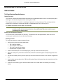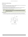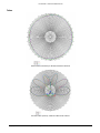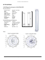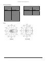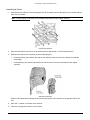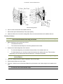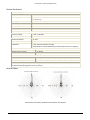
1
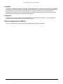
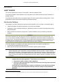
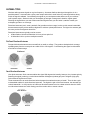
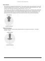
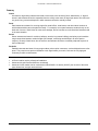
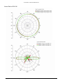
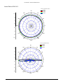
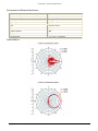
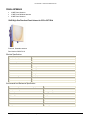
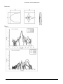
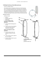
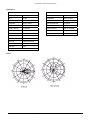
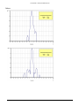
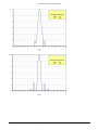
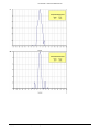
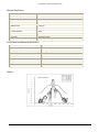
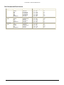
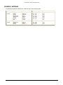
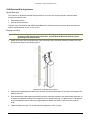
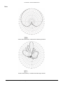
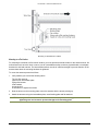
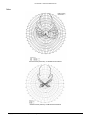
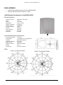
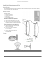
Part Number 72084 Tsunami MP.11 Recommended Antennas Version 2.3 Tsunami MP.11 Recommended Antennas Copyright © 2005 Proxim Wireless Corporation, San Jose, CA. All rights reserved. Covered by one or more of the following U.S. patents: 5,231,634; 5,875,179; 6,006,090; 5,809,060; 6,075,812; 5,077,753. This manual and the software described herein are copyrighted with all rights reserved. No part of this publication may be reproduced, transmitted, transcribed, stored in a retrieval system, or translated into any language in any form by any means without the written permission of Proxim Wireless Corporation. Trademarks Tsunami, Proxim, and the Proxim logo are trademarks of Proxim Wireless Corporation. All other trademarks mentioned herein are the property of their respective owners. SAFETY AND REGULATORY INFORMATION See the Tsunami MP.11 product CD for important Safety and Regulatory Information. Copyright © 2005 Proxim Wireless Corporation. All rights reserved. 2 Tsunami MP.11 Recommended Antennas Contents Safety and Regulatory Information................................................................................................................ 2 INTRODUCTION .......................................................................................................................................... 4 About This Book ............................................................................................................................................ 4 Antenna Types .............................................................................................................................................. 5 RECOMMENDED 5.8 GHZ ANTENNAS ..................................................................................................... 8 Omni-Directional Antennas ........................................................................................................................... 8 Sector Antennas.......................................................................................................................................... 13 Panel Antennas ........................................................................................................................................... 19 Parabolic Antennas ..................................................................................................................................... 32 RECOMMENDED 2.4 GHZ ANTENNAS ................................................................................................... 33 Omni Antennas............................................................................................................................................ 33 Sector Antennas.......................................................................................................................................... 41 Panel Antennas ........................................................................................................................................... 49 Parabolic Antennas ..................................................................................................................................... 53 SUPPORT................................................................................................................................................... 58 Copyright © 2005 Proxim Wireless Corporation. All rights reserved. 3 Tsunami MP.11 Recommended Antennas Introduction ABOUT THIS BOOK This manual supplements the Proxim Tsunami MP.11 Antenna Installation Guide. The Antenna Installation Guide explains how to install and set up an outdoor antenna with the Tsunami MP.11 hardware devices. This guide does not explain how to erect antenna masts, nor how to install a safety grounding system. These prerequisites must be in place before installing the directional antenna. Who Should Use This Manual The installation of outdoor wireless links requires technical expertise. At the very least, you should be able to: • Install and configure the network components, such as the radio hardware. • Understand, or have a working knowledge of, installation procedures for network operating systems using Microsoft Windows. • Mount the outdoor antenna and surge arrestor. Antenna installation must be provided by professional installers. WARNING! The outdoor antennas to be used with these products are intended for mounting on an antenna tower, on a roof, or on the side of a building. Installation is not to be attempted by someone not trained or experienced in this type of work. The antenna must be installed by a suitably trained professional installation technician or by a qualified antenna installation service. The site prerequisites must be checked by a person familiar with the national electrical code and with other regulations governing this type of installation. Local radio regulations or legislation may impose restrictions on the use of specific combinations of: • • Low-loss antenna cables and outdoor antennas Radio channels selected at the radios that are connected to specific outdoor antennas Note: A basic rule for selecting a combination of cables and antennas is that no combination is allowed unless explicitly approved in the Tsunami MP.11 Antenna Installation Guide for your MP.11 model. Therefore, always use Tsunami MP.11 Recommended Antennas in combination with “Chapter 2. Determining Range and Clearance” of the Antenna Installation Guide to select the correct type of antenna equipment and to inform your antenna installer and LAN administrator about the impact of regulatory constraints on their job or activities. CAUTION At all times, it is the customer’s responsibility to ensure that an outdoor antenna installation complies with local radio regulations.1 The customer must verify that: The antenna installer is aware of these regulations The correct cable type and surge arrestor have been used, according to the instructions described in this document Proxim Wireless Corporation and its resellers or distributors are not liable for any damage or violation of government regulations that may arise from failing to comply with these guidelines. 1 In case you are not certain about the regulations that apply in your country, consult your local Proxim Wireless Corporation Sales Office. Copyright © 2005 Proxim Wireless Corporation. All rights reserved. 4 Tsunami MP.11 Recommended Antennas ANTENNA TYPES Wireless radios generate signals on a given frequency. Antennas distribute that signal through the air in a particular pattern. Antennas take a given power output and make it reach further by reducing directions along which the signal is radiated. Concentrating the signal on your workspace makes better use of your wireless radio’s power output, Stations inside your workspace get stronger coverage and, therefore, higher speed. Directing the signal where you want it also means less signal where you don’t want it; stations outside your workspace get little or no coverage. Directional antennas (omni, sector, parabolic, flat) provide maximum range, but due to their narrow beamwidth, these antennas require precise antenna alignment to achieve optimal performance. The higher the antenna gain, the more precise the alignment should be. Directional antennas are typically used to connect: • • A Base Station Unit and a Subscriber Unit in a point-to-point link A Subscriber Unit in a point-to-multipoint network Flat Panel Directional Antennas Flat panel directional antennas are mounted flush on walls or ceilings. They produce hemispherical coverage, spreading away from the mount point at a width of 30 to 180 degrees. Concentrating the signal on this smaller area further increases range. Flat Panel Horizontal Vertical Omni-Directional Antennas Like dipole antennas, Omni antennas radiate the signal 360 degrees horizontally; however, they increase gain by flattening the signal, producing a vertical beam between 80 degrees (modest gain) and 7 degrees (high gain). Gain makes the signal travel further. These antennas have an omni-directional azimuth pattern that makes them easy to install. There is also a gainto-beamwidth relation for omni-directional antennas: The higher the gain of the omni-antenna, the narrower the vertical beamwidth. In a hilly terrain, an 8 dBi omni-directional antenna can be a better solution than the 10 dBi omni-directional antenna to avoid missing part of the terrain with too narrow a beam. Omni Antenna Horizontal Vertical Copyright © 2005 Proxim Wireless Corporation. All rights reserved. 5 Tsunami MP.11 Recommended Antennas Sector Antennas Sector antennas are high-gain directional antennas. These cylinders contain a boom supporting thin vertical rods. The signal propagates off the front of the boom. Note that some signal (back lobes) fall behind the boom. Sector antennas create higher gain by producing narrower beams (20 – 80 H, 14 – 64 V). The wide-angle sector antenna is a good Base Station antenna for hilly terrain. It combines a wide opening angle “sector” with relatively high gain. The mounting brackets allow tilting of the antenna. This antenna also is used when the amount of traffic in a cell is too high for a single Base Station with an omni-directional antenna. The wide-angle antenna allows dividing the cell into three sectors that each can be serviced by a Base Station. Sector Antenna Horizontal and Vertical Parabolic Dish Antennas Parabolic antennas are concave panels or bowls that produce an extremely narrow beam (4 – 25 degrees horizontal / vertical). Parabolic Antenna Horizontal and Vertical Copyright © 2005 Proxim Wireless Corporation. All rights reserved. 6 Tsunami MP.11 Recommended Antennas Summary Omnis Are better for high-ceiling industrial and retail environments, such as factory floors, warehouses, or “big box” stores in which antennas can be suspended from the ceiling at the center of large open areas. But Omnis are not good in long, narrow workspaces in which antennas cannot be centrally located. Panel Panel antennas are better for covering single-floor small offices, small stores, and other indoor locations in which wireless radios cannot be placed centrally. For example, mount panel antennas unobtrusiovely on the back wall of a store. Back lobes do create some leakage, but far less than an omni-directional antenna would in the same situation. Sector Sector antennas are better for corridors, hallways, tunnels, long narrow buildings, and point-to-point medium range connections between outdoor bridges (for example, connecting two buildings in an office park or campus). Be wary of back lobes, but the sector’s narrow beam will reduce unwanted peripheral exposure in the focal direction. Parabolic Parabolic antennas are better for long-range outdoor point-to-point connectors, such as bridges that are miles apart. They require more precise installation to aim signal where you want it, but have the very high gain necessary to reach such distances. Notes: • • • All Proxim radios require professional installation. Antennas with gain less than 8 dBi are not allowed. Antennas of other makes can be used with the HZB-US5358-11A device (5054-R), but must be of the same type, dimensions, and gain as those listed. Copyright © 2005 Proxim Wireless Corporation. All rights reserved. 7 Tsunami MP.11 Recommended Antennas Recommended 5.8 GHz Antennas • • • • Omni-Directional Antennas Sector Antennas Flat Panel Antennas Parabolic Antennas OMNI-DIRECTIONAL ANTENNAS • • • 8 dBi Omni-Directional Antenna (5054-OA-8) 10 dBi Omni-Directional Antenna (5054-OA-10) Other Recommended Omni Antennas 8 dBi Omni-Directional Antenna (5054-OA-8) Electrical Specifications Part Number 5054-OA-8 Frequency Range 5470 MHz – 5875 MHz VSWR 2.0 : 1 maximum Nominal Impedance 50 ohms Average/Peak Gain 7.8/9.0 dBi @ 5.5 GHz HPBW/horizontal 360 degrees HPBW/vertical 12 degrees Polarization Linear, vertical Electrical Downtilt 2 degrees Power handling 5W (cw) Connector type Standard N female 8.1/9.4 dBi @ 5.7 GHz Environmental and Mechanical Specifications Wind Survival (per EIA-222-F at 100’ height) 216 km/hr Temperature range -40 to +90 degrees C Humidity 95% @ 25 degrees C Lightning protection DC ground Size 78 x 80 x 384 mm Radome color Gray-white Radome material Fiberglass Weight 230 g Copyright © 2005 Proxim Wireless Corporation. All rights reserved. 8 Tsunami MP.11 Recommended Antennas Antenna Patterns 5054-OA-8 Copyright © 2005 Proxim Wireless Corporation. All rights reserved. 9 Tsunami MP.11 Recommended Antennas 10 dBi Omni-Directional Antenna (5054-OA-10) Part Number 5054-OA-10 Electrical Specifications Electrical Frequency Range 5470 MHz – 5875 MHz GHz VSWR 2.0 : 1 maximum Nominal Impedance 50 ohms Gain 10 dBi HPBW/horizontal 360 degrees HPBW/vertical 6 degrees Polarization Linear, vertical Downtilt 2 degrees Power handling 5W (cw) Connector Standard N female Environmental and Mechanical Specifications Wind Survival (per EIA-222-F at 100’ height) 216 km/hr Temperature range -40 to +90 degrees C Humidity 95% @ 25 degrees C Lightning protection DC ground Size 78 x 80 x 515 mm Radome color Gray-white Radome material Fiberglass Weight 270 gw Copyright © 2005 Proxim Wireless Corporation. All rights reserved. 10 Tsunami MP.11 Recommended Antennas Antenna Patterns 5054-OA-10 H-plane Co-polarization Pattern 90 120 10 60 5500 MHz 5600 MHz 5700 MHz 5800 MHz 5 30 150 0 -5 180 0 -5 0 330 210 5 10 240 300 270 V-plane Co-polarization Pattern 90 120 10 60 5500 MHz 5600 MHz 5700 MHz 5800 MHz 5 30 150 0 -5 180 0 -5 0 330 210 5 10 240 300 270 Copyright © 2005 Proxim Wireless Corporation. All rights reserved. 11 Tsunami MP.11 Recommended Antennas Other Recommended Omni Antennas Type Manufacturer Model Number Frequency Range Mid-Band Gain Omni Mars MTI MTI MTI Stella Doradus Stella Doradus Stella Doradus Stella Doradus Stella Doradus Stella Doradus Telex RadioWaves MA-WO58-9X MT-482003/N MT-482009/N MT-483003/N 52 1360 52 2360 52 3360 58 1360 58 2360 58 3360 5830 OMN-H-5-8 5.47 – 5.875 5.15 – 5.875 5.725 – 5.875 5.725 – 5.875 5.1 – 5.3 5.1 – 5.3 5.1 – 5.3 5.7 – 5.8 5.7 – 5.8 5.7 – 5.8 5.725 – 5.85 5.725 – 5.85 9 9 12 12 7 10 13 7 10 13 7.5 8 (hor pol) Copyright © 2005 Proxim Wireless Corporation. All rights reserved. 12 Tsunami MP.11 Recommended Antennas SECTOR ANTENNAS • • 14 dBi Sector 120 degrees 17 dBi Sector Antenna (60°) 14 dBi Sector Antenna (120°) 5054-SA120-14 Electrical Specifications Frequency Range 5150 MHz – 5875 MHz VSWR 2.0 : 1 maximum Nominal Impedance 50 ohms Gain 13.5 dBi HPBW/horizontal 120 degrees HPBW/vertical 6 degrees Polarization Linear, vertical Downtilt 0 degrees Power handling 5W (cw) Connector N-type Female Copyright © 2005 Proxim Wireless Corporation. All rights reserved. 13 Tsunami MP.11 Recommended Antennas Environmental and Mechanical Specifications Wind Survival (per EIA-222-F at 100’ height) 216 km/hr Temperature range -40 to +80 degrees C Humidity 95% @ 25 degrees C Lightning protection DC ground Size 620 x 88 x 70 mm Radome color Gray, white Radome material ABS Weight 590 gw Mechanical tilt +10 .. 0 or 0.. –10 degrees Mechanical Layout Copyright © 2005 Proxim Wireless Corporation. All rights reserved. 14 Tsunami MP.11 Recommended Antennas Antenna Patterns 5054-SA120-14 Copyright © 2005 Proxim Wireless Corporation. All rights reserved. 15 Tsunami MP.11 Recommended Antennas 17 dBi Sector Antenna (60°) Part Number 5054-SA60-17 Electrical Specifications Frequency Range 5150 MHz – 5875 MHz VSWR 2.0 : 1 maximum Nominal Impedance 50 ohms Gain 16.5 dBi HPBW/horizontal 60 degrees HPBW/vertical 6 degrees Polarization Linear, vertical Downtilt 0 degrees Power handling 5W (cw) Connector N-type Female Copyright © 2005 Proxim Wireless Corporation. All rights reserved. 16 Tsunami MP.11 Recommended Antennas Environmental and Mechanical Specifications Wind Survival (per EIA-222-F at 100’ height) 216 km/hr Temperature range -40 to +90 degrees C Humidity 95% @ 25 degrees C Lightning protection DC ground Size 620 x 88 x 70 mm Radome color Gray, white Radome material ABS Weight 565 gw Mechanical tilt +10 .. 0 or 0.. –10 degrees Antenna Patterns Copyright © 2005 Proxim Wireless Corporation. All rights reserved. 17 Tsunami MP.11 Recommended Antennas Other Recommended Sector Antennas Type Manufacturer Model Number Frequency Range Mid-Band Gain Sector 60 degrees Mars MTI MTI MTI RadioWaves RadioWaves MA-WC50-5X MT-484026/NV MT-484026/NH MT-484033/NV SEC-55H-60-17 SEC-55V-60-17 5.15 – 5.85 5.15 – 5.875 5.15 – 5.875 5.15 – 5.875 5.25 – 5.85 5.25 – 5.85 17 16 (Null-Fill) 15 (h pol, NF) 16.5 17 (hor pol) 17 Sector 90 degrees Mars MTI MTI MTI RadioWaves RadioWaves Telex Telex MA-WD50-6X MT-484027/NV MT-484027/NH MT-484032/NV SEC-55H-90-16 SEC-55V-90-16 5801 5840 5.15 – 5.875 5.15 – 5.875 5.15 – 5.875 5.15 – 5.85 5.25 – 5.85 5.25 – 5.85 5.725 – 5.825 5.725 – 5.825 16 14 (Null-Fill) 14 (h pol, NF) 17 16 (hor pol) 16 12 15 Sector 120 degrees Mars MTI MTI RadioWaves RadioWaves MA-WE50-7X MT-484034/NV MT-484034/NH SEC-5V-120-14 SEC-5V-120-16 5.15 – 5.875 5.15 – 5.875 5.15 – 5.875 5.725 – 5.85 5.725 – 5.85 14.5 16.5 16.5 (hor pol) 14 16 Copyright © 2005 Proxim Wireless Corporation. All rights reserved. 18 Tsunami MP.11 Recommended Antennas PANEL ANTENNAS • • • 18 dBi Panel Antenna 15 dBi Panel Window Antenna 23 dBi Panel Antenna 18 dBi High Gain Directional Panel Antenna for 5.25 to 5.875 GHz Pictured: SmartAnt antenna Part Number 5054-PA-18 Electrical Specifications Frequency Range 5.25 GHz – 5.785 GHz VSWR 1.5: 1 maximum Nominal Impedance 50 ohms Gain 18 dBi HPBW/horizontal 18 degrees HPBW/vertical 18 degrees Polarization Linear, vertical Downtilt 0 degrees Power handling 10W (cw) Connector Standard N female Front-to-back ratio 30 dB Environmental and Mechanical Specifications Wind Survival (per EIA-222-F at 100’ height) 216 km/hr Temperature range -40 to +80 degrees C Humidity 95% @ 25 degrees C Lightning protection DC ground Size 200 x 200 x 50 mm Radome color Black Radome material ABS, UV resistant Weight 0.825 kgw Copyright © 2005 Proxim Wireless Corporation. All rights reserved. 19 Tsunami MP.11 Recommended Antennas Dimensions Patterns Copyright © 2005 Proxim Wireless Corporation. All rights reserved. 20 Tsunami MP.11 Recommended Antennas Copyright © 2005 Proxim Wireless Corporation. All rights reserved. 21 Tsunami MP.11 Recommended Antennas 15 dBi High Gain Directional Panel (Window) Antenna Pictured: SmartAnt antenna This window antenna is a high-gain antenna for the 5 GHz frequency band. This antenna is typically used in combination with a Subscriber Unit. The red heat-shrink tube at the antenna connector of this antenna matches the red heat-shrink tube at the MP.11a antenna connector to easily locate and distinguish the 5 GHz antenna components from their look-alikes operating at 2.4 GHz which do not have red heat-shrink tube. Mounting Instructions Package contents: • • • • Antenna Extension Cable (3m) Mounting Kit Quick Installation Guide Wall Mount for Outdoor/Indoor Application A. Insert the plastic wall plug (2) into the wall B. Insert the screw (3) into the plastic wall plug through the antenna mounting hole and tighten Window Suction Mount for Indoor Application A. Insert the window suction cup through the antenna mounting hole. B. Turn the suction cup one quarter to lock it into position. C. Press the window suction cup onto the window glass. Copyright © 2005 Proxim Wireless Corporation. All rights reserved. (1) Antenna body (2) plastic conical anchor (3) screw (4) window suction cup 22 Tsunami MP.11 Recommended Antennas Specifications Electrical Environmental and Mechanical Frequency range 5150 MHz – 5850 MHz Survival wind speed 180 km/hr Gain* 15 dBi Temperature -40º C to +80º C VSWR 2.0 : 1 Max. Humidity 95% @ 25º C Polarization Linear, vertical Lightning Protection DC ground HPBW / horizontal 45 degrees Radome color white HPBW / vertical 10 degrees Radome material ABS, UV resistant Front to back ratio 18 dB Weight 0.6 kgw Downtilt 0 degrees Dimensions 330 x 93 x 21 mm Power handling 20 W (cw) Impedance 50 Ohms Connector Standard N-female Cable ULA-168; 200 cm Cable loss 2 dB *exclusive of cable loss Pattern Copyright © 2005 Proxim Wireless Corporation. All rights reserved. 23 Tsunami MP.11 Recommended Antennas 23 dBi Broadband Subscriber Panel Antenna MA-WA58-1X This 5 GHz Broadband Antenna provides a cost effective solution for large scale WLL, WLAN, H-LAN, ISM, UNII, and Point to Multi Point applications. Additional Features: • • • Minimum Gain of 23 dBi over the entire frequency range. Light weight and durable construction. DC grounded for lightning protection to meet local electrical building codes. Specifications Electrical Frequency range 5.15 - 5.875 GHz GAIN, typ. 23 dBi VSWR, max. 1.5:1 Polarization Linear Vertical 3 dB Beam Width - Az./El., typ. 10.5 degrees Cross Polarization, min 24 dB Power Handling 10 Watts Input Impedance 50 Ohms Front to Back Ratio, min. 35 dB Mechanical and Environmental Dimensions (LxWxD) 305x305x15 mm (DIAMOND Shape) Base Plate Aluminum, Coated Radome Plastic, UV protected Temperature -40 degrees C up to +75 degrees C Input/RF Interface N-Type (others available) Standard Compliance ETSI EN 302 085 V1.1.2 (2001-02) Range 1, TS 1, 2, 3, 4, 5 Specifications subject to change without notice Copyright © 2005 Proxim Wireless Corporation. All rights reserved. 24 Tsunami MP.11 Recommended Antennas Patterns Copyright © 2005 Proxim Wireless Corporation. All rights reserved. 25 Tsunami MP.11 Recommended Antennas Copyright © 2005 Proxim Wireless Corporation. All rights reserved. 26 Tsunami MP.11 Recommended Antennas Copyright © 2005 Proxim Wireless Corporation. All rights reserved. 27 Tsunami MP.11 Recommended Antennas 23 dBi High Gain Directional Panel Antenna for 5.8 GHz (5054-PA-23) Pictured: SmartAnt antenna Package Contents • • • • • • Antenna Extension Cable (50cm) Mounting Kit Surge Arrestor Water-proof tape Quick Installation Guide Mounting 5. 6. 7. 8. 9. 10. 11. 12. 13. Mounting base, 1 PC M4*8 screw+W+S/W-4 PCS Space keeper – 4 pcs M-shape mounting – 1 pc ¾” screw – 4 pcs Plastic wallplug – 4 pcs M6*16 screw – 4 pcs M6 S/W – 4 pcs M6 W – 4 pcs 1. 2. 3. 4. 5. 6. 7. 8. 9. Mounting base, 1 PC M4*8 screw+W+S/W-4 PCS Space keeper – 4 pcs M-shape mounting – 1 pc Pole mount clip – 1 pc M6*60 screw – 2 pcs M6*16 screw – 4 pcs M6 S/W – 4 pcs M6 W – 4 pcs Copyright © 2005 Proxim Wireless Corporation. All rights reserved. 28 Tsunami MP.11 Recommended Antennas Electrical Specifications Frequency Range 5725 - 5875 MHz Nominal Impedance 50 ohms Gain 23 dBi Front-to-Back Ratio 40 dB HPBW/vertical 9 degrees HPBW/horizontal 9 degrees Cross Polarization 25 dB Power handling 20 W (cw) Connector Standard N female VSWR 1.5: 1 maximum Environmental and Mechanical Specifications Wind Survival (per EIA-222-F at 100’ height) 216 km/hr Temperature range -40 to +80 degrees C Humidity 95% @ 25 degrees C Lightning protection DC ground Size 360 x 360 x 16 mm Weight 1.6 kgw Radome material ABS, UV resistant Radome color white Patterns Copyright © 2005 Proxim Wireless Corporation. All rights reserved. 29 Tsunami MP.11 Recommended Antennas Copyright © 2005 Proxim Wireless Corporation. All rights reserved. 30 Tsunami MP.11 Recommended Antennas Other Recommended Panel Antennas Type Manufacturer Model Number Frequency Range Mid-Band Gain Panel SmartAnt Gabriel MTI MTI MTI Mars Radiowaves R0320-056 DFPS.5-52 MT-485001/N MT-485028/N MT-486004/N MA-WA57-3X FP .5-5-18 5.15 – 5.875 5.25 – 5.85 5.15 – 5.875 5.15 – 5.875 5.15 – 5.875 5.15 – 5.875 5.25 – 5.85 8 18 18 22 26 17.5 18 1-Foot Flat Panel Gabriel Andrew MTI Mars RadioWaves DFPD1-52 FPA5250D12-N 485002/N MA-WA58-1X FP1 5-24 5.25 – 5.85 5.25 – 5.85 5.15 – 5.875 5.15 – 5.875 5.25 – 5.85 23.5 23.6 23 23 24 2-Foot Flat Panel MTI Gabriel Andrew RSI RadioWaves MT-486001/N DFPD2-52 FPA5250D24-N A57A24-U FP2 5-28 5.15 – 5.875 5.25 – 5.85 5.25 – 5.85 5.725 – 5.85 5.25 – 5.85 28 28 28.2 26.5 28 Copyright © 2005 Proxim Wireless Corporation. All rights reserved. 31 Tsunami MP.11 Recommended Antennas PARABOLIC ANTENNAS Recommended parabolic antennas for 5 GHz are listed in the following table. Type Manufacturer Model Number Frequency Range Mid-Band Gain 2-Foot Parabolic Gabriel Gabriel Gabriel Radio Waves Radio Waves Andrew Andrew RSI SSP2-52B SSD2-52A HSSP2-52 SP2-5.2 SPD2-5.2 P2F-52 PX2F-52 P-57C24 5.25 – 5.85 5.25 – 5.85 5.25 – 5.85 5.25 – 5.85 5.25 – 5.85 5.25 – 5.85 5.25 – 5.85 28.5 28.4 28.1 28.3 28.1 29.4 29.4 29 3-Foot Parabolic Radio Waves Radio Waves Andrew Andrew SP3-5.2 SPD3-5.2 P3F-52 PX3F-52 5.25 – 5.85 5.25 – 5.85 5.25 – 5.85 5.25 – 5.85 31.4 31.1 33.4 33.4 Copyright © 2005 Proxim Wireless Corporation. All rights reserved. 32 Tsunami MP.11 Recommended Antennas Recommended 2.4 GHz Antennas OMNI ANTENNAS 7 dBi Omni-Directional Base Unit Antenna General Description The Tsunami 7 dBi Omni-Directional Base Unit Antenna is a broadband antenna for the 2.4 GHz frequency band featuring an omni-directional pattern with a nominal gain of 7 dBi. The pole-type antenna is enclosed in a weatherproof protective covering (“radome”). This vertically polarized antenna can be mounted to an antenna mast with an outside diameter of up to 65 mm (2.5 in). For detailed specifications see the table in this appendix. DANGER! When selecting an antenna location, ensure that the general precautions are met to avoid possible contact with electrical power lines. See the National Electrical Code for proper grounding of the antenna mast Mounting the Omni-directional Antenna You can mount the 7 dBi antenna to a mast only. This antenna uses vertical polarization, which is the most common type of polarization for omni-directional antennas. Mounting to a Mast To mount the antenna to a mast proceed as follows: 1. Verify that you have all the items listed below: º º º º The 7 dBi Pole Antenna The O-shaped metal bracket The U-bolt, nuts and lock washers A small wrench to tighten the nuts 2. Position the bracket (item d in the following figure) to the top of the antenna mast (item b). 3. Place the U-bolt (item c) around the antenna mast, and slide its ends through the corresponding holes of the bracket. 4. Use the lock-washers (item e) and nuts (item f) to secure the bracket to the mast. Use a wrench to tighten the nuts. 5. Next, feed the antenna cable of the 7 dBi Omni-Directional Base Unit Antenna (item a) through the hole of the mounting bracket. 6. As shown in the following figure, slide the antenna down until its metal base is enclosed by the mounting bracket. Copyright © 2005 Proxim Wireless Corporation. All rights reserved. 33 Tsunami MP.11 Recommended Antennas Mounting the 7 dBi Antenna to a Mast 7. Use a wrench to tighten the bracket bolt (item g) to fix the antenna into its position. CAUTION! Avoid over-tightening the hose-clip nut to avoid damage to the clip and your antenna. Technical Specifications Mechanical Size 43.2 cm (17 in) Mounting method Clamps to vertical mast with outside diameter between 35 mm (1.4 in) and 65 mm (2.55 in) Connector1 Standard N (female) Electrical Frequency Range 2.400 – 2.484 GHz VSWR Less than 2:1 nominal Nominal Impedance 50 ohms Gain 7 dBi Polarization Linear vertical Antenna Environment Operating temperature -40 degrees C (-40 degrees F) to +60 degrees C (+140 degrees F) Wind/survival At least 200 km/h (124 mph)2 1 See also “Selecting the Correct Connector Type”. 2 At least 100 km/h (62 mph) with 1.25 cm (0.5 in) ice. Copyright © 2005 Proxim Wireless Corporation. All rights reserved. 34 Tsunami MP.11 Recommended Antennas Pattern Azimuth Plane (Horizontal), 7 dBi Omni-Directional Base Unit Antenna Elevation Plane (Vertical), 7 dBi Omni-Directional Base Unit Antenna Copyright © 2005 Proxim Wireless Corporation. All rights reserved. 35 Tsunami MP.11 Recommended Antennas 10 dBi Omni-Directional Base Unit Antenna General Description The Tsunami 10 dBi Omni-Directional Base Unit Antenna is a broadband antenna for the 2.4 GHz frequency band featuring an omni-directional pattern with a nominal gain of 10 dBi. This antenna is typically used in combination with a Base Unit. The pole-type antenna is enclosed in a weatherproof protective covering (“radome”). This vertically polarized antenna can be mounted to an antenna mast with an outside diameter of up to 51 mm (2.0 in). For detailed specifications see the table in this appendix. DANGER! When selecting an antenna location, ensure that the general precautions are met to avoid possible contact with electrical power lines. See the National Electrical Code for proper grounding of the antenna mast Mounting Instructions 1. Attach the ferrule of the antenna to the mounting bracket with two U-bolts as shown in the following figure. 2. Next use the remaining two U-bolts to attach the mounting bracket to the mast. Tighten nuts to 9 Nm (7 ft-lbs). Mounting the 10 dBi Antenna Copyright © 2005 Proxim Wireless Corporation. All rights reserved. 36 Tsunami MP.11 Recommended Antennas Technical Specifications Mechanical Size 91.4 cm (36 in) Mounting Method Clamps to vertical mast with outside diameter between 35 mm (1.4 in) and 51 mm (2.0 in) Connector1 Standard N (female) Cable Type RG-303, 50 ohms low-loss coaxial Length 25 cm (10 in) Color Tan Electrical Frequency Range 2..4 GHz VSWR Less than 2:1 nominal Nominal Impedance 50 ohms Gain 10 dBi Polarization Linear vertical Antenna Environment Operating Temperature -40 degrees C (-40 degrees F) to +60 degrees C (+140 degrees F) Wind/survival (mph) At least 240 km/h (150 mph)2 1 See also “Selecting the Correct Connector Type”. 2 At least 200 km/h (124 mph) with 1.25 cm (0.5 in) ice. Copyright © 2005 Proxim Wireless Corporation. All rights reserved. 37 Tsunami MP.11 Recommended Antennas Pattern Azimuth Plane (Horizontal), 10 dBi Omni-Directional Base Unit Antenna Elevation Plane (Vertical), 10 dBi Omni-Directional Base Unit Antenna Copyright © 2005 Proxim Wireless Corporation. All rights reserved. 38 Tsunami MP.11 Recommended Antennas 5 dBi Omni-Directional Antenna General Description The Tsunami 5 dBi Omni-Directional Antenna is designed for use in rugged environments. The antenna operates in the frequency range from 1500 to 2400 MHz. It is supplied with a special proprietary FCC plug and a low-loss cable. This antenna uses vertical polarization, which is the most common type of polarization for omni-directional antennas. Technical Specifications Mechanical Size 24 cm (9.5 in) Mounting Method Through a 19 mm (0.75 in) M-type hole using a mounting plate. Connector Standard N female1 snap-on with 100% captive pin Cable Type 50 ohms low-loss cable Length 2.5 m (8 ft.) Color White Electrical Frequency Range 2.400 to 2.4835 GHz VSWR Less than 2:1 nominal Nominal Impedance 50 ohms Gain 5 dBi Polarization Linear vertical Antenna Environment Operating Temperature -40 degrees C (-40 degrees F) to +60 degrees C (+140 degrees F) Wind/survival At least 200 km/h (124 mph)2 1 2 See also “Selecting the Correct Connector Type” in the Antenna Installation Guide. At least 100 km/h (62 mph) with 1.25 cm (0.5 in) ice. Copyright © 2005 Proxim Wireless Corporation. All rights reserved. 39 Tsunami MP.11 Recommended Antennas Pattern Azimuth Plane (Horizontal), 5 dBi Omni-Directional Antenna Elevation Plane (Vertical), 5 dBi Omni-Directional Antenna Copyright © 2005 Proxim Wireless Corporation. All rights reserved. 40 Tsunami MP.11 Recommended Antennas SECTOR ANTENNAS 14 dBi 65-Degree Sector Antenna for 2.4 GHz PRX04-053970 Electrical Specification Frequency range Gain VSWR Polarization HPBW / horizontal HPBW / vertical Front to back ratio Downtilt Power handling Impedance Connector 2400 MHz - 2500 MHz 14 dBi 1.8 : 1 Max. Linear, vertical 65 degrees 13 25 dB 0 degrees 5 W (cw) 50 ohms N Jack Evironmental & Mechanical Characteristics Survival wind speed Temperature Humidity Radome color Radome material Weight Dimensions 180 km/hr - 40 deg. C to +80 deg. C 100% @ 25 degrees C Gray-white ABS, UV resistant 5.55 kg 600 x 88 x 70 mm Pattern Copyright © 2005 Proxim Wireless Corporation. All rights reserved. 41 Tsunami MP.11 Recommended Antennas 12 dBi Directional Wide Angle Antenna General Description The Tsunami 12 dBi Directional Wide Angle Antenna is for the 2.4 GHz frequency band is a perfect match between the features of the: • • Directional antennas Omni-directional antennas Typically used in combination with a Base stationBase Unit, this antenna can be mounted to an antenna mast with an outside diameter of up to 51 mm (2.0 in). Mounting Instructions DANGER! When selecting an antenna location, ensure that the general precautions are met to avoid possible contact with electrical power lines. See the National Electrical Code for proper grounding of the antenna mast. 1. Attach the U-bolts, tube mounting bracket, upper mounting bracket, and lower mounting bracket to the mast and spaced as shown in the following figure. Mounting the 12 dBi Wide Angle Antenna 2. Assemble the angle adjustment brackets to the upper mounting bracket with 1/2 inch bolts, lock washers, flat washers and nuts. 3. Next assemble the angle adjustment brackets and lower mounting brackets to the antenna base plate with 1/2 inch bolts, lock washers, and nuts.This adjustment is for 0 degree mounting. To adjust from 0 to -20 degrees, loosen the hardware at both ends of the angle adjustment bracket and slide it in the slot to the preferred angle. 4. Tighten hardware securely. The U-bolts should be tightened to 9 Nm (7 ft-lbs). Copyright © 2005 Proxim Wireless Corporation. All rights reserved. 42 Tsunami MP.11 Recommended Antennas Technical Specifications Mechanical Size (LxWxD) 181 x 53.7 x 76 cm (21.1 x 7.1 x 3.0 in) Mounting Method Clamps to vertical mast with outside diameter between 35 mm (1.4 in) and 51 mm (2.0 in) Connector1 Standard N (female) Electrical Frequency Range 2.400 – 2.484 GHz VSWR Less than 2:1 nominal Nominal Impedance 50 ohms Gain 12 dBi Polarization Linear vertical Half-Power Beamwidth (at vertical polarization) Elevation Plane (vertical) 13 degrees Azimuth Plane (horizontal) 125 degrees Antenna Environment Operating Temperature -40 degrees C (-40 degrees F) to +60 degrees C (+140 degrees F) Wind/survival (mph) At least 200 km/h (124 mph)2 1 See also “Selecting the Correct Connector Type”. 2 At least 100 km/h (62 mph) with 1.25 cm (0.5 in) ice. Copyright © 2005 Proxim Wireless Corporation. All rights reserved. 43 Tsunami MP.11 Recommended Antennas Pattern Azimuth Plane (Horizontal), 12 dBi Directional Wide Angle Antenna Elevation Plane (Vertical), 12 dBi Directional Wide Angle Antenna Copyright © 2005 Proxim Wireless Corporation. All rights reserved. 44 Tsunami MP.11 Recommended Antennas 14 dBi Directional Antenna General Description 14 dBi Directional Antenna is a high-gain antenna for the 2.4 GHz frequency band. This antenna is typically used in combination with a Subscriber Unit. The 14 dBi Directional Antenna consists of a totally enclosed 16 element Yagi antenna that has been designed for point-to-point communications. It has a typical VSWR of 1.5:1 and is less than 2:1 over the entire frequency band. The gain is 14 dBi and the half-power beamwidth is 30 degrees. This antenna is normally mounted on a mast and is vertically polarized. Contents of the Antenna Box • • • • One encapsulated antenna Metal backing plate for the antenna 2 U-bolts, with 2 bolt heads (for mast mounting) 4 flat washers, and 4 nuts (to attach the antenna to the U-bolts or screws) Mounting the Directional Antenna You can mount the Tsunami 14 dBi Directional Antenna to a mast or a flat vertical surface, such as a wall. In most cases, mounting the antenna to a mast allows for more flexibility in adjusting the height and direction of the antenna to aim it at the opposite end of the wireless link. DANGER! When selecting an antenna location, ensure that the general precautions are met to avoid possible contact with electrical power lines. See the National Electrical Code for proper grounding of the antenna mast Mounting to a Mast To mount the antenna to a mast proceed as follows: 1. Verify if you have all the items listed below: º The Tsunami 2.4 GHz antenna º The 2 U-bolts and bolt heads provided º The 4 flat washers and 4 nuts provided º A socket wrench to tighten the nuts 2. Note the arrows on the mounting plate; mount the antenna with the arrows pointing up. 3. Attach the antenna to the mast as depicted in the following figure, using the U-bolts and bolt heads, the Metal Backing Plate and nuts. CAUTION! Always place flat washers between heads (or nuts) and the plastic mounting plate. Avoid over-tightening the nuts and screws to prevent damage to the mounting plate. Copyright © 2005 Proxim Wireless Corporation. All rights reserved. 45 Tsunami MP.11 Recommended Antennas Mounting 14 dBi Antenna to a Mast Mounting on a Flat Surface For mounting the antenna to a flat vertical surface, you must provide a smooth surface for the antenna mount. On wall surfaces such as brick, block or stucco, use an intermediate surface such as a plywood board or metal plate between the wall and antenna. The intermediate surface must be of sufficient strength to prevent distortion of the antenna base when the mounting hardware is tightened. To mount the antenna proceed as follows: 1. Verify whether you have all the following items: The 2.4 GHz antenna (optional) an intermediate plate 4 plugs and screws 4 flat washers An electric drill A screwdriver to tighten the screws 2. Note the arrows on the mounting plate; mount the antenna with the arrows pointing up. 3. Attach the antenna using the intermediate plate, metal backing plate and flat washers. CAUTION! Always use flat washers between the screws and the plastic mounting plate. Avoid overtightening nuts and screws to prevent damage to the mounting plate. Copyright © 2005 Proxim Wireless Corporation. All rights reserved. 46 Tsunami MP.11 Recommended Antennas Technical Specifications Mechanical Size 44.7 cm (18 in) Mounting method Vertical or horizontal mast with an outside diameter between 28 mm (1.102 in) and 41 mm (1.625 in) using U-bolts. Wall using plugs and screws Connector1 Standard N (female) Cable Type RG58A/U, 50 ohms low-loss coaxial Color White Electrical Frequency Range 2.4 GHz VSWR Less than 2:1, 1.5:1 nominal Nominal Impedance 50 ohms Gain 14 dBi Front-to-back ratio Greater than 20 dB Half-Power Beamwidth Elevation Plane (vertical) 30.8 degrees Azimuth Plane (horizontal) 31.4 degrees Polarization Linear vertical (standard mounting) Horizontal (when mounted differently; see “Mounting the Directional Antenna” on page 45). Antenna Environment Operating temperature -40 degrees C (-40 degrees F) to +60 degrees C (+140 degrees F) Wind/survival At least 200 km/h (124 mph)2 1 2 See also “Selecting the Correct Connector Type”. At least 100 km/h (62 mph) with 1.25 cm (0.5 in) ice. Copyright © 2005 Proxim Wireless Corporation. All rights reserved. 47 Tsunami MP.11 Recommended Antennas Pattern Azimuth Plane (Horizontal), 14 dBi Directional Antenna Elevation Plane (Vertical), 14 dBi Directional Antenna Copyright © 2005 Proxim Wireless Corporation. All rights reserved. 48 Tsunami MP.11 Recommended Antennas PANEL ANTENNAS • 14 dBi Directional Panel Antenna for 2.4 GHz PRX04-050250 • High Gain Panel Directional Antenna for 2.4 GHz 14 dBi Directional Panel Antenna for 2.4 GHz PRX04-050250 Electrical Specification Frequency range Gain VSWR Polarization HPBW / horizontal HPBW / vertical Front to back ratio Downtilt Power handling Impedance Connector 2400 MHz - 2500 MHz 14 dBi 1.5 : 1 Max. Linear, vertical 30 degrees 30 degrees 15 dB 0 degrees 10W (cw) 50 Ohms N female Environmental & Mechanical Characteristics Survival wind speed Temperature Humidity Lightning protection Radome color Radome material Weight Dimensions 216 km/hr – 40 degrees C to +80 degrees C 95% @ 25 degrees C DC ground Light gray ABS, UV resistant 0.4 kg 200 x 200 x 50 mm Pattern Copyright © 2005 Proxim Wireless Corporation. All rights reserved. 49 Tsunami MP.11 Recommended Antennas Mounting Copyright © 2005 Proxim Wireless Corporation. All rights reserved. 50 Tsunami MP.11 Recommended Antennas High Gain Panel Directional Antenna for 2.4 GHz General Description The 12 dBi window antenna is a high-gain antenna for the 2.4 GHz frequency band. This antenna is typically used in combination with a Subscriber Unit. Mounting Instructions Package contents: • • • • ANT24-1200 Antenna Extension Cable (3m) Mounting Kit Quick Installation Guide Wall Mount for Outdoor/Indoor Application A. Insert the plastic wall plug (2) into the wall B. Insert the screw (3) into the plastic wall plug through the antenna mounting hole and tighten Window Suction Mount for Indoor Application A. Insert the window suction cup through the antenna mounting hole. B. Turn the suction cup one quarter to lock it into position. C. Press the window suction cup onto the window glass. Coverage 1. Antenna body 2. plastic conical anchor 3. screw 4. window suction cup Note: The bulged side of the antenna must point to the Base Station. Copyright © 2005 Proxim Wireless Corporation. All rights reserved. 51 Tsunami MP.11 Recommended Antennas Hardware Specifications Electrical Specification Frequency range 2.400 – .2484 MHz Gain 12 dBi VSWR 2.0 : 1 Max. Polarization Linear, vertical HPBW / horizontal 84 degrees HPBW / vertical 23 degrees Front to back ratio 18 dB Downtilt 0 degrees Power handling 20 W (cw) Impedance 50 Ohms Connector N-Jack Cable ULA-168; 200 cm Cable loss 1.3 dB *Exclusive of cable loss Environmental & Mechanical Characteristics Survival wind speed 180 km/hr Temperature -40º C to +80º C Humidity 95% @ 25º C Lightning Protection DC ground Radome color white Radome material ABS, UV resistant Weight 0.6 kgw Dimensions 330 x 93 x 21 mm Pattern Copyright © 2005 Proxim Wireless Corporation. All rights reserved. 52 Tsunami MP.11 Recommended Antennas PARABOLIC ANTENNAS 24 dBi Directional Parabolic Grid Antenna General Description The Tsunami 24 dBi Directional Parabolic Grid Antenna is a broadband antenna for the 2.4 GHz frequency band. The grid-type antenna allows either horizontal or vertical mounting on an antenna mast with an outside diameter of up to 51 mm (2 in). This antenna typically is used in combination with a Subscriber Unit. Note: The 24 dBi Directional Parabolic Grid Antenna is not allowed in countries that adhere to the ETSI radio regulations (also France). In countries that adhere to the FCC regulations, use of this antenna is allowed only when operated with specific radio channels that can be set on the Tsunami MP.11. Kit Contents The 24 dBi Directional Parabolic Grid Antenna comes in two boxes with the following contents Feed Box: 1 Feed assembly 1 Sub-reflector 1 #6 x 1/2 inch stainless screw 2 Stainless 1/4 x 20 hex nuts 2 Stainless lock washers 2 Stainless carriage bolts Reflector Box: 2 Reflector halves 2 Stainless U-bolts 2 Mast clamps 1 Mounting ‘L’ shaped bracket 4 Keps nuts (4) #8-32 machine screws 6 Stainless 1/4 x 20 hex nuts 6 Stainless lock washers 2 Stainless carriage bolts 1 Stainless flat plate washer Note: Prior to installation, or climbing the roof, verify if all parts and components are included. If any part is missing or appears to be damaged, consult your authorized Proxim Tsunami reseller. Copyright © 2005 Proxim Wireless Corporation. All rights reserved. 53 Tsunami MP.11 Recommended Antennas Assembling the Antenna 1. Assemble the two reflector halves inserting the four #8-32 machine screws through the front. Secure with the keps nuts on the back. Note: Loosely tighten all hardware until completely assembled and then tighten securely. Assemble the Reflector 2. Place the sub-reflector on the front of the feed and secure with the #6 x 1/2 inch stainless screw. 3. Determine the polarity of the antenna (see the following figure). º Horizontal polarity, (the reflector ribs and the sub reflector at the front end of the antenna are aligned horizontally). º Vertical polarity: (the reflector ribs and the sub reflector at the front end of the antenna are aligned vertically). Determine Polarization Polarity of the antenna must always be the same as the polarity of the antenna on the opposite side of the link! 4. Place the ‘L’ bracket on the back of the antenna. 5. Insert two carriage bolts from the front to attach. Copyright © 2005 Proxim Wireless Corporation. All rights reserved. 54 Tsunami MP.11 Recommended Antennas Attach Mounting Bracket 6. Secure on the back with the lock washers and nuts. 7. Recheck the dipole feed assembly for the proper polarity. 8. Attach the feed on the front with 2 carriage bolts. Secure on the back with the lock washers and nuts. Mounting the Antenna DANGER! Installation of antenna near power lines is dangerous! Before you proceed, make sure you have read and understood the safety precautions. 1. Before climbing the roof, make sure you have: º The assembled antenna. º The U-bolts and mast clamps to mount the grid antenna to the mast. 2. Determine the desired alignment of the antenna: º º For horizontal alignment you need both U-bolts and the 4 lock washers and nuts. For tilted alignment, you use only a single U-bolt and two lock washers and nuts. This mounting method lets you mount the antenna with an elevation in 10 degrees increments. CAUTION! Tilted alignment is not suitable for environments where the antenna is subject to high wind conditions. 3. Place the U-bolt(s) around the mast as depicted in the previous figure. 4. Slide the mast clamps over the U-bolts. 5. Slide the ‘L’ bracket over the U-bolts and fasten the grid antenna to the U-bolts using the lock washers and nuts. Note: For tilted elevation mounting, use the flat plate washer on the adjustable tilt slot to mount and secure the antenna to the desired elevation angle. Copyright © 2005 Proxim Wireless Corporation. All rights reserved. 55 Tsunami MP.11 Recommended Antennas Technical Specifications Mechanical Size (HxWxD) 61.0x91.4x38.1 cm (24x36x15 in) Mounting method Clamps to vertical mast with outside diameter between 26 mm (1.102 in) and 51 mm (2.0 in) Cable Type RG-8A/U, 50 ohms low-loss coax Cable Length 60 cm (24 in) Cable Color Black Connector 1 Standard N (female) Electrical Frequency Range 2.400 – 2.484 GHz VSWR Less than 2:1 nominal Nominal Impedance 50 ohms Gain 24 dBi Polarization Linear vertical for standard mounting Horizontal when mounted differently (see “Mounting the Antenna” on page 55) Half-Power Beamwidth (at vertical polarization) Elevation Plane (vertical) 10 degrees Azimuth Plane (horizontal) 6.5 degrees Antenna Environment Operating Temperature -40 degrees C (-40 degrees F) to +60 degrees C (+140 degrees F) Wind/survival (mph) At least 200 km/h (124 mph)2 1 2 See also “Selecting the Correct Connector Type”. At least 100 km/h (62 mph) with 1.25 cm (0.5 in) ice. Horizontal Pattern Azimuth Plane (Horizontal), 24 dBi Directional Parabolic Grid Antenna Copyright © 2005 Proxim Wireless Corporation. All rights reserved. 56 Tsunami MP.11 Recommended Antennas Vertical Pattern Elevation Plane (Vertical), 24 dBi Directional Parabolic Grid Antenna Copyright © 2005 Proxim Wireless Corporation. All rights reserved. 57 Tsunami MP.11 Recommended Antennas Technical Support If you are having a problem using a Proxim WAN product and cannot resolve it with the information in the product documentation, gather the following information and contact Proxim Technical Support: • • • • What kind of network are you using? What were you doing when the error occurred? What error message did you see? Can you reproduce the problem? Be sure to obtain an RMA number before sending any equipment to Proxim for repair. To receive E-mail technical support, be sure to include the serial number of the product(s) in question. The serial number should be on the product and conform to the following format: ##AT######## or ##UT######## or ##R7########. We are unable to respond to your inquiry without this information. USA & Canada Customers Call Technical Support: WAN Toll Free 1-866-674-6626 or 408-542-5390 Hours: 6:00 AM to 5:00 PM M-F Pacific Time LAN Toll Free 1-866-674-6626 Hours: 24x7 International Customers Call Technical Support: WAN 408-542-5390 Hours: 6:00 AM to 5:00 PM M-F Pacific Time LAN 408-542-5390 Hours: 24x7 Search Knowledgebase: http://support.proxim.com/ Latest software and documentation: http://support.proxim.com/ Copyright © 2005 Proxim Wireless Corporation. All rights reserved. 58