1
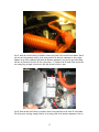
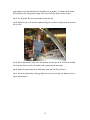
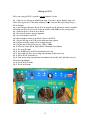
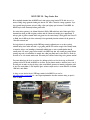
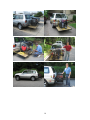
Interfacing the
Manzanita Micro PFC-50
to the
Toyota RAV4-EV
by the New Jersey RAV4-EV Team:
Duke Ahn
Lisa Mikulynec
David, Drew, and Joy Turock
Wally Urbanski
Revision 3 – July 31, 2007
Overview
The Manzanita Micro PFC-50 is a highly versatile electric vehicle charging device that accepts a wide range of input
voltages and currents. Connected to a 240VAC/50A circuit, it can fully charge the Toyota RAV4-EV in about 2.5 hours -less than half of the time required by the charger supplied with the vehicle. The PFC-50 can be connected to a
120VAC/15A or 120VAC/20A circuit as well, allowing any conventional electrical receptacle to serve as a charging
station. A full charge from a 120VAC/15A circuit is accomplished in approximately 18 hours.
Since the RAV4-EV can be driven while it is being charged by the PFC-50, coupling the charger with a mobile generator
converts the RAV4-EV into a serial Plug-in Hybrid Electric Vehicle with 100 miles of all-electric range (i.e., a PHEV-100)
and extends its continuous driving range by several hundred miles.
We describe a procedure for interfacing the PFC-50 with the RAV4-EV, and present our prototype implem entation of the
PHEV conversion / range extender.
Acknowledgments
William and Doug Korthof provided us with invaluable advice, without which we’d still be pouring through the Toyota
service manuals. Tom Dowling was also instrumental in guiding us through several PHEV conversion engineering issues.
Caveats
This procedure exposes you to hazardous and potentially fatal electrical current. If you’re not a licensed electrician
familiar with AC and DC high voltage systems, you will need to find one to perform the procedure for you. In addition,
this procedure is not authorized by Toyota, voids your warranty, and should be regarded as experimental. If you choose
to perform the procedure, you must assume all liability for personal injury and/or damage to your vehicle. Otherwise,
we respectfully require that you don’t read any further. Sorry about the legal disclaimers, but we don’t want anyone
getting hurt.
Calibrating Comments
The text below describes our implementation, based on the Korthof design. We made a number of choices along the
way that may or may not be consistent with your personal preferences and charging needs. Most parts of our
procedure may be modified, with a few notable exceptions. Where something must be implemented exactly as specified,
it is so indicated.
While there appear to be a lot of steps below, and this document appears large, the procedure desc ribed can be
accomplished in a few hours if you have the proper tools and have collected all of the necessary parts beforehand.
Parts List
To complete the installation, you will need the following:
Manzanita Micro PFC-50 charger, available from http://www.manzanitamicro.com
RAV4Info interface, from [email protected] (for monitoring battery temperatures and voltages).
Two GE circuit breakers part number EP100UC/EP102UCC63/673332, from http://livewiresupply.com
One Anderson SB175 connector from http://www.powerwerx.com
One 50A 240VAC weatherproof marine connector, part number 860010, from http://consumersmarine.com
One mating connector, part number 860018, from http://consumersmarine.com
One cover for mating connector, part number 860031, from http://consumersmarine.com
Your own extension cord (at least #8AWG is recommended) to connect to your power source.
30 feet of #8/0 AWG 600 volt wire with red insulator from any electrical store or Home Depot.
30 feet of #8/0 AWG 600 volt wire with black insulator
25 feet of flexible ½ inch diameter weatherproof conduit. Available at electrical supplies, Home Depot, or see
http://www.anacondasealtite.com/products.htm#Sealtite%AE%20Metallic%20Flexible%20Conduit%A0
5 conduit straps with self-tapping screws
One 14/50 surface mount range receptacle from an electrical supply or Home Depot
3 feet of #4/3 AWG 300 volt or better rated stranded cable
10 feet of quarter-inch wire protector
An exacto knife or sturdy box cutter with a sharp blade
Two #8 eye terminals for connecting #8 AWG wire to a bolt terminal
A tube of silicon seal
A dozen cable ties
5 feet of electrical solder
A roll of electrical tape
Required Tools
A torx wrench for opening the RAV4-EV’s electronics compartment, drill with metal-cutting bits, metric socket set with
socket extension, electrician’s pliers for cutting and splicing wire, small propane torch for soldering, and Phillips and
straight-head screw drivers.
2
The “Procedure:”
Step 1. Remove the traction battery service plug (labeled the Service Prug [sic]). This is located behind the driver’s seat
under the floor carpeting. Be sure that you aren’t wearing anything metal that could drop into the compartment after
you’ve pulled the plug (e.g., neck chain, etc.) Replace the metal door covering the service plug once you have removed
the plug.
3
Step 2. Remove the negative (black; labeled “-“) battery terminal from the 12v battery under the hood.
Step 3. Have a cup of coffee or a glass of water while you wait the mandatory 15 minutes required by the Toyota
service manual for appropriate capacitance discharge to occur in the vehicle’s electrical systems.
Step 4. Thread both #8 wires through the conduit. This is most easily accomplished if the conduit is laid out straight
before the conduit is routed under the vehicle. In other words, do what we say, not what we did!
Step 5. Remove the left access panel in the cargo bay area. Relocate the jack and the straps holding it in place to the
analogous compartment on the right side of the cargo bay. We use the left bay because the windshield washer tubes
for the rear window reside in the right bay and there is about to be a lot of electricity buzzing about this
compartment.
4
Step 6. Drill an appropriate sized hole for the marine connector (part 860010) using the template found in the
package. Connect one end of the 4/3AWG cord to the marine connector. Mount the connector as shown in the picture.
Connect the other end of the 4/3 cord to the surface mount 14/50 receptacle. Secure the 14/50 to the metal vent
chamber as in the pictured in Step 8, below. There are screw holes at the top of the vent chamber; you don’t need to
puncture the chamber to get a secure fit.
Step 7. Remove the screws holding the plastic liner on the left rear side of the cargo bay and expose the metal below.
Drill a 7/8 inch hole in the left rear underside of the RAV, as pictured below. Insert one side of the conduit from
under the car through the hole, and then guide it up behind the rear audio speaker so that it protrudes through the
access panel removed in Step 5.
5
Step 8. Terminate the wires at this end of the conduit on the load side of one of the GE breakers. Note that one
terminal on the breaker is labeled “+” and the other “-“. Place the red-insulated #8 wire on the positive (“+”)
terminal and the black-insulated #8 wire on the negative (“-“) terminal.
Step 9. Cut away a piece of the plastic large enough to match the ridges in the top and bottom of the front face of
the GE breaker as in the picture. Drill two holes large enough to fit a cable strap above and below the cut away.
6
Step 10. Cut two feet of the #8AWG red and two feet of the #8AWG black cable from the opposite side of the
conduit. Solder one side of these cable pieces to the Anderson SB175 connector. Note: The Anderson connector terminals
are large. We had to use a propane torch to achieve sufficient heat to melt the solder. It’s easier to hold Anderson lug
vertical, heat it, fill it 2/3 of the way up with molten solder, and then quickly insert the wire. Let the wire cool so
that you can hold it in your hand before mating it to the plastic housing. Insert the lug with the red cable in the side
of the plastic housing labeled “+” and the black cable in the side of the housing labeled “-“.
Step 11. Connect the ends of the cable opposite the Anderson connector to the line side of the GE breaker in the
cargo bay. Secure firmly. Cover these wires with the cable protector between the breaker and the Anderson connector.
Step 12. Be sure that no copper is exposed on either line or load side of the breaker.
Step 13. Insert cable ties through the holes you drilled above and below the breaker cutout. Grab the wires behind the
plastic and pull the cable ties tight and cut off the excess. This will hold the breaker in place. Apply silicon seal to the
top, bottom, and sides of the breaker, and over the screw leads.
Step 14. Apply a liberal amount of silicon seal in and around the area where you drilled the hole for the conduit.
Replace the screws in the plastic liner around the cargo bay.
Step 15. Route the conduit along the under side of the car up to the electronics module under the hood. Make certain
that you do not interfere with the movement of the shocks, wheels, etc., and that you do not press against any
hydraulic lines. The pictures below show one of the two routings that we used.
7
Step 16. Use the torx wrench to remove the cover of the electronics compartment. Marvel for a moment at the elegant
simplicity of the engineering in this electric vehicle.
Important note: It is imperative that you keep the inside of the electronics compartment free of all dirt, debris, metal
shavings, wire trimmings, and tools. When the car is re-energized, extremely high voltages will be present in here.
Leaving a screw driver or even a few strands of misplaced wire inside could create a huge problem.
Step 17. Using a volt meter set in a range appropriate for reading 250 to 350 volts direct current (VDC), verify that
there is no voltage present at the traction battery connection bolts in the upper right corner of the electronics
compartment.
8
Step 18. Using the box cutter, carefully cut a one-inch hole in the rubber boot on the right side of the electronics
compartment under the hood. Cut off any excess conduit from your run, so that the conduit terminates adjacent to the
hole in the boot.
Alternatively, you might want to use a tighter seal (note the upper right hand corner), although this complicates
removal of the top to the electronics unit.
9
Step 19. Insert the red and black wires through this opening, and carefully and gently pull the wire inside the
electronics compartment. Do not apply force to the plastic connectors near the boot opening. Route the wire around
the lower right corner of the electronics compartment as in the picture.
Step 20. Measure and trim the wires so that there is enough length to reach the breaker positioned as in the picture.
Terminate these wires on the “line” side of the second GE breaker. Note that this means that the breaker will be
upside down as you are facing it from the front of the car. Be sure that the red wire is connected to the (“+”)
terminal of the breaker and the black wire is connected to the (“-“) terminal.
10
Step 21. Solder an eye terminal to one end of the red wire trimmed off in Step 20.
Step 22. Solder an eye terminal to one end of the black wire trimmed off in Step 20.
Note: Perform the next two steps exactly as indicated. Do not attempt to connect your cables to any other terminals
other than the ones indicated, even though it might appear to make sense to do so. Connection as indicated is
necessary for the RAV4-EV’s computers to be aware of the power from the PFC-50.
Step 23. Using a 12mm socket, remove the nut holding down the top (positive, usually taped with red tape) traction
battery lead. Insert the eye terminal you just soldered to the red cable on the bolt. Replace the nut and tighten. The
picture below shows the bolt after the nut has been removed. Inspect the connection to ensure that no metal from
either the traction battery eye terminal or the eye terminal you have just installed is in contact with anything else
nearby.
11
Step 24. Using the 12mm socket, and an extension, remove the nut shown in the picture below. This one is tricky. If
you have big hands, find an agreeable volunteer with long, thin fingers to reach down and remove the nut. Insert the
eye terminal you just soldered to the black cable on this bolt. Replace the nut and tighten. Inspect the connection to
ensure that no metal from the eye terminal you have just installed is in contact with anything else nearby. We
wrapped our connector carefully with electrical tape just in case.
12
Step 25. Route the red wire from the eye terminal as shown in the picture to the second GE circuit breaker. Trim off
any excess wire being extremely careful to do the cutting outside of the electronics compartment so that no copper
fragments end up in the compartment. (We placed the electronics compartment’s cover over the space before making
each wire cut.) Attach the end of the red wire to the positive (“+”) terminal of the GE breaker. Place the protective
wire covering along the length of the red wire. Cable strap the wire to hold it in place.
Step 26. Route the black wire from the eye terminal as shown in the picture below to the second GE circuit breaker.
Trim off any excess wire being extremely careful to do the cutting outside of the electronics compartment so that no
13
copper fragments end up there. Attach the end of the black wire to the negative (“-”) terminal of the GE breaker.
Place the protective wire covering along the length of the red wire. Cable strap the wire to hold it in place.
Step 27. Turn the breaker “ON” (red is exposed when on; green when off).
Step 28. Replace the cover on the electronics compartment. Using the torx wrench tool, tighten down the screws that
hold it in place.
Step 29. Place a liberal amount of silicon seal on and around the area where you cut the 1 inch hole in the rubber
boot. Insert some silicon in the end of the conduit as well to prevent moisture from entering.
Step 30. Replace the negative terminal of the 12volt battery system, then close the hood of the car.
Step 31. Re-insert the traction battery service plug. Replace the cover of the service plug area, making sure that it is
properly latched into place.
14
Calibrating the PFC-50
The first step in using the PFC-50 is to perform a one-time calibration. To do this:
Step 1. Charge the car to full using the standard Toyota charger. If you prefer to have the Manzanita charge to the
bottom of your sag point, wait 12 hours before continuing to Step 2, so that your RAV’s traction battery will sag to
90% or thereabouts.
Step 2. Set the Manzanita’s DIP switches #1 and #7 to ON; everything else OFF. Note that the switches are numbered
in descending order (8,7,6,5,4,3,2,1) from left to right and that ON is actually DOWN, not UP as you might expect.
Step 3. Ensure that the car is off and the key is removed.
Step 4. Turn off the GE breaker in the cargo compartment.
Step 5. Turn off the breaker on the PFC-50.
Step 6. Mate the Anderson connector to the Anderson connector on the PFC-50.
Step 7. Plug the 14/50 plug on the PFC-50 into the surface mount range receptacle.
Step 8. Plug your favorite high capacity cord into the marine connector.
Step 9. Plug the other end into a power source (e.g., 120VAC or 240VAC)
Step 10. Start the car. Confirm that the “Ready” indication is illuminated on the dashboard.
Step 11. Turn on the GE breaker.
Step 12. Turn the AMPS knob on the PFC-50 counterclockwise until it stops.
Step 13. Using a small screw driver, turn the voltage trim potentiometer clockwise until it stops.
Step 14. Turn the PFC-50’s circuit breaker on.
Step 15. Slowly turn the voltage trim potentiometer counterclockwise until the yellow “limits” light flashes (once) and
the blue timer light illuminates.
Step 16. Turn off the PFC-50 breaker.
Step 17. Turn off the GE breaker.
15
Charging with the PFC-50
Step 1. Turn off the GE breaker in the cargo compartment
Step 2. Turn off the PFC-50 breaker
Step 3. Turn the PFC-50 AMPS knob counterclockwise until it stops
Step 4. Mate the Anderson connectors
Step 5. Plug in the PFC-50, either through the marine receptacle, or directly
Step 6. Start the car. This step is critical. Car must be in “READY” mode during charging to turn on the battery
cooling fans when the battery temperatures rise.
Step 7. Turn on the GE breaker in the cargo compartment
Step 8. Turn on the PFC-50 breaker
Step 9. Turn the PFC-50’s AMPS knob clockwise until you reach the current carrying capacity of the circuit to which
you are connected. To be conservative, set the draw to around 80% of the current rating of the circuit to which you
are attached, unless you are sure that it can carry more. For example,
If you are connected to … Then set for approximately …
120VAC, 15A
12A (1440 watts)
120VAC, 20A
16A (1920 watts)
240VAC, 30A
24A (5760 watts)
240VAC, 50A
40A (9600 watts)
Note: You need a way to measure current to perform Step 9. An ammeter is the simplest approach. You can also
calibrate with an ammeter and then match the levels depicted on the “Power” page of RAV4Info in future charging.
We installed a digital ammeter on the PFC-50 so that draw was easily ascertained. Hope that didn’t void our warranty!
Step 10. Watch RAV4Info carefully, particularly for your first several charge cycles. If battery temps exceed 105F or
voltage exceeds 345VDC, shut off the PFC-50 at once and recheck all calibration steps. If you continue to have heat or
voltage exceptions, best to consult a guru at [email protected].
Step 11. When the blue “timer” light illuminates on the PFC-50, turn the AMPS knob counterclockwise to stop, shut off
the PFC-50’s breaker, and then the GE breaker. You do not need to unplug the PFC-50 or decouple the Anderson
connector in between charges.
16
RAV4-EV PHEV-100 / Range Extender Notes
We’ve empirically determined that the RAV4-EV doesn’t mind receiving energy from the PFC-50 while the car is in
motion, including during regenerative breaking and when the “EB” mode is selected for coasting regeneration. If you
have a powerful enough generator and you’re willing to limit your highway speed to between 55 and 60MPH, the
RAV4-EV may be driven continuously between gasoline refills.
Our current favorite generator is the Coleman Professional 11000, a CARB-certified unit with a Honda engine. We’ve
determined that driving our RAVs in highway conditions with this Coleman unit attached gives us approximately 27
miles per gallon of gasoline consumed without using power from the traction battery. If driving speeds don’t exceed 55
to 60mph, then the RAV may be driven continuously for the approximately three-hour endurance of the generator at
11kw rated continuous load.
Our design objective in experimenting with the PHEV/range extension configuration was not to take a perfectly
wonderful battery electric vehicle and make it a gas guzzling mini-SUV. The world has enough of those already! Instead,
we wanted to design a novel assemblage of commercially available parts to create a portable platform that will
normally reside in an owner’s garage, and be attached to the RAV4-EV only when trips exceeding the normal 100-mile
operating range need to be undertaken, for example, when a New Jersey family wants to take their EV to Florida for
the winter or use it for summer vacation travel. We certainly don’t advocate routine driving with a generator attached!
The pictures below show the first of two revisions of a platform we built to test the idea of using an off-the-shelf
generator with the PFC-50 while the RAV4-EV was in motion. The first platform attaches to either the front or rear of
the vehicle and was made very large by design so that several different generators and mounting configurations could
be tried. The second platform , a much improved, lighter, and more compact version, is custom welded for the Coleman
11000 and is much smaller.
In closing, we note that the idea of a PHEV/range extender for the RAV4-EV is not new. See
http://evnut.com/rav_longranger.htm for a more elegant implementation that allows continuous driving at speeds in
excess of 70MPH.
17
18
19