1
Installation and Operation Manual
RIC-155
10/100BaseT to
STM-1/OC-3 Converter
Version 1.12
RIC-155
10/100BaseT to STM-1/OC-3 Converter
Version 1.12
Installation and Operation Manual
Notice
This manual contains information that is proprietary to RAD Data Communications Ltd. ("RAD"). No
part of this publication may be reproduced in any form whatsoever without prior written approval by
RAD Data Communications.
Right, title and interest, all information, copyrights, patents, know-how, trade secrets and other
intellectual property or other proprietary rights relating to this manual and to the RIC-155 and any
software components contained therein are proprietary products of RAD protected under international
copyright law and shall be and remain solely with RAD.
RIC-155 is a registered trademark of RAD. No right, license, or interest to such trademark is granted
hereunder, and you agree that no such right, license, or interest shall be asserted by you with respect
to such trademark.
You shall not copy, reverse compile or reverse assemble all or any portion of the Manual or the RIC155. You are prohibited from, and shall not, directly or indirectly, develop, market, distribute, license,
or sell any product that supports substantially similar functionality as the RIC-155, based on or derived
in any way from the RIC-155. Your undertaking in this paragraph shall survive the termination of this
Agreement.
This Agreement is effective upon your opening of the RIC-155 package and shall continue until
terminated. RAD may terminate this Agreement upon the breach by you of any term hereof. Upon
such termination by RAD, you agree to return to RAD the RIC-155 and all copies and portions thereof.
For further information contact RAD at the address below or contact your local distributor.
International Headquarters
RAD Data Communications Ltd.
North America Headquarters
RAD Data Communications Inc.
24 Raoul Wallenberg St.
Tel Aviv 69719 Israel
Tel: 972-3-6458181
Fax: 972-3-6498250
E-mail: [email protected]
900 Corporate Drive
Mahwah, NJ 07430 USA
Tel: (201) 529-1100, Toll free: 1-800-444-7234
Fax: (201) 529-5777
E-mail: [email protected]
© 1991–2006 RAD Data Communications Ltd.
Publication No. 187-200-01/06
Limited Warranty
RAD warrants to DISTRIBUTOR that the hardware in the RIC-155 to be delivered hereunder shall be
free of defects in material and workmanship under normal use and service for a period of twelve (12)
months following the date of shipment to DISTRIBUTOR.
If, during the warranty period, any component part of the equipment becomes defective by reason of
material or workmanship, and DISTRIBUTOR immediately notifies RAD of such defect, RAD shall have
the option to choose the appropriate corrective action: a) supply a replacement part, or b) request
return of equipment to its plant for repair, or c) perform necessary repair at the equipment's location.
In the event that RAD requests the return of equipment, each party shall pay one-way shipping costs.
RAD shall be released from all obligations under its warranty in the event that the equipment has been
subjected to misuse, neglect, accident or improper installation, or if repairs or modifications were
made by persons other than RAD's own authorized service personnel, unless such repairs by others
were made with the written consent of RAD.
The above warranty is in lieu of all other warranties, expressed or implied. There are no warranties
which extend beyond the face hereof, including, but not limited to, warranties of merchantability and
fitness for a particular purpose, and in no event shall RAD be liable for consequential damages.
RAD shall not be liable to any person for any special or indirect damages, including, but not limited to,
lost profits from any cause whatsoever arising from or in any way connected with the manufacture,
sale, handling, repair, maintenance or use of the RIC-155, and in no event shall RAD's liability exceed
the purchase price of the RIC-155.
DISTRIBUTOR shall be responsible to its customers for any and all warranties which it makes relating
to RIC-155 and for ensuring that replacements and other adjustments required in connection with the
said warranties are satisfactory.
Software components in the RIC-155 are provided "as is" and without warranty of any kind. RAD
disclaims all warranties including the implied warranties of merchantability and fitness for a particular
purpose. RAD shall not be liable for any loss of use, interruption of business or indirect, special,
incidental or consequential damages of any kind. In spite of the above RAD shall do its best to provide
error-free software products and shall offer free Software updates during the warranty period under
this Agreement.
RAD's cumulative liability to you or any other party for any loss or damages resulting from any claims,
demands, or actions arising out of or relating to this Agreement and the RIC-155 shall not exceed the
sum paid to RAD for the purchase of the RIC-155. In no event shall RAD be liable for any indirect,
incidental, consequential, special, or exemplary damages or lost profits, even if RAD has been advised of
the possibility of such damages.
This Agreement shall be construed and governed in accordance with the laws of the State of Israel.
General Safety Instructions
The following instructions serve as a general guide for the safe installation and operation of
telecommunications products. Additional instructions, if applicable, are included inside the manual.
Safety Symbols
Warning
This symbol may appear on the equipment or in the text. It indicates
potential safety hazards regarding product operation or maintenance to
operator or service personnel.
Danger of electric shock! Avoid any contact with the marked surface while
the product is energized or connected to outdoor telecommunication lines.
.
Protective earth: the marked lug or terminal should be connected to the building
protective earth bus.
Warning
Some products may be equipped with a laser diode. In such cases, a label
with the laser class and other warnings as applicable will be attached near
the optical transmitter. The laser warning symbol may be also attached.
Please observe the following precautions:
• Before turning on the equipment, make sure that the fiber optic cable is
intact and is connected to the transmitter.
• Do not attempt to adjust the laser drive current.
• Do not use broken or unterminated fiber-optic cables/connectors or look
straight at the laser beam.
• The use of optical devices with the equipment will increase eye hazard.
• Use of controls, adjustments or performing procedures other than those
specified herein, may result in hazardous radiation exposure.
ATTENTION: The laser beam may be invisible!
In some cases, the users may insert their own SFP laser transceivers into the product. Users are alerted
that RAD cannot be held responsible for any damage that may result if non-compliant transceivers are
used. In particular, users are warned to use only agency approved products that comply with the local
laser safety regulations for Class 1 laser products.
Always observe standard safety precautions during installation, operation and maintenance of this
product. Only qualified and authorized service personnel should carry out adjustment, maintenance or
repairs to this product. No installation, adjustment, maintenance or repairs should be performed by
either the operator or the user.
Handling Energized Products
General Safety Practices
Do not touch or tamper with the power supply when the power cord is connected. Line voltages may
be present inside certain products even when the power switch (if installed) is in the OFF position or a
fuse is blown. For DC-powered products, although the voltages levels are usually not hazardous,
energy hazards may still exist.
Before working on equipment connected to power lines or telecommunication lines, remove jewelry
or any other metallic object that may come into contact with energized parts.
Unless otherwise specified, all products are intended to be grounded during normal use. Grounding is
provided by connecting the mains plug to a wall socket with a protective earth terminal. If an earth lug
is provided on the product, it should be connected to the protective earth at all times, by a wire with a
diameter of 18 AWG or wider. Rack-mounted equipment should be mounted only in earthed racks
and cabinets.
Always make the ground connection first and disconnect it last. Do not connect telecommunication
cables to ungrounded equipment. Make sure that all other cables are disconnected before
disconnecting the ground.
Connection of AC Mains
Make sure that the electrical installation complies with local codes.
Always connect the AC plug to a wall socket with a protective ground.
The maximum permissible current capability of the branch distribution circuit that supplies power to
the product is 16A. The circuit breaker in the building installation should have high breaking capacity
and must operate at short-circuit current exceeding 35A.
Always connect the power cord first to the equipment and then to the wall socket. If a power switch is
provided in the equipment, set it to the OFF position. If the power cord cannot be readily
disconnected in case of emergency, make sure that a readily accessible circuit breaker or emergency
switch is installed in the building installation.
Connection of DC Mains
Unless otherwise specified in the manual, the DC input to the equipment is floating in reference to the
ground. Any single pole can be externally grounded.
Due to the high current capability of DC mains systems, care should be taken when connecting the DC
supply to avoid short-circuits and fire hazards.
DC units should be installed in a restricted access area, i.e. an area where access is authorized only to
qualified service and maintenance personnel.
Make sure that the DC supply is electrically isolated from any AC source and that the installation
complies with the local codes.
The maximum permissible current capability of the branch distribution circuit that supplies power to
the product is 16A. The circuit breaker in the building installation should have high breaking capacity
and must operate at short-circuit current exceeding 35A.
Before connecting the DC supply wires, ensure that power is removed from the DC circuit. Locate the
circuit breaker of the panel board that services the equipment and switch it to the OFF position. When
connecting the DC supply wires, first connect the ground wire to the corresponding terminal, then the
positive pole and last the negative pole. Switch the circuit breaker back to the ON position.
A readily accessible disconnect device that is suitably rated and approved should be incorporated in
the building installation.
Connection of Data and Telecommunications Cables
Data and telecommunication interfaces are classified according to their safety status.
The following table lists the status of several standard interfaces. If the status of a given port differs from
the standard one, a notice will be given in the manual.
Ports
Safety Status
V.11, V.28, V.35, V.36, RS-530,
X.21, 10 BaseT, 100 BaseT,
Unbalanced E1, E2, E3, STM, DS-2,
DS-3, S-Interface ISDN, Analog voice
E&M
SELV
xDSL (without feeding voltage),
Balanced E1, T1, Sub E1/T1
TNV-1 Telecommunication Network Voltage-1:
FXS (Foreign Exchange Subscriber)
TNV-2 Telecommunication Network Voltage-2:
Safety Extra Low Voltage:
Ports which do not present a safety hazard. Usually
up to 30 VAC or 60 VDC.
Ports whose normal operating voltage is within the
limits of SELV, on which overvoltages from
telecommunications networks are possible.
Ports whose normal operating voltage exceeds the
limits of SELV (usually up to 120 VDC or telephone
ringing voltages), on which overvoltages from
telecommunication networks are not possible. These
ports are not permitted to be directly connected to
external telephone and data lines.
FXO (Foreign Exchange Office), xDSL
(with feeding voltage), U-Interface
ISDN
TNV-3 Telecommunication Network Voltage-3:
Ports whose normal operating voltage exceeds the
limits of SELV (usually up to 120 VDC or telephone
ringing voltages), on which overvoltages from
telecommunication networks are possible.
Always connect a given port to a port of the same safety status. If in doubt, seek the assistance of a
qualified safety engineer.
Always make sure that the equipment is grounded before connecting telecommunication cables. Do
not disconnect the ground connection before disconnecting all telecommunications cables.
Some SELV and non-SELV circuits use the same connectors. Use caution when connecting cables.
Extra caution should be exercised during thunderstorms.
When using shielded or coaxial cables, verify that there is a good ground connection at both ends. The
earthing and bonding of the ground connections should comply with the local codes.
The telecommunication wiring in the building may be damaged or present a fire hazard in case of
contact between exposed external wires and the AC power lines. In order to reduce the risk, there are
restrictions on the diameter of wires in the telecom cables, between the equipment and the mating
connectors.
Caution
Attention
To reduce the risk of fire, use only No. 26 AWG or larger telecommunication line cords.
Pour réduire les risques s’incendie, utiliser seulement des conducteurs de
télécommunications 26 AWG ou de section supérieure.
Some ports are suitable for connection to intra-building or non-exposed wiring or cabling only. In such
cases, a notice will be given in the installation instructions.
Do not attempt to tamper with any carrier-provided equipment or connection hardware.
Electromagnetic Compatibility (EMC)
The equipment is designed and approved to comply with the electromagnetic regulations of major
regulatory bodies. The following instructions may enhance the performance of the equipment and will
provide better protection against excessive emission and better immunity against disturbances.
A good earth connection is essential. When installing the equipment in a rack, make sure to remove all
traces of paint from the mounting points. Use suitable lock-washers and torque. If an external
grounding lug is provided, connect it to the earth bus using braided wire as short as possible.
The equipment is designed to comply with EMC requirements when connecting it with unshielded
twisted pair (UTP) cables. However, the use of shielded wires is always recommended, especially for
high-rate data. In some cases, when unshielded wires are used, ferrite cores should be installed on
certain cables. In such cases, special instructions are provided in the manual.
Disconnect all wires which are not in permanent use, such as cables used for one-time configuration.
The compliance of the equipment with the regulations for conducted emission on the data lines is
dependent on the cable quality. The emission is tested for UTP with 80 dB longitudinal conversion loss
(LCL).
Unless otherwise specified or described in the manual, TNV-1 and TNV-3 ports provide secondary
protection against surges on the data lines. Primary protectors should be provided in the building
installation.
The equipment is designed to provide adequate protection against electro-static discharge (ESD).
However, it is good working practice to use caution when connecting cables terminated with plastic
connectors (without a grounded metal hood, such as flat cables) to sensitive data lines. Before
connecting such cables, discharge yourself by touching earth ground or wear an ESD preventive wrist
strap.
FCC-15 User Information
This equipment has been tested and found to comply with the limits of the Class A digital device,
pursuant to Part 15 of the FCC rules. These limits are designed to provide reasonable protection
against harmful interference when the equipment is operated in a commercial environment. This
equipment generates, uses and can radiate radio frequency energy and, if not installed and used in
accordance with the Installation and Operation manual, may cause harmful interference to the radio
communications. Operation of this equipment in a residential area is likely to cause harmful
interference in which case the user will be required to correct the interference at his own expense.
Canadian Emission Requirements
This Class A digital apparatus meets all the requirements of the Canadian Interference-Causing
Equipment Regulation.
Cet appareil numérique de la classe A respecte toutes les exigences du Règlement sur le matériel
brouilleur du Canada.
Warning per EN 55022 (CISPR-22)
Warning
This is a class A product. In a domestic environment, this product may cause
radio interference, in which case the user will be required to take adequate
measures.
Avertissement
Cet appareil est un appareil de Classe A. Dans un environnement résidentiel, cet
appareil peut provoquer des brouillages radioélectriques. Dans ces cas, il peut
être demandé à l’utilisateur de prendre les mesures appropriées.
Achtung
Dieses ist ein Gerät der Funkstörgrenzwertklasse A. In Wohnbereichen können
bei Betrieb dieses Gerätes Rundfunkströrungen auftreten, in welchen Fällen der
Benutzer für entsprechende Gegenmaßnahmen verantwortlich ist.
Conventions
Note
A note draws attention to a general rule for a procedure, or to exceptions to a rule.
Caution
A caution warns of possible damage to the equipment if a procedure is not
followed correctly.
Warning
A warning alerts to the presence of important operating and maintenance
(servicing) instructions in the literature accompanying the equipment. If these
instructions are not followed exactly, possible bodily injury may occur.
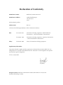
Declaration of Conformity
Manufacturer's Name:
RAD Data Communications Ltd.
Manufacturer's Address:
24 Raoul Wallenberg St.
Tel Aviv 69719
Israel
declares that the product:
RIC-155
Product Name:
conforms to the following standard(s) or other normative document(s):
EMC:
Safety:
EN 55022:1998
Information technology equipment – Radio disturbance
characteristics – Limits and methods of measurement.
EN 50024: 1998
Information technology equipment – Immunity characteristics
– Limits and methods of measurement.
EN 60950: 2000
Safety of information technology equipment.
Supplementary Information:
The product herewith complies with the requirements of the EMC Directive 89/336/EEC, the Low
Voltage Directive 73/23/EEC and the R&TTE Directive 1999/5/EC for wired equipment. The product
was tested in a typical configuration.
Tel Aviv, 10 July 2004
Haim Karshen
VP Quality
European Contact: RAD Data Communications GmbH, Otto-Hahn-Str. 28-30, 85521
Ottobrunn-Riemerling, Germany
Quick Start Guide
Installation of RIC-155 should be carried out only by an experienced technician. If
you are familiar with RIC-155, use this guide to prepare the units for operation.
1.
Installing RIC-155
Connecting the Interfaces
1. Connect the STM-1/OC-3c equipment to the fiber optic or BNC rear panel
connectors.
2. Connect the 10/100BT LAN to the DATA rear panel connector.
3. Use a cross cable to connect the control terminal to the rear panel CONTROL
connector.
or
Connect a Telnet host, a PC running a Web browsing application or a
RADview management station to the MNG port.
Connecting the Power
•
Connect the power cable to the power connector on the RIC-155 rear panel.
The unit has no power switch. Operation starts when the power is applied
to the rear panel power connector(s).
2.
Configuring RIC-155
Configure RIC-155 to the desired operation mode via an ASCII terminal connected to
the rear panel CONTROL port. Alternatively, you can manage RIC-155 over Telnet, a
PC running a Web browsing application or RADview application via the MNG port.
Starting Terminal Session for a First Time
To start a terminal session:
1. Connect a terminal cross-cable to the CONTROL connector of RIC-155.
2. Start a terminal application and configure the terminal link as follows:
Terminal emulation – VT100
Screen width – more than 80 characters.
3. Power RIC-155 up.
The SIG LED (green) blinks during software extraction and hardware
initialization.
Configuring RIC-155
1
RIC-155 Installation and Operation Manual
Quick Start Guide
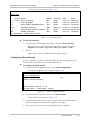
4. When the ALM LED (red) starts blinking, press <Enter> several times.
RIC-155 automatically adjusts itself to the current terminal baud rate and
responds with a string of dots.
5. Type several dots.
When the hardware initialization is completed, the SIG and ALM LEDs
flash rapidly six times.
6. Press <Enter> to display the user name and password entry form.
7. Enter your user name and password and proceed with the management
session.
Note
The RIC-155 default user names are SU and USER, default password is 1234.
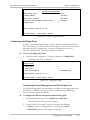
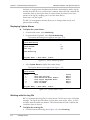
Configuring RIC-155
The management software provides a Quick Setup menu, which includes the most
basic parameters necessary for configuration.
To configure RIC-155:
•
From the Quick Setup menu (Main > Configuration > Quick Setup),
configure the following parameters:
Master Clock
Host IP address
Host IP mask
Default Gateway
Host Tagging
Host VLAN ID
Host VLAN Priority
Forwarding Mode
Physical Port Management Access
SDH/SONET frame type.
2
Configuring RIC-155
Contents
Chapter 1. Introduction
1.1 Overview..................................................................................................................... 1-1
Versions................................................................................................................................ 1-1
Application ........................................................................................................................... 1-1
Features................................................................................................................................ 1-2
1.2 Physical Description..................................................................................................... 1-4
1.3 Functional Description................................................................................................. 1-5
1.4 Technical Specifications............................................................................................... 1-6
Chapter 2. Installation and Setup
2.1
2.2
2.3
2.4
Introduction................................................................................................................. 2-1
Site Requirements and Prerequisites ............................................................................ 2-1
Package Contents ........................................................................................................ 2-2
Connecting the Interface Cables .................................................................................. 2-2
Connecting the STM-1/OC-3c Interface ................................................................................ 2-2
Connecting the 10/100BaseT Interface.................................................................................. 2-2
2.5 Connecting the Power Cable ....................................................................................... 2-3
Connecting AC Power........................................................................................................... 2-3
Connecting DC Power .......................................................................................................... 2-3
Chapter 3. Operation
3.1
3.2
3.3
3.4
Turning On RIC-155 .................................................................................................... 3-1
Controls and Indicators ................................................................................................ 3-1
Default Settings............................................................................................................ 3-3
Configuration Alternatives............................................................................................ 3-4
Managing RIC-155 via Terminal Port..................................................................................... 3-4
Managing RIC-155 via Ethernet Ports .................................................................................... 3-5
3.5 Navigating the Management Menus............................................................................. 3-7
Menu Map ........................................................................................................................... 3-7
Loging on ............................................................................................................................. 3-7
Choosing Options ................................................................................................................. 3-8
Correcting Entries ................................................................................................................. 3-8
Navigating Tables.................................................................................................................. 3-9
Logging Out.......................................................................................................................... 3-9
3.6 Turning Off RIC-155.................................................................................................... 3-9
Chapter 4. Configuration
4.1 Configuring RIC-155 for Management ......................................................................... 4-1
Entering Device Information.................................................................................................. 4-2
Configuring the Host Parameters ........................................................................................... 4-3
Configuring the Network Managers ....................................................................................... 4-4
Controlling the Management Access...................................................................................... 4-5
4.2 Configuring the RIC-155 for Operation ........................................................................ 4-6
Configuring the Clock Source................................................................................................ 4-7
Configuring Control Port Parameters ..................................................................................... 4-7
RIC-155 Installation and Operation Manual
i
Table of Contents
Enabling and Disabling Pop-up Alarms .................................................................................. 4-8
4.3 Configuring the Physical Ports ...................................................................................... 4-9
Configuring the Ethernet Interface......................................................................................... 4-9
Configuring the STM-1/OC-3c Interface ................................................................................ 4-9
4.4 Configuring the Internal Bridge .................................................................................. 4-12
Configuring Fast Ethernet Bridge ......................................................................................... 4-12
Configuring the Bridge Ports................................................................................................ 4-13
4.5 Displaying the RIC-155 Status.................................................................................... 4-15
Displaying the System Status ...............................................................................................4-15
Displaying the Port Status....................................................................................................4-16
4.6 Additional Tasks......................................................................................................... 4-18
Changing the Password ....................................................................................................... 4-18
Displaying the RIC-155 Inventory........................................................................................4-19
Installing Software Releases ................................................................................................. 4-20
Transferring Configuration Files ........................................................................................... 4-22
Displaying the Software Version .......................................................................................... 4-22
Switching Software Versions................................................................................................ 4-23
Resetting RIC-155............................................................................................................... 4-23
Chapter 5. Troubleshooting and Diagnostics
5.1 Monitoring Performance .............................................................................................. 5-1
Displaying the Ethernet Statistics ........................................................................................... 5-1
Displaying SDH/SONET Statistics .......................................................................................... 5-2
5.2 Detecting Errors ........................................................................................................... 5-7
Power-Up Self-Test ............................................................................................................... 5-7
Front Panel LEDs .................................................................................................................. 5-7
5.3 Handling Alarms .......................................................................................................... 5-7
Displaying System Alarms...................................................................................................... 5-8
Working with the Log File ..................................................................................................... 5-8
Configuring Alarm Severity.................................................................................................... 5-9
Masking Port Alarms ........................................................................................................... 5-10
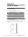
Appendix A. Connector Wiring
Appendix B. Traffic Separation
ii
RIC-155 Installation and Operation Manual
Chapter 1
Introduction
1.1 Overview
RIC-155 is a converter that enables simple and efficient connection of Fast
Ethernet traffic over STM-1/OC-3c lines. Equipped with a 10/100BaseT and fiber
optic or coaxial STM-1 interface, RIC-155 serves as cost-effective alternative to
ATM devices and routers. The RIC-155’s packet-over-SONET encapsulation
protocol enables virtually total utilization of SDH/SONET payload traffic, since only
a small header is required. RIC-155 supports VLAN bridging, flow control and
backpressure, according to IEEE 802.3x requirements.
Versions
STM-1/OC-3c Interface Options
•
Fiber optic interface
•
Electrical interface.
Power Supply Options
The following power supply versions are available:
•
100–240 VAC
•
24 VDC or -48 VDC.
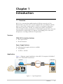
Application
Figure 1-1 illustrates a typical application, where RIC-155 transports 10/100BaseT
traffic over SDH/SONET infrastructure.
Central Site
Remote Site
RIC-155
RIC-155
Fiber or coax
Fiber or coax
SDH/SONET
STM-1/OC-3c
Data
Management
STM-1/OC-3c
ADM
ADM
IP
Network
Gigabit Ethernet
Switch/Router
Network
Management
Station
Gigabit Ethernet
Switch/Router
Figure 1-1. Typical Application
Overview
1-1
RIC-155 Installation and Operation Manual
Chapter 1 Introduction
Features
10/100BaseT Interface
RIC-155 Fast Ethernet interface operation conforms to the IEEE 802.3u, 802.3x
and 802.1p standards, including VLAN applications. The Fast Ethernet interface
supports the following functions:
•
Four levels of QoS, according to ToS or 802.3p
•
High performance lookup engine with support for up to 1024 MAC address
entries with automatic learning and aging
•
Autonegotiation
•
Backpressure
•
Half duplex and full duplex operation
•
FDX flow control
•
Automatic MDI/MDIX crossover.
STM-1/OC-3c Interface
RIC-155 converts Ethernet/Fast Ethernet signals into POS and vice. The
STM-1/OC-3c interface terminates into fiber optic or 75Ω BNC coaxial
connectors. Single mode fiber optic interface of the unit uses a 1310 nm LED or
1310/1550 laser diode transmitters (see Table 1-1).
The STM-1/OC-3c interface of RIC-155 operates with internal or receive clock.
Table 1-1. Fiber Optic Interface Options
Wavelength Fiber Type
Transmitter
Type
Power
Receiver
Sensitivity
Typical Max.
Range
[dBm]
[dBm]
[km/miles]
Connector
[nm]
[µm]
1310
62.5/125,
multimode
LED
-18
-31
2/1.2
SC
1310
9/125 single mode
Laser
-12
-31
20/12.4
ST, SC, FC
1310
9/125 single mode
Laser, long haul
-2
-34
40/25
ST, SC, FC
1550
9/125 single mode
Laser, long haul
-2
-34
80/49.7
SC
SF1 (WDM)
9/125 single mode Laser
Tx – 1310
Rx – 1550
9/125 single mode Laser
Tx – 1550
Rx – 1310
9/125 single mode Laser, 1310
Tx and Rx
-12
-29
20/12.4
SC
-12
-29
20/12.4
SC
-12
-27
20/12.4
SC/APC
SF2 (WDM)
SF3
(single fiber)
1-2
Overview
RIC-155 Installation and Operation Manual
Chapter 1 Introduction
Management
Setup, control and monitoring of status and diagnostics information can be
performed using one of the following methods:
• ASCII terminal connected to the V.24/RS-232 DTE control port
•
Telnet host via dedicated Ethernet management port
•
PC running a Web browsing application (ConfiguRAD)
•
Network management station running RADview, RAD’s SNMP network
management application.
ConfiguRAD is user-friendly Web-based terminal management system serving for
remote device configuration and maintenance. It is embedded in RIC-155 and
provided at no extra cost. ConfiguRAD can be run from any standard Web
browser.
Internal Bridge
The RIC-155 internal bridge uses four ports for connection to the Ethernet
management port, Ethernet data port, STM-1/OC-3c interface and the host. The
bridge provides separation of the management traffic from the user traffic by
assigning different VLANs to the different ports.
The bridge operates in the following modes:
•
Filter – frames are received with VLAN tag or untagged, the bridge learns the
source address of the incoming frames, performs the bridging according to the
MAC address only.
•
Filter Tagging – the bridge separates management traffic from the user traffic
by the tags assigned to the frames. The bridge operation complies with the
relevant parts of IEEE 802.1Q.
Alarm Relay
Real time alarms provide information on the system status, indicating management
failure, status of the STM-1/OC-3c and Ethernet links, and other faulty conditions.
Major and minor alarms can be reported to a remote alarm device via dedicated
DB-9 rear panel connector.
Alarms severity can be configured by the user. In addition, the RIC-155 alarms can
be masked to prevent them from being reported.
Status Reporting
RIC-155 includes LED indicators that display the status of power, fiber optic signal,
and Ethernet traffic.
RIC-155 supports Ethernet and STM-1/OC-3c statistics collection for up 96
15-minute intervals.
Overview
1-3
RIC-155 Installation and Operation Manual
Chapter 1 Introduction
1.2 Physical Description
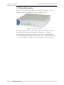
RIC-155 is a non-modular standalone unit, intended for tabletop or 19” rack
installation. Figure 1-2 illustrates a 3D view of the RIC-155 unit.
Figure 1-2. RIC-155 3D View
The front panel includes seven LEDs, which display the status of power, alarm,
10/100BaseT traffic and fiber optic signal. For details, refer to Chapter 3.
The back panel includes a power connector (AC or DC), a 10/100BaseT port
connectors (primary and management), and STM-1/OC-3c connector (fiber optic
or coaxial). The RIC-155 rear panel is described in greater detail, in Chapter 2.
1-4
Physical Description
RIC-155 Installation and Operation Manual
Chapter 1 Introduction
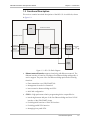
1.3 Functional Description
This section contains functional descriptions of the RIC-155 circuit blocks, shown
in Figure 1-3.
Main Card
CPU
Parallel CPU Interface
MDIO/MDC Interface
Management
Ethernet
Network
Ethernet
Network
Interface
Forward MII
CPLD
POS Level 2t
Interface
Fiber Optic/
Electrical
Interlace
SDH/SONET
Framer
SDH/SONET
Link
Power
Supply
Figure 1-3. RIC-155 Block Diagram
•
Ethernet network interface supports interfacing with Ethernet network. The
Ethernet interface is based on a multiport Fast Ethernet bridge with quality of
service support. The ports of the Fast Ethernet bridge perform the following
functions:
Data transmission over SDH/SONET link
Management from the local terminal
Interconnection between bridge and CPU
MAC MII configuration.
•
CPLD is a high performance lattice programming device responsible for:
Interfacing between MII port of the Fast Ethernet bridge and Level 2 POS
interface of the SDH/SONET framer
Providing MUX functions of SNI CPU interface
Providing parallel CPU interface
Managing front panel LEDs.
Functional Description
1-5
RIC-155 Installation and Operation Manual
Chapter 1 Introduction
•
Fiber optic/electrical interface provides connection to the fiber optic or
coaxial cables.
•
CPU controls the RIC-155 operation. It includes a microprocessor, flash
memory, and SRAM.
•
Power supply provides 5V and +3.3V voltage to the RIC-155 internal
elements.
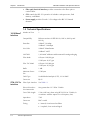
1.4 Technical Specifications
10/100BaseT
Interface
Number of Ports
1
Compatibility
Relevant sections of IEEE 802.3u, 802.3x, 802.1p and
802.3q
Data Rate
10BaseT: 10 Mbps
100BaseT: 100 Mbps
Line Code
10BaseT: Manchester
100BaseT: MLT3
LAN Table
1,024 MAC addresses with automatic learning and aging
Filter Mode
64 bytes: 148,810 pps
1518 bytes: 8,127 pps
Filter TAG Mode
64 bytes: 142,000 pps
1518 bytes: 8,110 pps
STM-1/OC-3c
Interface
Buffer
1 MB
Maximum Frame
Size
1536 bytes
Cable Type
Unshielded twisted pair (UTP), 19–26 AWG
Connector
RJ-45
Fiber Optic Interface
See Table 1-1
Electrical Interface
Line Attenuation
Not greater than 12.7 dB at 78 MHz
Coax Cable Length
135m (442 feet), when using RG-59 B/U (at 78 MHz, in
accordance with the square root of frequency law).
Impedance
75Ω
Connector
BNC coaxial
Timing
• Internal, from internal oscillator
• Loopback, from received signal
1-6
Technical Specifications
RIC-155 Installation and Operation Manual
Management V.24/RS-232
Monitoring
Chapter 1 Introduction
ASCII terminal via V.24/RS-232 serial DTE port
Ethernet
Telnet, Web browser or RADview via a MNG port
(out-of-band) or DATA port (inband)
STM-1/OC-3c
Optical input signal
Input signal monitoring based on received B2 error
counting
Frame signal
Alarm indication signal (AIS)
Remote detect indication (RDI)
10/100BaseT
Received valid frames
Transmitted valid frames
Alarm Relay
Indicators
Power
Physical
Alarm Types
Major and minor
Connector
DB-9, female
PWR (green)
Power
SPEED (green)
LAN speed
LINK/ACT (yellow)
Ethernet link integrity and activity
ALM (red)
Alarm
SIG (green)
Fiber optic or coaxial signal
AC Source
100 to 240 VAC (±10%), 50 to 60 Hz
DC Source
-48 VDC (±10%) or 24 VDC (±10%)
Power Consumption
8.8W
Height
43 mm / 1.7 in
Width
215 mm / 8.4 in
Depth
206 mm / 8.1 in
Weight
1.7 kg
Environment Temperature
Humidity
/ 3.7 lb
0–50°C / 32–122°F
Up to 90%, non–condensing
Technical Specifications
1-7
Chapter 1 Introduction
1-8
Technical Specifications
RIC-155 Installation and Operation Manual
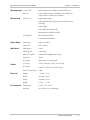
Chapter 2
Installation and Setup
2.1
Introduction
This chapter describes installation and setup procedures for the standalone
RIC-155 device.
After installing the unit:
• Refer to Chapter 3 for the operating instructions.
•
Refer to Chapter 4 for the detailed system configuration procedures using an
ASCII terminal connected to the RIC-155 control port.
If a problem is encountered, refer to Chapter 5 for test and diagnostic instructions.
The RIC-155 standalone unit is designed for desktop or bench installation and is
delivered as a fully assembled unit. No provisions are made for bolting the unit to
a tabletop.
Always observe standard safety precautions during installation, operation, and
maintenance of this product.
Warning
2.2
Site Requirements and Prerequisites
AC-powered RIC-155 units should be installed within 1.5m (5 ft) of an
easily-accessible grounded AC outlet capable of furnishing the voltage in
accordance with RIC-155 nominal supply voltage.
DC-powered RIC-155 unit requires a -48 VDC or 24 VDC power source, which
must be adequately isolated from the main supply.
Allow at least 90 cm (36 in) of frontal clearance for operating and maintenance
accessibility. Allow at least 10 cm (4 in) clearance at the rear of the unit for signal
lines and interface cables.
The ambient operating temperature of RIC-155 should be 0 to 50°C (32 to 122°F),
at a relative of up to 90%, non-condensing. humidity
Site Requirements and Prerequisites
2-1
RIC-155 Installation and Operation Manual
Chapter 2 Installation and Setup
2.3
Package Contents
The RIC-155 package includes the following items:
• One RIC-155 unit
•
Technical documentation CD
•
AC power cord or DC power supply connector kit
•
RM-35 rack mount kit (if ordered).
2.4
Connecting the Interface Cables
Figure 2-1 illustrates a typical rear panel of a RIC-155 unit.
10/100BaseT
SPEED LINK/ACT SPEED LINK/ACT
ALARM
SIG
CONTROL
MNG
TX
RX
DATA
Figure 2-1. RIC-155 Rear Panel
Connecting the STM-1/OC-3c Interface
The RIC-155 STM-1/OC-3c interface terminates in fiber optic or BNC coaxial
connectors, designated RX and TX.
To connect a fiber optic cable:
1. Remove the protective caps from the connectors and store them in a safe
place for later use.
2. Connect the transmit fiber to the connector marked TX and the receive fiber to
the connector marked RX.
3. At the remote unit connect the transmit fiber to the connector marked RX and
the receive fiber to the connector marked TX.
To connect a coaxial cable:
1. Connect the transmit cable to the connector marked TX and the receive fiber
to the connector marked RX.
2. At the remote unit connect the transmit cable to the connector marked RX and
the receive cable to the connector marked TX.
Connecting the 10/100BaseT Interface
The 10/100BaseT interface of RIC-155 terminates in RJ-45 connector designated
DATA.
To connect the 10/100BaseT interface:
•
2-2
Connect the LAN to the rear panel RJ-45 connector designated DATA.
Connecting the Interface Cables
RIC-155 Installation and Operation Manual
2.5
Chapter 2 Installation and Setup
Connecting the Power Cable
To connect RIC-155 to the power source, refer to the appropriate section below,
depending on your version of the unit (AC or DC).
Warning
Before switching on this unit and connecting or disconnecting any other cable,
the protective earth terminals of this unit must be connected to the protective
ground conductor of the mains (AC or DC) power cord. If you are using an
extension cord (power cable) make sure it is grounded as well.
Any interruption of the protective (grounding) conductor (inside or outside the
instrument) or disconnecting of the protective earth terminal can make this
unit dangerous. Intentional interruption is prohibited.
Connecting AC Power
AC power is supplied to the RIC-155 through a standard 3-prong plug
AC power should be supplied via a 1.5m (5 ft) standard power cable terminated
by a standard 3-prong socket. A cable is provided with the unit.
To connect AC power:
1. Connect the power cable to the power connector on the RIC-155 rear panel.
2. Connect the power cable to the mains outlet.
The unit will be turned on automatically upon connection to the mains.
Connecting DC Power
A special IEC 60320 adapter for -48/-60 VDC power connection is supplied with
the unit. 24 VDC RIC-155 units have a terminal block DC inlet and adapter
supplied with the unit.
To connect DC power:
•
Refer to the DC power supply connection supplements for instructions how to
wire the DC adapters, and to the Handling Energized Products section.
Connecting the Power Cable
2-3
Chapter 2 Installation and Setup
2-4
Connecting the Power Cable
RIC-155 Installation and Operation Manual
Chapter 3
Operation
This chapter provides the following information for the RIC-155 converter:
• RIC-155 indicators
•
Turning-on and turning-off the RIC-155
•
Default settings.
Installation procedures given in Chapter 2 must be completed and checked before
attempting to operate RIC-155.
3.1
Turning On RIC-155
To turn on RIC-155:
•
Connect the power cord to the mains.
The PWR indicator on the front panel lights up and remains on as long as
RIC-155 receives power.
RIC-155 requires no operator attention once installed, with the exception of
occasional monitoring of front panel indicators. Intervention is only required when
RIC-155 must be configured to its operational requirements.
3.2
Controls and Indicators
The front panel includes a series of LED indicators that show the current operating
status of the unit. Figure 3-1 illustrates front panel of the RIC-155 unit. Table 3-1
lists and describes the indicator functions.
RIC-155
10/100 BaseT
SPEED
PWR
SIG
LINK/ACT
ALM
MNG
DATA
155 Mbps
Figure 3-1. RIC-155 Front Panel
Controls and Indicators
3-1
RIC-155 Installation and Operation Manual
Chapter 3 Operation
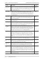
Table 3-1. RIC-155 LEDs
Name
Function
Location
PWR (green)
ON – Power supply is ON
Front panel
ALM (red)
ON – Alarm is present in the alarm buffer
Front panel
SPEED (green)
ON – LAN is operating at 100 Mbps
Front/rear panel
OFF – LAN is operating at 10 Mbps
ACT/LINK
(yellow)
ON – LAN is connected to the Ethernet interface
Front/rear panel
OFF – LAN is not connected to the Ethernet interface
Blinking – Ethernet interface is receiving/transmitting data
SIG (green)
ON – Link integrity signal is detected on the STM-1/OC-3 link
Front/rear panel
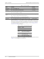
Upon turning RIC-155 on, the PWR LED in the front panel lights to indicate that
RIC-155 is on. Table 3-2 shows the correct status of the indicators after power-up
and software decompression. RIC-155 initialization may take up to 3.5 minutes.
For detailed description of the initialization sequence, refer to Starting Terminal
Session for a First Time in Chapter 4.
Table 3-2. RIC-155 Normal Indicator Status
Indicator
Status
PWR
ON
ALM
OFF, if all ports are connected
SPEED
ON or OFF, according to the
speed of connected LAN
LINK/ACT
Blinking, if port is connected
and transferring data
SIG
ON, if port is connected
If the above LED indications do not appear following initial power turn-on, refer to
Chapter 5 for the diagnostic test instructions.
3-2
Controls and Indicators
RIC-155 Installation and Operation Manual
3.3
Chapter 3 Operation
Default Settings
RIC-155 is managed by an ASCII terminal or PC running a terminal emulation
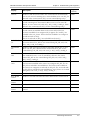
program via menu-driven embedded software. Table 3-3 lists the default settings of
the RIC-155 configuration parameters.
Table 3-3. RIC-155 Default Settings
Parameter
Default Value
System
Master clock
Lbt
Management
System Contact
The contact person
System Name
RIC-155
System Location
The location of this device
Host IP address
0.0.0.0
Host IP mask
0.0.0.0
Host default gateway
0.0.0.0
Read community
Public
Write community
Trap community
Telnet access
Enable
SNMP access
Enable
Web access
Enable
Web Trace Refresh
10
Physical port access
MNG ONLY
Control Port
Control port rate
9600 bps
POP alarm
OFF
Security timeout
10 min
DATA Port (Physical)
Autonegotiation
Enable
Flow control
Enable
Ethernet mode
Full duplex
LAN speed
100 Mbps
MNG Port (Physical)
Autonegotiation
Enable
Default Settings
3-3
RIC-155 Installation and Operation Manual
Chapter 3 Operation
Parameter
Default Value
Flow control
Enable
Ethernet mode
Full duplex
LAN speed
100 Mbps
Uplink
Frame type
SONET
BER threshold
Disable
EED threshold
10E-3
SD threshold
10E-6
J1 Tx path trace enable
Disable
J1 path trace
Physical Failure Forwarding
Disable
Bridge
Aging Time
304
Forwarding Mode
Filter
Statistics Counted
OK only
Multicast & Broadcast Rate
Limit
No Limit
DATA Port PVID
2
DATA Port PVID Priority
0
DATA Port Tag Stripping
No
MNG Port PVID
1
MNG Port PVID Priority
0
MNG Port Tag Stripping
No
POS Port Egress
Unmodified
3.4
Configuration Alternatives
Managing RIC-155 via Terminal Port
RIC-155 includes a V.24/RS-232 asynchronous DTE port, designated CONTROL
and terminated in a 9-pin D-type female connector. The control port continuously
monitors the incoming data stream and immediately responds to any input string
received through this port. The port requires a cross-cable for the ASCII terminal
connection.
The RIC-155 control port can be configured to communicate at the following
rates: 9.6, 19.2, 38.4, 57.6 or 115.2 kbps. When running a terminal control
3-4
Configuration Alternatives
RIC-155 Installation and Operation Manual
Chapter 3 Operation
session for the first time or after changing a terminal data rate, RIC-155 must
detect the data rate at boot-up and save it in the database. Once the terminal data
rate is saved, it is detected automatically during each consecutive terminal session.
Preparing the Terminal
Any standard ASCII terminal (a “dumb” terminal or a personal computer running
a terminal emulation application) equipped with a V.24/RS-232 communication
interface can be used to configure RIC-155. Appendix A details the pin assignment
and control signal directions of the RIC-155 control connector.
Starting Terminal Session for a First Time
To start a terminal session:
1. Connect a terminal cross-cable to the CONTROL connector of RIC-155.
2. Start a terminal application and configure the terminal link as follows:
Terminal emulation – VT100
Screen width – more than 80 characters.
3. Power RIC-155 up.
The SIG LED (green) blinks during software extraction and hardware
initialization.
4. When the ALM LED (red) starts blinking, press <Enter> several times.
RIC-155 automatically adjusts itself to the current terminal baud rate and
responds with a string of dots.
5. Type several dots.
When the hardware initialization is completed, the SIG and ALM LEDs
flash rapidly six times.
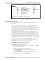
6. Press <Enter> to display the user name and password entry form.
7. Enter your user name and password and proceed with the management
session.
Note
The RIC-155 default user names are SU and USER, default password is 1234.
Managing RIC-155 via Ethernet Ports
RIC-155 is equipped with a management Ethernet port (MNG) which enables
communication with RIC-155 management subsystem using the IP protocol. The
Ethernet management port is configured for LAN cross-over connection.
To prepare RIC-155 for network management:
1. Connect a LAN network management station to the RIC-155 Ethernet port
designated MNG.
2. Configure IP host parameters of the RIC-155 units via an ASCII terminal.
3. Run an SNMP management application, such as RAD’s RADview-Lite, open
Telnet session, or manage RIC-155 via a Web browser (ConfiguRAD).
Configuration Alternatives
3-5
RIC-155 Installation and Operation Manual
Chapter 3 Operation
Cautions • Make sure the Ethernet management ports of the local and remote devices are
connected to different LANs.
• Do not run diagnostic loopbacks on RIC-155 or insert loopback plugs into its
Ethernet ports.
Notes
• When RIC-155 is managed over Telnet or ConfiguRAD, only two simultaneous
management sessions are allowed. An additional management session can be
opened from the supervisory terminal.
• If no user input is detected for 10 minutes during Telnet or ConfiguRAD session,
RIC-155 automatically disconnects from the management station.
• ConfiguRAD management utility is compatible with Internet Explorer 6.0 and
above.
To start a ConfiguRAD session:
1. Start a Web browser.
2. Disable any pop-up blocking software, such as Google Popup Blocker.
3. In the address bar, enter an IP address of RIC-155, and press <Enter>.
The Login screen appears.
4. In the Login screen, click Login to start the ConfiguRAD management session.
Note
3-6
Disable the proxy server connection for the Web browser to ensure stable
ConfiguRAD session.
Configuration Alternatives
RIC-155 Installation and Operation Manual
3.5
Chapter 3 Operation
Navigating the Management Menus
This section provides a general description of the software menu operation and
conventions for navigating the menus.
Menu Map
Figure 3-2 lists all RIC-155 menus.
Figure 3-2. Menu Map
Note
ConfiguRAD menus differ in appearance from the terminal screens, but have the
same functionality.
Loging on
Enter a user name and password in order to start the RIC-155 management
software.
To enter the user name and password:
1. Type in USER or SU and press <Enter>.
2. Type the password (Default 1234).
RIC-155 responds to your entry with asterisks.
Note
It is recommended to change the default password to prevent unauthorized access
to RIC-155.
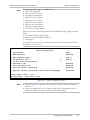
3. Press <Enter>.
The Main menu is displayed (see Figure 3-3).
Navigating the Management Menus
3-7
RIC-155 Installation and Operation Manual
Chapter 3 Operation
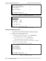
RIC-155
Main Menu
1. Inventory
2. Configuration
3. Monitoring
4. File Utilities
ESC-prev.menu; !-main menu; &-exit
Figure 3-3. Main Menu (Terminal Session)
ConfiguRAD provides auxiliary management tools in the lower left-hand corner:
•
Status – shows the number of users currently managing RIC-155
•
Trace – opens an additional pane for system messages, progress indicators
(ping, software and configuration file downloads) and alarms. It is
recommended to keep the trace pane open all the time. Refresh rate of the
Trace pane is user-configurable.
•
Refresh All – refreshes performance registers.
Choosing Options
To choose an option (terminal session):
•
Type the number corresponding to the option, and press <Enter>.
RIC-155 immediately updates its database with a new value or displays a
new menu for the selected option.
Note
When a menu option has only two values, typing the option number and pressing
<Enter> toggles between the available values.
To choose an option (ConfiguRAD session):
1. Click a link in the ConfiguRAD screen to display the next menu.
2. Once the target screen is displayed, select a value from the drop-down box or
enter it in a text box.
Correcting Entries
To correct an erroneous entry:
•
3-8
Press <Backspace> to clear the error, then enter the correct characters.
or
Press <Esc> to exit the current menu, and then return to the menu to
re-enter the required value.
Navigating the Management Menus
RIC-155 Installation and Operation Manual
Chapter 3 Operation
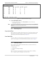
Navigating Tables
Some of the RIC-155 management software screens are tables, which are bigger
than regular menus and require scrolling to navigate between parameters. For
example, the Inventory screen or Manager List menu are considered tables.
Use the following keys (case-sensitive) for tables navigation:
Note
•
Ctrl L – scroll left,
Left Arrow – move left,
•
Ctrl R – scroll right,
Right Arrow – move right
•
Ctrl U – scroll up,
Up Arrow – move up
•
Ctrl D – scroll down, Down Arrow – move down
•
<Tab> – select next changeable cell
•
G<row number>, <col number> - go to cell.
You can display these navigation keys by typing <?> from a table.
Logging Out
To end the current session:
•
Note
In the Main menu, click Logout.
RIC-155 allows up to three management sessions to be active at a time. If a
Web-based management session was not ended properly, (for example, by closing
the Web browser window instead of logging out), you have to wait five minutes
before attempting the next log-in. If you try to log in during the five-minute security
timeout, RIC-155 does not allow you to proceed to the Main menu, displaying ‘Too
Many Users’ warning.
3.6
Turning Off RIC-155
To turn off RIC-155:
•
Remove the power cord from the power source.
Turning Off RIC-155
3-9
Chapter 3 Operation
3-10
Turning Off RIC-155
RIC-155 Installation and Operation Manual
Chapter 4
Configuration
4.1
Configuring RIC-155 for Management
Configuration of RIC-155 is performed via menu-driven embedded software, using
a standard ASCII terminal or PC running a terminal emulation application,
connected to the rear panel CONTROL port. Alternatively, you can manage
RIC-155 over Telnet, a PC running a Web browsing application such as
ConfiguRAD or the RADview-Lite application via the MNG port.This section
describes the configuration procedures for the RIC-155 converter.
To access the Configuration menu:
•
From the Main menu, select Configuration.
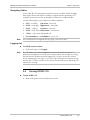
The Configuration menu appears (see Figure 4-1).
RIC-155
Configuration
1. Quick Setup
2. System Configuration
3. Physical Ports Configuration
4. Bridge Configuration
>
>
>
>
>
Please select item <1 to 4>
ESC-prev.menu; !-main menu; &-exit
Figure 4-1. Configuration Menu
Note
The Quick Setup menu is described in the Quick Start Guide.
Define the RIC-155 internal SNMP agent parameters in order to enable SNMP,
Telnet or Web-based management (see Figure 4-2). Also you can enter additional
information about your RIC-155, such as contact person, unit location etc.
To access the Management menu:
•
Follow the path: Configuration > System Configuration >Management.
The Management menu appears (see Figure 4-2).
Configuring RIC-155 for Management
4-1
RIC-155 Installation and Operation Manual
Chapter 4 Configuration
RIC-155
Management
1. Device Info
2. Host IP
3. Manager List
4. Management Access
>
>
>
>
>
Please select item <1 to 4>
ESC-prev.menu; !-main menu; &-exit
Figure 4-2. Management Menu
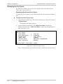
Entering Device Information
The Device Info menu allows you to assign a name to RIC-155, give description for
the unit, define its location, and contact person. These entries may include up to
20 characters.
To enter device information:
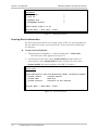
1. Follow the path: Configuration > System Configuration > Device Info.
The Device Info menu appears (see Figure 4-3).
2. From the Device Info menu, select System Contact and enter name of a
contact person; select System Name and enter a name of the unit; select
System Location and enter description of the RIC-155 location.
RIC-155
Device Info
System description (RIC-155 HW Version:xxxxx SW Version:xxxxx)
1. System contact
(Contact Person)
2. System name
(RIC-155)
3. System location
(Location of this device)
>
ESC-prev.menu; !-main menu; &-exit
Figure 4-3. Device Info Menu
4-2
Configuring RIC-155 for Management
RIC-155 Installation and Operation Manual
Chapter 4 Configuration
Configuring the Host Parameters
RIC-155 can be managed by a network management station, which is located on
the LAN connected to the unit’s MNG port. In order to establish a proper
connection, it is necessary to configure the following: host IP address, subnet
mask, default gateway, its trap, read and write communities.
Note
The following parameters are masked during Telnet, ConfigureRAD, RADview
sessions:
• Host IP address
• Host IP mask
• Host default gateway
• Host Tagging
• VLAN ID
• Host VLAN priority.
They can be configured from a supervisory terminal only.
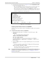
To define the IP parameters:
1. Follow the path: Configuration > System Configuration > Management >
Host IP.
The Host IP menu appears (see Figure 4-4).
2. From the Host IP menu, perform the following:
Select Host IP List to define the host IP address and IP mask in the Host IP
List menu (see Figure 4-5).
Select Host Default Gateway to set the default gateway IP address.
Select Read Community to enter the name of a community with read-only
authorization.
Select Write Community to enter the name of a community with write
authorization.
Select Trap Community to enter the name of a community to which
RIC-155 sends traps.
Select Host Tagging and set it to Tagged or Untagged to enable or disable
VLAN tagging performed by the host.
If the host tagging is enabled, select VLAN ID to enter the ID of the host
VLAN (0–4094).
If the host tagging is enabled, select Host VLAN priority to specify priority
of the host VLAN (0–7).
Note
Host IP addresses of both RIC-155 (local and remote) should be set to the same
subnet.
Configuring RIC-155 for Management
4-3
RIC-155 Installation and Operation Manual
Chapter 4 Configuration
RIC-155
Host IP
1. Host IP List
2. Host default gateway
3. Read community
4. Write community
5. Trap community
6. Host Tagging
7. VLAN ID [1-4094]
8. Host VLAN priority
>
>
(0.0.0.0)
(public)
(public)
(public)
(Tagged)
(1)
(1)
ESC-prev.menu; !-main menu; &-exit
Figure 4-4. Host IP Menu
RIC-155
Host IP List
1. IP Address
2. IP Mask
(0.0.0.0)
(0.0.0.0)>
ESC-prev.menu; !-main menu; &-exit
Figure 4-5. Host IP List Menu
Configuring the Network Managers
Define or modify the network management stations to which the SNMP agent of
RIC-155 sends traps. Up to ten managers can be defined. Entering the IP address
and corresponding subnet mask defines each management station. In addition,
you can temporarily prevent a manager station from receiving traps by masking
them.
To configure the network managers:
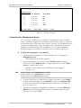
1. Follow the path: Configuration > System Configuration > Management >
Manager List.
The Manager List menu appears (see Figure 4-6).
2. From the Manager List menu, select a management station by moving the
cursor up/down or left/right.
3. Enter a new IP address for the selected management station.
4. Move to the Trap Mask field and toggle between YES and NO to mask or
unmask traps for the selected management station.
5. Repeat step 2 and step 3 to define additional management stations.
4-4
Configuring RIC-155 for Management
RIC-155 Installation and Operation Manual
Chapter 4 Configuration
RIC-155
Manager List
Manager ID
1.
IP address
0.0.0.0
Trap Mask
NO
2.
0.0.0.0
NO
3.
0.0.0.0
NO
4.
0.0.0.0
NO
5.
0.0.0.0
YES
ESC-prev.menu; !-main menu; &-exit; ?-help
Figure 4-6. Manager List Menu
Controlling the Management Access
You can enable or disable access to the RIC-155 management system via SNMP,
Telnet or Web-based applications. By disabling SNMP, Telnet or Web, you prevent
unauthorized access to the system when security of the RIC-155 IP address has been
compromised. When SNMP, Telnet and Web access is disabled, RIC-155 can be
managed via an ASCII terminal only. In addition, you can enable or disable an
inband management (via uplink or DATA port) or out-of-band (via MNG port).
To define the management access method:
1. Follow the path: Configuration > System Configuration > Management >
Management Access.
The Management Access menu appears.
2. From the Management Access menu, select TELNET Access to configure
Telnet access, select SNMP Access to configure SNMP access, or select WEB
Access to configure Web access.
A TELNET Access, SNMP Access or WEB Access menu appears
(see Figure 4-7).
Note
During a Telnet session, Telnet Access is masked.
During a SNMP session, SNMP Access is masked.
During a Web session, Web Access is masked.
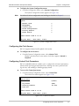
3. From the TELNET Access, SNMP Access or WEB Access menu, select ENABLE
to allow selected management type, DISABLE to restrict it, or Managers Only
to allow access only for the management stations defined in the Manager List
menu (see Figure 4-6).
4. If the Web management (ConfiguRAD) is enabled, you can select WEB Trace
Refresh from the Management Access menu, and define refresh rate of the
Trace pane in seconds (1–255).
Configuring RIC-155 for Management
4-5
RIC-155 Installation and Operation Manual
Chapter 4 Configuration
RIC-155
TELNET Access (Enable)
1. Enable
2. Disable
3. Managers only
Please select item <1 to 3>
ESC-prev.menu; !-main menu; &-exit
Figure 4-7. TELNET Access Menu
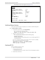
To enable or disable management ports:
1. From the Management Access menu, select Physical Ports Access.
The Physical Ports Access menu appears (see Figure 4-8).
2. From the Physical Ports Access menu, select None to disable both inband and
out-of-band management, MNG only to enable out-of-band management only
(via MNG port), or All to enable management via Ethernet management and
data ports.
Appendix B illustrates connections between the management port, data port,
STM-1/OC-3c port and the CPU within internal bridge.
Note
Whenever the Physical Ports Access mode is changed, the POS Port Egress
(STM-1/OC-3c) and Tag Stripping (data and management Ethernet ports) are set to
their default values as explained in Appendix B.
RIC-155
Physical Ports Access (All)
1. None
2. MNG only
3. All
Please select item <1 to 3>
ESC-prev.menu; !-main menu; &-exit
Figure 4-8. Physical Ports Access Menu
4.2
Configuring the RIC-155 for Operation
The RIC-155 management software allows you to perform the following:
• Setting source clock
4-6
•
Defining control port parameters
•
Defining alarm severity and masking alarms
•
Resetting RIC-155 to the default values
•
Performing the overall reset of the device.
Configuring the RIC-155 for Operation
RIC-155 Installation and Operation Manual
Chapter 4 Configuration
To display the System Configuration menu:
•
Note
From the Configuration menu, select System Configuration.
The System Configuration menu appears (see Figure 4-9).
Procedures for alarm configuration and masking are detailed in Chapter 5.
RIC-155
System
1. Master clock
2. Management
3. Control port
4. Alarm Configuration
5. Factory default
6. Reset Device
>
Please select item <1 to 5>
>
>
>
>
>
>
ESC-prev.menu; !-main menu; &-exit
Figure 4-9. System Configuration Menu
Configuring the Clock Source
RIC-155 supports internal and loopback clock modes.
To configure the clock source:
•
From the System Configuration menu, select Master Clock.
Display is refreshed and a new master clock value appears: Internal or
Loopback.
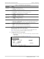
Configuring Control Port Parameters
RIC-155 embedded software enables you to configure the serial port parameters,
which include specifying terminal baud rate, defining user name, password and
log-off time, and enabling or disabling pop-up alarms.
To access the Control port menu:
•
From the System Configuration menu, select Control Port.
The Control Port menu appears (see Figure 4-10).
RIC-155
Control Port
1. Baud Rate
2. Pop Alarm
3. Security Timeout
4. Save All
>(9600)
(OFF)
(10 min)
>
Please select item <1 to 4>
ESC-prev.menu; !-main menu; &-exit
Figure 4-10. Control Port Menu
Configuring the RIC-155 for Operation
4-7
RIC-155 Installation and Operation Manual
Chapter 4 Configuration
Changing the Control Port Data Rate
To configure the control port data rate:
1. From the Control Port menu, select Baud Rate.
The Baud Rate menu appears (see Figure 4-11).
2. Select the terminal rate by typing the number corresponding to the desired
value, and pressing <Enter>.
3. From the Control Port menu, select Save All to save the new baud rate.
RIC-155
Baud Rate (9600)
1. 9600 bps
2. 19200 bps
3. 38400 bps
4. 57600 bps
5. 115200 bps
Please select item <1 to 5>
ESC-prev.menu; !-main menu; &-exit
Figure 4-11. Baud Rate Menu
Configuring the Security Timeout
The timeout specifies a time interval after which RIC-155 automatically
disconnects from the supervisory terminal if no input from the user is detected.
The timeout can be set to 10 minutes or disabled.
To configure the security timeout:
•
From the Control Port menu, select Security Timeout to disable it (OFF) or set
to 10 minutes (10min).
The display is refreshed and a new value appears.
Note
Security timeout value is not valid for the Telnet or ConfiguRAD management,
which are permanently set to 10 minutes.
Enabling and Disabling Pop-up Alarms
When the pop-up function is enabled, RIC-155 displays alarms as they are
generated by the system or received by the interfaces. The alarms are displayed at
the bottom of the terminal screen.
To enable or disable pop-up alarms:
•
From the Control Port menu, select Pop Alarm to choose the pop-up alarms
mode: ON (pop-up alarms are enabled) or OFF (pop-up alarms are disabled).
The display is refreshed and a new value appears.
4-8
Configuring the RIC-155 for Operation
RIC-155 Installation and Operation Manual
4.3
Chapter 4 Configuration
Configuring the Physical Ports
Physical ports of RIC-155 include the following configurable subsystems:
•
Data 10/100BaseT port
•
Management 10/100BaseT port
•
STM-1/OC-3c port.
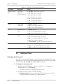
Configuring the Ethernet Interface
To configure the Ethernet interface:
1. Follow the path: Physical Ports Configuration > Ethernet Configuration >
DATA Port or MNG Port.
DATA Port or MNG Port menu appears (see Figure 4-12).
2. From the DATA Port or MNG Port menu, configure the following parameters:
Autonegotiation (Enable or Disable)
Flow Control (Enable or Disable)
Ethernet Mode (Full Duplex or Half Duplex)
LAN Speed (10 Mbps or 100 Mbps).
RIC-155
DATA Port
1. Auto-negotiation:
2. Flow Control:
3. Ethernet Mode:
4. LAN Speed: (100 Mbps)
(Disable)
(Enable)
(Full Duplex)
Please select item <1 to 4>
ESC-prev.menu; !-main menu; &-exit
Figure 4-12. DATA Port Menu
Note
If autonegotiation is enabled, the Ethernet Mode and LAN speed options are masked.
Configuring the STM-1/OC-3c Interface
The STM-1/OC-3c interface of RIC-155 is based on the SDH/SONET framer that
implements mapping functions of a channel for SDH/SONET processing at
155.52 Mbps.
To configure STM-1/OC-3c interface:
1. Follow the path: Configuration > Physical Ports Configuration > Uplink
Configuration.
The Uplink Configuration menu appears (see Figure 4-13).
2. From the Uplink Configuration menu, configure the following parameters
Configuring the Physical Ports
4-9
RIC-155 Installation and Operation Manual
Chapter 4 Configuration
Uplink Mode, uplink operation mode
SDH
SONET
BER Threshold, controls activation of the Line BER SD and EED
Enable, the EED and SD statistics data is collected
Disable, the EED and SD statistics data is not collected
EED Threshold, Excessive Error Defect threshold in 1E-N, where N = 3, 4
or 5. The Excessive Error Defect is detected if an equivalent BER exceeds
selected EED threshold. The Excessive Error Defect is cleared if the
equivalent BER is better then 1E-(EED + 1).
10E-3, 10E-4, 10E-5
SD Threshold, Degraded Signal Defect threshold in 1E-N, where N = 5, 6,
7, 8 or 9. The Degraded Signal Defect is detected if an equivalent BER
exceeds selected SD threshold. The Degraded Signal Defect is cleared if the
equivalent BER is better then 1E-(SD + 1).
10E-5, 10E-6, 10E-7, 10E-8, 10E-9
J1 Path Trace Configuration controls the insertion of a user-defined test
string (trace) into the transmit path (J1 byte). A second menu opens to
define the following:
Enable/Disable, transmit path trace insertion is enabled or disabled
Actual Rx Path Trace, specifies the format of the path trace (up to 62
characters for SONET and up to 15 characters for SDH)
Tx Path Trace, transmit test string
Rx Path Trace, receive test string
Padding, select spaces or nulls.
Note
Both sites must be configured the in the same manner.
J1 Path Trace.
Physical Failure Forwarding specifies whether the Ethernet traffic is
interrupted if an STM-1/OC-3c uplink failure is detected.
Enable the Ethernet traffic is interrupted if an STM-1/OC-3c uplink
failure is detected
Disable the Ethernet traffic is not interrupted if an STM-1/OC-3c uplink
failure is detected.
4-10
Configuring the Physical Ports
RIC-155 Installation and Operation Manual
Note
Chapter 4 Configuration
The following alarms trigger an uplink failure:
• Uplink Port Signal Loss
• Line Excessive Error Defect
• Line Signal Degraded Error
• Uplink Port Loss of Signal
• Uplink Port Loss of Frame
• Path Rx Facility Pointer Loss
• Path Excessive Error Defect
• Path Signal Degraded Error
• Path Trace J1 string mismatch.
With Physical Failure Forwarding enabled, three additional alarms trigger an uplink
failure:
• Line Alarm Indication Signal (AIS-L)
• Remote Line Defect Indication (RDI-L)
• Unequipped.
It is possible to mask errors in the Alarm Setup menu, so that the uplink will not be
interrupted. (See Chapter 5)
RIC-155
Uplink Configuration
1.
2.
3.
4.
5.
6.
7.
8.
8.
Uplink Mode:
BER Threshold:
EED Threshold (10E-):
>
SD Threshold (10E-):
>
J1 Path Trace Configuration:
>
Send AIS-L (K2)...
Send Unequipped (C2)
Physical failure forwarding
Physical failure forwarding on RDI-L/AIS-L/Unequipped
(SDH)
(Enabled)
(10E-3)
(10E-6)
(Enabled)
(Enabled)
(Enabled)
(Disabled)
Please select item <1 to 8>
ESC-prev.menu; !-main menu; &-exit
Figure 4-13. Uplink Configuration Menu
Note
• Item 9 of Figure 4-13, appears only when item 8, Physical failure forwarding, is
enabled.
• If item 9 is enabled, RIC-155 considers the RDI-L/AIS-L/Unequipped status in
addition to all the other alarms in physical failure forwarding.
Configuring the Physical Ports
4-11
RIC-155 Installation and Operation Manual
Chapter 4 Configuration
4.4
Configuring the Internal Bridge
Configuring Fast Ethernet Bridge
RIC-155 includes a high-performance Fast Ethernet QoS bridge with VLAN tagging
capabilities, MDI/MDIX automatic crossover and FDX flow control. Each port
works at 10 Mbps or 100 Mbps, full duplex or half duplex mode (forced or
autonegotiated).
To configure the Fast Ethernet bridge:
1. From the Configuration menu, select Bridge Configuration.
The Bridge Configuration menu appears (see Figure 4-14).
2. From the Bridge Configuration menu, configure the following parameters:
Aging Time (a period of time from the moment when a node is
disconnected from the network segment or becomes inactive and removal
of the node address from the database.)
0 to 4080 seconds in 16 second increments
Note
If aging time is set to 0 and address buffer has reached its maximum capability
(1024 addresses) it stops storing new addresses.
Forwarding Mode (operation mode of the internal bridge)
Filter (frames are received with VLAN tag or untagged, the bridge learns
the source address of the incoming frames, performs the bridging
according to the MAC address only)
Filter Tagged (The bridge separates management traffic from the user
traffic by the tags assigned to the frames. The switch operation complies
with the relevant parts of IEEE 802.1Q.)
Note
Whenever the Forwarding Mode is changed, the POS Port Egress (STM-1/OC3) and
Tag Stripping (data and management Ethernet ports) are set to their default values
and explained in Appendix B.
Statistics Counted (statistics collection mode)
OK only (RIC-155 counts the number of received good frames and the
number of transmitted frames)
Failed only (RIC-155 counts the number of received bad frames with
the number of encountered collisions)
Multicast & Broadcast Rate Limit (controls the traffic volume coming into
the internal bridge): 128 kbps, 256 kbps, 512 kbps, 1 Mbps, 2 Mbps,
4 Mbps, 8 Mbps, No Limit.
4-12
Configuring the Internal Bridge
RIC-155 Installation and Operation Manual
Chapter 4 Configuration
RIC-155
Bridge Configuration
Aging Time (sec)
Bridging Mode
Statistics Counted
Multicast and Broadcast Rate Limit
Bridge Ports
(314)
(Filter)
(OK only)
> (8 Mbps)
>
Please select item <1 to 5>
ESC-prev.menu; !-main menu; &-exit
Figure 4-14. Bridge Configuration Menu
Configuring the Bridge Ports
The RIC-155 internal bridge includes four ports: Ethernet management, Ethernet
data, POS (STM-1/OC-3c link) and host. The bridge ports can be used for isolating
management traffic from data traffic, serving as an important security tool.
Appendix B details the RIC-155 traffic separation mechanism.
To access the Bridge Port menu:
•
Follow the path: Configuration > Bridge Configuration > Bridge Ports.
The Bridge Ports menu is displayed.
RIC-155
Bridge Ports
1. DATA Port
2. MNG Port
3. POS Port Egress
>
>
> (Unmodified)
Please select item <1 to 3>
ESC-prev.menu; !-main menu; &-exit
Figure 4-15. Bridge Ports Menu
Configuring Ethernet Management and Data Bridge Ports
The Ethernet management and data bridge ports support VLAN tagging and VLAN
prioritization. In addition, these ports can be configured to strip VLAN tags at
egress or leave the frames unmodified.
To configure the Ethernet management and data bridge ports:
1. From the Bridge Ports menu, select DATA Port or MNG Port.
The DATA Port or MNG Port menu appears.
2. From the DATA Port or MNG Port menu, configure the following:
PVID (ID of the VLAN assigned to the current port): 1–4094.
PVID Priority (priority of the assigned VLAN): 0–7
Configuring the Internal Bridge
4-13
RIC-155 Installation and Operation Manual
Chapter 4 Configuration
Tag Stripping (specifies whether the port strips the VLAN tags at egress or
not)
Enable (the tags are stripped)
Disable (the frames are left unchanged).
Note
Whenever the Physical Ports Access mode is changed, Tag Stripping is set to its
default value, as explained in Appendix B.
RIC-155
DATA Port
1. PVID [1 – 4094]
2. PVID priority
3. Tag Stripping
<2>
<2>
<No>
Please select item <1 to 3>
ESC-prev.menu; !-main menu; &-exit
Figure 4-16. DATA Port Menu
Configuring the POS Bridge Port
The POS bridge port receives frames coming from the Ethernet management and
data ports. The POS port can be configured to add a tag identifying the source
port of the outgoing frames.
To configure the POS port:
1. Follow the path: Configuration > Bridge Configuration > POS Port Egress.
The POS Port Egress menu is displayed.
2. From the POS Port Egress menu, select one of the following POS port values:
Unmodified (POS port leaves outgoing frames unchanged)
Tag (POS port adds a tag only if the frame is untagged)
Stack (POS port adds tags to all frames, tagged or untagged).
Note
4-14
Whenever the Physical Ports Access mode is changed, POS Port Egress is set to its
default value, as explained in Appendix B.
Configuring the Internal Bridge
RIC-155 Installation and Operation Manual
4.5
Chapter 4 Configuration
Displaying the RIC-155 Status
The RIC-155 software displays the converter system and physical port information.
This section describes only status information of the RIC-155 device. For
description of RIC-155 alarms, refer to Chapter 5.
The status information is available via the Monitoring menu.
Displaying the System Status
To display the system information:
1. Follow the path: Monitoring > System Monitoring > System Status.
The first page of the System Status screen appears (see Figure 4-17).
2. Type N (next) to display the second page of the System Status screen
(see Figure 4-18).
3. Type P (previous) to return to the first page.
RIC-155
System Status
Clock Source: .....>
(Loop-Back Timing)
SW Version: .......
(1.1)
HW Version: .......
(1.0B)
BOOT Version: .....
(1.40)
System CPLD Version: ...(1.02)
POS CPLD Version:
...(255.255)
Switch device ID:
(52 - 88E6063)
Switch revision ID:
(1.00)
Switch SW version:
(3.01)
POS device ID: ....
(1 - CX29701)
POS revision ID: ..
(3.00)
...(N)
ESC-prev.menu; !-main menu; &-exit
Figure 4-17. System Status Screen, Page 1
RIC-155
System Status
... (P)
POS SW version: ...
(5.82)
Power Supply Type: ......>
(AC)
MAC Address: ............
(0020D220A209)
IP Address: .............
(172.17.161.98)
Number of Ethernet ports:>
(2)
Alarm Indication: .......>
(Normal)
Hardware Status: ........
(OK)
System Up Time: .........
<:Time 00:00:00: Day 0/00/00:>
ESC-prev.menu; !-main menu; &-exit
Figure 4-18. System Status Screen, Page 2
Note
For system alarm and log file description, refer to Chapter 5.
Displaying the RIC-155 Status
4-15
RIC-155 Installation and Operation Manual
Chapter 4 Configuration
Displaying the Port Status
The Physical Port Status menu allows you to display status of the Ethernet and
STM-1/OC-3c ports of RIC-155.
Displaying the Ethernet Port Status
Currently RIC-155 includes one user Ethernet port and one management Ethernet
port.
To display the Ethernet port status:
1. Follow the path: Monitoring > Physical Port Monitoring > Physical Port Status
> Ethernet Status.
The Ethernet Status menu appears.
2. From the Ethernet Status menu, select DATA Port Status to display the
Ethernet data port status or MNG Port Status to display the management port
status. (see Figure 4-19).
RIC-155
MNG Port Status
Link Status
Auto-negotiation
Duplex state
Speed state
Partner pause
Line indication
>
>
(Link Up)
(Complete)
(Full duplex)
(10Mbps)
(MAC pause implemented)
(Normal)
ESC-prev.menu; !-main menu; &-exit
Figure 4-19. MNG Port Status Screen
Table 4-1 lists parameters provided in the DATA and MNG Port Status screens.
4-16
Displaying the RIC-155 Status
RIC-155 Installation and Operation Manual
Chapter 4 Configuration
Table 4-1. DATA/MNG Port Status Parameters
Parameters
Values
Link Status
• Link Up – DATA/MNG link is up
• Link Down – DATA/MNG link is down
• Disabled – Autonegotiation is disabled
Autonegotiation
• Not Finished – Autonegotiation is being currently performed
• Complete – Autonegotiation process is completed
• Full Duplex – Full duplex operation
Duplex State
• Half Duplex – Half duplex operation
• 10 Mbps – 10 Mbps LAN speed
Speed State
• 100 Mbps – 100 Mbps LAN speed
• Unknown – Autonegotiation process is not completed
Partner Pause
• MAC Pause not Implemented – MAC pause is not implemented in the link partner
• MAC Pause Implemented – MAC pause is implemented in the link partner
• Normal – Primary/management link operates properly
Line Indication
• Major – A major alarm is detected on the DATA/MNG link
• Minor – A minor alarm is detected on the DATA/MNG link
Displaying the STM-1/OC-3c Port Status
Status of the STM-1/OC-3c port can be displayed via the Uplink Status menu.
Table 4-2 lists parameters provided in Uplink Port Status screen.
To display the STM-1/OC-3c port status:
•
Follow the path: Monitoring > Physical Port Monitoring > Physical Port Status
> Uplink Status.
The Uplink Status screen appears (see Figure 4-20).
RIC-155
Uplink Port Status
Uplink Connector Type
Section
Line
>(Normal)
Path
>(Normal)
Line Indication
>(Two BNC)
>(Normal)
>(Normal)
ESC-prev.menu; !-main menu; &-exit
Figure 4-20. Uplink Status Screen
Displaying the RIC-155 Status
4-17
RIC-155 Installation and Operation Manual
Chapter 4 Configuration
Table 4-2. STM-1/OC-3c Port Status Parameters
Parameters
Description
Values
Uplink Connector
Type
Type of the
STM-1/OC-3c
interface connector
• Two BNC – BNC coaxial connector
• SC – Fiber optic SC connector
• ST – Fiber optic ST connector
• FC – Fiber optic FC connector
• SF1 – SF1 fiber optic interface
• SF2 – SF2 fiber optic interface
• SF3 – SF3 fiber optic interface
Section
SONET/SDH
section status
• Normal – Normal
• LOS – Loss of Signal is detected
• LOF – Loss of Frame is detected
Line
SONET/SDH line
status
• Normal – Normal
• AIS – Alarm Indication Signal is detected
• RDI – Remote Defect Indication is detected
Path
SONET/SDH path
status
• Normal – Normal
• AIS – Alarm Indication Signal is detected
• RDI – Remote Defect Indication is detected
• LOP – Loss of Pointer is detected
• Trace Mismatch – Tx path trace mismatch is detected
• Normal – Primary/management link operates properly
Line Indication
• Major – A major alarm is detected on the uplink
• Minor – A minor alarm is detected on the uplink
4.6
Additional Tasks
Changing the Password
From the User Access menu change current passwords and display the list of users
and their access levels. Currently the following permanent user names are available
(case-sensitive): SU and USER with 1234 as default password.
To change the current password:
1. Follow the path: Configuration > System Configuration > Management >
Management Access > User Access.
The User Access menu is displayed (see Figure 4-21).
2. From the User Access menu, select the following:
Change Password to assign a new password to the existing user name (SU
or USER). Password can contain up to eight characters.
4-18
Additional Tasks
RIC-155 Installation and Operation Manual
Chapter 4 Configuration
User Info to display the list of current users, their access rights (read/write)
and status (dynamic/permanent).
Reset users password to default this selection is only available to a super
user who has logged on with the super user name and password. The user’s
password is reset to the default value (1234) but the super user password is
not changed.
RIC-155
User Access
1. Change Password
2. User Info
3. Reset users password to default
>
[]>
>
Please select item <1 to 2>
ESC-prev.menu; !-main menu; &-exit
Figure 4-21. User Access Menu
Displaying the RIC-155 Inventory
The RIC-155 inventory displays information on the functional blocks of the unit.
RIC-155 consists of the following components:
•
Chassis
•
Power supply
•
Ethernet port
•
Management Ethernet port
•
Terminal control port
•
Alarm relay port
•
STM-1/OC-3c port.
1. To display the RIC-155 inventory:
The Inventory menu appears (see Figure 4-22).
2. From the Inventory screen, scroll right to display the second page of the
Inventory screen.
Additional Tasks
4-19
RIC-155 Installation and Operation Manual
Chapter 4 Configuration
RIC-155
Inventory
>
1
2
3
4
5
6
7
->>
Index
1001
4001
7001
7003
7004
7005
7006
Description
RAD-RIC-155 converter
Power supply
Fast Eth DATA Port
Fast Eth MNG Port
RS-232-Control Port
Alarm Port
STM1/OC3 port
Class
Chassis
Power Supply
Port
Port
Port
Port
Port
ESC-prev.menu; !-main menu; &-exit; ?-help
Figure 4-22. Inventory Screen
Installing Software Releases
This section presents procedures for installing new software releases into the
RIC-155 units.
RIC-155 stores two software versions, each in one of two partitions of its flash
memory, which also contains a boot program. The software is stored in
compressed format. The active version is decompressed and loaded into the RAM
on power-up. The passive software is kept for backup purposes. If the active
software gets corrupted, you can swap it with the backup. By default, RIC-155 is
delivered with active software only.
New software releases are distributed on diskettes as an *.img file, which is
downloaded to the local RIC-155 using the TFTP or XMODEM protocol. When
starting a download, RIC-155 erases the current backup and places the new
software in the backup partition. When downloading is complete, the unit checks
the integrity of the new software file. If it is correct, the backup and active files are
swapped. The new software release becomes active and the former active software
becomes the backup. If a failure occurs during downloading, the new version is
erased. In this case, only one version is left stored in the flash memory.
Configuration files can be uploaded for storage and backup.
Installing a New Software Release via TFTP
To install a new software release via TFTP:
1. Follow the path: Main menu> File Utilities > SW & File Transfer > Via TFTP.
The Via TFTP menu appears.
2. From the Via TFTP menu, perform the following steps:
Select TFTP File Name and enter the name of the software file (for
example, ric155.img).
Select TFTP IP Server and enter the IP address of the TFTP server.
3. From the Via TFTP menu, select TFTP Command.
4-20
Additional Tasks
RIC-155 Installation and Operation Manual
Chapter 4 Configuration
4. From the TFTP Command menu, (see Figure 4-23) select Download User File
to start downloading file to RIC-155.
RIC-155 automatically erases the backup partition and downloads the new
software into the backup partition. Once the download is complete,
RIC-155 performs a check and displays the Ended OK message. Then the
unit resets and loads the new software to the active partition; the old active
software is swapped into the backup partition.
RIC-155
TFTP Command
1. No Operation
2. Download User File
3. Upload User File
4. Download Configuration
5. Upload Configuration
Please select item <1 to 5>
ESC - prev. menu ; ! – main menu ; & – exit
Figure 4-23. TFTP Command
Installing a New Software Release via XMODEM
Installation of the new software releases via XMODEM is possible only via terminal
connection.
To install a new software release via XMODEM:
1. Follow the path: Main menu> File Utilities > SW & File Transfer > Via
XMODEM
RIC-155 responds with the following string:
PLEASE OPEN XMODEM APPLICATION.
For exit press Q(uit)
If you press <Q>, RIC-155 aborts the download process and displays
Download failure. Press Esc to continue. in addition to the
previous display.
2. Send the *.img file to RIC-155 using the XMODEM protocol of your terminal
application.
Once the download is complete, RIC-155 displays the following message:
Final process download. Reset
After the decompression, RIC-155 is automatically reset. This causes the
new software to be loaded into the RIC-155.
Note
To minimize the software downloading time, it is recommended to configure the
CONTROL port to the highest available data rate, see Changing the Control Port
Data Rate section above.
Additional Tasks
4-21
RIC-155 Installation and Operation Manual
Chapter 4 Configuration
Transferring Configuration Files
Configuration files can be transferred between the RIC-155 and the host via TFTP.
To upload a configuration file
1. Follow the path: Main menu > File Utilities menu > SW & File Transfer >
Via TFTP.
The Via TFTP menu appears.
2. From the Via TFTP menu, perform the following steps:
Select TFTP File Name and enter the name of the configuration file
Note
The file name field may contain the file name of the user software *.img. Be sure to
insert a different file name and extension so that the software file is not overwritten.
Select TFTP IP Server and enter the IP address of the TFTP server.
3. From the Via TFTP menu, select TFTP Command.
4. From the TFTP Command menu, select Upload Configuration to start
uploading file to the host.
Note
IP parameters of RIC-155 are retained during uploading and downloading of
configuration files.
To download a configuration file
1. Follow the path: Main menu> File Utilities > SW & File Transfer > Via TFTP.
The Via TFTP menu appears.
2. From the Via TFTP menu, perform the following steps:
Select TFTP File Name and enter the name of the configuration file.
Note
The file name field may contain the file name of the user software *.img. Be sure to
insert the configuration file name and extension.
Select TFTP IP Server and enter the IP address of the TFTP server.
3. From the Via TFTP menu, select TFTP Command.
4. From the TFTP Command menu, select Download Configuration to start
downloading file from the host.
Once the download is complete, RIC-155 performs a reset.
Note
IP parameters of RIC-155 are retained during uploading and downloading of
configuration files. If the configuration file is downloaded to a different RIC-155
then change the IP settings to keep them unique (see Configuring the Host
Parameters).
Displaying the Software Version
You can display the information on the software revision of the local or remote
units. The information includes a description of the active program, which is
currently being used by RIC-155, and also details of the backup software.
To display the software version:
•
4-22
Follow the path: Main Menu > File Utilities > File System >SW.
Additional Tasks
RIC-155 Installation and Operation Manual
Chapter 4 Configuration
The Software Version screen appears (see Figure 4-24).
RIC-155
SW files
Software active version:
Software active partition:
Code size:
Date:
Software backup version:
Software backup partition:
Code size:
Date:
Boot version:
Boot mng version:
1.00
0
190
28-02-03
0.00n00
1
0
0-0-0
2.20
4.00
SW Files Table
ESC-prev.menu; !-main menu; &-exit
Figure 4-24. Software Version Screen
Switching Software Versions
If the active software becomes corrupted, you can switch it with the backup file.
To switch software versions:
1. From the File System menu, select Swap SW Files.
RIC-155 displays the following message:
Request to swap SW files!!! Are you sure? Y/N
2. Type Y to confirm the file swap.
RIC-155 performs the swap and sends the following string:
Program Switching
The active software becomes backup and vice versa. At this stage, RIC-155
is automatically reset.
If you try to switch the software versions when only one version is available,
RIC-155 responds with the following message:
Impossible to switch – no other program
Press any key to continue
Resetting RIC-155
RIC-155 supports two types of reset:
•
Reset to the default setting
Resetting all parameters
Resetting all parameters, except for master clock and management options
•
Overall reset of the device.
Additional Tasks
4-23
RIC-155 Installation and Operation Manual
Chapter 4 Configuration
Resetting RIC-155 to Factory Defaults
You can reset RIC-155 to its default settings. Reseting to the defaults does not
affect the master clock setting. In addition, you can reset local RIC-155 without
affecting its management parameters (IP address, mask and default gateway).
To reset RIC-155 to the defaults:
1. Follow the path: Configuration >System Configuration > Factory default.
Factory Default menu is displayed.
2. From the Factory Default menu, perform one the following steps:
Select All to reset all RIC-155 parameters to the default settings.
Select Without Management to reset all parameters, except for IP address,
mask and default gateway values, community names.
RIC-155 displays the following message:
Request to factory default!!! Are you sure? Y/N
3. Type Y to confirm the reset.
RIC-155 performs the requested type of reset.
Resetting RIC-155
You can perform the overall reset of RIC-155.
To reset RIC-155:
1. From the System Configuration menu, select Reset Device.
A confirmation message appears.
2. Type Y to confirm the reset.
4-24
Additional Tasks
Chapter 5
Troubleshooting and
Diagnostics
This chapter describes the RIC-155 diagnostic functions, which include:
•
Statistics collection
•
Status indications
•
Alarms.
5.1
Monitoring Performance
RIC-155 has capabilities for collection of the Ethernet and SDH/SONET statistics.
Displaying the Ethernet Statistics
Performance statistic data is collected for the primary Ethernet port of RIC-155.
To display the Ethernet statistics:
1. From the Main menu, select Monitoring.
The Monitoring menu appears.
2. From the Monitoring menu, select Physical Ports Monitoring.
The Physical Ports Monitoring menu appears.
3. From the Physical Ports Monitoring menu, select Physical Port Statistics.
The Physical Port Statistics menu appears (see Figure 5-1).
4. From the Physical Port Statistics, select DATA Statistics to display the Ethernet
statistics collected for the primary Ethernet port.
The DATA Statistics screen appears (see Figure 5-2).
5. The DATA Statistics screen includes the following parameters:
RX OK frames – Number of valid frames received by the DATA port
TX OK frames – Number of valid frames transmitted by the DATA port
Run time – Time elapsed since the last RIC-155 power-up or statistics
clearing.
To clear Ethernet statistics:
•
Note
From the DATA Statistics, select Clear Statistics to clear all collected Ethernet
statistic data.
You can also clear all Ethernet and SDH/SONET statistic data by selecting Clear All
Statistics from the Physical Port Statistics menu.
Monitoring Performance
5-1
RIC-155 Installation and Operation Manual
Chapter 5 Troubleshooting and Diagnostics
RIC-155
Physical Port Statistics
Primary Ethernet Statistics
Uplink Statistics
Clear All Statistics
>
>
>
>
Please select item <1 to 3>
ESC-prev.menu; !-main menu; &-exit;
Figure 5-1. Physical Port Statistics Menu
RIC-155
DATA Statistics
RX OK frames ...(100)
TX OK frames ...(200)
Run time (sec) ...(899)
1. Clear Statistics
>
ESC-prev.menu; !-main menu; &-exit;
Figure 5-2. Primary Ethernet Statistics Screen
Displaying SDH/SONET Statistics
You can display detailed SDH/SONET performance statistics for the current
15-minute interval or for all 15-minute intervals of the last 24-hour period.
To display the current SDH/SONET statistics:
1. From the Physical Port Statistics (Figure 5-1), select Uplink Statistics.
The Uplink Statistics menu appears (see Figure 5-3).
2. From the Uplink Statistics menu, select Current Statistics.
The first Uplink Statistics screen appears (see Figure 5-4).
3. Proceed to the second and third pages of the Uplink Statistics by typing N.
4. Return to the previous page by typing P.
Table 5-1 explains all SDH/SONET statistics parameters.
RIC-155
Uplink Statistics
Current Statistics
Intervals Statistics
Clear All Statistics
>
>
>
>
Please select item <1 to 3>
ESC-prev.menu; !-main menu; &-exit;
Figure 5-3. Uplink Statistics Menu
5-2
Monitoring Performance
RIC-155 Installation and Operation Manual
Chapter 5 Troubleshooting and Diagnostics
RIC-155
Uplink Statistics
Time Elapsed
...(6)
LOS
... (0)
Section CV
... (6)
Section ESs
... (6)
Section SESs
... (6)
Section SEFSs
... (4)
Line CV
... (10)
Line ESs
... (7)
Line SESs
... (6)
Line UASs
... (3)
Far End Line CV ... (0)
Far End Line
Far End Line
Far End Line
Path CV
Path ESs
Path SESs
Path UASs
Far End Path
Far End Path
Far End Path
Far End Path
ESs
SES
UASs
CV
ESs
SESs
UASs
...
...
...
...
...
...
...
...
...
...
...
(7)
(5)
(6)
(2)
(6)
(6)
(0)
(10)
(7)
(9)
(1)
... (N)
>
ESC-prev.menu; !-main menu; &-exit;
Figure 5-4. Uplink Statistics Screen, Page 1
RIC-155
Uplink Statistics
...(P)
Time Elapsed
... (.)
RCV frames
... (6)
XMT frames
... (10)
RCV FCS frames
RCV ABORT frames
XMT ABORT frames
... (6)
... (6)
... (10)
>
ESC-prev.menu; !-main menu; &-exit;
Figure 5-5. Uplink Statistics Screen, Page 2
Table 5-1. SDH/SONET Statistics Parameters
Range
[15 min]
Display
Description
Time Elapsed
Number of seconds that have elapsed since the beginning of the current
interval.
0–899
LOS
Number Loss of Signal errors occurred during the current interval.
0–899
Section CV
Number of Section Coding Violations occurred during the current interval.
Section CVs are not counted during SES_S.
0–899
Monitoring Performance
5-3
Chapter 5 Troubleshooting and Diagnostics
RIC-155 Installation and Operation Manual
Range
[15 min]
Display
Description
Section ESs
Number of Section Errored Seconds in the current interval. Section errored
second is a second that contains one or more B1 BIP-8 errors. This counter
is also incremented by one for each section severely errored second
detected during the interval.
0–899
Section SESs
Number of Section Severely Errored Seconds in the current interval.
Section severely errored second is a second that contains more then 2500
B1 BIP-8 errors. This counter is also incremented by one for each Severely
Errored Frame Second or a second with the LOS defect detected during
the current interval.
0–899
Section SEFSs
Number of Section Severely Errored Frame Seconds in the current interval.
This counter is incremented by one for each second containing one or
more SEF or LOS defects.
0–899
Line CV
Number of Line Coding Violations in the current interval. Line CV are not
counted during SES_L.
0–899
Line ESs
Number of Line Errored Seconds in the current interval. Line errored
second is a second that contains one or more B2 BIP errors. This counter is
also incremented by one for each line severely errored second detected
during the interval. ES are not counted during UAS.
0–899
Line SESs
Number of Line Severely Errored Seconds in the current interval. Line
severely errored second is a second that second contains more then 2500
B2 BIP errors. This counter is also incremented by one for each severely
errored frame second or a second with the LOS or AIS defect detected
during the current interval. SES are not counted during UAS_L.
0–899
Line UASs
Number of Line Unavailable Seconds. Incremented by one if the second
contains unavailable defects in the current interval. The line becomes
unavailable if 10 contiguous SES_L appears. The 10 SES_L are included in
the UAS_L time. The line becomes available if 10 contiguous seconds are
with no SES_L. The 10 seconds with no SES_L are excluded from the
UAS_L.
0–899
Far End Line
CV
Number of Line Far End Coding Violation events that include M1-REIs in
the current interval. CV_LFE are not counted during SES_LFE.
0–899
Far End Line
ESs
Number of Line Far End CV Errored Seconds which include one or more
M1-REIs or one or more RDI-L defects in the current interval. ES_LFE are
not counted during UAS_LFE, LOS, LOF or AIS_L.
0–899
Far End Line
SESs
Number of Line Far End Severely Errored Seconds which include more
then 2500 REI-L errors, or one or more RDI-L defects in the current
interval. SES_LFE are not counted during UAS_LFE, LOS, LOF or AIS-L.
0–899
Far End Line
UASs
Number of Line Far End Unavailable Seconds in the current interval. The
line becomes unavailable at the onset of 10 contiguous SES_LEF. The 10
SES_LFE are included in unavailable time. The line becomes available at
the onset of 10 contiguous seconds with no SES_LFE. The 10 seconds with
no SES_LFE are excluded from unavailable time. Not counted during LOS,
LOF or AIS_L.
0–899
Path CV
Number of Path Coding Violation in the current interval. CV_P are not
counted during an SES_P.
0–899
5-4
Monitoring Performance
RIC-155 Installation and Operation Manual
Chapter 5 Troubleshooting and Diagnostics
Range
[15 min]
Display
Description
Path ESs
Number of Path Errored Seconds in the current interval. Incremented by
one for each second containing one or more B3 BIP-8 errors or an SES_P is
detected in the current interval. SES_P are not counted during UAS_P.
0–899
Path SESs
Number of Path Severely Errored Seconds. Incremented by one for each
second containing more then 2500 B3 BIP-8 errors or one or more SEF
detects, or one or more LOS, LOF, AIS_L, AIS_P, LOP_P, UNEQ_P, TIM-P
defects in the current interval. SES_P are not counted during UAS_P.
0–899
Path UASs
Number of Path Unavailable Seconds. Incremented by one for each
second contains unavailable detects in the current interval, the line
becomes unavailable if 10 contiguous SES_P appears. The 10 SES_P are
included in the UAS_P time. The line becomes available if 10 contiguous
seconds are with no SES_P.
The 10 seconds with no SES_P are excluded from the UAS_P.
0–899
Far End Path
CV
Number of Path Far End Coding Violation events which include G1-REIs in
the current interval. CV_PFE are not counted during SES_PFE, LOS, LOF,
AIS_L, AIS_P, LOP_P or UNEQ_P.
0–899
Far End Path
ESs
Number of Path Far End CV Errored Seconds which include one or more
REI-P or an SES_PFE is detected in the current interval. ES_PFE are not
counted during UAS_PFE, LOS, LOF or AIS_L, AIS_P, LOP_P, UNEQ_P.
0–899
Far End Path
SESs
Number of Path Far End Severely Errored Seconds which include more
then 2500 REI-P errors, or one or more RDI_P defects in the current
interval. SES_PFE are not counted during UAS_PFE, LOS, LOF or AIS_L,
AIS_P, LOP_P, UNEQ_P.
0–899
Far End Path
UASs
Number of Path Far End Unavailable Seconds in the current interval. The
line becomes unavailable at the onset of 10 contiguous SES_PEF. The 10
SES_PFE are included in unavailable time. The line becomes available at
the onset of 10 contiguous seconds with no SES_PFE. The 10 seconds with
no SES_PFE are excluded from unavailable time. UAS_PFE are not counted
during LOS, LOF or AIS_L, AIS_P, LOP_P, UNEQ_P.
0–899
RCV Frames
Number of POS frames received in the current interval.
–
RCV ABORT
Frames
Number of received POS frames that were aborted in the current interval.
–
RCV FCS
Frames
Number of POS frames with an FCS error received in the current interval.
–
XMT Frames
Number of POS frames transmitted in the current interval.
–
XMT ABORT
Frames
Number of transmitted POS frames that were aborted in the current
interval.
–
Monitoring Performance
5-5
RIC-155 Installation and Operation Manual
Chapter 5 Troubleshooting and Diagnostics
To display SDH/SONET statistics for all intervals:
1. From the Uplink Statistics menu (Figure 5-3), select Intervals Statistics to
display the SDH/SONET for all 15-minute intervals.
The first page of the Uplink Interval Statistics screen appears (see Figure 5-6).
2. Scroll right (R) and left (L) to navigate between statistics screens for interval 1 to
interval 9 (see Figure 5-7 and Figure 5-8).
Table 5-1 explains all SDH/SONET statistics parameters.
3. Scroll up (U) and down (D) to display statistic data for the rest of the intervals.
Note
In the Uplink Interval Statistics screen the following abbreviations are used:
•
S – section
•
L – line
•
P – path
•
FE – far end.
For example, SES_LFE means Line Severely Errored Seconds Far End.
RIC-155
Uplink Interval Statistics
Interval
1
2
| 3
V 4
5
6
7
8
9
LOS
4
5
7
2
6
5
6
4
3
CV_S
0
0
0
0
0
0
0
0
0
ES_S
10
10
10
10
10
10
10
10
10
SES_S
10
9
6
7
10
10
10
9
8
SEF_S
6
6
9
9
6
9
9
4
9
CV_L
10
10
4
4
10
4
4
10
10
ES_L
5
5
4
4
5
4
4
4
4
SES_L
0
0
0
0
0
0
0
0
4
UAS_L
10
10
10
10
10
10
10
10
0
CV_LFE
10
10
10
10
10
10
10
10
10
ES_LFE
6
6
6
6
6
6
6
6
10
->>
ESC-prev.menu; !-main menu; &-exit;
Figure 5-6. Uplink Interval Statistics, Page 1
RIC-155
Uplink Interval Statistics
1
2
| 3
V 4
5
6
7
8
9
UAS_LFE
4
5
7
2
6
5
6
4
3
CV_P
0
0
0
0
0
0
0
0
0
ES_P
10
10
10
10
10
10
10
10
10
SES_P
10
9
6
7
10
10
10
9
8
UAS_P
6
6
9
9
6
9
9
9
9
CV_PFE
9
9
10
10
9
10
10
10
10
ES_PFE
0
0
0
0
0
0
0
0
0
SES_PFE
0
0
10
10
10
10
10
10
10
UAS_PFE
10
10
10
10
10
10
10
10
0
->>
ESC-prev.menu; !-main menu; &-exit;
Figure 5-7. Uplink Interval Statistics, Page 2
5-6
Monitoring Performance
SES_LFE
9
9
9
9
9
6
9
9
6
RIC-155 Installation and Operation Manual
Chapter 5 Troubleshooting and Diagnostics
RIC-155
Uplink Interval Statistics
1
2
| 3
V 4
5
6
7
8
9
RCV
100
100
100
100
100
100
100
100
100
XMT
50
50
50
50
50
50
50
50
50
RCV_ABORT
0
0
0
0
0
0
0
0
0
XMT ABORT
1
1
1
1
1
1
10
10
10
RCV_FCS
6
6
6
6
6
6
6
6
6
->>
ESC-prev.menu; !-main menu; &-exit;
Figure 5-8. Uplink Interval Statistics, Page 3
To clear SDH/SONET statistics:
•
Note
From the Uplink Statistics, select Clear Statistics to clear all collected
SDH/SONET statistic data.
You can also clear all Ethernet and SDH/SONET statistic data by selecting Clear All
Statistics from the Physical Port Statistics menu.
5.2
Detecting Errors
Power-Up Self-Test
RIC-155 performs a hardware self-test upon turn-on. The self-test sequence checks
the critical circuit functions of RIC-155. If RIC-155 fails the self-test, the Self test
failure alarm is stored in the alarm buffer (see Table 5-2).
Front Panel LEDs
The status of RIC-155 is indicated by the ALM LED indicator located on the front
panel. For the description of the ALM LED and its functions, refer to Chapter 3.
5.3
Handling Alarms
RIC-155 detects fault conditions and initiates alarms to alert the user. RIC-155
supports three alarm types:
• System alarms
•
Information messages (warnings)
•
Events.
RIC-155 maintains a separate display for all active system alarms. In addition,
RIC-155 supports log file, holding up to 200 alarm entries.
Handling Alarms
5-7
RIC-155 Installation and Operation Manual
Chapter 5 Troubleshooting and Diagnostics
An alarm or warning enters simultaneously both the alarms display and the log file,
and the ALM LED turns on to indicate the condition. When the fault condition that
caused the alarm is cleared, the alarm is removed from the alarm screen, but it
remains in the log file, enabling you to view the alarm history.
Events enter only the log file.
The RIC-155 management software allows you to change alarm severity and
perform alarm masking.
Displaying System Alarms
To display the system alarms:
1. From the Main menu, select Monitoring.
2. From the Monitoring menu, select System Monitoring.
The System Monitoring menu appears (see Figure 5-9).
RIC-155
System Monitoring
System Status
System Alarms
Event Log
Clear Event Log
>
[]>
[]>
>
ESC-prev.menu; !-main menu; &-exit;
Figure 5-9. System Monitoring Menu
3. Select System Alarms to display the system alarms.
The System Alarms screen appears (see Figure 5-10).
RIC-155
System Alarms
Code
1
2
3
4
5
Name
Self-test failure
Line Excessive Error Defect
Line Signal Degraded Error
Loss Of Signal
Loss Of Frame
State
Major
Major
Minor
Major
Major
ESC-prev.menu; !-main menu; &-exit;
Figure 5-10. System Alarms Screen
Working with the Log File
RIC-155 maintains alarm log files for system alarms. The file stores up to 200 alarm
messages. The log file specifies alarm or event name, state (major, minor, or OFF),
and time when the alarm was initiated. OFF indicates that the fault condition that
caused the alarm is cleared.
To display the event log file:
•
5-8
From the System Monitoring menu (Figure 5-9), select Event Log.
Handling Alarms
RIC-155 Installation and Operation Manual
Chapter 5 Troubleshooting and Diagnostics
The Event Log screen appears (Figure 5-11).
RIC-155
Event Log
Source Alarm
4 Event Loss Of Signal
5
Loss Of Frame
| 3
Line Signal Degraded Error
V 16
Software download
2
Line Excessive Error Defect
54
Buffer Overflow
ESC-prev.menu; !-main menu; &-exit;
Status
ON
ON
OFF
OFF
ON
OFF
Severity
Major
Major
Minor
Warning
Major
Event
Time
2:11:13
3:52:31
13:45:27
14:52:17
20:46:02
9:13:20
Date
12/06/03
13/06/03
13/06/03
13/06/03
13/06/03
14/06/03
Figure 5-11. Event Log Screen
To clear the event log:
1. From the System Monitoring menu (Figure 5-9), select Clear Event Log.
RIC-155 displays a confirmation message at the bottom of the screen:
Request to clear log file! Are you sure? (Y/N):
2. Type Y.
All the log file entries are deleted from the system log file.
Configuring Alarm Severity
Severity of the RIC-155 alarms can be defined by the user. Configuration of the
alarm severity is performed via the System Alarms menu.
To configure the alarm severity:
1. From the System Configuration menu, select Alarm Configuration.
The Alarm Configuration menu appears (Figure 5-12).
RIC-155
Alarm Configuration
System Alarms
Default Alarms Setting
[]>
>
Please select item <1 to 2>
ESC-prev.menu; !-main menu; &-exit;
Figure 5-12. Alarm Configuration Menu
2. From the Alarm Configuration menu, select System Alarms.
System Alarms menu appears (Figure 5-13).
3. From the System Alarms menu, select Severity column of the alarm that you
intend to configure by moving cursor up/down or left/right.
4. Select a new alarm severity value by typing 1 (Minor) or 2 (Major).
Handling Alarms
5-9
RIC-155 Installation and Operation Manual
Chapter 5 Troubleshooting and Diagnostics
Note
You can always reset all alarm severity values to their default settings by selecting
Default Alarms Settings from the Alarm Configuration menu.
RIC-155
System alarms
Alarm Name
Severity
1. Self-test failure
Default Severity
Mask
Major
Major OFF
2. Line Excessive Error Defect
Major
Major OFF
|
3. Line Signal Degraded Error
Major
Minor OFF
v
4. Loss Of Signal
Major
Minor
OFF
Major
Minor
OFF
5. Loss Of Frame
1. Minor
2. Major
ESC-prev.menu; !-main menu; &-exit; ?-help
Figure 5-13. System Alarms Menu
Masking Port Alarms
RIC-155 management software allows you to mask alarms to prevent them from
being reported.
To mask RIC-155 alarms:
1. From the System Alarms menu, select Mask column of the alarm that you
intend to mask by moving cursor up/down or left/right.
2. Mask alarm by selecting ON or remove alarm masking by selecting OFF.
Table 5-2. RIC-155 Alarms and Warnings
Terminal Message
Description
Severity
Self test failure
Failure occurred during self-test
Major
Line Excessive Error
Defect
Number of the Line Excessive Error Defect errors exceeds
threshold
Major
Line Signal Degraded
Error
Number of the Line Signal Degraded Errors exceeds threshold
Major
Uplink Port Loss Of
Signal
Loss of Lock is detected
Major
Uplink Port Loss Of
Frame
Loss of Frame is detected
Major
Line AIS: remote
Ethernet port
Alarm Indication Signal is received from the Ethernet interface of
the remote device
Minor
Line Remote Defect
Indication
Line Remote Defect Indication signal is detected
Minor
Path AIS: Rx Facility
Defect
Path Alarm Indication Signal is detected
Minor
Path Rx Facility Pointer
loss
Path Loss Of Pointer defect is detected
Minor
5-10
Handling Alarms
RIC-155 Installation and Operation Manual
Chapter 5 Troubleshooting and Diagnostics
Terminal Message
Description
Severity
Path Remote Defect
Indication
Path Remote Defect Indication signal is detected
Minor
Path Excessive Error
Defect
Number of the Path Excessive Error Defect errors exceeds
threshold
Major
Path Signal Degraded
Error
Number of Path Signal Degraded Errors exceeds threshold
Major
Path Trace J1 string
mismatch
Rx path trace information mismatch is detected
Major
Uplink port signal loss
Receive signal loss is detected on the uplink
Major
Data 1 Ethernet port
down
Data integrity failure is detected at the primary Ethernet port
Major
Management Ethernet
port down
Data integrity failure is detected at the management port
Major
Table 5-3. RIC-155 Events
Number
Terminal Message
Description
23
Downloading...
Software download has started
24
Downloading failure
Software download has failed
25
User password has been
changed
User password has been changed
27
User login has been
changed
User name has been changed
32
Alarm log is full
More than 200 entries registered in the alarm log file
Handling Alarms
5-11
Chapter 5 Troubleshooting and Diagnostics
5-12
Handling Alarms
RIC-155 Installation and Operation Manual
Appendix A
Connector Wiring
A.1 Ethernet Connectors
RIC-155 includes two Ethernet ports designated ETH and MNG-ETH. Table A-1
lists the pinout of the Ethernet connectors.
Table A-1. ETH and MNG-ETH Connector Pinout
Pin
Designation
Function
Direction
1
RX+
Receive – positive lead
Input
2
RX–
Receive – negative lead
Input
3
TX+
Transmit – positive lead
Output
6
TX–
Transmit – negative lead
Output
4, 5, 7, 8
Not connected
–
–
A.2 Alarm Relay Connector
The RIC-155 alarm relay terminates in a 9-pin female connector, designated
ALARM. Figure A-1 shows the pin functions. The relay positions are shown in the
non-energized (alarm active) state. Table A-2 lists the pinout of the ALARM
connector.
Alarm Connector
Minor Alarm Relay
1
2
6
Major Alarm Relay
4
5
9
Minor-NO
Minor-NC
Minor-COM
Major-NO
Major-NC
Major-COM
Figure A-1. ALARM Connector Wiring
Alarm Relay Connector
A-1
RIC-155 Installation and Operation Manual
Appendix A Connector Wiring
Table A-2. ALARM Connector Pinout
Pin
Alarm Relay
Function
1
Minor
Minor NO (minor alarm is OFF)
2
Minor
Minor NC (minor alarm is ON)
6
Minor
Minor COM
4
Major
Major NO (major alarm is OFF)
5
Major
Major NC (major alarm is ON)
9
Major
Major COM
7
Input alarm
Exernal alarm (input)
8
Input alarm
External alarm (input)
A.3 Control Connector
The terminal interface of RIC-155 terminates in a 9-pin female connector,
designated CONTROL. Table A-3 lists the pinout of the CONTROL connector.
Table A-3. CONTROL Connector Pinout
A-2
Pin
Pin Name
Direction
Description
3
TXD
Output
TXD data to terminal
4
DTR
Output
DTR data terminal ready
2
RXD
Input
RXD data from terminal
5
GND
Output
Ground
1
DCD
Input
DCD input control from terminal
7
RTS
Output
RTS output command to terminal
8
CTS
Input
CTS input command from terminal
6
DSR
Input
Not used
9
RI
Input
Not used
Control Connector
Appendix B
Traffic Separation
RIC-155 supports separation between Ethernet management and user traffic.
There are two traffic separation modes: port-based and port-based/VLAN-based.
The traffic separation mode depends on the forwarding mode of the internal
bridge:
•
Filter – frames are received with VLAN tag or untagged, the bridge learns the
source address of the incoming frames, performs the bridging according to the
MAC address only. Traffic separation is port-based.
•
Filter Tagged – the bridge separates management traffic from the user traffic
by the tags assigned to the frames. The bridge operation complies with the
relevant parts of IEEE 802.1Q. Traffic separation is port-based/VLAN-based.
B.1 Port-Based Traffic Separation
Port-based traffic separation is achieved by setting the physical port access to
None, MNG only (Ethernet Management only) or All.
None
When the physical port access is set to None, only the 10/100BaseT data port is
connected to the uplink port (Figure B-1). In this case, the local RIC-155 cannot be
managed from either the local DATA or MNG port. However, the remote RIC-155
unit can be managed via the NMS connected to the local DATA port, and the
remote unit can manage the local unit.
MNG
Host
Data
Uplink
Figure B-1. Physical Port Access – None
MNG only
Setting the physical port access to MNG only, disconnects the local DATA port
from the local CPU, preventing the local RIC-155 from being managed via the
DATA port, but allowing management via the remote DATA port. At the same
time, both local and remote RIC-155s can be managed via the MNG port.
Port-Based Traffic Separation
B-1
RIC-155 Installation and Operation Manual
Appendix B Traffic Separation
MNG
Host
Data
Uplink
Figure B-2. Physical Port Access –MNG Only
All
When the physical port access is set to All, the internal bridge connections allow
both local and remote RIC-155s to be managed via the MNG and DATA ports.
MNG
Host
Data
Uplink
Figure B-3. Physical Port Access – All
Local Mng Only
When the physical port access is set to Local Mng Only, the internal bridge
connections allow only the local RIC-155 to be managed via the MNG and DATA
ports.
MNG
Host
Data
Uplink
Figure B-4. Physical Port Access – Local Mng Only
B.2 Port-Based/VLAN-Based Traffic Separation
The main purpose of traffic separation is to prevent management frames from
entering data ports of the local and remote units. The traffic separation mechanism
can be further improved by using internal VLAN-based routing. Management and
data Ethernet ports receive unique VIDs (VLAN Identifiers), which define frame
routes inside the bridge.
Default port VIDs are set as follows:
B-2
•
Management port – 1
•
Data port – 2.
Port-Based/VLAN-Based Traffic Separation
RIC-155 Installation and Operation Manual
Appendix B Traffic Separation
Tagging Modes of the Bridge Ports
Each frame is routed according to its VID. If the frame is untagged, it receives tag
at egress from the uplink port.
Uplink and Host Ports
The uplink port operates in the following tagging modes:
•
Unmodified – frames (tagged and untagged) are left unchanged.
•
Tag – untagged frames are tagged and tagged frames are left unchanged.
•
Stack – all frames (tagged and untagged) receive tags.
The host port of the internal bridge can be configured to add VLAN ID tags to the
frames.
Management and Data Ports
The management and data ports can strip the frame tags at egress or leave the
frames unchanged.
Default Tagging
Whenever the port access mode (None, MNG only or All) or forwarding mode of
the bridge (Filter or Filter Tagged) is changed, the tagging modes of the bridge
ports are set to one of the default tagging modes, as illustrated in Table B-1. This is
made to simplify the bridge configuration procedure for the most common
applications.
Table B-1. Default Tagging Modes
Forwarding Mode
Port
Filter
Filter Tagged
Management Access Mode
None
MNG Only
All
Local MNG Only
MNG
Tag stripping
disabled
Tag stripping
enabled
Tag stripping
enabled
Tag stripping
enabled
Tag stripping
enabled
Data
Tag stripping
disabled
Tag stripping
enabled
Tag stripping
enabled
Tag stripping
disabled
Tag stripping
enabled
Host
Tag stripping
enabled
Tag stripping
enabled
Tag stripping
enabled
Tag stripping
enabled
Tag stripping
enabled
Uplink
Tag stripping
disabled
Stack
Stack
Tag
Stack
Port-Based/VLAN-Based Traffic Separation
B-3
RIC-155 Installation and Operation Manual
Appendix B Traffic Separation
Internal Operation Modes of the Bridge Ports
All VLAN information is kept in the VTU (VLAN Translation Unit) table. The bridge
ports operate in the following internal modes:
•
Secure – only frames with VIDs that are registered in the VTU table are
forwarded according to the VTU rules. The management and host ports
operate in the secure mode only.
•
Fallback – untagged frames and tagged frames with VIDs that are not
registered in the VTU table are forwarded according to the port-based
procedures only.
The internal port operation modes depend on the port access mode and
forwarding mode of the bridge, as detailed in Table B-2.
Table B-2. Internal Port Operation Modes
Forwarding Mode
Port
Filter
Filter Tagged
Management Access Mode
MNG
Data
Host
Disabled
Uplink
None
MNG Only
All
Local MNG Only
Disabled
Secure
Secure
Secure
Fallback
Fallback
Fallback
Fallback
Secure
Secure
Secure
Secure
Fallback
Fallback
Fallback
Fallback
Traffic Separation according to the Management Access and VLANs
The following diagrams illustrate how RIC-155 separates between the management
and user traffic according to the port access mode and bridge port VLANs
(management port VID is set to 1, data port VID is set to 2). Numbers 1 and 2 inside
the bridge indicate the management and data frame routes inside the bridge.
None
When the port access mode is set to None, the management port is disabled.
Frames coming from the local data port can reach the local uplink port only, and
remote data frames can reach the local data port only. Remote management
frames are forwarded to the local host port only.
In the None access mode, the host port checks the source port of the incoming
frames and drops those that do not originate from the management port.
B-4
Port-Based/VLAN-Based Traffic Separation
RIC-155 Installation and Operation Manual
Appendix B Traffic Separation
Secure
Secure
MNG
Host
Data
Uplink
Fallback
Tag Stripping Enabled
Fallback
Stack
Figure B-5. Port Access Mode – None
MNG Only
In the MNG Only port access mode, local data frames can reach the uplink port
only. Local management frames can reach the host and uplink ports, and the
remote management frames can reach the local uplink, host and data ports.
In the MNG Only access mode, the host port checks the source port of the
incoming frames and drops those that do not originate from the management port.
See Managing RIC-155 via MNG Port for the application example.
Secure
Secure
MNG
Host
Data
Uplink
Fallback
Tag Stripping Enabled
Fallback
Stack
Figure B-6. Port Access Mode –MNG Only
All
In the All port access mode, data and management frames can reach all ports,
allowing management of the local and remote units via the MNG and DATA ports.
If the units are going to be managed via the DATA port, it is necessary to add
VLAN tags to the frames before they enter RIC-155. This can be done by an
external device, such as a switch. In this case the host must be configured to tag
the incoming management frames according to the setting of the external switch.
See Managing RIC-155 via Data Port for the application example.
Secure
Secure
MNG
Host
Data
Uplink
Fallback
Tag Stripping Disabled
Fallback
Tag
Figure B-7. Port Access Mode – All
Port-Based/VLAN-Based Traffic Separation
B-5
RIC-155 Installation and Operation Manual
Appendix B Traffic Separation
Local MNG Only
In the Local MNG Only port access mode, local data frames can reach the uplink
port only. Local management frames can reach the host and uplink ports, and the
remote management frames can reach the local uplink, host and data ports.
In the MNG Only access mode, the host port checks the source port of the
incoming frames and drops those that do not originate from the management port.
See Managing RIC-155 via MNG Port for the application example.
Secure
Secure
MNG
Host
Data
Uplink
Fallback
Tag Stripping Disabled
Fallback
Tag
Figure B-8. Port Access Mode –MNG Only
B.3 Configuring for a Typical Application
Managing RIC-155 via MNG Port
Figure B-9 shows two RIC-155 units managed via MNG port. In this application the
local management frames are forwarded to the host and uplink ports, and the local
data frames are sent to the uplink port only. Both management and data frames
receive tags according to their source port (1 for management and 2 for data). The
tags are received at egress from the uplink port. When the frames enter the remote
uplink port their tags are checked against the remote VTU table and forwarded
according to their tags: 1 to the host port and 2 to the data port. The host port
strips the VLAN tag of the management frames and forwards them to the CPU.
B-6
Configuring for a Typical Application
RIC-155 Installation and Operation Manual
Appendix B Traffic Separation
The units are configured as follows:
•
Local RIC-155:
Forwarding – Filter Tagged
Port Management Access – MNG Only
Host Tagging – Untagged
Management and data ports – Tag stripping is enabled
uplink port – Stack.
•
Remote RIC-155:
Forwarding – Filter Tagged
Port Management Access – None
Host Tagging – Untagged
Management and data ports – Tag stripping is enabled
uplink port – Stack.
Note
When the forwarding mode is set to Filter Tagged or port access mode is set to
MNG Only, the following parameters are enabled automatically:
• Tag stripping at the management and data ports
• Stacking at the uplink port.
MNG 1
Management
Station
Data
LAN
2
1
Host
Host
1
2
Local RIC-155
1
Uplink
Uplink
2
Remote RIC-155
2
Data
LAN
Figure B-9. Managing RIC-155 via MNG Port
Managing RIC-155 via Data Port
Figure B-10 shows two RIC-155 units managed via data port. In this application the
management and data frames are tagged by an external switch and sent to the
data port. The Data port is configured to leave the incoming frames unchanged
(tag stripping is disabled). At the egress from the data port, the management frames
are forwarded to the host and uplink ports, and the data frames are sent to the
uplink port only. The host port adds VID 1 to the management frames to ensure
that they reach the management station when they are sent back. At the egress
from the uplink port, no tags are added to the frames, because they arrive tagged.
When the frames enter the remote uplink port their tags are checked against the
remote VTU table and forwarded according to their tags: 1 to the host port and 2
to the data port. The host port strips the VLAN tag of the management frames and
forwards them to the CPU.
Configuring for a Typical Application
B-7
RIC-155 Installation and Operation Manual
Appendix B Traffic Separation
MNG 1
1
2
2
Data
1
2
Uplink
Local RIC-155
LAN
Host
1
2
Switch
Host
1
1
Management
Station
2
Uplink
Remote RIC-155
Figure B-10. Managing RIC-155 via Data Port
The units are configured as follows:
•
Local RIC-155:
Forwarding – Filter Tagged
Port Management Access – All
Host Tagging – Tagged
Host VLAN – 1
Host VLAN Priority – any from 0 to 7
Management and data ports – Tag stripping is disabled
Uplink port – Tag.
•
Remote RIC-155:
Forwarding – Filter Tagged
Port Management Access – None
Host Tagging – Untagged
Management and data ports – Tag stripping is enabled
Uplink port – Stack.
B-8
Configuring for a Typical Application
2
Data
LAN
Index
—1—
10/100BaseT. See Fast Ethernet
Dimensions, 1-7
—A—
AC power
—E—
EED threshold, 4-10
Environment, 1-7
Ethernet
Aging Time, 4-12
Alarm relay, 1-3, 1-7
Alarms
Ethernet mode, 4-9
Event log, 5-9
Events, 5-11
connecting, 2-3
displaying, 5-7
masking, 5-10
severity, 5-9
Autonegotiation, 4-9
—B—
Back panel, 1-4
Baud Rate, 4-7
BER threshold, 4-10
Bridge Configuration, 4-12
Bridge ports
configuring, 4-13
—C—
Clock modes, 4-7
ConfiguRAD, 1-3, 3-5
Configuration, 4-1
Configuration files
downloading, 4-22
uploading, 4-22
Connecting
AC power, 2-3
DC power, 2-3
Connector pinout
Alarm relay, A-1
control, A-2
Connector pinout
Ethernet, A-1
Control port, 4-7
CPLD, 1-5
—D—
DC power
connecting, 2-3
Default settings, 3-3
Default tagging, B-3
Device information, 4-2
configuration, 4-9
—F—
Fast Ethernet bridge, 4-12
Fast Ethernet interface, 1-2, 1-6
buffer, 1-6
cable type, 1-6
configuration, 4-9
connecting, 2-2
connector, 1-6
data rate, 1-6
filter mode, 1-6
filter TAG mode, 1-6
LAN table, 1-6
line code, 1-6
maximum frame size, 1-6
monitoring, 1-7
port status, 4-16
Fault propagation. See Physical failure forwarding
Fiber optic options, 1-2
Flow control, 4-9
Forwarding Mode, 4-12
Front panel, 1-4
—H—
Host
default gateway, 4-3
IP List, 4-3
parameters, 4-3
tagging, 4-3
VLAN priority, 4-3
Humidity, 2-1
—I—
Indicator status, 3-2
Indicators, 1-7
Installation, 2-1
Interface
I-1
Index
Fast Ethernet, 1-2
STM-1/OC-3c, 1-2
Internal bridge, 1-3
Inventory, 4-19
IP parameters, 4-3
—J—
J1 path trace, 4-10
—L—
LAN speed, 4-9
LED indicators, 3-1
LED Indicators, 1-7
Log file, 5-8
—M—
Management
ASCII terminal, 3-5
Ethernet port, 3-5
Management access, 4-5
Manager list, 4-4
Masking alarms, 5-10
Menu map, 3-7
—N—
Network managers, 4-4
—O—
Operating temperature, 2-1
—P—
Package contents, 2-2
Password
changing, 4-18
entering, 3-7
reset, 4-19
Physical Description, 1-4
Physical failure forwarding, 4-10
Physical ports access, 4-6
Pop alarm, 4-8
Power rating, 1-7
Power supply, 1-1
connecting AC, 2-3
connecting DC, 2-3
Prerequisites, 2-1
PVID, 4-13
PVID Priority, 4-13
—R—
RADview-Lite, 3-5
Rate limit, 4-12
Read community, 4-3
Reset, 4-24
default settings, 4-24
I-2
RIC-155 Installation and Operation Manual
—S—
SD threshold, 4-10
Security timeout, 4-8
Self test, 5-7
Site requirements, 2-1
SNMP access, 4-5
Software
installing, 4-20
new release, 4-21
swap version, 4-23
version, 4-22
Statistic data, 5-1
Statistics
counted, 4-12
parameters, 5-3
STM-1/OC-3c interface, 1-2, 1-6
cable length, 1-6
configuring, 4-9
connecting, 2-2
connector, 1-6
electrical interface line attenuation, 1-6
impedance, 1-6
monitoring, 1-7
port status, 4-17
Port status parameters, 4-18
timing, 1-6
System configuration, 4-7
—T—
Tag stripping, 4-14
Tagging modes, B-3
TELNET Access, 4-5
Terminal emulation, 3-5
Terminal session, 3-5
Traffic separation
port based, B-1
VLAN based, B-2
Trap community, 4-3
Trap mask field, 4-4
Typical application, 1-1
—U—
Uplink failure alarms, 4-10
Uplink mode, 4-10
User name, 3-7
—V—
VLAN ID, 4-3
—W—
WEB access, 4-5
Write community, 4-3
24 Raoul Wallenberg St., Tel Aviv 69719, Israel
Tel: +972-3-6458181, Fax: +972-3-6483331, +972-3-6498250
E-mail: [email protected], Web site: www.rad.com
Customer Response Form
RAD Data Communications would like your help in improving its product documentation.
Please complete and return this form by mail or by fax or send us an e-mail with your
comments.
Thank you for your assistance!
RIC-155
Manual Name: ______________________________________________________________
187-200-01/06
Publication Number: __________________________________________________________
Please grade the manual according to the following factors:
Installation instructions
Operating instructions
Manual organization
Illustrations
The manual as a whole
Excellent
Good
Fair
Poor
Very Poor
❒
❒
❒
❒
❒
❒
❒
❒
❒
❒
❒
❒
❒
❒
❒
❒
❒
❒
❒
❒
❒
❒
❒
❒
❒
What did you like about the manual?
___________________________________________________________________________
___________________________________________________________________________
___________________________________________________________________________
___________________________________________________________________________
___________________________________________________________________________
Error Report
Type of Error(s)
❒
Incompatibility with product
or Problem(s):
❒
Difficulty in understanding text
❒
Regulatory information (Safety, Compliance, Warnings, etc.)
❒
Difficulty in finding needed information
❒
Missing information
❒
Illogical flow of information
❒
Style (spelling, grammar, references, etc.)
❒
Appearance
❒
Other _________
Please list the exact page numbers with the error(s), detail the errors you found (information missing,
unclear or inadequately explained, etc.) and attach the page to your fax, if necessary.
_________________________________________________________________________________________
_________________________________________________________________________________________
_________________________________________________________________________________________
_________________________________________________________________________________________
Please add any comments or suggestions you may have.
_________________________________________________________________________________________
_________________________________________________________________________________________
_________________________________________________________________________________________
You are:
❒
Distributor
❒
End user
❒
VAR
❒
Other ________________________
Who is your distributor?
_______________________________
Your name and company: ___________________________________________________________
Job title: __________________________________________________________________________
Address: __________________________________________________________________________
Direct telephone number and extension: _______________________________________________
Fax number: ______________________________________________________________________
E-mail: _____________________________________________________________________
www.rad.com
INTERNATIONAL HEADQUARTERS:
24 Raoul Wallenberg Street, Tel Aviv 69719, Israel, Tel: 972-3-6458181
Fax: 972-3-6498250, 972-3-6474436, Email: [email protected]
NORTH AMERICA HEADQUARTERS:
900 Corporate Drive, Mahwah, N.J. 07430, Tel: (201) 529-1100
Toll Free: 1-800-444-7234, Fax: (201) 529-5777, Email: [email protected]
Publication No. 187-200-01/06