1
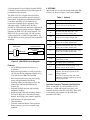
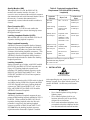
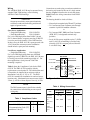
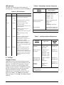
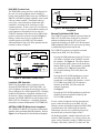
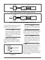
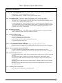
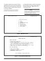
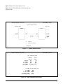
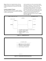
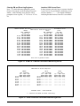
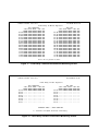
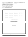
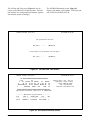
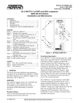
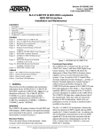
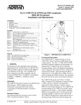
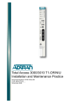
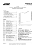
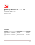
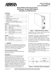
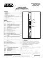
Section 61220010L2-5C
Issue 3, April 2001
CLEI # NCT1TX2B _ _
T200 IDSL OCU-R
Remote Termination Unit
Installation and Maintenance
CONTENTS
1. GENERAL .......................................................................... 1
2. OPTIONS ........................................................................... 2
3. INSTALLATION ............................................................... 3
4. TESTING ............................................................................ 5
5. CONTROL PORT OPERATION ...................................... 7
6. REMOTE PROVISIONING AND DIAGNOSTICS ...... 16
7. MAINTENANCE ............................................................. 16
8. DEPLOYMENT GUIDELINES ...................................... 16
9. WARRANTY AND CUSTOMER SERVICE ................ 16
IDSL
OCU-R
1220010
SYNC
CRC
NO
DSU
AP
NTWK
LBK
CUST
LBK
LBK
FIGURES
Figure 1. IDSL OCU-R ......................................................... 1
Figure 2. IDSL/DDS Circuit Diagram ................................. 2
Figure 3. Circuit Card Pin Assignments ............................... 4
Figure 4. IDSL/DDS Trouble Codes .................................... 6
Figure 5. ADTRAN U-BR1TE Bidirectional Loopback ..... 6
Figure 6. IDSL/DDS Remote End Initiated Loopback,
Local Loop ............................................................ 7
Figure 7. IDSL/DDS Remote End Initiated Loopback,
Customer Loop ...................................................... 7
Figure 8. RS-232 (DB-9) Pin Assignments .......................... 7
Figure 9. Main Menu Screen ................................................ 9
Figure 10. Terminal Modes Menu Screen .............................. 9
Figure 11. System Status Screen .......................................... 10
Figure 12. IDSL Detailed Status Screen ............................... 10
Figure 13. Loopbacks Screen ................................................ 11
Figure 14. Performance Monitoring Screen ......................... 11
Figure 15. U-BR1TE 15-Minute Performance Monitoring
Screen .................................................................. 12
Figure 16. U-BR1TE 24-Hour Performance Monitoring
Screen .................................................................. 12
Figure 17. Frame Relay 15-Minute Performance Monitoring
Screen .................................................................. 13
Figure 18. Frame Relay 24-Hour Performance Monitoring
Screen .................................................................. 13
Figure 19. Event Log Screen ................................................ 14
Figure 20. Set Circuit ID Screen ........................................... 14
Figure 21. Set Date and Time Screen ................................... 15
Figure 22. ADTRAN Information Screen ............................ 15
TABLES
Table 1. Options ..................................................................
Table 2. Protected Loopback Mode Requirement
T1E1.2/99-007R1 (Latching Loopback) ..............
Table 3. Compliance Codes ................................................
Table 4. Wiring Connections ..............................................
Table 5. LED Indicators ......................................................
Table 6. Alternating Loopback Sequences .........................
Table 7. Latching Loopback Sequences .............................
Table 8. Definition of Screen Abbreviations ......................
61220010L2-5C
2
3
4
4
5
5
5
8
SW 2
SC
64
56
19.2
O
F
F
9.6
4.8
2.4
SW
56
-10
dB
QM
EC
LL
EN
O
F
F
SW 4
SW 1
Frame IQ
LISTED
CUSTOM
TELECOM
E190349
Figure 1. IDSL OCU-R
1. GENERAL
This practice provides installation and maintenance
procedures for the IDSL OCU-R Remote Termination
Unit. Figure 1 is an illustration of the ADTRAN
IDSL OCU-R (P/N 1220010L2).
Revision History
Issue three of this document replaces the term IDSL-R
with OCU-R, where it is appropriate.
Description
The ADTRAN IDSL OCU-R is a termination unit
designed to deliver data rates up to 64 kbps and
provide testing functionality at the customer premises.
The IDSL OCU-R converts an industry standard
Trademarks: Any brand
names and product
names3
included in this document are
61220010L2-5,
Issue
trademarks, registered trademarks, or trade names of their respective holders.
1
2-wire Integrated Services Digital Network (ISDN)
U-interface to the traditional 4-wire DDS signal for
presentation to the customer.
The IDSL OCU-R is a digital network interface
device located at the customer premises point-ofdemarcation. In addition to terminating the ISDN
U-interface, the IDSL OCU-R functions as a
regenerative loopback device supporting Telcogenerated testing. The IDSL OCU-R unit is
available in T200 mechanics and can be optioned for
0 or -10 dB output toward the customer. Figure 2
illustrates the IDSL OCU-R Circuit Diagram. The
IDSL OCU-R is powered from -120 Vdc constant
voltage supplied by a U-BR1TE with PWR, or -48
Vdc provided by a locally powered T200 compatible
mounting.
Channel Bank
T-Carrier
U
B
R
1
T
E
Customer Premises
4-Wire Customer
Interface
2-Wire Loop
T/R Pair
IDSL OCU-R
Table 1. Options
Switch
Features
• 2-wire DDS deployment provided over a
U-interface.
• Dual powering capability; Locally powered by
-48 Vdc provided by mounting assembly or by
-120 Vdc from a U-BR1TE with PWR.
• DB-9 craft interface access for provisioning,
testing, and performance monitoring.
• Frame IQ/ADS-6 provide physical layer and
Frame Relay PM and inband PM access
respectively.
• Protected loopback prevents false latching
loobpack at 64 kbps.
• Switch selectable data rate including subrates,
19.2 and 56 kbps rates, including secondary
channel, and 64 kbps clear channel capability.
• LED indicators for operational status.
• T200 mechanics.
• Transmits Abnormal Station Code upstream
during out-of-service 4-wire customer loop
condition.
Description
SC
ON selects the Secondary Channel if 56,
19.2, 9.6, 4.8, or 2.4 are selected
64
ON selects 64k clear channel data
56
ON selects 56k data and, if SC = ON,
selects 56k secondary channel data
19.2
ON selects 19.2k data and, if SC = ON,
selects 19.2k secondary channel data
9.6
ON selects 9.6k data rate and, if SC = ON,
selects 9.6k secondary channel data
4.8
ON selects 4.8k data rate and, if SC = ON,
selects 4.8k secondary channel data
2.4
ON selects 2.4k data rate and, if SC = ON,
selects 2.4k secondary channel data
DSU/CSU
Figure 2. IDSL/DDS Circuit Diagram
2
2. OPTIONS
Options and rate are selected with the front panel DIP
switches as shown in Figure 1 and listed in Table 1.
SW56
ON selects Switched 56 operation
-10 dB
ON reduces DDS transmit signal by
approximately 10 dB
QM
ON enables quality monitoring
EC
ON selects error correction mode. Only
valid for rates of 19.2k or lower
LLEN
ON allows unit to respond to latching
loopbacks; unit always responds to nonlatching loopbacks
OFF while in 64k data mode will enable
PLB feature; latching loopbacks are always
enabled in this mode
Customer Interface Transmit Line Build Out
When -10 dB (SW1-1) is ON, the IDSL OCU-R
transmits a -10 dB AMI signal across the 4-wire
customer interface toward the CSU/DSU. When OFF
is selected the unit transmits a 0 dB AMI signal
toward the CSU/DSU.
61220010L2-5, Issue 3
61220010L2-5C
Quality Monitor (QM)
When QM (SW1-2) is ON, the IDSL OCU-R
monitors the customer interface for errors. If
excessive errors are detected the unit blocks customer
data transmission and sends Abnormal Station Code to
the network. Customer data transmission is
automatically restored when the trouble condition is
cleared.
Error Correction (EC)
When EC (SW1-3) is ON, the unit enables the
appropriate technique to ensure data integrity across
the digital network.
Latching Loopback Enabled (LLEN)
When LLEN (SW1-4) is ON, the IDSL OCU-R will
respond to latching loopback sequences.
False Loopback Immunity
ADTRAN’s Protected Loopback family of channel
units include an algorithm compatible with SARTS,
Hekimian, TPI, and other test systems that virtually
eliminates false latching loopback occurrences. This
algorithm is always enabled at 64 kbps. In addition,
ADTRAN’s Protected Loopback family features a
Protected Loopback mode for further false latching
loopback protection.
Latching Loopback
During operation up to 56 kbps, with LLEN enabled
(SW1-4 ON), the IDSL OCU-R will respond to the
legacy OCU latching loopback sequences and
translates CSU latching loopback sequences to the
DSU/CSU per TR62310 and ANSI T1.417. With
LLEN OFF, the IDSL OCU-R will not respond to
latching loopback.
At 64 kbps the function of the LLEN switch is altered.
At 64 kbps, placing LLEN ON will permit the IDSL
OCU-R to respond to the legacy latching loopback
sequence per TR62310 and ANSI T1.417. At 64
kbps, with LLEN OFF, the IDSL OCU-R enables
ADTRAN’s Protected Loopback.
Protected Loopback
ADTRAN’s Protected Loopback supports the new
proposed DDS latching loopback standard in T1E1.2/
99-007R1. When enabled, the IDSL OCU-R will
respond to latching loopback when the idle code
preamble is sent prior to the latching loopback
sequence specified in TR62310 and ANSI T1.417.
See Table 2 for the latching loopback sequence
requirement when Protected Loopback is enabled.
61220010L2-5C
Table 2. Protected Loopback Mode
Requirement T1E1.2/99-007R1 (Latching
Loopback)
Sequence
Function
Byte Code
# of Received
Bytes
Exit data
protocol
Idle - 11111110
Minimum of
35 Idle bytes
Clear existing
loopbacks
Transition in
progress (TIP)
X0111010
Minimum of
35 TIP bytes
Identify device
to be looped
Loopback select
code (LSC)
X0000101 - DS0
X1010101 - OCU
X0110001 - CSU
Minimum of
35 LSC bytes
Prepare to loop;
send MAP code
after 30 bytes
Loopback
enabled (LBE)
X1010110
Minimum of
100 LBE bytes
Activate
loopback
Far-End voice
(FEV)
X1011010
Minimum of
32 FEV bytes
Minimum of 35 TIP bytes required to disable
established latching loopback.
X = Don't care bit
3. INSTALLATION
C A U T I O N !
SUBJECT TO ELECTROSTATIC DAMAGE
OR DECREASE IN RELIABILITY.
HANDLING PRECAUTIONS REQUIRED.
After unpacking the unit, inspect it for damage. If
damage is noted, file a claim with the carrier, then
contact ADTRAN. See Warranty and Customer
Service.
•
•
•
61220010L2-5, Issue 3
WARNING
Never install telephone wiring during a
lightning storm.
Never install telephone jacks in wet
locations unless the jack is specifically
designed for wet locations.
Never touch uninsulated telephone wires
or terminals unless the telephone line has
been disconnected at the network interface.
3
Wiring
The ADTRAN IDSL OCU-R may be mounted in any
standard T400/T200 housing, or the following
ADTRAN T400/T200 housings:
CAUTION
On span-powered units, ensure ground continuity
exists between the unit, the housing, and a known
approved ground source.
Span Power Applications
• Single Mount Housing
P/N 1212007L1
• Dual Mount Housing
P/N 1212008L1
For 2-wire DDS deployment from D4/SLC-96 and
SLC-5 channel banks, a repeater powering U-BR1TE
is used to provide the metallic 2-wire DDS interface.
In these cases, the IDSL OCU-R is span-powered with
-120 Vdc and the customer premises installation
should include a span-powered mounting.
Local Power Applications
• Single Mount Housing
P/N 1212007L2
For 2-wire DDS deployment from non-ADTRAN
digital loop carrier U-BR1TEs, the IDSL OCU-R must
be locally powered with customer provided AC. For
these applications a local powered T400/T200
mounting is required.
Table 3 shows the Compliance Codes for the IDSL
OCU-R. The IDSL OCU-R complies with the
requirements covered under UL 1459 third edition and
is intended to be installed in an enclosure with an
Installation Code (IC) of “B” or “E”. The IDSL
OCU-R is intended for installation in restricted access
locations only. Maximum input current at max load is
32 mA @ -48 Vdc with an output of 6 mA @ 10 Vdc.
NOTE
The DDS customer port is classified as suitable
for connection to intra-building or non-exposed
wiring only.
Table 3. Compliance Codes
Code
Input
Output
Power Code (PC)
Telecommunication Code (TC)
F
X
C
–
Installation Code (IC)
A
–
4
Connections are made using screwdown terminals on
the barrier strip located in the rear of a single mount
housing. Figure 3 describes the circuit card pinout.
Table 4 shows the wiring connections for the IDSL
OCU-R.
The housing should be wired as follows:
• Network pair to terminal strip TR and TT positions.
• To Customer and From Customer pairs through
customer 8-pin RJ-48 modular connector.
or
• To Customer (DRT, DRR) and From Customer
(DTR, DTT ) to designated terminal strip
positions.
• Local -48 Vdc power supplied to pins 17 (GND)
and 35 (-48 Vdc) of mounting is provided only
when the OCU-R is not span-powered from the
2-wire IDSL loop.
IDSL OCU-R
-48 Vdc RET
17
11
-48 Vdc PWR
35
27
41
55
47
49
(TT)
To
Network
(TR)
5
15
Frame Ground
(DTT)
From
Customer
(DTR)
(DRT)
To
Customer
(DRR)
Figure 3. Circuit Card Pin Assignments
Table 4. Wiring Connections
Terminal Strip
Designations
T400 Pin
Number
To/From
Network
TT, TR
41, 47
To
Customer
(Rx)
DRT, DRR
5, 15
7, 8
From
Customer
(Tx)
DTR, DTT
49, 55
1, 2
Pair
61220010L2-5, Issue 3
Customer
RJ-48
61220010L2-5C
LED Indication
The IDSL OCU-R front panel LEDs display the
operating status. The LEDs are described in Table 5.
Table 5. LED Indication
LED
Color
SYNC
CUST LBK
Received Bytes
Activate loopback
Four consecutive bytes of
specified loopback code
X0101010 - OCU
X0101000 - CSU
X0101100 - DSU
Maintain loopback and
test for bit errors
Data byte alternating with
loopback code
example:
XDDDDDD1/X0101010
Clear loopback
Four consecutive data bytes
without CSU loopback code
Description
RED ON indicates that there are CRC errors.
OFF indicates no CRC errors.
YELLOW ON indicates no signal, no sealing
current, no SC framing.
OFF indicates signal, sealing current, and
SC framing achieved.
AP
NTWK LBK
Sequence
Function
RED Indicates that there is no network sync.
Indicates network synchronization.
GREEN
CRC
NO DSU
Table 6. Alternating Loopback Sequences
GREEN ON indicates that the unit has been
remotely provisioned.
FLASHING indicates remote control link
active.
OFF indicates locally provisioned
operation.
YELLOW ON indicates a loopback towards the
network is invoked at RT's DDS
Customer interface in response to Test
Center issuing OCU loopback.
FLASHING indicates loopback toward
network is invoked at CSU/DSU via
network commanded CSU loopback, and
RT's response of reversing sealing current
to CSU/DSU.
YELLOW ON indicates a loopback towards the
customer is invoked at IDSL OCU-R
interface via front panel LBK button.
FLASHING indicates a loopback towards
the customer is invoked at the ADTRAN
U-BR1TE via IDSL OCU-R front panel
LBK button.
4. TESTING
Loopback Testing
Loopback tests can be performed from the Central
Office (CO) to verify proper loop and IDSL OCU-R
operation. The IDSL OCU-R provides a network
loopback in response to an OCU latching or nonlatching loopback command. The IDSL OCU-R also
provides a sealing current reversal when the CSU
loopback command is detected. Alternating
loopbacks may be performed at all rates, except 64
kbps Clear Channel. See Table 6 for alternating
loopback sequences. See Table 7 for latching loopback
sequences.
61220010L2-5C
X = Don't care bit
Table 7. Latching Loopback Sequences
Sequence
Function
Clear existing
loopbacks
Byte Code
Transition in
progress (TIP)
X0111010
Number of
Received
Bytes
Minimum of
35 TIP bytes
Identify device to Loopback select
code (LSC)
be looped
X0000101 - DS0
X1010101 - OCU
X0110001 - CSU
Minimum of
35 LSC bytes
Prepare to loop;
send MAP code
after 30 bytes
Loopback enabled
(LBE)
X1010110
Minimum of
100 LBE bytes
Activate
loopback
Far-End voice
(FEV)
X1011010
Minimum of
32 FEV bytes
Minimum of 35 TIP bytes required to disable established
latching loopback.
X = Don't Care bit
61220010L2-5, Issue 3
5
IDSL/DDS Trouble Code
The IDSL/DDS system provides a quick diagnosis in
the case of a circuit condition where continuity is
broken when the IDSL/DDS circuit uses ADTRAN UBR1TEs with DDS Loopback capability in the central
office or remote terminal. The trouble code type
received by a tester determines whether the open
condition is occurring on the local loop or at the
customer premises. In the event of a 2-wire DSL loss
of signal, loss of sync, or open condition caused by an
open conductor or disconnected 2-wire loop, the
U-BR1TE transmits a Mux-Out-of-Sync (MOS 9Ah)
trouble code into the network as shown in Figure 4.
During a similar out-of-service condition at the
customer premises, the IDSL OCU-R transmits
Abnormal Station Code (ASC 9Eh) upstream into the
network as shown in Figure 4.
Channel Bank
Open 2-wire Loop
U
MOS 9Ah
Customer Premises
IDSL OCU-R
Test
Set
Bidirectional
loopback
Figure 5. ADTRAN U-BR1TE Bidirectional
Loopback
Remote End Initiated LBK Tests
The U-BR1TE supports loopbacks generated from the
IDSL OCU-R which allow testing to be performed
without coordination with the CO or test center.
Loopbacks initiated by the IDSL OCU-R front panel
LBK pushbutton (SW2) aid in system turn-up testing
or troubleshooting from the remote end.
The U-BR1TE responds to a loopback command
initiated at the IDSL OCU-R as follows:
B
R
OCU-R
1
DSU
T
E
Customer Premises
Channel Bank
U
ASC 9Eh
ADTRAN
U-BR1TE
B
R
1
Open 4-Wire Customer
Interface
ASC 9Eh
OCU-R
DSU
T
E
Figure 4. IDSL/DDS Trouble Codes
Loopback LED Operation
IDSL OCU-R loopback status is indicated via the
faceplate NTWK LBK and CUST LBK LEDs. An
active loopback occurring at the unit being viewed is
always indicated via a solid loopback LED. A flashing
loopback LED indicates a loopback condition at the
far end unit. When a loopback towards the network is
initiated, the NTWK LBK LED on the faceplate of the
IDSL OCU-R is illuminated. A loopback generated
towards the customer illuminates the CUST LBK LED.
ADTRAN U-BR1TE Bidirectional Loopback
The ADTRAN U-BR1TE will execute a bidirectional
loopback when performing DS0 DP loopbacks. Refer to
Figure 5 for an illustration of the bidirectional loopback.
Pressing the LBK pushbutton on the OCU-R once
will initiate a loopback at the U-BR1TE towards
the customer. See Figure 6. This allows data to
be sent from the remote end to test the local loop
and the IDSL OCU-R. This loopback is indicated
by a flashing CUST LBK LED on the IDSL
OCU-R and a flashing TEST LED (D4) on the
U-BR1TE.
Pressing the OCU-R LBK pushbutton a second
time initiates a loopback at the IDSL OCU-R
towards the 4-wire DDS (CPE) interface. A solid
CUST LBK on the IDSL OCU-R indicates a
loopback at the IDSL OCU-R towards the
customer equipment.
See Figure 7.
Pressing the OCU-R LBK pushbutton a third time
disables all current loopbacks initiated by the
OCU-R LBK pushbutton.
If errors exist the loopbacks can help determine the
source; either the local loop or the IDSL OCU-R.
During a remote end initiated loopback the IDSL/DDS
system transmits ASC 9Eh towards the network,
indicating an out-of-service condition generated by
the remote end, as shown in Figures 6 and 7.
All latching loopbacks, whether initiated by the craft
interface, LBK pushbutton, CO, or from a remote test
center, can be released by sending 35 DDS loop down
TIP bytes <X0111010> (where X is a “don’t care” bit).
6
61220010L2-5, Issue 3
61220010L2-5C
4-Wire
CPE Interface
ASC 9Eh
U-BR1TE
Local Loop
IDSL
OCU-R
Loopback
Pushbutton
Test
Set
Push once for
U-BR1TE Loopback
Figure 6. IDSL/DDS Remote End Initiated Loopback, Local Loop
4-Wire
CPE Interface
ASC 9Eh
ASC 9Eh
IDSL
OCU-R
Loopback
Pushbutton
U-BR1TE
Local Loop
Test
Set
Push twice for IDSL OCU-R
Loopback
Figure 7. IDSL/DDS Remote End Initiated Loopback, Customer Loop
All existing latching loopbacks can also be disabled
by pressing the TEST or LBK pushbutton on the
U-BR1TE or remote unit, respectively.
NOTE
The remote end test feature is only supported
when the upstream U-BR1TE is an ADTRAN
D4 or Series 5 U-BR1TE with DDS Loopback
capability. Other U-BR1TEs will ignore the
loopback command sent by pressing the IDSL
OCU-R LBK button.
5. CONTROL PORT OPERATION
The IDSL OCU-R front panel DB-9 provides an
RS-232 interface for connection to a controlling
terminal. The pinout of the DB-9 is illustrated in
Figure 8.
6
7
8
9
1
2
3
4
5
TXD (Transmit Data)
RXD (Receive Data)
SGN (Signal Ground)
Figure 8. RS-232 (DB-9) Cable Side Pin
Assignments
61220010L2-5C
NOTE
When conducting a Terminal Session, always
select VT100 mode prior to making the craft
connection.
The terminal interface operates at data rates from
1.2 kbps to 19.2 kbps. The asynchronous data format
is fixed at 8 data bits, no parity, and 1 stop bit. The
supported terminal type is VT100 or compatible.
NOTE
If using a personal computer (PC) with terminal
emulation capability, disable all power saving
programs. Otherwise, communication between
the PC and the IDSL OCU-R unit can be
disrupted, resulting in misplaced characters or
screen timeouts.
Operation
The T200 IDSL OCU-R is ready for synchronization
and operation upon insertion in an active shelf or
housing. Terminal sessions provide access to screen
menus for provisioning, monitoring, testing, or
obtaining performance history. Terminal session
screen access is available at any time during
operation. The screens shown in this practice identify
the main menu screens; subordinate screens are not
depicted. Abbreviations used in the screen diagrams
are detailed in Table 8.
61220010L2-5, Issue 3
7
Table 8. Definition of Screen Abbreviations
Abbreviation and Definition
ES – Errored Seconds: A count of the number of seconds in which at least one code violation was detected on a
OOO
digital circuit.
O
•O IDSL Interface ....Second in which a CRC error occurs.
O
•O Customer DDS Interface....Second in which a bipolar violation occurs.
OO
UAS – Unavailable Seconds: A count of the number of seconds that a circuit or path is not available.
O
•O IDSL Interface (U-Interface) ....Will accumulate upon the loss of loop synchronization or
OO
the occurrence of 7 errored seconds in a period of 20 seconds. UAS will stop accumulating upon the
OO
occurrence of 30 consecutive non-errored seconds.
O
•O Customer DDS Interface.... Will accumulate upon the loss of sealing current (LOOP OPEN), loss of
OO
receive signal (LOS), loss of secondary channel framing (LOF), or when the illegal bipolar violation
OO
error rate is >1E-3 for at least 10 seconds. UAS will stop accumulating upon the occurrence of 10
OO
consecutive non-severely errored seconds.
BPV – Illegal Bipolar Violation
O
•O Customer DDS Interface.... Two consecutive pulses of the same polarity or violation received that
OO
does not alternate in polarity with respect to the prior violation.
INV – Invalid Frame Relay Frame
O
•O Any frame with a CRC error.
O
•O Any frame containing fewer than five octets.
O
•O Any frame containing more than 8191 octets.
O
•O Any frame that does not contain an integral number of octets.
O
•O Any frame containing a frame abort.
OO
FECN – Forward Explicit Congestion Notification
O
•O Count of frames in which the Forward Explicit Congestion Notification bit was set.
O
•O Indicates congestion in the frame relay network but does not isolate cause or location of congestion.
BECN – Backward Explicit Congestion Notification
O
•O Count of valid frames in which the Backward Explicit Congestion Notification bit was set.
O
•O Indicates congestion in the frame relay network but does not isolate cause or location of congestion.
LMI – Local Management Interface
O
•O Local Management Interface (LMI) status is a monitor of the heart beat between the frame switch and
OO
the CPE.
O
•O Recognizes FRF (Annex A), ANSI T1.617 Annex D, and ITU T.933A frame relay interfaces.
O
•O Network and Customer LMI counts should be equal if everything is ok between the frame switch
OO
and the CPE.
O
•O Maintains counts of LMI status messages monitored by the U-Interface, which are sent by the frame
OO
relay switch.
O
•O Maintains counts of LMI status inquiry messages monitored at the DDS Interface which are sent by
OO
the frame relay CPE.
%UT – Frame Relay Percent Utilization
O
•O The average percent utilization over the DS0 channel.OO
8
61220010L2-5, Issue 3
61220010L2-5C
To conduct a terminal session, connect a VT100 or
compatible test set to the OCU-R via the front panel
DB-9 connector, then press the space bar three times
to initiate the session. The Main Menu will appear,
as illustrated in Figure 9.
A Terminal Modes Menu is available for configuring
the craft interface for a manual terminal update or a
real-time terminal update. Figure 10 shows the
Terminal Modes Menu.
NOTE
Real-time terminal update is recommended for
normal terminal operation unless screens are to
be captured or logged to a print file.
The Main Menu provides access to detailed
performance and configuration information.
CIRCUIT ID:IDSL Test Unit
07/25/00 02:14:40
Adtran IDSL Main Menu
1.
2.
3.
4.
5.
6.
7.
8.
Status
Loopbacks
Performance Monitoring
Event Log
Set Circuit ID
Set Date and Time
Adtran Information
Terminal Modes
Selection:
Figure 9. Main Menu Screen
CIRCUIT ID:IDSL Test Unit
07/25/00 02:39:56
TERMINAL MODES MENU
MANUAL UPDATE MODE:
* You can print or log screens
* No text is highlighted
* “Ctrl+R to Update” appears at the top of each screen, reminding
you to press both the ‘Ctrl’ and ‘R’ keys to update the screen
* There is a delay between screen changes & updates
* After 30 min. of no interaction, a new baud rate search is begun
* Ignores input until screen is finished printing
REAL-TIME UPDATE MODE:
*
*
*
*
Faster of the two modes
You cannot print screens to a log file
Highlighting is enabled
Recommended for daily operation
Press <SPACEBAR> to toggle update modes
Figure 10. Terminal Modes Menu Screen
61220010L2-5C
61220010L2-5, Issue 3
9
Figure 11 shows the System Status screen.
Figure 12 shows Detailed Status for both network and
customer loops.
CIRCUIT ID:IDSL Test Unit
07/25/00 02:31:30
System Status Screen
Channel Bank
DDS Loop
____________
____________
|
UBR1TE
|
|
OCU-R
|
|
|
|
|------>
|
|
|
|
|
|
|
|
|
|
|
|
NETWORK|
|<000------------------000>|
|CUSTOMER
|
|
|
|
|
|
MARGIN -----> 20|
| ATTEN
|
|
|
|
00dB
|
|
|
|<-----|____________|
|____________|
1.
2.
Legend
Detailed Status
Selection:
Figure 11. System Status Screen
CIRCUIT ID:IDSL Test Unit
07/25/00 02:33:20
IDSL INTERFACE DATA
UBR1TE
OCU-R
(CUST)
(NET)
-------------MARGIN:
N/A
20
ES 15MIN:
000
000
UAS 15MIN:
000
000
CRC 15MIN: 00000
00000
DSL ALARMS: <
NONE
>
CUSTOMER DDS RECEIVER DATA
ES 15MIN:
UAS 15MIN:
ILL BPV 15MIN:
CUSTOMER ALARMS:
LOOP ATTENUATION:
000
000
00000
NONE
00dB
Figure 12. IDSL Detailed Status Screen
10
61220010L2-5, Issue 3
61220010L2-5C
Figure 13 shows the Loopbacks display, allowing
loopback testing to be initiated or terminated while
graphically displaying the testing status of the IDSL
system.
Latching Loopback Timeout
When latching loopback timeout is enabled, latching
loopbacks will drop out after 120 minutes returning the
system to normal operation.
At the top right corner of the screen the time display
indicates the current time. At each 15-minute interval,
the performance information is transferred to the
15-minute performance data registers accessed from
the Performance Monitoring screen. All 15-minute
performance data registers are available for the last 25
hours. At each 24-hour interval, the performance data
is transferred into the 24-hour performance data
register also accessed using this screen. The
Performance Monitoring screens are shown in Figure
14 through Figure 18.
CIRCUIT ID:IDSL Test Unit
07/25/00 02:33:55
LOOPBACKS
Channel Bank
DDS Loop
____________
____________
|
UBR1TE
|
|
OCU-R
|
|
|
|
|------>
|
|
|
|
|
|
|
|
|
|
|
|
NETWORK|
|<------------------------>|
|CUSTOMER
|
|
|
|
|
|
|
|
|
|
|
|
|
|
|
|<-----|____________|
|____________|
1.
2.
3.
4.
5.
Loop UBR1TE Toward Customer—< Not Available >
Loop OCU-R Toward Network
Loop OCU-R Toward Customer
Deactivate Loopback
Loopback Timeout: Disabled
Selection:
Figure 13. Loopbacks Screen
CIRCUIT ID:IDSL Test Unit
07/25/00 02:36:07
Performance Data
---------------------------------------1.
2.
3.
4.
5.
UBR1TE/OCU-R 15 Minute Registers
UBR1TE/OCU-R 24 Hour Registers
Frame Relay 15 Minute Registers
Frame Relay 24 Hour Registers
Clear Performance Statistics
Selection:
Figure 14. Performance Monitoring Screen
61220010L2-5C
61220010L2-5, Issue 3
11
Clearing PM and Event Log Registers
Press “5” at the Performance Monitoring screen
(Figure 14) to advance to the Warning screen (not
shown). At the Warning screen the user will be
prompted to clear registers; “Y” for Yes or “N” for
No.
Interface OOS Screen Event
In those instances when the loop or customer interface
is out of service, the performance monitoring screens
will show dashes (--- --- ---) for elapsed timeframes
indicating that data for those intervals is unavailable.
CIRCUIT ID:IDSL Test Unit
02:30
02:15
02:00
01:45
01:30
01:15
01:00
00:45
00:30
00:15
00:00
23:45
23:30
23:15
23:00
22:45
UBR1TE
IDSL INTERFACE
-ES-UAS--CRC000 000 00000
000 000 00000
000 003 00000
000 000 00000
000 000 00000
000 000 00000
000 000 00000
000 000 00000
000 000 00000
000 000 00000
000 000 00000
000 000 00000
000 000 00000
000 000 00000
000 000 00000
000 000 00000
000 000 00000
07/25/00 02:36:32
UBR1TE/OCU-R 15-Minute Registers
OCU-R
IDSL INTERFACE
-ES-UAS--CRC000 000 00000
02:30 000 000 00000
02:15 000 003 00000
02:00 000 000 00000
01:45 000 000 00000
01:30 000 000 00000
01:15 000 000 00000
01:00 000 000 00000
00:45 000 000 00000
00:30 000 000 00000
00:15 000 000 00000
00:00 000 000 00000
23:45 000 000 00000
23:30 000 000 00000
23:15 000 000 00000
23:00 000 000 00000
22:45 000 000 00000
OCU-R
DDS LOOP
-ES-UAS--BPV000 000 00000
000 000 00000
000 012 00035
000 000 00000
000 000 00000
000 000 00000
000 000 00000
000 000 00000
000 000 00000
000 000 00000
000 000 00000
000 000 00000
000 000 00000
000 000 00000
000 000 00000
000 000 00000
000 000 00000
Press “B” to go back 4 hours
Figure 15. U-BR1TE 15-Minute Performance Monitoring Screen
CIRCUIT ID:IDSL Test Unit
07/25/00 02:36:53
UBR1TE/OCU-R 24-Hour Registers
07/24
07/23
07/22
07/21
07/20
07/19
07/18
07/17
UBR1TE
IDSL INTERFACE
-ES----UAS---CRC00000 00003 00000
00015 00253 00321
----- ----- --------- ----- --------- ----- --------- ----- --------- ----- --------- ----- --------- ----- -----
07/24
07/23
07/22
07/21
07/20
07/19
07/18
07/17
REVERSED VIDEO
OCU-R
IDSL INTERFACE
-ES----UAS---CRC00000 00003 00000
00010 00253 00159
----- ----- --------- ----- --------- ----- --------- ----- --------- ----- --------- ----- --------- ----- -----
OCU-R
DDS LOOP
-ES----UAS---BPV00000 00012 00035
00014 01073 08442
----- ----- --------- ----- --------- ----- --------- ----- --------- ----- --------- ----- --------- ----- -----
= DATA OVERFLOW
* = Contains corrupted 15-minute interval(s)
Figure 16. U-BR1TE 24-Hour Performance Monitoring Screen
12
61220010L2-5, Issue 3
61220010L2-5C
CIRCUIT ID:IDSL Test Unit
02:30
02:15
02:00
01:45
01:30
01:15
01:00
00:45
00:30
00:15
00:00
23:45
23:30
23:15
23:00
22:45
07/25/00 02:37:18
Frame Relay 15-Minute Registers
IDSL INTERFACE
DDS LOOP
-INV--FECN--BECN---LMI--%UT
-INV--FECN--BECN---LMI--%UT
00000 00000 00000 00000 000
00000 00000 00000 00000 000
00000 00000 00000 00000 000
02:30 00000 00000 00000 00000 000
00000 00000 00000 00000 000
02:15 00000 00000 00000 00000 000
00000 00000 00000 00000 000
02:00 00000 00000 00000 00000 000
00000 00000 00000 00000 000
01:45 00000 00000 00000 00000 000
00000 00000 00000 00000 000
01:30 00000 00000 00000 00000 000
00000 00000 00000 00000 000
01:15 00000 00000 00000 00000 000
00000 00000 00000 00000 000
01:00 00000 00000 00000 00000 000
00000 00000 00000 00000 000
00:45 00000 00000 00000 00000 000
00000 00000 00000 00000 000
00:30 00000 00000 00000 00000 000
00000 00000 00000 00000 000
00:15 00000 00000 00000 00000 000
00000 00000 00000 00000 000
00:00 00000 00000 00000 00000 000
00000 00000 00000 00000 000
23:45 00000 00000 00000 00000 000
00000 00000 00000 00000 000
23:30 00000 00000 00000 00000 000
00000 00000 00000 00000 000
23:15 00000 00000 00000 00000 000
00000 00000 00000 00000 000
23:00 00000 00000 00000 00000 000
00000 00000 00000 00000 000
22:45 00000 00000 00000 00000 000
Press “B” to go back 4 hours
Figure 17. Frame Relay 15-Minute Performance Monitoring Screen
CIRCUIT ID:IDSL Test Unit
07/25/00 02:37:38
Frame Relay 24-Hour Registers
07/24
07/23
07/22
07/21
07/20
07/19
07/18
07/17
IDSL INTERFACE
-INV--FECN--BECN---LMI--%UT
00000 00000 00000 00000 000
65535 00000 00000 00000 000
----- ----- ----- ----- ------- ----- ----- ----- ------- ----- ----- ----- ------- ----- ----- ----- ------- ----- ----- ----- ------- ----- ----- ----- ------- ----- ----- ----- ---
REVERSED VIDEO
07/24
07/23
07/22
07/21
07/20
07/19
07/18
07/17
DDS LOOP
-INV--FECN--BECN---LMI--%UT
00000 00000 00000 00000 000
65535 00000 00000 00000 000
----- ----- ----- ----- ------- ----- ----- ----- ------- ----- ----- ----- ------- ----- ----- ----- ------- ----- ----- ----- ------- ----- ----- ----- ------- ----- ----- ----- ---
= DATA OVERFLOW
* = Contains corrupted 15-minute interval(s)
Figure 18. Frame Relay 24-Hour Performance Monitoring Screen
61220010L2-5C
61220010L2-5, Issue 3
13
The Event Log, shown in Figure 19, loads and timestamps IDSL circuit performance anomalies and
threshold violations. This screen is a very useful aid
in troubleshooting a chronic circuit. It monitors DDS
sync loss, DDS open loop, IDSL OCU-R margin,
IDSL sync loss, and power-up events. IDSL loop
signal-to-noise margin is calculated on a numerical
scale from 0-20 with 0 approximately equal to a BER
of 1 x 10 -6 and 20 equal to virtually a 0 BER.
The Set Circuit ID screen, Figure 20, sets the circuit
identification.
CIRCUIT ID:IDSL Test Unit
07/25/00 02:38:13
EVENT LOG
EVENT
FIRST
LAST
CURRENT
COUNT
DDS SYNC LOSS
DDS LOOP OPEN
07/24/00 11:10:04
07/24/00 11:10:04
07/24/00 20:45:03
07/24/00 20:45:03
CLEAR
CLEAR
255
020
OCU-R MARGIN
DSL SYNC LOSS
-------- -------07/24/00 11:10:04
-------- -------07/24/00 20:45:03
CLEAR
CLEAR
--021
OCU-R POWER
07/24/00 11:10:01
07/25/00 02:00:00
CLEAR
017
LAST LOG RESET
01/03/98 03:33:20
<ENTER>
<ESC>
To CLEAR the Event Log
To exit without destroying data
Figure 19. Event Log Screen
CIRCUIT ID:IDSL Test Unit
07/25/00 02:38:36
Set Circuit ID
New ID =
Figure 20. Set Circuit ID Screen
14
61220010L2-5, Issue 3
61220010L2-5C
The ADTRAN Information screen, Figure 22,
displays part number, serial number, CLEI code, and
unit revision for the IDSL OCU-R.
The Set Date and Time screen, Figure 21, may be
used to set the IDSL OCU-R date and time. Once the
date and time are configured the performance registers
date and time update accordingly.
CIRCUIT ID:IDSL Test Unit
07/25/00 02:39:01
Set System Date and Time
New Date =
/
/
(MM/DD/YY)
< Press TAB to cycle between time and date >
New Time =
:
:
(HH/MM/SS)
Figure 21. Set Date and Time Screen
CIRCUIT ID:IDSL Test Unit
07/25/00 02:39:32
## ###################################
# ##
##
#
##
###### ## ######
##
######
#
## ##
## ## ##
## # ## ##
##
########## ##
## ## ###### ###### ##
##
#
########
#####
###
####
##
Support Hours:
Emergency:
Phone:
Fax:
Internet:
7am - 7pm CST
7days x 24hrs
800.726.8663
256.963.6217
www.adtran.com
##############################################
901 Explorer Boulevard, Huntsville, AL 35806-2807
-----------Manufacturing Information----------Unit
PART #
SERIAL NUM
CLEI
REV
-------------- ---------- ---------- --OCU-R
1220010L2
123456789
NCT1TX2BAA
1
Figure 22. ADTRAN Information Screen
61220010L2-5C
61220010L2-5, Issue 3
15
6. REMOTE PROVISIONING AND
DIAGNOSTICS
Control Protocol
Remote access to provisioning and status information
is accomplished using ADTRAN Digital System 6
Message protocol, defined in Control and Diagnostic
Procedures Practice, Section 6032991-6. Digital
System 6 is supported by the TPI 108/109 and 105
portable test set and is supported by Hekimian React
2001 Release 1.900 remote test system. The IDSL
OCU-R network element complies with ANSI
T1.107-1995, “Digital Hierarchy Format
Specifications Annex G” which allows remote
provisioning, querying, and performance monitoring
via inband control of network elements.
NOTE
The REACT 2001 GUI software Release 1.900
supports ANSI T1.107-1995.
Remote access is accomplished using a defined set of
inband DS0 byte sequences similar to the latching
loopback sequence. Commands issued through the
test system are recognized by the individual channel
unit, which responds with the appropriate byte
sequences. These inband commands may be used to
verify options via dialogs with REACT 2001 and TPI
108/109 test sets. Unit CLEI, serial number,
provisioning, and performance information can be
retrieved remotely using the Digital System 6
protocol.
Provisioning and Status
All configuration options can be remotely viewed or
provisioned. The front panel AP LED indicator
Flashes during control link establishment and remains
ON after the IDSL OCU-R has been remotely
provisioned.
7. MAINTENANCE
The T200 IDSL OCU-R does not require routine
maintenance for normal operation.
8. DEPLOYMENT GUIDELINES
The IDSL OCU-R allows a standard U-interface to be
used to provide DDS over a single pair. Listed below
are the loop design guidelines for deployment of DDS
over IDSL.
• All loops must be nonloaded.
• Actual Measured Loss (AML) should not exceed
40 dB at 40 kHz (135 Ω termination), the Nyquist
frequency of a U-interface.
• Total bridged tap length should not exceed 2 kft.
NOTE
If any of the above Deployment Guideline criteria
are not met, design should be considered using
Total Reach DDS, with the exception of the first
bullet.
9. WARRANTY AND CUSTOMER SERVICE
ADTRAN will replace or repair this product within 10
years from the date of shipment if it does not meet its
published specifications or fails while in service (see
ADTRAN Carrier Networks Equipment Warranty,
Repair, and Return Policy and Procedure, document
60000087-10).
Contact Customer and Product Service (CAPS) prior
to returning equipment to ADTRAN.
If the IDSL OCU-R has been remotely provisioned,
the operator can alternate between remote
configuration and manual switch settings by pressing
the momentary LBK button located on the front panel
for 5 seconds. If the IDSL OCU-R is removed from
the system, the unit retains previous provisioning
information in nonvolatile RAM.
The AP LED remains ON when the IDSL OCU-R is
operating based on Remote Provisioning, and is OFF
when operating on manual switches. See Table 5 for
LED indication.
16
61220010L2-5, Issue 3
61220010L2-5C
For service, CAPS requests, or further information,
contact one of the following numbers:
ADTRAN Sales
Pricing/Availability
(800) 827-0807
ADTRAN Technical Support
Pre-sales Applications/Post-sales Technical Assistance
(800) 726-8663
Standard hours: Monday-Friday, 7 a.m. - 7 p.m. CST
Emergency hours: 7 days/week, 24 hours/day
ADTRAN Repair/CAPS
Return for Repair/Upgrade
(256) 963-8722
Repair and Return Address
ADTRAN, Inc.
CAPS
901 Explorer Boulevard
Huntsville, Alabama 35806-2807
61220010L2-5C
61220010L2-5, Issue 3
17
18
61220010L2-5, Issue 3
61220010L2-5C