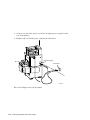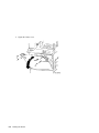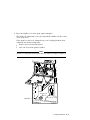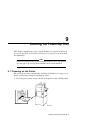
1
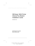
PrintServer 32 Printer
Installation Guide
Order Number: EK–LPS32–IG–001
Digital Equipment Corporation
Maynard, Massachusetts
First Printing, July 1992
The information in this document is subject to change without notice and should not be
construed as a commitment by Digital Equipment Corporation. Digital Equipment Corporation
assumes no responsibility for any errors that may appear in this document.
The software described in this document is furnished under a license and may be used or copied
only in accordance with the terms of such license.
No responsibility is assumed for the use or reliability of software on equipment that is not
supplied by Digital Equipment Corporation or its affiliated companies.
Restricted Rights: Use, duplication, or disclosure by the U.S. Government is subject to
restrictions as set forth in subparagraph (c)(1)(ii) of the Rights in Technical Data and Computer
Software clause at DFARS 252.227-7013.
© Digital Equipment Corporation 1992.
All Rights Reserved.
Printed in U.S.A.
The following are trademarks of Digital Equipment Corporation: A–to–Z, DECnet, DECprint,
DECwindows, DECwrite, Micro/VAX, MicroVMS, PrintServer, Scholar, TK, ULTRIX, VAX,
VAXcluster, VAX DOCUMENT, VAXstation, VMS, VT, and the DIGITAL logo.
PostScript is a registered trademark of Adobe Systems, Inc.
This document was prepared using VAX DOCUMENT, Version 2.0.
S1771
FCC NOTICE:
This equipment generates, uses, and may emit radio frequency. The equipment has been type
tested and found to comply with the limits for a Class A digital device pursuant to Part 15 of
FCC rules, which are designed to provide reasonable protection against such radio frequency
interference.
Operation of this equipment in a residential area may cause interference in which case the user
at his own expense will be required to take whatever measures may be required to correct the
interference.
This document was prepared using VAX DOCUMENT, Version 2.0.
Contents
Preface . . . . . . . . . . . . . . . . . . . . . . . . . . . . . . . . . . . . . . . . . . . . . . . . . . . . .
ix
1 Preparing to Install the Printer
1.1
1.1.1
1.1.2
1.1.3
1.2
1.3
Select a Site . . . . . . . . . . . . . . . .
Find a Wall Outlet . . . . . . . .
Provide Easy Access . . . . . . .
Find the Right Environment
Install the Software . . . . . . . . . .
Prepare the Network . . . . . . . . .
.
.
.
.
.
.
.
.
.
.
.
.
.
.
.
.
.
.
.
.
.
.
.
.
.
.
.
.
.
.
.
.
.
.
.
.
.
.
.
.
.
.
.
.
.
.
.
.
.
.
.
.
.
.
.
.
.
.
.
.
.
.
.
.
.
.
.
.
.
.
.
.
.
.
.
.
.
.
.
.
.
.
.
.
.
.
.
.
.
.
.
.
.
.
.
.
.
.
.
.
.
.
.
.
.
.
.
.
.
.
.
.
.
.
.
.
.
.
.
.
.
.
.
.
.
.
.
.
.
.
.
.
.
.
.
.
.
.
.
.
.
.
.
.
.
.
.
.
.
.
1–1
1–1
1–2
1–3
1–3
1–4
Unpacking the Kits . . . . . . . . . . . . . . . . . . . . . . . . . . . . . . . . . . .
Moving the Printer from the Shipping Pallet . . . . . . . . . . . . . . . .
Unpacking the Components . . . . . . . . . . . . . . . . . . . . . . . . . . . . .
2–2
2–5
2–10
2 Unpacking the Print Engine and Cabinet
2.1
2.2
2.3
3 Installing the Bottom Paper Tray
4 Installing the Paper Cassettes
4.1
4.2
4.3
Assembling the Paper Cassettes . . . . . . . . . . . . . . . . . . . . . . . . .
Adding Paper to the Paper Cassettes . . . . . . . . . . . . . . . . . . . . . .
Installing the Paper Cassettes . . . . . . . . . . . . . . . . . . . . . . . . . . .
4–1
4–2
4–5
v
5 Installing the Top Output Paper Tray Components
5.1
5.2
Assembling the Paper Tray Inserts . . . . . . . . . . . . . . . . . . . . . . .
Installing the Top Output Tray . . . . . . . . . . . . . . . . . . . . . . . . . .
5–1
5–4
6 Adding Toner and Installing the OPC Drum
6.1
6.2
Adding Toner . . . . . . . . . . . . . . . . . . . . . . . . . . . . . . . . . . . . . . .
Installing the OPC Drum . . . . . . . . . . . . . . . . . . . . . . . . . . . . . . .
6–1
6–12
7 Connecting Ethernet and Power Cables
7.1
7.2
7.3
Connecting the Ethernet Cable . . . . . . . . . . . . . . . . . . . . . . . . . .
Connecting the ThinWire Ethernet Cable . . . . . . . . . . . . . . . . . .
Connecting the Power Cable . . . . . . . . . . . . . . . . . . . . . . . . . . . .
7–3
7–7
7–11
8 Leveling the Printer
9 Running the Power-Up Test
9.1
9.2
Powering on the Printer . . . . . . . . . . . . . . . . . . . . . . . . . . . . . . . .
If You Encounter Problems . . . . . . . . . . . . . . . . . . . . . . . . . . . . .
9–1
9–4
Index
Figures
1
1–1
2–1
2–2
7–1
vi
Shipping Boxes . . . . . . .
Space Requirements . . . .
Shipaway Kit A . . . . . . .
Shipaway Kit B . . . . . . .
Ethernet Block Diagram
.
.
.
.
.
.
.
.
.
.
.
.
.
.
.
.
.
.
.
.
.
.
.
.
.
.
.
.
.
.
.
.
.
.
.
.
.
.
.
.
.
.
.
.
.
.
.
.
.
.
.
.
.
.
.
.
.
.
.
.
.
.
.
.
.
.
.
.
.
.
.
.
.
.
.
.
.
.
.
.
.
.
.
.
.
.
.
.
.
.
.
.
.
.
.
.
.
.
.
.
.
.
.
.
.
.
.
.
.
.
.
.
.
.
.
.
.
.
.
.
.
.
.
.
.
.
.
.
.
.
.
.
.
.
.
.
.
.
.
.
xii
1–2
2–2
2–4
7–2
Tables
4–1
Paper Cassette Configurations . . . . . . . . . . . . . . . . . . . . . . . .
4–1
vii
Preface
This guide covers the installation of the PrintServer 32 hardware up to the
point where it is certified to be operating properly after the software is loaded
into the system.
Note
All procedures should be performed in the order given. If you have a
problem during the installation, see Section 9.2 for assistance.
Associated Documents
In addition to this guide, refer to the following manuals from the Software Kit
to complete the installation of the printer:
VMS:
DEC PrintServer Supporting Host Software for VMS Installation Guide
DEC PrintServer Supporting Host Software for VMS Management Guide
DECprint Printing Services Software Installation Guide
ULTRIX:
DEC PrintServer Supporting Host Software for ULTRIX Installation Guide
DEC PrintServer Supporting Host Software for ULTRIX Management
Guide
Installation Guide: PrintServer Client for ULTRIX
These guides explain how to install the PrintServer supporting host and client
software on a VMS or ULTRIX system. The supporting host software enables
the VMS host to function as a supporting host to a remote PrintServer 32
printer. The client software provides users with remote printing facilities on
the PrintServer 32 printer.
ix
For VMS, the supporting host and DECprint Printing Services software can be
installed on the same VMS system.
Conventions
The following terms and conventions are used in this guide:
Term/Convention
Meaning
Note
Provides additional information.
Caution
Provides information for preventing equipment or
software damage.
Warning
Provides information for preventing personal injury.
OPC
The organic photo conductor is the type of drum the
printer uses. OPC drums can be disposed of without
taking any special precautions.
Bullet ( )
A bulleted statement describes a result after performing
a step. For example:
1. Press the Pause key to place the printer off line.
•
Arrow (
)
The off-line indicator lights.
Indicates a special instruction. For example:
1. Remove the toner cartridge from the drawer by
lifting it straight up.
Bold
Discard the toner cartridge.
Text in boldface designates messages that appear on the
operator panel.
Laser Safety
The PrintServer 32 printer complies with laser product performance standards
set by government agencies as a Class 1 Laser Product. The PrintServer 32
printer does not emit hazardous light, since the beam is enclosed during all
modes of customer operation and maintenance.
Warning
Use of controls or adjustment procedures other than those specified in
this guide may result in hazardous laser light exposure.
x
Ozone Safety
The PrintServer 32 printer uses an ozone filter to remove the ozone generated
by the printer. Be sure to replace the ozone filter each time user maintenance
is performed on the printer.
Warning
Do not operate the printer without the ozone filter installed. The filter
removes ozone that may cause eye or respiratory irritation.
Before You Start
Before you install the PrintServer 32 printer, be sure you have the following
items (see Figure 1):
•
Print engine and cabinet (packaged in one box). Also in this box are
Shipaway Kits A and B. See Chapter 2 for items supplied in the shipaway
kits.
•
Bottom paper tray, shipped in its own box.
•
Software Kit (optional), which contains software documentation and media.
•
Country Kit (non-U.S. only), which contains translated hardware
documentation, overlays, labels, and the appropriate power cord.
If any items are missing or damaged, immediately contact your sales
representative and delivery agent or your DECdirect customer service
representative.
Special Tools
The only tools you need to install the PrintServer 32 printer are the open-end
wrench and the Phillips screwdriver supplied in Shipaway Kit B. You need a
razor knife to open the boxes.
Warning
The printer is heavy. To avoid injury, use two people to roll the printer
down the shipping pallet ramp. Do not attempt to roll the printer down
the shipping pallet alone.
xi
Figure 1 Shipping Boxes
xii
1
Preparing to Install the Printer
Before you unpack and install the PrintServer 32 printer, perform the following
tasks:
•
Select a site
•
Install the software on your system
•
Prepare the network
1.1 Select a Site
The proper site for the PrintServer 32 printer includes the following:
•
A wall outlet
•
Space around the unit for easy access
•
Appropriate environmental conditions
1.1.1 Find a Wall Outlet
Select a wall outlet with the correct voltage and adequate amperage to supply
power to the printer. The power requirements for the PrintServer 32 printer
are:
Voltage
Frequency
Amperage
120 Volts
60 Hz
20-Amp circuit
240 Volts
50 Hz
8-Amp circuit
Do not plug other equipment that draws high levels of current, such as coffee
pots, office copiers, or air conditioners, into the same power supply line.
Exceeding the amperage rating trips the circuit breaker of the power supply
line.
Preparing to Install the Printer 1–1
1.1.2 Provide Easy Access
Find an area that allows users access to the printer:
•
A level floor
•
Enough surrounding space to allow ventilation and easy access to all sides
of the printer for servicing and adding paper. Make sure the user can face
the opening of the bottom paper tray.
Figure 1–1 illustrates the space requirements for the printer.
Figure 1–1 Space Requirements
1–2 Preparing to Install the Printer
1.1.3 Find the Right Environment
The PrintServer 32 printer works best in an area that is:
•
At a temperature range of 10° to 32°C (50° to 90°F) and a humidity range
of 20% to 80%. This ensures consistent image quality and prevents paper
jams.
•
Well ventilated. This prevents heat buildup in the unit.
•
Clean. This ensures that dust will not unnecessarily wear moving parts.
•
Free from magnets and equipment, such as motors and transformers,
which generate magnetic fields.
•
Not subject to sudden changes in temperature or high humidity.
•
Not exposed directly to a draft of hot or cold air from a heating system or
an air conditioner.
1.2 Install the Software
The PrintServer 32 printer works with DEC PrintServer Supporting Host
software. To install the software, refer to the following documents:
•
DEC PrintServer Supporting Host Software for VMS Installation Guide
•
DEC PrintServer Supporting Host Software for ULTRIX Installation Guide
VMS, Version 5.4 or higher requires DEC PrintServer Supporting Host
Software for VMS, Version 4.1 or higher.
The following variations of ULTRIX require DEC PrintServer Supporting Host
Software for ULTRIX, Version 4.1:
•
ULTRIX, Versions 4.0, 4.1, and 4.2
•
ULTRIX (RISC), Versions 4.0, 4.1, and 4.2
•
ULTRIX Worksystem Software, Versions 4.0, 4.1, and 4.2
•
ULTRIX Worksystem Software (RISC), Versions 4.0, 4.1, and 4.2
Note
The PrintServer software must be installed before powering on the
PrintServer 32 printer. The printer will not power up correctly if the
software has not been loaded.
Preparing to Install the Printer 1–3
1.3 Prepare the Network
The software installation guides explain how to prepare the network for the
PrintServer 32 printer. The PrintServer 32 printer needs the following DECnet
or TCP/IP items:
•
License for the host system
•
Node name for the PrintServer 32 printer
•
Node address for the PrintServer 32 printer
1–4 Preparing to Install the Printer
2
Unpacking the Print Engine and Cabinet
The print engine and cabinet are assembled and shipped as one unit. This
chapter explains how to unpack these components.
Caution
Do not plug in the power cord or apply power to the PrintServer 32
printer until you are instructed to do so.
Unpacking the Print Engine and Cabinet 2–1
2.1 Unpacking the Kits
Unpack Shipaway Kits A and B by using the following procedure:
1. Check the contents of Shipaway Kits A and B. (See Figure 2–1 and
Figure 2–2.)
Shipaway Kit A contains:
•
An organic photo conductor (OPC) drum
•
A top output paper tray
•
A DESTA bracket
•
Two plastic tray inserts
•
Four metal springs
Figure 2–1 Shipaway Kit A
2–2 Unpacking the Print Engine and Cabinet
Shipaway Kit B contains:
•
PrintServer 32 Printer Operator’s Guide
•
PrintServer 32 Printer Installation Guide
•
PrintServer 32 Printer User’s Guide
•
A small input paper cassette configured for 11 in. x 8.5 in. (paper size
keys and labels for additional paper sizes are included)
•
A Phillips screwdriver
•
An open-end wrench
•
A power cord (U.S. only)
•
A large input paper cassette configured for 11 in. x 17 in. (paper size
keys and labels for additional paper sizes are included)
•
A bubble level
•
250 sheets of paper
– 8.5 in. x 11 in. (216 mm. x 279 mm.) for the U.S.
– A4 (297 mm. x 210 mm.) for other countries
Unpacking the Print Engine and Cabinet 2–3
Figure 2–2 Shipaway Kit B
2–4 Unpacking the Print Engine and Cabinet
2.2 Moving the Printer from the Shipping Pallet
Remove the printer from its shipping pallet by using the following procedure:
1. Remove the tape holding the wood ramp to the right side of the printer and
lower the ramp.
Warning
Be sure the ramp is aligned in front of the printer wheels, and the
ramp supports are seated properly between the wood alignment strips
and the shipping platform.
Unpacking the Print Engine and Cabinet 2–5
2. Remove the tape from the plastic bag around the bottom of the cabinet and
lift the plastic bag straight up to remove it.
If excess plastic remains around the shipping pallet, you can pull the
plastic out of the way or cut it with a razor knife to remove it.
3. Raise the four leveling pads to the full up position by turning them
counterclockwise.
4. Remove the four shipping bolts that secure the printer to the pallet. The
printer will rest on its wheels.
Remove the spacers and square washers.
Note
Discard any silica bags that may be on the shipping platform under the
printer.
2–6 Unpacking the Print Engine and Cabinet
Unpacking the Print Engine and Cabinet 2–7
5. Slowly roll the printer down the ramp to its operating location.
Leave enough room to easily access all sides of the printer during
installation.
Warning
The printer is heavy. Two people must roll the printer down the ramp
to avoid personal injury.
2–8 Unpacking the Print Engine and Cabinet
6. Lower the leveling pads to release the wheels from their locked position.
This allows the wheels to rotate.
The leveling pads should be lowered until they contact the floor to
prevent the printer from rolling.
Tfghg Wesdf
20
TM
Leveling Pad
MLO-008754S
Unpacking the Print Engine and Cabinet 2–9
2.3 Unpacking the Components
Unpack the printer’s components, using the following procedure:
1. Remove the protective foam covering and all shipping tape from the outside
of the print engine and cabinet.
Also, remove the video cassette from the top of the print engine.
Note
Be sure to remove the two pieces of tape from inside the paper cassette
tray slots.
Foam Covering
Video Cassette
Cassette Tray
Slots
Print Engine
Cabinet
Front View
Left Side View
MLO−008696S
2–10 Unpacking the Print Engine and Cabinet
2. Open the front cover of the print engine.
Unpacking the Print Engine and Cabinet 2–11
3. Remove the tape and foam padding from the print engine. Also, remove
the one piece of tape and foam padding from the print engine cover.
2–12 Unpacking the Print Engine and Cabinet
4. Open the development drawer by lifting up the release lever while pulling
the drawer out by its handle until it stops.
Unpacking the Print Engine and Cabinet 2–13
5. Remove the tape and cardboard from inside the development drawer.
2–14 Unpacking the Print Engine and Cabinet
6. Close the development drawer by using the handle to push it back.
Unpacking the Print Engine and Cabinet 2–15
7. Close the front cover.
2–16 Unpacking the Print Engine and Cabinet
8. Open the cabinet door and remove the tape from the duplex transport
guide and the transfer/separation charger cleaner. Remove the carton
containing two toner cartridges from the cabinet.
Unpacking the Print Engine and Cabinet 2–17
9. Close the cabinet door.
2–18 Unpacking the Print Engine and Cabinet
3
Installing the Bottom Paper Tray
The next step in the installation is to install the bottom paper tray into the
printer. See the PrintServer 32 Printer Bottom Paper Tray Installation Guide,
packaged in the box with the bottom paper tray, for instructions on installing
the bottom paper tray.
Installing the Bottom Paper Tray 3–1
4
Installing the Paper Cassettes
The next step is to install the paper cassettes.
4.1 Assembling the Paper Cassettes
The paper cassettes come partially assembled with sizes based on the country
where the printer is shipped. You do not need to reconfigure the paper
cassettes unless your prefer to use a paper size different from those in
Table 4–1. If you need to reconfigure the paper cassettes, use the instructions
included with the cassettes.
However, you must install the metal keys included with the cassettes. These
keys help the PrintServer 32 identify the paper size in the cassette. Refer to
the instructions included with the cassettes. Also, apply the paper size labels
to the cassettes.
Table 4–1 Paper Cassette Configurations
Cassette Size
U.S. Configuration
International Configuration
Small Cassette
Letter (11 in. x 8.5 in.)
A4 (297 mm. x 210 mm.)
Large Cassette
Ledger (11 in. x 17 in.)
A3R (297 mm. x 420 mm.)
Note
The first number indicates the leading edge of the paper to enter the
printer. For example, the 11-inch edge of paper is the leading edge for
the 11- by 8.5-inch paper.
Refer to the instructions packaged with the cassettes to complete the assembly
by installing the metal keys and applying the paper size labels.
The Phillips screwdriver necessary to reconfigure the cassettes is in Shipaway
Kit B. The procedure is the same for both the large and small paper cassettes.
Installing the Paper Cassettes 4–1
4.2 Adding Paper to the Paper Cassettes
Add paper to the paper cassettes, using the following procedure.
Note
This procedure is the same for both the large and small paper cassettes.
1. Remove the paper cassette cover.
4–2 Installing the Paper Cassettes
2. Add the paper to the cassette.
Caution
Use only high-quality paper, as listed in Appendix B of the PrintServer
32 Printer Operator’s Guide. Do not add paper above the limit line on
the paper guide (about 250 sheets of 20-lb. paper). Adding paper above
the limit line puts stress on the paper cassette motor and causes paper
jams.
Installing the Paper Cassettes 4–3
3. Place the cover back on the cassette.
4–4 Installing the Paper Cassettes
4.3 Installing the Paper Cassettes
Insert the paper cassette by sliding it straight into the top or bottom cassette
slot until it drops into position.
Repeat this procedure for the second paper cassette.
Proceed to Chapter 5 to install the top output paper tray.
Installing the Paper Cassettes 4–5
5
Installing the Top Output Paper Tray
Components
5.1 Assembling the Paper Tray Inserts
Use the following procedure to install the paper tray inserts:
1. Unpack the following components from Kit A:
•
Two plastic tray inserts
•
Four springs
•
Top output paper tray
Installing the Top Output Paper Tray Components 5–1
2. Slip the springs into the guides under the plastic tray inserts. Insert the
springs marked ‘‘L’’ into the tray insert you will use in the lower output
tray. Insert the springs marked ‘‘U’’ into the tray insert you will use in the
upper output tray.
5–2 Installing the Top Output Paper Tray Components
3. Install a paper tray insert into the lower output tray.
Installing the Top Output Paper Tray Components 5–3
5.2 Installing the Top Output Tray
Install the top output paper tray, using the following procedure:
1. Attach the top output paper tray by hanging it on the output unit
stand-offs.
Caution
Take care not to damage the paper guide. Make sure the paper tray
hangs securely on the standoffs.
2. Insert the paper tray legs into the holes provided in the bottom output
paper tray.
5–4 Installing the Top Output Paper Tray Components
3. Install a paper tray insert into the top output tray.
Proceed to Chapter 6 to add toner.
Installing the Top Output Paper Tray Components 5–5
6
Adding Toner and Installing the OPC Drum
The next step in the installation is to add toner and install the OPC drum.
6.1 Adding Toner
Add toner using the following procedure.
Caution
Although two toner cartridges are shipped with the printer, only one is
added at this time. The remaining cartridge can be stored for later use.
Adding Toner and Installing the OPC Drum 6–1
1. Open the front cover.
6–2 Adding Toner and Installing the OPC Drum
2. Open the development drawer by lifting up the development drawer release
lever while pulling the drawer out by its handle until it stops.
Adding Toner and Installing the OPC Drum 6–3
3. Open the cover of the development unit by lifting the right side of the cover
up and over to the left side of the development unit.
Note
If toner accidentally spills on your clothes or hands, rinse them with
soap and cold water.
6–4 Adding Toner and Installing the OPC Drum
4. Remove a new toner cartridge from the box and shake the cartridge
vigorously for 5 to 10 seconds.
Adding Toner and Installing the OPC Drum 6–5
5. Install the right side of the cartridge into the hinges of the frame.
6–6 Adding Toner and Installing the OPC Drum
6. Cover the development unit with the cartridge and press the cartridge into
position until it clicks.
Adding Toner and Installing the OPC Drum 6–7
7. Locate the knob on the front of the development unit.
6–8 Adding Toner and Installing the OPC Drum
8. Attach knob to the take-up roller and turn the knob clockwise until the red
line appears on the take-up roller.
Adding Toner and Installing the OPC Drum 6–9
9. Tap the toner cartridge to remove excess toner that may be clinging to the
inside of the cartridge.
10. Remove the knob from the take-up roller and place it in the space provided
in front of the development unit.
11. Remove the toner cartridge by pressing the tab on the left side of the
cartridge and lifting up the left side. Release the right side of the cartridge
from its hinges. Discard the cartridge.
Discard the toner cartridge.
6–10 Adding Toner and Installing the OPC Drum
12. Close the cover on the development unit. Press the cover down until it
clicks.
Adding Toner and Installing the OPC Drum 6–11
6.2 Installing the OPC Drum
Install the OPC drum, using the following procedure:
1. Press the top of the cleaning unit release lever to disengage the cleaning
unit from its operating position. The lever automatically springs to the left.
6–12 Adding Toner and Installing the OPC Drum
2. Turn the development unit release lever clockwise to disengage the
development unit from its operating position.
Adding Toner and Installing the OPC Drum 6–13
3. Carefully remove the OPC drum from its shipping box.
Caution
Do not remove the black protective sleeve from the OPC drum until
instructed to do so. Fingerprints will damage the drum, and the drum
degrades if exposed to light for more than 5 minutes.
4. Insert the OPC drum shaft into the round guide at the front of the drawer
and carefully lower the drum into position. The release tape for the black
protective sleeve should be positioned at the top of the drum.
6–14 Adding Toner and Installing the OPC Drum
5. Remove the black protective sleeve by pulling the release tape straight up.
Discard the sleeve.
Caution
Removing the sleeve from the drum may lift the drum up slightly.
Make sure the drum is seated firmly into position by gently pushing
down the far end of the drum. Do not touch the photoconductive
surface of the drum.
Adding Toner and Installing the OPC Drum 6–15
6. Push the development unit release lever back to the operating position.
6–16 Adding Toner and Installing the OPC Drum
7. Push the cleaning unit release lever back to the operating position.
Adding Toner and Installing the OPC Drum 6–17
8. Close the development drawer by using the handle to push it back.
6–18 Adding Toner and Installing the OPC Drum
9. Close the front cover.
Proceed to Chapter 7 to install the Ethernet and power cables.
Adding Toner and Installing the OPC Drum 6–19
7
Connecting Ethernet and Power Cables
The next step in the installation is to connect the Ethernet and power cables.
You need the following items to connect the PrintServer 32 printer to the
Ethernet:
•
H4000 Ethernet or DELNI connection
•
A standard Ethernet cable
or
ThinWire Ethernet cable with a DESTA ThinWire Ethernet Adapter
Note
The H4000 Ethernet, DELNI connection, and DESTA must be
configured to produce a ‘‘heartbeat’’, which is necessary to interface the
PrintServer 32 with the network. See your DESTA manual or network
device manual for configuration information.
Connecting Ethernet and Power Cables 7–1
Figure 7–1 displays a simple Ethernet with one PrintServer 32 connected to a
DELNI and another PrintServer 32 connected to an H4000.
Figure 7–1 Ethernet Block Diagram
7–2 Connecting Ethernet and Power Cables
7.1 Connecting the Ethernet Cable
Install the Ethernet cable, using the following procedure:
1. Remove the two thumbscrews from the Ethernet connector.
Save the screws for use in step 3.
Connecting Ethernet and Power Cables 7–3
2. Pull the Ethernet connector out to the operating position.
7–4 Connecting Ethernet and Power Cables
3. Reinstall the two thumbscrews to secure the Ethernet connector in the
operating position.
Connecting Ethernet and Power Cables 7–5
4. If you have a standard Ethernet cable, connect it to the Ethernet connector
and push the slide latch left to lock it in place. If you have a ThinWire
Ethernet cable, perform the steps in Section 7.2.
Continue to Section 7.3 to connect the power cord.
7–6 Connecting Ethernet and Power Cables
7.2 Connecting the ThinWire Ethernet Cable
Connect the ThinWire Ethernet cable with the optional DESTA adapter, using
the following procedure:
1. Connect the following components in the order given:
a. Connect the 50-ohm terminator to the T-Connector.
b. Connect the Radio Frequency Suppression (RFS) adapter cable to the
T-Connector.
c.
Connect the ThinWire Ethernet Cable to the RFS adapter cable.
d. Connect the T-Connector to the DESTA.
Connecting Ethernet and Power Cables 7–7
2. Install the DESTA bracket to the printer, using the two thumbscrews
provided.
Do not tighten the thumbscrews at this time. The DESTA bracket
should be in its lowest position.
7–8 Connecting Ethernet and Power Cables
3. Connect the DESTA to the Ethernet connector and push the slide latch left
to lock it in place.
•
The back of the DESTA should be facing you.
Connecting Ethernet and Power Cables 7–9
4. Raise the bracket until it touches the DESTA and tighten the two
thumbscrews.
7–10 Connecting Ethernet and Power Cables
7.3 Connecting the Power Cable
Connect the power cable from the printer to the wall outlet, using the following
procedure:
1. Check to be sure the power switch is in the 0 (OFF) position.
Connecting Ethernet and Power Cables 7–11
2. Connect one end of the power cord to the AC input power receptacle at the
rear of the printer.
3. Plug the other end of the power cord into the wall outlet.
Power Receptacle
Wall Outlet
MLO-008689S
Proceed to Chapter 8 to level the printer.
7–12 Connecting Ethernet and Power Cables
8
Leveling the Printer
The final step in setting up the PrintServer 32 printer is to level it. Level the
printer, using the following procedure:
1. With the wrench, raise the four leveling pads enough to move the printer
to its permanent operating position.
2. Lower all the leveling pads until they just touch the floor.
Tfghg Wesdf
20
TM
Leveling Pad
MLO-008754S
Leveling the Printer 8–1
3. Open the front cover.
8–2 Leveling the Printer
4. Place the bubble level on the print engine baseplate.
The printer is sufficiently level if at least half the bubble is in the center
circle of the level.
If the printer is not level, adjust the two rear leveling pads first, then
adjust the two front leveling pads.
Remove the level from the printer.
Store the level in the printer cabinet.
Note
All four leveling pads should touch the floor when leveling is completed.
Center Circle
Baseplate
MLO-008755S
Leveling the Printer 8–3
5. Close the front cover.
6. Proceed to Chapter 9 to power up the printer.
8–4 Leveling the Printer
9
Running the Power-Up Test
This chapter explains how to power up the PrintServer 32 printer and check
for correct operation. It also tells you what to do if you have a problem with
the installation.
Note
Install the software before powering up the PrintServer 32. The printer
does not power up correctly if the software has not been installed.
9.1 Powering on the Printer
The power-up test runs automatically each time the PrintServer 32 powers on.
Power on the printer, using the following procedure:
1. Press the power switch on the left side of the printer to the 1 (ON) position.
Running the Power-Up Test 9–1
•
All the lights on the operator panel flash.
•
The printer performs a diagnostic self-test routine. The message
display shows the test countdown (9 to 0) during warm-up time.
•
The message display shows the Ethernet address on the top line and
the firmware version number (for the controller, engine, and table) on
the bottom line.
Note
Write down the Ethernet address in case you need to refer to it for
diagnostic purposes.
Example:
12–34–56–78–9A–BC
2.0 1.2 1.1
•
The message display then reads:
VAX ELN V4.x LPS32
...
Copyright 1992
Digital Equipment Corp.
Please wait . . .
Initializing . . .
•
The printer remains in the initializing state until it prints a PostScript
startup page.
Note
The startup page prints only if the printer is configured to generate it.
9–2 Running the Power-Up Test
PrintServer 32
Version 48.1-14
Defined Font Outlines
Times®-Roman
Times-Bold
Times-Italic
Times-BoldItalic
Helvetica ®
Helvetica-Bold
Helvetica-Oblique
Helvetica-BoldOblique
ITC Avant Garde®-Book
ITC Avant Garde-Demi
ITC Avant Garde Gothic-BoldOblique
ITC Avant Garde Gothic-DemiOblique
ITC Lubalin Graph®-Book
ITC Lubalin Graph-Demi
ITC Lubalin Graphi-BookOblique
ITC Lubalin Graph-DemiOblique
Courier
Courier-bold
Courier-Oblique
Couries-BoldOblique
New Century Schoolbook-Roman
New Century Schoolbook-Bold
New Century Schoolbook-Italic
New Century Schoolbook-BoldItalic
Symbols Set
ITC Souvenir®-Light
ITC Souvenir-Demi
ITC Souvenir-LightItalic
ITC-Souvenir-DemiItalic
Postscript is a registered trademark of Adobe Systems Incorporated.
Times and Helvetica are trademarks Linotype AG and/or it subsidiaries.
ITC Avand Garde Gothic, ITC Lubalin Graph, and ITC Souvenir are registered trademarks of international typeface corporation.
POSTSCRIPT®
Software From Adobe
PrintServer 32
MLO−008752S
•
The message display reads:
Ready
The Ready message indicates a successful power up and software boot.
Running the Power-Up Test 9–3
9.2 If You Encounter Problems
If you have a problem with the installation or if the printer does not power up
correctly, call the Digital Support Line for help.
Before you call, see the PrintServer 32 Printer Operator’s Guide for information
about troubleshooting and what you need to know before calling for help.
In the continental United States, call 1–800–272–2001.
In Alaska, Hawaii, Canada, and Europe, call your local sales office.
9–4 Running the Power-Up Test
Index
C
E
Cabinet, 2–1
unpacking, 2–10
Cassette
See Paper cassettes
Cleaning unit
releasing, 6–12
Cleaning unit release lever, 6–12
Country kit, xi
Cover
removing, 2–6
Environmental conditions, 1–3
Ethernet address, 9–2
Ethernet cable, 7–1
installing, 7–3
D
H
DECnet license, 1–4
DELNI connection, 7–1
DESTA bracket, 2–2, 7–8
DESTA ThinWire Ethernet adapter, 7–1
Development drawer
opening, 6–3
removing tape from, 2–12
Development drawer release lever, 6–3
Development unit
releasing, 6–13
Development unit release lever, 6–13
Diagnostic self-test, 9–2
Duplex transport guide
removing tape from, 2–17
H4005 Ethernet connection, 7–1
Host software requirements, 1–3
F
Firmware version numbers, 9–2
Front cover
opening, 2–11, 6–2
I
Input paper trays
See Paper cassettes
K
Kits
See
See
See
See
Country kit
Shipaway Kit A
Shipaway Kit B
Software kit
Index–1
L
R
Large input paper cassette, 2–3, 4–1
Ledger-sized paper cassette, 4–1
Letter-sized paper cassette, 4–1
Leveling pads, 2–6
lowering, 2–9, 8–1
Licenses, 1–4
Ready message, 9–3
O
OPC drum, 2–2
installing, 6–12
removing the sleeve, 6–15
Organic photo conductor drum
See OPC drum
Output paper tray, 2–2
Ozone filter, xi
P
Paper cassettes
adding paper to, 4–2
installing, 4–2
ledger-sized, 4–1
letter-sized, 4–1
sizes, 4–1
Power cable
connecting, 7–11
Power requirements, 1–1
Power supply, 1–1
Power switch, 9–1
Power up, 9–1
Preinstallation requirements, 1–4
Print engine, 2–1
unpacking, 2–10
Index–2
S
Shipaway Kit A, xi
contents, 2–2
Shipaway Kit B, xi
contents, 2–3
Shipping bolts
removing, 2–6
Shipping pallet, 2–5
Silica bags
removing, 2–6
Small input paper cassette, 4–1
Software boot, 9–1
Software kit, xi
Software requirements
for the host, 1–3
Space requirements, 1–2
Start-up page, 9–2
Supporting host software, 1–3
System requirements, 1–4
T
TCP/IP license, 1–4
Temperature requirements, 1–3
Toner
adding, 6–1
Toner cartridge, 2–2
installing, 6–7
Top output paper tray
installing, 5–4