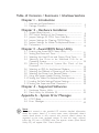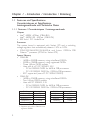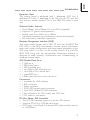
1
CB64-BX/ZX Rev. A+ System Board Carte Mère Manuel System-Platine Users Manual Pour Utilisateur Benutzerhandbuch 39700915 Copyright This publication contains information that is protected by copyright. No part of it may be reproduced in any form or by any means or used to make any transformation/ adaptation without the prior written permission from the copyright holders. This publication is provided for informational purposes only. The manufacturer makes no representations or warranties with respect to the contents or use of this manual and specifically disclaims any express or implied warranties of merchantability or fitness for any particular purpose. The user will assume the entire risk of the use or the results of the use of this document. Fur ther, the manufacturer reserves the right to revise this publication and make changes to its contents at any time, without obligation to notify any person or entity of such revisions or changes. © 1999. All Rights Reserved. Trademarks Microsoft® MS-DOS ®, WindowsTM, Windows® 95 and Windows® 98 are registered trademarks of Microsoft Corporation. Intel® and CeleronTM are registered trademarks of Intel Corporation. Award is a registered trademark of Award Software, Inc. Other trademarks and registered trademarks of products appearing in this manual are the properties of their respective holders. Caution: Danger of explosion if battery incorrectly replaced. Replace only with the same or equivalent type recommended by the manufacturer. Dispose of used batteries according to the battery manufacturers instructions. FCC and DOC Statement on Class B This equipment has been tested and found to comply with the limits for a Class B digital device, pursuant to Part 15 of the FCC rules. These limits are designed to provide reasonable protection against harmful interference when the equipment is operated in a residential installation. This equipment generates, uses and can radiate radio frequency energy and, if not installed and used in accordance with the instruction manual, may cause harmful interference to radio communications. However, there is no guarantee that interference will not occur in a particular installation. If this equipment does cause harmful interference to radio or television reception, which can be determined by turning the equipment off and on, the user is encouraged to try to correct the interference by one or more of the following measures: Reorient or relocate the receiving antenna. Increase the separation between the equipment and the receiver. Connect the equipment into an outlet on a circuit different from that to which the receiver is connected. Consult the dealer or an experienced radio TV technician for help. Notice: 1. The changes or modifications not expressly appro ved by the party responsible for compliance could void the user's authority to operate the equipment. 2. Shielded interface cables must be used in order to comply with the emission limits. Table of Contents / Sommaire / Inhaltsverzeichnis Chapter 1 - Introduction 1.1 Features and Specifications ................................................................. 1.2 Package Checklist ...................................................................................... Chapter 2 - Hardware Installation 2.1 2.2 2.3 2.4 2.5 2.6 System Board Layout ............................................................................. DIP Switch Settings of the Processors ...................................... Jumper Settings for CPUs Front Side Bus.............................. Jumper Settings for Clearing CMOS Data .............................. Jumper Settings for Wake-On-Keyboard/Mouse ................. Connectors ................................................................................................... Chapter 3 - Award BIOS Setup Utility 3.1 3.2 3.3 3.4 3.5 3.6 3.7 3.8 3.9 3.10 3.11 3.12 Entering the Award BIOS Setup Utility ..................................... Setting the Date and Time ................................................................. Selecting the Hard Drive and Floppy Drive Type .............. Selecting the Drive to be Searched First for an Operating System ..................................................................................... Selecting the External System Bus Clock of the Processor ....................................................................................................... Selecting an IRQ for the External Modem ............................. Selecting the Method of Powering-off the System............. Selecting the Power Lost Resume State ................................... Using the System Health Monitor Function ............................ Setting the Wake-On-Keyboard/Mouse Function ................ Loading Fail-Safe Settings/Optimal Settings .............................. Setting the Supervisor/User Password ...................................... Chapter 4 - Supported Softwares 4 7 8 10 11 12 13 14 21 22 23 24 25 29 30 31 33 35 39 39 4.1 Hardware Doctor Utility .................................................................... 41 4.2 Patch Utility for Windows 95 ......................................................... 42 Appendix A - System Error Messages A.1 POST Beep .................................................................................................. 43 A.2 Error Messages ........................................................................................... 43 Note: The users manual in the provided CD contains detailed information about the system board. If, in some cases, some information doesnt match those shown in this manual, this manual should always be regarded as the most updated version. To view the users manual, insert the CD into a CD-ROM drive. The autorun screen (Main Board Utility CD) will appear. Click Users Manual. Chapter 1 - Introduction / Introduction / Einleitung 1.1 Features and Specifications Caractéristiques et Spécifications Leistungsmerkmale und Technische Daten 1.1.1 Features / Caractéristiques / Leistungsmerkmale Chipset Intel 440BX AGPset (CB64-BX) Intel 440ZX-100 AGPset (CB64-ZX) ESS Solo-1 PCI AudioDrive Processor The system board is equipped with Socket 370 and a switching voltage regulator that automatically detects 1.30V to 2.05V. 300A/333/366/400/433/466MHz and future 100MHz FSB CeleronTM processor (PPGA for Socket 370) System Memory CB64-BX - 16MB to 384MB memory using unbuffered DIMMs - 32MB to 768MB memory using registered DIMMs - Three 168-pin DIMM sockets - Uses x64 or x72 PC SDRAM, 3.3V : PC-66 SDRAM DIMM for 66MHz FSB processors : PC-100 SDRAM DIMM for 100MHz FSB processors - ECC supported (uses x72 PC SDRAM DIMM) CB64-ZX - 16MB to 256MB memory using unbuffered DIMMs - Two 168-pin DIMM sockets - Uses x64 PC SDRAM, 3.3V : PC-66 SDRAM DIMM for 66MHz FSB processors : PC-100 SDRAM DIMM for 100MHz FSB processors DIMMs Memory Size 2MBx64/x72 16MB 4MBx64/x72 32MB 64MB 8MBx64/x72 16MBx64/x72 128MB 32MBx64/x72 256MB* CB64-BX * Supported only when CB64-BX uses registered DIMMs. 4 Memory Size DIMMs 16MB 2MBx64 4MBx64 32MB 8MBx64 64MB 16MBx64 128MB CB64-ZX Introduction Expansion Slots The system board is equipped with 1 dedicated AGP slot, 4 dedicated PCI slots, 2 dedicated 16-bit ISA slot. All PCI and ISA slots are bus masters except PCI4 in the CB64-ZX which is slave only. Onboard Audio Features Sound Blaster, Sound Blaster Pro and WSS compatible Supports PC games and applications Sample rates from 4KHz up to 48KHz Full duplex operation for simultaneous record and playback ESS proprietary AudioRack application Desktop Management Interface (DMI) The system board comes with a DMI 2.0 built into the BIOS. The DMI utility in the BIOS automatically records various information about your system configuration and stores these information in the DMI pool, which is a part of the system board's Plug and Play BIOS. DMI, along with the appropriately networked software, is designed to make inventory, maintenance and troubleshooting of computer systems easier. ATX Double Deck Ports 2 USB ports 2 DB-9 serial ports 1 DB-25 parallel port 1 mini-DIN-6 PS/2 keyboard port 1 mini-DIN-6 PS/2 mouse port 1 game/MIDI port 3 audio jacks: line-out, line-in and mic-in Connectors 1 connector for IrDA interface 2 IDE connectors 1 floppy connector 1 20-pin ATX power supply connector 1 3-pin WOL (Wake-On-LAN) connector 3 fan connectors for CPU, chassis and AGP fans 3 CD audio-in connectors PCI Bus Master IDE Controller Two PCI IDE interfaces support up to four IDE devices Supports ATA/33 or ATA/66 hard drives PIO Mode 3 and Mode 4 Enhanced IDE (data transfer rate up to 16.6MB/sec.) 5 1 1 Introduction Bus mastering reduces CPU utilization during disk transfer ATAPI CD-ROM, LS-120 and ZIP supported IrDA Interface The system board is equipped with an IrDA connector for wireless connectivity between your computer and peripheral devices. It supports peripheral devices that meet the IrDA or ASKIR standard. USB Ports The system board is equipped with two USB ports. USB allows data exchange between your computer and a wide range of simultaneously accessible external Plug and Play peripherals. BIOS Award BIOS, Windows 95/98 Plug and Play compatible Supports SCSI sequential boot-up Flash EPROM for easy BIOS upgrades Includes NCR 810 SCSI BIOS 2MB flash memory 1.1.2 Intelligence / Intelligence / Intelligente Ausstattungsteile Automatic CPU/Chassis Fan Off The CPU and chassis fans will automatically turn off once the system enters the Suspend mode. Dual Function Power Button Depending on the setting in the BIOS setup, this switch will allow your system to enter the Soft-Off or Suspend mode. External Modem Ring-on The Modem Ring-on feature allows the system that is in the Suspend mode or Soft Power Off mode to wake-up/power-on to respond to incoming calls. This feature supports external modem only. RTC Timer to Power-On the System The RTC installed on the system board allows your system to automatically power-on on the set date and time. Wake-On-LAN Ready The Wake-On-LAN function allows the network to remotely wake up a Soft Power Down (Soft-Off) PC. Your LAN card must support the remote wakeup function. Important: The 5VSB power source of your power supply must support ≥720mA (minimum). 6 Introduction Wake-On-Keyboard/Wake-On-Mouse This function allows you to use the keyboard or mouse to poweron the system. Refer to sections 2.5 (chapter 2) and 3.10 (chapter 3) for more information. Important: The power button will not function once a keyboard password has been set in the KB Power On Password field of the Integrated Peripherals setup. You must type the correct password to power-on the system. The 5VSB power source of your power supply must support ≥720mA (minimum). ACPI The system board is designed to meet the ACPI (Advanced Configuration and Power Interface) specification. ACPI has energy saving features that enables PCs to implement Power Management and Plug-and-Play with operating systems that support OS Direct Power Management. Virus Protection Most viruses today destroy data stored in hard drives. The system board is designed to protect the boot sector and partition table of your hard disk drive. 1.2 Package Checklist Liste de Vérification de lEmballage Verpackungsliste The system board package contains the following items: The system board A users manual One 40-pin IDE hard disk cable One 34-pin floppy disk drive cable One CD If any of these items are missing or damaged, please contact your dealer or sales representative for assistance. 7 1 Chapter 2 - Hardware Installation Installation du Matériel Installation der Hardware 2.1 System Board Layout Position de la Carte Système Aufbau der Hauptplatine CB64-BX 8 Hardware Installation 2 CB64-ZX Note: The illustrations on the following pages are based on the CB64-BX system board, which is the board equipped with three DIMM sockets. 9 2 Hardware Installation 2.2 DIP Switch Settings for Processors Positionnement des Cavaliers des Processeurs DIP Schaltereinstellungen für den Prozessor Note: SW1 is for factory use only. In the example above: Switch Switch Switch Switch Processor Processor 66MHz 100MHz Frequency Ratio 4.5x 433MHz Future processor 6.5x Future processor 5x 466MHz Future processor 7x 366MHz Future processor 5.5x Future processor Future processor 7.5x 400MHz Future processor 6x Future processor Future processor 8x 66MHz 100MHz 300MHz (300A) Future processor 333MHz Frequency Ratio 1: Off 2: On 3: Off 4: On SW1 SW1 Note: 1. Intel Celeron TM processors (PPGA) suppor t VID (Voltage Identification). The switching voltage regulator on the system board will automatically set the voltage regulator according to the voltage of the processor. 2. You cannot overclock an Intel CeleronTM processor (PPGA) because its frequency ratio has been fixed by the manufacturer. The table above is for factory use only. 10 Hardware Installation 2 2.3 Jumper Settings for the CPUs Front Side Bus Positionnement des Cavaliers pour le Bus Frontal du Processeur Jumpereinstellungen fuer CPU Vorderseitenbus Jumper JP2 - CPUs Front Side Bus Select The default setting of jumper JP2 is Auto - the system will automatically run according to the FSB of the processor. The 100MHz setting (12-3 Off) is reser ved for future 100MHz FSB processors. Refer to the figure below. Warning: If your system is installed with a 66MHz FSB processor, do not move the jumper cap from its default setting which is pins 1 and 2 On; otherwise your system will not boot. 1 1 1 2 2 2 3 3 3 1-2 On: Auto (default) 2-3 On: 66MHz 1-2-3 Off: 100MHz 11 2 Hardware Installation 2.4 Jumper Settings for Clearing CMOS Data Positionnement des Cavaliers pour Effacer les Données CMOS Jumpereinstellungen zum Löschen der CMOS Daten Jumper JP3 - CMOS Clear To load the default values stored in the ROM BIOS, please follow the steps below. 1. Power-off the system and unplug the power cord. 2. Set JP3 pins 2 and 3 to On. Wait for a few seconds and set JP3 back to its default setting, pins 1 and 2 On. 3. Plug the power cord and poweron the system. 1 1 2 2 3 3 1-2 On: Normal (default) 12 2-3 On: Clear CMOS Data Hardware Installation 2 2.5 Jumper Settings for Wake-On-Keyboard/Mouse Positionnement des Cavaliers pour Réveil-Sur-Clavier/ Souris Jumpereinstellungen für die Wake-On Tastatur/Maus Jumper JP1 - Wake-on-Keyboard/Mouse To use the keyboard or mouse to power-on the system, please follow the steps below. 1. Set JP1 to 2-3 On, enable. 2. Keyboard/Mouse Power On in the Integrated Peripherals setup of the Award BIOS must be set accordingly. Refer to section 3.10 (chapter 3) for more information. 1 2 3 1-2 On: Disable (default) 1 2 3 2-3 On: Enable Warning: 1. If JP1 was previously enabled with a password set in the KB Power On Password field, and now you wish to disable the Wake-On-Keyboard (password) function, make sure to set the Keyboard/Mouse Power On field to Disabled prior to setting JP1 to disabled. You will not be able to boot up the system if you fail to do so. 2. The power button will not function once a keyboard password has been set in the KB Power On Password field of the Integrated Peripherals setup. You must type the password to power-on the system. 3. The 5VSB power source of your power supply must support ≥720mA (minimum). 13 2 Hardware Installation 2.6 Connectors / Connecteurs / Anschlüsse 2.6.1 Floppy Disk Drive Controller and IDE Interface Contrôleur de Lecteur de Disquette et Interface IDE Diskettenlaufwerkcontroller und IDE Interface Important: If you encountered problems while using an ATAPI CD-ROM drive that is set in Master mode, please set the CD-ROM drive to Slave mode. Some ATAPI CD-ROMs may not be recognized and cannot be used if incorrectly set in Master mode. 2.6.2 IrDA Connector Connecteur IrDA IrDA Anschlüsse 14 Pin Function 1 IRTX 2 GND 3 IRRX 4 N. C. 5 VCC Hardware Installation 2 2.6.3 CPU Fan Connector Connecteur du Ventilateur de CPU CPU Kühlung Anschluß Pin Function 1 On/Off 2 +12V 3 Sense 2.6.4 Chassis Fan Connector Connecteur de Châssis de Ventilateur Anschluß Kühlungsgehäuse Pin Function 1 On/Off 2 +12V 3 Sense 15 2 Hardware Installation 2.6.5 AGP Fan Connector Connecteur de Ventilateur AGP Anschluß AGP Kühlung Pin Function 1 Ground 2 +12V 3 N. C. 2.6.6 CD Audio-in Connector Connecteur dEntrée Audio CD CD Audio-in Anschluß J22/J23 J21 16 Pin J23 - Mitsumi J22 - Sony J21 - Sony 1 CD-L CD-L CD-L 2 CD-G CD-G CD-G 3 CD-R CD-G CD-G 4 CD-G CD-R CD-R Hardware Installation 2 Connect the CD audio cable to J23 (Mitsumi CD-ROM) or J22 (Sony CD-ROM) if the audio cable included in your CD-ROM package should look somewhat similar to the one on the right. Connect the CD audio cable to J21 (Sony CD-ROM) if the audio cable included in your CD-ROM package should look somewhat similar to the one on the right. 2.6.7 Wake-On-LAN (WOL) Connector Connecteur Réveil-Sur-LAN (WOL) Wake-On-LAN (WOL) Anschluß Pin Function 1 +5VSB (720mA) 2 Ground 3 WOL Important: The 5VSB power source of your power supply must support ≥720mA (minimum). 17 2 Hardware Installation 2.6.8 LEDs and Switches Commutateurs et LED LEDs und Schalter 18 Hardware Installation HD-LED (Primary/Secondar y IDE LED) G-LED (Green LED) ATX-SW (ATX power switch) G-SW (Green switch) RESET (Reset switch) SPEAKER (Speaker connector) KEYLOCK (Keylock and Power LED connector) Pin 1 2 3 4 5 6 7 8 9 10 11 12 13 14 15 16 17 18 19 20 21 22 23 24 25 2 Pin Assignment HDD LED Power HDD N. C. Green LED Power Green N. C. PWRBT Ground N. C. SMI Ground N. C. H/W Reset Ground N. C. Speaker Data N. C. Ground Speaker Power N. C. LED Power N. C. Standby Signal Keylock Ground Use pins 21 to 23 for the Power/ Standby LED. Important: ATX-SW (ATX Power Switch) - Depending on the setting in the BIOS setup, this switch is a dual function power button that will allow your system to enter the Soft-Off or Suspend mode. Refer to section 3.7 (chapter 3) for more information. 19 2 Hardware Installation 2.6.9 Power Connector Connecteur dAlimentation Netzanschluß PS1 connectors pin assignment. Pin Function Pin Function 1 3.3V/14A 11 3.3V/14A 2 3.3V/14A 12 -12V 3 COM 13 COM 4 +5V 14 PS-ON 5 COM 15 COM 6 +5V 16 COM 7 COM 17 COM 8 PW-OK 18 -5V 9 5VSB 19 +5V 10 +12V 20 +5V Important: Your power supply must meet the ATX specification - supporting 3.3V/14A (minimum), otherwise your system will not boot properly. 20 Chapter 3 - Award BIOS Setup Utility Utilitaire de Configuration du Award BIOS AWARD BIOS Konfigurationsprogramm 3.1 Entering the Award BIOS Setup Utility Entrer Dans lUtilitaire de Configuration du Award BIOS Aufruf des AWARD BIOS Konfigurationsprogramms Power-on the system and press <Del> to enter the utility. The main program screen will appear. Allumez le Système et appuyez sur <Del> pour entrer dans lutilitaire. Lécran du programme principal apparaîtra. Zum Aufrufen des Konfigurationsprogramms drücken Sie während des Startvorgangs die Taste <Del>. Ein Bildschirm ähnlich dem folgenden erscheint. ROM PCI/ISA BIOS CMOS SETUP UTILITY AWARD SOFTWARE, INC. STANDARD CMOS SETUP BIOS FEATURES SETUP CHIPSET FEATURES SETUP POWER MANAGEMENT SETUP PNP/PCI CONFIGURATION LOAD FAIL-SAFE SETTINGS LOAD OPTIMAL SETTINGS Esc F10 : Quit : Save & Exit Setup INTEGRATED PERIPHERALS SUPERVISOR PASSWORD USER PASSWORD IDE HDD AUTO DETECTION SAVE & EXIT SETUP EXIT WITHOUT SAVING ↑↓→← (Shift) F2 : Select Item : Change Color 21 3 Award BIOS Setup Utility 3.2 Setting the Date and Time Paramétrage de la Date et de lHeure Einstellen des Datums und der Zeit ROM PCI/ISA BIOS STANDARD CMOS SETUP AWARD SOFTWARE, INC. Date (mm:dd:yy) : Fri, Mar 5 1999 Time (hh:mm:ss) : 13: 27: 50 HARD DISKS Primary Master : Primary Slave : Secondary Master : Secondary Slave : TYPE SIZE CYLS HEAD Auto 0 0 0 Auto 0 0 0 Auto 0 0 0 Auto 0 0 0 PRECOMP LANDZ SECTOR MODE 0 0 0 Auto 0 0 0 Auto 0 0 0 Auto 0 0 0 Auto Drive A : 1.44M, 3.5 in. Drive B : None Base Memory : 640K Extended Memory : 64512K Other Memory : 384K Total Memory : 65536K Video : EGA/VGA Halt on : All Errors Esc F10 : Quit : Save & Exit Setup ↑↓→← (Shift)F2 : Select Item : Change PU/PD/+/- : Modify 1. Select Standard CMOS Setup in the main program screen and press <Enter>. Sélectionnez Standard CMOS Setup dans lécran du programme principal et appuyez sur <Entrée>. Standard CMOS Setup in dem Hauptbildschirm auswählen, und die Eingabetaste (Enter) drücken. 2. Set the correct date and time in the Date and Time fields respectively. Sélectionnez la date et lheure correcte dans les champs Date et Time respectivement. Jeweils korrekte Wer te in die Eingabefelder Date (Datum) und Time (Zeit) eingeben. 22 Award BIOS Setup Utility 3 3.3 Selecting the Hard Drive and Floppy Drive Type Sélectionnez le Type de Disque Dur et de Lecteur de Disquette Auswahl der Festplatte und des Diskettenlaufwerks ROM PCI/ISA BIOS STANDARD CMOS SETUP AWARD SOFTWARE, INC. Date (mm:dd:yy) : Fri, Mar 5 1999 Time (hh:mm:ss) : 13: 27: 50 HARD DISKS Primary Master Primary Slave Secondary Master Secondary Slave TYPE SIZE CYLS HEAD : Auto 0 0 0 0 0 : Auto 0 : Auto 0 0 0 : Auto 0 0 0 PRECOMP LANDZ SECTOR MODE 0 0 Auto 0 0 0 0 Auto 0 0 0 Auto 0 0 0 Auto Drive A : 1.44M, 3.5 in. Drive B : None Base Memory : 640K Extended Memory : 64512K Other Memory : 384K Total Memory : 65536K Video : EGA/VGA Halt on : All Errors Esc F10 : Quit : Save & Exit Setup ↑↓→← (Shift)F2 : Select Item : Change PU/PD/+/- : Modify 1. Select Standard CMOS Setup in the main program screen and press <Enter>. Sélectionnez Standard CMOS Setup dans lécran du programme principal et appuyez sur <Entrée>. Standard CMOS Setup in dem Hauptbildschirm auswählen, und die Eingabetaste (Enter) drücken. 2. Select Auto for the hard disk drive(s) installed in your system. The BIOS will auto-detect the HDD & CD-ROM drive at the POST stage and show the IDE for the HDD & CD-ROM drive. If a hard disk has not been installed, select None and press <Enter>. Sélectionnez Auto pour le(s) disque(s) dur(s) installés dans votre système. Le BIOS détectera automatiquement le Disque Dur et le Lecteur CD-ROM durant la phase POST et affichera lIDE du Disque Dur et du Lecteur CD-ROM. Si aucun disque dur na été installé, sélectionnez None et appuyez sur <entrée>. Im Eintrag Hard Disk Drive(s) (Festplatte) Auto auswählen. Das Programm entdeckt die Festplatte sowie das CD-ROM Laufwerk während der Initialisierung automatisch. Ist keine Festplatte installier t, aktivieren Sie den Eintr ag None. Eingabetaste (Enter) drücken. 23 3 Award BIOS Setup Utility 3. Set the type of floppy drive installed in the Drive A and Drive B fields. The options are None, 360K, 1.2M, 720K, 1.44M and 2.88M. Paramétrez le type de lecteur de disquette installé dans les champs Drive A et Drive B. Les options sont None, 360K, 1.2M, 720K, 1.44M et 2.88M. Im Eintrag Floppy Drive (Diskettenlaufwerk) wählen Sie Drive A (Laufwerk A) und Drive B (Laufwerk B). Die Optionen sind None (Kein), 360K, 1.2M, 720K, 1.44M und 2.88M. 3.4 Selecting the Drive to be Searched First for an Operating System Sélectionner le Lecteur qui doit être Détecté en premier par un Système dExploitation Auswahl des Bootlaufwerks ROM PCI/ISA BIOS BIOS FEATURES SETUP AWARD SOFTWARE, INC. Virus Warning CPU L1 Cache CPU L2 Cache CPU L2 Cache ECC Checking Quick Power On Self Test Boot Sequence Swap Floppy Drive Boot Up Floppy Seek Boot Up NumLock Status Typematic Rate Setting Typematic Rate (Chars/Sec) Typematic Delay (Msec) Security Option PCI/VGA Palette Snoop OS Select For DRAM > 64MB HDD S.M.A.R.T. Capability : : : : : : : : : : : : : : : : Disabled Enabled Enabled Enabled Enabled A, C, SCSI Disabled Disabled On Disabled 6 250 Setup Disabled Non-OS2 Disabled ESC F1 F5 F6 F7 : : : : : ↑↓→← Quit : Select Item Help PU/PD/+/- : Modify Old Values (Shift) F2 : Color Load Fail-Safe Settings Load Optimal Settings 1. Select BIOS Features Setup in the main program screen and press <Enter>. Sélectionnez BIOS Features Setup dans lécran de programme principal et appuyez sur <Entrée>. BIOS Features Setup in dem Hauptbildschirm auswählen, und die Eingabetaste (Enter) drücken. 2. Select the drive to be searched first in the Boot Sequence field. The default is A, C, SCSI. The other options are: C, A, SCSI; C, CDROM, A; CDROM, C, A; D, A, SCSI; E, A, SCSI; F, A, SCSI; SCSI, A, C; SCSI, C, A; C only and LS/ZIP, C. 24 Award BIOS Setup Utility 3 Sélectionnez le lecteur qui devra être détecté en premier dans le champs Boot Sequence. La valeur par défaut est A, C, SCSI. Les autres options sont: C, A, SCSI; C, CDROM, A; CDROM, C, A; D, A, SCSI; E, A, SCSI; F, A, SCSI; SCSI, A, C; SCSI, C , A; C seulement et LS/ZIP, C. Im Boot Sequence Feld wählen Sie die Sequenz, in welcher der Computer nach einem Betriebssystem sucht. Die Optionen sind C, A, SCSI; C, CDROM, A; CDROM, C, A; D, A, SCSI; E, A, SCSI; F, A, SCSI; SCSI, A, C; SCSI, C, A; nur C und LS/ZIP, C . 3.5 Selecting the External System Bus Clock of the Processor Paramétrage de lHorloge Externe de Bus Système du Processeur Auswahl des externen Systemtaktgebers Ihres Prozessors ROM PCI/ISA BIOS CHIPSET FEATURES SETUP AWARD SOFTWARE, INC. SDRAM RAS-to-CAS Delay SDRAM RAS Precharge Time SDRAM CAS Latency Time SDRAM Precharge Control DRAM Data Integrity Mode System BIOS Cacheable Video BIOS Cacheable Video RAM Cacheable 8 Bit I/O Recovery Time 16 Bit I/O Recovery Time Memory Hole At 15M-16M PCI 2.1 Compliance AGP Aperture Size (MB) CPU/PCI Clock (MHz) Spread Spectrum : : : : : : : : : : : : : : : 3 3 3 Disabled Non-ECC Disabled Disabled Disabled 1 1 Disabled Disabled 64 Default Disabled **** System Health Monitor **** : 28o C/82oF Current System Temp. Current CPU Temperature : 42oC/107oF 0 RPM Current Chassis FAN Speed : : 4326 RPM Current CPU FAN Speed CPU(V) : 2.00 V : 1.51 V +1.5 V : 3.40 V +3.3 V +5 V : 5.08 V : 12.34 V +12 V : -11.76 V -12 V : -5.09 V -5 V ESC F1 F5 F6 F7 : : : : : Quit ↑ ↓ → ← : Select Item Help PU/PD/+/- : Modify Old Values (Shift) F2 : Color Load Fail-Safe Settings Load Optimal Settings 25 3 Award BIOS Setup Utility 1. Select Chipset Features Setup in the main program screen and press <Enter>. Sélectionnez Chipset Features Setup dans lécran de programme principal et appuyez sur <Entrée>. Chipset Features Setup in dem Hauptbildschirm auswählen, und die Eingabetaste (Enter) drücken. 2. Select the external system bus clock of your processor in the CPU/PCI Clock (MHz) field. The options are Default, 66.8/33.4, 75/37.5, 83.3/41.65, 100.3/33.4, 103/34.33, 105/35, 110/36.67, 112/37.33, 115/38.33, 120/40, 124/31, 124/41.33, 133/33.25, 133/44.33, 140/35 and 150/37.5. When selecting the external bus clock of your processor, the PCI clock will at the same time appear next to the external bus clock selected. For example, if you selected 66.8/33.4, 66.8MHz is the external bus clock and 33.4MHz is the PCI clock. Regardless of the type of processor used, the default setting is Default. Under this setting, the system will run according to the processors clock frequency. If you selected an option other than Default and is unable to boot up the system, there are 2 methods of going back to its default setting. Method 1: Clear the CMOS data by following the procedure in section 2.4 (chapter 2) of this manual. All fields in the BIOS Setup will automatically be set to its default settings. Method 2: Press the <Inser t> key and power b utton simultaneously, then release the power button first. You must keep-on pressing the <Inser t> key until the power-on screen appears. This will allow the system to boot according to the FSB of the processor. Now press the <Del> key to enter the Award BIOS setup utility. Select Chipset Features Setup and set the CPU/PCI Clock (MHz) field to Default or an appropriate clock frequency. Note: When using a 66MHz FSB processor, the AGP clock and the CPUs external bus clock are similar. When using a 100MHz FSB processor, the AGP clock is 2/3 of the CPUs external bus clock. 26 Award BIOS Setup Utility 3 Sélectionnez lHorloge Externe de Bus Système de votre processeur dans le champ CPU/PCI Clock (MHz). Les options par Default, 66.8/33.4, 75/37.5, 83.3/41.65, 100.3/33.4, 103/ 34.33, 105/35, 110/36.67, 112/37.33, 115/38.33, 120/40, 124/ 31, 124/41.33, 133/33.25, 133/44.33, 140/35 et 150/37.5. Lhorloge PCI apparaîtra simultanément à côté de lhorloge bus externe en sélectionnant lhor loge bus externe de votre processeur. Si, par exemple, on sélectionne 66.8/33.4, lhorloge bus externe sera 66.8MHz et lhorloge PCI sera 33.4MHz. Indépendamment du type de processeur utilisé, le paramètre par défaut est Default. Avec ces paramètres, le système fonctionnera dune manière qui correspond à la fréquence dhorloge du processeur. Si vous sélectionnez une option autre que Default et que vous ne puissiez pas amorcer le système, il existe 2 méthodes pour rétablir les paramètres par défaut. Méthode 1: Effacez les données du CMOS en suivant la procédure décrite dans la Section 2.4 (Chapitre 2) de ce manuel. Tous les champs dans le programme dinstallation du BIOS seront positionnés automatiquement à leur valeur par défaut. Méthode 2: Appuyez sur la touche <Insert> et le bouton de mise sous tension simultanément, puis relâchez tout dabord le bouton de mise sous tension. Vous devez continuer à appuyer sur la touche <Inser t> jusquà ce que lécran de mise en route apparaisse. Ceci permettra au système de redémarrer en fonction du FSB du processeur. Maintenant appuyez sur la touche <Del> afin dentrer dans lutilitaire dinstallation du Award BIOS. Sélectionnez Chipset Features Setup et positionnez le champ CPU/PCI Clock (MHz) sur Default ou sur la fréquence dhorloge qui convient. Note: Lhorloge AGP et lhorloge bus externe du CPU sont presquement pareilles en utilisant un processeur FSB à 66MHz. Si on travaille avec un processeur FSB à 100MHz, lhorloge AGP sera 2/3 de lhorloge bus externe du CPU. 27 3 Award BIOS Setup Utility Im CPU/PCI Clock (MHz) Feld sind folgende. Sind die Optionen Default, 66.8/33.4, 75/37.5, 83.3/41.65, 100.3/33.4, 103/34.33, 105/35, 110/36.67, 112/37.33, 115/38.33, 120/40, 124/31, 124/41.33, 133/33.25, 133/44.33, 140/35 und 150/ 37.5. Beim Auswählen des externen Bus-Taktgeber s Ihres Prozessors erscheint der PCI-Taktgeber gleichzeitig neben dem ausgewählten externen Bus-Taktgeber. Wählen Sie beispielsweise 66.8/33.4 aus, beträgt der externe Bus-Taktgeber 66.8MHz und der PCI-Taktgeber 33.4MHz. Die Standardeinstellung ist auf Default eingestellt, ungeachtet des Prozessor typs, mit dem Sie arbeiten. Bei dieser Einstellung funktioniert das System gemäß der Taktfrequenz des Prozessors. Wählen Sie eine andere Option als Default aus und das System kann damit nicht gestartet werden, gibt es zwei Methoden, die Standardeinstellung wiederherzustellen. Methode 1: Die CMOS-Daten müssen durch Befolgen des in Abschnitt 2.4 (Kapitel 2) in diesem Handbuch beschriebenen Vorgangs gelöscht werden. Sämtliche Bereiche im BIOS-Setup werden dann automatisch auf ihre Standardeinstellung eingestellt. Methode 2: Die Taste <Insert> und die Netztaste gleichzeitig drücken. Dann zuerst die Netztaste loslassen, aber die Taste <Insert> solange gedrückt halten, bis der Einschalt-Schirm erscheint. Dies ermöglicht ein Star ten des Systems gemäß dem FSB des Prozessors. Zum Aktivieren des Dienstprogramms des Award-BIOS-Setup muß die <Del>-Taste gedrückt werden. Dann Chipset Features Setup auswählen und die CPU/PCI Clock (MHz) auf Default pder eine geeignete Taktfrequenz einstellen. Hinweis: Beim Betrieb mit einem 66MHz-FSB-Prozessor sind der AGP-Taktgeber und der externe BusTaktgeber des CPUs ähnlich. Der AGP-Taktgeber beträgt 2/3 des externen Bus-Taktgeber s des CPUs, falls ein 100MHz-FSB-Prozessor verwendet wird. 28 Award BIOS Setup Utility 3 3.6 Selecting an IRQ for the External Modem Sélectionner une IRQ pour le Modem Externe IRQ Bestimmung für ein externes Modem ROM PCI/ISA BIOS POWER MANAGEMENT SETUP AWARD SOFTWARE, INC. ACPI Function Power Management PM Control by APM Video Off Method Video Off After MODEM Use IRQ Standby Mode Suspend Mode HDD Power Down PCI/VGA Act-Monitor Soft-Off by PWR-BTTN PWR Lost Resume State Resume on Ring Resume on LAN Resume on Alarm : : : : : : : : : : : : : : : Disabled User Define Yes DPMS Suspend 3 Disabled Disabled Disabled Disabled Instant-Off Keep Off Disabled Disabled Disabled ESC F1 F5 F6 F7 : : : : : Quit ↑ ↓ → ← : Select Item Help PU/PD/+/- : Modify Old Values (Shift) F2 : Color Load Fail-Safe Settings Load Optimal Settings 1. Select Power Management Setup in the main program screen and press <Enter>. Sélectionnez Power Management Setup dans lécran de programme principal et appuyez sur <Entrée>. Power Management Setup in dem Hauptbildschirm auswählen, und die Eingabetaste (Enter) drücken. 2. Select an IRQ for the external modem in the MODEM Use IRQ field. The options are IRQ 3, 4, 5, 7, 9, 10 or 11. You need to select an IRQ only if you are using the modem ring-on function. Sélectionnez une IRQ pour le modem externe dans le champ MODEM Use IRQ Les options sont IRQ 3, 4, 5, 7, 9, 10 ou 11. Vous devez sélectionner une seule IRQ seulement si vous utilisez la fonction de sonnerie du modem. In dem Feld MODEM Use IRQ eine entsprechende IRQBestimmung für das externen Modem vornehmen. Die Optionen sind IRQ 3, 4, 5, 7, 9, 10 und 11. Eine Einstellung ist nur dann nötig, wenn bestimmte Funktionen (ring-on) des Modems benutzt werden sollen. 29 3 Award BIOS Setup Utility 3.7 Selecting the Method of Powering-off the System Sélection de la Méthode pour Eteindre le Système Auswahl der Abschaltmethode ROM PCI/ISA BIOS POWER MANAGEMENT SETUP AWARD SOFTWARE, INC. ACPI Function Power Management PM Control by APM Video Off Method Video Off After MODEM Use IRQ Standby Mode Suspend Mode HDD Power Down PCI/VGA Act-Monitor Soft-Off by PWR-BTTN PWR Lost Resume State Resume on Ring Resume on LAN Resume on Alarm : : : : : : : : : : : : : : : Disabled User Define Yes DPMS Suspend 3 Disabled Disabled Disabled Disabled Instant-Off Keep Off Disabled Disabled Disabled ESC F1 F5 F6 F7 : : : : : Quit ↑ ↓ → ← : Select Item Help PU/PD/+/- : Modify Old Values (Shift) F2 : Color Load Fail-Safe Settings Load Optimal Settings 1. Select Power Management Setup in the main program screen and press <Enter>. Sélectionnez Power Management Setup dans lécran de programme principal et appuyez sur <Entrée>. Power Management Setup in dem Hauptbildschirm auswählen, und die Eingabetaste (Enter) drücken. 2. Select the method of powering-off the system in the Soft-Off by PWR-BTTN field. The options are Hold 4 Sec. and Instant-Off. Sélectionnez la Méthode pour éteindre le système dans le champ Soft-Off by PWR-BTTN. Les options sont Hold 4 Sec. et Instant-Off. In dem Feld Soft-Off by PWR-BTTN können Sie die Methode bestimmen, mit welcher Ihr Rechner ausgeschaltet wird. Die Optionen sind Hold 4 Sec. (4 Sekunden warten) und Instant-Off (Direktabschaltung). Hold 4 Sec. If the power button is pushed and released in less than 4 seconds, the system enters the Suspend mode. Push and release it again in less than 4 seconds to restore. Pushing the power button for more than 4 seconds will power-off the system. 30 Award BIOS Setup Utility 3 Si le bouton de mise sous tension est poussé puis relâché en moins de 4 secondes, le système entrera en mode suspend. Poussez le et relâchez le à nouveau en moins de 4 secondes pour restaurer la fonction. Le fait dappuyer sur le bouton de mise sous tension pendant plus de 4 secondes éteindra le système. Wird die Netztaste gedrückt und innerhalb von 4 Sekunden wieder losgelassen, schaltet sich das System in den Suspend-Modus. Ein erneutes Drücken mit einem Loslassen innerhalb von 4 Sekunden stellt den Normalzustand wieder her. Wird die Netztaste für die Dauer von über 4 Sekunden gedrückt gehalten, schaltet sich das System ab. Instant-Off Pressing and then releasing the power button at once will immediately power-off the system. Le fait dappuyer sur le bouton de mise sous tension en une fois éteindra le système immédiatement. Normales Drücken der Netztaste schaltet das System augenblicklich ab. 3.8 Selecting the Power Lost Resume State Choisir létat de Redémarrage Après Coupure de Courant Auswaehlen des PWR Lost Resume Status ROM PCI/ISA BIOS POWER MANAGEMENT SETUP AWARD SOFTWARE, INC. ACPI Function Power Management PM Control by APM Video Off Method Video Off After MODEM Use IRQ Standby Mode Suspend Mode HDD Power Down PCI/VGA Act-Monitor Soft-Off by PWR-BTTN PWR Lost Resume State Resume on Ring Resume on LAN Resume on Alarm : : : : : : : : : : : : : : : Disabled User Define Yes DPMS Suspend 3 Disabled Disabled Disabled Disabled Instant-Off Keep Off Disabled Disabled Disabled ESC F1 F5 F6 F7 : : : : : Quit ↑ ↓ → ← : Select Item Help PU/PD/+/- : Modify Old Values (Shift) F2 : Color Load Fail-Safe Settings Load Optimal Settings 31 3 Award BIOS Setup Utility 1. Select Power Management Setup in the main program screen and press <Enter>. Sélectionnez Power Management Setup dans lécran de programme principal et appuyez sur <Entrée>. Power Management Setup in dem Hauptbildschirm auswählen, und die Eingabetaste (Enter) drücken. 2. Select the PWR Lost Resume State field. The options are: Sélectionnez PWR Lost Resume State. Les options sont In dem Feld PWR Lost Resume State. Die Optionen sind: Keep Off When power returns after an AC power failure, the systems power is off. You must press the Power button to power-on the system. Quand lalimentation revient après une coupure dalimentation C A, le système est éteint. Vous devez appuyer sur linterrupteur dAlimentation pour allumer le système. Beim Wiederherstellen der Stromversorgung nach einem Wechselstromausfall wird der Betrieb des Systems ausgeschaltet. Drücken Sie auf die Netztaste, um das System einzuschalten. Turn On When power returns after an AC power failure, the system will automatically power-on. Quand lalimentation revient après une coupure dalimentation C A, le système sallumer a automatiquement. Beim Wiederherstellen der Stromversorgung nach einem Wechselstromausfall wird das System automatisch eingeschaltet. Last State When power returns after an AC power failure, the system will return to the state where you left off before power failure occurs. If the systems power is off when AC power failure occurs, it will remain off when power returns. If the systems power is on when AC power failure occurs, the system will power-on when power returns. Quand lalimentation revient après une coupure dalimentation C A, le système retournera à létat 32 Award BIOS Setup Utility 3 où vous lavez laissé avant la coupure dalimentation. Si le système est éteint quand la coupure dalimentation CA se produit, il restera éteint lorsque le courant sera rétabli. Si le système est allumé quand la coupure dalimentation se produit, le système sallumera lorsque le courant sera rétabli. Beim Wiederherstellen der Stromversorgung nach einem Wechselstromausfall kehr t das System in den Status zurück, in welchem es sich beim Auftreten des Stromausfalles befand. Falls das System beim Auftreten des Stromausfalles ausgeschaltet war, wird das System beim Wiederher stellen der Stromver sorgung nicht eingeschaltet. Falls die Stromver sor gung des Systems beim Auftreten des Wechselstromausfalles eingeschaltet war, wird es beim Wiederherstellen der Stromversorgung eingeschaltet. 3.9 Using the System Health Monitor Function Utilisez de System Health Monitor Arbeiten der System Health Monitor ROM PCI/ISA BIOS CHIPSET FEATURES SETUP AWARD SOFTWARE, INC. SDRAM RAS-to-CAS Delay SDRAM RAS Precharge Time SDRAM CAS Latency Time SDRAM Precharge Control DRAM Data Integrity Mode System BIOS Cacheable Video BIOS Cacheable Video RAM Cacheable 8 Bit I/O Recovery Time 16 Bit I/O Recovery Time Memory Hole At 15M-16M PCI 2.1 Compliance AGP Aperture Size (MB) CPU/PCI Clock (MHz) Spread Spectrum : : : : : : : : : : : : : : : 3 3 3 Disabled Non-ECC Disabled Disabled Disabled 1 1 Disabled Disabled 64 Default Disabled **** System Health Monitor **** Current System Temp. : 28o C/82oF Current CPU Temperature : 42oC/107oF 0 RPM Current Chassis FAN Speed : : 4326 RPM Current CPU FAN Speed CPU(V) : 2.00 V : 1.51 V +1.5 V +3.3 V : 3.40 V : 5.08 V +5 V : 12.34 V +12 V : -11.76 V -12 V : -5.09 V -5 V ESC F1 F5 F6 F7 : : : : : ↑ ↓ → ← : Select Item Quit Help PU/PD/+/- : Modify Old Values (Shift) F2 : Color Load Fail-Safe Settings Load Optimal Settings 1. Select Chipset Features Setup in the main program screen and press <Enter>. Sélectionnez Chipset Features Setup dans lécran de programme principal et appuyez sur <Entrée>. 33 3 Award BIOS Setup Utility Chipset Features Setup in dem Hauptbildschirm auswählen, und die Eingabetaste (Enter) drücken. 2. System Health Monitor Current System Temperature, Current CPU Temperature, Current Chassis Fan Speed and Current CPU Fan Speed These fields show the internal temperature of the system, current temperature of the processor, and the current fan speed of the chassis and CPU fans in RPM (Revolutions Per Minute). Ces champs montrent la température interne du système, la température actuelle du processeur, et la vitesse actuelle des ventilateurs de châssis et de CPU en RPM (Rotations Par Minute). Diese Felder zeigen die Innentemperatur des Systems, die gegenwär tige Temper atur des Prozessor s und die gegenwär tige Geschwindigkeit des Lüfters der Chassis und der CPU-Lüfter in UPM (Umdrehungen pro Minute) an. CPU(V) This field shows the voltage of the processor. Ce champ montre le voltage du processeur. Dieses Feld zeigt die Spannung des Prozessors an. +1.5V, +3.3V, +5V, +12V, -12V and -5V These fields show the output voltage of the power supply. Ces champs montrent le voltage de sor tie de lalimentation. Diese Felder zeigen die Stromversorgung an. Ausgangspannung der Note / Note / Hinweis: If you want a warning message to pop-up or a warning alarm to sound when an abnormal condition occurs, you must install the Hardware Doctor utility. This utility is included in the CD that came with the system board. Refer to the Hardware Doctor Utility section in Chapter 4 of this manual for more information. Si vous voulez quune alarme retentisse et un message davertissement apparaîtra état anormal est détecté pendant, vous devez installer lutilitaire Hardware Doctor. Cet 34 Award BIOS Setup Utility 3 utilitaire est inclus dans le CD fourni. Pour plus de renseignements , reportez-vous à Hardware Doctor Utilitaires chapitre 4 de ce manuel. Soll ein akustisches Signal ertönen und erscheint ein Warnhinweis wird abnormaler Zustand festgestellt, muß das Hardware-Doctor-Dienstprogramm installiert werden, das Sie auf der mitgelieferten CD finden. Sie unter Hardware Doctor Hilfsprogramme in Kapitel 4 dieses Handbuches nach, um weitere Information zu erhalten. 3.10 Setting the Wake-On-Keyboard/Mouse Function Activer la Fonction Réveil-Sur-Clavier/Souris Aktivieren der Wake-On Tastatur/Maus Funktion ROM PCI/ISA BIOS INTEGRATED PERIPHERALS AWARD SOFTWARE, INC. IDE HDD Block Mode IDE Primary Master PIO IDE Primary Slave PIO IDE Secondary Master PIO IDE Secondary Slave PIO IDE Primary Master UDMA IDE Primary Slave UDMA IDE Secondary Master UDMA IDE Secondary Slave UDMA On-chip Primary PCI IDE On-chip Secondary PCI IDE USB Keyboard Support Onboard Sound Chip Init Display First : : : : : : : : : : : : : : Enabled Auto Auto Auto Auto Auto Auto Auto Auto Enabled Enabled Disabled Enabled AGP KBC Input Clock Onboard FDC Controller Onboard Serial Port 1 Onboard Serial Port 2 UART2 Mode Select : : : : : 8MHz Enabled 3F8/IRQ4 2F8/IRQ3 Normal Onboard Parallel Port Parallel Port Mode ECP Mode Use DMA EPP Mode Select Keyboard/Mouse Power On : : : : : 378/IRQ7 ECP+EPP 3 EPP1.7 Disabled ESC F1 F5 F6 F7 : : : : : Quit ↑ ↓ → ← : Select Item Help PU/PD/+/- : Modify Old Values (Shift) F2 : Color Load Fail-Safe Settings Load Optimal Settings 1. Select Integrated Peripherals in the main program screen and press <Enter>. Sélectionnez Integrated Peripherals dans lécran de programme principal et appuyez sur <Entrée>. Integrated Peripherals in dem Hauptbildschirm auswählen, und die Eingabetaste (Enter) drücken. 2. Select Keyboard/Mouse Power On. The options are: Sélectionnez Keyboard/Mouse Power On. Les options sont: Im Keyboard/Mouse Power On Feld sind folgende Optionen möglich: 35 3 Award BIOS Setup Utility Disabled Default setting / Valeur par défaut / Voreinstellung. Warning / Attention / Warnung: If JP1 was previously enabled with a password set in the KB Power On Password field, and now you wish to disable the Wake-OnKeyboard (password) function, make sure to set this field to disabled prior to setting JP1 to disabled (1-2 On). You will not be able to boot up the system if you fail to do so. Si JP1 a été activé précédemment avec un mot de passe paramétré dans le KB Power On Password, et que vous désiriez maintenant désactiver la fonction de Réveil par Clavier (mot de passe), assurez-vous de positionner le champ sur désactivé avant de positionner JP1 sur désactivé (1-2 Sélectionné). Si vous ne procédez pas ainsi, vous ne pourrez pas amorcer le système. Falls JP1 zuvor mit einem Kennwort im Feld KB Power On Password aktiviert worden ist und Sie nun die Funktion Wake-On-Keyboard (Kennwort) deaktivieren wollen, muß dieses Feld auf Deaktiviert eingestellt werden, bevor JP1 auf Deaktiviert (1-2 Ein) eingestellt wird, da sonst das System nicht gestartet werden kann. Password When this option is selected, the KB Power On Password field will appear. Move the cursor to this field and press <Enter>. Enter your password. You can enter up to 5 characters. Type in exactly the same password to confirm, then press <Enter>. Quand cette option est sélectionnée, la rubrique KB Power On Password apparaîtra. Déplacez votre curseur dans cette rubrique et appuyez sur Entrée. Entrez votre mot de passe. Vous pouvez entrer jusquà 5 caractères. Tapez exactement le même mot de passe pour confirmer et appuyez sur Entrée. Wenn diese Option gewaehlt wird, wird das KB Power On Password -Feld erscheinen. Bewegen Sie den Cursor auf dieses Feld und dr uecken Sie <Enter>. Geben Sie Ihr Passwort ein. Sie koennen 36 Award BIOS Setup Utility 3 bis zu 5 Zeichen eingeben. Tippen Sie nocheinmal genau dasselbe Passwor t ein, um dieses zu bestaetigen und druecken Sie dann <Enter>. Important / Important / Wichtig: The power button will not function once a keyboard password has been set in the KB Power On Password field. You must type the correct password to power-on the system. Le bouton de mise sous tension ne fonctionnera plus une fois quun mot de passe aura été entré dans le champ KB Power On Password. Vous devez taper le mot de passe correct pour allumer votre système. Nach dem Einstellen eines Tastatur-Kennwortes im Feld KB Power On Password wird die Netztaste nicht funktionieren. Zum Einschalten des Systems muß das richtige Kennwort eingegeben werden. Hot Key When this option is selected, the KB Power On Hot Key field will appear. Move the cursor to this field to select a function key you would like to use to power-on the system. The options are from CtrlF1 to Ctrl-F12. Quand cette option est choisie, la rubrique KB Power On Hot Key apparaîtra. Déplacez le curseur dans cette rubrique pour sélectionner la touche de fonction que vous souhaitez utiliser pour allumer le système. Les options vont de Ctrl-F1 à Ctrl-F12. Wenn diese Option gewaehlt wird, wird das Feld fuer die KB Power On Hot Key fuer den Star t des Computers erscheinen. Bewegen Sie die Maus auf dieses Feld um eine Tastenkombination zu waehlen, mit der Sie das System star ten moechten. Die Optionen sind Ctrl-F1 bis Ctrl-F12. Mouse Left When this option is selected, double-click the left button of the mouse to power-on the system. Quand cette option est choisie, double-cliquez sur le bouton gauche de la souris pour allumer le système. 37 3 Award BIOS Setup Utility Wenn diese Option gewaehlt wird, druecken Sie zweimal die linke Maustaste, um das System zu starten. Mouse Right When this option is selected, double-click the right button of the mouse to power-on the system. Quand cette option est choisie, double-cliquez sur le bouton droit de la souris pour allumer le système. Wenn diese Option gewaehlt wird, druecken Sie zweimal die rechte Maustaste, um das System zu starten. Any Key You can press any key to power-on the system. Vous pouvez appuyez sur nimporte quelle touche pour allumer le système. Sie koennen jede Taste druecken, um das System zu starten. Keyboard 98 When this option is selected, press the wake up key of the Windows 98 compatible keyboard to power-on the system. Quand cette option est sélectionnée, appuyez sur la touche Réveil du clavier compatible Windows 98 pour activer le système. Wenn diese Option gewählt wurde, drücken Sie die Aufweck-Taste der mit dem Windows ® 98 kompatiblen Tastatur, um das System einzuschalten. Important / Important / Wichtig: Make sure JP1 is set to 2-3 On. Refer to Jumper Settings for Wake-On-Keyboard/Wake-On-Mouse in Chapter 2 of this manual for more information. Assurez vous que JP1 est positionné sur la sélection 2-3. Pour plus de renseignements, reportez-vous à Positionnement des Cavaliers pour Réveil-Sur-Clavier/Souris au chapitre de ce manuel. Es ist darauf zu achten, daß sich JP1 in der Einstellung 2-3 An befindet. Schauen Sie unter Jumpereinstellungen für die WakeOn-Tastatur/Maus in Kapitel 2 dieses Handbuches nach, um weitere Information zu erhalten. 38 Award BIOS Setup Utility 3 3.11 Loading Fail-Safe Settings/Optimal Settings Charger les Paramètres à Sécurité Relative Optimaux Laden der Fail - Safe Einstellungen / Optimierte Einstellungen The Load Fail-Safe Settings option loads the troubleshooting default values permanently stored in the ROM chips. These settings are not optimal and turn off all high performance features. You should use these values only if you have hardware problems. The Load Optimal Settings option loads optimized settings from the BIOS ROM. Use the Setup default values as standard values for your system. Loption Charger les Paramètres à Sécurité Relative charge les valeurs de recherche de pannes par défaut stockées de manière permanente dans les puces ROM. Ces paramètres ne sont pas optimum et désactives toutes les fonctionnalités à haute performance. Vous pouvez utiliser ces valeurs seulement si vous rencontrez des problèmes de matériel. Mit dieser Funktionen lassen sich Standardeinstellungen in dem permanenten ROM Speicher ablegen, die in Problemfällen geladen werden. Mit dieser Einstellung läßt sich der Computer im Standardmodus starten. Sie sollten diese Wer te nur dann benutzen, wenn Hardwareprobleme etc. eine Star ten des Computers nicht zulassen. Mit der Auswahl Load Optimal Settings lassen sich die optimierten Einstellungen von dem BIOS ROM abrufen. Die optimierten Einstellungen sind der Standardwer t. 3.12 Setting the Supervisor/User Password If you want to protect your system and the setup utility from unauthorized entry, set a password in the Supervisor Password field. If you want a user to have access only to your system but not to setup, set a password in the User Password field. Use the arrow keys to highlight the Super visor Password or User Password field and press <Enter>. The message below will appear. Enter Password: Type in the password. You can enter up to eight characters only. You will then be prompted to confirm the password. Type in exactly the same password. Make sure to set the Security Option field in the BIOS Features Setup to System or Setup. This will depend on when you would like the system to be prompted with a password. 39 3 Award BIOS Setup Utility Définir le Mot de Passe Superviseur/Utilisateur Si vous désirez protéger votre système et Install contre toute entrée non autorisée, paramétrez un mot de passe dans le champ Supervisor Password. Si vous désirez protéger laccès à Install seulement, mais pas votre système, paramétrez un mot de passe dans le champ User Password. Utilisez les touches fléchées pour sélectionner le champ Supervisor Password ou User Password et appuyez sur <Entrée>. Le message ci-dessous apparaîtra. Enter Password: Entrez le mot de passe. Vous êtes limité à huit caractères. Une fois que cest fait, vous serez invité à confirmer le mot de passe, entrez exactement le même mot de passe. Assurez vous de positionner le champs Security Option dans les BIOS Features Setup sur System ou Setup. Cela dépend du moment où vous désirez que le système vous demande le mot de passe. Aktivieren eines Supervisor / Benutzer Paßwortes Wenn Sie das Super visor Password aktivieren, müssen Sie vor dem Einstieg in das Konfigurationsprogramm ein Kennwor t eingeben., während das User Password den Zugang zu dem Computer ermöglicht. Wählen Sie den Eintrag Super visor Password bzw. Supervisor Password und betätigen Sie die Eingabetaste (Enter). Im erscheinenden Dialogfeld. Enter Password: Geben Sie Ihr Kennwort mit bis zu 8 Stellen ein. Betätigen Sie die Eingabetaste und geben Sie das Kennwort als Bestätigung erneut ein. Es ist darauf zu achten, daß das Feld Security Option in dem BIOS Features Setup auf System oder Setup gesetzt ist. 40 Chapter 4 - Supported Softwares Logiciels Supportés Unterstützte Software 4.1 Hardware Doctor Utility Hardware Doctor Utilitaires Hardware Doctor Hilfsprogramme The system board comes with a Hardware Doctor utility contained in the provided CD. This utility is capable of monitoring the systems health conditions and allows you to manually set a range (Highest and Lowest Limit) to the items being monitored. If the settings/ values are over or under the set range, a warning message will popup. The utility can also be configured so that a beeping alarm will sound whenever an error occurs. We recommend that you use the Default Setting which is the ideal setting that would keep the system in good working condition. Note: Use this utility only in Windows® 95, Windows® 98 and Windows NT® 4.0. To install the utility, insert the CD (included in the system board package) into a CD-ROM drive. The autorun screen will appear. Click the Hardware Doctor button to install the utility. After installing the utility, the screen below will appear. 41 4 Supported Softwares 4.2 Patch Utility for Windows 95 Patch Utilitaires Pour Windows 95 Patch Hilfsprogramme Zum Windows 95 The CD included in the system board package contains a patch utility. If you are r unning Windows 95 (Win95, Win95+, Win95 OSR1: Windows 95 OEM Service Release 1, Win95 OSR2: Windows 95 OEM Service Release 2.0 or Win95 OSR2.1: Windows 95 OEM Service Release 2.0 plus USB Supplement), you need to run the patch utility. The patch utility is used for updating Windows 95's INF files so that the Intel 440BX/440ZX-100 chipset can be recognized and configured properly in the system. Inser t the CD into a CD-ROM drive. The autorun screen (Main Board Utility CD) will appear. Click Patch Utility for Windows 95. Please refer to its readme file for instructions on installing the utility. Important: 1. You must install this utility in Windows 95 prior to installing any PCI/ISA drivers. 2. Windows 98 does not require the patch utility therefore DO NOT install it in this operating system. 42 Appendix A - System Error Message Messages dErreur du Système Fehlernachricht des Systems When the BIOS encounters an error that requires the user to correct something, either a beep code will sound or a message will be displayed in a box in the middle of the screen and the message, PRESS F1 TO CONTINUE, CTRL-ALT-ESC or DEL TO ENTER SETUP, will be shown in the information box at the bottom. Enter Setup to correct the error. A.1 POST Beep / Pip de POST / Akustisches POST-Signal There are two kinds of beep codes in the BIOS. One code indicates that a video error has occured and the BIOS cannot initialize the video screen to display any additional information. This beep code consists of a single long beep followed by three short beeps. The other code indicates that a DRAM error has occured. This beep code consists of a single long beep. A.2 Error Messages / Messages dErreur / Fehlernachrichten One or more of the following messages may be displayed if the BIOS detects an error during the POST. This list indicates the error messages for all Awards BIOSes: CMOS BATTERY HAS FAILED The CMOS battery is no longer functional. It should be replaced. Caution: Danger of explosion if battery incorrectly replaced. Replace only with the same or equivalent type recommended by the manufacturer. Dispose of used batteries according to the battery manufacturers instructions. CMOS CHECKSUM ERROR Checksum of CMOS is incorrect. This can indicate that CMOS has become corrupt. This error may have been caused by a weak battery. Check the batter y and replace if necessary. DISPLAY SWITCH IS SET INCORRECTLY The display switch on the motherboard can be set to either monochrome or color. This indicates the switch is set to a different 43 A System Error Message setting than indicated in Setup. Determine which setting is correct, either turn off the system and change the jumper or enter Setup and change the VIDEO selection. FLOPPY DISK(S) fail (80) Unable to reset floppy subsystem. FLOPPY DISK(S) fail (40) Floppy type mismatch. Hard Disk(s) fail (80) HDD reset failed. Hard Disk(s) fail (40) HDD controller diagnostics failed. Hard Disk(s) fail (20) HDD initialization error. Hard Disk(s) fail (10) Unable to recalibrate fixed disk. Hard Disk(s) fail (08) Sector Verify failed. Keyboard is locked out - Unlock the key The BIOS detects that the keyboard is locked. Keyboard controller is pulled low. Keyboard error or no keyboard present Cannot initialize the keyboard. Make sure the keyboard is attached correctly and no keys are being pressed during the boot. Manufacturing POST loop System will repeat POST procedure infinitely while the keyboard controller is pull low. This is also used for the M/B burn in test at the factory. BIOS ROM checksum error - System halted The checksum of ROM address F0000H-FFFFFH is bad. Memory test fail The BIOS reports memory test fail if the memory has error(s). 44