1
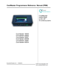
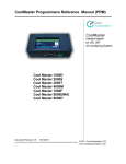
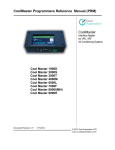
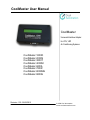
CoolMaster User Manual
CoolMaster
Universal Interface Adapter
for VRV, VRF
Air Conditioning Systems
CoolMaster 1000D
CoolMaster 2000S
CoolMaster 3000T
CoolMaster 4000M
CoolMaster 6000L
CoolMaster 7000F
CoolMaster 8000MH
CoolMaster 9000H
Revision 1.00 26/06/2012
© 2008 Cool Automation
www.coolautomation.com
CoolMaster User Manual
Contents
2
Table of Contents
Foreword
0
General Description
3
Overview
...................................................................................................................................3
Compatibility
...................................................................................................................................3
Main Features
...................................................................................................................................4
Functional Description
5
Specifications
7
Port Definition
...................................................................................................................................7
...................................................................................................................................8
Technical specifications
Installation Instructions
Accessories
9
...................................................................................................................................9
...................................................................................................................................9
Placement and Mounting
Power Supply
...................................................................................................................................10
...................................................................................................................................11
Connecting to non VRV/VRF
Units
...................................................................................................................................12
Connecting and Wiring
Precautions
User Interface
...................................................................................................................................14
15
...................................................................................................................................15
LCD Screen Explanation
Led Functions
...................................................................................................................................16
PC Connectivity
...................................................................................................................................16
Commands List
...................................................................................................................................19
Troubleshooting
www.coolautomation.com
20
© 2008 Cool Automation
CoolMaster User Manual
1
General Description
1.1
Overview
General Description
3
CoolMaster is a versatile seamless Control adapter connecting VRV / VRF Air Conditioning Systems
with any RS232 or USB featured devices like Home PCs, Embedded PCs or Home Automation
Controllers.
Connecting such Controllers through common RS232 or USB interfaces with the CoolMaster will
provide end-users with full control of all indoor units enabling them with access to HVAC's various
functionalities including diagnostic.
Home Automation Integrators and HVAC installers when utilizing CoolMaster will not have to worry
anymore about the complexity involved in understanding and working with HVAC's internal
Communication lines and gateways including their unique physical layers.
Now, with the CoolMaster integrators will be provided only with a simple, well documented open ASCII
protocol over RS232 or USB to seamlessly integrate with any Home Automation applications. . The
product is provided with LCD that continuously indicates the status of indoor units and malfunction
alerts. Basic connectivity of the product to the system can be viewed in the following schematic.
1.2
Compatibility
The CoolMaster range of products is compatible with several leading VRV/VRF air conditioning
systems. Each manufacturer requires different model of the CoolMaster, as described in the following
table.
VRV/VRF Manufacturer
Daikin
Sanyo
Toshiba
Mitsubishi Electric
LG
www.coolautomation.com
Product Name
CoolMaster 1000D
CoolMaster 2000S
CoolMaster 3000T
CoolMaster 4000M
CoolMaster 6000L
© 2008 Cool Automation
CoolMaster User Manual
Fujitsu
Mitsubishi Heavy
Hitachi
General Description
4
CoolMaster 7000F
CoolMaster 8000MH
CoolMaster 9000H
In VRV/VRF air conditioning system, regardless of the specific AC manufacturer, CoolMaster should
be connected to the main air conditioning communication line. The specific details about connection to
the AC system are provided in Connection and Wiring paragraph.
Using the CoolMaster with non VRV/VRF systems will require additional interface adaptors for each
indoor unit.
VRV/VRF
Manufacturer
Daikin
Mitsubishi Electric
Product Type
Interface Adaptor
Split, Sky Air, Multi
Mr Slim, Multi Split
Toshiba
RAV series
KRP928, DTA112, DTA102
MAC-399IF-E, PAC-SF81MA
TCB-PCNT30TLE2
LG
Inverter splits
PI485
Mitsubishi Heavy
split units
SC-ADNA-E
Detailed description of connectivity can be found in Connection to non VRV/VRF Units paragraph.
CoolMaster can be connected to different home automation controllers that have a controllable RS232
port (Vantage, Lite Touch, Unitronics, AMX, Crestron, Pronto, Control4, Domintel, etc), BMS, PC.
1.3
Main Features
· Simple RS232 Interface for Easy Integration
· Monitoring of the Air Conditioning System
· Operation Status
· Operation mode (Cool/Heat/Fan/Dry/Auto)
· Set Point Temperature
· Fan Speed
· Room Temperature
· Swing status (On/Off)
· Filter Sign
· Malfunction code
· Controlling of the Air Conditioning System
· Operation status (On/Off)
· Operation mode (Cool/Heat/Fan/Dry)
· Set Point Temperature
· Fan Speed
· Reset Filter Sign
· Swing (On/Off)
· Plug&Play Device
· Field Upgradeable Firmware
· Customizable for Specific Applications
www.coolautomation.com
© 2008 Cool Automation
CoolMaster User Manual
2
Functional Description
5
Functional Description
Simple RS232 Interface for Easy Integration
CoolMaster is equipped with an RS232 serial port. The port can be used in two different ways:
1. Configuration and monitoring of the air conditioning system from PC using simple Windows
based terminal program. (See PC connection)
2. Connected to Home Automation controller or BMS.
See Commands List for brief description of supported commands. The complete documentation can
be found in the Programmers Reference Manual.
Air Conditioning System Monitoring
CoolMaster enables Home Automation controllers or BMS to receive the air conditioning system
status. The status is provided by CoolMaster as a response to "stat" command (The syntax and
operands of the command can be found in the Programmers Reference Manual). CoolMaster provides
the following information for each indoor unit of the AC system:
· Operation mode - This parameter indicates whether the required indoor unit is set for Cooling,
Heating, Fan, Dry or Auto operation.
· The feedback returns the operation mode regardless of operation status (whether the unit is "ON" or "Off').
· Within the same air conditioning system different indoor units can be in different operation modes.
· Set Point Temperature - This is the desired temperature defined by the user on a given indoor unit.
· Fan Speed - Currently set fan speed of the monitored indoor unit. There are 4 available Fan Speeds:
High, Medium, Low and Automatic.
· Sanyo and Toshiba support all 4 Fan Speeds.
· Most of the Daikin indoor units support only 2 Fan Speeds: High and Low.
· Some of the new Daikin units (FXDQ-P and FXMQ) support 3 Fan Speeds: High (HH), Medium (H) and Low
(L).
· Room Temperature - This is the temperature, measured in the return air inside the monitored indoor
unit.
· This temperature measurement shows only the temperature inside the indoor unit and it doesn't always
indicate correctly the temperature in the room.
· Swing status - This parameter indicates whether the swing operation is "on" or "off" in the monitored
indoor unit.
· This parameter is only available for wall mounted and cassette type indoor units.
· Filter Sign - Each indoor unit is designed to show a reminder regarding cleaning of the filters. After
certain number of operation hours the "filter" sign will be shown on the local remote controller. The
time period, after which the sign appears may differ between different types of indoor units.
· Malfunction code - When abnormal operation of the air conditioning system occurs, there will be an
indication, regarding the malfunction. The malfunction can be local. In this case the specific indoor
unit will halt and malfunction code will appear on the local thermostat. When the malfunction is
general, the entire air conditioning system will stop and the malfunction code will show in all local
thermostats.
· When running "stat" command for a certain indoor unit there could be more than one malfunction code.
www.coolautomation.com
© 2008 Cool Automation
CoolMaster User Manual
Functional Description
6
Controlling the Air Conditioning System
· Operation mode - CoolMaster enables Home Automation controllers or BMS to set the operation
mode of each indoor unit independently. Cool, Heat, Fan, Dry and Auto operations are possible.
· For heat pump air conditioning system Coo" and Heat operation status cannot be set simultaneously for 2
different indoor units. For example, once at least one of the indoors has been set for Cool, all other indoor units
of the system cannot be set to Heat.
· In Daikin air conditioning systems one of the indoor units can be set as a master for Cool or Heat operation. In
this case, Cool or Heat operation of the entire air conditioning system may be carried only by sending the Cool
or Heat command to this specific indoor unit. Sending the Cool or Heat command to other indoor units will have
no effect.
· Operation status - CoolMaster enables Home Automation controllers or BMS to turn indoor units to:
ON and OFF.
· Set Point Temperature - The Set Point Temperature of each indoor unit can be changed separately
in two ways:
1. Defining the desired temperature.
2. Raising or lowering the existing set temperature by the defined delta.
· Fan Spped - CooMaster enables Home Automation controllers or BMS to change the fan speed of
the specified indoor unit.There are 4 available fan speeds: Low, Medium, High and Auto.
· Sanyo and Toshiba support all 4 Fan Speeds.
· Most of the Daikin indoor units support only 2 Fan Speeds: High and Low.
· Some of the new Daikin units (FXDQ-P and FXMQ) support 3 Fan Speeds: High (HH), Medium (H) and Low
(L).
· Reset Filter Sign - Each indoor unit is designed to show a reminder regarding cleaning of the filters.
After certain number of operation hours the "filter" sign will show on the local remote controller. The
time period, after which the sign appears may differ between different types of indoor units.
CoolMaster enables Home Automation Controllers or BMS to send a command to the system that
will reset the filter sign.
· Swing (On/Off) - CoolMaster enables Home Automation Controllers or BMS to change the status of
the "Swing" function on each indoor unit from "On" to "Off" and vise versa. Swing function is
available on wall mounted and cassette type
Plug&Play Device
When CoolMaster is connected to the air conditioning system, it does not require any additional
configuration. After connecting the wiring, supplying the power and defining addresses of the indoor
units (as explained in the installation chapter) the system is ready to work.
Field Upgradeable Firmware
When new features are added or some changes have been applied to the CoolMaster's functionality,
the firmware of the already installed CoolMaster can be easily upgraded by the user himself. The latest
firmware can always be downloaded from http://www.coolaut.com/secdown/ using the following user
name and password:
User
: cooluser
Password : coolpasswd
The upgrade process is described in details in the Programmers Reference Manual.
Customizable for Specific Applications
CoolMaster has a number of optional functions, that can be ordered by request in order to fit specific
customer's needs. Example of optional features:
1. Digital/Analog I/O.
2. Connection to the additional devices, such as CoolEx, CoolBridge etc'.
www.coolautomation.com
© 2008 Cool Automation
CoolMaster User Manual
3
Specifications
3.1
Port Definition
Specifications
7
RS232 Interface connector used in Cool Master is D-Type 9-pin DB9 female connector.
Cool Master DB9 Connector front view
DB9 Pin
2
3
5
Signal Lvel
±12V
±12V
GND
Description
TxD (Data from Cool Master)
RxD (Data to Cool Master)
Ground
Connecting Cool Master to Home Automation Equipment
According to RS232 specification cable length should not exceed 25m. RS232 Cable supplied with
Cool Master is 1.5m length suitable for direct connection to PC RS232 serial port.
Please note that for certain controllers it will be mandatory to use cable with cross linked the Transmit(2) and the
Receive(3) pins.
www.coolautomation.com
© 2008 Cool Automation
CoolMaster User Manual
3.2
Specifications
8
Technical specifications
Item
Power Supply
Installation Method
Surrounding
C
Temperature
Humidity
%
Dimensions
HxWxD
mm
Weight
gr
LCD
Characters
Maximal number of indoor units
Maximal number of outdoor units
Maximal allowable wiring length (to BMS over
m
RS232)
RS232
Communication functions
Aircon Communication
Operating Conditions
www.coolautomation.com
Specification
9 v DC
Wall Mounted or DIN Rail Mounted
0 – 45 °C
Less then 85 % RH
30 x 115 x 60
300
16 x 1
Depends on the manufacturer
Depends on the manufacturer
25
9P RS232 Port (Femail Connection)
2 wired cable
© 2008 Cool Automation
CoolMaster User Manual
4
Installation Instructions
4.1
Accessories
Installation Instructions
9
Standard Accessories
The following accessories are shipped in the kit. The power adaptor can be selected according to
domestic AC standards (see Power Supply).
Name
Quantity
RS232 Cable
1
Power Adaptor
1
Shape
Optional Accessories
The following accessories can be supplied at request depending on the desired installation location of
the CoolMaster.
Name
Quantity
DIN Rail Fixing
1
Shape
4.2
Wall Mounting Plate
1
Currently N / A
Placement and Mounting
The CoolMaster should be placed in a dry ventilated place. It is advised to be installed in the electricity
cabinet near the BMS/Home Automation controller since the length of the RS232 connecting cable is
limited (see Technical specifications). In this case it is advised to use the optional DIN Rail Fixing, as
shown in the following diagrams.
Another option is mounting the CoolMaster directly on wall with Wall Mounting Plate (Accessories).
www.coolautomation.com
© 2008 Cool Automation
CoolMaster User Manual
4.3
Installation Instructions
10
Power Supply
The CoolMaster device requires standard power supply of 9V DC voltage. The power transformer is
included in the kit and varyies according to the country of the user. Please make sure there is a
standard power plug point prepared near the CoolMaster for connection of the power transformer. The
supplied types of the power transformer are described in the following table:
AC Parameters
Regions & Countries
110 - 120 v
60 Hz
USA, Canada, Japan,
Mexico, Brazil, South
America
220 - 240 v
50 Hz
United Kingdom
220 - 240 v
50 Hz
Australia, New Zealand,
Asia
220 - 240 v
50 Hz
Europe, South Africa,
Israel, Russia,
Hong Kong, India
Picture
It is not recommended to use a substitutional power adaptor.
www.coolautomation.com
© 2008 Cool Automation
CoolMaster User Manual
4.4
Installation Instructions
11
Connecting to non VRV/VRF Units
CoolMaster can be used also with split units. In this case each indoor has to be provided with a
communication interface (for example, D3 net interface for Daikin Units, M-Net interface for Mitsubishi
Electric units, etc'). All those interfaces are plugged into the PCB of the indoor unit (the cable is
provided with the interface), and their output has to be inter chained by 2 wired communication line,
similarly to the wiring connection of the indoor units in a regular VRV/VRF system. CoolMaster has to
be connected to this line, as shown in the following diagram.
When using the CoolMaster 1000D with KRP928 or DTA102/112 adaptors in Multi/Split/Sky air range
of Daikin Air Conditioning systems a change should be made also inside the CoolMaster itself. This
change should be made only if there is no VRV/Centralized Controller connected to this F1 F2
communication line1. Change will be as follows:
Step1 - Open the top cover of the unit
Step 2 - Change the position of the dip switch (all 4 pins), as shown in the following figure
Original Position (Factory supplied)
New Position
Please note, that when using CoolMatser with Daikin KRP and DTA D3 net interfaces, the fan speed control and
room temperature monitoring is not possible.
www.coolautomation.com
© 2008 Cool Automation
CoolMaster User Manual
4.5
Installation Instructions
12
Connecting and Wiring
Connecting the CoolMaster to the system is done by 3 steps:
1. Power supply connection.
2. Connecting to the Air Conditioning Communication line.
3. Connecting to the BMS/Home Automation controller.
Power Supply Connection
The power plug is supplied with the CoolMaster and connected as shown in the following figure.
Connecting to the Air Conditioning Communication line
The CoolMaster is simply wired to the Main air conditioning Communication Line anywhere within the
system. It can be wired to the terminals on one of the indoor units, directly to the terminals on the
outdoor unit or to the terminals on one of the centralized controllers. A connectivity schematic is shown
in the diagram below.
www.coolautomation.com
© 2008 Cool Automation
CoolMaster User Manual
Installation Instructions
13
Make sure to connect the communication wires to exact terminal names according to the table below.
Daikin Toshib Sanyo Mitsubis Fujitsu
a
hi
Electric
D3 Net TCC
S3 Net M-Net
VRF
Main
Link
(TB3,
transmissi
Communicatio
TB7)
on line
n Line
F1 F2
Terminal
names
none
Polarity
64
Number of
Indoors
10
Number of
Outdoors
Shielded wiring not
required
Mitsubis
hi Heavy
Hitachi
U1 U2
U1 U2
M1 M2
X1 X2
Super
Link
New
Super
Link
AB
none
64
none
64
none
50
none
64
none
128
none
64
Inter A,
Inter B
(outdoor
only)
none
128
10
10
10
10
10
10
10
required
required required
required required required
H Link, H
Link 2
LG
12
required
The connection to the CoolMaster is performed by a specified plug, as shown in the picture below.
The communication wiring usually consists of two wires with 0.75-1.25 mm2 cross section diameters.
The wiring diameters must be the same as the wires used within the air conditioning system, according
to the AC manufacturer requirements. The total wiring length within the system should not exceed AC
manufacturer limitations. The following table describes the wiring specifications for different
manufacturers
Connecting to the BMS/Home Automation Controller
The onboard RS232 connector of the CoolMaster is used for configuration, and connection to the
BMS/Home Automation controller. The 1.5 m long RS232 Male/female cable is supplied with the
CoolMaster.
· In order to operate Daikin Air Conditioning systems all the indoor units must be provided
with the centralized addresses
· Main Communication Line is defined as the communication line between the indoor and
the outdoor units.
· Please make sure not to connect the CoolMaster to the communication line between the
indoor unit and its local remote controller.
· CoolMaster 6000L (LG) must be connected to the terminals of the outdoor unit (Inter A,
Inter B)
www.coolautomation.com
© 2008 Cool Automation
CoolMaster User Manual
4.6
Installation Instructions
14
Precautions
Attention
1. During the system automatic operations the CoolMaster must be disconnected from the system.
Examples of the automatic operations are:
· Test
· Reset
· Automatic charge
2. Do not change the original positions of the quadruple dip switch SW1 inside CoolMaster when using
it with VRV/VRF systems.
www.coolautomation.com
© 2008 Cool Automation
CoolMaster User Manual
5
User Interface
5.1
LCD Screen Explanation
User Interface
15
Two types of screens can appear on the LCD of the CoolMaster. One screen shows the indoor units
status, as shown in the figure and the explanation table below.
The following table describes what is shown on the LCD Display of the CoolMaster.
Segment
Description
Number
1
Address of the indoor unit
2
Operation Status
3
Set Point Temperature
Range
Example
100 - 815
101
"+" - off,
"-" - on
"-"
16 - 32
"18"
Low
Medium
4
Fan Speed
High
high
Auto
5
Operation Mode
6
Filter Sign
7
Error Status
Cool Heat Fan Dry
OK - Normal Opearation
U4 - example of
malfunction
"Cool"
Ok
Another screen shows the number of identified indoor units and number of groups
U – Number of recognized indoor units (in the example above – 10)
G – Number of groups (in the example above – 8)
A3 U4 – current malfunction codes in the system
www.coolautomation.com
© 2008 Cool Automation
CoolMaster User Manual
5.2
User Interface
16
Led Functions
The unit is equipped with 2 leds, as can be seen in the figure below.
Leds indicate whether there is a communication with the Air Conditioning system. When there is no
communication, the upper led is off. When the CoolMatser senses the communication from the Air
Conditioning system, the upper led starts blinking. The lower led is currently not functioning.
5.3
PC Connectivity
When the CoolMaster is connected to the air conditioning system it is suggested to check its
performance by connecting it to a PC or Laptop.
In order to do so the device has to be connected to the serial PC Port (RS232) or to USB port by using
a transformer cable RS232 to USB and appropriate driver.
After the connection, the “Hyper Terminal” program should be engaged, using the following sequence:
Start -> Programs -> Accessories -> Communications -> Hyper Terminal
www.coolautomation.com
© 2008 Cool Automation
CoolMaster User Manual
User Interface
17
In the opened window “Connection Description” an arbitrary name should be chosen.
Then, in the next window named “Connect to” a correct port has to be chosen at the bottom box,
called: “Connect Using:” (for example: modem, com1, com4 etc’).
Next, the port setting has to be defined as following:
After finishing the above definitions, if everything is correct, the version of the CoolMaster software is
www.coolautomation.com
© 2008 Cool Automation
CoolMaster User Manual
User Interface
18
supposed to appear at the top of the window.
At this point all the commands from the command list can be typed and transferred to the air
conditioning system.
www.coolautomation.com
© 2008 Cool Automation
CoolMaster User Manual
5.4
User Interface
19
Commands List
on
- on <UID
Turn the unit on
off
- off <UID>
Turn the unit off
temp
- temp <UID> <temp>
Defines the unit’s Set Point
cool
- cool <UID>
Turns the system to the cooling mode
heat
- heat <UID>
Turns the system to the heating mode
fan
- fan <UID>
Turns the system to the “Fan” mode
dry
- dry <UID>
Turns the system to the “Dry” mode
auto
- auto <UID>
Turns the system to the "Auto" mode
fspeed - fspeed <UID> <l|m|h|a>
Sets the unit’s fan speed
swing
- swing <UID>
Turns on/off swing operation
stat
-
Prints the status of the all indoor units
stat
- stat <UID>
Prints status of the specified indoor unit
stat2
-
Prints the status of all indoor units (including filter sign)
stat3
-
Prints the status of all indoor units when each parameter
has a constant place in the string
set
- set [<echo|myid> <val>
allon
-
Turns all the indoors on
alloff
-
Turns all the indoors off
boot
-
Runs bootloader
simul
- simul <N>
Simulates the specified number of indoors
filt
-
Resets Filter Sign
For detailed updated info please refer to the "Programmers reference manual" document.
www.coolautomation.com
© 2008 Cool Automation
CoolMaster User Manual
6
Troubleshooting
20
Troubleshooting
Symptom
The LCD of the
CoolMaster is off
1
(there is no visible
display on it).
After connecting the
CoolMaster it does
2 not show on its LCD
the correct number of
indoor units.
Cause
a. Incorrect power supply
a. Check the power adaptor and supplied
voltage. Must be stable 9v DC.
a. It takes several minutes
to recognize the system.
b. The communication line
to the air conditioner is
connected improperly.
a. Wait for about 5 minutes
b. Check the connection of the air conditioner
communication line. Look if the upper led is
blinking.
c. If the led is off, check the wiring connection
of the communication line.
a. Improper serial port
definitions.
b. The centralized
The communication addresses of the indoor
does not work (the
units are not defined.
3 system does not react c. The wires: transmit and
to any of your sent
receive of the RS232 cable
commands).
are not twisted.
d. Carriage return has not
been added to your
command.
The typed commands
cannot be seen on the
4
a. The echo is set to "off".
"hyper terminal"
screen
www.coolautomation.com
What to do
a. Check that all port definitions (baud rate,
flow control, parity etc’) are properly defined.
b. Define the centralized addresses of all
indoor units.
c. Check and fix the RS232 cable connection
(twisting the Tx and Rx wires).
d. Add “0d” at the end of the command that is
sent to the CoolMaster.
a. Run "echo" command and set "echo" to
"On".
© 2008 Cool Automation