1
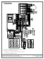
Installation Instructions
for the
DS7420i Dual Phone Line/Bell Supervision
Module
•
Maximum Loop Resistance: Class “A” loop tolerates a
maximum loop resistance of 150 ohms total.
•
Operating Temperature: +32° to +120°F (0° to +49°C)
•
Ringer Equivalence Number (REN) = 0.1B
Table Of Contents
1.0 Description......................................................................1
2.0 Specifications.................................................................1
3.0 Installation
3.0 Installation.......................................................................1
The DS7420i should be mounted within a DS7400Xi enclosure.
For programming information, refer to the DS7400Xi Reference
Guide (P/N: 40816 for Ver. 4+, P/N: 28995 for Ver. 3+) .
4.0 Operation.........................................................................2
5.0 FCC Compliance Notice.................................................3
NOTE: The DS7400Xi control must be installed in accordance
with NFPA 72 guidelines.
6.0 FCC Phone Connection Notice to Users......................3
7.0 Canadian Department of Communications..................3
8.0 Wiring Diagram...............................................................4
1.0 Description
3.1 Hardware Installation
•
Disconnect power from the control panel. Unplug the
transformer and remove the red battery lead.
The DS7420i is an accessory board designed for use with the
DS7400Xi control/communicator. It allows the control to be used
in NFPA 72 installations. The DS7420i provides two supervised
12 VDC signaling outputs, one Class A (Style D) input zone, and
dual phone line transmission and supervision.
NOTE: For Commercial Fire applications, the TR1850 transformer (Basler Electric BE116250CAA) must be
enclosed in the AE-TR16 Transformer Enclosure. The
wiring from the AE-TR16 to the control and the wiring to
the outlet box in conduit must also be enclosed in the
AE-TR16.
•
System is Power Limited except for battery terminals. All
wiring entering this enclosure must be power limited.
•
•
FCC registration number: ESVUSA-20294-KX-N
3.2 Internal Wiring
•
DOC number: 1249 5895 A
•
2.0 Specifications
•
Auxiliary Power Requirements: Supervisory: 12 VDC,
nominal, 20 mA. Alarm: 140 mA.
•
Indicating Appliance Circuit (Bell Output): 12 VDC, special
application supervised output supplies up to 1.75 A for
vibrating bells.
•
Auxiliary Output Circuit: 12 VDC, special application
supervised output latches on alarm and resets upon system
reset. It is intended for strobes/indicating appliances and
supplies up to 1.0 A.
•
Initiating Device Circuit (terminals 13-16): The Class “A”
loop is intended for connection of Normally Open (closed on
alarm) dry contact initiating devices such as waterflow
switches.
The Class “A” loop will not support loop powered devices
such as two-wire smoke detectors.
Mount the DS7420i Module in the enclosure as shown on
page 4. Use the supplied mounting clips and screws.
Connect internal wiring as shown on page 4.
- Connect the options bus of the DS7420i (terminals 1-4) to
the options bus of the control panel.
- Connect the battery input (terminals 5 and 6) to the control
panel battery using the dual battery clips provided.
- Connect the control line phone input (terminals 21-24) to
the phone line output (13-16) of the DS7400Xi.
- If using the Class “A” zone, connect the zone input
terminals (11 and 12) to the zone 1 input (19 and 20) of the
control panel.
Note:
The DS7420i is fixed as address 15 on the control
options bus. If you are using a DS7400Xi Rev. 3
control/communicator, keypad 15 will not be available
for system use. See your DS7400Xi Reference Guide.
4.0 Operation
If the cause for the Supervisory condition has not been eliminated, the sounders will silence, but the “Supervisory” display
will not be cleared.
4.1 Normal Condition
Under normal conditions, the keypad Power and Status Lights will
be on steady.
•
4.2 Fire Alarm
During a fire alarm, the alarm sounding devices and the keypad
sounders will be activated. The keypad display will read “Fire
Alarm.”
•
To silence the fire alarm sounders:
Enter a valid PIN followed by the [Off] key. "Fire Alarm" and
“Sounder Silenced” will then be displayed.
•
To reset the system:
Eliminate the cause of the Supervisory condition. Then enter a
valid PIN followed by the [Off] key.
4.5 Control Trouble
During a Control Trouble, the Power Light will be flashing and the
keypad sounders will pulse every ten seconds. The keypad display
will read “Control Trouble/Press #87.”
A Control Trouble can be caused by several conditions.
•
Determine the cause of the alarm. Then enter a valid PIN
followed by [System Reset]. This command clears the "Fire
Alarm" and “Sounder Silenced” displays.
•
To silence the sounders:
-
AC Failure: AC power has been lost or has gone below the
“Brown Out” level. The Power Light will continue to flash until
AC power has been restored. If AC power restores while the
Trouble condition has been silenced, the sounders will begin
to pulse again.
-
Low Battery: The battery voltage has dropped below 12 VDC
or the battery is missing. The Low Battery condition may be
cleared, but will return if the battery fails the next battery test.
After clearing a Low Battery condition, the battery should
immediately be tested as described in the “Testing Procedure”
section below. If the battery restores while the Trouble condition
has been silenced, the sounders will begin to pulse again.
-
Bell Trouble: The bell circuit wiring is open or shorted. The
keypad sounders will pulse once every 10 seconds (if in
Commercial Fire Mode). The keypad display will read “2Ph/Bell
Fault.”
Enter a valid PIN followed by the [Off] key.
If the cause for the Trouble condition has been eliminated, the
sounders will silence and the “Fire Trouble” display will be
cleared.
If the cause for the Trouble condition has not been eliminated,
the sounders will silence, but the "Fire Trouble" display will not
be cleared. The keypad will also display the zone that is in the
Trouble condition.
•
To clear the display:
To silence the sounders, enter a valid PIN followed by the [Off]
key. If the cause for the Trouble condition has been eliminated,
the sounders will silence and the “2Ph/Bell Fault” display will
be cleared.
Eliminate the cause of the Trouble condition. Then enter a valid
PIN followed by the [Off] key.
4.4 Supervisory Signal
During a Supervisory Signal (e.g. wiring to supervisory zone has
been shorted), the keypad sounders will pulse once every 10
seconds. The keypad display will read “Supervisory” with a zone
number.
•
If the cause for the Trouble condition has not been eliminated,
the sounders will silence, but the “2Ph/Bell Fault” display will
not be cleared.
•
To clear a Control Trouble:
Eliminate the cause of the Trouble condition. Then enter a valid
PIN followed by [System Reset].
To silence the sounders:
Enter a valid PIN followed by the [Off] key.
If the cause for the Supervisory condition has been eliminated,
the sounders will silence and the “Supervisory” display will be
cleared.
Page 2
To determine the cause of the Control Trouble:
Enter a valid PIN followed by [#] [8] [7]. One of the following will
be displayed:
During a fire trouble (e.g. open on a Class A loop, open on any fire
loop), the keypad sounders will pulse once every 10 seconds. The
keypad display will read “Fire Trouble” with a zone number. A fire
trouble with no zone number indicates a ground fault.
•
To silence a Control Trouble:
Enter a valid PIN followed by the [Off] key.
NOTE: The control must be reset after a fire alarm or future
alarms will not be detected.
4.3 Fire Trouble
To clear the display:
4.6 Testing Procedure:
The sounders should be tested (at least weekly) using the keypad
activated Sounder Test.
© 2004 Bosch Security Systems
DS7420i Installation Instructions
The Sounder Test is activated by entering a PIN followed by [#] [8]
[5]. This test activates the sounders using power from the battery,
thereby, testing the battery. If the battery is defective, the system will
go into a Control Trouble condition. The system sirens and keypad
sounders will activate for two seconds.
If you experience trouble with this equipment, please contact the
manufacturer for information on obtaining service or repairs.
The telephone company may ask that you disconnect this equipment from the network until the problem has been corrected or until
you are sure that the equipment is not malfunctioning. The repairs to
this equipment must be made by manufacturer and not by the user.
5.0 FCC Compliance Notice
This equipment has been tested and found to comply with the limits
for a Class B digital device, pursuant to Part 15 of the FCC Rules.
These limits are designed to provide reasonable protection against
harmful interference in a residential installation. This equipment
generates, uses and can radiate radio frequency energy and if not
installed and used in accordance with the instructions, may cause
harmful interference to radio communications. However, there is no
guarantee that interference will not occur in a particular installation.
If this equipment does cause harmful interference to radio or
television reception, which can be determined by turning the
equipment off and on, the user is encouraged to try to correct the
interference by one or more of the following measures:
•
Reorient or relocate the receiving antenna.
•
Increase the separation between the equipment and the
receiver.
•
Connect the equipment into an outlet on a circuit different from
that to which the receiver is connected.
•
Consult the dealer or an experienced radio/TV technician for
help.
6.0 FCC Phone Connection Notice To Users
This control complies with Part 68 of the FCC rules.
On the top of the PCB is a label that contains, among other information, the FCC Registration Number and the Ringer Equivalence
Number (REN) for this equipment. You must, upon request, provide
this information to your local telephone company.
The REN is useful to determine the quantity of devices that you may
connect to your telephone line and still have all of those devices
ring when your telephone number is called. In most, but not all
areas, the sum of the REN's of all devices connected to one line
should not exceed five (5.0). To be certain of the number of devices
that you may connect to your line, you may want to contact your
local telephone company to determine the maximum REN for your
local calling area.
This equipment may not be used on coin service provided by the
telephone company. This control should not be connected to party
lines.
Should this equipment cause harm to the telephone network, the
telephone company may discontinue your service temporarily. If
possible, they will notify you in advance. But if advanced notice isn't
practical, you will be notified as soon as possible. You will be
informed of your right to file a complaint with the FCC. The telephone company may make changes in its facilities, equipment,
operations, or procedures that could affect the proper functioning of
your equipment. If they do, you will be notified in advance to give
you an opportunity to maintain uninterrupted telephone service.
To guard against accidental disconnection, there is ample room to
mount the Telco jack to the inside of the Control cabinet.
The operation of this Control may also be affected if events such as
accidents or acts of God cause an interruption in telephone service.
7.0 Canadian Department of Communications
General Installation Requirements:
Notice: The Canadian Department of Communications label
identifies certified equipment. This certification means that the
equipment meets certain telecommunications network, protective,
operational, and safety requirements. The Department does not
guarantee the equipment will operate to the user’s satisfaction.
Before installing this equipment, users should ensure that it is
permissible to be connected to the facilities of the local telecommunications company. The equipment must also be installed using an
acceptable method of connection. In some cases, the company’s
inside wiring associated with a single line individual service may be
extended by means of a certified connector assembly (telephone
extension cord). The customer should be aware that compliance
with the above conditions may not prevent degradation of service in
some situations.
Repairs to certified equipment should be made by an authorized
Canadian maintenance facility designated by the supplier. Any
repairs or alterations made by the user to this equipment, or
equipment malfunctions, may give the telecommunications company cause to request the user to disconnect the equipment.
Users should ensure, for their own protection, that the electrical
ground connections of the power utility, telephone lines, and
internal metallic water pipe system, if present, are connected
together. This precaution may be particularly important in rural
areas.
Caution:
Users should not attempt to make such connections
themselves, but should contact the appropriate
electric inspection authority, or electrician, as appropriate.
Terminal Requirements:
The Load Number (LN) assigned to each terminal device denotes
the percentage of the total load to be connected to a telephone loop
which is used by the device, to prevent overloading. The termination
on a loop may consist of any combination of devices subject only to
the requirement that the total of the Load Numbers of all the devices
does not exceed 100. The Load Number of the DS7420i is 2.
RFI Requirements:
This Class A digital apparatus meets all requirements of the
Canadian Interference-Causing Equipment Regulations.
[Cet appareil numerique de la classe A respecte toutes les
exigences du Reglement sur le material broilleur du Canada.]
DS7420i Installation Instructions
© 2004 Bosch Security Systems
Page 3
8.0 DS7420i Wiring Diagram
•
All input and output connections are inherently low voltage, power
limited. Use U.L. Listed power limited cable only.
•
This equipment is to be installed in accordance with NFPA Standard 72.
•
The control panel compatibilty identifier is C.
© 2004 Bosch Security Systems
130 Perinton Parkway, Fairport, New York, USA 14450-9199
Customer Service: (800) 289-0096; Technical Support: (888) 886-6189
5/04
DS7420i Installation Instructions
P/N: 30340F Page 4