1
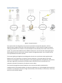
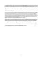
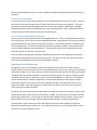
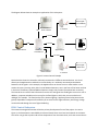
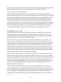
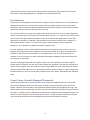
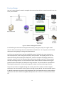
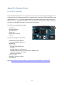
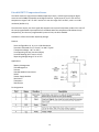
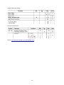
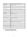
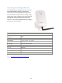
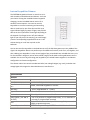
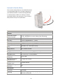
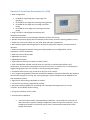
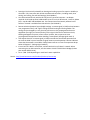
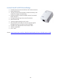
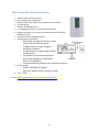
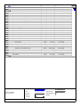
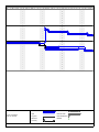
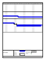
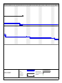
Vanderbilt University Automated Home Control Senior Design Project: Semester Report Project Members: Nick Atkinson Matt Majeika Ungku Afiq Ungku Farid Project Sponsor: Terry Slattery, Netcordia 07 ‐2‐ Table of Contents Introduction .................................................................................................................................................. 5 System Overview .......................................................................................................................................... 6 Intentions This Year .................................................................................................................................. 7 Operational Concept ..................................................................................................................................... 8 Control Server Subsystem ......................................................................................................................... 8 Control of Insteon Devices .................................................................................................................. 9 Control of Network‐Managed Thermostat ........................................................................................ 9 Lighting Control Subsystem ...................................................................................................................... 9 HVAC Control Subsystem ........................................................................................................................ 10 Water Heater Control Subsystem ........................................................................................................... 11 Accomplished Last Year .............................................................................................................................. 11 User Interface ............................................................................................................................................. 12 Project Focus: Network‐Managed Thermostat ........................................................................................... 12 Previous Design ....................................................................................................................................... 13 Commercial Thermostat Integration ...................................................................................................... 14 Project Plan ................................................................................................................................................. 16 Appendix A: Hardware Listing ..................................................................................................................... 17 PIC16F877A Controller ............................................................................................................................ 17 Fairchild FM75 Temperature Sensor ...................................................................................................... 18 Matrix Orbital LCD2041‐WB LCD Screen ................................................................................................ 20 Digi Wi‐EM Module ................................................................................................................................. 21 Insteon PowerLinc Controller V2 ............................................................................................................ 22 Insteon LampLinc .................................................................................................................................... 23 Insteon ApplianceLinc ............................................................................................................................. 25 Insteon SwitchLinc Dimmer .................................................................................................................... 27 Insteon SignaLinc RF Signal Extender ...................................................................................................... 30 Insteon KeypadLinc Dimmer ................................................................................................................... 31 Insteon In‐LineLinc Relay ........................................................................................................................ 34 Omnistat‐Z from Home Automation Inc. (HAI) ....................................................................................... 36 Leviton Vizia RF to RS232 Serial Bridge ................................................................................................... 38 TR16 from Residential Control Systems .................................................................................................. 39 ‐3‐ TZ16 from Residential Control Systems .................................................................................................. 40 RS‐485 to RS‐232 Converter .................................................................................................................... 41 HomePro RF RS‐232 Interface ................................................................................................................. 42 Aprilaire 8870 Communicating Thermostat ........................................................................................... 43 Aprilaire 8818 Distribution Panel ............................................................................................................ 44 Aprilaire 8811 .......................................................................................................................................... 44 Appendix B: Expanded Project Schedule .................................................................................................... 46 ‐4‐ Introduction With increasing energy concerns, different methods of conservation have appeared. One of the fastest growing areas of energy conservation is that of home automation. By increasing control of various devices in a house, the energy they consume can be controlled and reduced. The purpose of this senior project is to design and implement a home automation system. This is a continued project from the previous 2006‐2007 academic year. Companies such as Home Automation, Inc. (HAI) and Destiny Networks offer various home controllers. The system designed in this project is more similar to the solutions offered by HAI, because Destiny Networks focuses more on home entertainment systems. The primary difference between our system and the available HAI systems is the use of wireless networking, which greatly reduces installation complexity and cost. The goal of the system is to provide control of lighting and various appliances via a local area network. A web interface will allow users to both monitor and control the system. In order to demonstrate our project functionality, we will install our automated home control system in a home. One part of this installation will be lighting control devices. Another part of this installation will be a network‐managed thermostat that exhibits manual and remote control. In order to control both of these subsystems, we will also install a home control server. The software and conceptual design for these subsystems were developed last year, but we plan to implement them and see them function. ‐5‐ System Overview Figure 1: System Overview The system which was designed by the previous team aimed at two specific objectives. The first objective was to integrate the entire smart home subsystems in a way such that it could be accessed and programmed from one interface. The second objective was to develop the control scheme for the system. The system was divided into three different subsystems. The first was the Insteon lighting and home appliance control. Next was the wireless network‐managed thermostat. Last, the home control server provided control and an interface. The Insteon lighting and appliances was designed so that the user could control each appliance and lighting in his or her house from a PC with an internet connection. The system gave the user total control over the brightness and switching options of the lighting equipments (incandescent, fluorescent) and lamps. Appliances connected to the Insteon devices could also be set to on/off mode. This subsystem consisted of a PowerLinc V2 and other Insteon nodes. The network‐managed thermostat allowed the user to control the HVAC system based on predetermined or automated schedules. The idea was to develop it as a custom digital thermostat which is wireless. This subsystem consists of a Digi Connect Wi‐EM, a PIC controller, an LCD screen, a three way switch and a four button keypad. ‐6‐ The home control server gave total control using a web based application to control the two subsystems from any internet connection. The user inputs the command from the web interface. The web interface then compiles the command and passed it to the abstract interface. The abstract interface acts as a link between the web interface and the hardware controller. Intentions This Year Since the wireless network‐managed thermostat subsystem was never actually tested, we have decided to make some improvements and test it. One of the reasons is that there are actually many different types of thermostats. In order to demonstrate the system works, it has to be configured to a particular thermostat. We plan to fully utilize the equipments available and implement this subsystem. In addition to testing and implementing the existing design, we plan to integrate a commercial thermostat to our design. This will serve to compare the two approaches in parallel. We also plan to link the Insteon subsystem and the network‐managed thermostat subsystem using the home control server. Our aim is to fully demonstrate the whole system working. For this, we need to come up with a testing system to implement the overall system. A lot of things have to be taken into consideration. First is the size and location of a particular area to test it. The next thing is to set up the equipment so that it is compatible with the lighting, appliances and HVAC being used in the test area. The designated test area for our project is Professor Dozier’s home. ‐7‐ Operational Concept Our fully functional automation system will consist of four major subsystems that play a key part in home energy savings. Refer to the figure, below, for a visual representation of this system. Figure 1: System Overview At the heart of the system is the control server, which will contain all of the software for controlling the system’s functionality. The lighting control subsystem will communicate to the control server via the PowerLinc V2 module. Lights and household appliances can be remotely turned on and off through communication with the PowerLinc V2. The HVAC control subsystem will be monitored with network‐ managed thermostats in the house. The thermostat will communicate wirelessly, using IEEE 802.11b protocol, to the control server. The commercial thermostat may use a wired system to communicate with the control server. The water heater monitoring subsystem will serve to observe, adjust, and schedule water heater operation based on user input through the control server. These four components will form the system control for our home automation project. Control Server Subsystem The Home Control Server in Figure 1 is the communication core of the project. It uses a Linux platform to control all of the other system components. For prototyping in the lab, we will be using a laptop dual‐ booted with the Linux Ubuntu operation system. However, when implementing the final form of the system in a home, we will dedicate a Linux machine as the control server. The software for the server ‐8‐ control logic was written by last year's team. Changes and additions will be made to the control logic as necessary. Control of Insteon Devices Ion is an open‐source library with a USB driver for the Insteon PowerLinc Controller V2 (PLC). Using Ion, the server can send commands to the PLC, which then transmits via the Insteon network. The server uses another program called IonBridge to poll the PLC with event handlers. Additionally, IonBridge allows applications to control Insteon devices by using command servers. All the needed software for Insteon network control has been written by the previous team. Control of NetworkManaged Thermostat The control server also controls the network‐managed thermostat. There is existing code from last year that interfaces the server with the custom‐designed thermostat. Commands are sent using TCP sockets requesting data from the thermostat or giving it instructions. The interface software is already written for the existing design. For the purchased communicating thermostat, however, we will need to write similar software to perform the same functions. The server will contain the scheduling data and the same information as the LCD on the thermostat. The only software development needed for the Home Control Server is the integration of the off‐the‐ shelf communicating thermostat with the control system. This will be no easy task, but will become a requirement as we develop the two thermostat designs in parallel. Lighting Control Subsystem The lighting in our home automation system is controlled by Insteon devices, as noted in Figure 1. Insteon utilizes a dual‐mesh network to communicate with devices in the home, making it very effective and reliable. Signals are sent over the home's power lines and through radio transmission, giving signals multiple paths and increasing reliability. The devices can either plug into an outlet, providing a remote‐ controlled outlet for lamps / appliances, or they can be installed directly in a light's circuit, providing a remote‐controlled relay. Switches and dimmers can be used throughout the subsystem to replace existing wall switches. Each device has a factory‐loaded ID number so the Home Control Server can target it specifically. With the availability of outlet controls as well as in‐line relays, this system will prove to be quite versatile and useful. The server can communicate with the Insteon devices through the PowerLinc Controller V2 (PLC), which communicates directly with the Home Control Server via USB. The PLC provides the interface from the Insteon gear to the server. It is the origin of the dual‐mesh network used in the house. Other Insteon devices include relays, lamp plugs, appliance plugs, keypad controllers, and RF signal enhancers. The RF SignaLinc signal enhancers receive radio signals from the PLC and strengthen the signal to devices connected to the AC power lines. This is especially important sue to the high quantity of noise that exists on a home AC power system. ‐9‐ The diagram below shows an example an application of this subsystem: Flood Lights – Front Walkway RF Motion Detector – Front of House In-LineLinc 110 VAC USB Home Control Server 110 VAC PowerLinc Controller V2 ApplianceLinc Coffee Maker RF 110 VAC Flood Lights – Back Yard Motion Detector – Back of House In-LineLinc Figure 2: Insteon Control Example Notice that the PowerLinc Controller is directly connected to 5 different Insteon devices. It is wired directly to the ApplianceLinc and both In‐LineLinc Relays. It is wirelessly connected to the Motion Detectors via RF signals. In this example, the ApplianceLinc can be set to turn a coffee maker on at a certain time every morning. Also, there are two Motion Detectors, one in the front of the house and one in the back. The battery‐operated Motion Detectors simply relay motion information back to the PLC. The Control Server receives the information from the PLC and signals the flood lights to turn on or off. In addition, a separate schedule can be set up for the flood lights in which they turn on at dusk until midnight, for example. The functionality of the Insteon lighting / appliance control subsystem can be greatly expanded to incorporate functionality of an entire house. Higher efficiency and energy‐savings can be achieved through the use of light‐scheduling. HVAC Control Subsystem The network‐managed thermostat will be the primary development focus of the project. As seen in Figure 1, the thermostat is controlled by the Home Control Server via a local area network in the home. The server can get the set point and current temperature from the thermostat, and it can control the set ‐10‐ point, HVAC, and mode. The thermostat can run on stand‐alone manual mode, in which the user simply uses the keypad, or the server can control the thermostat with user‐defined scheduling. Water Heater Control Subsystem Last year’s team had allotted water heater control as a subsystem of this home automation project. Although we will not have the time or resources to complete this aspect of the project this year, it would certainly make a great addition in a future project. The water heater control would function in a similar fashion as the heating and cooling in the house. It would act to monitor and regulate the operation schedule of the water heater so that home residents wouldn’t be without hot water but without the heater constantly running. The user could set up a schedule that included turning on before the morning so that showers could be hot. It’s not necessary to keep it running all day while at work, so it could be set to pilot (standby) mode during the day. This subsystem would include sensors that monitor the intake and outflow temperatures so that an optimal schedule can be automated by the system. Accomplished Last Year As previously mentioned, this project is a continuation from last year. While last year's team made significant progress, the resulting project was incomplete due simply to time constraints. The main accomplishment from last year was the control of lighting and other home appliances using the home control server over the Insteon home automation technology. The previous team used Linux OS as the platform to develop the home control server software. The software consists of three different levels. The highest level is the web user interface which ties all the system controls. This is the where the user access and manages the equipments. The web interface is also accessible from any PC with an internet connection. The second level is “Ion Bridge” which is an abstract interface use to receive PLC (Insteon PowerLinc V2) events and send messages to the Insteon devices. The lowest level is “Ion” which is basically the driver library for the PLC. Ion is an open source code available on the web and was never actually finished by anyone. The team managed to complete the code and successfully compile it to work with the “Ion Bridge”. A USB cable was used to connect the PLC with the home control server. The individual Insteon nodes (which control the lighting and other home appliances) were connected to the PLC using two different signals; electrical phases of the home 110 VAC line and RF. There were different types of Insteon nodes used. The first is SwitchLinc which provides control to incandescent bulbs, low‐voltage halogen and fluorescent bulbs for up to 32 brightness levels. LampLinc has the same functionality as SwitchLinc but it is used for lamps instead. The ApplianceLinc provides control to home appliances and can only be programmable to on/off command. In order to demonstrate the functionality of the equipments during design day, the previous team constructed a model home circuitry board. There were two main circuits. The first circuit consists of SwitchLincs, ApplianceLincs and power outlets. The second circuit consists of LampLincs and also power outlets. The SwitchLincs is supposed to represent the lighting circuit. All the other lincs and power outlets represent the house electrical wiring. Two RF signal enhancers were used to increase the RF ‐11‐ signal send from the PLC to the Insteon nodes and were connected to power outlets. All the circuits were fed to a single plug designed for a standard home receptacle (110 VAC). User Interface The previous team designed the web interface in a simple and user friendly manner. The interface was designed so that the user can control each Insteon node or multiple nodes all at once as well as the thermostat. The web interface is password protected and can be accessed from any PC with an internet connection as long as the home control server is running. First, the user will have to connect the Insteon nodes to the control server. This is a simple registration process so that the server can identify each node and which room it’s in. In order to do this, the user will have to enter the 6 digit hexadecimal address of each new node into the “Registration” menu. After registration is complete, an “Appliance” tab will appear on the control interface. Each “Appliance” is then associated with a “Room”. The user will then get to choose whether to select a particular appliance, a set of appliances or appliances listed in a specific room. For each “Appliance” there is a control panel interface link. This allows the user to turn on, turn off, brighten, dim, ping and refresh the appliance connected to the nodes. All of these six commands are available for the SwitchLinc and LampLinc. For the ApplianceLinc, only on and off commands are available. If the user chooses any other commands and exception window will pop up and states that the command is unavailable. One of the advantages about the user interface is that, if the user would like to relocate a node to another place in the house, the user won’t have to delete the “Appliance” from the user interface and register it all over again. Since each node has its own unique address, the user interface will be able to recognize and find the node even if it is relocated to another location as long as it is within range of the RF and 110 VAC line. The user will only have to update the current “Room” associated to the relocated node. Project Focus: NetworkManaged Thermostat As previously mentioned, our project will focus on the network‐managed thermostat. The previous team custom designed a thermostat and actually showed it taking commands from the server and keypad. However, the functionality was only demonstrated by setting the appropriate pins high. We plan to expand on this by building an interface circuit that actually uses the last team's logic to control a real HVAC. In addition, we have found several commercially available communicating thermostats. We will pick one and integrate it into the home control system. In order to end up with the best possible result, we will develop both the existing design and the commercial solution in parallel. ‐12‐ Previous Design Last year's team designed a network‐managed thermostat and was able to communicate with it over the server, shown below: Figure 3: Network‐Managed Thermostat It exhibited keypad and network‐managed functionality by setting the proper pins high for HVAC control. However, this design was never tested with a real HVAC unit. For our project, we will further develop the existing design to testing and implementation. An LCD screen communicates to the Digi using RS232 protocol. It displays the room temperature, desired temperature, HVAC setting (heat/cool/off), and input mode. The keypad gives the user the option of increasing or decreasing the temperature, as well as the option of changing modes from automatic, manual, or hold. The 3‐position slide switch allows the Digi controller to use the heating controls, the cooling controls, or to turn off. Both of these manual controls communicate using the general purpose input/output pins (GPIO) on the Digi controller. The PIC Controller is responsible for detecting the temperature, and communicating with the HVAC interface and the Digi controller. The previous team also managed to design the control system of the wireless network‐managed thermostat. The main controller for the system is the Digi Connect Wi‐EM. The team used Net +Works 6.3 Build Environment to program the Digi Development kit. This allowed the team to create software applications with built‐in APIs and integrated development tools so that it can communicate with the PIC. ‐13‐ An RS232 is used to connect the Digi with the PIC 16F877. An I²C temperature sensor chip was soldered onto the PIC. The team used BoostC as the compiler and Sourceboost as the integrated development environment to program the PIC. The PIC provides an interface to an HVAC circuit. There is a design from last year for the HVAC interface, however we will revise it to make it compatible with Professor Dozier’s HVAC unit. The team integrated two types of inputs to the system. The first input comes from a four button keypad which controls thermostat set point temperature change, automation mode and thermostat settings. The second input comes from a three way switch which controls the modes of the thermostat. The automatic mode allows the user to set the desired temperature using the server. The Digi receives commands from the home server over an 802.11b home wireless network. Then it automatically changes to hold mode. In hold mode, the thermostat is set at the desired temperature until the next input comes from the home server. When a new temperature set point is scheduled, the mode is switched back to automatic. In manual mode, all commands from the server are disabled. The set point temperature can only be changed through the keypad. Commercial Thermostat Integration The reasons for using a commercial thermostat are professional packaging and existing control and network functionality. At this point, there are three communicating thermostats that are particularly promising for our project. All three are compatible with 1 heat—1 cool and 2 heat—2 cool gas/electric and 2 heat—1 cool and 3 heat—2 cool heat pump HVAC systems. They also have either RS‐485 or RS‐ 232 communication capabilities. OmnistatZ from Home Automation Inc. (HAI) The Omnistat‐Z thermostat offers 5‐1‐1 programmability for weekdays, Saturday, and Sunday. The keypad interface is straightforward with buttons for temperature up/down, mode, program, hold, and fan. The Omnistat offers several different modes of communication, including RS‐232 communication with a PC or wireless communication via Z‐Wave technology with the Leviton Vizia RF to RS‐232 interface module. It uses power from the 24 VAC HVAC common line. Omnistat models without Z‐Wave capabilities cost $180‐220 (depending on HVAC system), and the Z‐Wave capable models cost $280‐350 and the Leviton Vizia serial bridge costs $100. Documentation is fairly easy to find, and the products are easy to find from home automation vendors. Source: http://www.homeauto.com/Products/Omnistat/rcseries.asp ‐14‐ TR16 and TZ16 from Residential Control Systems Inc. (RCS) The RCS TR16 thermostat consists of two parts, the wall display unit on the left and the HVAC control unit. The wall display unit has a simple user interface with set point up/down, mode, and fan buttons. The TR16 offers RS‐485 control using ASCII commands that are very well documented. This control logic is very similar to that of the custom‐designed thermostat from last year, making for possibly easier component integration. While the TR16 does have stand‐alone operation, any scheduling would have to be done with the home control server. In addition, the thermostat comes with a 12 VDC power supply, so we would either need a dedicated wall outlet, or we could custom build a circuit to convert the voltage from 24 VAC common wire. This would primarily involve a 12 V regulator and some filter capacitors. The cost of the thermostat is $234 from www.smarthome.com. An RS‐485 to DB‐9 RS‐ 232 converter for a PC is in the $80‐100 range. The TZ16 is the same thermostat with an additional Z‐Wave adapter allowing the thermostat to communicate wirelessly over radio frequencies. To integrate this with the home control server, a Z‐ Wave USB or RS‐232 adapter is necessary. The TZ16 costs $270 and the USB adapter costs $60 from smarthome.com. Source: http://www.resconsys.com/products/stats/serial.htm and http://www.resconsys.com/products/stats/zwave.htm Aprilaire 8870 The model 8870 communicating thermostat from Aprilaire offers communication as well as stand‐alone functionality. The unit to the left has increase/decrease set point buttons as well as mode, fan, and menu control buttons underneath the outer cover. Of the three candidate thermostats, the 8870 has the most complicated user interface. In addition, communication setup is not clearly documented. Installation guides indicate that several other components are needed for operation: an Aprilaire 8818 distribution panel to provide power, an 8811 protocol adapter to convert RS‐485 to RS‐232, and an 8827 24‐VAC transformer. While all these components may add a certain amount of reliability, it amounts to a questionable number of components for a single HVAC unit. The thermostat costs $244, the distribution panel is $100, the protocol adapter is $110, and the transformer is $20, adding up to the most expensive commercial option. In addition, the software that comes with the protocol adapter requires a Windows OS, so software would need to be developed specifically for the RS‐232 interface. Source: http://www.aprilaire.com/index.php?znfAction=ProductDetails&category=23& sub= comm&item=8870 ‐15‐ Project Plan Task Duration Start 1 Team formation 17 days 10/23/2007 11/14/2007 1 3 First sponsor meeting 1 day 10/30/2007 10/30/2007 1 4 Proposed project improvements to sponsor 1 day 11/15/2007 11/15/2007 2 5 Inventory of materials 1 day 11/15/2007 11/15/2007 2,3 6 Analysis and testing of Digi Dev. Board 10 days 11/16/2007 11/29/2007 7 Review of last year's design (with TA) 1 day 11/30/2007 11/30/2007 8 Redefine project specs 10 days 9 Home Control Server ‐ Lighting Control 58 days 12/17/2007 12/3/2007 12/14/2007 5 6,4 7 3/5/2008 10 Install Linux Ubuntu OS 5 days 12/17/2007 12/21/2007 11 Install last year's control software 1 day 1/7/2008 1/7/2008 12 Implement Insteon demo 5 days 1/8/2008 1/14/2008 11 13 Design lighting control scenario for specific house 5 days 1/15/2008 1/21/2008 12 14 Install lighting control in home 10 days 1/22/2008 2/4/2008 13 15 Test lighting control 20 days 2/5/2008 3/3/2008 14 16 Document results/operation 2 days 3/4/2008 3/5/2008 15 17 Network‐Managed Thermostat 89 days 11/30/2007 4/2/2008 18 26 days 11/30/2007 1/4/2008 6 Individual research of commercial thermostats 7,8 10,18 19 Commercial thermostat selected 0 days 1/4/2008 1/4/2008 18 20 Define specifications/functionality 5 days 1/7/2008 1/11/2008 19 21 Custom thermostat design 10 days 1/7/2008 1/18/2008 19 22 Order and ship parts 10 days 1/21/2008 2/1/2008 21,20 23 Receive parts 0 days 2/1/2008 2/1/2008 22 24 Build and test prototype thermostat in lab 15 days 2/4/2008 2/22/2008 23 25 Testing commercial thermostat communications 15 days 2/4/2008 2/22/2008 23 26 Setup and test server control of thermostats 10 days 2/25/2008 3/7/2008 25,24 27 Test prototype thermostat in home 10 days 3/10/2008 3/21/2008 26 28 Implement final thermostat 5 days 3/24/2008 3/28/2008 27 29 Document results/operation 3 days 3/31/2008 4/2/2008 28 5 days 4/3/2008 4/9/2008 29,16 30 Final Documentation 31 Poster Design 2 days 4/3/2008 4/4/2008 32 Design Day 0 days 4/22/2008 4/22/2008 For complete Gantt chart, see Appendix B. Predecessors 0 days 10/23/2007 10/23/2007 2 Research previous team's project Finish ‐16‐ 29 30,31,15,28 Appendix A: Hardware Listing PIC16F877A Controller The PIC16F877A Development Kit is complete and ready‐to‐use with a fully‐integrated debugger. This is an ideal kit for those just getting started with C programming on a PIC® MCU. The development kit come equipped with a 3" x 1.75" prototyping board that has a PIC16F877A attached to a potentiometer, RS‐ 232 level converter, pushbutton, three LEDs, and an ICD connector. Also provides an easy connection to each pin on the PIC16F877A to externally connect your own devices. PIC16F877A Prototyping Board includes: * PIC16F877A * One Potentiometer * One Pushbutton * Three LEDs * RS‐232 Level Converter * ICD Jack PIC16F877A Development Kit includes: * PIC16F877A Prototyping Board * In‐Circuit Debugger/Programmer * Breadboard * Parts box with: o 93LC56 serial EEPROM chip o Jumpers o DS1631 digital thermometer chip o NJU6355 real‐time clock IC with attached 32.768kHz crystal o Two digit 7‐segment LED module o Two 1K Ohm resistors * Exercise Booklet * DC Adapter (9VDC) and Cables * Carrying Case Source: http://www.ccsinfo.com/product_info.php?cPath=Store&products_id=16F877Akit ‐17‐ Fairchild FM75 Temperature Sensor The FM75 contains a high‐precision CMOS temperature sensor, a Delta‐Sigma analog‐to‐digital converter and a SMBus‐compatible serial digital interface. Typical accuracy is ±2°C over the full temperature range of ‐40°C to 125°C and to ±1C over the range of 0°C to 100°C, with 9‐ to 12‐bit resolution (default is 9). Thermal alarm output, over‐limit signal (OS) supports interrupt and comparator modes. OS is active if the user‐programmable trip‐temperature is exceeded. When the temperature falls below the trip temperature, plus the user‐programmable hysteresis limit, the OS is disabled. Available in surface mount SOIC‐8 (SOP‐8) package. Features * User Configurable to 9, 10, 11 or 12‐bit Resolution * Precision Calibrated to ±1°C from 0°C to 100°C Typical * Temperature Range: ‐40°C to 125°C * Low Operating Current (less than 250µA) * Low Self Heating (0.2°C max in still air) * Operating Voltage Range: 2.7V to 5.5V Applications * Battery Management * FAX Management * Printers * Portable Medical Instruments * HVAC * Power Supply Modules * Disk Drives * Computers * Automotive Pin Assignments ‐18‐ Absolute Maximum Ratings Electrical Characteristics Source: http://www.fairchildsemi.com/pf/FM/FM75.html ‐19‐ Matrix Orbital LCD2041WB LCD Screen The LCD2041 is an intelligent LCD display designed to decrease development time by providing an instant solution to any project. With the ability to communicate via serial RS‐232/TTL and I2C protocols, the versatile LCD2041 can be used with virtually any controller. The ease of use is further enhanced by an intuitive command structure to allow display settings such as backlight brightness, contrast and baud rate to be software controlled. Additionally, up to thirty‐two custom characters such as character sets for bar graphs, medium and large numbers may be stored in the non‐volatile memory to be easily recalled and displayed at any time. Features: * 20 column by 4 line alphanumeric liquid crystal display * Selectable communication protocol, RS‐232 or I 2C * One‐wire interface that is capable of communicating with up to 32 devices over a single bus * Three, 5V ‐20mA, general purpose outputs for a variety of applications * Lightning fast communication speeds, up to 57.6 kbps for RS‐232 and 100 kbps for I 2C * Default 19.2 kbps serial communication speed * Extended temperature available for extreme environments of ‐20C to 70C * Extended voltage and efficient power supply available * Built in font with provision for up to 8 user defined characters * Use of up to 127 modules on the same 2 wire I 2C interface * Fully buffered so that no delays in transmission are ever necessary * Ability to add a customized splash / startup screen * Software controlled contrast and brightness with configurable time‐out setting up to 90 minutes * Horizontal or vertical bar graphs * Extended temperature option * Fits Matrix Orbital’s mountings without any modifications ‐20‐ Digi WiEM Module The Digi Connect Wi‐EM is a fully customizable and secure 802.11b wireless embedded module that provides integration flexibility in a variety of connection options. Built on leading NET+ARM 32‐bit NET+ARM technology, this board‐mount wireless embedded module is pin‐compatible with the wired Digi Connect EM®, and makes fully transparent 802.11b integration possible without the traditional complexities of hardware and software integration work. Based on a common platform design approach, the Digi Connect family minimizes design risk and reduces time to market by allowing you to easily accommodate both wired and wireless network functionality in a single future‐proof product design. Modules with pre‐loaded Digi plug‐and‐play firmware completely eliminate software development effort by providing powerful and configurable device server functionality, including an easy‐to‐use web user interface and security features. For custom embedded applications, the royalty‐free NET+OS development kits offer a complete professional embedded software platform with all integrated building blocks required to create secure network‐enabled product designs. Specifications * 32‐bit NET+ARM high‐performance RISC processor (NS7520 @ 55 MHz) * On‐board memory 4 MB Flash and 8 MB RAM * On‐board power supervisor * 2 high‐speed TTL serial interfaces * Serial Peripheral Interface (SPI) * 9 shared General Purpose Input/Output (GPIO) ports * Wave‐solderable design (no clean flux process) Source: http://www.digi.com/products/embeddedsolutions/digiconnectwiem.jsp ‐21‐ Insteon PowerLinc Controller V2 The USB INSTEON (patent pending) PowerLinc Controller is a stand‐alone home automation interface for controlling lights, appliances, heating/air conditioning systems and alarm systems. This module has on‐ board memory so timers and macros can be downloaded without the need to leave your computer up and running. This home automation interface uses a computer's Universal Serial Bus (USB) connection for downloading timer and event macros. Unlike other home automation interfaces, which use the slower RS‐232 communication protocol, the PowerLinc Controller transfers data at much higher speeds. Best of all, it plugs into any USB port or expansion hub so there's no need to plug and unplug other peripherals like PDAs, scanners or printers when you need to update the programming. In fact, many new computers, in particular laptops, don't include serial ports any longer, which will make using serial‐ based interfaces expensive and difficult to use. The PowerLinc Controller includes Smarthome's innovative pass‐through AC outlet on the front of the unit. This outlet that allows you to plug in additional AC devices. While the outlet doesn't have any control features, it really helps against "power strip buildup." The PowerLinc Controller is safety tested and approved. The assembly lines for SmartLabs Design Products are ISO9002 certified. In order to meet the ISO 9002 standards, the entire factory underwent rigorous inspections of procedures and policies before being thoroughly audited. The certification received was based on its dedication to high quality management systems and strict adherence of quality systems and guidelines. Specifications Smarthome Product No.: 2414U UPC: 891114000143 Software: Sold Separately Downloadable memory: 32KB Internal battery: 10 years Pass-Through Outlet: Yes, rated for up to 15 amps Warranty: 2 years Source: http://www.smarthome.com/2414u.html ‐22‐ Insteon LampLinc The INSTEON LampLinc Dimmer (3‐Pin) is a full‐ featured plug‐in lamp dimmer that can be remotely controlled by a ControLinc tabletop controller, KeypadLinc, or any other INSTEON controller. This simple‐to‐use plug‐in dimmer has advanced features like an adjustable ramp rate that slowly brings the lamp on, a preset dim level that stores your preferred choice of 32 brightness levels when turning the lamp on initially, as well as local control, so you can still use the lamp's built‐in switch to turn the light on and off. This LampLinc is made to be plugged into a 3‐pin grounded outlet. Specifications General Brand: Smarthome Manufacturer: SmartLabs Design Manufacturer Product No.: 2456D3, INSTEON LampLinc Dimmer (3-Pin) Warranty 2 years Operation Status LED White On-Levels 32 Ramp Rate (full-ON to full-OFF) 0.125 to 9 seconds if programmed locally, 0.125 seconds to 9 minutes if programmed remotely Local Control Load sensing (can be disabled) Setup Memory Non-volatile EEPROM INSTEON Features INSTEON Addresses 1 hard-coded out of 16,777,216 possible INSTEON Links 417 out of 16,777,216 possible INSTEON Powerline Frequency 131.65 KHz INSTEON Minimum Transmit Level 3.2 Vpp into 5 Ohms INSTEON Minimum Receive Level 10 mVpp nominal INSTEON Messages Repeated Yes Mechanical ‐23‐ Operating Conditions Indoors, 32 to 122°F, up to 85% relative humidity Dimensions 4.0" H x 2.5" W x 1.5" D Weight 5 oz Electrical Supply Voltage 120 Volts AC +/- 10%, 60 Hertz, single phase Surge Protection MOV rated for 150 Volts Power Plug 3-pin grounded Pass-through Outlet 3-pin grounded Controlled Outlet 3-pin grounded Load Types Plug-in incandescent lighting devices Maximum Load 300 Watts Minimum Load 25 watts (for Local Control load sensing) Certification Safety tested for use in USA and Canada (ETL #3017581) X10 Features X10 Primary Address 1 optional (comes unassigned) X10 Scene Addresses 255 possible X10 Status Response Supported X10 Resume Dim Supported (by setting X10 Primary Address On-Level to zero) X10 Powerline Frequency 120 KHz X10 Minimum Transmit Level 3.2 Vpp into 5 Ohms X10 Minimum Receive Level 10 mVpp nominal X10 Messages Repeated No Source: http://www.smarthome.com/2456d3.html ‐24‐ Insteon ApplianceLinc The INSTEON ApplianceLinc (3‐Pin) is a full‐featured plug‐in on/off switch that can be remotely controlled by an INSTEON ControLinc Tabletop Controller, INSTEON KeypadLinc Dimmer, or any other INSTEON‐ compatible controller. This simple‐to‐use plug‐in on/off switch has advanced features like local control, so you can still use the appliance's built‐in switch to turn device on and off. The ApplianceLinc is made to plug into a 3‐pin outlet. This on/off module controls all standard appliances like fans, fluorescent lights, and many other non‐dimmable devices up to 15 amps and incandescent lights up to 480 watts. Specifications General Smarthome Product Number 2456S3, INSTEON ApplianceLinc (3-Pin) Warranty 2 years (upgradedable to 7 years) Operation Status LED White Local Control Load sensing (can be disabled) Setup Memory Non-volatile EEPROM INSTEON Features INSTEON Addresses 1 hard-coded out of 16,777,216 possible INSTEON Links 417 INSTEON Powerline Frequency 131.65 KHz INSTEON Minimum Transmit Level 3.2 Vpp into 5 Ohms INSTEON Minimum Receive Level 10 mVpp nominal INSTEON Messages Repeated Yes Mechanical Operating Conditions Indoors, 32 to 122°F, up to 85% relative humidity Dimensions 4.0" H x 2.5" W x 1.5" D Weight 5 oz Electrical ‐25‐ Supply Voltage 120 Volts AC +/- 10%, 60 Hertz, single phase Surge Protection MOV rated for 150 Volts Power Plug 3-pin grounded Pass-through Outlet 3-pin grounded Controlled Outlet 3-pin grounded Maximum Load 480 Watts Maximum Amps 15 Amps (for inductive loads) Certification Safety tested for use in USA and Canada (ETL #3017581) X10 Features X10 Primary Address 1 optional (comes unassigned) X10 Scene Addresses 255 possible X10 Status Request Supported X10 Powerline Frequency 121 KHz X10 Minimum Transmit Level 3.2 Vpp into 5 Ohms X10 Minimum Receive Level 20 mVpp nominal X10 Messages Repeated No Source: http://www.smarthome.com/2456s3.html ‐26‐ Insteon SwitchLinc Dimmer The INSTEON SwitchLinc Dimmer has 32 brightness levels, which makes setting your lights to the perfect intensity very easy. This dimmer switch can control incandescent loads and allows the user to dim or brighten it manually by holding the paddle directly or add it to a whole home scene where all the lights turn off with the press of a single button. Specifications General Brand: Smarthome Manufacturer: SmartLabs Design Manufacturer Product No.: 2476D, INSTEON SwitchLinc Dimmer, White UPC: 891114000082 Warranty 2 years (Upgradeable to 7 years) Operation On-Levels 32 locally, increments of 1% with software Ramp Rates (full-ON to fullOFF) 0.125 to 9 seconds if programmed locally, 0.125 seconds to 9 minutes if programmed remotely LED Bar Brightness Indicator 9 White LEDs, Optional Green, Blue, Amber, or Red with #2400L kit Manual Operation Modes INSTEON only, X10 only, INSTEON and X10 Combo Mode Combo Mode Message Order INSTEON, X10, INSTEON cleanup Multi-Way Circuit Support One SwitchLinc Dimmer controls load, Cross-Link any ‐27‐ number of SwitchLinc Dimmers or other INSTEON Controllers Setup Memory Non-volatile EEPROM INSTEON Features INSTEON Addresses 1 hard-coded out of 16,777,216 possible INSTEON Links 417 out of 16,777,216 possible INSTEON Powerline Frequency 131.65 KHz INSTEON Minimum Transmit Level 3.2 Vpp into 5 Ohms INSTEON Minimum Receive Level 1 mVpp nominal INSTEON Messages Repeated Yes Mechanical Paddle Type True rocker action Paddle and Trim Frame Color White installed; Optional Ivory, Almond, Black, Brown, or Gray with #2400xx kits Wire Nuts 5 included Mounting Mounts in single or multiple-ganged junction box. Control 200 W less load for each immediately adjacent SwitchLinc Dimmer installed. For example, 600 W load control becomes 400 W with another dimmer to the immediate right or left. Use a triple-gang box with a mechanical switch in the center to avoid de-rating. Operating Conditions Indoors, 40 to 104°F, up to 85% relative humidity Dimensions 4.1" H x 1.8" W x 1.2" D Weight 3.6 oz. Electrical ‐28‐ Supply Voltage 120 Volts AC +/- 10%, 60 Hertz, single phase Surge Protection MOV rated for 150 Volts Neutral Wire Required Power Wire Leads 6", 16 AWG, stranded, 600V, 105°C insulation, ends stripped and tinned, LINE (black), LOAD (red), NEUTRAL (white) Ground Lead 6", 18 AWG, stranded, bare copper Load Types Wired-in incandescent lighting devices Maximum Load 600 Watts Minimum Load No minimum load required Certification Safety tested for use in USA and Canada (ETL #3017581) X10 Features X10 Primary Address 1 optional (comes unassigned) X10 Scene Addresses 255 possible X10 Status Response Supported X10 Resume Dim Supported (by setting Local On-Level to zero) X10 Powerline Frequency 120 KHz X10 Minimum Transmit Level 3.2 Vpp into 5 Ohms X10 Minimum Receive Level 10 mVpp nominal X10 Messages Repeated No Source: http://www.smarthome.com/2476d‐light‐dimmer.html ‐29‐ Insteon SignaLinc RF Signal Extender The INSTEON SignaLinc RF Signal Extender creates your dual‐band INSTEON network by simultaneously transmitting and receiving INSTEON messages across both radio frequency and your home's existing wiring. When used as a pair, the SignaLinc RFs also couple the two different electrical phases of your home. Each SignaLinc RF also repeats INSTEON messages, adding to the network's robust reliability. Specifications SmartLabs Design Product No.: 2442 UPC: 891114000150 Dimensions: 3 7/8" x 1 1/2" x 2 7/16" Frequency: 904 MHz RF Range: 150 feet, line of sight Status LED: Yes FCC ID: SBP2442 Pass Through Outlet: Yes, rated for up to 15 amps Outlet # Pins: 3 Warranty: 2 years Source: http://www.smarthome.com/2442.html ‐30‐ Insteon KeypadLinc Dimmer The INSTEON KeypadLinc Dimmer is more than an in‐ wall controller and a 600‐watt local dimmer. You have your choice of using the installed 6‐button keypad or changing it to the included 8‐button version for a wealth of control options. You can even use the KeypadLinc as a central monitoring and controlling device: Install one by your front door and link up to eight individual lights or groups of lights, and you'll be able to see the on/off status of each light by looking at the keypad. If you forgot to turn off your bedroom light on your way out in the morning, you could simply press the corresponding keypad button to turn it off without having to run all the way back to the bedroom. You can also install a KeypadLinc in the bedroom to see if the kids have gotten up in the middle of the night. Each KeypadLinc button can perform up to four different functions, such as on, off, brighten, and dim. Labeling your KeypadLinc is easy: Several pages of pre‐printed labels are included with every unit. For the ultimate in elegance, custom laser‐etched 2 large/4 small and 8 small keypad button sets are available. You can save by purchasing your KeypadLinc plus etched buttons together in an 8‐button configuration or 6‐button configuration. This dimmer switch can control incandescent bulbs, low‐voltage halogen (e.g. track), and other low‐ voltage lights with magnetic or dimmable electronic transformers. Specifications General Brand: Smarthome Manufacturer: SmartLabs Design Manufacturer Product No.: 2486D, INSTEON KeypadLinc Dimmer Warranty 2 years (Upgradeable to 7 years) Operation On-Levels 32 locally, 1% increments with software Ramp Rates, (full-ON to full-OFF) 0.125 to 9 seconds if programmed locally, 0.125 seconds to 9 minutes if programmed remotely LED Single LED at bottom of unit, indicates supplied power and signals programming cues Manual Operation Modes INSTEON only, X10 only, INSTEON and X10 Combo Mode ‐31‐ Combo Mode Message Order INSTEON, X10, INSTEON cleanup One KeypadLinc Dimmer controls load, Cross-Link any Multi-Way Circuit Support number of KeypadLinc Dimmers or other INSTEON Controllers Setup Memory Non-volatile EEPROM INSTEON Features INSTEON Addresses 1 hard-coded out of 16,777,216 possible INSTEON Links 417 out of 16,777,216 possible INSTEON Powerline Frequency 131.65 KHz INSTEON Minimum Transmit Level 3.2 Vpp into 5 Ohms INSTEON Minimum Receive Level 1 mVpp nominal INSTEON Messages Repeated Yes Mechanical Button Type 6 or 8 mechanical momentary contact type buttons Button Appearance Transparent plastic caps, holding preprinted or custom button labels, with LED backlighting Wire Nuts 3 included Mounting Mounts in single or multiple-ganged junction box.Controls 200 watts less load for each immediately adjacent electronic dimmer installed. For example, 600 watt load capacity becomes 400 watt with another electronic dimmer installed to the immediate right or left. Use a triple-gang box with a mechanical switch in the center to avoid de-rating Operating Conditions Indoors, 40 to 104°F, up to 85% relative humidity Dimensions 4.1" H x 1.8" W x 1.2" D Weight 3.6 oz Electrical Supply Voltage 120 Volts AC +/- 10%, 60 Hertz, single phase Surge Protection MOV rated for 150 Volts Power Wire Leads 6", 16 AWG, stranded, 600V, 105°C insulation, ends stripped and tinned, LINE (black), LOAD (red), NEUTRAL (white) Ground Lead 6", 18 AWG, stranded, bare copper Load Types Wired-in incandescent lighting devices Maximum Load 600 Watts (uses 12-Amp triac dimmer) Minimum Load No minimum load required Certification Safety tested for use in USA and Canada (ETL #3059287001) ‐32‐ X10 Features X10 Primary Address 1 optional (comes unassigned) X10 Scene Addresses 255 possible X10 Status Response Supported X10 Resume Dim Supported (by setting Local On-Level to zero) X10 Powerline Frequency 121 KHz X10 Minimum Transmit Level 3.2 Vpp into 5 Ohms X10 Minimum Receive Level 20 mVpp nominal X10 Messages Repeated No Source: http://www.smarthome.com/2486d.html ‐33‐ Insteon InLineLinc Relay The In‐LineLinc Relay allows you to include fluorescent or non‐dimmable lights, fans, and other appliances in your INSTEON network. The Non‐Dimming INSTEON In‐LineLinc Relay is made to run silently no matter what kind of device you connect to it. The In‐LineLinc Relay functions only as an on/off switch. Specifications General SmartLabs Design Product Number 2475S, INSTEON In-LineLinc Relay (Non-Dimming) UPC 689076402842 Warranty 2 years (Upgradeable to 7 years) Operation Manual Operation Modes INSTEON only, X10 only, INSTEON and X10 Combo Mode Combo Mode Message Order INSTEON, X10, INSTEON cleanup Setup Memory Non-volatile EEPROM INSTEON Features INSTEON Addresses 1 hard-coded out of 16,777,216 possible INSTEON Links 417 out of 16,777,216 possible INSTEON Powerline Frequency 131.65 KHz INSTEON Minimum Transmit Level 3.2 Vpp into 5 Ohms INSTEON Minimum Receive Level 1 mVpp nominal INSTEON Messages Repeated Yes Mechanical Wire Nuts 3 included Mounting Mounts in single or multiple-ganged junction box or fixture such as a ceiling fan. ‐34‐ Operating Conditions Indoors, 0 to 104°F, up to 85% relative humidity Dimensions 3.75" H x 1.8" W x 1.2" D (2.75" H without screw tabs) Weight 3.6 oz Electrical Supply Voltage 120 Volts AC +/- 10%, 60 Hertz, single phase Surge Protection MOV rated for 150 Volts Power Wire Leads 6", 16 AWG, stranded, 600V, 105°C insulation, ends stripped and tinned, LINE (black), LOAD (red), NEUTRAL (white) Ground Lead 6", 18 AWG, stranded, bare copper Load Types Wired-in incandescent lighting and inductive loads Maximum Load 400 Watts incandescent, 10A inductive Minimum Load No minimum load required Certification Safety tested for use in USA and Canada (ETL #3017581) X10 Features X10 Primary Address 1 optional (comes unassigned) X10 Scene Addresses 255 possible X10 Status Response Supported X10 Resume Dim Supported (by setting Local On-Level to zero) X10 Powerline Frequency 120 KHz X10 Minimum Transmit Level 3.2 Vpp into 5 Ohms X10 Minimum Receive Level 10 mVpp nominal X10 Messages Repeated No Source: http://www.smarthome.com/2475s.html ‐35‐ OmnistatZ from Home Automation Inc. (HAI) • HVAC configuration: • RC‐80BZ for single stage heat, single stage cool (gas/elec.) • RC‐122BZ for two stage heat, two stage cool (gas/elec.) • RC‐100BZ for two stage heat, one stage cool (heat pump) • RC‐112BZ for three stage heat, two stage cool (heat pump) • Large "cool blue" LCD backlight that displays time, temperature and mode. • Selectable Fahrenheit or Celsius display, AM/PM or 24 hour time format • Outdoor temperature display (when connected to Omni‐family controller and using outdoor sensor) • Simple user controls for: Mode, Fan, Set, Hold, Raise and Lower Temperature. • Non‐volatile program and setting memory: no batteries required for long term, maintenance‐free operation. • Automatic Changeover between heating and cooling modes (can be configured for manual changeover if auto is not desired). • Heat Only and Cool Only modes. • Adjustable cycle times. • Adjustable Anticipator • System Runtime monitor (this week, last week; hours). • Filter Clean/Replace indicator reminds owner to clean filter to maintain best efficiency and performance. This reminder is based upon the time the fan has run. It indicates "Filt" on the display to suggest changing the filter. This reminder is reset by pressing the Prog key. • Compatible with systems using 24 volt (20 to 30 V) AC or DC controls. • 5‐1‐1 programming capability: Separate schedules for Weekdays, Saturday and Sunday, with separate heat and cool settings for morning, day, evening and night. Internal scheduler can be disabled for use with automation systems. • High limit for heat setting is adjustable by installer. • Low limit for cool setting is adjustable by installer. • Has power stealing capability for retrofitting 4‐wire heating and cooling systems, or can use "common" wire to disable power stealing. • Energy Star compliant and UL Listed. • Communication capabilities • 4 communications modes, selectable during installation: 2 serial modes for connection to home automation systems, building management systems and personal computers, and 2 voltage signal modes for connection to time clocks, remote setback switches and many burglar alarm panels ‐36‐ • • • • • • Data signal is electrically isolated from heating and cooling system for superior reliability in all modes. Fully interactive with all HAI manufactured controllers, including mode, heat setting, cool setting, fan and hold settings. (Serial Mode 1) Can communicate directly with the RS‐232 port of a personal computer ‐ no adapter required. Serial mode protocol: addressable up to 127 units, bi‐directional, 1 start bit, 8 data bits, 1 stop bit NRZ. 300 baud data rate. Can communicate continuously without loss of function. Protocol is available from HAI web site. (Serial Mode 2) Remote selection between Day and Night settings: a remote signal (12 VDC) selects between user programmed "day" and "night" settings for both heating and cooling modes. The settings can be changed by a user, but they will return to the preprogrammed ones on application (for night) or removal (for day) of the signal. Ideal for use with time clocks, building management systems, access control systems, alarm systems to set to preprogrammed temperatures when building is unoccupied. (Voltage signal mode 1) Thermostat Override: a remote signal (12 VDC) overrides the thermostat operation and turns off the HVAC system. Removal of signal restores normal operation. Remote indicator shows that thermostat is overridden. Safety feature will turn on heat if temperature drops below 45 degrees F. (Voltage signal mode 2) It has a built‐in Z‐Wave™ transceiver, and will work with any Z‐Wave™ network. When connecting it to an HAI controller, use the Leviton Vizia RF to RS232 Serial Bridge (Leviton part number RZCOP‐1LW). Price: $180 ‐ $350 depending on model and z‐wave capabilities Source: http://www.homeauto.com/Products/Omnistat/rcseries.asp ‐37‐ Leviton Vizia RF to RS232 Serial Bridge • • • • • • • • • • • Provides RJ11 connector for RS232 or HAI® cable connection Rated 120VAC 60Hz Two‐way communication between related controller(s) and module for changes initiated locally Protected memory maintains ON/OFF status of connected loads and device ID programming during minor power fluctuations Green Locator LED Transient surge protection to IEC Level 4 ESD protection to IEC 1000 4‐2 Level 4 to protect against damage and memory loss due to static discharges Includes serial cable/Includes HAI connector cable Z‐Wave® compatible Price: $100 Source: http://www.leviton.com/OA_HTML/ibeCCtpItmDspRte.jsp?item=173512& section=15188 ‐38‐ TR16 from Residential Control Systems • • • • • • • • • Separate Heat and Cool Setpoints Up to 3 Stage Heat, 2 Stage Cool Remote control of all functions via RS‐485 remote interfaces Two part design Backlit LCD Wall Display Unit For standard gas/electric or heat pump HVAC systems Replaces existing 4 or more wire thermostats without the need for additional wiring Optional Remote Temperature Sensor HVAC Systems Compatibility o Works with standard Gas/Electric or Heat Pump HVAC mechanical Systems o 2‐stage Heating, 2‐stage Cooling for Gas/Electric systems. o 3‐stage Heating, 2‐stage Cooling for Heat Pump systems. o Fan selection for fan w/heat operation. o Heat Pump Changeover selectable for Heat or Cool operation. o Fuse protected relay outputs to the mechanical systems. • Serial Interface • o RS‐485, 9600 N81, half‐duplex o Uses ASCII based freeform character strings Price: $234 Source: http://www.resconsys.com/products/stats/serial.htm ‐39‐ TZ16 from Residential Control Systems • • • • • • • • • • • Separate Heat and Cool Setpoints Up to 3 Stage Heat, 2 Stage Cool Remote control of most functions via Zwave Two part design Backlit LCD Wall Display Unit For standard gas/electric or heat pump HVAC systems Replaces existing 4 or more wire thermostats without the need for additional wiring Optional Remote Temperature Sensor Power: 24VAC supplied from HVAC system Supports the ZWave thermostat device class Price: $270 Basically the same as the TR16 above with the added Z‐Wave adapter. Source: http://www.resconsys.com/products/stats/zwave.htm ‐40‐ RS485 to RS232 Converter • • • • • • • Wide temperature ranges (‐40 to 80° C) Modbus ASCII or RTU compatible Automatic Send Data Control DIN rail mount Extend distance up to 4,000 feet Addressing up to 32 nodes Price: $80 Source: http://www.bb‐ elec.com/product_family.asp?FamilyId=391&TrailType=Sub&Trail=10 ‐41‐ HomePro RF RS232 Interface The HomePro interface allows a PC to communicate to Z‐Wave devices using the RS‐232 serial port. Specifications HomePro Product No.: ZCS000 Dimensions: 5.505" W x 4.005" D x 1.375" H Weight: 8 oz. (approx.) User Interface: Computer and appropriate software Power: External 120 VAC to 9 VAC power adapter with 2.1mm power plug Signal Frequency: 908.42 MHz Range: Up to 100 feet (line of sight) between the interface and the closest Z-Wave-enabled product Operating Temperature: 32° F to 105° F (0° C to 40° C) Approvals: FCC compliant Warranty: 2 years, limited Source: http://www.smarthome.com/2201rs.html ‐42‐ Aprilaire 8870 Communicating Thermostat • • • • • Compatible with virtually all major home control systems Message center allows you to receive messages from your home control system Easy‐to‐read, backlit displays Powered by thermostat wiring line current, no batteries required Price: $244 Specifications Manufacturer: Aprilaire Manufacturer Product No.: 8870 UPC: 686720887000 Dimensions: 5.01" H x 5.52" W x 1.15" D Power: Control Voltage: 24 VAC +/- 20%; Switched Voltage: 18- 30 VAC; Maximum Operating Current: 2.0A total at rated voltage, through all outputs/1.0A through any one output; Maximum Surge Current: 2.0A Temperature: Control Accuracy: +/- 1.0 F; Control Range: 40 to 90 F; Operating Range: 32 to 99 F Humidity: Control Range: 10- 90% ± 5% (with optional sensor); comfort range: 10- 45% ± 3%; HVAC terminals: RH, RC, W1, W2, Y1, Y2, G, O, B Communication Terminals: Transit terminals: A+, A-; Receive terminals: B+, B- Warranty: 2 years, limited Source: http://www.smarthome.com/3020T.html ‐43‐ Aprilaire 8818 Distribution Panel Provides power to multiple Aprilaire 8870 comm. thermostat. Price: $100 Source: http://www.smarthome.com/3047d.html Aprilaire 8811 Converts the Aprilaire 8870's RS‐485 signal to RS‐232 for PC. Price: $110 Source: http://www.smarthomeusa.com/Shop/ Climate/aprilaire/Aprilaire‐Communicating/Item/8811/ ‐44‐ ‐45‐ Appendix B: Expanded Project Schedule ‐46‐ ID Task Name 1 2 3 4 5 6 7 8 9 10 11 12 13 14 15 16 17 18 19 20 21 22 23 24 25 26 27 28 29 30 31 32 Team formation Research previous team's project First sponsor meeting Proposed project improvements to sponsor Inventory of materials Analysis and testing of Digi Dev. Board Review of last year's design (with TA) Redefine project specs Home Control Server - Lighting Control Install Linux Ubuntu OS Install last year's control software Implement Insteon demo Design lighting control scenario for specific house Install lighting control in home Test lighting control Document results/operation Network-Managed Thermostat Individual research of commercial thermostats Commercial thermostat selected Define specifications/functionality Custom thermostat design Order and ship parts Receive parts Build and test prototype thermostat in lab Testing commercial thermostat communications Setup and test server control of thermostats Test prototype thermostat in home Implement final thermostat Document results/operation Final Documentation Poster Design Design Day Project: ProjectPlan Date: Fri 12/14/07 Duration Start 0 days 17 days 1 day 1 day 1 day 10 days 1 day 10 days 58 days 5 days 1 day 5 days 5 days 10 days 20 days 2 days 89 days 26 days 0 days 5 days 10 days 10 days 0 days 15 days 15 days 10 days 10 days 5 days 3 days 5 days 2 days 0 days Tue 10/23/07 Tue 10/23/07 Tue 10/30/07 Thu 11/15/07 Thu 11/15/07 Fri 11/16/07 Fri 11/30/07 Mon 12/3/07 Mon 12/17/07 Mon 12/17/07 Mon 1/7/08 Tue 1/8/08 Tue 1/15/08 Tue 1/22/08 Tue 2/5/08 Tue 3/4/08 Fri 11/30/07 Fri 11/30/07 Fri 1/4/08 Mon 1/7/08 Mon 1/7/08 Mon 1/21/08 Fri 2/1/08 Mon 2/4/08 Mon 2/4/08 Mon 2/25/08 Mon 3/10/08 Mon 3/24/08 Mon 3/31/08 Thu 4/3/08 Thu 4/3/08 Tue 4/22/08 Task Project Summary Split External Tasks Progress External Milestone Milestone Deadline Summary Page 1 Finish Predecessors Tue 10/23/07 Wed 11/14/07 1 Tue 10/30/07 1 Thu 11/15/07 2 Thu 11/15/07 2,3 Thu 11/29/07 5 Fri 11/30/07 6,4 Fri 12/14/07 7 Wed 3/5/08 Fri 12/21/07 7,8 Mon 1/7/08 10,18 Mon 1/14/08 11 Mon 1/21/08 12 Mon 2/4/08 13 Mon 3/3/08 14 Wed 3/5/08 15 Wed 4/2/08 Fri 1/4/08 6 Fri 1/4/08 18 Fri 1/11/08 19 Fri 1/18/08 19 Fri 2/1/08 21,20 Fri 2/1/08 22 Fri 2/22/08 23 Fri 2/22/08 23 Fri 3/7/08 25,24 Fri 3/21/08 26 Fri 3/28/08 27 Wed 4/2/08 28 Wed 4/9/08 29,16 Fri 4/4/08 29 Tue 4/22/08 30,31,15,28 21, '07 M 7 T W 10/23 T F Project: ProjectPlan Date: Fri 12/14/07 S Oct 28, '07 S M T W T F S Nov 4, '07 S M T W T F S Nov 11, '07 S M T Task Project Summary Split External Tasks Progress External Milestone Milestone Deadline Summary Page 2 W T F S Nov 18, '07 S M T W T F S Nov 25, '07 S M T Project: ProjectPlan Date: Fri 12/14/07 W T F S Dec 2, '07 S M T W T F S Dec 9, '07 S M T W T F Task Project Summary Split External Tasks Progress External Milestone Milestone Deadline Summary Page 3 S Dec 16, '07 S M T W T F S Dec S 23, '07 M T W T F S Dec 30, '07 S M T W T F S Jan 6, '08 S M T W T F S Jan 13, '08 S M T 1/4 Project: ProjectPlan Date: Fri 12/14/07 Task Project Summary Split External Tasks Progress External Milestone Milestone Deadline Summary Page 4 W T F S Jan 20, '08 S M T W T F S Jan 27, '08 S M T W T F S Feb 3, '08 S M T W T F S Feb 10, '08 S M T W T 2/1 Project: ProjectPlan Date: Fri 12/14/07 Task Project Summary Split External Tasks Progress External Milestone Milestone Deadline Summary Page 5 F S Feb 17, '08 S M T W T F S Feb 24, '08 S M T W Project: ProjectPlan Date: Fri 12/14/07 T F S Mar 2, '08 S M T W T F S Mar 9, '08 S M T W T F S Mar 16, '08 S M T Task Project Summary Split External Tasks Progress External Milestone Milestone Deadline Summary Page 6 W T F S Mar 23, '08 S M T W T F S Mar 30, '08 S M T W T F S Apr 6, '08 S M T W T F S Apr 13, '08 S M T W T F S Apr 20, '08 S M T W 4/22 Project: ProjectPlan Date: Fri 12/14/07 Task Project Summary Split External Tasks Progress External Milestone Milestone Deadline Summary Page 7 T F