1
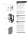
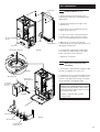
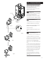
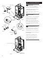
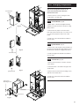
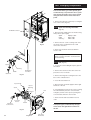
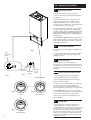
Promax System HE
Wall Mounted Powered Flue Condensing Boiler
Gas Fired Central Heating Unit
Installation and
Servicing Instructions
Please leave these instructions with the user
Natural Gas
Potterton Promax System HE
G.C.No 41 590 69
Guarantee
Your Potterton Promax System HE is
designed and produced to meet all the
relevant Standards.
Potterton provide a 12 month
guarantee on the boiler. The guarantee
operates from the date installation is
completed for the customer who is the
original user.
To maximise the benefit from our
guarantee we urge you to return the
reply-paid guarantee registration.
This does not in any way prejudice
your rights at Common Law. Such
rights between the customer and the
installer or supplier from whom the unit
was purchased remain intact.
Any component or part which becomes
defective during the guarantee period
as a result of faulty workmanship or
material whilst in normal use will be
repaired or replaced free of charge.
The boiler meets the requirements of Statutory
Instrument “ The Boiler (Efficiency) Regulations
1993 No 3083” and is deemed to meet the
requirements of Directive 92/42/EEC on the energy
efficiency requirements for new hot water boilers
fired with liquid or gaseous fuels:Type test for purpose of Regulation 5 certified by:
Notified Body 0086.
Product/Production certified by:
Notified Body 0086.
For GB/IE only.
B.S. Codes of Practice
Standard
BS 6891
BS 5546
BS 5449 Part 1
BS 6798
BS 5440 Part 1
BS 5440 Part 2
BS 7074
BS 7593
Scope
Gas Installation.
Installation of hot water supplies for
domestic purposes.
Forced circulation hot water systems.
Installation of gas fired hot water boilers.
Flues.
Ventilation.
Expansion vessels and ancillary
equipment for sealed water systems.
Treatment of water in domestic hot water
central heating systems.
IMPORTANT - Care must be
exercised when lifting and handling
this product. Seek assistance where
appropriate and avoid stooping.
Protective equipment (e.g. gloves)
should be worn as necessary.
2
Contents
Section
Page
1.0
Introduction
4
2.0
General Layout
5
3.0
Appliance Operation
6
4.0
Technical Data
7
5.0
Dimensions and Fixings
8
6.0
System Details
9
7.0
Site Requirements
12
8.0
Installation
17
9.0
Electrical
23
10.0 Commissioning the Boiler
25
11.0 Fitting the Outer Case
26
12.0 Servicing the Boiler
27
13.0 Changing Components
29
14.0 Fault Finding
38
15.0 Short Parts List
46
3
1.0 Introduction
Potterton declare that no substances
harmful to health are contained in the
appliance or used during appliance
manufacture.
NOTE: This appliance must be installed in
accordance with the manufacturer’s
instructions and the regulations in force, and
only used in a suitably ventilated location.
All systems must be thoroughly flushed
and treated with inhibitor (see Section 6.2).
Read the instructions fully before installing or
using the appliance.
1.1
Description
1. The Potterton Promax System HE is a gas
fired room sealed fan assisted condensing
central heating system boiler.
Fig. 1
Lower Door Panel
2. The maximum output of the boiler is preset at
75,000 Btu/hr. The boiler will automatically adjust
down to 30,000 Btu/hr according to the system
load. If required, the output can be set to 100,000
Btu/hr. Please refer to section 8.7.
3. It is designed for use on Natural Gas (G20).
4. The boiler is suitable for sealed central heating
and domestic hot water systems.
Air Box Door
Data Badge
5. A label giving details of the model, serial
number and Gas Council number is situated on
the rear of the lower door panel (Fig. 1).
6. The boiler data badge is positioned on the air
box door (Fig. 2).
7. The boiler is intended to be installed in
residential / commercial / light industrial E.M.C.
environments on a governed meter supply only.
Fig. 2
8. The boiler must be installed with one of the
purpose designed flues such as the standard
horizontal flue kit, part no 236921.
1.2
Optional Extras
KIT
PART No
FLUE EXTENSION KITS (110/70)
“Benchmark” Log Book
As part of the industry-wide “Benchmark” initiative all Potterton boilers now
include an Installation, Commissioning and Service Record Log Book.
Please read the Log Book carefully and complete all sections relevant to
the appliance and installation. These include sections on the type of
controls employed, flushing the system, burner operating pressure etc.
The details of the Log Book will be required in the event of any warranty
work. Also, there is a section to be completed at each subsequent regular
service visit.
Flue Extension 0.25M
241694
Flue Extension 1M (Use two kits for 2M etc.)
241695
Flue Bend x 2 - 45° (Reduce overall length of flue
by 0.5m when fitting this bend)
241689
Flue Bend - 90° (Reduce overall length of flue
by 1m when fitting each bend)
241687
VERTICAL FLUE (110/70)
Vertical Flue Terminal
242802
Vertical Boiler Connection
242886
VERTICAL FLUE (80/80)
Kit Boiler Connection Twin
4
241692
Flue Extension 0.5M
242757
2.0 General Layout
15
2.1
1
Fig. 6
2
Fig. 5
13/14
3
4
17
6
5
Layout (Figs. 3,4 & 5)
1.
Wall Plate
2.
Flue Elbow
3.
Heat Exchanger
4.
Burner
5.
Air Box
6.
Fan Protection Thermostat
7.
Fan Assembly
8.
Condensate Trap
9.
Gas Tap
10.
Gas / Air Ratio Valve
11.
Electronics Housing
12.
Transformer
13.
Flow Temperature Safety Thermostat - Black
14.
Flow Temperature Thermistor - Red
15.
Flow Switch (dry fire protection)
16.
Circulation Pump
17.
Automatic Air Vent
18.
Pressure Relief Valve
19.
Water Pressure Gauge
20.
Expansion Vessel
10
7
18
11
12
16
9
19
8
20
Fig. 4
Fig. 3
5
3.0 Appliance Operation
3.1
Mains On.
1. Switched Live On: When the switched live
switches on pump overrun occurs.
Pump Overrun
for 1 minute ?
Pump Overrun
Flow
temperature less
than set point and flow
switch made ?
YES
3. Fan Purge: The pump and fan are on while
the spark generator and gas valve are off. After 5
seconds ignition occurs.
YES
YES
5 second
Fan Purge.
YES
2. Pump Overrun: The pump is on while the fan,
spark generator and gas valve are off. If at any
stage during pump overrun the flow temperature
is less than the set point and the flow switch is
made then fan purge occurs. After 1 minute of
pump overrun anti-cycle occurs.
Ignition done
and less than 5
attempts made ?
4. Ignition: The pump, fan, spark generator and
gas valve are on. If a flame is detected then
burner on occurs. If a flame is not detected within
5 seconds and less than 5 ignition attempts have
been made then fan purge occurs. If a flame is
not detected within 5 seconds and 5 ignition
attempts have been made the ignition lockout
occurs.
5. Burner On: The pump, fan and gas valve are
on while the spark generator is off. Flow
temperature is controlled by varying the fan
speed (and thereby the gas rate) to achieve
optimum operation. If the flow temperature is
greater than the set point then pump overrun
occurs. If the TRVs all shut down then anti-cycle
occurs.
Flow temperature
greater than set
point ?
5 second
Ignition Period.
Ignition done and
5 attempts made ?
6. Anti-cycle: The pump, fan, spark generator
and gas valve are switched off. After 3 minutes
pump overrun occurs.
Flame Detected ?
YES
YES
Burner On.
All TRVs
shut down ?
YES
Anti-cycle.
6
Ignition
Lockout.
7. Ignition Lockout: The pump, fan, spark
generator and gas valve are switched off. The
boiler can only be reset by manually using the
thermostat knob.
4.0 Technical Data
Appliance Type
C33
C13
Appliance Category
Heat Input
CAT I 2H
Max
Min
kW
33.76
10.2
Btu/h
115,200
34,840
Heat Output
(Non Condensing 70° C Mean Water Temp)
Max
Min
kW
30.18
9.14
Btu/h
102,980
31,180
Connections
Gas Supply
Central Heating Flow
Central Heating Return
Pressure Relief Discharge
-
copper tails
22mm
22mm
22mm
15mm
Electrical Supply
230V~ 50Hz
(Appliance must be connected to an
earthed supply)
Power Consumption
200W
Condensate Drain
-
1 in BSP
External Fuse Rating
3A
Outercase Dimensions
Overall Height Inc Flue Elbow
Casing Height
Casing Width
Casing Depth
-
1000mm
850mm
490mm
325mm
Internal Fuse Rating (BS 4265)
Fuse (2)
4 AT (Control Board)
Fuse (3)
2 AT (Ignition Board)
Clearances
Water Content
litres
3.5
pints
6.2
(For unventilated compartments see Section 7.5)
Heat Output
(Condensing 40° C Mean Water Temp)
Max
Min
kW
32.61
10.1
Btu/h
111,280
34,520
Max Gas Rate (Natural Gas)
(After 10 Mins)
Btu/hr
102,980
m3/h
2.95
ft3/h
104.2
75,000
2.36
83.3
Inlet Pressure (Natural Gas)
Min
18.1 mbar
Max
22.5 mbar
Both Sides
Above Casing
Below Casing
Front (For Servicing)
Front (In Operation)
5mm Min
200mm Min
200mm Min
500mm Min
5mm Min
Weights
Packaged Boiler Carton
Packaged Flue Kit
Weight Empty
Installation Lift Weight
kg
54.7
3.6
49.4
41
Recommended System
Temperature Drop
Normal
11°C
Condensing 20°C
20°F
36°F
Expansion Vessel - (For Central Heating
only. Integral with appliance)
bar
lb/in2
Min Pre-charge Pressure 0.95
13.6
lb
120.6
8.0
108.9
90.4
Central Heating Primary
Circuit Pressures
Nox Class
5
Horizontal
Flue Terminal
Dimensions
Diameter
Projection
110mm
150mm
bar
3
2.5
1
1-2
Safety Discharge
Max Operating
Min Operating
Recommend Operating
Max Capacity of
CH System
1
14.5
litre
gal
125
27.5
Controls
boiler thermostat, safety thermostat,
flow switch, electronic flame sensing,
temperature protection thermostat &
condensate blockage sensor.
(see Section 10.1)
Injector (Natural Gas)
6.3mm Diameter
Nominal Pre-charge
Pressure
lb/in2
43.5
36.3
10.9
14.5-29
SEDBUK Declaration For
Potterton Promax System HE
The seasonal efficiency (SEDBUK) is 90.9 %
Central Heating Circuit available Pump Head
This value is used in the UK Government’s Standard
Assessment Procedure (SAP) for energy rating of dwellings.
The test data from which it has been calculated have been
certified by 0086.
Pump Head (mbar)
600
500
400
300
200
NOTE: The maximum output of the
boiler is factory set at 22.0kW
(75,000 Btu/hr). This can be altered
to 30.18kW (102,980 Btu/hr)
- see section 8.7.
100
0
0
120
240
360
480
600
720
840
Flow Rate (l/h)
Where flow rates are required in excess of 840 l/h, please refer to page 21.
7
5.0 Dimensions and Fixings
DIMENSIONS
A 850mm
E
3°
(1 in 20)
B 325mm
C 490mm
A
D 125mm Ø Min.
E 150mm
F 125mm
B
360° Orientation
C
D
Tube Ø 110mm
The 3° (1 in 20) fall provided by
the elbow is to allow condensate
to run back to the boiler, for
disposal through the condensate
discharge pipe.
Fig. 7
F
Y
X
3°
(1 in 20)
Fig. 8
8
SIDE FLUE (left and right)
For every 1m of horizontal flue
length, the clearance above the
top of the flue elbow should be
55mm to incorporate the 3°
(1 in 20) fall in the flue from the
terminal to the elbow.
Flue length (Y)
Clearance (X)
up to 1m
55mm
1m - 2m
110mm
2m - 3m
165mm
6.0 System Details
6.1
Hot water
Central
heating
load
Live feed
to pump
Boiler
Boiler
Connections
S/L
N P/F
Switch live from
programmer, etc.
Fig. A
Wiring an extra pump to the pump feed
connection of boiler
Water Circulating Systems
1. The appliance is suitable for fully pumped
sealed systems only.
The following conditions should be observed
on all systems:
• The boiler must not be used with a direct
cylinder.
• Drain cocks should be fitted to all system low
points.
• All gas and water pipes and electrical wiring
must be installed in a way which would not
restrict the servicing of the boiler.
• Air vents should be fitted to all system high
points.
• Best practice recommends that an appropriate
size air separator is fitted, to expel the air from
the system. This will reduce corrosion potential
and maximise the efficiency within the system.
6.2
Treatment of Water Circulating
Systems
• All recirculatory water systems will be subject to
corrosion unless an appropriate water treatment
is applied. This means that the efficiency of
the system will deteriorate as corrosion sludge
accumulates within the system, risking damage
to pump and valves, boiler noise and circulation
problems.
• When upgrading existing systems that exhibit
evidence of sludging, it is advisable to clean the
system prior to treatment in order to remove any
sludge and reduce the likelihood of these
deposits damaging new components.
• When fitting new systems flux will be evident
within the system, which can lead to damage of
system components.
• All systems must be thoroughly drained and
flushed out. The recommended flushing and
cleansing agents are Betz-Dearborn Sentinel
X300 or X400 and Fernox Superfloc Universal
Cleanser which should be used following the
flushing agent manufacturer’s instructions.
• System additives - corrosion inhibitors and
flushing agents/descalers should be suitable for
aluminium and comply to BS7593 requirements.
The only system additives recommended are
Betz-Dearborn Sentinel X100 and Fernox-Copal
which should be used following the inhibitor
manufacturer’s instructions.
Failure to flush and add inhibitor to the
system will invalidate the appliance warranty.
• It is important to check the inhibitor
concentration after installation, system
modification and at every service in accordance
with the manufacturer’s instructions. (Test kits are
available from inhibitor stockists.)
• For information or advice regarding any of the
above contact the Potterton Helpline.
9
6.0 System Details
6.3
Copper
0.5m
Boiler
1. The sizes of flow and return pipes from the
boiler should be determined by normal methods,
according to the requirements of the system. The
connection to the boiler is 22mm (copper tail).
Copper
0.5m
Flow
Return
Copper
1m
Fig. 8a
Pipework
2. Due to space requirements at the rear of the tap
bracket, pipework should comprise of solder
fittings.
3. A 20 °C (36°F) drop in temperature across the
system is recommended for condensing boilers.
Existing radiators may be oversized and so allow
this, but where radiator sizing is marginal it may be
advisable to retain a system temperature drop of
11°C (20°F).
4. In systems using non-metallic pipework it is
necessary to use copper pipe for the boiler Flow
and Return. The copper must extend at least 1
metre from the boiler and include any branches
(Fig. 8a).
6.4
System Controls
1. For optimum operating conditions, the heating
system into which the boiler is installed should
include a control system.
2. Such a system will comprise of a timer control
and separate room or cylinder thermostats as
appropriate.
3. The boiler should be controlled so that it
operates on demand only.
4. Operation of the system under control of the
boiler thermostat & TRV’s only does not produce
the best results.
6.5
Thermal Stores
1. When the Potterton Promax System HE is fitted
in conjunction with a thermal store, jumper 2 must
be removed from the Control PCB, see Fig. 32a
Section 8.7.
10
6.0 System Details
6.6
Double
Check
Valve
System Filling and Pressurising
1. A filling point connection on the central heating
return pipework must be provided to facilitate
initial filling and pressurising and also any
subsequent water loss replacement/refilling.
2. The filling method adopted must be in
accordance with all relevant water supply byelaws and use approved equipment.
Stop Valve
3. Your attention is drawn to: IRN 302 and Byelaw
14.
Mains
CH
Return
Temporary
Hose
Fig. 9
4. The sealed primary circuits may be filled or
replenished by means of a temporary connection
between the circuit and a supply pipe, provided a
‘Listed’ double check valve or some other no less
effective backflow prevention device is
permanently connected at the inlet to the circuit
and the temporary connection is removed after
use (Fig. 9).
6.7
1. The appliance expansion vessel is pre-charged
to 1 bar (10 lb/in2). Therefore, the minimum cold
fill pressure is 1 bar. The vessel is suitable for
correct operation for system capacities up to 125
litres (27.5gal). For greater system capacities an
additional expansion vessel must be fitted - refer
to BS 7074 Pt 1.
Pressure Relief
Valve
6.8
Fig. 10
Expansion Vessel
Expansion Vessel
removed for clarity
Pressure Relief Valve (Figs. 10 & 11)
1. The pressure relief valve is set at 3 bar,
therefore all pipework, fittings, etc. should be
suitable for pressures in excess of 3 bar.
2. The pressure relief discharge pipe should be
not less than 15mm dia, run continuously
downward, and discharge outside the building,
preferably over a drain. It should be routed in
such a manner that no hazard occurs to
occupants or causes damage to wiring or
electrical components. The end of the pipe should
terminate facing down and towards the wall.
Discharge Pipe
3. The discharge must not be above a window,
entrance or other public access. Consideration
must be given to the possibility that boiling
water/steam could discharge from the pipe.
Fig. 11
11
7.0 Site Requirements
7.1
490mm
5mm Min
5mm Min
200mm
Information
WARNING - Check the information on the data
plate is compatible with local supply conditions.
1. The installation must be carried out by a CORGI
Registered Installer or other registered competent
person and be in accordance with the relevant
requirements of the current GAS SAFETY (Installation
and Use) REGULATIONS, the BUILDING REGULATIONS
(Scotland)(Consolidation), the LOCAL BUILDING
REGULATIONS, the current I.E.E. WIRING REGULATIONS
and the bye laws of the LOCAL WATER UNDERTAKING.
Where no specific instruction is given reference should
be made to the relevant BRITISH STANDARD
CODES OF PRACTICE. For Ireland install in
accordance with IS 813 “INSTALLATION OF GAS
APPLIANCES”. Reference should also be made to
BRITISH GAS GUIDANCE NOTES FOR THE INSTALLATION OF
DOMESTIC GAS CONDENSING BOILERS.
850mm
7.2
B.S. Codes of Practice
Standard
BS 6891
BS 5546
BS 5449 Part 1
BS 6798
BS 5440 Part 1
BS 5440 Part 2
BS 7074
BS 7593
200mm
Fig. 12
Scope
Gas Installation.
Installation of hot water supplies for
domestic purposes.
Forced circulation hot water systems.
Installation of gas fired hot water boilers.
Flues.
Ventilation.
Expansion vessels and ancillary
equipment for sealed water systems.
Treatment of water in domestic hot water
central heating systems.
WARNING - The addition of anything that may
interfere with the normal operation of the appliance
without the express written permission of Potterton
could invalidate the appliance warranty and infringe
the GAS SAFETY (Installation and Use) REGULATIONS.
7.3
Clearances (Figs. 12 &13)
1. A flat vertical area is required for the installation
of the boiler.
3°
(1 in 20)
2. These dimensions include the necessary
clearances around the boiler for case removal,
spanner access and air movement. Additional
clearances may be required for the passage of
pipes around local obstructions such as joists
running parallel to the front face of the boiler.
3. For unventilated compartments see Section 7.5.
7.4
500mm
1. The boiler may be fitted to any suitable wall with
the flue passing through an outside wall or roof and
discharging to atmosphere in a position permitting
satisfactory removal of combustion products and
providing an adequate air supply. The boiler should
be fitted within the building unless otherwise
protected by a suitable enclosure i.e. garage or
outhouse. (The boiler may be fitted inside a
cupboard - see Section 7.5).
For Servicing
Purposes
5mm
Fig. 13
12
In Operation
Location
NOTE: Due to the nature of the boiler a plume of
water vapour will be discharged from the flue. This
should be taken into account when siting the flue
terminal.
325mm
2. If the boiler is sited in an unheated enclosure
then it is recommended to incorporate in the system
controls a suitable device for frost protection.
3. If the boiler is fitted in a room containing a bath or
shower reference must be made to the current
I.E.E. WIRING REGULATIONS and BUILDING
REGULATIONS. If the boiler is to be fitted into a
building of timber frame construction then reference
must be made to the Institute of Gas Engineers
document UP 7.
7.0 Site Requirements
7.5
Ventilation of Compartments
1. Where the boiler is installed in a cupboard or
compartment, no air vents are required for cooling
purposes providing that the minimum dimensions
below are maintained.
Sides
Top
Bottom
Front
25mm
200mm
200mm
100mm
2. Any compartment should be large enough to
house the boiler only.
7.6
Gas Supply
1. The gas installation should be in accordance
with BS6891.
2. The connection to the appliance is a 22mm
copper tail located at the rear of the gas service
cock (Fig. 15).
3. Ensure that the pipework from the meter to the
appliance is of adequate size.
(22mm recommended at the appliance). Do not
use pipes of a smaller diameter than the boiler
gas connection.
7.7
Electrical Supply
1. External wiring must be correctly earthed,
polarised and in accordance with current I.E.E.
WIRING REGULATIONS.
2. The mains supply is 230V ~ 50Hz fused at 3A.
Gas Service Cock
NOTE: The method of connection to the
electricity supply must facilitate complete
electrical isolation of the appliance. Connection
may be via a fused double-pole isolator with a
contact separation of at least 3mm in all poles
and servicing the boiler and system controls
only.
Fig. 15
7.8
Condensate Drain
NOTE: Ensure the discharge of condensate
complies with any national or local regulations
in force.
1. The condensate outlet terminates in a 1” BSP
nut and seal for the connection of 21.5mm (3/4in)
plastic overflow pipe which should generally
discharge internally into the household drainage
system. If this is not possible, discharge into an
outside drain is acceptable.
2. The pipe should run internally as much as
possible and with a 10° (1 in 6) fall to dispose of
condensate quickly to avoid freezing.
13
7.0 Site Requirements
7.9
Flue
NOTE: Due to the nature of the boiler a plume
of water vapour will be discharged from the
flue. This should be taken into account when
siting the flue terminal.
1. The following guidelines indicate the general
requirements for siting balanced flue terminals.
Recommendations for flues are given in BS 5440
Pt.1.
2. If the terminal discharges onto a pathway or
passageway, check that combustion products will
not cause a nuisance and that the terminal will
not obstruct the passageway.
3. Take into consideration the effect the plume of
vapour may have on neighbours when siting the
flue.
S
5. If a terminal is less than 2 metres (783/4 in)
above a balcony, above ground or above a flat
roof to which people have access, then a suitable
terminal guard must be provided.
L
Q
K
B,C
N
G
G
D
R
P
M
D
J
A
A
E
F
H,I
F
G
Fig. 17
Likely flue positions requiring
a flue terminal guard
Terminal Position with Minimum Distance (Fig. 17)
Directly below an openable window, air vent or any other
ventilation opening.
B Below gutter, drain/soil pipe.
C Below eaves.
D Below a balcony/car port roof.
E From vertical drain pipes and soil pipes.
F From internal or external corners.
G Above adjacent ground or balcony level.
H From a surface facing a terminal.
I Facing a terminals.
J From opening (door/window) in carport into dwelling.
K Vertically from a terminal on the same wall.
L Horizontally from a terminal on the same wall.
M Above an opening, air brick, opening window etc.
N Horizontally to an opening, air brick, opening window etc.
Vertical Flues - minimum distance to edge of terminal
P Above the roof level (to base of terminal).
Q From adjacent wall to flue.
R From adjacent opening window.
S From another terminal.
(mm)
A
14
300
150
200
200
150
300
300
600
1200
1200
1500
300
300
300
mm
300
300
1000
600
NOTE: The distance from a fanned draught
appliance terminal installed parallel to a
boundary may not be less than 300mm in
accordance with the diagram below
Terminal
Assembly
300 min
Top View Rear Flue
Fig. 16
Property Boundary Line
7.0 Site Requirements
7.10
Flue Dimensions
See Section 1.2. The standard horizontal flue kit
allows for flue lengths between 270mm (105/8”)
and 800mm (32”) from elbow to terminal
(Fig. 18).
m
0m
80
m
0m
27
The maximum permissible equivalent flue
length is: 4 metres (Fig. 18a).
NOTE: Each additional 45° of flue bend will
account for an equivalent flue length of 0.5m.
eg. 45° = 0.5m,
90° = 2 x 45° = 1m etc.
7.11
Terminal Guard (Fig. 19)
1. When codes of practice dictate the use of
terminal guards, they can be obtained from most
Plumbers’ and Builders’ Merchants.
Fig. 18
1m
2. There must be a clearance of at least 50mm
between any part of the terminal and the guard.
0.5m
0.5m
0.5m
Fig. 18a
Pictorial examples of flue runs where EQUIVALENT flue length equals 4m
3. When ordering a terminal guard, quote the
appliance model number.
4. The flue terminal guard should be positioned
centrally over the terminal and fixed as
illustrated.
7.12
Vertical Flue
1. Only a flue approved with the Potterton
Promax System HE can be used.
Fig. 19
15
Standard Flue
7.0 Site Requirement
C
7.13
Flue options
Concentric
The maximum equivalent lengths are 4m
(horizontal) or (vertical). There lengths exclude the
standard elbow and flue/terminal assembly
(horizontal) and terminal assembly (vertical).
Twin Flue
The total maximum equivalent flue length is 150m.
NOTE: Each 1m of flue duct should be calculated
as 2m.
D
B
Any additional “in line” bends in the flue system
must be taken into consideration. Their equivalent
lengths are:
A
Concentric Pipes: 45° bend
93° bend
0.5 m
1.0 m
Twin Flue Pipe:
1.3 m
2.6 m
4.8 m
9.6 m
45° bend (air duct)
45° bend (flue duct)
90° bend (air duct)
90° bend (flue duct)
Detailed examples of equivalent flue length
calculation are given in the Installation Guidance
Notes for each flue system type.
(Documents 243501 and 243502 for concentric and
twin pipe respectively).
J
K
L
Key Accessory
Size
Baxi Code
Number
C
N
M
H
E
H
16
G
F
Concentric Flue System 110mm diameter
A
Straight extension kit
1000mm
500mm
250mm
B
Bend kit
93°
C
Bend kit (pair)
45°
D
Horizontal flue terminal
Clamp
110mm
241695
241694
241692
241687
241689
243013BAX
243014BAX
Twin Flue System 80mm diameter
E
Straight extension kit
1000mm
500mm
250mm
F
Bend kit
90°
G
Bend kit (pair)
45°
238690
238692
238694
246139
246138
Universal Vertical Flue Kits
H
Twin flue adaptor kit
J
Vertical flue terminal
K
Universal roof tile
25°/50°
L
Roof cover plate kit
M
Flat roof flashing
N
Boiler connection vertical concentric
Clamp
80mm
242757
242802
243015
243131
243016BAX
242886
238684
8.0 Installation
Fixing Template
Check Site Requirements (section 7.0) before
commencing.
NOTE : FOR EACH 1m OF HORIZONTAL FLUE ADD 55mm OF CLEARANCE ABOVE THIS LINE
37mm
CENTRE FOR DIA.150mm (6") HOLE
CENTRE LINE OF FLUE
WALL THICKNESS UPTO 227mm (9")
CENTRE FOR DIA. 125mm (5") HOLE
TO 750mm (30")
WALL THICKNESS UPTO 227mm (9")
CENTRE LINE OF FLUE
AT 3 DEGREES
AT 3 DEGREES
8.1
Initial Preparation
APPLIANCE OUTLINE
The gas supply, gas type and pressure must
be checked for suitability before connection
(see Section 7.6).
NOTE: If the boiler is to be pre-plumbed,
follow both these instructions and those on
the boiler pack.
PROMAX SYSTEM HE
BOILER
BOILER CENTRE LINE
1. Remove the fixing template (Fig. 20) from the
fixing carton.
2. After considering the site requirements
(see Section 7.0) position the template on the
wall ensuring it is level both horizontally and
vertically.
MINIMUM CLEARANCE 5mm EACH SIDE
3. Mark the position of the top centre hole for the
wallplate.
GENERAL AREA FOR
ELECTRICAL SUPPLY
4. Mark the condensate discharge pipe area.
CONDENSATE
GAS
DRAIN
SUPPLY
FLOW
RETURN
PRESSURE
RELIEF
FIXING TEMPLATE PART No. 5106702p
5. Mark the centre of the flue hole (rear exit). For
side exit, mark as shown. If required, mark the
position of the gas and water pipes. Remove the
template.
6. Cut the hole for the flue (minimum diameter
125mm) (see table opposite for wall thickness
flue diameter’s).
Fig. 20
7. Drill and plug the wall as previously marked.
Secure the wallplate to the wall by the top centre
hole.
Wall Thickness
Flue Hole ø
up to 227mm
125mm core drill
up to 750mm
150mm core drill
up to 1200mm
175mm core drill
8. Ensuring the wallplate is level both
horizontally and vertically, drill and plug the
remaining 4 securing positions at the top and
bottom through the wallplate. Utilising the slots
available ensure the wallplate is square and
secure to the wall.
9. Connect the gas, water and the pressure relief
discharge pipes to the valves on the support
bracket using the copper tails supplied. Ensure
the sealing washers are fitted correctly to the
water connections.
Plastic Flushing Tube
10. Loosely route the condensate discharge pipe
to the area previously marked.
8.2
Flushing
1. Insert a tube into the valve outlet furthest from
the filling loop (Fig. 21).
Fig. 21
2. Flush thoroughly (see System Details, Section
6.0).
17
8.0 Installation
8.3
Preparing The Boiler
1. Remove the outer carton.
2. Remove the internal packaging.
3. Lift the outercase upwards and remove
(Fig. 23).
Potterton declare that no substances
harmful to health are contained in the
appliance or used during appliance
manufacture.
Fig. 23
18
8.0 Installation
Top Hooks
8.4
Fitting The Boiler (Fig. 24)
1. Remove the tape from the tap rail on the
support bracket and fit the central heating return
filter (Fig. 25).
2. Lift the boiler using the lower edges of the
combustion box.
3. Lift the boiler over the support bracket and
engage onto the top hooks.
4. To gain access to the connections between
boiler and valves, release the facia securing
screws (1/4 turn) and hinge down the facia box.
Facia Securing
Screws
Tap Rail
Support Bracket
Facia Box
Fig. 24
Flue Products Exhaust
5. Make the gas connection first. This will
centralise the boiler. The gas sealing washer is an
integral part of the gas tap.
6. Insert the fibre sealing washers between the
valve outlet face and the flange on the copper
bends of the water circuit connections.
7. Tighten the connections.
8.5
Making the Condensate Drain
Connection
1. Connect the condensate drain using the 1” BSP
nut and seal supplied. (see section 7.8.)
Fig. 25a
2. For better access, loosen the left hand electrical
box/transformer mounting plate securing screws
and remove the right hand securing screw. Slide
the electrical box to the right (Fig. 25b).
Mounting Plate
Right Hand
Securing Screw
Left Hand
Securing
Screws
NOTE: To ensure the correct operation and
integrity of the condensate drainage system
- Carefully pour approximately 1 litre of water
into the flue products exhaust, at the top of the
heat exchanger (Fig. 25a).
Fig. 25b
Check the condensate drain for leaks,
blockage and fall.
Tap Rail
Fig. 25
Gas Connection
Central Heating
Return Filter
19
8.0 Installation
Wall Thickness
8.6
Fitting The Flue
Before fitting the flue, check the condensate
drain integrity (see section 8.5).
3°
(1 in 20)
IMPORTANT: The flue should always be
installed with a 3° (1 in 20) fall from terminal to
elbow, to allow condensate to run back to the
boiler.
HORIZONTAL FLUE
1. The standard flue is suitable for lengths 270mm
minimum to 800mm maximum (measured from the
edge of the flue elbow outlet).
Rear Flue: maximum wall thickness - 630mm
Side Flue: maximum wall thickness - 565mm (left or right)
X
2. For rear exit - measure the wall thickness
(Fig. 26) and to this dimension add 245mm. This
dimension to be known as (X).
i.e.
(X) = wall thickness + 245mm
360° Orientation
3. Take the flue and mark off (X) from the terminal
end as indicated in the diagram (Fig. 27).
Check your dimensions.
Y
Edge of Wall Plate to Wall
Wall Thickness
4. For left hand exit - measure the distance from
the edge of the wall plate to the inner face of the
wall (Fig. 26) and to this dimension add the wall
thickness + 275mm. This dimension to be known
as (Y).
i.e.
(Y) = wall plate to wall + wall thickness + 275mm
Fig. 26
Waste
The flue tubes are fixed together. Cut through both
tubes whilst resting the flue on the semi-circular
packing pieces. Deburr both tube ends.
(Y) = Left Exit
(Z) = Right Exit
(X) = Rear Exit
5. Take the flue and mark off (Y) from the terminal
end as indicated (Fig. 27).
6. For right hand exit - measure the distance from
the edge of the wall plate to the inner face of the
wall and to this dimension add the wall thickness +
350mm. This dimension to be known as (Z).
i.e.
(Z) = wall plate to wall + wall thickness + 350mm
Flue
Fig. 27
7. Take the flue and mark off (Z) from the terminal
end as indicated (Fig. 27).
Inner Flue Support Bracket
Check your dimensions.
The flue tubes are fixed together. Cut through both
tubes whilst resting the flue on the semi-circular
packing pieces. Deburr both tube ends.
Fig. 27a
20
IMPORTANT: Check all measurements before
cutting. When cutting ensure the cut does not
interfere with the inner flue support bracket
(Fig. 27a).
8.0 Installation
8.6
Inner Flue Support Bracket
Fitting the Flue (Cont)
6. Ensure the inner flue support bracket is
positioned in the flue (Fig. 28).
7. Engage the flue into the flue elbow using soap
solution to ease the engagement ensuring the
flue is assembled as shown (Fig. 29).
Fig. 28
8. Place the gasket over the flue exit on the
boiler.
9. Slide the flue assembly through the hole in the
wall.
Flue
10. Engage the elbow on to the flue connection
on top of the boiler. Secure with the four screws
supplied in the kit.
11. Make good between the wall and air duct
outside the building ensuring the 3° drop between
the terminal and elbow.
Flue Elbow
12. The flue trim should be fitted once the
installation is complete and the flue secure. Apply
a suitable mastic to the inside of the trim and
press against the wall finish, making sure the
brickwork is dust free and dry (Fig. 30). If
necessary fit a terminal guard (see section 7.11).
Gasket
VERTICAL FLUEING
1. Only a flue approved with the Potterton Promax
System HE Boiler can be used.
Fig. 30
Flue Trim
Fig. 29
21
8.0 Installation
8.7
Making The Electrical Connections
WARNING: This appliance must be earthed
1. The electrical connections are on the left hand
side of the unit behind the facia inside the
electrical box.
2. Undo the two screws securing the electrical box
cover and remove the cover (Fig. 31).
3. Undo the two screws securing the SL, , N, PF
cable clamp and place to one side (Fig. 32).
4. The boiler is factory set to give a maximum
output of 22.0 kW (75,000 Btu/hr). The Control
PCB jumper positions are as follows:
J1 In
Jumper 1
Electrical Box
Cover
Jumper 2
Jumper 3
Fig. 32a
Fig. 31
J2 In
J3 In
If the installation requires a greater output to
achieve the desired room temperature, this can be
increased to 31.18 kW (103,000 Btu/hr) and the
boiler can be adjusted as follows:
a) Draw the control PCB forwards out of the
electrical box (the control PCB is the right
hand board).
b) Remove all three jumpers.
c) Replace the PCB and continue with the
installation.
If the boiler is to be used in conjunction with a
Thermal Store, the boiler can be adjusted as
follows (Fig. 32a):
a) Draw the control PCB forwards out of the
electrical box (the control PCB is the right
hand board).
b) Remove jumper no 2.
c) Replace the PCB and continue with the
installation.
5. Lay the cable through the cable clamp to gauge
the length of cable required when it is connected to
the 4-way terminal block (Fig. 32).
Control Board
Fig. 32
6. Connect the (S/L), (N) and ( ) wires to the
4-way terminal block and refit the cable clamp
(Fig. 33).
Cable Clamp
S/L = Switched live to the Boiler from the
System Controls.
P/F = Optional Pump Feed, only need
be used when fitting an additional
external pump on a full TRV system
without a bypass fitted.
S/L
N
P/F
7. The P/F connection should be used as a
external pump live feed when fitting an extra pump
to the system boiler on a fully TRV’d system with
no bypass. If the S/L connection is used, this will
not protect the external pump if all TRV’s shut
down in a full TRV system.
8. Check the electrical installation for;
earth continuity, short circuits, resistance to earth,
correct polarity and fuse failure.
9. Replace the electrical box cover and secure.
Fig. 33
22
9.0 Electrical
9.1
Schematic Wiring Diagram
Control
PCB
bk bk
b bk
w g br
br
r
DC
Dry Fire
Fan
Flow Switch
r
Ignition
PCB
b
br
w
r
Gas
Valve
bk
Earth
Electrode
b
Detection Electrode
Condensate
Trap
bk
br
b
br
br
Transformer
g/y
Thermistor
Casing
Stat
br
b
bk
N
Spark
Electrode
User PCB
r
bk
g/y
g/y
oooooooo
b
bk
L
Pump
Overheat
Stat
S/L
N P/F
Mains Optional
Input Pump Feed
Key To Wiring Colours
b - Blue
r - Red
bk - Black
g - Green
w - White
g/y- Green/Yellow
br - Brown
y - Yellow
v - Violet
o - Orange
23
9.0 Electrical
9.2
Illustrated Wiring Diagram
r
br
w
g
b
Flow Switch
Fan
bk
Interface
PCB
bk
Sensing
Electrode
r
g
b
Flow
Temperature
Thermistor
w br
Control
PCB
w
w
w b y r
v g o bk
Condensate
Trap
g/y
bk
br
Ignition
PCB
Fan Protection
Thermostat
Connector
with blue label
b
r
bk
r
br
bk
r
bk
Safety
Thermostat
bk
br
b
br
b
br
bk
Gas
Valve
b
Transformer
Earth
br
Spark and
Earth Electrode
Wiring Key
b
bk
br
r
w
g/y
v
y
o
24
- Blue
- Black
- Brown
- Red
- White
- Green/Yellow
- Violet
- Yellow
- Orange
g/y
Mains
Input
g/y
b
b
g/y
Earth
br
b
Pump
g/y
10.0 Commissioning the Boiler
10.1
Commissioning the Boiler
1. Reference should be made to BS 5449
Section 5 when commissioning the boiler.
2. Flush the whole system using a suitable
flushing agent (see Section 6.2) and vent the
radiators. Check for water leaks.
3. Refill the system with inhibitor following the
inhibitor manufacturer’s instructions and BS 7593
Code of Practice for Treatment of Water in
Domestic Hot Water Central Heating Systems
(see Section 6.2).
4. Turn the gas supply on and purge the system
according to BS 6891.
5. Turn the gas service cock anticlockwise to the
ON position and check for gas soundness up to
the gas valve.
Control Knob
6. Turn the boiler control knob fully clockwise to
‘HIGH’ (Fig. 34) and run the system and check
the boiler for correct operation.
NOTE: The boiler is self-regulating and the
gas rate will modulate between inputs of
33.76kW and 10.2kW dependent upon the
system load. The input is factory set at
24.5kW and can be altered to 33.76kW - see
section 8.7. No adjustment of the gas valve
is permissible.
HIGH
LOW
7. With the system cold and all controls calling
for heat check the gas pressure at the inlet
tapping of the gas valve (Fig. 35). The pressure
must be a minimum of 18.1 mbar.
Fig. 34
Gas Valve
Expansion Vessel
removed for clarity
IN
OUT
DO NOT check gas pressure here
Fig. 35
Inlet Gas Pressure Test Point
25
11.0 Fitting the Outer Case
11.1
Fitting The Outer Case
1. Position the outercase on the chassis,
ensuring that the four slots in the side flanges
align with the hooks on the chassis (Fig. 36).
2. Insert the two fixing screws into the sides of
the chassis (Fig. 37).
3. Close the door against the retaining magnets
(Fig. 37).
4. Carefully read and complete all sections of
the “Benchmark” Installation, Commissioning
and Service Record Log Book that are relevant
to the appliance and installation. The details of
the Log Book will be required in the event of any
warranty work. The Log Book must be handed
to the user for safe keeping and each
subsequent regular service visit recorded.
Fig. 36
5. The “Important Ventilation Information” label
can be removed unless the appliance is
installed in an unventilated compartment.
6. Instruct the user in the operation of the boiler
controls. Hand over the Users Operating,
Installation and Servicing Instructions and the
Log Book, giving advice on the necessity of
regular servicing.
7. Advise the user that they may observe a
plume of vapour from the flue terminal, and that
it is part of the normal operation of the boiler.
IMPORTANT: This boiler is fitted with an
aluminium alloy heat exchanger.
It is important that the system is thoroughly
flushed in accordance with BS 7593 and that
one of the following inhibitors is used:
BETZ DEARBORN SENTINEL X100
FERNOX COPAL
Refer to inhibitor manufacturer’s instructions
for correct use. Failure to comply with this
requirement will invalidate the appliance
warranty.
It is also important to check the inhibitor
concentration after installation, system
modification and at every service.
Date Boiler Installed
/
/
Inhibitor Used
Fig. 37
8. This label is located on the electrical box front
cover on the boiler. Detail of system treatment
should be added for future reference.
26
12.0 Servicing the Boiler
12.1
Annual Servicing
IMPORTANT: When servicing ensure that both the
gas and electrical supplies to the boiler are isolated
before any work is started.
When the boiler control knob is switched off the
control PCB remains live. Therefore it is important
to isolate the electrical supply.
Hazardous materials are not used in the
construction of Potterton products, however
reasonable care during service is recommended.
When replacing the combustion box door after
servicing it is essential that the retaining screws
are tightened fully.
1. For reasons of safety and economy, it is
recommended that the boiler is serviced annually.
2. After servicing, complete the relevant section
of the “Benchmark” Installation, Commissioning
and Service Record Log Book. This should be in
the possession of the user.
Air Box Door Panel
3. Ensure that the boiler is cool.
4. Ensure that both the gas and electrical
supplies to the boiler are isolated.
5. Remove the outercase and lower door panel
(see Fitting the Outercase, Section 11.0).
Fig. 39
Lead Terminals
6. Release the four 1/4 turn screws securing the
air box door panel and remove the door (Fig. 39).
7. Disconnect the three lead terminals from the
combustion box door taking note of their positions
(Fig. 39).
8. Undo the four screws securing the combustion
box door and remove the door (Fig. 40).
9. Visually check for debris/damage and clean or
replace if necessary the following:
a)
b)
c)
d)
e)
f)
g)
Burner (Fragile - handle with care).
Heat exchanger fins.
Fan compartment (Check also for condensate leaks).
Insulation.
Door seals.
Electrodes.
Check condensate trap for debris. NOTE:
Remove the trap drain plug and place a
vessel underneath to catch the condensate
(care should be taken as this could be hot).
Clean the trap and refit the drain plug.
h) Top of heat exchanger.
NOTE: General cleaning can be undertaken
using a vacuum. However debris should
only be gently blown off the burner skin
due to its fragile nature.
Combustion Box
Door Panel
Fig. 40
10. Check system pressure is between 1 and 2.5
bar.
27
12.0 Servicing the Boiler
12.1
Annual Servicing (Cont)
11. To clean the heat exchanger and burner
proceed as follows:
a) Disconnect the electrical leads to the fan
component protection sensor (Fig. 41).
b) Loosen the screw retaining the gas injector
pipe at the venturi (Fig. 41).
c) Undo the two wing nuts to disconnect the fan
(Fig. 41).
Injector Pipe
d) Remove the fan and disconnect the electrical
supply to it (Fig. 41).
e) Remove the gas injector pipe from the gas
valve (push-fit) (Fig. 41).
Injector Pipe
Retaining Screw
Securing Nut
Fan
Condensate
Trap
Protection
Sensor Leads
Fig. 41
Electrical Supply
Sensor
Leads
Wing Nuts
f) Undo the condensate trap securing nut, lock
nut and the condensate drain pipe. Remove the
condensate trap and disconnect the sensor
leads (Fig. 42).
g) Remove the two screws securing the burner
and remove the burner. Visually inspect the
internal burner baffle for obstruction.
NOTE: The burner skin is fragile - handle
with care. Clean and if necessary replace the
burner (Fig. 43) (see note, page 26).
Lock Nut
Condensate
Drain Pipe
Fig. 42
Central Insulation Panel
h) Loosen the two screws retaining the heat
exchanger support bracket and slide to the left
to remove (Fig. 43).
i) Remove the four screws securing the heat
exchanger/combustion box base and withdraw
the base.
j) Lower the central insulation panel and check
condition (Fig. 43). Replace the lower insulation
pad if necessary.
Burner
Combustion
Box Base
Heat Exchanger
Support Bracket
Combustion Box Base
Securing Screws
Burner Securing
Screws
28
Fig. 43
k) Ensure the heat exchanger fins are clear of
any obstruction.
l) Check condition of all seals.
m) Reassemble in reverse order.
12. Complete the relevant section of the
“Benchmark” Installation, Commissioning and
Service Record Log Book and hand it back to
the user.
13.0 Changing Components
13.1
Changing Components
IMPORTANT: When changing components
ensure that both the gas and electrical
supplies to the boiler are isolated before any
work is started.
When the boiler control knob is switched off
the control PCB remains live. Therefore it is
important to isolate the electrical supply.
Heat Exchanger
Manifold
Hazardous materials are not used in the
construction of Potterton products, however
reasonable care during service is
recommended.
When replacing the combustion box door after
changing components it is essential that the
retaining screws are tightened fully.
1. Remove the outer case and lower door panel
(see “Fitting the Outercase” Section 11.0).
Drain Point
Tube
Fig. 44
2. Isolate the water circuit and drain the system
as necessary. There are 3 drain points:
a)
b)
c)
Flow Valve
Heat Exchanger Manifold
Return Valve
NOTE: Do not use the Pressure Relief Valve to
drain the circuit.
Air Vent
Sealing Washer
Fig. 45
NOTE: When reassembling always fit new ‘O’
rings, ensuring their correct location on the
spigot. Green “O” rings are used for gas joints
and Black “O” rings for water joints. Use Greasil
4000 (Approved Silicone Grease).
3. After changing a component re-commission the
boiler where appropriate and check the inhibitor
concentration (see Section 6.2 and 10.1).
The air vent, flowswitch, thermistor, safety
thermostat and expansion vessel can be
accessed after removal of the outer case.
13.2
Automatic Air Vent (Fig. 45)
1. Drain the boiler.
2. Undo the air vent from the return pipe and
retain the sealing washer.
3. Remove the air vent.
4. Fit the new air vent and reassemble in reverse
order.
29
13.0 Changing Components
Flowswitch
13.3
Flowswitch (Fig. 46)
Flow Pipe
1. Drain the boiler (see Section 13.1 paragraph 2 & 3).
2. It may be necessary to remove the expansion
vessel (see Section 13.5).
3. Remove the clip securing the flow pipe to the
flowswitch.
Fig. 46
4. Remove the two screws securing the flow
switch to the boiler.
Clip
5. Disconnect the inline electrical connection.
6. Remove the flowswitch.
7. Fit the new flowswitch and reassemble in
reverse order.
8. Recommission the boiler and check the
inhibitor concentration (see Section 6.2 and 10.1).
13.4
Flow Temperature Thermistor and
Safety Thermostat (Fig. 47)
1. The procedure is the same for both the
thermistor and the safety thermostat.
2. Remove the electrical connections from the
sensor.
3. Unscrew the sensor from the pipe.
Expansion Vessel
Connection
4. Fit the new thermistor or safety thermostat and
reassemble in reverse order.
13.5
Expansion Vessel (Fig. 48)
1. Drain the boiler (see Section 13.1 paragraph 2 & 3).
Fig. 47
2. Loosen the securing screw at the base of the
expansion vessel.
3. Whilst supporting the vessel undo the
expansion vessel connection and retain the
sealing washer.
4. Remove the expansion vessel.
5. Fit the new expansion vessel and reassemble
in reverse order.
13.6
Re-pressuring Expansion vessel
1. The charge pressure is 1.0 bar.
2. Close the central heating flow and return
isolating valves.
Expansion Vessel
Fig. 48
30
Expansion Vessel
Securing Screw
3. Drain the boiler (see Section 13.1 paragraph 2 & 3).
4. The “Schraeder” valve is positioned centrally at
the side of the appliance. Pressurise to 1.0 bar.
5. Open the isolating valves and recharge the
system to between 1.0 bar and 2.5 bar. Vent the
system as necessary.
13.0
Changing Components
The Pump, interface PCB, pressure gauge
and pressure relief valve can be accessed
after hinging down the facia box.
1. Release the facia securing screws (1/4 turn)
and hinge down the facia box.
13.7
Pump (Fig. 49)
Facia Box
1. If only the head needs replacing. A standard
Grundfos UPS 15-60 pump head is
interchangeable (see section 13.13 for details).
2. This must be switched to setting No 3 (Fig. 50).
13.8
Pump (Complete) (Fig. 51)
1. Drain the boiler (see Section 13.1 paragraph 2 & 3).
Facia Securing
Screws
2. Unplug the wiring harness from the pump.
3. Remove the four screws retaining the pump
backplate to the hydraulic manifold.
Fig. 49
4. Remove the pump.
5. Fit the new pump and reassemble in reverse
order.
Pump Setting
13.9
Pump (Head Only) (Fig. 52)
Fig. 50
1. Drain the boiler (see Section 13.1 paragraph 2 & 3).
2. Unplug the wiring harness from the pump.
3. Remove the four socket head screws securing
the pump head and separate it from the housing.
Fig. 51
4. Remove the screws retaining the pump
electrical covers on the original and replacement
heads.
5. From the replacement UPS 15-60 pump head
remove the strain relief cable gland and discard.
6. Remove the plug connector from the old pump
head and wire it into the UPS 15-60 pump head.
7. Replace the electrical cover to the new pump
head and assemble with the electrical box at
6 o’clock to the housing.
Fig. 52
8. Check that the pump has been switched to
setting No 3 (Fig. 50) and reconnect the wiring
harness plug.
31
13.0
Changing Components
13.10 Interface PCB
Interface PCB
Electrical
Connections
1. Pull the control knob off the spindle and
remove the securing nut and washer (Fig. 53).
2. Lift the PCB from the facia box and remove
the electrical connections (Fig. 54).
3. Fit the new PCB and reassemble in reverse
order.
Fig. 54
13.11 Pressure Gauge
Facia Box
1. Drain the boiler (see Section 13.1 paragraph 2 & 3).
Fig. 55
2. Undo the nut retaining the capillary in the
connection at the return pipe (Fig. 56).
3. Depress the two lugs on either side of the
pressure gauge and feed through facia (Fig. 57).
4. Fit new pressure gauge and reassemble in
reverse order.
Securing
Nut
Control
Knob
Washer
13.12 Pressure Relief Valve (Fig. 58)
Capillary
Lug
1. The pressure relief valve is positioned on the
hydraulic manifold at the back of the pump.
Fig. 57
2. Drain the boiler (see Section 13.1 paragraph 2 & 3).
Pressure Gauge
Fig. 53
3. Disconnect the union between the valve and
the discharge pipe.
Return Pipe
4. Slacken the screw retaining the valve.
Fig. 56
5. Pull the valve upwards to disengage it.
6. Fit the new pressure relief valve and
reassemble in reverse order.
Pressure Relief Valve
Fig. 58
32
Expansion Vessel
removed for clarity
13.0 Changing Components
The control and ignition boards can be
accessed on the removal of the main
electrical box cover.
Electrical Box
Cover
1. Remove the two screws securing the main
electrical box cover (Fig. 59).
13.13 Control Board (Fig. 60)
Fig. 59
1. Slide out the control board (right hand side)
and disconnect the electrical connections noting
their positions.
2. Check if the two jumper connections have
been removed from the board - see section 8.7. If
so, remove the jumpers from the new control
board.
3. Fit the new control board and reassemble in
reverse order.
13.14 Ignition Board (Fig. 61)
Fig. 60
Control Board
1. Remove the control board, (13.5) and slide out
the ignition board (left hand side) and disconnect
the electrical connections noting their positions.
2. Fit the new ignition board and reassemble in
reverse order.
13.15 Transformer (Fig. 62)
1. Remove the transformer connection from the
control board.
2. The transformer is mounted to the right of the
electrical box.
Fig. 61
Ignition Board
3. Remove the two transformer mounting screws
and remove the transformer.
4. Fit the new transformer and reassemble in
reverse order.
Transformer
Mounting Screws
Transformer
Fig. 62
33
13.0 Changing Components
The fan and venturi, gas valve, injector pipe,
condensate trap, fan protection sensor, spark
and sensing electrodes can be accessed and
changed on the removal of the airbox door
panel.
1. Remove the airbox door panel by loosening the
four 1/4 turn screws (Fig. 63).
13.16 Spark and Sensing Electrodes
(Fig. 64)
Air Box Door Panel
1. Disconnect the supply to the electrodes noting
their positions (left to right):
Spark
Opaque cable
Earth
Black cable
Sensing White cable
Fig. 63
2. Remove the two screws securing each of the
electrodes to the combustion box door and
remove the electrodes.
3. Fit the new electrodes and reassemble in
reverse order.
NOTE: The spark electrode sleeve should
always cover the joint in the electrode lead to
prevent tracking.
13.17 Fan (Fig. 65)
Spark
1. Loosen the screw holding the injector pipe into
the venturi.
Sensing
Combustion
Box Door
Earth
Cable Tie
2. Remove the electrical connections to the fan
protection sensor on the fan.
Fig. 63
3. Remove the wing nuts securing the fan to the
base of the combustion box.
4. Lower the fan and remove.
Injector Pipe
5. Disconnect the electrical supply from the right
hand rear of the fan.
Injector
Opening
Screw
Gasket
Protection
Sensor
Fan
7. Fit the new fan and reassemble in reverse
order.
Venturi
Electrical
Connections
The injector pipe, condensate trap and gas
valve can be changed after the removal of
the fan.
Fig. 65
34
6. If changing the fan remove the screws securing
the venturi and fan protection sensor bracket,
noting the positions of the injector opening and
sensor bracket, fix them to the new fan.
Wing Nuts
Electrical
Connection
13.0 Changing Components
The removal of the fan is necessary to enable
the changing of the injector pipe, condensate
trap and gas valve (see section 13.17).
13.18 Injector Pipe (Fig. 66)
1. Remove the injector pipe by pulling out from
the ‘O’ ring joint in the gas valve.
2. Fit the new injector pipe and reassemble in
reverse order.
Injector Pipe
13.19 Gas Valve (Fig. 66)
Gas Valve
Securing Screws
1. Release user interface and pivot downward for
better access.
Case Pressure
Pipe
2. Remove the four screws securing the gas inlet
pipe flange to the gas valve.
Gasket
3. Undo the case pressure pipe from the gas
valve.
Boiler Side
4. Undo the screw and disconnect the electrical
plug from the gas valve.
Aluminium
Spacer
‘O ring’
Gas Valve
5. Remove the two gas valve securing screws
from inside the air box holding the gas valve.
6. Remove the gas valve from the airbox side.
Electrical Plug
Fig. 66
Gas Inlet
Pipe Flange
7. Remove the nut union, aluminium spacer and
its gasket from the gas valve.
8. Fit the nut union, aluminium spacer and its
gasket to the new valve.
9. Fit the new gas valve and reassemble in
reverse order.
Securing
Nut
13.20 Condensate Trap (Fig. 67)
1. Disconnect the condensate trap from the base
of the heat exchanger.
Condensate
Trap
2. Disconnect the condensate drain (outside the
boiler) from the condensate trap.
3. Undo the condensate trap lock nut.
Sensor
Leads
4. Remove the condensate trap from the boiler.
5. Disconnect the sensor leads.
Lock Nut
Condensate
Drain Pipe
Fit the new condensate trap and reassemble in
reverse order.
Fig. 67
35
13.0 Changing Components
Combustion Box
Door Panel
The burner and heat exchanger can be
changed after removal of the combustion box
door. To change the heat exchanger, the fan
and burner must be removed first (see section
13.17 & 13.21).
1. Remove the combustion box door by removing
the four securing screws (Fig. 68).
13.21 Burner (Fig. 69)
Fig. 68
WARNING: The burner skin is fragile:
Handle with care
1. Remove the two screws securing the burner to
the base of the combustion box.
Burner
2. Remove the burner carefully from the
combustion box base.
Return
Connection
Fig. 70
Flow
Switch
3. Fit the new burner and reassemble in reverse
order.
13.22 Heat Exchanger
1. Drain the boiler (see section 13.1 paragraph
2 & 3).
Fig. 69
Securing Screws
2. Remove all components in the base of the
airbox.
3. Remove the screws securing the flow switch
and return connections and remove the
connections (Fig. 70).
4. Remove the electrical connections from the
P.C.B.s.
5. Remove the screws securing the heat
exchanger manifold and remove the manifold
(Fig. 71).
Fig. 71
6. Lift the heat exchanger assembly (Fig. 72) and
rotate the bottom upwards whilst pulling it
forwards out of the airbox.
Heat Exchanger
Manifold
7. Fit the new heat exchanger and reassemble in
reverse order.
8. Recommission the boiler and check the
inhibitor concentration (see Section 6.2 and 10.1).
Heat Exchanger
Assembly
36
Fig. 72
13.0 Changing Components
13.23 Heat Exchanger Lower Insulation
Pad (Fig. 73)
1. Remove all components in the base of the
airbox.
2. Remove the burner (see section 13.21).
3. Remove the four bolts securing the
combustion box base.
4. Remove the combustion box base.
5. Pull the central insulation panel down from the
centre of the heat exchanger and remove the
lower insulation pad.
Central Insulation Panel
Upper Insulation
Pad
6. Fit the new insulation pad and reassemble in
reverse order.
Lower Insulation
Pad
13.24 Heat Exchanger Upper Insulation
Pad (Fig. 73)
Burner
Fig. 73
Combustion
Box Base
2. Remove the burner (see section 13.21).
Support Bracket
3. Remove the heat exchanger
(see section 13.22).
Combustion Box Base
Securing Screws
Burner Securing
Screws
1. Remove all components in the base of the
airbox.
4. Remove the four bolts securing the
combustion box base.
5. Remove the combustion box base.
6. Pull the central insulation panel down from the
centre of the heat exchanger.
7. Fit the new insulation pad and reassemble in
reverse order.
37
14.0 Fault Finding
Mains LED
off ?
HIGH
YES
Go to
MAINS LED OFF
section of the fault finding
instructions.
YES
Go to
MAINS LED FLASHING
section of the fault finding
instructions.
YES
Go to
DRY-FIRE LOCKOUT
section of the fault finding
instructions.
YES
Go to
SAFETY LOCKOUT
section of the fault finding
instructions.
YES
Go to THERMISTOR
OPEN CIRCUIT
section of the fault finding
instructions.
LOW
NO
Mains On
(Green)
Control
Knob
Boiler On
(Yellow)
Overheat or
Lockout (Red)
Please Check Following Points Before
Going Through The Fault Finding Chart.
- Check electrical system earth continuity,
short circuit, resistance to earth, fuse failure
and a minimum voltage of 195 is present at
input connections on boiler, check internal
fuse is OK, unit is not in lockout.
- There is an adequate gas supply pressure
at the inlet, (preferred minimum pressure is
natural gas 19.5 mbar).
- All isolating valves are open and both the
boiler and the system are vented.
- Check installation is correct, including the
flue system.
Mains LED
flashing ?
NO
Continuous
prepurge or Lockout
LED flashing 5 times
a second ?
NO
Lockout LED
flashing once a
second ?
IMPORTANT
If the system requirements are greater than
22.0kW (75,000 Btu/hr) the appliance can
be updated to 30.18kW (102,980 Btu/hr).
See section 8.7
NO
Lockout
LED flashing once
every 4 seconds ?
NO
Lockout LED
continuously
on ?
YES
Go to
IGNITION LOCKOUT
section of the fault finding
instructions.
NO
YES
Go to
NO FAN
section of the fault finding
instructions.
YES
Go to
NO LOCKOUT RESET
section of the fault finding
instructions.
Fan not running
NO
Lockout will
not reset ?
38
Mains LED Off
Is
boiler supply
fuse OK ?
NO
14.0 Fault Finding
Replace with 3A fuse.
YES
Is there
230 V at mains
input terminal
block (A) ?
NO
No mains supply to
boiler.
YES
Is
there 230 V at
mains input connection
to control PCB
(B) ?
NO
Wiring from mains input
terminal block to control
PCB faulty.
YES
Is
there 230 V at
control PCB transformer
mains connection
(C) ?
NO
Replace control PCB.
YES
Is there
24 V ac at control
PCB transformer 24V
connection
(D) ?
NO
Replace transformer.
YES
Is
control PCB
fuse F2 OK ?
NO
Check for short circuits
on control PCB and fan.
If OK replace fuse.
YES
Is wiring
from control PCB
to interface PCB
OK (E) ?
NO
Rectify wiring
YES
Does
boiler produce
heat ?
B
C
D
NO
Replace control PCB.
Control
PCB
E
YES
bk bk
b bk
w g br
br
Replace interface PCB.
r
DC
Dry Fire
Fan
Flow Switch
r
Ignition
PCB
b
br
w
r
Gas
Valve
bk
Earth
Electrode
b
Detection Electrode
Condensate
Trap
bk
br
b
br
br
Transformer
g/y
bk
N
Spark
Electrode
User PCB
r
Thermistor
Casing
Stat
br
b
b
bk
g/y
g/y
oooooooo
bk
L
Pump
Overheat
Stat
S/L
A
N P/F
Mains Optional
Input Pump Feed
39
14.0 Fault Finding
Mains LED Flashing
Is
control knob
on ?
NO
Switch on
YES
Is
wiring from control
PCB to interface PCB
OK (F) ?
NO
Rectify wiring.
YES
Does boiler
produce heat ?
NO
Replace control PCB.
YES
Replace interface PCB.
Control
PCB
F
bk bk
b bk
w g br
br
r
DC
Dry Fire
Fan
Flow Switch
r
Ignition
PCB
b
br
w
r
Gas
Valve
bk
Earth
Electrode
b
Detection Electrode
Condensate
Trap
g/y
bk
br
b
br
br
Transformer
Thermistor
Casing
Stat
g/y
g/y
br
b
bk
N
Spark
Electrode
r
bk
bk
L
Pump
Overheat
Stat
S/L
N P/F
Mains Optional
Input Pump Feed
40
oooooooo
b
User PCB
14.0 Fault Finding
Dry-fire Lockout
Is there
water in system
and boiler on ?
NO
Fill system and
switch pump on.
YES
Is
pump running ?
NO
Is
wiring to pump
OK (R) ?
NO
Rectify wiring.
YES
YES
Is
flow switch short
circuit (G) ?
Replace pump.
NO
Replace control PCB.
YES
Is
flow switch
blocked ?
NO
Replace flow switch.
YES
Replace control PCB.
G
Control
PCB
bk bk
b bk
w g br
br
r
r
Ignition
PCB
b
br
w
Condensate
Trap
g/y
Dry Fire
Flow Switch
bk
br
b
r
Gas
Valve
bk
Earth
Electrode
b
Detection Electrode
br
br
Transformer
g/y
bk
N
User PCB
r
Thermistor
Casing
Stat
br
b
oooooooo
b
bk
g/y
Spark
Electrode
DC
Fan
bk
L
Pump
Overheat
Stat
R
S/L
N P/F
Mains Optional
Input Pump Feed
41
14.0 Fault Finding
Safety Lockout
Thermistor Open Circuit
Open
circuit across
thermistor
connections ?
When
flow temp < 60°C.
Safety thermostat
open circuit ? (measured at
safety thermostat)
Replace safety
thermostat (black)
Replace thermistor
NO
Open
circuit
across thermistor
connections on
control PCB ?
NO
When
fan ambient
temp < 90°C. Fan
protection stat open circuit ?
(measured at fan protection
thermostat)
YES
YES
Replace fan
protection stat.
YES
Wiring from
thermistor to logic
PCB faulty
NO
Replace
control PCB
NO
Are
control PCB
safety thermostat
connections open
circuit ? (H)
YES
Wiring from control PCB
to safety or fan protection
thermostats faulty.
NO
Is
flow temperature
thermistor resistance between
0.5k and 20k ? (measured
at flow temperature
thermistor)
NO
Replace flow
temperature
thermistor (red)
YES
Is
combustion box door
seal damaged or not
in place ?
YES
Replace combustion
box door seal.
NO
Replace control PCB.
H
Control
PCB
bk bk
b bk
w g br
br
r
r
Ignition
PCB
b
br
w
Condensate
Trap
g/y
Dry Fire
Flow Switch
bk
br
b
r
Gas
Valve
bk
Earth
Electrode
b
Detection Electrode
br
br
Transformer
g/y
Thermistor
Casing
Stat
br
b
bk
N
r
bk
g/y
Spark
Electrode
bk
L
Pump
Overheat
Stat
S/L
N P/F
Mains Optional
Input Pump Feed
42
DC
Fan
oooooooo
b
User PCB
14.0 Fault Finding
No Fan
Is
flow temperature
thermistor between 0.5k
and 20k ? (measured at
flow temperature
thermistor)
NO
No Lockout Reset
Replace flow
temperature
thermistor (red)
Is
flow temperature
> 60° C ?
YES
Flow overheat
thermostat will not
reset until flow
temperature < 60° C.
YES
Is
control PCB
sensor connections
0.5k to 20k ? (I)
NO
NO
Is
fan ambient
temperature > 90° C ?
Wiring from control
PCB to sensor faulty.
YES
Fan protection
thermostat will not
reset until casing
temperature < 90° C.
YES
NO
Replace control PCB.
Dry-fire lockout cannot
be reset until there is
water in the system
and the pump is on.
Is
water in system and
pump on ?
Control
knob switch short
circuit when on and
open circuit when
off ? (K)
NO
Replace interface PCB.
YES
Control
PCB control knob
switch pins short circuit
when on and open
circuit when
off ? (J)
NO
Wiring from control PCB
to interface PCB faulty.
Replace control PCB.
I
Control
PCB
J
bk bk
b bk
w g br
br
r
DC
Dry Fire
Fan
Flow Switch
r
Ignition
PCB
b
br
w
Detection Electrode
r
Gas
Valve
bk
Earth
Electrode
b
Condensate
Trap
g/y
bk
br
b
br
br
Transformer
g/y
bk
N
K
User PCB
r
Thermistor
Casing
Stat
br
b
b
bk
g/y
Spark
Electrode
oooooooo
bk
L
Pump
Overheat
Stat
S/L
N P/F
Mains Optional
Input Pump Feed
43
Is
230V S/L-N & L-E
at mains input
terminal block ?
NO
The polarity of the
mains input to the
boiler is reversed. This
must be rectified.
14.0 Fault Finding
Ignition Lockout
YES
Is there
at least 18.1 mbar
dynamic at gas
valve inlet ?
NO
Incorrect gas
supply to boiler.
YES
Is
condensate trap
blocked ?
YES
Clear blockage and
dry sensors
NO
Reset lockout.
Does fan run ?
Is
control PCB fan
connection 24 Vac
across (L) ?
NO
YES
NO
YES
Replace control PCB.
Is
there no spark
and no gas ?
(check at meter)
YES
NO
Is there
230V at control
PCB connection to
ignition PCB
(M) ?
YES
NO
Replace control PCB.
Is
there gas but no
spark ?
Is
spark probe
damaged ?
YES
NO
NO
YES
Replace spark probe.
Is
there spark but no
gas ?
YES
NO
Is
there 230V
at ignition PCB
connection to gas
valve (O) ?
YES
NO
Replace ignition PCB.
Is
the detection
probe damaged ?
YES
NO
Is
wiring from ignition
PCB to detection
probe OK ?
NO
Replace detection probe.
Rectify wiring.
44
YES
14.0 Fault Finding
M
Q
L
Control
PCB
bk bk
b bk
w g br
br
r
r
P
Ignition
PCB
b
br
w
N
O
b
Detection Electrode
r
Gas
Valve
bk
Earth
Electrode
Condensate
Trap
Dry Fire
Flow Switch
bk
br
b
br
br
Transformer
g/y
g/y
bk
N
User PCB
r
Thermistor
Casing
Stat
br
b
oooooooo
b
bk
g/y
Spark
Electrode
DC
Fan
bk
L
Pump
Overheat
Stat
S/L
N P/F
Mains Optional
Input Pump Feed
Is
fan connection
24Vac across
(L) ?
YES
Replace fan.
NO
Wiring from control
PCB to fan faulty.
Is there
230V at ignition
PCB connection to
control PCB
(N) ?
YES
Is ignition PCB
fuse OK ?
YES
Replace
ignition
PCB.
NO
NO
Check for short circuits
on ignition PCB and gas
valve. If OK replace fuse.
Wiring from control
PCB to ignition
PCB faulty.
Is
spark gap
between 3 and 5mm ?
YES
Replace
ignition
PCB.
NO
NO
Set spark gap to 4mm.
Is
there 230Vdc at the
end of the gas valve
lead ?
Is
wiring from
ignition PCB to
spark probe OK ?
Rectify wiring.
YES
Is
sensing tube
blocked ?
YES
Unblock
Tube.
NO
NO
Replace gas valve.
Replace gas valve lead.
Is
there 230V
ignition PCB burner on
pin to control PCB
(P) ?
NO
Replace ignition PCB.
YES
Is
there 230V
control PCB burner on
pin to ignition
PCB (Q) ?
YES
Replace
control
PCB.
NO
Burner On wiring from ignition
PCB to control PCB faulty.
45
15.0 Short Parts List
Short Parts List
40
36
63
41
64
65
G.C.
No.
40
E06 058
36
E06 059
41
E06 060
Description
12
32
Flow Temperature
240670
Flow Switch
242459
Safety Thermostat
242235
64
E06 064
Control PCB
63
E06 065
Ignition PCB
241838
65
E06 066
Transformer
240236
19
E06 074
Fan
242472
32
E06 075
Gas Valve
242473
67
E06 079
Interface PCB
241839
12
E06 085
Viewing Window
242484
22
E06 086
Condensate Trap
242485
14
E06 091
Electrodes Kit
242490
29
E06 093
Burner Assy
242492
8
E06 097
Heat Exchanger Assy 242497
46
E02 762
Pump
241157
14
22
29
8
46
Manufacturers
Part No.
Thermistor (Red)
(Black)
19
67
Key
No.
46
Potterton manufacture a comprehensive range of
products for the domestic heating market.
Gas Central Heating Boilers
(Wall, Floor and Fireside models).
Independent Gas Fires.
Renewal Firefronts.
Gas Wall Heaters.
Solid Fuel Fires.
If you require information on any of these products,
please write, telephone or fax to the Sales
Department.
47
Potterton, Baxi UK Limited, Brownedge Road, Bamber Bridge, Preston, Lancashire. PR5 6SN
After Sales Service 08706 096 096 Technical Enquiries 08706 049 049
www.baxi.com
Comp No 5106703 - Iss E - 2/02
Promax System HE
Wall Mounted Powered Flue Condensing Boiler
Gas Fired Central Heating Unit
User’s Operating
Instructions
Please keep these instructions safe.
Should you move house, please hand
them over to the next occupier.
Natural Gas
Potterton Promax System HE
G.C.No 41 590 69
Guarantee
Your Potterton Promax System HE is
designed and produced to meet all the
relevant Standards.
Potterton provide a 12 month
guarantee on the boiler. The guarantee
operates from the date installation is
completed for the customer who is the
original user.
To maximise the benefit from our
guarantee we urge you to return the
reply-paid guarantee registration.
This does not in any way prejudice your
rights at Common Law. Such rights
between the customer and the installer
or supplier from whom the unit was
purchased remain intact.
Any component or part which becomes
defective during the guarantee period
as a result of faulty workmanship or
material whilst in normal use will be
repaired or replaced free of charge.
The boiler meets the requirements of Statutory
Instrument “ The Boiler (Efficiency) Regulations
1993 No 3083” and is deemed to meet the
requirements of Directive 92/42/EEC on the energy
efficiency requirements for new hot water boilers
fired with liquid or gaseous fuels:Type test for purpose of Regulation 5 certified by:
Notified Body 0086.
Product/Production certified by:
Notified Body 0086.
For GB/IE only.
B.S. Codes of Practice
Standard
BS 6891
BS 5546
BS 5449 Part 1
BS 6798
BS 5440 Part 1
BS 5440 Part 2
BS 7074
BS 7593
Scope
Gas Installation.
Installation of hot water supplies for
domestic purposes.
Forced circulation hot water systems.
Installation of gas fired hot water boilers.
Flues.
Ventilation.
Expansion vessels and ancillary
equipment for sealed water systems.
Treatment of water in domestic hot water
central heating systems.
IMPORTANT - Care must be
exercised when lifting and handling
this product. Seek assistance where
appropriate and avoid stooping.
Protective equipment (e.g. gloves)
should be worn as necessary.
2
1.0 Warnings
1.1
“Benchmark” Installation, Commissioning and Service Record
Log Book
Please ensure that your installer has completed the Installation and
Commissioning sections of the Log Book and hands the Log Book over.
The details of the Log Book will be required in the event of any warranty
work. Keep the Log Book in a safe place and ensure that the relevant
sections are completed at each subsequent regular service visit.
All CORGI registered installers carry a CORGI identification card
and have a registration number. Both should be recorded in your
boiler Log Book. You can check your installer is registered by
telephoning 01256 372300 or writing to:1 Elmwood,
Chineham Business Park,
Crockford Lane,
Basingstoke.
RG24 8WG.
Safe Installation
1. The installation must be carried out by a CORGI
Registered Installer or other registered competent
person and be in accordance with the relevant
requirements of the current GAS SAFETY
(Installation and Use) REGULATIONS, the BUILDING
REGULATIONS (Scotland)(Consolidation), the LOCAL
BUILDING REGULATIONS, the current I.E.E. WIRING
REGULATIONS and the bye laws of the LOCAL WATER
UNDERTAKING. Where no specific instruction is
given reference should be made to the relevant
BRITISH STANDARD CODES OF PRACTICE.
For Ireland install in accordance with IS 813
“INSTALLATION OF GAS APPLIANCES”. Reference
should also be made to BRITISH GAS GUIDANCE
NOTES FOR THE INSTALLATION OF DOMESTIC GAS
CONDENSING BOILERS.
2. This appliance must be installed in accordance
with the manufacturer’s instructions and the rules
in force, and only used in a suitably ventilated
location.
3. Read the instructions before installing or using
this appliance.
4. Any purpose provided ventilation should be
checked periodically to ensure that it is free from
obstruction.
IMPORTANT - The addition of anything that
may interfere with the normal operation of the
appliance without the express written
permission of Potterton could invalidate the
appliance warranty and infringe the GAS SAFETY
(Installation and Use) REGULATIONS.
1.2
In case of gas leaks
1. If a gas leak is found or suspected, turn off the
gas supply at the meter immediately and at the
isolating valve on the boiler if possible. Contact your
Installer or Transco (under 'Gas' in the phone
directory). Do not operate any electrical equipment
or light switches.
1.3
Servicing your Appliance
1. For reasons of safety and economy your appliance
should be serviced annually. Your Installer or British
Gas Service will be able to advise you.
1.4
Electricity Supply
1. THIS APPLIANCE MUST BE EARTHED.
2. A standard 230V ~ 50Hz supply is required. The
appliance must be protected by a 3 amp fuse.
Never Hang any Items Over
The Appliance
3
2.0 Operating the Boiler
2.1
Operating the Boiler
1. Hinge the lower door panel down (Fig. 1).
2. Turn on the main gas and electricity supplies to
the appliance.
3. Set the boiler thermostat control knob to the
required setting (Fig. 2). (The optimum boiler
setting depends upon type of system, external
controls and your requirements. Your installer will
be able to advise you on this matter.)
4. The fan will start to run and after a short period,
the ignition spark will commence. Sparking will
continue until the flame is established. Check that
both the Mains ON light and Boiler ON light are on.
Mains ON is indicated by green and Boiler ON by
yellow (Fig. 3).
5. Flashing Mains ON light indicates that there is a
mains electrical supply to the boiler, but the control
knob is in the OFF position. Turn the control knob
on and ignition will start.
2.2
To shut down the Boiler
1. Turn off the electricity supply to the appliance at
the mains.
Fig. 1
Boiler
Thermostat
Knob
2. Turn the boiler thermostat control knob to OFF
“ “ (Fig. 2), then turn off the gas supply at the
appliance gas tap.
2.3
1. The boiler does not have integral frost
protection. It is recommended that the installer fits
a suitable protection device to the system controls
if required. For frost protection the boiler must be
turned on.
HIGH
LOW
Mains ON
(Green)
Fig. 3
Boiler ON
(Yellow)
Frost Protection
Overheat or
Lockout
(Red)
2.4
Fig. 2
Pressure Gauge
Central Heating System Pressure
1. The water pressure in the central heating
system is indicated by the pressure gauge.
2. The normal operating pressure is the range
between 1 and 2·5 (Fig. 4).
1
2
1
3
0
0
2
3
Fig. 4
Fig. 5
Normal Pressure
Fault
3. A pressure of 3 or greater indicates a fault. The
safety pressure relief valve will operate, at a
pressure of 3 (Fig. 5). It is important that your
Service Engineer is contacted as soon as possible.
4. The MINIMUM pressure for correct operation
is 1. If the pressure falls below 1, this may indicate
a leak on the central heating system (Fig. 6).
5. The system must be re-pressurised by your
Service Engineer.
1
0
2.5
2
Fig. 6
Below Minimum
4
In Operation
3
1. The Promax System HE is a high efficiency
“condensing boiler”. In common with other
condensing boilers its exceptional efficiency means
the flue gases are cooled to such an extent that
steam is often visible at the outside flue terminal.
The amount produced depends on system design,
product use and outside air temperature but it is
not harmful to the individual or the working of the
appliance in any way.
3.0 Safety Devices
3.1
1. Your Potterton Promax System HE is fitted with
safety devices which shut down the appliance if:
a) the system overheats.
b) the condensate drain is blocked.
c) there is no gas to the boiler.
HIGH
LOW
Fig. 7
Operation of Safety Devices
2. The lockout indicator light will be either flashing
or permanently illuminated and the boiler will need
resetting (Fig. 7).
Overheat or
Lockout
(Red)
NOTE: In the case of persistent operation of
the devices, turn off the boiler and consult your
service engineer as an appliance or system
fault is indicated.
3.2
Resetting
TO RESET THE BOILER
1. Allow the boiler to cool if hot.
Fig. 8
Boiler
Thermostat
Knob
3. If the lockout indicator light is flashing once
a second, follow these instructions.
HIGH
LOW
Fig. 9
2. Hinge the lower door panel down (Fig. 8).
4. Turn the boiler thermostat control knob fully
anti-clockwise to the OFF position marked “ “
(Fig. 9).
5. Wait 10 seconds and then turn the boiler
thermostat control knob clockwise to the required
thermostat setting. The overheat light will go out
and the boiler will fire up automatically when it has
cooled sufficiently.
6. If the lockout indicator light is permanently
illuminated, follow these instructions.
7. Check that the gas supply to the appliance has
not been inadvertently turned off.
8. Check the condensate drain outlet has not
been blocked.
WARNING: The condensate outlet must not be
blocked or modified.
9. Turn the boiler thermostat control knob fully
anti-clockwise to the OFF position marked “ “
(Fig. 9).
10. Wait 10 seconds and then turn the boiler
thermostat control knob clockwise to the required
thermostat setting. The overheat or lockout light
will go out and the boiler will fire up automatically.
5
4.0 Clearances
490mm
5mm Min
5mm Min
4.1
200mm
Clearances around the Boiler
(Figs. 10 & 11)
1. The minimum clear spaces needed around
the boiler are:
Top
Bottom
Both sides
Front
850mm
-
200mm
200mm
5mm
500mm
5mm
(For Servicing)
(In Operation)
2. The boiler may be installed in an unventilated
cupboard or compartment if the following
minimum clearances are maintained:
Top
Bottom
Sides
Front
-
200mm
200mm
25mm
100mm
3. Any compartment should be large enough to
house the boiler only.
200mm
Fig. 10
5. The gas burning compartment of your boiler is
completely sealed from the room in which it is
fitted. Products from the combustion of gas are
vented to the outside through the flue terminal
which must be kept free from obstruction as this
would interfere with the correct operation of the
boiler.
500mm
For Servicing
Purposes
5mm
Fig. 11
6
4. IT SHOULD NOT BE USED AS A STORAGE
CUPBOARD.
In Operation
325mm
5.0 Cleaning, Spares & Guarantee
5.1
Cleaning the Outercase
The painted panels should be wiped with a damp
cloth and then dried completely. DO NOT USE
ABRASIVE CLEANING AGENTS.
5.2
Spare Parts
Repairs should be carried out by a CORGI
Registered Installer or other Registered Person
1. Any repairs to the boiler will usually be the
responsibility of the Installer during the
guarantee period after which spare parts may be
obtained through approved Potterton stockists if
required.
2. Quote the appliance name, model number
(found on the reverse of the lower door panel)
and where possible the part number when
ordering spares. A short parts list is included in
the Installation and Servicing Instructions.
5.3
Guarantee
1. Your Potterton Promax System HE is
designed and produced to meet all the relevant
Standards.
2. Potterton provide a 12 month guarantee on
the boiler. The guarantee operates from the date
installation is completed for the customer who is
the original user.
3. To maximise the benefit from our guarantee
we urge you to return the reply-paid guarantee
registration.
4. This does not in any way prejudice your rights
at Common Law. Such rights between the
customer and the installer or supplier from whom
the unit was purchased remain intact.
Any component or part which becomes
defective during the guarantee period as a
result of faulty workmanship or material
whilst in normal use will be repaired or
replaced free of charge.
7
Potterton, Baxi UK Limited, Brownedge Road, Bamber Bridge, Preston, Lancashire. PR5 6SN
After Sales Service 08706 096 096
www.baxi.com
Comp No 5106704 - Iss A - 1/02