1
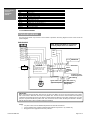
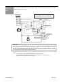
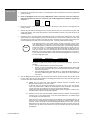
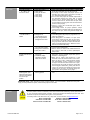
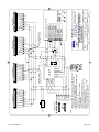
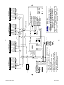
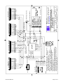
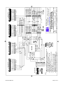
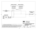
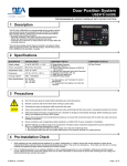
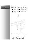
USERS GUIDE LO-21P LOCK OUT RELAY PRODUCT DESCRIPTION The microprocessed LO-21P (PN: 10LO21P) Lock Out Relay is designed to provide a lockout function for the BEA Bodyguard presence sensor, when used with the complete Parallax System. The LO-21P uses the motor and Bodyguard to determine if the swing path of the automatic door is clear and allows the door to open or close. If the swing path of the automatic door is not clear and the door is in the open position, the LO-21P will allow the Bodyguard to hold the door open as long as it detects something. If the door is closed and there is something in the Bodyguard pattern, the LO-21P will prohibit the activation device from opening the door. TECHNICAL SPECIFICATIONS DESCRIPTION Power Supply Operating Frequency Power Consumption Output Max. Voltage - Relay Contact Max. Current - Relay Contacts SPECIFICATIONS 12-24 Volts AC/ DC 4 MHz (Microprocessor) 10 mA at rest, 50 mA Max. SPST Relay 60V DC, 120V AC 2A DC, 0.5A AC COMPONENT ID Dipswitches Green LED – Activation Red LED – Safety SAFETY PRECAUTIONS • • • • • • Shut off all power going to the header before attempting any wiring procedures. Maintain a clean & safe environment when working in public areas. Constantly be aware of pedestrian traffic around the door area. Always stop pedestrian traffic through the doorway when performing tests that may result in unexpected reactions by the door. Always check placement of all wiring before powering up to insure that moving door parts will not catch any wires and cause damage to equipment. Ensure compliance with all applicable safety standards (i.e. ANSI A156.10) upon completion of installation. 75.5079.08 20061129 Page 1 of 13 ELECTRICAL INSTALLATION – OPTION 1 – STANDARD WIRING WIRE CONNECTIONS Black Motor Input Red Motor Input + Purple Bodyguard COM. Pin 3 White Bodyguard Data (-) Pin 6 Black / White Activation Sensor COM. Orange Power input / 12-24 VAC/VDC ( - ) Gray Bodyguard N.O. Pin 4 Red / White Bodyguard Data (+) Pin 7 & Activation Sensor N.O. Brown Power input / 12-24 VAC/VDC (+) Green Door Control Common Blue Door Control Activation Yellow Door Control safety LO-21P WIRING DIAGRAMS: STANDARD WIRING The wiring shown below may be used on most models of operators. See wiring diagrams at back of this manual for specific diagrams. BODYGUARD NOTE: Bodyguard MUST be programmed to a Relay Output value of 2. Default is 1. DATA + 7 DATA - 6 N.C. 5 AUTO N.O. 4 OFF COM 3 HOLD POWER 2 24 V 115 VAC TRANSFORMER red/white Blk/white white gray orange purple brown POWER 1 LO-21P NOTE: LO-21P DIPSWITCH SETTINGS: #1 THROUGH #5 - SET FOR REQUIRED LOCKOUT TIME MOTOR OPERATOR + - red black Door Control yellow SAFETY COMMON ACTIVATION STALL green blue #6 ON, #7 OFF, #8 ON Contacts to open at desired point of inhibiting 1 2 3 4 5 6 7 8 12345 Approach SuperScan 8 7 6 5 4 3 2 1 Stall SuperScan (Swing Side) EAGLE IMPORTANT: Before connecting the red and black wires from the LO-21P to the Motor, be sure to check the polarity of the voltage with a multi-meter, to determine which wire is the positive side. The red wire of the lockout module must always be connected to the positive side of the motor. When a positive reading is observed on the meter, (while the door is in hold open) the red probe indicates the positive side. Thus, the red wire of the lockout will always be attached to whatever wire the red probe was on when a positive reading was obtained. NOTES: • For pairs of doors, wire the additional SuperScans the same as shown above. • For the inhibit function, operator mounted auxiliary switches may be used – dry contacts only. • Bodyguard must be programmed to a relay value of 2. 75.5079.08 20061129 Page 2 of 13 ELECTRICAL INSTALLATION OPTION 2 – Operator Mounted Switch Wiring diagram below shows how to wire when using an operator-mounted switch to control the flow of voltage from the motor to the lockout module. Switch should be set to close a set of dry contacts when door is within 2 to 3 degrees of the full open position. BODYGUARD NOTE: Bodyguard MUST be programmed to a Relay Output value of 2. Default is 1. DATA + 7 DATA - 6 N.C. 5 AUTO N.O. 4 OFF COM 3 SINGLE POLE-DOUBLE THROW SWITCH OPERATOR AUX. SWITCH SWITCH CLOSED AT FULL OPEN POSITION HOLD POWER 2 COM NO 24 V 115 VAC TRANSFORMER red/white blk/white white gray purple orange brown POWER 1 MOTOR - red black yellow LO-21P OPERATOR + green blue MOTOR VOLTAGE SAFETY COMMON ACTIVATION STALL Door Control Contacts to open at desired point of inhibiting 1 2 3 4 5 6 7 8 12345 Approach SuperScan 8 7 6 5 4 3 2 1 Stall SuperScan (Swing Side) EAGLE IMPORTANT: Before connecting the red and black wires from the LO-21P to the Motor, be sure to check the polarity of the voltage with a multi-meter, to determine which wire is the positive side. The red wire of the lockout module must always be connected to the positive side of the motor. When a positive reading is observed on the meter, (while the door is in hold open) the red probe indicates the positive side. Thus, the red wire of the lockout will always be attached to whatever wire the red probe was on when a positive reading was obtained. NOTES: • For pairs of doors, wire the additional SuperScans the same as shown above. • For the inhibit function, operator mounted auxiliary switches may be used – dry contacts only. • Bodyguard must be programmed to a relay value of 2. 75.5079.08 20061129 Page 3 of 13 ELECTRICAL INSTALLATION Option 3 – Double Pole Double Throw Switch The wiring diagram below shows how to wire a DPDT switch to control the On-Off-Hold function, as well as data between the motor and the LO21P. NOTE: Bodyguard MUST be programmed to a Relay Output value of 2. Default is 1. BODYGUARD DATA + 7 DATA - 6 N.C. 5 AUTO N.O. 4 OFF COM 3 DOUBLE-POLE DOUBLE THROW SWITCH HOLD POWER 2 115 VAC 24 V TRANSFORMER blk/white red/white white gray purple orange brown POWER 1 + LO-21P green blue OPERATOR - red black yellow MOTOR MOTOR VOLTAGE SAFETYDoor Control COMMON ACTIVATION STALL Contacts to open at desired point of inhibiting 1 2 3 4 5 6 7 8 12345 Approach SuperScan 8 7 6 5 4 3 2 1 Stall SuperScan (Swing Side) EAGLE IMPORTANT: Before connecting the red and black wires from the LO-21P to the Motor, be sure to check the polarity of the voltage with a multi-meter, to determine which wire is the positive side. The red wire of the lockout module must always be connected to the positive side of the motor. When a positive reading is observed on the meter, (while the door is in hold open) the red probe indicates the positive side. Thus, the red wire of the lockout will always be attached to whatever wire the red probe was on when a positive reading was obtained. NOTES: • For pairs of doors, wire the additional SuperScans the same as shown above. • For the inhibit function, operator mounted auxiliary switches may be used – dry contacts only. • Bodyguard must be programmed to a relay value of 2. 75.5079.08 20061129 Page 4 of 13 SET-UP INSTRUCTIONS Upon completion of all wiring, proceed with the set-up as follows: 1. Insure that the On-Off-Hold Open switch is in the ON position, and insure that the door control is powered and operating normally. 2. Power the Bodyguard sensor and, using a BEA Remote Control, unlock the sensor and change the Output Configuration to a value of 2. If necessary, refer to the Bodyguard User’s Guide for programming instruction. + 2 3. Power the LO-21P on with 12-24 VAC/VDC, and insure all sensors or other devices in the application are properly powered 4. Observe the green LED on the Bodyguard upon powering. With the door in the closed position, the green LED should begin blinking, then expire approximately 5 seconds thereafter to indicate a successful set-up for the closed-door position. 5. Activate the door to the open position, the Bodyguard should once again begin flashing green, then expire approximately 5 seconds thereafter to indicate a successful set-up for the open-door position. If the door goes into safety swing as soon as it starts to close and you have a time delay set for the length of the closing cycle, reverse the black and red wires to the motor input for DC units. Correct any faults before proceeding. STOP If the Bodyguard learns a “door closed” position, but does not execute a set-up for the “open door position”, place the door to a hold open position. With a BEA remote control, unlock the Bodyguard, and with the door in the open position, press the Magic Wand key and then the number 2 – the Bodyguard should begin flashing green to signify a set-up. If it does not, this will be a quick indication that the improper data is being sent for the “open door” position. Check to insure that data exists on the data lines leading into the Bodyguard. In the full open position, voltage should be approximately 9 to 12 volts DC. If it is not, check the data lines (White wire on terminal 6 and Red/White wire on terminal 7) for correct voltage (see chart). CLOSED DOOR 0 Volts DC OPEN DOOR 9 to 12 Volts DC CLOSING DOOR 8 Volts DC To perform a quick test by remote control to check motor wire polarity, perform the following: • Place On-Off-Hold switch in the ON or AUTO position. • Activate the door and immediately walk into the Bodyguard detection pattern while door is open. Door should be holding open at this point. Make sure there is no Eagle activation during this time. • Unlock the Bodyguard and press Magic Wand + 2. Green LED will begin flashing – If door closes while flashing green, check for correct polarity at the red and black wire from lockout. 6. Once the Bodyguard has learned the open and closed door positions, observe the green and red LED’s on the LO-21P. Walk in and out of the field of detection for the Bodyguard while the door is open, and then again when it is closed. The LED’s indicate the following: GREEN LED: The green LED, when illuminated, indicates that there is detection at the Bodyguard while the door is in the open position. If someone steps into the Bodyguard detection zone when the door is open, the LO-21P’s Green LED will illuminate to indicate that the Bodyguard will be connected to the activation circuitry of the door, thus holding the door open as long as there is detection. Green LED will also illuminate when the activating device (Eagle) is triggered, or when On-OffHold Open switch is placed to the Hold Open position. RED LED: The red LED, when illuminated, indicates that there is detection at the Bodyguard while the door is in the closed position. It may also indicate that there is an activation signal from the Eagle or the Hold Open switch. When the door is closed, and someone steps into the detection zone of the Bodyguard, the red LED on the LO-21P will illuminate, indicating that it will ignore any activation signal it receives. Therefore, the door will remain closed until the Bodyguard detection zone is clear. Once the Bodyguard zone is clear and the door has been activated it will open and remain open for the hold time set by the motion sensor and/or door control, and will also hold open during detection at Bodyguard. 75.5079.08 20061129 Page 5 of 13 SETUP INSTRUCTION Cont. 7. 8. 9. Adjustment is necessary to configure the dipswitches to obtain the correct lock out time delay. To set the dipswitches( 1 through 5) for lock out time, perform the following: Activate the door to the open position. Time the overall door closing cycle Configure the dip switches according to the chart on Page 4 for the lockout time that is required Activate the door again to the open position Stand outside of the Bodyguard detection pattern, and while the door is closing, observe the red LED on the Bodyguard The red LED on the Bodyguard should NOT illuminate during the closing cycle. If it does, it is probably seeing the door at the very last degree or two of door closing, which would indicate that the lock out time needs to be slightly increased. Reconfigure the dipswitches to add 1 second of lock out time. When the lock out time is correct. The red LED will not illuminate during the entire closing cycle of the door. The last test is to insure that the Bodyguard detects an object as soon as the door has stopped closing. Simply allow the doors to begin closing, and step in behind the doors, into the Bodyguards field of detection. The red LED shall illuminate and remain on at the Bodyguard, and at the LO-21P, as soon as the door reaches the fully closed position, provided that an object remains in the Bodyguard’s detection field. Set the dipswitches according to the chart below to achieve the desired lockout time. The total lockout time is the sum total of the dipswitches that are in the ON position. For easy reference, use the timetables below. Default time is 7 seconds (times are approximate). Dipswitch # 1 2 3 4 5 DIPSWITCH 6, 7 and 8 OPERATION Time Delay (sec) 1 dip 1 1 sec dip 2 2 sec dip 3 4 sec dip 4 8 sec dip 5 16 sec on off off off 2 3 off on on on off off off off 4 5 off on off off on on off off dip 1 1 sec dip 2 2 sec dip 3 4 sec dip 4 8 sec dip 5 16 sec off Time Delay (sec) 17 on off off off on off off 18 19 off on on on off off off off on on off off 20 21 off on off off on on off off on on 6 off on on off off 22 off on on off on 7 8 9 on off on on off off on off off off on on off off off 23 24 25 on off on on off off on off off off on on on on on 10 11 12 off on off on on off off off on on on on off off off 26 27 28 off on off on on off off off on on on on on on on 13 14 15 on off on off on on on on on on on on off off off 29 30 31 on off on off on on on on on on on on on on on 16 off off off off on Dipswitch 6 Position ON (Default) OFF Dipswitch 7 and 8 Position 7 OFF / 8 ON (Default) 7 ON / 8 OFF 75.5079.08 20061129 Time Delay (seconds) 1 2 4 8 16 Description of Performance The LO21P expects to see voltage coming in at the red and black wire while the door is in the Open position. Typical for DC motors. The LO21P expects to see voltage coming in at the red and black wire while the door is in the Closed position. Description of Performance The LO21P CLOSES the Safety circuit (yellow wire) upon a Bodyguard Detection during the door closed position The LO21P OPENS the Safety circuit (yellow wire) upon a Bodyguard Detection during the door closed position Page 6 of 13 TROUBLESHOOTING PROBLEM Door will not open – all LED’s are OFF at the LO21P PROBABLE CAUSE 1. Faulty door control 2. Faulty LO21P 3. Faulty On-Off-Hold Open switch 4. Faulty Eagle 5. Faulty wiring Door will not open – red LED is ON at LO21P 1. Bodyguard is in detection 2. Bodyguard not programmed properly 3. Faulty wiring between Bodyguard and LO21P Door will not close 1. On-Off-Hold Open switch is in Hold Open position 2. Bodyguard is in detection 3. Faulty door control Bodyguard keeps relearning with each door position 1. Incorrect data polarity at Bodyguard 2. Insufficient voltage switching at red and black wire of LO21P As the door is closing, the Bodyguard, upon seeing the closing door, seems to reactivate the door to the open position 1. Dipswitch 6 at LO21P is in wrong position CORRECTIVE ACTION 1. Insure input power is good at LO21P – orange and brown wires. Should be 12 to 24 volts AC or DC. 2. Go directly to door control and jumper common and activation input. If door opens, proceed to next step. If not, replace/repair faulty door control. 3. Go to LO21P and jumper the red/white striped wire to the black/white striped wire. Green LED on LO21P should come on, and door should open. If not, replace LO21P. If LED comes on, but door does not open, check to insure that the blue and green wires are connected to the door control properly. 4. Check to insure that On-Off-Hold Open switch is functioning properly. 5. Check Eagle sensor for proper operation. Jumper common and N.O. terminals while wires are attached. If door does not open, check wiring between Eagle and LO21P. 1. Launch a setup on Bodyguard 2. Insure Bodyguard relay output is programmed to a value of 2. Default is 1. 3. When Bodyguard is in detection, an open circuit occurs at the purple and gray wires on the LO21P. Thus if there is any break in wiring between purple and gray and the LO21P, the lockout will react the same as if the Bodyguard were in detection. Insure there are no breaks in the wiring. 1. Place switch in On or Auto position 2. Launch a setup at Bodyguard 3. Remove wire from common and activate terminal at door control, if door does not close, replace/repair faulty control. 1. Insure that the white wire goes to terminal 6 of the Bodyguard, and the red/white striped wire goes to terminal 7 of the Bodyguard 2. When door is closed, there should be 0 volts observed on the red and black wires of the LO21P. When the door is open, voltage should be greater than approximately 9 volts. If voltage is not great enough at red and black wires when door is open, the LO21P will not be able to send the correct data to the Bodyguard. Remember, polarity must also be correct. The red wire must ALWAYS connect to the positive wire of the motor, as observed during door open position. See important note on page 2. 1. Place dipswitch 6 in opposite position and re-test the door IMPORTANT NOTE: When experiencing sensor system problems, it is recommended to disable the main power supply as to fully disable the system, until necessary repairs can be made. COMPANY CONTACT Do not leave problems unresolved. If a satisfactory solution cannot be achieved after troubleshooting a problem, please call B.E.A., Inc. If you must wait for the following workday to call B.E.A., leave the door inoperable until satisfactory repairs can be made. Never sacrifice the safe operation of the automatic door or gate for an incomplete solution. The following numbers can be called 24 hours a day, 7 days a week. For more information, visit www.beasensors.com. West: 1-888-419-2564 South-East: 1-800-407-4545 US and Canada: 1-866-249-7937 75.5079.08 20061129 Mid-West: 1-888-308-8843 North-East: 1-866-836-1863 Canada: 1-866-836-1863 Page 7 of 13 8 POWER RED NOTE: POWER 1 POWER 2 4 3 COM 5 N.O. N.C. DATA - 6 ORANGE BROWN WHITE RED/WHITE LO-21P SUPERSCAN QUICK DISCONNECT CABLE 5 N.O. BLACK / WHITE VIOLET GRAY 1 BLANK 3 INHIBIT + 1.) REMOVE FROM PIN 6 AND PLACE A WIRE NUT ON THE APPROACH SIDE SUPERSCAN'S 2 WHITE WIRES. INSTALL THE BLUE WIRE INTO PIN 6. 2.) ON SAFETY SIDE SUPERSCANS MOVE BROWN WIRE FROM PIN 5 TO PIN 4. 3.) B-SWITCH SHOULD CLOSE AT APPROX. 65-70 DEGREES. 4.) INSTALL A JUMPER BETWEEN PINS 17&18 5.) THE BODYGUARD RELAY OUTPUT FUNCTION MUST BE CHANGED TO #2. 6.) RH MOTOR SHOWN, REVERSE LO-21P RED AND BLACK WIRES FOR LH MOTOR. DK-12 BODYGUARD 4 N.C. DATA + 7 24 V TRANSFORMER 7 POWER BLACK (See Note #5) 115 VAC 2 INHIBIT GND NOT USED 1 BLANK 3 INHIBIT + 2 INHIBIT GND 8 POWER RED Common N/O N/C 7 POWER BLACK AUTO OFF HOLD OPEN EAGLE NOT USED LS HD SCALE: A SIZE: NTS DRAWN BY: GDM 80.0185 Tech Support DATE: SHEET: 6 JUNE 2003 1 OF 1 CAGE CODE: DWG NO: FILE OF: B REV: 100 Enterprise Drive Pittsburgh, PA 15275 PH: (412) 249-4100 FAX: (412) 249-4101 www.beasensors.com B.E.A., Inc. HS BESAM ETIK CONTROL TITLE: BESAM 300/400 (ETIK2) WITH LO-21P PARALLAX II SYSTEM Q-DISCONNECT ON APPROACH SIDE B-SWITCH (See Note #3) 17 STALL INPUT 18 STALL INPUT 15 STALL INPUT 16 STALL INPUT 13 ACTIVATION 12 COMMON 11 SAFETY 10 COMMON BLACK (See Note #4) 5 N.O. WHITE 8 POWER RED Motor Voltage (See Note #6) SUPERSCAN QUICK DISCONNECT CABLE NOT USED 2 INHIBIT GND RED + Wire nut 3 INHIBIT + BLACK -- NOT USED 1 BLANK (See Note #1) 7 POWER BLACK RIGHT APPROACH SIDE 6 COM BLUE (See Note #2) 4 N.C. RIGHT SAFETY SIDE 5 N.O. GREEN (See Note #2) 3 INHIBIT + LEFT SAFETY SIDE 1 BLANK (See Note #1) 2 INHIBIT GND LEFT APPROACH SIDE 6 COM BLUE 5 N.O. GREEN 8 POWER RED 7 POWER BLACK 6 COM WHITE 4 N.C. BROWN 6 COM WHITE 4 N.C. BROWN 75.5079.08 20061129 BLUE GREEN 5 N/C 4 N/O 3 COM 2 PWR 1 PWR YELLOW Page 8 of 13 3 POWER 1 POWER 2 4 COM 5 N.O. N.C. DATA - 6 5 N.O. ORANGE BROWN WHITE RED/WHITE LO-21P SUPERSCAN QUICK DISCONNECT CABLE 1 BLANK 3 INHIBIT + 7 POWER BLACK 8 POWER RED AUTO OFF HOLD OPEN VIOLET GRAY EAGLE YELLOW 1 BLANK 3 INHIBIT + (See Note #1) NOT USED LS HD A SCALE: NTS DRAWN BY: GDM 80.0186 Tech Support DATE: SHEET: 6 JUNE 2003 1 OF 1 CAGE CODE: DWG NO: FILE OF: B REV: 100 Enterprise Drive Pittsburgh, PA 15275 PH: (412) 249-4100 FAX: (412) 249-4101 www.beasensors.com B.E.A., Inc. HS BESAM ETIK CONTROL TITLE: BESAM 300/400 (ETIK2) WITH LO-21P PARALLAX II SYSTEM Q-DISCONNECT ON SAFETY SIDE SIZE: B-SWITCH (See Note #3) 17 STALL INPUT 18 STALL INPUT 15 STALL INPUT 16 STALL INPUT 13 ACTIVATION 12 COMMON 11 SAFETY 10 COMMON BLACK 8 POWER RED Motor Voltage (See Note #6) SUPERSCAN QUICK DISCONNECT CABLE (See Note #4) 5 N.O. WHITE Common N/O N/C 3 INHIBIT + NOT USED 2 INHIBIT GND RED + Wire nut 1 BLANK BLACK -- NOT USED 2 INHIBIT GND BLUE NOTE: 1.) REMOVE FROM PIN 6 AND PLACE A WIRE NUT ON THE APPROACH SIDE SUPERSCAN'S WHITE WIRE. INSTALL THE YELLOW WIRE INTO PIN 6. 2.) ON SAFETY SIDE SUPERSCAN MOVE GREEN WIRE FROM PIN 5 TO PIN 4. 3.) B-SWITCH SHOULD CLOSE AT APPROX. 65-75 DEGREES. 4.) INSTALL A JUMPER BETWEEN PINS 17&18 5.) THE BODYGUARD RELAY OUTPUT FUNCTION MUST BE CHANGED TO #2. 6.) RH MOTOR SHOWN, REVERSE LO-21P RED AND BLACK WIRES FOR LH MOTOR. DK-12 BODYGUARD 4 N.C. DATA + 7 24 V TRANSFORMER (See Note #5) 115 VAC 2 INHIBIT GND NOT USED 7 POWER BLACK RIGHT APPROACH SIDE 6 COM YELLOW (See Note #2) 5 N.O. BROWN RIGHT SAFETY SIDE 3 INHIBIT + (See Note #2) 4 N.C. LEFT SAFETY SIDE 1 BLANK (See Note #1) 2 INHIBIT GND LEFT APPROACH SIDE 8 POWER RED 7 POWER BLACK 5 N.O. BROWN 6 COM YELLOW 8 POWER RED 7 POWER BLACK 6 COM WHITE 4 N.C. GREEN 6 COM WHITE 4 N.C. GREEN 75.5079.08 20061129 GREEN 5 N/C 4 N/O 3 COM 2 PWR 1 PWR YELLOW BLACK / WHITE Page 9 of 13 8 POWER RED 4 N.C. POWER 1 POWER 2 4 3 COM 5 N.O. N.C. DATA - 6 DATA + 7 7 POWER BLACK 8 POWER RED BROWN ORANGE WHITE 4 N.C. LO-21P SUPERSCAN QUICK DISCONNECT CABLE 3 INHIBIT + 1 BLANK 6 COM WHITE 7 POWER BLACK 8 POWER RED AUTO OFF HOLD OPEN VIOLET BLACK / WHITE GRAY EAGLE VIOLET ORANGE NOT USED 100 Enterprise Drive Pittsburgh, PA 15275 PH: (412) 249-4100 FAX: (412) 249-4101 www.beasensors.com B.E.A., Inc. COMMON OPERATE SENSOR OP 12 VAC STANLEY MP 12 VAC CONTROL AUX INPUT SAFETY/STALL COMMON (See Note #5) Motor Voltage (See Note #4) SWITCH (See Note #2) 8 POWER RED SCALE: A SIZE: NTS FILE OF: DATE: 6 JUNE 2003 80.0187 Tech Support CAGE CODE: DWG NO: 1 OF 1 B GDM SHEET: REV: DRAWN BY: TITLE: STANLEY MP CONTROL WITH LO-21P PARALLAX II SYSTEM Q-DISCONNECT ON APPROACH SIDE 1 2 3 4 5 6 7 8 WHITE 5 N.O. BROWN BLACK Common N/O N/C SUPERSCAN QUICK DISCONNECT CABLE 4 N.C. BLACK -- YELLOW 3 INHIBIT + NOT USED 1 BLANK RED + RED/WHITE NOT USED 2 INHIBIT GND BLUE 1 BLANK 2 INHIBIT GND NOTE: 1.) REMOVE FROM PIN 6 AND PLACE A WIRE NUT ON THE APPROACH SIDE SUPERSCAN'S 2 WHITE WIRES. INSTALL THE BLUE WIRE INTO PIN 6. 2.) MAGIC FORCE AUX. SWITCH #4 SHOULD OPEN AT APPROX. 65-70 DEGREES. FOR MAGIC SWING REFER TO INHIBIT SWITCH BEA PT# 10 SSINHL OR 10SSINHR. 3.) THE BODYGUARD RELAY OUTPUT FUNCTION MUST BE CHANGED TO #2. 4.) SHOWN LH,RH MAGIC SWING AND RH MAGIC FORCE FOR LH MAGIC FORCE REVERSE RED AND BLACK WIRES. 5.) DOOR CONTROL SW2 SWITCH BANK SET DIPSWITCH #1 TO THE OFF (TIMER) POSITION. DK-12 BODYGUARD (See Note #3) 115 VAC 7 POWER BLACK 24 V TRANSFORMER 3 INHIBIT + NOT USED 2 INHIBIT GND (See Note #1) 7 POWER BLACK RIGHT APPROACH SIDE 4 N.C. RIGHT SAFETY SIDE 3 INHIBIT + LEFT SAFETY SIDE 1 BLANK (See Note #1) 6 COM BLUE 5 N.O. GREEN 6 COM WHITE 5 N.O. BROWN 6 COM BLUE 5 N.O. GREEN 2 INHIBIT GND LEFT APPROACH SIDE TORQUE STALL 75.5079.08 20061129 GREEN 5 N/C 4 N/O 3 COM 2 PWR 1 PWR YELLOW Page 10 of 13 8 POWER RED COM POWER 1 POWER 2 4 3 N.O. 5 DATA - 6 N.C. 2 INHIBIT GND 3 INHIBIT + NOT USED 7 POWER BLACK 8 POWER RED BROWN ORANGE WHITE RED/WHITE 4 N.C. LO-21P SUPERSCAN QUICK DISCONNECT CABLE 3 INHIBIT + 1 BLANK AUTO OFF HOLD OPEN BLACK -- RED + NOT USED 2 INHIBIT GND BLUE VIOLET GRAY BLACK / WHITE 1 BLANK NOTE: 1.) REMOVE FROM PIN 6 AND PLACE A WIRE NUT ON THE APPROACH SIDE SUPERSCAN'S WHITE WIRE. INSTALL THE YELLOW WIRE INTO PIN 6. 2.) MAGIC FORCE AUX. SWITCH #4 SHOULD OPEN AT APPROX. 65-70 DEGREES. FOR MAGIC SWING REFER TO INHIBIT SWITCH BEA PT# 10 SSINHL OR 10SSINHR. 3.) THE BODYGUARD RELAY OUTPUT FUNCTION MUST BE CHANGED TO #2. 4.) SHOWN LH,RH MAGIC SWING AND RH MAGIC FORCE FOR LH MAGIC FORCE REVERSE RED AND BLACK WIRES. 5.) DOOR CONTROL SW2 SWITCH BANK SET DIPSWITCH #1 TO THE OFF (TIMER) POSITION. DK-12 BODYGUARD 4 N.C. DATA + 7 24 V TRANSFORMER 7 POWER BLACK (See Note #3) 115 VAC 6 COM YELLOW 5 N.O. BROWN 6 COM WHITE 5 N.O. GREEN EAGLE YELLOW VIOLET ORANGE 3 INHIBIT + 1 BLANK 4 N.C. 5 N.O. GREEN 6 COM WHITE 7 POWER BLACK 8 POWER RED 8 POWER RED NOT USED SWITCH (See Note #2) 7 POWER BLACK SCALE: A SIZE: NTS FILE OF: DRAWN BY: GDM 80.0188 Tech Support DATE: SHEET: 6 JUNE 2003 1 OF 1 CAGE CODE: DWG NO: B REV: 100 Enterprise Drive Pittsburgh, PA 15275 PH: (412) 249-4100 FAX: (412) 249-4101 www.beasensors.com B.E.A., Inc. COMMON OPERATE SENSOR OP 12 VAC STANLEY MP 12 VAC CONTROL AUX INPUT SAFETY/STALL (See Note #5) COMMON Motor Voltage (See Note #4) Common N/O N/C 6 COM YELLOW TITLE: STANLEY MP CONTROL WITH LO-21P PARALLAX II SYSTEM Q-DISCONNECT ON SAFETY SIDE 1 2 3 4 5 6 7 8 WHITE BLACK SUPERSCAN QUICK DISCONNECT CABLE NOT USED 2 INHIBIT GND (See Note #1) 4 N.C. RIGHT APPROACH SIDE 5 N.O. BROWN RIGHT SAFETY SIDE 3 INHIBIT + LEFT SAFETY SIDE 1 BLANK (See Note #1) 2 INHIBIT GND LEFT APPROACH SIDE TORQUE STALL 75.5079.08 20061129 GREEN 5 N/C 4 N/O 3 COM 2 PWR 1 PWR YELLOW Page 11 of 13 7 POWER BLACK 8 POWER RED 4 N.C. POWER 1 POWER 2 4 3 COM 5 N.O. N.C. DATA - 6 DATA + 7 7 POWER BLACK 8 POWER RED + BROWN - ORANGE WHITE RED/WHITE 4 N.C. LO-21P SUPERSCAN QUICK DISCONNECT CABLE 2 INHIBIT GND 1 BLANK AUTO OFF HOLD OPEN BLACK -- RED + NOT USED 3 INHIBIT + GREEN VIOLET GRAY 1 BLANK 3 INHIBIT + NOTE: 1.) REMOVE FROM PIN 6 AND PLACE A WIRE NUT ON THE APPROACH SIDE SUPERSCAN'S 2 WHITE WIRES. INSTALL THE BLUE WIRE INTO PIN 6. 2.) THE BODYGUARD RELAY OUTPUT FUNCTION MUST BE CHANGED TO #2. 3.) DO NOT POWER ALL THE SENSORS FROM ONE CONTROL BOX . 4.) ON BOTH CONTROLS SET PMD FUNCTIONS 20=b, 19=b, 18=00, 17=00, 14=a, 13=a, 12=65 DEGREES, 11= 5 DEGREES LESS THAN F10 5.) INHIBITING THE SAFETY SIDE SUPERSCAN (F12) SHOULD OCCUR AT APPROX. 65-75 DEGREES. DK-12 BODYGUARD (See Note #2) 2 INHIBIT GND NOT USED EAGLE 2 INHIBIT GND 3 INHIBIT + 4 N.C. 5 N.O. BROWN 6 COM WHITE 7 POWER BLACK 8 POWER RED SWITCH 2 -24 VDC +24 VDC +18 VDC SWITCH 1 1 BLANK (See Note #1) -24 VDC +24 VDC +18 VDC SWITCH 2 SWITCH 1 CUP SLAVE 12 SYNC 11 0 VDC 10 SYNC 8 OFF 9 MAT 5 P DET 4 COM 3 I IMP 18 17 19 14 13 NOT USED 100 Enterprise Drive Pittsburgh, PA 15275 PH: (412) 249-4100 FAX: (412) 249-4101 www.beasensors.com B.E.A., Inc. SYNC CABLE 8 POWER RED SCALE: A SIZE: NTS FILE OF: DATE: 6 JUNE 2003 80.0193 Tech Support CAGE CODE: DWG NO: 1 OF 1 A GDM SHEET: REV: DRAWN BY: TITLE: BESAM CUP VER. 6.3,6.4 CONTROL WITH LO-21P PARALLAX II SYSTEM Q-DISCONNECT ON APPROACH SIDE CUP MASTER SYNC 12 0 VDC 11 SYNC 10 OFF 8 MAT 9 5 P DET 4 COM 3 I IMP 14 18 17 19 13 SUPERSCAN QUICK DISCONNECT CABLE NOT USED 7 POWER BLACK RIGHT APPROACH SIDE 3 INHIBIT + RIGHT SAFETY SIDE 4 N.C. LEFT SAFETY SIDE 1 BLANK (See Note #1) 2 INHIBIT GND LEFT APPROACH SIDE 6 COM BLUE 5 N.O. GREEN 6 COM WHITE 5 N.O. BROWN 6 COM BLUE 5 N.O. GREEN 75.5079.08 20061129 BLUE 5 N/C 4 N/O 3 COM 2 PWR 1 PWR YELLOW BLACK / WHITE Page 12 of 13 7 POWER BLACK 8 POWER RED 5 N.O. BROWN 4 N.C. 6 COM YELLOW 3 POWER 1 POWER 2 4 COM 5 N.O. N.C. DATA - 6 DATA + 7 7 POWER BLACK 8 POWER RED + BROWN - ORANGE WHITE RED/WHITE 4 N.C. LO-21P SUPERSCAN QUICK DISCONNECT CABLE 2 INHIBIT GND 1 BLANK AUTO OFF HOLD OPEN BLACK -- RED + NOT USED 3 INHIBIT + GREEN GRAY VIOLET 1 BLANK 2 INHIBIT GND NOTE: 1.) REMOVE FROM PIN 6 AND PLACE A WIRE NUT ON THE APPROACH SIDE SUPERSCAN'S WHITE WIRE. INSTALL THE YELLOW WIRE INTO PIN 6. 2.) THE BODYGUARD RELAY OUTPUT FUNCTION MUST BE CHANGED TO #2. 3.) DO NOT POWER ALL THE SENSORS FROM ONE CONTROL BOX . 4.) ON BOTH CONTROLS SET PMD FUNCTIONS 20=b, 19=b, 18=00, 17=00, 14=a, 13=a, 12=65 DEGREES, 11= 5 DEGREES LESS THAN F10 5.) INHIBITING THE SAFETY SIDE SUPERSCAN (F12) SHOULD OCCUR AT APPROX. 65-75 DEGREES. DK-12 BODYGUARD (See Note #2) 3 INHIBIT + NOT USED 5 N/C 4 N/O 3 COM 2 PWR 1 PWR EAGLE 3 INHIBIT + 5 N.O. GREEN 4 N.C. 6 COM WHITE 7 POWER BLACK 8 POWER RED SWITCH 2 -24 VDC +24 VDC +18 VDC SWITCH 1 1 BLANK 7 POWER BLACK 8 POWER RED -24 VDC +24 VDC +18 VDC SWITCH 2 SWITCH 1 CUP SLAVE 12 SYNC 11 0 VDC 10 SYNC 8 OFF 9 MAT 5 P DET 4 COM 3 I IMP 18 17 19 14 13 NOT USED SCALE: A SIZE: NTS FILE OF: DATE: 22 SEPT 2003 80.0194 Tech Support CAGE CODE: DWG NO: SHEET: 1 OF 1 JED DRAWN BY: B REV: 100 Enterprise Drive Pittsburgh, PA 15275 PH: (412) 249-4100 FAX: (412) 249-4101 www.beasensors.com B.E.A., Inc. SYNC CABLE 6 COM YELLOW TITLE: BESAM CUP VER. 6.3,6.4 CONTROL WITH LO-21P PARALLAX II SYSTEM Q-DISCONNECT ON SAFETY SIDE CUP MASTER SYNC 12 0 VDC 11 SYNC 10 OFF 8 9 MAT LOGIC 5 P DET 4 COM 3 I IMP 14 18 17 19 13 SUPERSCAN QUICK DISCONNECT CABLE NOT USED 2 INHIBIT GND (See Note #1) 4 N.C. RIGHT APPROACH SIDE 5 N.O. BROWN RIGHT SAFETY SIDE 2 INHIBIT GND LEFT SAFETY SIDE 3 INHIBIT + (See Note #1) 1 BLANK LEFT APPROACH SIDE 6 COM WHITE 5 N.O. GREEN 75.5079.08 20061129 BLUE YELLOW BLACK / WHITE Page 13 of 13