1
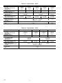
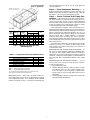
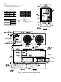
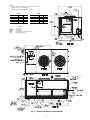
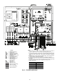
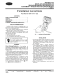
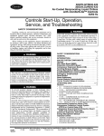
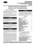
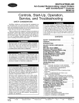
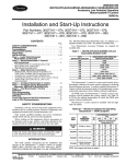
30GTN015-035
Reciprocating Liquid Chillers
with ComfortLink™ Controls
50/60 Hz
Installation Instructions
CONTENTS
Page
SAFETY CONSIDERATIONS . . . . . . . . . . . . . . . . . . . . . . 1
INSTALLATION . . . . . . . . . . . . . . . . . . . . . . . . . . . . . . . . .1-11
Step 1 — Rig and Place the Unit. . . . . . . . . . . . . . . . . . 1
• RIGGING
• PLACING UNIT
• MOUNTING UNIT
Step 2 — Check Compressor Mounting . . . . . . . . . . 3
Step 3 — Cooler Fluid and Drain Piping
Connections . . . . . . . . . . . . . . . . . . . . . . . . . . . . . . . . . . . . 3
• PREPARATION FOR YEAR-ROUND
OPERATION
• PREPARATION FOR WINTER SHUTDOWN
Step 4 — Make Electrical Connections . . . . . . . . . . . 7
• POWER SUPPLY
• POWER WIRING
Step 5 — Install Accessories . . . . . . . . . . . . . . . . . . . . 11
• ELECTRICAL
• HOT GAS BYPASS
Step 6 — Refrigerant Circuit. . . . . . . . . . . . . . . . . . . . . 11
• LEAK TESTING
• DEHYDRATION
• REFRIGERANT CHARGE
SAFETY CONSIDERATIONS
Installing, starting up, and servicing air-conditioning equipment can be hazardous due to system pressures, electrical components, and equipment location (roofs, elevated structures,
etc).
Only trained, qualified installers and service mechanics
should install, start up, and service this equipment (Fig. 1).
Untrained personnel can perform basic maintenance functions such as cleaning coils. All other operations should be performed by trained service personnel.
When working on the equipment, observe precautions in the
literature and on tags, stickers, and labels attached to the
equipment.
• Follow all safety codes.
• Wear safety glasses and work gloves.
• Keep quenching cloth and fire extinguisher nearby when
brazing.
• Use care in handling, rigging, and setting bulky
equipment.
• See Tables 1A and 1B for Physical Data.
Fig. 1 — Model 30GTN (020 Shown)
INSTALLATION
Step 1 — Rig and Place the Unit
RIGGING — Preferred method is with spreader bars from
above the unit. Use 2-in. (50 mm) OD pipe or hooks in lifting
holes. Rig with 4 cables and spreader bars. All panels must be
in place when rigging. See rigging label on unit for details concerning shipping weights, distance between lifting holes, center
of gravity, and spreader bar dimensions. See Fig. 2.
If overhead rigging is not possible, place chiller on skid or
pad for rolling or dragging. When rolling, use a minimum of
3 rollers. When dragging, pull the pad. Do not apply force to
the unit. When in final position, raise from above to lift unit off
pad.
All panels must be in place when rigging.
PLACING UNIT — There must be at least 4 ft (1.2 m) for
service and for unrestricted airflow on all sides of unit, and a
minimum of 8 ft (2.4 m) clear air space above unit. Provide
ample room for servicing cooler. For cooler removal see clearance requirements in Fig. 3-5. For multiple units, allow 8 ft
(2.4 m) separation between units for airflow and service.
If unit is to be used in an area with high solar radiation,
mounted position should be such that control box is not exposed to direct solar radiation. Exposure to direct solar radiation could affect the temperature switch controlling cooler
heaters. See Table 2.
ELECTRIC SHOCK HAZARD
Open all remote disconnects before servicing
this equipment.
Manufacturer reserves the right to discontinue, or change at any time, specifications or designs without notice and without incurring obligations.
PC 903
Catalog No. 563-068
Printed in U.S.A.
Form 30GTN-10SI
Pg 1
1-00
Replaces: New
Book 2
Tab 5c
Table 1A — Physical Data — 60 Hz
→
UNIT 30GTN
COMPRESSOR
No. ...Type
No. Cyls (ea)...Speed, Rpm (r/s)
Capacity Steps
Oil Charge*, Pt (L)
REFRIGERANT CHG, R-22
Total/Over Clear Glass, lb (kg)
CONDENSER FANS, Type
No. ...Diameter, in. (mm)
Total Airflow, Cfm (L/s)
Speed, Rpm (r/s)
CONDENSER COIL, Type
Rows...Fins/in. (Fin Spacing mm)
Total Face Area, sq ft (m2)
COOLER
Net Water Volume, gal. (L)
Maximum Design Working Pressure
psig (kPa)
WATER CONNECTIONS, in.
Inlet and Outlet
Drain
015
020
1...06DG537
6...1750 (29)
3
8 (3.8)
1...06E2250
4...1750 (29)
2
17 (8.0)
25.0 (11.3)/5.0 (2.3)
31.0 (14.1)/7.0 (3.2)
2...30 (762)
10,600 (5000)
1140 (19)
2...19 (1.34)
23.5 (2.18)
3...17 (1.49)
23.5 (2.18)
6.8 (25.7)
025
Reciprocating, Semi-Hermetic
1...06E7265
6...1750 (29)
3
21 (9.9)
030
035
1...06E7275
6...1750 (29)
3
21 (9.9)
1...06E7299
6...1750 (29)
3
19 (9.0)
40.0 (18.1)/12.0 (5.4)
47.0 (21.3)/14.0 (6.4)
Propeller Type, Direct Drive
2...30 (762)
15,700 (7400)
1140 (19)
Horizontal Plate Fin
2...19 (1.34)
3...17 (1.49)
39.2 (3.64)
39.2 (3.64)
Shell and Tube, Direct Expansion
9.9 (37.5)
Refrigerant Side — 235 (1620)
Water Side — 150 (1034)
57.0 (25.9)/8.0 (3.6)
3...30 (762)
23,700 (11 200)
1140 (19)
3...17 (1.49)
58.4 (5.43)
12.8 (48.4)
21/2 FPT
3/4 MPT
2 FPT
MPT
3/4
*See Oil Charge section for Carrier-approved oil.
Table 1B — Physical Data — 50 Hz
→
UNIT 30GTN
COMPRESSOR
No. ...Type
No. Cyls (ea)...Speed, Rpm (r/s)
Capacity Steps
Oil Charge*, Pt (L)
REFRIGERANT CHG, R-22
Total/Over Clear Glass, lb (kg)
CONDENSER FANS, Type
No. ...Diameter, in. (mm)
Total Airflow, Cfm (L/s)
Speed, Rpm (r/s)
CONDENSER COIL, Type
Rows...Fins/in. (Fin Spacing mm)
Total Face Area, sq ft (m2)
COOLER
Net Water Volume, gal. (L)
Maximum Design Working Pressure
psig (kPa)
WATER CONNECTIONS, in.
Inlet and Outlet
Drain
015
020
025
Reciprocating, Semi-Hermetic
1...06E7265
1...06E7275
6...1450 (24.2)
6...1450 (24.2)
3
3
21 (9.9)
21 (9.9)
1...06E2250
4...1450 (24.2)
2
17 (8.0)
26.0 (11.8)/6.0 (2.7)
2...30 (762)
10,600 (5000)
950 (15.8)
2...19 (1.34)
23.5 (2.18)
6.8 (25.7)
1201
2 FPT
MPT
2
1...06E7299
6...1450 (24.2)
3
19 (9.0)
35.0 (15.9)/8.0 (3.6)
42.0 (19.0)/12.0 (5.4)
49.0 (22.2)/14.0 (6.4)
Propeller Type, Direct Drive
2...30 (762)
15,700 (7400)
950 (15.8)
Horizontal, Plate Fin
3...17 (1.49)
2...19 (1.34)
3...17 (1.49)
23.5 (2.18)
39.2 (3.64)
39.2 (3.64)
Shell and Tube, Direct Expansion
9.9 (37.5)
Refrigerant Side — 235 (1620)
Water Side — 150 (1034)
3/4
*See Oil Charge section for Carrier-approved oil.
030
are field supplied. Be sure unit is level to ensure proper oil
return to compressor.
Step 2 — Check Compressor Mounting — As
shipped, compressor is held down by 4 bolts. After unit is installed, loosen each bolt using nut indicated in Fig. 6 until the
flat washer (3/8 in.) can be moved with finger pressure.
Step 3 — Cooler Fluid and Drain Piping Connections — When facing the cooler side of the unit, the re-
UNIT
30GTN
015
020
025
030
035
MAXIMUM
SHIP WT
Lb
Kg
1876 851
2031 921
2415 1095
2606 1182
3365 1526
LIFTING
HOLES
“A”
in.
mm
94.0 2388
94.0 2388
94.0 2388
94.0 2388
127.0 3225
turn water connection is on the left and the leaving water connection is on the right. See Fig. 3-5 and 7. Install a minimum
40-mesh strainer in the cooler fluid inlet line just ahead of and
as close as possible to the cooler. Provide a means of venting
air from the high point of the field-installed piping.
After field piping is complete, freeze-up protection is recommended using inhibited ethylene glycol or other suitable inhibited antifreeze solution and electric heat tapes in area where
piping is exposed to low ambient temperatures (34 F [1 C] or
below). Heat tapes should possess a rating for area ambients
and be covered with a suitable thickness of closed-cell
insulation. Route power for heating tapes from a separatelyfused disconnect. Identify disconnect as heat tape power source
with a warning that power must not be turned off except when
unit is being serviced.
The cooler drain connection is at the opposite end from the
compressor (See Fig. 3-5). Insulate the drain piping (in the
same manner as the chilled water piping) for at least one ft
(305 mm) from cooler.
PREPARATION FOR YEAR-ROUND OPERATION — If
unit is on year-round operation, add sufficient inhibited ethylene glycol or other suitable inhibited antifreeze solution to
chilled water to prevent freezing under low-ambient operating
conditions. Consult local water authority on characteristics of
area water and add a recommended inhibitor to the chilled
water.
PREPARATION FOR WINTER SHUTDOWN — Do not
shut off control power disconnect during off-season shutdown.
At end of cooling season:
1. Drain water from system.
2. Replace drain plug and put 2 gallons (8 liters) of inhibited ethylene glycol (or other suitable inhibited antifreeze) in cooler to prevent freezing of residual water.
(Remove plug on top of leaving chilled water nozzle to
add liquid.)
3. At the beginning of the next cooling season, refill cooler
and add recommended inhibitor.
CENTER OF GRAVITY
“B”
in.
48.0
47.5
51.0
51.0
66.5
mm
1219
1207
1295
1295
1689
“D”
“C”
in.
23.0
23.0
34.5
34.5
35.5
mm
583
583
876
876
901
in.
49.5
49.5
73.5
73.5
73.5
mm
1256
1256
1867
1867
1867
Fig. 2 — Rigging with Spreader Bars
(Field Supplied)
Table 2 — Temperature Limits for Standard Units
TEMPERATURE
Maximum Ambient Temperature
Minimum Ambient Temperature
Maximum Cooler EWT*
Maximum Cooler LWT
Minimum cooler LWT†
F
125
0
95
70
38
C
52
–18
35
21
3.3
LEGEND
EWT — Entering Fluid (Water) Temperature
LWT — Leaving Fluid (Water) Temperature
*For sustained operation, EWT should not exceed 85 F (29.4 C).
†Unit requires modification below this temperature.
MOUNTING UNIT — When unit is in proper location, use
of mounting holes in base rails is recommended for securing
unit to supporting structure, or for mounting unit on vibration
isolators if required. See Fig. 3-5. Fasteners for mounting unit
3
NOTES:
1. There must be minimum 8 ft (2.4 m) clear air space above unit.
2. Dimensions in [ ] are in millimeters.
3. The approximate operating weight of the unit is:
50 Hz
60 Hz
UNIT
30GTN015
30GTN015C
30GTN020
30GTN020C
UNIT
30GTN015
30GTN020
Lb
1640
1732
1821
1945
Kg
744
786
826
882
A
(1219)
4′′-0″″
(1207)
3′′-111/2″
UNIT
30GTN015
30GTN015C
30GTN020
30GTN020C
C
COMPR
MTG
NEC
VAV
—
—
—
—
—
Lb
1741
1833
1864
1988
Kg
790
831
846
902
LEGEND
Copper Coils
Compressor
Mounting
National Electrical Code (U.S.A.)
Variable-Air Volume
Fig. 3 — Dimensional Drawing, 30GTN015,020
4
NOTES:
1. There must be minimum 8 ft (2.4 m) clear air space above unit.
2. Dimensions in [ ] are in millimeters.
3. The approximate operating weight of the unit is:
60 Hz
UNIT
30GTN025
30GTN025C
30GTN030
30GTN030C
C
COMPR
MTG
NEC
VAV
—
—
—
—
—
Lb
2170
2324
2268
2474
50 Hz
Kg
984
1054
1029
1122
UNIT
30GTN025
30GTN025C
30GTN030
30GTN030C
Lb
2193
2347
2332
2538
Kg
995
1065
1058
1151
LEGEND
Copper Coils
Compressor
Mounting
National Electrical Code (U.S.A.)
Variable-Air Volume
Fig. 4 — Dimensional Drawing, 30GTN025,030
5
NOTES:
1. There must be minimum 8 ft (2.4 m) clear air space above unit.
2. Dimensions in [ ] are in millimeters.
3. The approximate operating weight of the unit is:
60 Hz
UNIT
30GTN035
30GTN035C
C
COMPR
MTG
NEC
—
—
—
—
Lb
2965
3273
Kg
1345
1485
LEGEND
Copper Coils
Compressor
Mounting
National Electrical Code (U.S.A.)
Fig. 5 — Dimensional Drawing, 30GTN035
6
NOTE: All dimensions are in inches.
Fig. 6 — Compressor Mounting
power to the Main Base Board (MBB) is off. They are
protected by a 7-amp fuse in field-supplied control power
supply disconnect.
3. The control circuit field-supplied disconnect should never
be off except when unit is being serviced or is to be down
for a prolonged period, in which case cooler should be
drained. When operation is resumed, crankcase heater
should be energized for 24 hours before start-up.
4. Power entry is at one end only.
5. Maximum field wire sizes allowed by lugs on terminal
block are:
350 kcmil for 30GTN030,035 (208/230-3-60) and
30GTN030 (230-3-50) units.
2/0 AWG for all other units.
6. Terminals for field power supply are suitable for copper,
copper-clad aluminum, or aluminum conductors. Insulation must be rated 167 F (75 C) minimum.
Field Connections
Main Power — Bring wires from the fused disconnect switch
through hole in bottom rail of unit to control box (Fig. 3-5) and
connect to terminals on terminal block TB1 (See Fig. 8).
Control Power — Bring separate source power (see Fig. 8,
note 2) into unit as shown in Fig. 3-5. This supplies power for
control circuit, compressor crankcase heater, and cooler heater.
Connect incoming wires to TB4 in unit control box (L1 to
Liquid Chiller
REFRIGERATING
MACHINE
U.N.2857
IN
WATER INLET
(RETURN WATER)
OUT
WATER OUTLET
(LEAVING WATER)
WATER
DRAIN
Fig. 7 — Water Connection Locations
Step 4 — Make Electrical Connections
POWER SUPPLY — Electrical characteristics of available
power supply must agree with unit nameplate rating. Supply
voltage must be within limits shown in Tables 3A and 3B.
IMPORTANT: Operating unit on improper supply voltage or with excessive phase imbalance constitutes abuse
and may affect Carrier warranty.
POWER WIRING — All power wiring must comply with applicable local and national codes. Install field-supplied branch
circuit fused disconnect(s) per NEC (National Electrical Code,
U.S.A.) of a type that can be locked OFF or ON. Disconnect(s)
must be within sight from and readily accessible from unit in
compliance with NEC Article 440-14.
General Wiring Notes
1. The control circuit power must be from a separate source
and must be brought through a field-supplied fused disconnect rated at 15 amps for 230-v and 30 amps for 115-v
control power. Two terminal blocks are provided for
field-wired control devices.
2. Crankcase and cooler heaters are wired in the control circuit so they are always operable as long as the control
power disconnect is on and safety device is open or the
Enable-Off-Remote contact switch is in the Off position.
Heaters are wired so that they are energized even when
and L2 to
). Neutral side must be connected to the neutral
terminal block (by C-A1) for 380-3-60 and 400-3-50 V units
only. In the auxiliary power supply a field-supplied disconnect
with 15-amp circuit protection must be provided to accommodate crankcase heater and cooler heater cable.
To comply with NEC Article 440-14, the disconnect must
be located within sight from and readily accessible from unit.
IMPORTANT: To ensure power to the heaters, make
sure auxiliary power to unit is always on (except for
servicing or prolonged shutdown).
A toggle switch (marked Emergency On-Off on the unit
label diagram and by the switch) allows the control circuit to be
manually disconnected when necessary. This switch does not
affect the crankcase heater and cooler heater cable.
7
Table 3A — Electrical Data — Standard Unit
UNIT
SIZE
30GTN
015
020
025
030
035
UNIT
Voltage
V-Hz (3 Ph)
208/230-60
460-60
575-60
380-60
380/415-50
208/230-60
460-60
575-60
380-60
380/415-50
208/230-60
460-60
575-60
380-60
380/415-50
208/230-60
460-60
575-60
380-60
380/415-50
208/230-60
460-60
575-60
380-60
Supplied*
Min
Max
187
253
414
506
518
633
418
342
342
440
187
253
414
506
518
633
418
342
342
440
187
253
414
506
518
633
418
342
342
440
187
253
414
506
518
633
418
342
342
440
187
253
414
506
518
633
418
342
MCA
82.2
38.3
31.7
43.9
49.4
97.4
49.6
42.9
51.1
60.5
124.7
60.7
52.4
64.7
68.5
145.5
68.7
54.9
73.6
87.8
203.0
91.1
81.6
111.1
MOCP
125
60
50
70
80
150
80
70
80
100
200
100
80
110
110
250
110
90
125
150
350
150
125
175
ICF
278.4
126.2
102.8
152.8
179.0
357.4
179.2
126.8
198.8
229.0
458.4
229.2
170.8
254.8
259.0
518.4
259.2
182.8
287.8
351.0
708.6
354.3
286.2
393.7
See Legend and Notes on page 9.
8
Rec Fuse
Size
100
45
40
60
60
125
60
60
60
80
150
80
70
80
90
175
90
70
90
110
250
110
100
150
V-Hz
(Single Ph)
115-60
115-60
115-60
230-60
230-50
115-60
115-60
115-60
230-60
230-50
115-60
115-60
115-60
230-60
230-50
115-60
115-60
115-60
230-60
230-50
115-60
115-60
115-60
230-60
CONTROL CIRCUIT
Supplied
MCA and
MOCP
Min
Max
104
127
30
104
127
30
104
127
30
198
254
15
198
254
15
104
127
30
104
127
30
104
127
30
198
254
15
198
254
15
104
127
30
104
127
30
104
127
30
198
254
15
198
254
15
104
127
30
104
127
30
104
127
30
198
254
15
198
254
15
104
127
30
104
127
30
104
127
30
198
254
15
Table 3B — Electrical Data — Unit with Factory-Installed Motormaster® I Control
UNIT
SIZE
30GTN
015
020
025
030
035
UNIT
Supplied*
Min
Max
187
253
414
506
518
633
418
342
342
440
187
253
414
506
518
633
418
342
342
440
187
253
414
506
518
633
418
342
342
440
187
253
414
506
518
633
418
342
342
440
187
253
414
506
518
633
418
342
Voltage
V-Hz (3 Ph)
208/230-60
460-60
575-60
380-60
380/415-50
208/230-60
460-60
575-60
380-60
380/415-50
208/230-60
460-60
575-60
380-60
380/415-50
208/230-60
460-60
575-60
380-60
380/415-50
208/230-60
460-60
575-60
380-60
MCA
82.2
38.3
30.8
43.9
51.9
97.4
49.6
42.0
51.1
63.0
124.7
60.7
51.5
64.7
71.0
145.5
68.7
54.0
73.6
90.3
203.0
91.1
80.7
111.1
MOCP
125
60
50
70
80
150
80
70
80
100
200
100
80
110
110
250
110
90
125
150
350
150
125
175
ICF
278.4
129.3
105.6
152.8
181.5
357.4
182.3
129.6
198.8
231.5
458.4
232.3
173.6
254.8
261.5
518.4
262.3
185.6
287.8
353.5
708.6
357.4
289.0
393.7
*Units are suitable for use on electrical systems where voltage supplied to unit terminals is not below or above listed minimum and
maximum limits.
NOTE: Never operate a motor where a phase imbalance in supply
voltage is greater than 2%. Use the following formula to determine
the percent voltage imbalance.
Percent Voltage Imbalance
average voltage
Example: Supply voltage is 240-3-60.
AB = 243 v
BC = 236 v
AC = 238 v
=
115-60
115-60
115-60
230-60
230-50
115-60
115-60
115-60
230-60
230-50
115-60
115-60
115-60
230-60
230-50
115-60
115-60
115-60
230-60
230-50
115-60
115-60
115-60
230-60
CONTROL CIRCUIT
Supplied
MCA and
MOCP
Min
Max
104
127
30
104
127
30
104
127
30
198
254
15
198
254
15
104
127
30
104
127
30
104
127
30
198
254
15
198
254
15
104
127
30
104
127
30
104
127
30
198
254
15
198
254
15
104
127
30
104
127
30
104
127
30
198
254
15
198
254
15
104
127
30
104
127
30
104
127
30
198
254
15
IMPORTANT: Contact your local electric utility company
immediately if the supply voltage phase imbalance is more
than 2%.
max voltage deviation from average voltage
Average voltage =
100
45
40
60
70
125
60
50
60
80
150
80
70
80
90
175
90
70
90
110
250
110
100
150
V-Hz
(Single Ph)
Determine maximum deviation from average voltage:
(AB) 243 – 239 = 4 v
(BC) 239 – 236 = 3 v
(AC) 239 – 238 = 1 v
Maximum deviation is 4 v. Determine percent voltage imbalance:
4
% Voltage Imbalance = 100 x
239
= 1.7%
This amount of phase imbalance is satisfactory as it is below the
maximum allowable 2%.
LEGEND
— Maximum Instantaneous Current Flow during starting
(the point in the starting sequence where the sum of
the LRA for the starting compressor, plus the total
RLA for all running compressors, plus the total FLA for
all running fan motors is maximum).
MCA — Minimum Circuit Amps (complies with National Electrical Code [NEC, U.S.A.], Section 430-24)
MOCP — Maximum Overcurrent Protection
ICF
= 100 x
Rec Fuse
Size
243 + 236 + 238
3
239 v
9
TB4
REMOTE
ON-OFF
C
CB
CCN
CWFS
CWP
CWPI
FC
GCS
LEN
MBB
NEC
—
—
—
—
—
—
—
—
—
—
—
TB
—
TDR
—
TRAN —
LEGEND
Compressor Contactor
Circuit Breaker
Carrier Comfort Network
Chilled Water Flow Switch
Chilled Water Pump
Chilled Water Pump Interlock
Fan Contactor
Ground Current Sensor
Local Equipment Network
Main Base Board
National Electrical Code
(U.S.A. Standard)
Terminal Block
Time Delay Relay
Transformer
Field Power Wiring
Field Control Power Wiring
Field Control Wiring
Factory-Installed Wiring
Field-Installed Device
NOTES:
1. Factory wiring is in accordance with the National Electrical Code. Any field modifications or additions must be in compliance with all applicable codes.
2. Connect separate source of control power from field supplied fused disconnect
to terminal 1 of TB4. Neutral side must be connected to terminal 2. This provides
power for the unit control circuit, cooler heater and compressor crankcase
heater.
3. All field interlock contacts must have minimum rating of 360 va pilot duty plus
capacity required for field-installed equipment.
4. For internal unit wiring reference wiring book or unit wiring label diagram.
5. For GCS accessory, remove jumper wire between terminals 5 and 8 on terminal
block TB2.
6. For part wind start accessory, remove gray jumper wire between C-A1-C1 and
C-A1A-C1. Time delay relay shown in suggested mounting position.
7. Voltage requirements:
MAIN POWER
208/230-3-60
460-3-60
575-3-60
380-3-60
380/415-3-50
CONTROL POWER
115-1-60
115-1-60
115-1-60
220-1-60
230-1-50
Fig. 8 — Field Wiring Schematic
10
Step 5 — Install Accessories
HOT GAS BYPASS — Hot gas bypass usually is not recommended because it results in application of equipment out
of its normal design application range. However, if its use is
required, the appropriate hot gas bypass package may be used.
For installation details, refer to separate instructions supplied
with the accessory package.
ELECTRICAL — A number of electrical accessories are
available to provide the following optional features (for details,
refer to the Controls, Start-Up, Operation, Service, and
Troubleshooting book):
• Energy Management Module (used for any of the following types of temperature reset, demand limit and ice
features):
— 4 to 20 mA leaving fluid temperature reset (requires
field-supplied 4 to 20 mA generator)
— 4 to 20 mA cooling set point reset (requires fieldsupplied 4 to 20 mA generator)
— Discrete inputs for 2-step demand limit (requires fieldsupplied dry contacts)
— 4 to 20 mA demand limit (requires field-supplied 4 to
20 mA generator)
— Discrete input for Ice Done switch (requires fieldsupplied dry contacts)
• Chilled fluid flow switch/interlock
• Navigator display:
Provides hand-held, mobile capability using easy to read
4-line display. Keypad function is the same as the Scrolling
Marquee module. Features magnet for ‘hands free’ service
of components.
Step 6 — Refrigerant Circuit
LEAK TESTING — Units are shipped with complete operating charge of R-22 (see Tables 1A-1B) and should be
under sufficient pressure to conduct a leak test. If there is no
pressure in the system, use standard refrigeration practices to
search for the leak. Repair the leak using good refrigeration
practices. After leaks are repaired, system must be evacuated
and dehydrated prior to recharging with refrigerant.
DEHYDRATION — Refer to Carrier Standard Service Techniques Manual, Chapter 1, Refrigerants, Sections 6 and 7 for
details. Do not use compressor to evacuate system.
REFRIGERANT CHARGE (Refer to Table 1A or 1B) —
Immediately ahead of filter drier in each circuit is a factoryinstalled liquid line service valve. Each valve has a 1/4-in.
Schrader connection for charging liquid refrigerant.
11
Copyright 2000 Carrier Corporation
Manufacturer reserves the right to discontinue, or change at any time, specifications or designs without notice and without incurring obligations.
PC 903
Catalog No. 563-068
Printed in U.S.A.
Form 30GTN-10SI
Pg 12
1201
1-00
Replaces: New
Book 2
Tab 5c