1
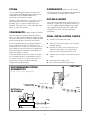
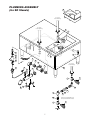
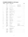
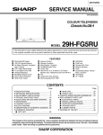
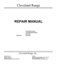
Operators Manual
Installation, Operation & Service
Direct Steam Table Top Kettles
Table-Top Direct
Steam Kettles
MODELS: KDT- 1 - T
KDT- 3 - T
KDT- 6 - T
KDT-12 - T
KDT-20 - T
SD Stands
MODELS: SD - 450
SD - 650
SD - 760
SD -1050
SD -1200
SD -1600
SD -1800
Kettles on
SD Stands
MODELS: SD -450 - K 6
SD -650 - K12
SD -760 - K12
SD -760 - K20
SD -1050 - K 6 6
SD -1200 - K 6 12
SD -1600 - K 6 20
SD -1600 - K12 12
SD -1600 - K12 20
SD -1600 - K20 20
1333 East 179th St., Cleveland, Ohio, U.S.A. 44110
Enodis
Phone: (216) 481-4900 Fax: (216) 481-3782
Visit our web site at www.clevelandrange.com
SE95008 Rev. 3
TABLE OF CONTENTS
Installation
General . . . . . . . . . . . . . . . . . . . . . . . . . . . . . . . . . . . . . . . . . . . . 1
Inspection . . . . . . . . . . . . . . . . . . . . . . . . . . . . . . . . . . . . . . . . . . . 1
Shipping Damage Instruction . . . . . . . . . . . . . . . . . . . . . . . . . . . . 1
Clearance Requirements . . . . . . . . . . . . . . . . . . . . . . . . . . . . . . . . 1
Kettles . . . . . . . . . . . . . . . . . . . . . . . . . . . . . . . . . . . . . . . . . . . . . 1
Kettles c/w SD Stand. . . . . . . . . . . . . . . . . . . . . . . . . . . . . . . . . . . 1
Steam . . . . . . . . . . . . . . . . . . . . . . . . . . . . . . . . . . . . . . . . . . . . . . 2
Condensate. . . . . . . . . . . . . . . . . . . . . . . . . . . . . . . . . . . . . . . . . . 2
Potable Water . . . . . . . . . . . . . . . . . . . . . . . . . . . . . . . . . . . . . . . . 2
Final Installation Check . . . . . . . . . . . . . . . . . . . . . . . . . . . . . . . . 2
Recommended Piping Schematics . . . . . . . . . . . . . . . . . . . . . . . . . 2
Operating Instructions
Operation . . . . . . . . . . . . . . . . . . . . . . . . . . . . . . . . . . . . . . . . . . . 3
Marine Lock . . . . . . . . . . . . . . . . . . . . . . . . . . . . . . . . . . . . . . . . . 3
Cleaning Instructions
Care & Cleaning . . . . . . . . . . . . . . . . . . . . . . . . . . . . . . . . . . . . . 4
Service Parts
Steam Control Assembly . . . . . . . . . . . . . . . . . . . . . . . . . . . . . . 5-6
Plumbing Assembly (for SD Stands). . . . . . . . . . . . . . . . . . . . . . 7-8
Faucet Assemblies . . . . . . . . . . . . . . . . . . . . . . . . . . . . . . . . . . 9-10
Maintenance
General Maintenance . . . . . . . . . . . . . . . . . . . . . . . . . . . . . . . . . 11
Pressure Relief Valve Testing Procedure . . . . . . . . . . . . . . . . . . . 11
Steam Trap . . . . . . . . . . . . . . . . . . . . . . . . . . . . . . . . . . . . . . . . . 11
Warranty . . . . . . . . . . . . . . . . . . . . . . . . . . . . . . . . . . . . . . . . . . . 11
Troubleshooting Guide . . . . . . . . . . . . . . . . . . . . . . . . . . . . . . . . 12
Steam Flow Rating of Steam Generators . . . . . . . . . . . . . . . . . . . 12
Steam Flow Rating Requirements for Kettles. . . . . . . . . . . . . . . . 12
Specification Drawings
KDT-1-T . . . . . . . . . . . . . . . . . . . . . . . . . . . . . . . . . . . . . . . . . . . 13
KDT-3-T & KDT-6-T. . . . . . . . . . . . . . . . . . . . . . . . . . . . . . . . . . 14
KDT-12-T & KDT-20-T. . . . . . . . . . . . . . . . . . . . . . . . . . . . . . . . 15
SD Stands with Kettles . . . . . . . . . . . . . . . . . . . . . . . . . . . . . . . . 16
INSTALLATION
Note: For SD Stands (with or without kettles) zero
clearance is required on the sides and back.
GENERAL
Installation of the unit must be accomplished by
qualified installation personnel working to all
applicable local and national codes. Improper
installation of product could cause injury or damage.
KETTLES
Table-top models must be positioned on a firm stand
or existing counter top and secured in place. An
optional modular cabinet base (SD Stand), with
level-adjustable legs is available .
This unit is built to comply with applicable
standards for manufacturers. Included among
those approval agencies are: UL, NSF,
ASME/Ntl.Bd., CSA, ETL, CE, and others. Many
local codes exist, and it is the responsibility of the
owner/installer to comply with these codes.
1. Make two 1" holes for
the kettle legs.
INSPECTION
A
DRILL TWO
1" HOLES
Before uncrating, visually inspect the unit for
evidence of damage during shipping. If damage
is noticed, do not unpack the unit, follow shipping
damage instructions.
KDT-1-T
KDT-3-T
KDT-6-T
KDT-12-T
KDT-20-T
8 1/8"
10"
12"
19 1/2"
23 3/4"
A
SHIPPING DAMAGE
INSTRUCTIONS
2. Remove the leg mounting
locknuts and washers from
the kettle's legs.
If shipping damage to the unit is discovered or
suspected, observe the following guidelines in
preparing a shipping damage claim.
3. Install the legs into the two
1" holes.
4. Position washers as
illustrated and secure
the kettle to its' base by
refastening the locknut
from underneath the
cabinet or countertop.
1. Write down a description of the damage or the
reason for suspecting damage as soon as it is
discovered. This will help in filling out the claim
forms later. If possible, take a polaroid picture.
2. As soon as damage is discovered or suspected,
notify the carrier that delivered the shipment.
OP
RT
TE
N
OU
C
5. Once the kettle is secure,
screw the tilt handle into
the mounting block welded
to the side of the kettle.
3. Arrange for the carrier's representative to
examine the damage.
4. Fill out all carrier claims forms and have the
examining carrier sign and date each form.
6. Install service requirements
as required.
CLEARANCE REQUIREMENTS
The first installation step is to refer to the
SPECIFICATION DRAWINGS at the back of this manual
in order to determine the exact location of the kettle.
CLEARANCE REQUIREMENTS TO COMBUSTIBLE
AND NONCOMBUSTIBLE SURFACES:
RIGHT
LEFT
KDT-1-T
KDT-3-T & KDT-6-T
4"
4"
0"
4"
0"
1"
KDT-12-T & KDT-20-T
4"
4"
1.75"
KETTLES c/w SD STAND
1. Place unit in desired location.
BACK
2. Place a carpenter's level on the kettle rim and
level the stand using the level adjustable feet.
3. Install service requirements as required.
1
STEAM
CONDENSATE
All steam plumbing to and from the kettle and
steam boiler should be thoroughly cleaned and
inspected for dirt and debris before final
connection to the kettle are made.
The stand comes factory plumbed so the condensate
is connected to the stands drain manifold.
POTABLE WATER
Generally, kettles require 1/2" i.p.s. pipe, 10-45 psi
steam pressure. If the steam supply pressure
exceeds 45 psi, a pressure reducing valve is
required. The steam inlet is at the right side of the
kettle, as seen from the front.
CONDENSATE
(Kettles c/w SD Stands)
The water faucet (optional on kettles purchased
without SD stands) with swing spout, requires 1/2
inch O.D. copper tube plumbing for hot or cold
water supplies to the faucet (SPK - cold water
connection only, DPK - hot and cold water
connection).
(Kettles without SD Stands)
Maximum pressure rating on table-top kettles is
50psi. It is highly recommended that a pressure relief
valve equal to or less than this pressure be installed
on the incoming steam line close to the kettle.
FINAL INSTALLATION CHECK
A steam condensate trap must be plumbed to a
drain, using minimum 1/2" NPT plumbing. The
condensate line is limited to a maximum rise of 10
feet in order for the steam pressure to adequately
force the condensate through the plumbing. Any
higher rise requires a pump.
2. Slowly turn the steam supply valve's knob to
the open position.
If the steam boiler to which this kettle is installed
has a condensate return (closed loop system), a
1/2" steam strainer, a 1/2" steam trap, and a 1/2"
check valve must be installed on the output
(condensate) side of the kettle.
4. Observe that the water in the kettle comes to
a boil.
1. Partially fill the kettle with water.
3. Release the safety valve, ensuring that the
steam escapes freely. Stay clear of steam
exhaust when releasing the safety valve.
5. Close the steam supply valve.
6. Drain off the water by tilting the kettle.
KETTLES
RECOMMENDED PIPING
SCHEMATICS
(all service connections shown supplied by others)
MANUAL
STEAM
VALVE
CONDENSATE RETURN
TO DRAIN OR BOILER
CONDENSATE LINE
UNION
KETTLES c/w
SD STANDS
CHECK
VALVE
STEAM
TRAP
STEAM
IN
STRAINER
STRAINER
STEAM
IN
STRAINER
UNION
BALL
VALVE
TO DRAIN (CONDENSATE RETURN PLUMBED TO 1 1/2" DRAIN MANIFOLD)
2
PRESSURE
REDUCING
VALVE
UNION
BALL
VALVE
OPERATING INSTRUCTIONS
CLEVELAND STEAM COOKING EQUIPMENT IS INTENDED FOR
COMMERCIAL USE ONLY BY PROFESSIONALLY TRAINED PERSONNEL.
OPERATION
FOR KETTLE/STEAMER COMBINATIONS:
1. Ensure that there is an adequate steam
supply to the kettle.
If the boiler in a steamer is supplying steam to a
kettle, always heat the kettle first. After the kettle
contents are heated, and the boiler's steam
pressure returns to normal, the steamer may be
used. Pressure steamer compartments should be
sequentially started, and preheated before
cooking.
2. Turn the steam control valve to
the open position by turning the
knob counter-clockwise, then allow
the kettle to preheat.
NOTE: As with cleaning food soil from any
cookware, art important part of kettle cleaning is
to prevent food from drying on. For this reason,
cleaning should be completed immediately after
cooked foods are removed. . Please read the
"Care and Cleaning" instructions for detailed kettle
washing procedures
NOTE: When cooking egg and milk products, the
kettle should NOT be preheated, as products of
this nature adhere to hot cooking surfaces. These
types of foods should be placed in the kettle
before heating is begun.
3. Fill kettle with product to desired level.
Marine Lock
4. When the product has reached
the desired temperature, regulate
the heat, as required, by turning
the steam control valve clockwise
for less steam, and therefore, a
lower temperature.
(12 & 20 gal. models only)
If your unit is equipped with
a marine lock to prevent
accidental tilting, it must be
inspected daily to insure it
moves freely and
automatically locks into place when kettle is
returned to upright position.
MARINE
LOCK
5. When cooking is complete,
close the steam control valve by
turning the knob clockwise.
Use the following procedure to tilt the kettle.
1. Securely grasp the tilt handle.
2. Push the marine lock button down to unlock
tilting mechanism.
3. Pull the handle to tilt the kettle.
4. When you return the kettle to its' original upright
position the marine lock will latch automatically.
3
CLEANING INSTRUCTIONS
CARE AND CLEANING
6. Using mild soapy water and a damp sponge,
wash the exterior of the kettle, rinse, and dry.
Your kettle must be cleaned regularly to maintain
its fast, efficient cooking performance, and to
ensure its continued safe, reliable operation.
7. Leave the cover off when the kettle is not in
use..
WARNING: Do not use chloride base detergents.
8. If your unit is equipped with a marine lock,
clean any food deposits that may have spilled
onto the mechanism.
1. Prepare a warm water and mild detergent
solution in the kettle.
2. Remove food soil inside the kettle using a
nylon brush. Do not use a metal bristle brush,
as this may permanently damage the kettle's
stainless steel surface.
NOTE: For more difficult cleaning applications
one of the following can be used: alcohol, baking
soda, vinegar, or a solution of ammonia in water.
Avoid the use of chloride cleansers, which may
damage the kettle's or stands stainless steel
surface.
3. Loosen food which is stuck to the kettle by
allowing it to soak at a low temperature
setting.
WARNING: Steel wool should never be used for
cleaning the cooking chamber of the kettle.
Particles of steel wool become embedded in the
cooking surface and rust, which may corrode the
stainless steel.
4. Tilt kettle forward to drain wash water.
5. Rinse kettle interior thoroughly, then drain the
rinse water.
4
SERVICE PARTS
STEAM CONTROL ASSEMBLY
30
5
26
5
14
1
5
23
4
4
7
8
3
22
15
1
2
5
3
4
23
16
24
25
4
6
11
7
8
9
28
23
10
1
21
12
13
7
20
19
18
17
29
8
21
20
9
5
23
27
5
4
19
7
4
18
6
23
9
6
7
8
17
5
8
9
12
13
STEAM CONTROL ASSEMBLY
ITEM NO.
PART NO.
DESCRIPTION
QTY.
1.
FA11056
Binding Head Screw, 6-32 x 1/2" lg. . . . . . . . . . . . . . . . . . . . . . . . . . . . . . . . .4
2.
KE50458
End Cap, condensate return . . . . . . . . . . . . . . . . . . . . . . . . . . . . . . . . . . . . . .1
3.
KE50455-1
Trunnion, condensate return . . . . . . . . . . . . . . . . . . . . . . . . . . . . . . . . . . . . . .1
4.
FA05002-35
"O" Ring . . . . . . . . . . . . . . . . . . . . . . . . . . . . . . . . . . . . . . . . . . . . . . . . . . . . .2
5.
FA05002-37
"O" Ring . . . . . . . . . . . . . . . . . . . . . . . . . . . . . . . . . . . . . . . . . . . . . . . . . . . . .4
6.
KE50460-1
Trunnion, steam inlet . . . . . . . . . . . . . . . . . . . . . . . . . . . . . . . . . . . . . . . . . . . .1
7.
FA11089
Binding Head Screw, 8-32 x 1/4" lg. . . . . . . . . . . . . . . . . . . . . . . . . . . . . . . . .1
8.
KE51713
Washer, steam valve . . . . . . . . . . . . . . . . . . . . . . . . . . . . . . . . . . . . . . . . . . . .1
9.
KE50459
Operating Stem . . . . . . . . . . . . . . . . . . . . . . . . . . . . . . . . . . . . . . . . . . . . . . .1
10.
KE50457
End Cap, steam inlet . . . . . . . . . . . . . . . . . . . . . . . . . . . . . . . . . . . . . . . . . . .1
11.
SE00028
Steam Control Knob Assembly (c/w Item No. 12, 13 & Knob) . . . . . . . . . . . . .1
12.
KE51888
Retaining Washer . . . . . . . . . . . . . . . . . . . . . . . . . . . . . . . . . . . . . . . . . . . . . .1
13.
FA11092
Binding Head Screw, 8-32 x 1/2" lg. . . . . . . . . . . . . . . . . . . . . . . . . . . . . . . . .1
14.
KE50151-E
Knob, threaded (after 07/94) . . . . . . . . . . . . . . . . . . . . . . . . . . . . . . . . . . . . . .1
KE50151
Knob, non threaded (prior to 06/94) . . . . . . . . . . . . . . . . . . . . . . . . . . . . . . . .1
KE50886-1
KE50886-3
Handle, KDT-1-T . . . . . . . . . . . . . . . . . . . . . . . . . . . . . . . . . . . . . . . . . . . . . . .1
Handle, KDT-3-T . . . . . . . . . . . . . . . . . . . . Requires
. . . . . . . .Knob
. . . . -. . . . . . . . . . . . . . .1
Item No.
Handle, KDT-6-T & KDT-12-T . . . . . . . . . . . . KE50151-E
. . . . . . . . . . . . . . . . . . . . . . . . .1
15.
KE50886-2
KE50886-4
Handle, KDT-20-T . . . . . . . . . . . . . . . . . . . . . . . . . . . . . . . . . . . . . . . . . . . . . .1
16.
KE50475
Plug Button . . . . . . . . . . . . . . . . . . . . . . . . . . . . . . . . . . . . . . . . . . . . . . . . . . .1
17.
KE52697
Lock Nut, 1/2" NPS . . . . . . . . . . . . . . . . . . . . . . . . . . . . . . . . . . . . . . . . . . . . .2
18.
FA32500
Lockwasher . . . . . . . . . . . . . . . . . . . . . . . . . . . . . . . . . . . . . . . . . . . . . . . . . .2
19.
FA30502
Washer, satin coat . . . . . . . . . . . . . . . . . . . . . . . . . . . . . . . . . . . . . . . . . . . . .2
20.
KE50467
Washer, Foot . . . . . . . . . . . . . . . . . . . . . . . . . . . . . . . . . . . . . . . . . . . . . . . . .2
21.
KE50465
Service Pipe, KDT-1-T & KDT-3-T . . . . . . . . . . . . . . . . . . . . . . . . . . . . . . . . . .2
KE50462
Service Pipe, KDT-6-T. . . . . . . . . . . . . . . . . . . . . . . . . . . . . . . . . . . . . . . . . . .2
KE50463
Service Pipe, KDT-12-T . . . . . . . . . . . . . . . . . . . . . . . . . . . . . . . . . . . . . . . . . .2
KE50464
Service Pipe, KDT-20-T . . . . . . . . . . . . . . . . . . . . . . . . . . . . . . . . . . . . . . . . . .2
22.
KE00203
Leg Assembly . . . . . . . . . . . . . . . . . . . . . . . . . . . . . . . . . . . . . . . . . . . . . . . .2
23.
FA05002-12
"O" Ring . . . . . . . . . . . . . . . . . . . . . . . . . . . . . . . . . . . . . . . . . . . . . . . . . . . . .1
24.
KE01115
Marine Lock Latch, KDT-12-T & KDT20-T only . . . . . . . . . . . . . . . . . . . . . . . .1
25.
KE52632
Crown Nut, KDT-12-T & KDT20-T only . . . . . . . . . . . . . . . . . . . . . . . . . . . . . . .1
26.
SE00096
Steam Outlet Assembly . . . . . . . . . . . . . . . . . . . . . . . . . . . . . . . . . . . . . . . . .1
27.
SE00011
Trunnion Assembly, steam inlet . . . . . . . . . . . . . . . . . . . . . . . . . . . . . . . . . . . .1
28.
SE00029
Operating Stem Assembly, steam inlet . . . . . . . . . . . . . . . . . . . . . . . . . . . . . .1
29.
SE00030
Steam Inlet Control Assembly . . . . . . . . . . . . . . . . . . . . . . . . . . . . . . . . . . . . .1
30.
SE00112
"O" Ring Replacement Kit . . . . . . . . . . . . . . . . . . . . . . . . . . . . . . . . . . . . . . . .1
6
PLUMBING ASSEMBLY
(for SD Stands)
29
See Steam
Control Drawing
See Steam
Control Drawing
1
2
5
STEAM
IN
3
22
20
19
4
7
21
6
CONDENSATE
RETURN
11
10
9
See Steam
Control Drawing
8
23
18
17
30
12
13
16
2
1
15
28
14
27
26
1
25
Steam In Configuration for
SD Stand with Two Kettles
24
2
1
STEAM
IN
7
PLUMBING ASSEMBLY (for SD Stands)
ITEM NO.
PART NO.
DESCRIPTION
QTY.
1.
FI00169
Tee, 1/2" NPT.
(single kettle units) . . . . . . . . . . . . .1
2.
KE51723
Pressure Relief Valve, 1/2" NPT
(single kettle units) . . . . . . . . . . . . .1
(twin kettle units) . . . . . . . . . . . . . .3
(twin kettle units) . . . . . . . . . . . . . .2
3.
FA95010
Jam Nut, #3/4-10 . . . . . . . . . . . . . . . . . . . . . . . . . . . . . . . . . . . . . . . . . . . . . .4
4.
KE51340
Leg . . . . . . . . . . . . . . . . . . . . . . . . . . . . . . . . . . . . . . . . . . . . . . . . . . . . . . . . .4
5.
SD50000
Strainer Assembly . . . . . . . . . . . . . . . . . . . . . . . . . . . . . . . . . . . . . . . . . . . . . .1
6.
SD50042
Radiator Hose, 4" lg. . . . . . . . . . . . . . . . . . . . . . . . . . . . . . . . . . . . . . . . . . . . .1
7.
FI05131
Hose Clamp . . . . . . . . . . . . . . . . . . . . . . . . . . . . . . . . . . . . . . . . . . . . . . . . . .2
8.
SD50043
Nipple, threaded one end only . . . . . . . . . . . . . . . . . . . . . . . . . . . . . . . . . . . .1
9.
KE51367
Check Valve, 1 1/4" NPT . . . . . . . . . . . . . . . . . . . . . . . . . . . . . . . . . . . . . . . . .1
10.
FI00670
Nipple . . . . . . . . . . . . . . . . . . . . . . . . . . . . . . . . . . . . . . . . . . . . . . . . . . . . . .1
11.
FI00136
90° Street Elbow, 1 1/4" NPT . . . . . . . . . . . . . . . . . . . . . . . . . . . . . . . . . . . . . .1
12.
FI00191
Cap, 1 1/2" NPT . . . . . . . . . . . . . . . . . . . . . . . . . . . . . . . . . . . . . . . . . . . . . . .1
13.
KE00648
Drain Pipe Assembly . . . . . . . . . . . . . . . . . . . . . . . . . . . . . . . . . . . . . . . . . . .1
14.
FI00044
90° Elbow, 1 1/2" NPT . . . . . . . . . . . . . . . . . . . . . . . . . . . . . . . . . . . . . . . . . . .1
15.
FI05027
Pipe Strap . . . . . . . . . . . . . . . . . . . . . . . . . . . . . . . . . . . . . . . . . . . . . . . . . . .2
16.
FI05047
Reducer . . . . . . . . . . . . . . . . . . . . . . . . . . . . . . . . . . . . . . . . . . . . . . . . . . . . .1
17.
FI05077
Compression Elbow
18.
SD50027
Steam Trap . . . . . . . . . . . . . . . . . . . . . . . . . . . . . . . . . . . . . . . . . . . . . . . . . . .1
(single kettle units) . . . . . . . . . . . . .1
19.
FI05049
Male Connector . . . . . . . . . . . . . . . . . . . . . . . . . . . . . . . . . . . . . . . . . . . . . . .1
20.
KE51249
Strainer, 1/2" NPT . . . . . . . . . . . . . . . . . . . . . . . . . . . . . . . . . . . . . . . . . . . . . .1
21.
FI00596
Nipple, 1/2" NPT . . . . . . . . . . . . . . . . . . . . . . . . . . . . . . . . . . . . . . . . . . . . . . .1
22.
FI00266
Coupling, 1/2" NPT . . . . . . . . . . . . . . . . . . . . . . . . . . . . . . . . . . . . . . . . . . . . .1
23.
FI05048
Compression Tee
24.
FI00586
Nipple . . . . . . . . . . . . . . . . . . . . . . . . . . . . . . . . . . . . . . . . . . . . . . . . . . . . . .1
(twin kettle units) . . . . . . . . . . . . . .1
25.
FI05029
Hose Fitting, 1/2" . . . . . . . . . . . . . . . . . . . . . . . . . . . . . . . . . . . . . . . . . . . . . .2
26.
KE51391
Hose Clamp . . . . . . . . . . . . . . . . . . . . . . . . . . . . . . . . . . . . . . . . . . . . . . . . . .2
27.
SD50034
Hose, 20"
(SD1050K66) . . . . . . . . . . . . . . . . .1
SD50035
Hose, 17"
(SD1200K612) . . . . . . . . . . . . . . . .1
SD50036
Hose, 27"
(SD1600K620, 1212, 12,20 & 2020) .1
28.
FI05028
90° Swivel Elbow . . . . . . . . . . . . . . . . . . . . . . . . . . . . . . . . . . . . . . . . . . . . . .1
29.
SDP
Sliding Drain Pan Assembly . . . . . . . . . . . . . . . . . . . . . . . . . . . . . . . . . . . . . .1
Front Access Panels
30.
SD50067
(SD450 series) . . . . . . . . . . . . . . . . . . . . . . . . . . . . . . . . . . . . . . . . . . . . . . . .1
SD50068
(SD650 series) . . . . . . . . . . . . . . . . . . . . . . . . . . . . . . . . . . . . . . . . . . . . . . . .1
SD50106
(SD760 series) . . . . . . . . . . . . . . . . . . . . . . . . . . . . . . . . . . . . . . . . . . . . . . . .1
SD50069
(SD1050 series) . . . . . . . . . . . . . . . . . . . . . . . . . . . . . . . . . . . . . . . . . . . . . . .1
SD50070
(SD1200 series) . . . . . . . . . . . . . . . . . . . . . . . . . . . . . . . . . . . . . . . . . . . . . . .1
SD50071
(SD1600 series) . . . . . . . . . . . . . . . . . . . . . . . . . . . . . . . . . . . . . . . . . . . . . . .1
8
FAUCET ASSEMBLIES
1
1
4
5
2
2
3
3
12
4
11
12
6
11
9
7
10
8
9
FAUCET ASSEMBLIES
ITEM NO.
PART NO.
DESCRIPTION
QTY.
1.
KE50825-8
6 gallon . . . . . . . . . . . . . . . . . . . . . . . . . . . . . . . . . . . . . . .1
KE50825-1
12 gallon . . . . . . . . . . . . . . . . . . . . . . . . . . . . . . . . . . . . . .1
KE50825-1
20 gallon . . . . . . . . . . . . . . . . . . . . . . . . . . . . . . . . . . . . . .1
2.
FA95022
Retaining Ring . . . . . . . . . . . . . . . . . . . . . . . . . . . . . . . . . . . . . . . . . . . . . . . . . .1
3.
FA05002-19
"O" Ring . . . . . . . . . . . . . . . . . . . . . . . . . . . . . . . . . . . . . . . . . . . . . . . . . . . . . . .1
4.
KE51736
Long Faucet Nut . . . . . . . . . . . . . . . . . . . . . . . . . . . . . . . . . . . . . . . . . . . . . . . .1
5.
SD50097
Flanged Nut, 3/4" NPT, Chrome Plated . . . . . . . . . . . . . . . . . . . . . . . . . . . . . . .1
6.
KE51585
Faucet Spout Fitting . . . . . . . . . . . . . . . . . . . . . . . . . . . . . . . . . . . . . . . . . . . . .1
7.
SD50098
Locknut, 3/4" NPT . . . . . . . . . . . . . . . . . . . . . . . . . . . . . . . . . . . . . . . . . . . . . . .1
8.
FI00266
Coupling, 1/2" NPT . . . . . . . . . . . . . . . . . . . . . . . . . . . . . . . . . . . . . . . . . . . . . .1
9.
KE51899
Double Pantry Control Valve . . . . . . . . . . . . . . . . . . . . . . . . . . . . . . . . . . . . . . .1
(c/w Item No. 11&12)
10.
KE51403
Double Pantry Control Valve . . . . . . . . . . . . . . . . . . . . . . . . . . . . . . . . . . . . . . .1
(c/w Item No. 11&12)
KE51401
Single Pantry Control Valve . . . . . . . . . . . . . . . . . . . . . . . . . . . . . . . . . . . . . . . .1
(c/w Item No. 12)
11.
SE50020
Hot Water Stem Assembly . . . . . . . . . . . . . . . . . . . . . . . . . . . . . . . . . . . . . . . . .1
12.
SE50021
Cold Water Stem Assembly . . . . . . . . . . . . . . . . . . . . . . . . . . . . . . . . . . . . . . . .1
10
MAINTENANCE
ALL SERVICE MUST BE PERFORMED BY A
QUALIFIED SERVICE TECHNICIAN.
This kettle requires very little preventative maintenance other than daily cleaning.
The pressure relief valve must be tested twice a year.
PRESSURE RELIEF VALVE
TESTING PROCEDURE
MARINE LOCK
Inspect lock at least twice yearly.
1. Check for excessive play or wear on pivot.
Adjust or replace as required.
WARNING
Kettle will be hot. Use gloves for protection.
2.
The pressure relief valve (optional on kettles) must
be checked at least twice a year as part of the
normal maintenance performed.
Insure lock is catching over the centre of the
stop pin and not bent to one side or the other.
Adjust or replace as required.
WARRANTY
1. Open steam valve and preheat kettle.
2. Stand to the side of the pressure relief valve
discharge tube and pull ring three or four
times to insure free movement. Hold valve
open for two seconds each time, insuring
there is rapid steam escape each time.
Our Company supports a worldwide network of
Maintenance and Repair Centers. Contact your
nearest Maintenance and Repair Centre for
replacement parts, service, or information
regarding the proper maintenance and repair of
your cooking equipment
3. If valve appears to be sticking replace
pressure relief valve. If foreign material is
discharged, replace pressure relief valve and
eliminate the source of contamination.
In order to preserve the various agency safety
certification (UL, NSF, ASME/Ntl. Bd., etc.), only
factory-supplied replacement parts should be
used. The use of other than factory supplied
replacement parts will void warranty.
STEAM TRAP
To remove line condensate that forms inside the
steam jacket, each kettle should be equipped with
a steam trap in the line of the kettle outlet to the
drain. A good steam trap at startup releases air
and wet steam into the drain line for a few
minutes, then holds the steam jacket. During
cooking, the trap periodically releases
accumulated condensate. If the kettle's cooking
performance becomes inadequate after long use,
replacement of the steam trap with a new one may
restore kettle operation to peak efficiency.
11
TROUBLESHOOTING GUIDE
This section contains information intended for use by Authorized Service Personnel only.
PROBLEM
A/ Kettle heats too slowly or does not come to a boil.
Probable Cause
Remedy
1. Inadequate steam flow.
Check for correct steam using chart below.
If kettle is connected to a steamer and powered by a
generator the units should be operated sequentially
(kettle boiling first, then start steamer).
2. Steam trap not operating properly.
The trap should open periodically to
dump condensate, then close.
If it does not open or close it should be
cleaned or replaced.
3. Food batches are not always the same.
When checking make certain that the original state (ie.
fresh or frozen) and quantity of food product is the same.
PROBLEM
B/ The trunnion housing leaks steam.
Probable Cause
Remedy
1. Trunnion "O" rings are worn.
Replace "O" rings (see STEAM CONTROL ASSEMBLY
drawing).
STEAM FLOW RATING
OF STEAM GENERATORS
Gas Input
BTU/Hour
100,000
160,000
200,000
250,000
300,000
STEAM FLOW RATING
REQUIREMENTS FOR KETTLES
Steam Output
Lbs./Hour
Boiler
H.P.
60
95
125
150
180
1.7
2.8
3.6
4.4
5.2
Capacity
Gal./Lit.
Electric
KW Input
18
24
27
36
48
60
70
90
120
150
1.7
2.0
2.6
3.5
4.4
Fast
Cooking
Medium
Cooking
Stock
Kettle
5/17
11
9
6
10/42
22
18
11
25/95
55
44
28
40/151
88
70
44
60/227
132
105
66
Electric: Above shows lbs. per hour with 10-15
psig steam at the kettle. The use of
higher steam pressures (20-25 psig) will
reduce heat-up time 5-20%.
12
SPECIFICATION DRAWINGS
KDT-1-T
CLEARANCE REQUIREMENTS TO
COMBUSTIBLE AND
NONCOMBUSTIBLE SURFACES:
Right - 4"
Left - 0
Back - 0
8.00"
203mm
9.38"
238mm
12.25"
311mm
9.88"
251mm
3.50"
89mm
12.50"
318mm
9.31"
236mm
1.56"
40mm
1/2" NPT
CONDENSATE
RETURN
8.13"
207mm
13
1/2" NPT
STEAM
INLET
KDT-3-T & KDT-6-T
CLEARANCE REQUIREMENTS TO
COMBUSTIBLE AND
NONCOMBUSTIBLE SURFACES:
Right - 4"
Left - 4"
Back - 1"
WALL
A
B
C
1.00"
25mm
H
D
WALL
STEAM
CONTROL
VALVE
E
2.25"
57mm
J
1.25"/32mm
1/2" NPT
CONDENSATE
RETURN
F
K
1/2" NPT
STEAM
INLET
G
L
NOTE: INLET AND RETURN
NOT INTERCHANGABLE
M
N
GAL.
LITRE
A
B
C
D
E
3
11
IN 14.00 10.00 15.13 12.50
mm 356
254 384
317
8.25 10.00 12.50 23.00 7.00
210
254
317
584
178
4.00 11.00 15.00 21.00
102
279
381
533
6
23
IN 17.50 13.38 15.13 15.31 11.00 12.00 14.50 24.50 6.75
mm 445
400 384
389
279
305
368
622
171
6.00 14.50 21.19 27.50
152
368
538
699
14
F
G
H
J
K
L
M
N
KDT-12-T & KDT-20-T
CLEARANCE REQUIREMENTS TO
COMBUSTIBLE AND
NONCOMBUSTIBLE SURFACES:
WALL
Right - 4"
Left - 4" Back - 1.75"
A
B
C
1.75"
45mm
H
STEAM
CONTROL
VALVE
MARINE
LOCK
D
WALL
E
2.25"
57mm
J
1.25"
32mm
F
1/2" NPT
CONDENSATE
RETURN
K
1/2" NPT
STEAM
INLET
G
L
M
NOTE: INLET AND RETURN
NOT INTERCHANGABLE
GAL.
LITRE
A
B
C
D
E
3
11
IN 20.50 16.75 23.00 22.25 13.50 19.50 22.00 29.00 6.00
mm 521
425 584
565
343
495
559
737
152
6
23
IN 25.25 21.00 27.25 18.00 11.00 23.75 26.25 33.00 6.50 10.50 13.25 36.75
mm 641
533 692
457
279
603
667
838
165
267
337
960
15
F
G
H
J
K
L
M
8.75 11.50 29.50
222
292
749
SD STANDS WITH
KETTLES
MODEL
SD -450 - K 6
CLEARANCE REQUIREMENTS TO
COMBUSTIBLE AND
NONCOMBUSTIBLE SURFACES:
SD -650 - K12
Right - 0
SD -760 - K20
Left - 0
SD -760 - K12
Back - 0
SD-1050 - K20
SD -1050 - K 6 6
SD -1200 - K 6 12
SD -1600 - K 6 20
5.00"
127mm
13.75"
349mm 16.88"
429mm
D
SD -1600 - K12 12
SD -1600 - K12 20
H C
SD -1600 - K20 20
3.25"
83mm
A
B
C
17.70
450
25.56
650
29.94
760
29.94
760
41.32
1050
41.32
1050
47.19
1200
63
1600
63
1600
63
1600
63
1600
4.00
102
4.00
102
5.22
133
3.10
79
6.50
165
4.91
125
4.10
104
9.88
251
8.25
210
6.13
156
4.00
102
10.00
254
13.75
349
15.00
381
15.00
381
34.75
883
20.66
525
19.84
504
25.63
651
31.50
800
29.38
746
31.50
800
B
C
38.75"
984mm
A
SLIDING
DRAIN PAN
SLIDING
DRAIN PAN
18.00"
457mm
MARINE
LOCK
27.75"
706mm 22.00"
610mm
6.00"
152mm
1.47"
37mm
1.47"
37mm
4.44"
113mm
1.47"
37mm
33.50"
851mm
16