1
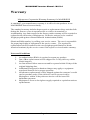
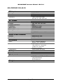
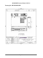
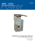
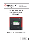
Majorsine Power Inverter
INSTALLATION & OPERATION MANUAL
MAJORSINE Inverter Manual / M101.4
Majorpower Corporation
7011 Industrial Drive
Mebane, NC 27302
Tel: 919.563.6610
Fax: 919.563.6620
Revision History
Product Manual #
Date
Release
M101.1
March 2004
Issue 1
M101.2
January 2006
Issue 2
M101.3
August 2006
Issue 3
M101.4
March 2008
Issue 4
Copyright Notice
©2008, Majorpower Corporation. All rights reserved. This document may not be copied in
whole or in part, or transferred to any other media, without the written permission of
Majorpower Corporation.
Printed in the United States of America.
Majorpower® and MAJORSINE® are registered trademarks.
Page 2
MAJORSINE Inverter Manual / M101.4
Notes:
Model Number:
Serial Number:
Installation Date:
This user’s manual contains important technical instructions
to be followed by qualified personnel responsible for the
installation, start-up and maintenance of this unit. It is
recommended that this manual be read attentively to insure
safe and reliable operation of this equipment.
Page 3
MAJORSINE Inverter Manual / M101.4
Warranty
Majorpower Corporation Warranty Summary for MAJORSINE
A standard 2 year manufacturer warranty is in effect for the products in our
MAJORSINE Power Inverter family.
The standard warranty includes depot repair or replacement of any unit that fails
during the first two years in operation due to a defect in materials or
workmanship. Any unit returned to the factory under warranty will be repaired or
replaced at the discretion of Majorpower. Defective units are to be returned
freight prepaid against a Return Material Authorization (RMA).
Obtain an RMA number, by calling your service center. The user is responsible
for prepaying freight of equipment to the service center. The repaired or
replacement unit will returned to the user freight prepaid (limited to North
America locations) by the service center if the repair is covered under warranty.
Notes and Conditions:
1.
2.
3.
4.
5.
6.
An authorization (RMA) is required to return any product.
Out of Box replacements will be shipped for 2nd day delivery within
North America.
An Out of Box Failure must occur and be reported within 30 days of the
original shipping date.
Additional testing and evaluation charges may apply to equipment
tested and found to be in proper operation.
All advance replacements will be shipped against the customer’s credit
card or purchase order. If the defective unit is not received by
Majorpower within 30 days then an invoice will be issued for
immediate payment.
Majorpower reserves the right to supply repaired or equivalent units as
replacements.
Page 4
MAJORSINE Inverter Manual / M101.4
Table of Contents
1. INTRODUCTION.............................................................. 7
1-1 GENERAL INFORMATION ...............................................................7
2. IMPORTANT SAFETY INSTRUCTIONS.................... 8
2-1 SAFETY STATEMENT ....................................................................8
2-2 ADDITIONAL SAFETY NOTES........................................................8
2-3 SYMBOLS .....................................................................................9
3. PRODUCT OVERVIEW ............................................... 10
3-1
3-2
3-3
3-4
3-5
SYSTEM FEATURES ....................................................................10
BLOCK DIAGRAM .......................................................................11
FRONT PANEL ............................................................................12
REAR PANEL ..............................................................................13
BYPASS SWITCHING AND GROUNDING .......................................14
4. INSTALLATION ............................................................ 15
4-1 DELIVERY ..................................................................................15
4-2 INSTALLATION PROCEDURES ......................................................15
4-3 INSTALLATION TOOL KIT ............................................................16
4-4 LOCKING HARDWIRE ADAPTER ..................................................16
5. OPERATION ................................................................... 17
5-1 CONNECTING THE INPUT POWER ................................................17
5-2 CONNECTING THE LOADS ...........................................................17
5-3 FRONT PANEL OPERATION (FIRMWARE VERSION 0.0 OR 3.1) ....18
5-3A FRONT PANEL OPERATION – SETTINGS @ START-UP ..............19
5-4 “DATA” BUTTON.......................................................................19
5-4 “DATA” BUTTON.......................................................................20
5-5 “STATUS” BUTTON...................................................................22
5-6 ERROR MESSAGE ........................................................................26
6. MAINTENANCE AND TROUBLESHOOTING ........ 26
6-1 MAINTENANCE ...........................................................................26
6-2 TROUBLESHOOTING ....................................................................27
6-3 ALARMS .....................................................................................28
7. COMMUNICATION...................................................... 30
7-1 DRY CONTACT COMMUNICATION TERMINAL .............................30
Page 5
MAJORSINE Inverter Manual / M101.4
7-2 SNMP EXPANSION CARD SLOT (WEB)......................................30
7-3 RS-232 COMMUNICATION PORT (GUI)......................................31
8. TECHNICAL SPECIFICATIONS................................. 32
MAJORSINE1000-24-2U ................................................................32
MAJORSINE1000-48-2U ................................................................33
MAJORSINE2000-48-2U ................................................................34
MAJORSINE1000-125-2U ..............................................................35
MAJORSINE2000-125-2U ..............................................................36
MAJORSINE1000I-48-2U...............................................................37
MAJORSINE2000I-48-2U...............................................................38
DRAWING NO. MPXXXNX02ABX..................................................39
9. OPTIONAL HARDWARE:............................................ 40
Page 6
MAJORSINE Inverter Manual / M101.4
1. INTRODUCTION
1-1 General Information
Thank you for choosing MAJORPOWER as the power products
supplier to your company. MAJORSINE Power Inverters are
designed and built for full reliability at multiple locations and
variety of applications. These intelligent, dependable inverters
provide economical AC Power for all your network needs.
Operators spanning global continents have deployed the
MAJORSINE as the choice for high availability AC power
support from a DC source.
This manual contains information and technical details for all
models in the MAJORSINE Power Inverter family. The general
operation procedures are common, however in some instances,
all or part of the information will not apply to the specific model
purchased. Refer to the specific model details page in Chapter
8: Technical Specifications.
This user’s manual contains important technical
instructions to be followed by qualified personnel
responsible for the installation, start-up and maintenance
of this unit. We recommend that this manual be read
attentively to insure safe and reliable operation of this
equipment.
Should you require any assistance, please call our Application
Engineering department at:
Tel: 888-708-6610 or (919) 563-6610
Fax: 888-708-6620 or (919) 563-6620
Email: [email protected]
Page 7
MAJORSINE Inverter Manual / M101.4
2. IMPORTANT SAFETY INSTRUCTIONS
2-1 Safety Statement
SAVE THESE INSTRUCTIONS - This manual contains important
inverter instructions that should be followed during installation and
maintenance of the MAJORSINE inverter unit.
To reduce the risk of electric shock, install the inverter in a
temperature and humidity controlled indoor environment, free of
conductive contaminants. Ambient temperature should not exceed
50oC (122oF).
Depending on use, the AC output of the inverter may require a
customer installed disconnect or fusing. For telecom use, a
GFCI has not been provided. The inverter offers standard AC
short circuit protection.
The following precautions should be respected when working
on the inverter:
Remove watches, rings, or other metal objects.
Use tools with insulated handles.
Wear rubber gloves and boots.
2-2 Additional Safety Notes
Upon receipt, examine the shipment box for damage. Notify
the carrier immediately, before opening if damage is evident.
Do not open or disassemble the inverter, warranty will be
voided.
Do not operate near water or in excessive humidity.
Keep liquid and foreign objects from entering the inverter.
Install the inverter in a well-ventilated area. Do not block front
air vents, or rear air exhausts of the unit.
Do not operate the inverter close to combustible gas or open
fire.
Do not plug appliances with surging loads, or half bridge
rectified loads, into the inverter.
Do not operate the inverter if the unit is leaking any liquid or if a
white powdery residue is found to be present.
Temperature: The inverter should be operated in an ambient
temperature range of 0°C to +50°C or output efficiency may be
affected. Air flow to the inverter must not be impeded.
Page 8
MAJORSINE Inverter Manual / M101.4
Reduced air flow: Installation of the equipment in a rack should
be such that the amount of air flow required for safe operation
of the equipment is not compromised.
Mechanical loading: Mounting of the inverter in a rack should
be level and balanced.
Wiring: Adequate input power must be supplied to the inverter
for proper use; correct wiring sizes must be respected.
Grounding: Reliable grounding of rack-mounted equipment
should be maintained.
Inverter DC power connection must be from a VDC source
within the technical specifications of the unit under installation.
2-3 Symbols
PROTECTIVE GROUNDING TERMINAL: A terminal,
which must be connected to earth ground prior to
making any other connection to the equipment.
This symbol indicates the word "phase".
Page 9
MAJORSINE Inverter Manual / M101.4
3. PRODUCT OVERVIEW
3-1 System Features
The MAJORSINE series inverter is a highly reliable DC-AC
inverter system, designed with advanced power electronics and
microprocessor technology offering the following features:
Self-Diagnosis
The MAJORSINE series inverter is equipped with a self
diagnosis microprocessor, able to identify and show all failure
messages on the LED/LCD display, with visual/audio alarm.
High Frequency Architecture
With its high frequency architecture design, the MAJORSINE
series inverter features high efficiency, light weight and
compact design.
Modular Design
MAJORSINE inverters use a modular design structure,
resulting in easy maintenance, and high MTBF.
High Efficiency
MAJORSINE series inverters offer advanced soft-switching
designs which increase operating efficiency and reduce
switching noise.
Advanced Protection Features:
Input reverse polarity-proof protection
Internal over temperature protection
Output overload protection
Output over/under voltage protection
Output short circuit protection
DC input short circuit protection: fuse and breaker
AC input short circuit protection: breaker
Input over/under voltage protection
Fan failure detection and protection
Page 10
MAJORSINE Inverter Manual / M101.4
3-2 Block Diagram
MAJORSINE Inverter Block Diagram
AC BYPASS
INPUT
FILTER
BYPASS RELAY
DC to DC Converter
DC to AC Inverter
DC
AC
DC INPUT
FILTER
DC
DC
AC
OUTPUT
OUTPUT RELAY
BREAKER
MAJORSINE inverters feature IGBT (Insulated Gate Bipolar
Transistor) technology, minimizing weight and dimension, while
enhancing output short circuit reliability and overload capacity.
Output voltage is provided in one of two ways:
1) From AC input bypass mode: (Off-Line Mode)
2) From DC to AC inverter mode: (On-Line Mode)
Either mode is front panel programmable; the selected operational
mode will predetermine the “default” output.
In the first option, Off-Line mode, AC output power will be
supplied through the AC bypass mode in its “normal” operation.
Upon AC input failure, output power will be diverted through the
DC to AC inverter mode. Once AC mains are restored, the unit will
revert from inverter mode to bypass mode.
In the second option, On-Line mode, AC output power will be
provided directly by the inverter from the VDC source. Should the
DC source or inverter fail, the system will transfer its output power
through the bypass mode. Once the DC power source is restored,
the system will revert to “inverter” mode.
Transfer time from inverter to bypass, or bypass to inverter is < 4
ms.
The Off-line/On-line mode is changed from one to the other by
pressing the ON button for less than 3 seconds when normal
output is available. The operational mode cannot be changed
during an abnormal or fault condition.
Page 11
MAJORSINE Inverter Manual / M101.4
3-3 Front Panel
MAJORPOWER.COM
Tel: 514.369.4919 Fax: 514.369.4817
http://www.majorpower.com
ON/OFF buttons:
These are the two power buttons for turning on or turning off
the inverter.
Once the inverter is on, the “ON” button works as the On-Line
<=> Off-Line mode switching button.
INVERTER ON Indicates the INVERTER has been turned on
and is working normally (output is available to support load
equipment).
OVERLOAD Means that the inverter is in overload condition,
or that there is an output short circuit.
DC ABNORMAL Means that the input DC voltage is
“abnormal” and requires verification.
FAULT Indicates that the inverter is in “fault” condition. See
Section 6-3 Alarms
**If utility by-pass is not being used, and AC input is not
present, the fault LED will remain on.
LCD Display Selection Buttons
The following data: (output voltage, output frequency, load,
input dc voltage, bypass ac voltage, bypass ac frequency, etc.)
and system status can be shown sequentially on the LCD
display by pressing these two buttons.
For more information – Refer to Section 5 Operation
Page 12
MAJORSINE Inverter Manual / M101.4
Ventilator
The ventilator on the front panel provides inverter cooling. Do
NOT obstruct this vent or the fan exhaust in the back of the
unit!
Circuit Breaker (DC Input Breaker)
The DC circuit breaker will be tripped if there is a “short circuit”
condition within the inverter. Reverse polarity protection (input)
and overload protection are integrated within the internal
circuitry and neither of these faults should trip the DC breaker.
3-4 Rear Panel
Communication Interface
MAJORSINE Inverter provides two standard and integrated
communication interfaces
a) RS-232 interface.
b) Dry Contact interface.
c) The optional SNMP/Web Adapter card is available,
please contact your Sales Distributor for information.
FAN
Inverter cooling is provided by DC fans. Forced air flow is
from front-to-back.
AC Output Receptacles
NEMA 5-15R/5-20R
4 or IEC-320 x 4
Page 13
MAJORSINE Inverter Manual / M101.4
AC Input Terminal
Terminal for bypass VAC input voltage.
AC Input Breaker
Breaker for AC input
DC Input Terminal
Terminal for VDC input voltage.
FLOATING input “+” and “-”connection.
Dry Contact Terminal
Dry contact terminal is connected to two Form C relays.
One is for “DC abnormal” and the other one is for “FAULT”.
When input DC voltage or fault occurs, the internal contact
relay will open/close.
The terminal can support 5A / 250VAC
3-5 Bypass Switching and Grounding
Operation = Off – Line Mode:
AC input supplied from local service panel,
AC I/P neutral to earth connection provided externally.
(Usually service panel)
Operation = On– Line Mode:
DC input supplied from battery/DC power system
Inverter originated AC, therefore neutral to earth
connection provided internally to chassis.
Page 14
MAJORSINE Inverter Manual / M101.4
Grounding:
Chassis to Earth Ground connection should be made per
customer installation specifications or prevailing safety
jurisdiction authority.
The inverter external safety ground plane is not switched by
operation in any mode. Typically - the chassis is mounted in a
rack or a conductor to ground plane is installed.
4. INSTALLATION
4-1 Delivery
Upon receipt of goods, check the condition of the package.
Should the package or unit be damaged, refuse receipt and/or
contact your shipper immediately to initiate your claim.
4-2 Installation Procedures
Mount unit using the brackets and screws supplied in the
hardware kit.
Please check that the input DC voltage supply meets the VDC
specification of the inverter, and verify the correct DC polarity
connections have been made to the inverter.
Turn off the DC breaker before connecting the DC voltage to
the input terminal. The DC terminal strip will accommodate
ring terminals with wire sizes recommended in chart below.
NOTE: Sparks will occur if the breaker is “on” when
connecting the input DC voltage. This is a normal condition
due to the charging current draw from the DC voltage charging
the internal capacitor of the inverter.
Connect the DC input voltage cables to the ‘+’ and ‘-’ screw
terminal only, before engaging the front panel DC breaker.
The center screw is chassis ground and should only be used if
the AC bypass service (green safety wire) is not connected.
Connect the bypass service supply. The green wire (safety)
conductor will ground the chassis.
Additional ground
conductors should not be needed to avoid creating
undesirable ground loops. Reference local standards or the
AHL for your installation requirements.
Page 15
MAJORSINE Inverter Manual / M101.4
Use the following recommended cable sizes when connecting
power to the inverter.
Model
Capacity DC Input AC Input
AC Output
MAJORSINE1000-24-2U
1 KVA
#6 AWG
#14 AWG
NEMA 5-15R
MAJORSINE1000-48-2U
1 KVA
#10 AWG #14 AWG
NEMA 5-15R
NEMA 5-20R
MAJORSINE2000-48-2U
2 KVA
#6 AWG
MAJORSINE1000i-48-2U
1 KVA
#10 AWG #14 AWG
#12 AWG
IEC-320
MAJORSINE2000i-48-2U
2 KVA
#6 AWG
IEC-320
MAJORSINE1000-125-2U
1 KVA
#12 AWG #14 AWG
NEMA 5-15R
MAJORSINE2000-125-2U
2 KVA
#12 AWG #12 AWG
NEMA 5-20R
#12 AWG
4-3 Installation Tool Kit
Contents of the tool kit include:
Poly zip bag containing twelve M4 screws and two
6-32 screws,
Two large mounting brackets (23” or 24” rack mount),
Two small mounting brackets (19” rack mount),
One protective cover for AC input,
One RS232 Cable.
4-4 Locking Hardwire Adapter
The optional adapter is a reliable locking NEMA 5-15 plug on
one end and terminal screws on the other end. The
plug-to-terminal conversion is used to secure bare wire load
circuit wiring to the output sockets of the inverter. The adapter
includes strain relief for the wires being connected to the
terminals.
Documents Also Available: Application Note # AN-001
Page 16
MAJORSINE Inverter Manual / M101.4
5. OPERATION
5-1 Connecting the Input Power
Once the DC power has been connected, engage the DC
breaker to operate the inverter.
Turn ON the AC bypass supply. Typically a circuit breaker in
the service panel.
Verify operation start-up sequence of the inverter and make
settings changes as needed for the application.
(See 5.3 or 5.3a – Front Panel Operation)
5-2 Connecting the Loads
Calculate the total power consumption (VA) of the load being
attached to the output. Make sure that the total power
consumption does not exceed the rated load of the inverter.
The load consumption can be monitored on the front screen of
the inverter using the data button.
Should the total load exceed the capacity of the inverter,
remove uncritical loads until the total load is within the capacity
of the inverter. Distribute removed loads to alternate sources
or additional inverters
Only two hardwire adapters will fit on the integrated NEMA
duplex outlets of the inverter. Loads should be distributed so
not to exceed current ratings of hardware and cable.
Page 17
MAJORSINE Inverter Manual / M101.4
5-3 Front Panel Operation
(Firmware Version 0.0 or 3.1)
1. Make sure that the complete installation has been carried
out correctly. When the breaker is turned on or the utility
input is available, the LCD of the inverter will display either
following message:
SYSTEM IS AT
OFF-LINE MODE
SYSTEM IS AT
ON-LINE MODE
2. Press the “ON” button for a minimum of one full second
(and Release within 10 seconds) to start the system
power. (if you press the ON key less than 1 second, the
CPU will not start up correctly). The inverter is in a normal
operation condition when either of the following messages
appear on the LCD screen:
INVERTER : STD BY
BYPASS : ON
INVERTER : ON
BYPASS : STD BY
Page 18
MAJORSINE Inverter Manual / M101.4
5-3a Front Panel Operation – Settings @ Start-Up
The INVERTER will automatically initiate self-checks and
start-up after 10 seconds.
Press ON Button
at least 1 full sec.
SET F=60 V= 115
I/P F=60 V= 118
Press the ON key for
entry into
programming pages.
Chang Setting?
Yes(ON) No(OFF)
O/P FREQ=60HZ
SEL.(D) Sure(ON)
O/P VOL=120V
SEL.(D) Sure(ON)
10SEC Time Out.
Press the OFF key to enter into
the INVERTER main start-up
procedure or wait 10 secs.
Start-Up Sequence
INVERTER On
SET = Last Programmed Setting for Operation
I/P = Bypass Circuit Sensor – If Present.
Page 19
MAJORSINE Inverter Manual / M101.4
5-4 “DATA” button
You can use the "DATA" button to select the following
information which is displayed on the LCD screen:
A) Output voltage:
Shows present output voltage.
OUTPUT VOLT.
***
. V ***
B) Inverter voltage:
Shows present “inverter” voltage.
INVERTER VOLT.
***
. V ***
C) Output frequency:
Shows present output frequency.
OUTPUT FREQ.
***
. Hz ***
D) Bypass AC voltage:
Shows present input bypass AC voltage.
BYPASS AC VOLT
***
. V ***
E) Bypass AC frequency:
Shows present input bypass AC frequency.
BYPASS AC FREQ
***
. Hz ***
Page 20
MAJORSINE Inverter Manual / M101.4
F) Input DC voltage:
Shows the input DC voltage.
INPUT DC VOLTAGE
***
. V ***
G) Output current:
Shows present output current.
OUTPUT CURRENT
***
. A ***
H) Output VA:
Shows present output Volt-Amp
OUTPUT VA
***
VA ***
I) Output power:
Shows present output power (Watt)
OUTPUT POWER
***
W ***
J) Temperature:
Shows the temperature inside the INVERTER
TEMPERATURE
***
. º C ***
K) Firmware Version:
Shows the CPU firmware version
FIRMWARE VERSION
*** V . ***
Page 21
MAJORSINE Inverter Manual / M101.4
5-5 “STATUS” button
You can use the "STATUS" button to select the following
information which is displayed on the LCD screen:
A) Output status:
a) When the input bypass voltage is normal and
INVERTER output voltage is from DC to AC inverter,
LCD shows
INVERTER : ON
BYPASS : STD BY
b) When the output is from input bypass AC, LCD shows
INVERTER : STD BY
BYPASS : ON
c) When the INVERTER is turned off by firmware, LCD
shows
** OUTPUT **
OUTPUT OFF
d) When the INVERTER is turned off by software, LCD
shows
** OUTPUT **
SCHEDULE OFF
B) DC to AC inverter status
a) When the INVERTER is normal, LCD shows
** INVERTER **
NORMAL
Page 22
MAJORSINE Inverter Manual / M101.4
b) When the inverter is over temperature (may be caused
by overload, high ambient temperature or fan failure),
LCD shows.
** INVERTER **
OVER TEMPERATURE
c) When the temperature inside the INVERTER is too
high, LCD shows.
** AMBIENT
**
OVER TEMPERATURE
d) When the INVERTER output is in “short circuit”
detection mode, LCD shows.
** INVERTER **
SHORT CIRCUIT
e) When the INVERTER output is overloaded beyond
rated capacity, LCD shows.
** INVERTER **
OVERLOAD
f) When the fan is in “fault”, LCD shows.
** INVERTER **
FAN FAILURE
g) When the INVERTER voltage is “too high”, LCD
shows.
** INVERTER **
OVER VOLTAGE
Page 23
MAJORSINE Inverter Manual / M101.4
h) When the INVERTER voltage is “low”, LCD shows.
** INVERTER **
UNDER VOLTAGE
C) Bypass AC status
a) When the input bypass voltage is normal, LCD shows.
** BYPASS AC **
NORMAL
b) When the input bypass voltage is normal and
INVERTER output is in “bypass mode”, LCD shows
INVERTER : STD BY
BYPASS : ON
c) When the input bypass voltage is “too low”, LCD
shows.
** BYPASS AC **
UNDER VOLTAGE
d) When the input bypass voltage is “too high”, LCD
shows.
** BYPASS AC **
OVER VOLTAGE
Page 24
MAJORSINE Inverter Manual / M101.4
e) When the input bypass is “over” normal frequency
range, LCD shows.
** BYPASS AC **
OUT OF FREQ.
f) When the output is overloaded, LCD shows.
** BYPASS AC **
OVER LOAD
D) Input DC status
a) When the input DC voltage is normal.
** INPUT DC **
NORMAL
b) When the input DC voltage is under threshold, the
LCD shows.
** INPUT DC **
LOW VOLTAGE
c) When the input DC voltage is over threshold, the LCD
shows.
** INPUT DC **
HIGH VOLTAGE
d) When the input DC voltage is under voltage, the
INVERTER will switch to bypass mode (if bypass AC
is available) and LCD shows.
DC UNDER VOLT
INVERTER OFF
Page 25
MAJORSINE Inverter Manual / M101.4
e) When the input DC voltage is over voltage, INVERTER
will switch to bypass mode (if bypass AC is available)
and LCD shows.
DC OVER VOLT
INVERTER OFF
5-6 Error message
If the following messages appear on the LCD screen,
contact Majorpower at once.
** INVERTER **
SOFTSTART FAIL
EEPROM
NOT AVAILABLE
EEPROM
checksum error
6. MAINTENANCE AND TROUBLESHOOTING
6-1 Maintenance
Make sure that the inverter vents are not blocked.
Use a vacuum cleaner to clear any dust from the fan area.
When cleaning the case or front panel, use a soft, dry cloth,
only. If the case or front panel is very dirty, use a neutral,
non-abrasive detergent. Do not use alcohol or ammonia
based solutions.
Regular service, and movement of the inverter, should be
performed by a qualified service technician.
Avoid spilling liquid on the Inverter.
Page 26
MAJORSINE Inverter Manual / M101.4
6-2 Troubleshooting
Problem
LEDs do not light up
Possible cause
Action to take
The circuit breaker is “off”
Turn on or reset the
circuit breaker.
DC cable polarity
installation
Apply correct DC
polarity.
DC input is “over” or
“under” voltage.
Apply correct DC
voltage.
Bypass AC fail
AC voltage or frequency
may be out of range.
Inverter failure.
Call for service.
Output was “short”.
Load may be abnormal
The power drawn from
the inverter exceeded
the load rating of the
inverter.
Remove unnecessary
loads or redistribute
loads to other inverters.
Incorrect transmission
rate.
Use 2400 bps baud rate
and re-test.
Wrong wire connection.
Refer to the wire
connection in chapter 7.
“FAULT” LED lights up*
“OVERLOAD” LED is ON
Communication fault.
“FAULT”LED lights, LCD Temperature inside
Check for blocked vents,
OVERTEMPERATURE the inverter is too high. or non-working fan.
*NOTE - If utility by-pass is not being used, and AC input is
not present, the fault LED will remain on.
Page 27
MAJORSINE Inverter Manual / M101.4
6-3 Alarms
Inverter Alarm Classifications
Fault Alarm Indicator includes:
Bypass AC Input High or Low Voltage
Bypass AC Input Frequency Out of Range
Fan Fail
Inverter Internal Failure
Output Load Sensing “short” condition
High Temperature
Overload Indicator includes:
The AC power drawn from the inverter exceeded the load
rating of the inverter.
See Section 8. TECHNICAL SPECIFICATIONS
DC Abnormal Indicator includes:
Input Low Voltage
Input High Voltage
DCV Input
DC Low Voltage
Trigger
DC Low Voltage
Recovery
DC High Voltage
Trigger
DC High Voltage
Recovery
24 V
48 V
125 V
21
42
101
22
44
103
29
59
149
28.5
58.5
148.5
Page 28
MAJORSINE Inverter Manual / M101.4
Bypass Utility AC Alarm Thresholds
For 100VAC system
AC Bypass Voltage
Range
AC Bypass Frequency
Range F=50Hz
AC Bypass Frequency
Range F=60Hz
AC Bypass Recovery
From Over Voltage
AC Bypass Recovery
From Under Voltage
O/P = 100Vac O/P = 110Vac O/P = 115Vac O/P = 120Vac
80Vac ~
90Vac
95Vac ~
100Vac
120Vac
~130Vac
135Vac
~140Vac
45.5Hz ~ 54.5Hz
55.5Hz ~ 64.5Hz
115Vac
125Vac
130Vac
135Vac
85Vac
95Vac
100Vac
105Vac
For 200VAC system
AC Bypass Voltage
Range
AC Bypass Frequency
Range F=50Hz
AC Bypass Frequency
Range F=60Hz
AC Bypass Recovery
From Over Voltage
AC Bypass Recovery
From Under Voltage
O/P = 208Vac O/P = 220Vac O/P = 230Vac O/P = 240Vac
188Vac
200Vac
210Vac
220Vac
~228Vac
~240Vac
~250Vac
~257Vac
45.5Hz ~ 54.5Hz
55.5Hz ~ 64.5Hz
223Vac
235Vac
245Vac
255Vac
193Vac
205Vac
215Vac
225Vac
Page 29
MAJORSINE Inverter Manual / M101.4
7. COMMUNICATION
7-1 Dry Contact Communication Terminal
The “Dry Contact” terminal is the interface for two Form C
relays. The relays are used for switching the voltage provided
by the user’s external alarm system.
One contact set is for “DC Abnormal” and the other one is for
“FAULT”. When alarms in each classification trigger, the relay
switches state. (Ref: Sec. 6-3 Alarms) Connection to the
terminal should be made to external sensor circuits with
appropriate sized wire. The terminal can support 5A / 250VAC
in either NC or NO configurations.
NC: Normally Closed
CO: Common
NO: Normally Open
7-2 SNMP Expansion Card Slot (WEB)
Remote monitoring is a prime consideration and requirement to
manage multiple network elements from a central location. SNMP
remote access as easy as; installing the plug-n-play card, configuring
your network IP address, and attaching the network interface cable.
The SNMP Kit includes:
Interface electronics card
Cover plate
RS-232 to RJ-45 custom cable
Quick installation guide
CDROM with utilities and MIB
The integrated expansion card slot is located on the rear of the
inverter behind a protective cover plate. [Ref: 3-4 Rear Panel]
Installation of the SNMP card and cover plate is easily achieved using
a standard #2 cross point screw driver. Card IP address
programming required PC interface. Instructions for installation are
included in the kit.
(kit sold separately)
Page 30
MAJORSINE Inverter Manual / M101.4
7-3 RS-232 Communication Port (GUI)
The RS-232 communication port provides the following features
using a GUI software package that is available by request from
Majorpower Corporation:
1) Communicates Fault, DC abnormal, Overload, Inverter Fail etc.
2) Monitor and display output voltage, output load, input dc voltage
and temperature.
3) Coupled with PC software application port, provides scheduled
on/off function for inverter.
Inverter monitoring data will be transmitted by local RS-232 cable.
All information is provided in GUI format and intended for local
maintenance monitoring.
HARDWARE:
BAUD RATE
2400 bps
DATA LENGTH
8 bits
STOP BIT
1 bit
PARITY
NONE
CABLING:
COMPUTER (female) - INVERTER (male)
PIN2 (RXD)
------------------
PIN2 (TXD)
PIN3 (TXD)
------------------
PIN3 (RXD)
PIN4 (PNP)
------------------
PIN4 (PNP)
PIN5 (COMMON) ---------------
PIN5 (COMMON)
PIN6 (PNP)
------------------
PIN6 (PNP)
PIN7 (PNP)
------------------
PIN7 (PNP)
Page 31
MAJORSINE Inverter Manual / M101.4
8. TECHNICAL SPECIFICATIONS
MAJORSINE1000-24-2U
DC Input
Voltage
Rated Current
Protection
Efficiency
20-30 VDC
50 Amps
Fuse and DC Breaker
>85% (full linear load),
24 VDC I/P, 120 VAC O/P
AC Output
Capacity
Voltage
Voltage Regulation
Frequency
Wave Form
THD (linear load)
THD (SPS load)
Crest Factor
Receptacles
1KVA / 800W
100, 110, 115, 120 VAC
±2%
50/60Hz ± 0.2Hz
Pure Sine Wave
3% 120 V/100%
5% 120 V/100%
3:1
(4) NEMA 5-20 R outlets
Utility Power (Bypass)
Voltage (Nominal)
Frequency
Protection
120 VAC
50/60± 5 Hz
AC Circuit Breaker
Protection
Short
Overload
Temperature
For 1 second; Switch to
Bypass, then shutdown
105-125% for 3 minutes;
126-150% for 3 seconds;
>150% for 1 second;
Switch to bypass
55 ± 5º(Inside the case)
Safety
Safety
EMI / RFI
UL / cUL
FCC Class A
Mechanical
Dimensions
Weight
17.32”W x 11.81”D x 3.46”H
(440x300x88mm)
2U Rackmount
8kg / 17.6lbs
Page 32
MAJORSINE Inverter Manual / M101.4
MAJORSINE1000-48-2U
DC Input
Voltage
Rated Current
Protection
Efficiency
40-60 VDC
25 Amps
Fuse and DC Breaker
>85% (full linear load),
48 VDC I/P, 120 VAC O/P
AC Output
Capacity
Voltage
Voltage Regulation
Frequency
Wave Form
THD (linear load)
THD (SPS load)
Crest Factor
Receptacles
1KVA / 800W
100, 110, 115, 120 VAC
±2%
50/60Hz ± 0.2Hz
Pure Sine Wave
3% 120 V/100%
5% 120 V/100%
3:1
(4) NEMA 5-15 R outlets
Utility Power (Bypass)
Voltage (Nominal)
Frequency
Protection
120 VAC
50/60± 5 Hz
AC Circuit Breaker
Protection
Short
Overload
Temperature
For 1 second; Switch to
Bypass, then shutdown
105-125% for 3 minutes
126-150% for 3 seconds;
>150% for 1 second;
Switch to bypass
55 ± 5º(Inside the case)
Safety
Safety
EMI / RFI
UL / cUL
FCC Class A
Mechanical
Dimensions
Weight
17.32”W x 11.81”D x 3.46”H
(440x300x88mm)
2U Rackmount
7kg / 15.4 lbs
Page 33
MAJORSINE Inverter Manual / M101.4
MAJORSINE2000-48-2U
DC Input
Voltage
Rated Current
Protection
Efficiency
40-60 VDC
50 Amps
Fuse and DC Breaker
>85% (full linear load),
48 VDC I/P, 120 VAC O/P
AC Output
Capacity
Voltage
Voltage Regulation
Frequency
Wave Form
THD (linear load)
THD (SPS load)
Crest Factor
Receptacles
2KVA / 1600W
100, 110, 115, 120 VAC
±2%
50/60Hz ± 0.2Hz
Pure Sine Wave
3% 120 V/100%
5% 120 V/100%
3:1
(4) NEMA 5-20 R outlets
Utility Power (Bypass)
Voltage (Nominal)
Frequency
Protection
120 VAC
50/60± 5 Hz
AC Circuit Breaker
Protection
Short
Overload
Temperature
For 1 second; Switch to
Bypass, then shutdown
105-125% for 3 minutes
126-150% for 3 seconds
>150% for 1 second;
Switch to bypass
55 ± 5º(Inside the case)
Safety
Safety
EMI / RFI
UL / cUL
FCC Class A
Mechanical
Dimensions
Weight
17.32”W x 11.81”D x 3.46”H
(440x300x88mm)
2U Rackmount
7kg / 15.4 lbs
Page 34
MAJORSINE Inverter Manual / M101.4
MAJORSINE1000-125-2U
DC Input
Voltage
Rated Current
Protection
Efficiency
100-150 VDC
10 Amps
Fuse and DC Breaker
>85% (full linear load),
125 VDC I/P, 120 VAC O/P
AC Output
Capacity
Voltage
Voltage Regulation
Frequency
Wave Form
THD (linear load)
THD (SPS load)
Crest Factor
Receptacles
1KVA / 800W
100, 110, 115, 120 VAC
±2%
50/60Hz ± 0.2Hz
Pure Sine Wave
5% 120 V/100%
3% 120 V/100%
3:1
(4) NEMA 5-15 R outlets
Utility Power (Bypass)
Voltage (Nominal)
Frequency
Protection
120 VAC
50/60± 5 Hz
AC Circuit Breaker
Protection
Short
Overload
Temperature
For 1 second; Switch to
Bypass, then shutdown
105-125% for 3 minutes
126-150% for 3 seconds;
>150% for 1 second;
Switch to bypass
55±5º (Inside the case)
Safety
Safety
EMI / RFI
UL / cUL
FCC Class A
Mechanical
Dimensions
Weight
17.32”W x 11.81”D x 3.46”H
(440x300x88mm)
2U Rackmount
7kg / 15.4 lbs
Page 35
MAJORSINE Inverter Manual / M101.4
MAJORSINE2000-125-2U
DC Input
Voltage
Rated Current
Protection
Efficiency
100-150 VDC
20 Amps
Fuse and DC Breaker
>85% (full linear load),
125 VDC I/P, 120 VAC O/P
AC Output
Capacity
Voltage
Voltage Regulation
Frequency
Wave Form
THD (linear load)
THD (SPS load)
Crest Factor
Receptacles
2KVA / 1600W
100, 110, 115, 120 VAC
±2%
50/60Hz ± 0.2Hz
Pure Sine Wave
5% 120 V/100%
3% 120 V/100%
3:1
(4) NEMA 5-20 R outlets
Utility Power (Bypass)
Voltage (Nominal)
Frequency
Protection
120 VAC
50/60± 5 Hz
AC Circuit Breaker
Protection
Short
Overload
Temperature
For 1 second; Switch to
Bypass, then shutdown
105-125% for 3 minutes
126-150% for 3 seconds
>150% for 1 second;
Switch to bypass
55±5º(Inside the case)
Safety
Safety
EMI / RFI
UL / cUL
FCC Class A
Mechanical
Dimensions
Weight
17.32”W x 11.81”D x 3.46”H
(440x300x88mm)
2U Rackmount
8kg / 17.6 lbs
Page 36
MAJORSINE Inverter Manual / M101.4
MAJORSINE1000i-48-2U
DC Input
Voltage
Rated Current
Protection
Efficiency
40-60 VDC
25 Amps
Fuse and DC Breaker
>85% (full linear load),
48 VDC I/P, 230 VAC O/P
AC Output
Capacity
Voltage
Voltage Regulation
Frequency
Wave Form
THD (linear load)
THD (SPS load)
Crest Factor
Receptacles
1KVA / 800W
208, 220, 230, 240 VAC
±2%
50/60Hz ± 0.2Hz
Pure Sine Wave
3% 120 V/100%
5% 120 V/100%
3:1
(4) IEC 320 outlets – C13
Utility Power (Bypass)
Voltage
Frequency
Protection
Nominal 230 VAC
50/60± 5 Hz
AC Circuit Breaker
Protection
Short
Overload
Temperature
For 1 second; Switch to
Bypass, then shutdown
105-125% for 3 minutes
126-150% for 3 seconds;
>150% for 1 second;
Switch to bypass
55±5º(Inside the case)
Safety
Safety
EMI / RFI
CE Approved
FCC Class A
Mechanical
Dimensions
Weight
17.32”W x 11.81”D x 3.46”H
(440x300x88mm)
2U Rackmount
7kg / 15.4 lbs
Page 37
MAJORSINE Inverter Manual / M101.4
MAJORSINE2000i-48-2U
DC Input
Voltage
Rated Current
Protection
Efficiency
40-60 VDC
50 Amps
Fuse and DC Breaker
>85% (full linear load),
48 VDC I/P, 230 VAC O/P
AC Output
Capacity
Voltage
Voltage Regulation
Frequency
Wave Form
THD (linear load)
THD (SPS load)
Crest Factor
Receptacles
2KVA / 1600W
208, 220, 230, 240 VAC
±2%
50/60Hz ± 0.2Hz
Pure Sine Wave
3% 120 V/100%
5% 120 V/100%
3:1
(4) IEC 320 outlets – C13
Utility Power (Bypass)
Voltage
Frequency
Protection
Nominal 230 VAC
50/60± 5 Hz
AC Circuit Breaker
Protection
Short
Overload
Temperature
For 1 second; Switch to
Bypass, then shutdown
105-125% for 3 minutes
126-150% for 3 seconds
>150% for 1 second;
Switch to bypass
55±5º(Inside the case)
Safety
Safety
EMI / RFI
CE Approved
FCC Class A
Mechanical
Dimensions
Weight
17.32”W x 11.81”D x 3.46”H
(440x300x88mm)
2U Rackmount
8kg / 17.6 lbs
Page 38
MAJORSINE Inverter Manual / M101.4
Drawing No. MPXXXNX02ABX
Page 39
MAJORSINE Inverter Manual / M101.4
9. Optional Hardware:
SNMP Remote Communication Card:
Remote monitoring is a prime consideration and requirement to
manage multiple network elements from a central location.
Remote access is established by simply installing the
plug-n-play card, configuring your network IP address, and
attaching the network interface cable.
Locking - Hardwire Adapter:
Reliable locking NEMA 5-15 plug to secure load circuits to the
output sockets of the inverter. Heavy-duty design locks the plug
in place to prevent disconnecting critical loads.
[Note: Only two hardwire adapters will fit on the integrated NEMA duplex
outlets of the inverter. Loads should be distributed so not to exceed current
ratings of hardware and cable.]
Page 40