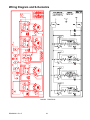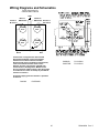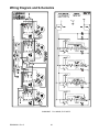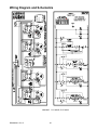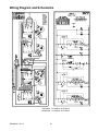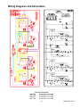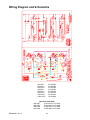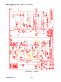
1
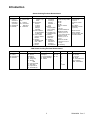
Models and manufacturing numbers in this manual are listed on page 4. Service Electric Cooktops This manual replaces RS2420002 Rev. 4. Service Manual for Amana This manual is to be used by qualified appliance technicians only. Amana does not assume any responsibility for property damage or personal injury for improper service procedures done by an unqualified person. RS2420002 Revision 5 July 1999 Important Information Pride and workmanship go into every product to provide our customers with quality products. It is possible however, that during its lifetime a product may require service. Products should be serviced only by a qualified service technician who is familiar with the safety procedures required in the repair and who is equipped with the proper tools, parts, testing instruments and the appropriate service manual. REVIEW ALL SERVICE INFORMATION IN THE APPROPRIATE SERVICE MANUAL BEFORE BEGINNING REPAIRS. IMPORTANT NOTICES ! WARNING If repairs are attempted by unqualified persons, dangerous conditions (such as exposure to electrical shock) may result. This may cause serious injury or death. ! CAUTION Amana will not be responsible for any injury or property damage arising from improper service or service procedures. If you perform service on your own product, you assume responsibility for any personal injury or property damage which may result. To locate an authorized servicer, consult your telephone book or the dealer from whom you purchased this product. For further assistance, contact: 1 (800) 628-5782 first, if no answer call number listed below. CONSUMER AFFAIRS DEPT. AMANA APPLIANCES AMANA, IOWA 52204 OR 1 (800) 843-0304 CALL If outside the United States contact: AMANA ATTN: CONSUMER AFFAIRS DEPT. 2800 220th TRAIL AMANA, IOWA 52204, USA Telephone: (319) 622-5511 Facsimile: (319) 622-2180 TELEX: 4330076 AMANA CABLE: “AMANA”, AMANA, IOWA, USA RECOGNIZE SAFETY SYMBOLS, WORDS AND LABELS ! DANGER DANGER - ! WARNING WARNING - Hazards or unsafe practices which COULD result in severe personal injury or death. ! CAUTION CAUTION - RS2420002 Rev. 5 Immediate hazards which WILL result in severe personal injury or death. Hazards or unsafe practices which COULD result in minor personal injury or product or property damage. 2 Table of Contents Important Information Introduction General Information............................................ 4 Model Identification and Ordering Replacement Parts.......................................... 4 Amana Cooking Products Nomenclature............ 5 1996 Amana Cooking Products Nomenclature... 5 Important Information General............................................................... 6 Surface Cooking................................................. 6 Safety Procedures.............................................. 6 Installation Installation Options...............................................7 Cabinet Cutout................................................ 7 Minimum Clearances...................................... 7 Inlay Countertop Installation............................... 8 Models AK2T30/36E1/W1 and AK2H30/36E2/W2.......................................... 8 Inlay Kit Installation Instructions...................... 8 Ceramic Tile Countertop................................. 8 Laminate Countertop....................................... 8 Solid Surface Countertop................................ 8 Connecting Electrical Supply.............................. 9 Placing Cooktop in Cutout.................................. 9 Checking for Proper Operation........................... 9 Removing and Replacing Cooktop..................... 9 Operating Instructions Using the Cooktop............................................ 10 Cooking Utensils............................................... 10 Using a Wok..................................................... 10 AKE Unit Description........................................ 10 AKH, AK2H, CAK2H, and CAKH Unit Description................................................ 11 AKT, AK2T, and CAK2T Unit Description......... 11 Operating Surface Elements−All Models.......... 11 Operating Single Radiant Element................ 11 Operating Dual Radiant Element................... 11 Operating Halogen Heater............................. 12 Operating 10−Position Halogen Element....... 12 Surface Element Hot Indicator Lights............ 12 Changing Fuses−Canadian Models Before Date Code 2/96.................................. 12 Cleaning............................................................ 12 Troubleshooting Procedures Cleaning Glass/Ceramic Cooktop..................... 13 Power Supply.................................................... 14 Internal Wiring................................................... 14 Surface Control................................................. 14 Power Connection......................................... 14 Infinite Switch Surface Controls........................ 14 Power Disconnected...................................... 14 Functional Test.............................................. 14 Multi−Position Switch........................................ 15 Continuity Test............................................... 15 CAKH and AKH Units........................................ 16 Halogen Element Continuity Test................... 16 Performance Test........................................... 16 Halogen Element and Quick Star Elements...... 16 High Temperature Limit/Hot Light Switch....... 16 Quick Star Elements−Power Disconnected....... 16 Small Element Continuity Test....................... 16 Large Element Continuity Test....................... 16 Quick Star Element−Power Connected............. 16 Performance Test........................................... 16 AKE Units−Solid Disk Elements........................ 16 Continuity Test−Power Disconnected............. 16 Performance Test−Power Connected............. 16 Indicator Lights and Diode Assembly− Some Models..................................................... 17 Power Connected........................................... 17 Chart.................................................................. 18 Disassembly Procedures AKE Models....................................................... 20 Burner Replacement...................................... 20 Element TCO Replacement........................... 20 Indicator Light Replacement........................... 20 AKH Models....................................................... 20 Burner Replacement...................................... 20 Surface Control Replacement........................ 20 HI−Temp Limiter/Hot Light Switch.................. 20 Wiring Diagrams and Schematics All Models.......................................................... 21 3 RS2420002 Rev. 5 Introduction General Information This manual provides complete instructions and suggestions for handling, installing and servicing Amana gas cooktops. Directions, information, and warnings in this manual are developed from experience with, and careful testing of the product. If the unit is installed according to the manual, it will operate properly and will require minimal servicing. A unit in proper operating order ensures the consumer all the benefits provided by clean, modern electric cooking. This manual contains all the information needed by authorized Amana service technicians to install and service Amana, Caloric, Modern Maid gas cooktops. However, some parts need further explanation. Amana maintains a toll-free technical support line to answer questions from authorized service technicians. The number is 1800-AMANA99. Model Identification and Ordering Replacement Parts Unit’s model and manufacturing numbers are recorded on its rating label. Rating label is located on the bottom of sealed burner units. On open burner units, rating label is located under maintop. Lift cooktop from front edge to see rating label on top of burner box. Before ordering parts, write down the correct model and manufacturing numbers from rating label. This avoids incorrect shipments and delays. Please refer to parts catalog when ordering replacement parts. Models and manufacturing numbers covered in this manual. AK2H30 AK2H30 AK2H30*2 AK2H30*3 AK2H30*4 AK2H30W3 AK2H30W3 AK2H30E4 AK2H30E4 AK2H30E4 AK2H300 AK2H300 AK2H30HR AK2H30HR AK2H35 AK2H35 AK2H35HR AK2H35HR AK2H36*2 AK2H36*3 AK2H36*4 AK2H36W3 AK2H36W3 AK2H36E4 AK2H36E4 AK2T30 AK2T30 AK2T30 AK2T30 AK2T30* AK2T30*2 AK2T30*4 AK2T30W2 AK2T30W2 AK2T30W2 AK2T30E4 AK2T30E4 AK2T30E4 AK2T30*4 AK2T35 AK2T35 AK2T35 AK2T35 AK2T36*1 AK2T36*2 AK2T36*4 RS2420002 Rev. 5 AK2T36W2 AK2T36W2 AK2T36W2 AK2T36W2 AK2T36E4 AK2T36E4 AK2T36E4 AKE30 AKE30 AKE30E2 AKE30E2 AKE30W2 AKE30W2 AKE35 AKE35 AKE35E2 AKE35E2 AKE35W2 AKE35W2 AKH30 AKH30HR AKH35 AKH35HR AKT3000 AKT3000* AKT3000* CAK2H30 CAK2H30*1 CAK2H30*1 CAK2H30*2 CAK2H30W1 CAK2H30E2 CAK2H30HR CAK2T30 CAK2T30*1 CAK2T30*1 CAK2T30*2 CAK2T30W1 CAK2T30E2 CAKE30 CAKE30E2 CAKE30E2 CAKE30W2 CAKE30W2 CAKH30 CAKH30HR P1131546N P8597804S P1131559N P1131565N P1131578N P1131591N W P1143705N W P1131591N E P1143701N E P1143719N E P1156301S P1156302S P1119901S P1119911S P1131547N P8597805S P1119902S P1119912S P1131557N P1131566N P1131579N P1131592N W P1143720N W P1131592N E P1143702N E P1165101S P1165103S P1172101S P1172102S P1131560N P1131563N P1131576N P1131593N W P1143703N W P1143721N W P1131593N E P1143703N E P1143721N E P1143707N P1165102S P1165104S P1172103S P1172104S P1131558N P1131564N P1131577N 4 P1131594N W P1143704N W P1143708N W P1143722N W P1131594N E P1143704N E P1143722N E P8597901S P8597903S P1155701S P1171901S P1155702S P1171902S P8597902S P8597904S P1155703S P1171903S P1155704S P1171904S P8597801S P1119903S P8597802S P1119904S P1131580N P1131595N P1143725N P1131562N P1131568N P1131753N P1131583N P1131596N W P1131596N E P1119910S P1131561N P1131567N P1131754N P1131582N P1131597N W P1131597N E P8597905S P1155705S P1171905S P1155706S P1171906S P8597803S P1119909S Introduction Amana Cooking Products Nomenclature Brand A - Amana C - Caloric or Canadian if followed by A (Amana) N - International Z - Canadian Product Group G - Gas Wall oven R - Electric Wall oven K - Cooktop CO - Convection Wall Oven O - Wall Oven Product Type DG1- Downdraft Gas 2H- Halogen Cooktop, 1 pc Smoothtop Grate Cooktop, 2 DH- Downdraft Halogen Electric Elements, 1 Cooktop, Dual Optional R- Electric Halogen Roughtop Wall Cartridge oven, Heating DS- Gas or Electric Elements Downdraft Slide- S- Gas Wall oven, In Wall oven Sealed Burners G- Gas on Glass T- Radiant Cooktop, Sealed Smoothtop Burners Wall oven H- Halogen 2T- Radiant Smoothtop Wall Smoothtop oven, 1 Dual Wall oven or Element Cooktop, 1 E- Electric Dual Element Features Wall oven FeaturesVariable Cooktop Width ⋅30=30” ⋅35=35” ⋅36=36” ⋅300=30” reduced depth (20-1/4”) Wall Oven Width/Fuel ⋅24SE2=24” Single Electric (2.9 cu. ft. oven), Soft Look Trim ⋅27SE=27” Single Electric (3.3 cu. ft. oven) ⋅27DG=27” Double Gas (Two 3.3 cu. ft. ovens) HR-Halo-Ring Color No Designator-Ebony K-Chrome Top L-Almond LG-Almond, Glass Door W(1*)-White WW-White on White E(1*)-Ebony *Enhancements: Electric Variable Intensity System. Gas One Piece Grates 1996 Amana Cooking Products Nomenclature Brand A - Amana C - Caloric N - International Z - Canadian Product K - Cooktop Fuel/Type Electric E - Electric Downdraft H - Halogen R - Rough Top T - Radiant Gas G - Gas Downdraft L - Gas Glass O - Open Burner S - Sealed Burner Configuration D - Double Cartridges F - Fixed Cartridges S - Single Cartridge G - Griddle 5 Width 20 - 20” 30- - 30” 36 - 36” Feature 1 - Least 2 3 4 5 6 7 8 9 - Most Series 0 Color E - Ebony K - Chrome L - Almond W - White LL - Almond/Almond SS - Stainless WW - White/White RS2420002 Rev. 5 Important Information ! WARNING ! WARNING General Safety Procedures 1. The cooktop must be installed and/or repaired by an authorized installer or servicer. 2. Never use the cooktop for warming or heating the room. 3. Do not store items on the cooktop. Items stored on the cooktop can become too hot and melt. 4. Wear proper apparel. Loose fitting or hanging garments should never be worn while using cooktop. 5. Do not repair or replace any part of the cooktop yourself unless it is recommended in this manual. 6. Flammable materials should not be stored near cooktop. 7. Use only dry potholders. Moist or damp potholders on hot surfaces may result in burns from steam. Do not let a potholder touch an element. Do not use a towel or a bulky cloth as a potholder. Due to the nature of cooking, fires can occur as a result of overcooking or excessive grease. Use the following procedures to extinguish a fire in the unlikely event one occurs. Surface Element Fires 1. Do not turn on the vent hood. The fan can spread the flames. 2. If it is safe to do so, turn the surface element to OFF. Turn off main electrical supply. 3. Smother the fire with nonflammable lid or use a Class “ABC” or “BC” fire extinguisher. Do not use water on a grease fire. Surface Cooking 1. Use the proper pan size. Select utensils with flat bottoms large enough to cover the element. Undersized utensils will expose the element to direct contact with clothing. 2. Never leave surface units unattended. Boilovers can cause smoking and may ignite. 3. To reduce risk of burns, ignition of flammable materials or spillage due to unintentional contact, utensil handles must be turned inward and not extend over adjacent surface. 4. Only certain types of glass, glass/ceramic, ceramic, earthware, or other glazed utensils are suitable for cooktop use. Unsuitable utensils may break due to the sudden temperature change. 5. Clean cooktop with caution. To avoid steam burns, do not use a wet sponge or cloth to wipe up spills on a hot cooking area. 6. Do not place aluminum foil or foods packaged in aluminum foil directly on element. RS2420002 Rev. 5 6 Installation Instructions ! CAUTION To avoid risk of property damage after unpacking the cooktop, handle it carefully and do not slide it across countertops. 24" min. Protected 30" min. Unprotected Installation Options Some models may be installed with the glass top either resting on the counter or recessed into the counter. Refer to the Installation Instruction booklet included with each model. Recessed installations require a countertop inlay kit, CFK1, available from the dealer. Installation instructions are included with the kit and in this section. The following instructions are for installing the cooktop with the glass top resting on the counter. B A 0" min. both Right and Left sides 0" min. To Rear Wall Cabinet Cutout Cooktop dimensions vary among models and require different sized cabinet cutouts. However, the clearance requirements are the same for all models. The table lists the dimensions and cutout requirements for each model. Dimensions “A” and “B” are cutout dimensions. Dimensions “C” and “D” are the cooktops overall dimensions. Each cooktop model has a column in the table. Find the correct column for the model to be installed. Read down the column to find each models specific dimensions. 2" min. to Countertop Front Edge AKE30 AKE30* CAKE30* AKE35 AKE35 * AK2H300* AK2H30 AK2H30 *2/*3/*4 AK2H30HR AK2T30 *1/*2/*4 AKH30 AKH30HR AKT3000 CAK2H30 */*1/*2/HR CAK2T30 */*1/*2 CAKH30 CAKH30HR AK2H35HR AK2T35* AKE30 *2 CAKE30 *2 AKE35 *2 AK2H35 AKH35 AKH35HR AK2H36 *2/*3/*4 AK2T36 *1/*2/*4 A 28-7/8” 28-7/8” 28-7/8” 34-1/8” 28-7/8” 34-1/8” 34-1/8” 34-1/8” 28-7/8” 34-1/8” B 19-9/16” 20-3/4” 20-3/4” 20-3/4” 20-3/4” 20-3/4” 20-3/4” 20-3/4” 20-3/4” 20-3/4” C 29-9/16” 29-9/16” 29-9/16” 34-3/4” 29-5/8” 34-7/8” 34-3/4” 35-3/4” 30-1/8” 35-1/2” D 20-1/4” 21-1/2” 21-1/2” 21-1/2” 21-1/2” 21-1/2” 21-1/2” 21-3/8” 21-3/8” 21-3/8” Model Minimum Clearances A minimum distance of 30 inches is required between the cooking surface and the bottom of an unprotected wood or metal cabinet. D C If the cabinet bottom is protected, the minimum distance is only 24 inches. A protected cabinet is a wood or metal cabinet covered with not less than one of the following materials: 1/4 inch thick flame retardant millboard, No. 28 MSG sheet steel, .015 inch thick stainless steel, .024 inch thick aluminum or .020 inch thick copper. 2-7/8" Overall depth of unit under countertop. Cabinets under cooktop must be at least 1/2" from bottom of cooktop. Locate the junction box inside the cabinet a minimum of 9 inches below the cutout edge and 8 inches from the cutout’s right side. Overall Dimensions 7 RS2420002 Rev. 5 Installation Instructions 7/16" ! WARNING To avoid risk of serious burns or other personal injury by reaching over heated surface elements, avoid locating cabinet storage above surface units. If cabinet storage above the unit is to be provided, reduce risk by installing a range hood that projects horizontally a minimum of 5 inches beyond the bottom of the cabinets. Foam Tape Cooktop Burner Box Laminate Countertop 4. Route the edge of the cutout using a 3/4 inch diameter router bit set 9/32 inches deep. Use a laminate trimmer to route areas near the backsplash, if one is present. Inlay Countertop Installation Models AK2T30/36E1/W1 and AK2H30/36E2/W2 Cooktop Inlay Kit includes: • Template • Installation Instructions • One tube of high temperature sealant, Dow Corning #732 RTV Sealant (other sealants not approved) • 3/8 inch wide, one side foam tape • 2 inch wide metal reflective tape 7/16" 3/4" Foam Tape Tools Required • 3/4 inch carbide tipped straight cutter router bit • 1-1/2 hp router (minimum) Cooktop Burner Box ! CAUTION Solid Surface Countertop These surfaces would include those made by Corian, Avonite, Formica and others. 4. Route the edge of the cutout using a 3/4 inch diameter router bit set 9/32 inches deep. Glue reinforcing strips of solid surface material underneath cutout perimeter. Allow strips to dry before installing the cooktop. For island or peninsula installations, glue reinforcing strips on all sides. For standard cabinet installations, glue reinforcing strips just on the sides. Standard countertops are supported in the front and rear by the cabinets. To avoid risk of property damage, the cutout must be made by a professional cabinet installer. Inlay Kit Installation Instructions 1. Build jig for the cutout and router dimensions. 2. Set router guides to cut along solid line corresponding to cooktop burner box size. 3. Use the carbide tipped router bit to make the cutout. • 30” Cutout = 20-3/4” x 28-7/8” • 30” Router = 21-5/8” x 29-3/4” • 36” Cutout = 20-3/4” x 35-1/16” • 36” Router = 21-5/8” x 35-15/16” 7/16" Ceramic Tile Countertop 4. Routing not recommended for ceramic tile countertops. If the tile is not in place, cut the opening as recommended. Then place tile 1/16 inch from the edge of the opening. If tile is already placed, cut it to the router dimension using a ceramic tile cutter. 1/2" Foam Tape Reinforcing Strip of Solid Surface Material Aluminum Reflective Tape Cooktop Burner Box 5. Vacuum sawdust from cooktop opening. RS2420002 Rev. 5 8 Installation Instructions 6. Apply foam tape to the underside of the cooktop glass and flush with edge of the cooktop frame. The foam tape prevents sealant from seeping between the countertop and the underside of the cooktop. Service problems may arise if foam tape is not applied correctly. 7. Place metal reflective tape around the bottom inside edge of the cooktop cutout. This applies only to solid surface countertops. 8. Place cooktop in opening. The cooktop surface should be 1/16 inches higher than countertop surface. The 1/16 inch offset prevents hot cookware from coming in contact with the countertop surface. 9. Align cooktop in opening. There should be 1/16 inch clearance on all sides. 10. Using 3/4 inch masking tape, place a border around the edge of the cutout. This prevents sealant from sticking to the countertop. 11. Work in a well ventilated area when applying sealant. Apply the provided sealant into the 1/16 inch opening between the countertop and edge of cooktop, one side at a time. The sealant will begin to form a skin within 5 minutes. Wipe away excess sealant and smooth with a spatula or wet finger. Use only the sealant provided. 12. Do not touch sealant, move or use the cooktop for 24 hours. Protect the area from dust for at least 2 hours. 13. After 24 hours, clean up excess sealant on cooktop with razor blade and on countertop with a spatula. ! WARNING To avoid risk of personal injury or electrical shock do not ground through the neutral wire if the installation is in a mobile home or if local codes do not permit grounding through a neutral. Improper connection of aluminum house wiring to the copper leads can result in property damage, personal injury or fire. Use only connectors designed for joining copper to aluminum and follow the manufactures recommended procedure closely. Place Cooktop in Cutout Apply the foam gasket to the glass tops bottom edge before placing cooktop into its cutout. 1. Turn cooktop upside down. Do not rest cooktop on its knobs. Take care not to scratch the countertop. 2. Cut foam gasket to length for each edge. Apply one foam gasket strip for each edge. 3. Pull liner off foam gasket. Apply gasket to glass approximately 1/8 inch from the edge. 4. After foam gasket is applied to all four edges, place cooktop in cutout. Connecting Electrical Supply Checking for Proper Operation Connect the lead wires from the cooktop conduit to the house feed wires inside the junction box. Connect red to red (120 VAC line), and black to black (120 VAC line). The neutral (if present) and ground wires are twisted together during manufacturing. One of the two following options should be used to ground the unit. Check local codes to determine which option should be used. Option 1 Attach the cooktop ground wire (green or bare) to the junction box (if grounded) or a suitable ground. Option 2 Connect the cooktop ground wire (green or bare) to the house ground feed wire (green, bare, or white). If grounding through white wire, observe the following warning. 1. Connect electrical supply at main circuit breaker. 2. Check each element for proper operation. Removing and Replacing Cooktop 1. 2. 3. 4. 9 Disconnect electrical supply at main circuit breaker. Disconnect unit from junction box. Lift cooktop out of opening. Replace the cooktop by following the instructions listed in this section or according to the Installation Instructions booklet included with the unit. RS2420002 Rev. 5 Operating Instructions Using the Cooktop Using a Wok • Use Proper Pan Size Use cooking utensils with flat bottoms large enough to cover the flame. Correct-sized utensils improve cooking efficiency and promotes safety. Undersized utensils expose clothing and spillovers to direct flame. • Never Leave Surface Units Unattended Boilovers can cause smoking or fire. • Glazed Cooking Utensils Use glass, glass/ceramic, earthenware or other glazed utensils for cooking, although these products are not recommended on glass top cooktops. Sudden temperature changes may break some utensils and easily scratch cooktop if there are any imperfections in utensil bottom. • Turn Utensil Handles Inward A handle extending from the cooktop invites accidents. Do not use a wok with a ring stand. A wok with a ring stand does not allow proper cooking. Use only a flat bottom wok. Flat Bottom Wok Cooking Utensils Utensils made of different materials react differently to cooking temperatures. The best results occur by matching cooking utensil and cooking style. The following list describes the cooking characteristics of various materials. • Aluminum responds quickly to temperature changes. It responds best for frying, braising and roasting. • Cast iron responds slowly to temperature changes. It responds best for long low heat cooking and pan frying. • Stainless steel combined with another metal such as copper, responds better to temperature changes. Use stainless steel for soups, sauces, vegetables and general cooking. • Copper, tin-lined utensils respond quickly to temperature changes. It is excellent for gourmet cooking, wine sauces and egg dishes. • Utensil design is important. Select utensils with flat bottoms, straight sides, handle weight that does not tilt the pan, and pans that match the burner size. Do not use pans that exceed the diameter of the burner. The following should not be used with cooktops. • Glass/ceramic responds slowly to temperature changes. It responds best to long and slow heating of liquids. • Enamelware is stain resistant porcelain over metal. The cooking time varies according to the base metal. Lower temperatures are usually recommended. RS2420002 Rev. 5 Ring Stand Wok AKE Unit Description AKE model cooktops feature four solid, cast iron elements. The heating coils beneath the elements are embedded in a insulated material, which protects the heating coils from damage and wear. This construction increases the elements durability. These elements are controlled by push-to turn control knobs that permit an infinite number of settings. Each element has a built-in temperature limiter. The limiter prevents the surface temperature of an element from rising above 880°F. This temperature limiter is indicated by a red dot in the center of each element. The element will not get red hot (a temperature of 1000°F is needed for the element to glow), although the dots color changes slightly when it is heated. A low surface temperature decreases the risk of warping and/or melting down cookware that has boiled dry. NOTE: The red dot will fade over time as a result of use and cleaning. This will not affect the performance of the element. The solid element has twice the surface area of a conventional coil element and cooks by conduction rather than radiant heat. 10 Operating Instructions AKH, AK2H, CAK2H, and CAKH Unit Description Operating Surface Elements−All Models Operating Single Radiant Element Push in and turn control knob to desired setting. The radiant element cycles on and off to maintain desired heat setting. Turn all controls to OFF when finished. AKH and CAKH units feature one halogen element. AK2H units feature two Haloring elements. Halogen elements reach cooking temperature quickly and provide an even heat. Both features improve cooking performance. OFF LO Halogen elements have two quartz halogen lamps which produce heat quickly and a glowing light when turned on. Halogen elements also use a resistance coil element. The coil element helps provide an even cooking heat. Haloring elements feature a circular quartz halogen bulb and a resistance coil. M LO ED ED HI M Non-halogen elements feature resistance coils designed to provide a quicker and brighter visual response than that of conventional coil elements. These elements in some models are star shaped. AKH and CAKH cooktops feature push-to-turn control knobs. These knobs permit an infinite number of settings. The elements cycle off and on to maintain the desired setting. Indicator lights glow red to indicate which surface areas are operating. After the elements are turned off, the indicator lights remain on until the cooking surface areas reach a safe temperature. A temperature limiter on each element protects the glass/ceramic cooktop from damage caused by overheating. MED Single Radiant Element Control Knob Operating Dual Radiant Element The double lines between settings on the dual radiant element control knob indicate both the inner and outer element is being used. The single lines indicate that only the inner element is being used. On the AK2H*2 and CAK2H*2 models, the two control knobs for the halogen burners have 10 settings which produce four visible brightness levels. The lowest setting offers only 5.5% of the maximum setting for a true low simmer. The other two control knobs operate the radiant elements and are infinite switches. These models, the AKH and CAKH also have dual Radiant element and a Quick Star Radiant element. OFF LO MED AKT, AK2T, and CAK2T Unit Description ME D AKT, AK2T, and CAK2T feature radiant heating elements. Three radiant elements and one dual radiant element are included with AK2T and CAK2T models. Dual radiant elements feature two burner sizes to match cooking utensils. Either a six or nine inch surface area can be selected by turning a single knob. LO Dual Radiant Element Control Knob To operate the inner and outer element push in and turn the control knob to the double line settings. To operate only the inner element push in and turn the control knob to the single line settings. The dual radiant element will cycle on and off to maintain desired heat setting. When finished, turn control knob to OFF position. 11 RS2420002 Rev. 5 Operating Instructions Operating Halogen Heater Operate the halogen heater element by pushing in the control knob and turning to desired setting. The control setting cycles the element on and off to maintain heat. Turn control knob to OFF position when finished. Changing Fuses−Canadian Models Before Date Code 2/96 The cooktop fuse box is located at the end of the power conduit. Turn the fuses counterclockwise to remove. Replacement fuses must have the same rating. Operating 10−Position Halogen Element Push in and turn control knob to desired setting. There is a distinct click position for all 10 positions. The 10 position switch allows a precise constant amount of heat to radiant from the element. Therefore, the same heat setting can be repeated and maintained. OFF LO 20 AMPS 20 AMPS Front Burners Back Burners 20 AMPS 20 AMPS 9 2 Fuse Box 8 3 Cleaning 4 7 Units made after 2/96 do not have fuse box assembly. Do not clean cooktop until it cools. Sudden temperature changes can crack the cooktop surface. Washing the cooktop with hot, soapy water after each use minimizes the need for heavy cleaning. To preserve the original appearance, rinse and wipe the surfaces dry after washing. Wipe up marinades, fruit juices, vinegar and milk spills to avoid permanent stains. These materials contain acids and cause discoloration and permanent staining. DO NOT touch any portion of the cooktop when it is hot. Wait and wipe up spills after the cooktop is cool. 5 6 10 - Position Haloring Element Control Knob NOTE: The halogen element will not be illuminated at settings LO through 3. The higher the selected temperature, the brighter the illumination from the element. The halogen element will not cycle unless it has been left at a high heat setting for an extended amount of time without a pan in place or if the pan has boiled dry. Turn control to OFF position, when finished. Surface Element Hot Indicator Lights Some cooktops feature four surface element indicator lights, some feature just one. On single indicator models, the hot indicator light glows red when any of the surface elements are turned on. On multiple light models, the hot indicator light glows red when the corresponding element is turned on. For all models, the surface indicator light remains on until the surface element reaches a safe temperature. The four hot indicator lights featured on some models are located in the center of the control panel. The hot indicator lights glow red when the corresponding element is turned on. The light remains on until the corresponding element has cooled. RS2420002 Rev. 5 12 Troubleshooting Procedures Cleaning Glass/ Ceramic Cooktop Problem Cause To Prevent Cleaning with a sponge or dishcloth that has been used for other kitchen cleaning tasks and may contain soil−laden detergent water. Spatters or spillovers onto a hot cooking area. Use Elco, Bon Ami, Soft Scrub, Cooktop Cleaning Creme or baking soda only with a clean, damp paper towel. Use a light application of Elco, Bon Ami, Soft Scrub, Cooktop Cleaning Creme or baking soda with a clean, damp paper towel. Select correct heat settings and large enough cookware to eliminate boilovers and spatting. Whenever possible, wipe spatters and food spills as they occur. Use a spatter shield available in houseware departments and some supermarkets. Accidental melting of plastic film, such as a bread bag or similar item. Do not put plastic items on or near warm cooking areas. Fine “brown/gray lines (tiny scratches or abrasions which have collected soil). Coarse particles (salt, sand, sugar, or grit) caught between bottom of cookware and cooktop that are not removed before cooking. Using incorrect cleaning materials Metal marking (gray or black marks). Sliding or scraping metal utensils across cooktops. In areas where there is an abundance of sand or dust, be sure to wipe cooktop each time before using. Daily use of Elco, Bon Ami, Soft Scrub, Cooktop Cleaning Creme or baking soda. Do not slide metal objects across cooktop. Use Elco, Bon Ami, Soft Scrub, Cooktop Cleaning Creme or baking soda with a damp paper towel to remove as much burn on as possible. Use Elco, Bon Ami, Soft Scrub, Cooktop Cleaning Creme or baking soda with non-impregnated plastic nylon pads such as SCRUFFY scouring brush, TUFFY plastic meshball. If burn−on persists, carefully scrape with a single edge razor blade. Hold blade so entire length of edge is on cooktop at a 30° angle. Use a blade holder. Tiny scratches are not removable but can be minimized by continual use of Elco, Bon Ami, Soft Scrub, Cooktop Cleaning Creme or baking soda. Such scratches do not affect cooking performance. Pitting or flaking. Boilover of sugar syrup and adherence of sugar syrup to hot cooktop. This can cause pitting if not removed immediately. Select correct heat settings and large enough cookware to eliminate boilovers and spattering. Watch sugar syrup carefully to avoid boilover. Hard water spots. In cooking, condensation often collects and drips from cookware covers removed during cooking. The minerals found in the water supply and acids in foods may spill on the surface and cause a gray deposit. The layer is so thin it often seems to be in or under the cooking surface and cannot readily be felt. Daily use of Elco, Bon Ami, Soft Scrub, Cooktop Cleaning Creme or baking soda applied with a damp paper towel will help keep the glass/ceramic surface free from hard water mineral deposits and food causing discoloration. Brown streaks and spots. Blackened burned on spots. 13 To Remove Apply Cooktop Cleaning Creme, Bon Ami, Soft Scrub, or baking soda with a dampened paper towel to cooled surface. Turn unit to LO: take several paper towels and carefully wipe hot cooktop immediately. Scrape off remainder of burn with a single edge razor blade. Use a blade holder. Mix a small quantity of Bon Ami with tap water to form a thick wet paste. Apply this mixture to stained area. Scrub surface vigorously. If stain remains make a new paste and let it stand for thirty minutes. Then rescrub if necessary after stain is removed. Clean remaining paste away with damp paper towel. RS2420002 Rev. 5 Troubleshooting Procedures Power Supply Infinite Switch Surface Controls If no part of the cooktop operates or only part of it operates, the cause may be a problem in the power supply. 1. Verify supply circuit breakers or fuses are not tripped. Check rating. 2. Disconnect power source. Check terminals at terminal block for tightness. 3. Verify cooktop service wires are properly connected. Be sure wires are in good condition. Check for continuity with an ohmmeter. Power Disconnected All controls may be checked for continuity using the schematic diagrams in this manual. When checking continuity of suspected control contacts, disconnect terminals to avoid false readings through other components. Internal Wiring The bimetal heater burns open which causes the cycling contacts to remain closed. The heating element would be on full power at all control settings. 1. Disconnect power from cooktop. Disconnect wire terminals from switch terminals H1 and H2. 2. Connect ohmmeter test leads to H1 and H2 terminals. The meter indicates no continuity if heater is open. The heater resistance should be approximately 15 KΩ. The most common type of failures encountered with an infinite switch are given in subsequent paragraphs. Replace failed surface control. 1. Disconnect power from cooktop. 2. Place one ohmmeter lead at terminal block. Place other lead at the line terminal of the non−functioning parts control. Meter should indicate continuity. Use the appropriate wiring diagram to repeat this procedure from the output of the control to the next point until each wire section is checked. Often a visual check of the wiring will determine where a wiring fault is. The internal switching may fail causing the element or indicator light to be on constantly or not at all. 1. Disconnect power from cooktop. 2. Disconnect wire terminals from all switch terminals. 3. Test the small halogen ring by connecting ohmmeter to L2 and H2. Set control to any setting. Meter should indicate continuity. Turn control OFF. Meter should indicate no continuity. 4. Test the large halogen by connecting ohmmeter leads to L1 and H2. Turn control to OFF. Meter should indicate no continuity. Surface Control Power Connection 1. Refer to schematic diagrams for assistance in testing voltages in and out of control. 2. Connect a voltmeter to the element receptacle or the terminals H1 and H2 of the surface control. 3. Turn control to LOW setting and allow it to cycle approximately two minutes. Time the OFF and ON cycle of the control and compare these to the following table. SETTING Functional Test 1. Apply power to cooktop. The halogen element should cycle according to the position of the switch as listed: APPROXIMATE SECONDS TIME ON OFF Position % of “ON” time LOW 3 20 1 10% MED 5 7 2 20% 3 30% 4 40% 5 50% 6 60% 7 70% 8 80% HIGH Constant 0 4. Replace the control if it is not cycling properly. Calibration is not possible. A malfunction in the internal switching may fuse the cycling contacts. This causes the heating element to operate at full power on all control settings. 1. Disconnect power from cooktop. 2. Connect voltmeter test lead to H2 and L2 terminals. 3. Connect appliance to power source. 4. Set control to MED. Meter should indicate 240 VAC volts. After 10 to 15 seconds, contacts should cycle open and indicate 0 VAC. RS2420002 Rev. 5 9 90% 10 100% Approximate only, time varies between units. 2. After cooktop cycles for one minute, take ON/OFF readings over a five minute period to determine whether the switch is cycling properly. If the switch is not cycling properly with proper voltage applied, replace the switch. NOTE: If the switch is not supplied with proper voltage (240 VAC), the cycling time will be affected. With less than 240 VAC, the cycling time will be longer. With more than 240 VAC, the cycling times will be shorter. 14 Troubleshooting Procedures Multi−Position Switch Continuity Test 1. Remove all wires connected to the control. 2. Turn control to OFF. Check for continuity between each contact (1−1a, 2−2a, 3−3a, ect.) except contacts 7−7a. If continuity is found between any contacts, the switch has failed and must be replaced. 3. There is a diode across contacts 7−7a. With the control turned to OFF, check continuity across this contact. Ohmmeter must be set at 10 KΩ setting to check diode measurement. There should be no continuity one direction and continuity the other direction. If this indication is not obtained, switch has failed and must be replaced. L1 "ON"LT N L2 3a 10a 10 6 5a 5 9 4 11a 6a 4a 8 8a 4 2a 1b Lamp Inner Outer 9a 1 2 3 1a 1 2 1a 2a 7 7a 2b Switch Schematic (Switch Off, Element at Room Temperature) Switch Power Lamp Brightness Heater Power % Power Output (Watts) 1200 1500 1800 10 Full 100 1200 1500 1800 9 High 76 920 1145 1370 8 High 56 670 835 1000 7 Medium 41 495 620 740 6 Medium 30 360 450 540 5 Low 23 275 345 410 4 Low 16 190 240 290 3 Invisible 11 135 170 200 2 Invisible 8 100 125 150 1 Invisible 6 65 85 100 Haloring 10−Position Switch Operating Characteristics 4. Use the matrix above to determine if the switch is closing the proper contacts at a particular setting. If switch does not match the matrix the switch has failed and must be replaced. 5. The switch thermostat is between terminals 5 and 1a, Replace the switch if an open exists between these terminals. NOTE: The halogen element being controlled by the multi−position switch will vary in intensity and not cycle on and off unless the limiter switch opens. 15 RS2420002 Rev. 5 Troubleshooting Procedures CAKH and AKH Units Quick Star Elements−Power Connected Halogen Element Continuity Test 1. Disconnect power from cooktop. Connect ohmmeter leads to element assembly terminals. Note that the resistive element is in series with halogen tubes. 2. Check for continuity readings on the follow elements as indicated in the appropriate wiring diagram. Performance Test 1. Set meter to measure at least 250 VAC. Connect meter leads to element tabs. 2. Connect cooktop to power source. 3. Test element with no load (no pan on burner), turn corresponding surface control to HI. Voltage should indicate 240 VAC. 4. Element should glow after a few seconds. If it does not glow check element resistance or continuity to high limit/ hot light assembly. 5. While element is heating, observe voltage and element. Voltage should indicate 240 VAC. 6. After a delay of approximately six minute (±30 seconds), the high limit switch will open its contacts and turn power off to the element. Observe two complete cycles prior to setting surface control to OFF position. Performance Test 1. Set meter to read at least 250 volts. Connect meter leads to element assembly tabs. 2. Connect cooktop to power supply. 3. Test element with no load (no pan on burner) turn corresponding surface control to HIGH. 4. While element is heating, observe voltage and element. The halogen glass tubes should light up immediately. Voltage should indicate 240 VAC, if not replace element. 5. Using an infinite switch, after a delay of approximately one minute the high temperature limit switch will open and line voltage is turned off to the element. Voltage on meter will indicate 0. Observe two complete cycles before turning surface control to OFF position. AKE Units−Solid Disk Elements Continuity Test−Power Disconnected 1. With power disconnected, connect meter leads to the element assembly terminals. Large Element = indicates continuity Small Element = indicates continuity 2. If no continuity is measured replace element. Halogen Element and Quick Star Elements High Temperature Limit/Hot Light Switch 1. The HTL switch should not open until the temperature of the glass tube reaches approximately 1200°F. 2. The hot light switch close’s when temperature of the glass tube reaches approximately 145°F. 3. Do not attempt to adjust these switches. If they have failed, replace the switch. 4. If the glass tube or the heat sensitive wire is broken, replace the switch. Do not touch glass tube, residual skin oil can premature failure. Performance Test−Power Connected 1. Set meter to measure at least 250 VAC. Connect meter leads to element tabs. 2. Connect cooktop to power source. 3. Test element with no load (no pan on burner), turn corresponding surface control to HI. Voltage should indicate 240 VAC. 4. Element should heat after a few seconds, check element and thermal switch for continuity. 5. After a delay of approximately six minute (±30 seconds), the elements internal limit switch drops power consumption to 500 watts. This protects the solid disk from being warped. 6. If the element is left on high with no load for approximately 30 minutes or more, the thermal switch will cycle on and off. Quick Star Elements−Power Disconnected Small Element Continuity Test 1. Disconnect power from cooktop. Connect ohmmeter leads to element terminals. 2. Meter should indicate continuity. Large Element Continuity Test 1. Disconnect power from cooktop. Connect ohmmeter leads to element terminals. 2. Meter should indicate continuity. RS2420002 Rev. 5 16 Troubleshooting Procedures NOTE: Test diode, disconnect wires and connect meter on 10 KΩ scale. Meter should indicate continuity with leads connected one direction and no continuity with leads in the reverse direction for a diode to be operating properly. If no continuity, diode is open. If continuity in both directions, diode is shorted. In either case, replace diode. Indicator Lights and Diode Assembly− Some Models Power Connected 1. Set meter to measure at least 250 VAC. Connect one meter lead to P of control and the other to L2. 2. Connect cooktop to power source. Turn on control. 3. Meter should indicate 240 VAC. If it does not, replace control. 4. If meter indicates 240 VAC and indicator does not light, move lead from P of control to terminal D of terminal block. 5. If meter does not indicate any voltage, then the diode is an open circuit or a wire harness has a broken wire. Test diode and wire harness for continuity. 6. If a short exists in the diode, all indicator lights will come on when one control is turned on. 7. Replace diode or light assembly as required. 17 RS2420002 Rev. 5 Troubleshooting Procedures Problems Element burns out immediately after installation. Halogen Elements Improper wiring installation Hot Wired to Neutral terminal. Warranty is VOID.(SEE Installation Instructions.) NOTE: Possible damage to glass. Quick Star Element Improper wiring installation Hot Wired to Neutral terminal. Warranty is VOID.(SEE Installation Instructions.) NOTE: Possible damage to glass. Solid Disk Element Improper wiring installation Hot Wired to Neutral terminal. Warranty is VOID.(SEE Installation Instructions.) NOTE: Possible damage to glass. Element fails to heat; indicator light glows. 1. Element is burned out or halogen tube is open. 2. Failed limit switch. 3. Failed infinite switch. 1. Element is burned out. 1. Element is burned out. 2. Failed limit switch. 3. Failed infinite switch. 2. Failed limit switch. 3. Failed infinite switch. Element too hot; no control of heat at any setting. Runaway infinite switch or limit has welded contacts. Failed infinite or limit has welded contacts. Failed infinite or limit has welded contacts. Element too hot on HI setting only. Failed limit switch. Failed limit switch. Failed limit switch. Erratic operation of surface elements. Loose or broken wiring. Loose or broken wiring. Loose or broken wiring. Indicator light remains on when control is turned OFF or does not light when control is turned ON. Infinite switch or hot light switch fails: NOTE: In case where light does not light, could be failed indicator light. Infinite switch or hot light switch fails: NOTE: In case where light does not light, could be failed indicator light. Failed infinite switch or diodes to indicator light. NOTE: In case where light does not light, could be failed indicator light. Element making a humming noise. Caused by a 60 Hz AC current passing through element winding. Normal occurrence does not affect performance. Caused by a 60 Hz AC current passing through element winding. Normal occurrence does not affect performance. Caused by a 60 Hz AC current passing through element winding. Normal occurrence does not affect performance. Metal rim next to heating element gets excessively hot. Does not apply Does not apply 1. Installation void in element causing heat to escape to rim area or broken casting. 2. Normal temperature is approximately 200°F. Runaway surface control. 1. Faulty infinite switch. 2. Improperly wired. 1. Faulty infinite switch. 2. Improperly wired. 1. Faulty infinite switch. 2. Improperly wired. Poor performance when unit is installed. 1. Knobs on surface controls indicating incorrect setting. (knob set to HI control is actually set on LO.) 2. Improper wiring or switch installation. 1. Knobs on surface controls indicating incorrect setting. (knob set to HI control is actually set on LO.) 2. Improper wiring or switch installation. 1. Knobs on surface controls indicating incorrect setting. (knob set to HI control is actually set on LO.) 2. Improper wiring or switch installation. RS2420002 Rev. 5 18 Troubleshooting Procedures Problems Broken glass− ceramic heater panel. Halogen Elements Replace heater panel. Check for runaway surface control, faulty limit switch that could have caused heater panel to break. Quick Star Element Replace heater panel. Check for runaway surface control, faulty limit switch that could have caused heater panel to break. Solid Disk Element Replace heater panel. Check for runaway surface control, faulty limit switch that could have caused heater panel to break. Stained glass− ceramic heater panel. Try to remove stain by using Bon−Ami, Soft Scrub, Elco, Cooktop Cleaning Creme or baking soda. Try to remove stain by using Bon−Ami, Soft Scrub, Elco, Cooktop Cleaning Creme or baking soda. Try to remove stain by using Bon−Ami, Soft Scrub, Elco, Cooktop Cleaning Creme or baking soda. Glass−ceramic heater is wavy or uneven. Manufacturing process gives glass glass−ceramic heater panel a slight wave across surface. This IS NOT a defect. Manufacturing process gives glass glass−ceramic heater panel a slight wave across surface. This IS NOT a defect. Manufacturing process gives glass glass−ceramic heater panel a slight wave across surface. This IS NOT a defect. Red spots or lines visible through glass−ceramic heater panel. Glass−ceramic heater panels are slightly opaque. Element may transfer a glow through a panel. This IS NOT a defect in the unit and has no effect on performance. Glass−ceramic heater panels are slightly opaque. Element may transfer a glow through a panel. This IS NOT a defect in the unit and has no effect on performance. Does not apply. Performance of surface element is poor. 1. See test Procedures. 2. Make sure pans are flat on bottom. 1. See test Procedures. 2. Make sure pans are flat on bottom. 1. See test Procedures. 2. Make sure pans are flat on bottom. Multi−Position halogen heater performance poor. 1. 2. 3. 4. Does not apply. Does not apply. Improper wiring. Ground not connected. Switch failed. Heater or limiter failed. 19 RS2420002 Rev. 5 Disassembly Procedures AKH Models ! WARNING Burner Replacement 1. Remove access panel from back of cooktop. 2. Remove screws securing burner bracket in place. 3. Remove screws securing burner bracket. 4. Remove Burner and hold down spring. 5. Disconnect wiring. 6. Replace burner. 7. Reverse procedure to reassemble. To avoid electrical shock, personal injury , or death, disconnect power supply and remove cooktop from countertop before replacing any parts. NOTE: Lay cooktop upside down on a soft cloth. Do not rest an inverted cooktop on the control knobs or shafts. Surface Control Replacement 1. Remove knobs from surface control shaft. 2. Remove access panel from back of cooktop. 3. Remove screws securing control mounting bracket. Remove bracket. 4. Replace control assembly. 5. Reverse procedure to reassemble. AKE Models Burner Replacement 1. Remove access panel from back of cooktop. 2. Remove nut holding burner bracket to burner. Remove burner bracket. 3. Disconnect wiring. Burner, trim ring, ground ring, and gasket come out as a single assembly. 4. Replace element. 5. Reverse procedure to reassemble, verifying that trim ring, ground ring, and gasket are correctly placed. HI−Temp Limiter/Hot Light Switch 1. Remove access panel from back of cooktop. 2. Remove screws securing burner bracket in place. 3. Remove screws securing burner to bracket. 4. Remove burner and hold down spring. 5. Disconnect wiring and remove screws securing hi− temp limiter/hot light switch to burner. Slide out burner. 6. Replace limiter. 7. Reverse procedure to reassemble. NOTE: Do not touch glass components with hands. A residue is left which can cause the component to fail. Element TCO Replacement 1. Remove access panel from back of cooktop. 2. Remove nut holding burner bracket to burner. Remove burner bracket. 3. Disconnect wiring from TCO and remove nut. 4. Replace TCO. 5. Reverse procedure to reassemble. Indicator Light Replacement 1. Remove access panel from back of cooktop. 2. Remove screws securing conduit plate and remove. 3. Disconnect wiring from light assembly. Remove screws. 4. Replace indicator light assembly. 5. Reverse procedure to reassemble. RS2420002 Rev. 5 20 Wiring Diagrams and Schematics CAKE30W P8597905S 21 RS2420002 Rev. 5 Wiring Diagram and Schematics P8597801S P8597802S AKH30 AKH35 RS2420002 Rev. 5 22 Wiring Diagrams and Schematics P1119903S, P1119904S AKH35HR 23 RS2420002 Rev. 5 Wiring Diagram and Schematics P8597803S CAKH30 RS2420002 Rev. 5 24 Wiring Diagrams and Schematics Power Connection for CAKH30 AND CAKH35 GND Violet L1 RF and LF Blue L1 RR and LR Yellow L2 RR and LR 15 AMP Fuse 15 AMP Fuse 15 AMP Fuse 15 AMP Fuse Brown L2 RF and LF GND L1 Black L2 Red If Fuse Panel not supplied use CSA certified Enclosed Panel Board. Panel board shall be installed in accordance with the Canadian Electrical Code and Local Electrical requirements, each circuit shall be fused as shown in the diagram. Connect colored wires supplied with unit as shown in drawing above. Mount electric fuse circuit below cabinet cutout. A four foot length of conduit at rear center of cooktop is provided for electrical connection. CAK2H30 CAK2T30E P1131562N P1131561N A separate supply ground connection is provided in fuse box. CAKH30 P8597803S 25 RS2420002 Rev. 5 Wiring Diagram and Schematics CAKH30HR RS2420002 Rev. 5 P1119909S, P1171807S 26 Wiring Diagrams and Schematics CAK2H30HR P1119910S, P1171808S 27 RS2420002 Rev. 5 Wiring Diagram and Schematics AK2H30HR AK2H35HR RS2420002 Rev. 5 P1119911S, P1119901S, P1171801S P1119912S, P1119902S, P1171802S 28 Wiring Diagrams and Schematics P1119903S, P1171803S AKH30HR 29 RS2420002 Rev. 5 Wiring Diagram and Schematics AKH30HR RS2420002 Rev. 5 P1119904S, P1171804S 30 Wiring Diagrams and Schematics AKE30E2 AKE30W2 AKE35E2 AKE35W2 P1155701S, P1171901S P1155702S, P1171902S P1155703S, P1171903S P1155704S, P1171904S 31 RS2420002 Rev. 5 Wiring Diagram and Schematics CAKE30E2 CAKE30W2 RS2420002 Rev. 5 P1155705S, P1171905S P1155706S, P1171906S 32 Wiring Diagrams and Schematics AK2H30 AK2H35 P8597804S P8597805S 33 RS2420002 Rev. 5 Wiring Diagram and Schematics AKH30HR AKH35HR RS2420002 Rev. 5 P1119903S, P1171803S P1119904S, P1171804S 34 Wiring Diagrams and Schematics CAK2H30HR P1119910S 35 RS2420002 Rev. 5 Wiring Diagram and Schematics AK2H300E AK2H300W RS2420002 Rev. 5 P1156301S, P1172001S P1156302S, P1172002S 36 Wiring Diagrams and Schematics Up to Date Code 9403 AK2T30E P1165101S, P1172101S AK2T30W P1165102S, P1172102S AK2T35E P1165103S, P1172103S AK2T35W P1165104S, P1172104S 37 RS2420002 Rev. 5 Wiring Diagram and Schematics AK2T30*1 AK2T30*2 AK2T30*4 AK2T36*1 AK2T36*2 AK2T36*4 CAK2T36*1 CAK2T36*2 P1131560N P1131563N P1131576N P1131558N P1131564N P1131577N P1131567N P1131582N Up to Date Code 9404 AK2T30E P1165101S, P1172101S AK2T35E P1165102S, P1172102S AK2T30W P1165103S, P1172103S AK2T35W P1165104S, P1172104S RS2420002 Rev. 5 38 Wiring Diagrams and Schematics AK2H30E1/W1 P1131546N AK2H35E1/W1 P1131547N 39 RS2420002 Rev. 5 Wiring Diagram and Schematics AK2H30*2 AK2H30*3 AK2H30*4 AK2H36*2 AK2H36*3 AK2H36*4 CAK2H30*1 CAK2H30*2 RS2420002 Rev. 5 P1131559N P1131565N P1131578N P1131557N P1131566N P1131579N P1131568N P1131583N 40 Wiring Diagrams and Schematics CAK2H30E/W P1131562N 41 RS2420002 Rev. 5 Wiring Diagram and Schematics CAK2T30E/W P1131561N RS2420002 Rev. 5 42 Wiring Diagrams and Schematics AKT3000* AKT3000* AKT3000* P1131580N P1131595N P1143725N 43 RS2420002 Rev. 5 Wiring Diagram and Schematics AK2H30E4 P1131591N E AK2H36W3 P1131592N W CAK2H30*1 P1131753N RS2420002 Rev. 5 AK2H30W3 CAK2H30E2 44 P1131591N W P1131596N E AK2H36E4 P1131592N E CAK2H30W1 P1131596N W Wiring Diagrams and Schematics AK2T30E4 AK2T36W2 CAK2T30*1 P1131593N E P1131594N W P1131754N AK2T30W2 CAK2T36E2 P1131593N W P1131597N E 45 AK2T36E4 CAK2T36W1 P1131594N E P1131597N W RS2420002 Rev. 5 Wiring Diagram and Schematics AK2T30E4 AK2T30E4 AK2T36E4 RS2420002 Rev. 5 P1143703NE P1143707NE P1143704NE AK2T30W2 AK2T30W2 AK2T36W2 AK2T36W2 P1143703NW P1143707NW P1143704NW P1143708NW 46 AK2T30E4 AK2T30W2 AK2T36E4 AK2T36W2 P1143721N E P1143721N W P1143722N E P1143722N W Wiring Diagrams and Schematics AK2H30E4 AK2H36E4 AK2H30W3 P1143701NE P1143702NE P1143705NW AK2H30W3 AK2H36W3 P1143701NWW P1143702NWW 47 AK2H30E4 AK2H36E4 AK2H36W3 P1143719N E P1143720N E P1143720N W RS2420002 Rev. 5