1
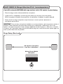
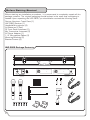
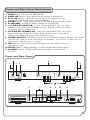
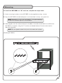
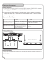
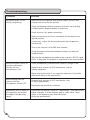
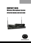
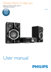
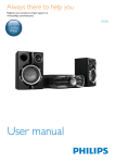
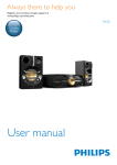
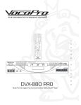
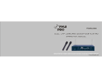
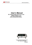
FEATURES:
•
Four Dual-Channel Frequency Presets for a Total of 8 Selectable Channels for
Trouble-free UHF Operation
Interference-resistant UHF Band Operation from 520 - 570 MHz
•
Detachable Front-Panel and Mic-Transmitter RF Antennas
•
Independent Front-Panel Volume Control and Channel Selection
•
Included Mounting Brackets for Easy Rack Mounting
•
Rugged 1RU Metal Receiver Housing
•
XLR Balanced and 1 / 4" Unbalanced Outputs with Separate/Mixed Output Options
•
110V-240V Switchable
s
m
a
n
u
a
l
•
-30
-15
-5
0
+5
+15
-30
-15
-5
0
+5
+15
AF
r
AF
'
8-Channel Dual UHF Wireless Microphone System
ANT-B
e
LEVEL-B
n
LEVEL-A
w
POWER
o
ANT-A
UHF-3800
8 Channel UHF Dual Wireless Microphone System
Safety Instructions
CAUTION
RISK OF SHOCK
CAUTION: To reduce the risk of electric shock,
do not remove cover (or back). No userserviceable parts inside. Only refer servicing to
qualified service personnel.
Explanation of Graphical Symbols
The lightning flash & arrowhead
symbol, within an equilateral triangle,
is intended to alert you to the
presence of danger.
The exclamation point within an
equilateral triangle is intended to alert
you to the presence of important
operating and servicing instructions.
WARNING
To reduce the risk of fire or electric shock, do
not expose this unit to rain or moisture.
8. Ventilation - The appliance should be situated so its
location does not interfere with its proper ventilation. For
example, the appliance should not be situated on a bed,
sofa, rug, or similar surface that may block the
ventilation slots.
9. Heat - The appliance should be situated away from
heat sources such as radiators, heat registers,
stoves, or other appliances (including amplifiers)
that produce heat.
10. Power Sources - The appliance should be
connected to a power supply only of the type described
in the operating instructions or as marked on the
appliance.
11. Grounding or Polarization - Precautions should be
taken so that the grounding or polarization means of
an appliance is not defeated.
12. Power-Cord Protection - Power-supply cords
should be routed so that they are not likely to be walked
on or pinched by items placed upon or against them,
paying particular attention to cords at plugs,
convenience receptacles, and the point where they exit
from the appliance.
13. Cleaning - Unplug this unit from the wall outlet
before cleaning. Do not use liquid cleaners or
aerosol cleaners. Use a damp cloth for cleaning.
14. Power lines - An outdoor antenna should be
located away from power lines.
1. Read Instructions - All the safety and operating
instructions should be read before the appliance is
operated.
15. Nonuse Periods - The power cord of the appliance
should be unplugged from the outlet when left unused
for a long period of time.
2. Retain Instructions - The safety and operating
instructions should be retained for future reference.
16. Object and Liquid Entry - Care should be taken so
that objects do not fall and liquids are not spilled into the
enclosure through openings.
3. Heed Warnings - All warnings on the appliance and in
the operating instructions should be adhered to.
4. Follow Instructions - All operating and use
instructions should be followed.
5. Attachments - Do not use attachments not
recommended by the product manufacturer as they may
cause hazards.
6. Water and Moisture - Do not use this unit near water.
For example, near a bathtub or in a wet basement and
the like.
7. Carts and Stands - The appliance should be used
only with a cart or stand that is recommended by the
manufacturer.
7 A. An appliance and cart combination
should be moved with care. Quick stops,
excessive force, and uneven surfaces may
cause an overturn.
1
17. Damage Requiring Service - The appliance should
be serviced by qualified service personnel when:
A.
B.
C.
D.
The power supply cord or plug has been damaged; or
Objects have fallen into the appliance; or
The appliance has been exposed to rain; or
The appliance does not appear to operate normally
or exhibits a marked change in performance; or
E. The appliance has been dropped, or the enclosure
damaged.
18. Servicing - The user should not attempt to service
the appliance beyond that described in the operating
instructions. All other servicing should be referred to
qualified service personnel.
Note:
To CATV system installer's (U.S.A.): This reminder is
provided to call the CATV system installer's attention to
Article 820-40 of the NEC that provides guidelines for
proper grounding and, in particular, specifies that the
cable ground shall be connected as close to the point of
cable entry as practical.
Welcome!
Thank you for purchasing the UHF-3800 from VocoPro, your ultimate choice in
Karaoke entertainment! With years of experience in the music entertainment business,
VocoPro is a leading manufacturer of Karaoke equipment, and has been providing
patrons of bars, churches, schools, clubs and individual consumers the opportunity to
sound like a star with full-scale club models, in-home systems and mobile units. All our
products offer solid performance and sound reliability, and to further strengthen our
commitment to customer satisfaction, we have customer service and technical support
professionals ready to assist you with your needs. We have provided some contact
information for you below.
VocoPro
1728 Curtiss Court
La Verne, CA 91750
Toll Free: 800-678-5348
TEL: 909-593-8893
FAX: 909-593-8890
VocoPro Company Email Directory
Customer Service & General Information
[email protected]
Remember Our Website
Tech Support
[email protected]
Be sure to visit the VocoPro website www.vocopro.com for the latest information on new
products, packages and promo's. And while you're there don't fo rget to check out our
Club VocoPro for Karaoke news and events, chat rooms, club directories and even a
Service directory!
We look forward to hearing you sound like a PRO, with VocoPro, your ultimate choice in
Karaoke entertainment.
FOR YOUR RECORDS
Please record the model number and serial number below, for easy reference, in case of loss or theft. These numbers
are located on the rear panel of the unit. Space is also provided for other relevant information
Model Number
Serial Number
Date of Purchase
Place of Purchase
2
UHF-3800
UHF-3800
8-Channel
UHF Wireless
Microphone System
Contents
Safety Instructions......................................................................... 1
Welcome.......................................................................................
2
Features.......................................................................................
3
Listening for a Lifetime...................................................................
4
Microphone Basics.........................................................................
5
UHF-3800 & Stage Monitor/P.A. Loudspeakers................................
6
Before Getting Started................................................................... 7
Front and Rear Panel Descriptions................................................... 8
Microphone Description and Functions.............................................
9
Mounting....................................................................................... 10
Getting Connected.......................................................................... 11
Operations..................................................................................... 12
Tips for Achieving Optimum Performance.......................................... 13,14
Troubleshooting.............................................................................. 15
Specifications................................................................................
16
FEATURES:
• Four Dual-Channel Frequency Presets for a Total of 8 Selectable Channels for
Trouble-free VHF Operation
• Interference-resistant UHF Band Operation from 520 - 570 MHz
• Detachable Front-Panel and Mic-Transmitter RF Antennas
• Independent Front-Panel Volume Control and Channel Selection
• Included Mounting Brackets for Easy Rack Mounting
• Rugged 1RU Metal Receiver Housing
• XLR Balanced and 1 / 4" Unbalanced Outputs with Separate/Mixed Output Options
• 110V-240V Switchable
3
Listening For A Lifetime
Listening for a Lifetime
Selecting fine audio equipment such as the unit you've just purchased is only the
start of your musical enjoyment. Now it's time to consider how you can maximize the
fun and excitement your equipment offers. VocoPro and the Electronic Industries
Association's Consumer Electronics Group want you to get the most out of your
equipment by playing it at a safe level. One that lets the sound come through loud
and clear without annoying blaring or distortion and, most importantly, without
affecting your sensitive hearing.
Sound can be deceiving. Over time your hearing "comfort level" adapts to a higher
volume of sound. So what sounds "normal" can actually be loud and harmful to your
hearing. Guard against this by setting your equipment at a safe level BEFORE your
hearing adapts.
To establish a safe level:
• Start your volume control at a low setting.
• Slowly increase the sound until you can hear it comfortably and clearly, and without
distortion.
Once you have established a comfortable sound level:
• Set the dial and leave it there.
• Pay attention to the different levels in various recordings.
Taking a minute to do this now will help to prevent hearing damage or loss in the
future. After all, we want you listening for a lifetime.
Used wisely, your new sound equipment will provide a lifetime of fun and enjoyment.
Since hearing damage from loud noise is often undetectable until it is too late, this
manufacturer and the Electronic Industries Association's Consumer Electronics
Some common decibel ranges:
Level
Example
304
050
607
080
Quiet library, Soft whispers
Living room, Refrigerator, Bedroom away from traffic
Light traffic, Normal Conversation
Air Conditioner at 20 ft., Sewing machine
Vacuum cleaner, Hair dryer, Noisy Restaurant
Average city traffic, Garbage disposals, Alarm clock at 2 ft.
The following noises can be dangerous under constant exposure:
Level
Example
901
001
201
401
80
Subway, Motorcycle, Truck traffic, Lawn Mower
Garbage truck, Chainsaw, Pneumatics drill
Rock band concert in front of speakers
Gunshot blast, Jet plane
Rocket launching pad
-Information courtesy of the Deafness Research Foundation
4
Microphone Basics
Microphone Position
The UHF-3800 is ideal for close-up vocals and can be held in the hand or mounted on a mic stand.The
most common applications and placement techniques are listed below. Keep in mind that microphone
technique is largely a matter of personal taste, there is no one "correct" microphone position.
Proximity Effect
When the sound source is less than 1/4 in. from the microphone, the microphone boosts bass
frequencies (by 6 to 10 dB at 100 Hz), creating a warmer and richer bass sound than when farther
away. This effect, known as proximity effect, happens only in unidirectional dynamic microphones
like the UHF-3800.
Feedback
Feedback occurs when the amplified sound from any loudspeaker reenters the sound system through
any open microphone and is amplified again and again and again. Most commonly, feedback is caused
by the following conditions: placing loudspeakers too close to microphones, having too many open
active microphones, boosting tone controls indiscriminately (mainly treble) and performing in areas
with high ratios of room surfaces that have hard and reflective surfaces such as glass, marble and
wood. What to do if feedback occurs before the sound system is loud enough?
• Request that the talker speak louder into the microphone.
• Reduce the distance from the talker to the microphone. Each time this distance is halved, the sound
system output will increase by 6dB.
• Reduce the number of open microphones.
• Move the loudspeaker farther away from the microphone. Each time this distance is doubled, the
sound system output can be increased by 6dB.
• Move the loudspeaker closer to the listener.
• Use an equalizer/feedback reducer to cut the frequency bands in which the feedback occurs.
Microphone Placement & Tone Quality
Lead & Backup Vocals
Lips should be less than 3" from or even touching the windscreen on an axis to the microphone.
Doing this creates a robust sound, emphasizes bass and provides maximum isolation from
other sources.
Speech
When giving a speech or simply speaking, place the microphone 4" to 10" away from the mouth, just
above nose height for a natural sound with reduced bass. You can also place the microphone
8" to 16" away from the mouth, slightly off to one side, for a more "distant" sound with highly
reduced bass and minimal "s" sounds.
5
UHF-3800 & Stage Monitor/P.A. Loundspeakers
If you will be using the UHF-3800 with stage monitors and/or P.A. system, try the following:
• Place the stage monitor directly behind the microphone.
• Locate the P.A. loudspeakers so that they point away from the rear of the microphone.
(With the speakers located in these positions, the possibility of feedback is greatly reduced).
• Always check the stage setup before a performance to ensure optimum placement of
microphone and monitors.
IMPORTANT: Every wireless microphone installation is a unique situation, and can present a variety of
problems. Never attempt a live performance without first conducting a "walkthrough" test of the
system in the performing area. If major changes (additional wireless systems or intercoms, relocation
of scenery, etc.) have been made since the last walk-through test, check the wireless system again, as
close to performance time as possible.
Stage Setup (Overhead)
P.A. Speakers Facing Away
From Rear of Microphone
Monitor Directly Behind
Microphone
6
Before Getting Started
Before starting any installation procedures, it is recommend to completely unpack all the
package contents. The original packaging should be kept in the event that re-shipping is
needed. Upon unpacking the UHF-3800, you should have received the following items:
Custom Aluminum Travel Case (1)
UHF-3800 Receiver (1)
Handheld Microphones (2)
AA Batteries (2 Pair)
RF Front Panel Antennas (2)
Mic Transmitter Antennas (2)
AC Power Adapter (1)
1/4" Microphone Cables (2)
Mounting Brackets (2)
Bracket Screws (6)
UHF-3800 Package Contents
8-Channel Dual UHF Wireless Microphone System
-30
-15
-5
0
+5
+15
-30
AF
ANT-A
7
POWER
LEVEL-A
-15
-5
0
+5
+15
AF
LEVEL-B
ANT-B
Front and Rear Panel Descriptions
1. POWER button - Turns the UHF-3800 ON/OFF.
2. POWER LED indicator - Glows BLUE when the receiver is powered ON.
3. RF/AF LED indicator - Lights RED when RF signals are received from the
microphone channels and output to external devices.
4. VOLUME controls - These controls adjust the VOLUME level for each MIC channel.
5. RF ANTENNAS - Provides RF SIGNAL reception to the RECEIVER.
6. 1/4" AUDIO OUT (MIXED A-B) - This ¼" unbalanced OUTPUT jack is for output
connection to amplifiers, effects devices or mixers. Both Mic channels are output
through this jack for mixed output.
7. XLR AUDIO OUT (SEPARATE A-B) - These XLR unbalanced OUTPUT jacks are for
output connections to amplifiers, effects devices and/or mixers. These are for
separate mic channel connections with unmixed mic output.
8. CHANNEL SELECTOR - This selects one of the four dual-channel frequency pre-sets. The receiver
and mics must all be set to the same pre-set. For example, if this is set to "1", both mics must
also have their channels set to "1" to work.
9. FUSE terminal - This terminal houses the system fuse. Only replace with same
type/rating of fuse.
10. VOLTAGE selector - Selects between 110-120V and 220-240V power settings.
11. AC POWER terminal - MAINS POWER jack for connection to a compatible
AC outlet.
Front and Rear Panel
5
1
4
2
5
8-Channel Dual UHF Wireless Microphone System
-30
-15
-5
0
+5
+15
-30
-15
-5
0
AF
ANT-A
LEVEL-A
POWER
+5
+15
AF
LEVEL-B
ANT-B
3
7
6
8
BALANCED OUTPUT
AUDIO OUTPUT
SERIAL NO:
FREQUENCY
A: 564.2-575.9Mhz
B: 545.2-554.6Mhz
MIXED A/B
!
MIC-B
MIC-A
11
CAUTION
RISK OF ELECTRICAL SHOCK
DO NOT OPEN
CAUTION: TO REDUCE THE RISK OF
FIRE. REPLACE ONLY WITH THE SAME TYPE
AND RATING OF FUSE
ATENTION: UTILISER UN FUSIBLE DE
RECHANGE DE MEMETYPE
UNBALANCED
10
CHANNEL 1234
110V
8-Channel Dual UHF Wireless Microphone System
9
AC: 110V/240V
VOLTAGE SELECTOR
AC240V
LA VERNE CALIFORNIA
U.
S.
A
50/60Hz
AC110V
1.5A
DC 12V 2A FUSE
AC INPUT
www.vocopro.com
8
Microphone Descriptions and Functions
UHF-3800 Microphone
1
3
4
5
2
LED ON OFF
STANDBY
ANT.
MIC
A
1.
2.
3.
4.
GRILL - Protects the microphone cartridge and helps reduce "breathy" and wind noise pick- up.
POWER switch - Used to turn the microphone ON/OFF and place in STANDBY.
BATTERY COMPARTMENT lid - Removable lid hides and protects the microphone battery.
CHANNEL selector (internal) - Used to sync the Mic transmitters outgoing frequency with the
receivers channels pre-set for Mic operation. For each Mic (A-B), the channel setting must be
set to the same number on the Mic as it is on the receiver. For example, MIC's A and B = Mic
channel setting 1, Receiver channel setting = 1.
5. ANTENNA terminal - Accepts the Mic transmitter ANTENNA used for UHF transmission.
Handheld Microphone Antenna Installation
1. Screw the ANTENNA into the ANTENNA TERMINAL on the bottom of each Mic transmitter.
Handheld Microphone Battery Installation
2. Unscrew the microphones BATTERY COMPARTMENT LID located at the bottom
of the microphone.
3. Insert 2 fresh 1.5-volt alkaline BATTERIES, being sure to observe proper battery polarity.
4. Re-tighten the BATTERY COMPARTMENT LID.
Battery Installation
BATTERY COMPARTMENT
BATTERY LID
BATTERY COMPARTMENT CLOSED
BATTERY COMPARTMENT
9
BATTERY
Mounting
To install the UHF-3800 to a 19" rack case, complete the steps below.
1. Attach mounting brackets to the UHF-3800 via the supplied mounting screws.
2. Align the UHF-3800 with desired space in rack and slide in slowly, rear panel first.
.
NOTE: Depending on your rack case design, it may be necessary
to allow for sufficient space for the antennas.
3. While aligned, use rack case screws (not included) in the order shown below to stabilize the
UHF-3800 in its space, using the "X" rotation (numbered below) will ensure even tension
and plush alignment.
NOTE: Do not tighten screws firmly until all screws are in place.
(See diagram below)
10
Getting Connected
System Connection
1. Connect the AC POWER ADAPTER to the UHF-3800 receiver's POWER INPUT connector;
then plugging the ADAPTER into a compatible AC electrical outlet.
2. Connect the UHF-3800s receiver to a sound system, mixer or amplifier's microphone
input(s) with either one ¼" output jack for a mixed channel output, or both XLR output
jacks for separate output.
Separated or Mixed Output
Pros
Cons
Uses only 1 mic input on an
external mixer/amplifier
Mixed Channel Output
External mic adjustements
can be applied on one or
both mic channels
Separate Channel Output
External mic adjustments applied
to just one mic channel
Uses 2 mic inputs on mixer/
amplifier
Getting Connected
Connections
BALANCED OUTPUT
CAUTION
RISK OF ELECTRICAL SHOCK
DO NOT OPEN
FIRE. REPLACE ONLY WITH THE SAME TYPE
AND RATING OF FUSE
ATENTION: UTILISER UN FUSIBLE DE
AC: 110V/240V
VOLTAGE SELECTOR
AC240V
B: 545.2-554.6Mhz
MIXED A/B
MIC-B
MIC-A
CHANNEL 1234
LA VERNE CALIFORNIA
U.
S.
A
50/60Hz
AC110V
RECHANGE DE MEMETYPE
FREQUENCY
A: 564.2-575.9Mhz
!
CAUTION: TO REDUCE THE RISK OF
UNBALANCED
SERIAL NO:
110V
8-Channel Dual UHF Wireless Microphone System
AUDIO OUTPUT
1.5A
DC 12V 2A FUSE
AC INPUT
www.vocopro.com
Antenna Attachment
Mic
Input
Mic
Input
Mic
Input
To Outlet
8-Channel Dual UHF Wireless Microphone System
-30
-15
-5
0
+5
+15
-30
AF
ANT-A
POWER
LEVEL-A
-15
-5
0
+5
+15
AF
LEVEL-B
ANT-B
OR
Antenna Connection
1. Insert the ANTENNAs BNC connector into the BNC jack and twist counter-clockwise till it
locks into place.
11
Operations
1. Press the POWER button on the UHF-3800 receiver's front panel. The power
LED on the receiver will glow BLUE.
2. Adjust the receive's VOLUME controls to approximately 50%.
3. Switch the microphone's POWER BUTTONS to the ON positions.
4. Talk or sing into the microphones. During normal operation, the RF/AF signal
LED's will light RED when a microphone is being used.
5. Adjust the receiver's VOLUME controls until the output levels are balanced
with eachother and other possible source output i.e. CD+G tracks. In most
cases, the VOLUME controls should be set to +/-65%.
Receiver Volume Adjustment
The VOLUME controls on the front panel of the UHF-3800 receiver can be adjusted
to set the wireless system OUTPUT levels as you desire. After making any musical
balancing adjustments, adjust the receiver volume control until the output reaches
the desired level. Perform this with both MIC channels if they are both to be in use.
Rotate the volume control clockwise to increase output. Rotate it counterclockwise to
decrease output.
12
Tips for Achieving Optimum Performance
Recognizing Interference
The ways of recognizing the type of interference present are observing the RF/AF
LED indications and carefully listening to the audio output. A set of headphones can
be a useful tool in isolating and analyzing interference problems. With headphones it
is easier to listen to one wireless channel at a time, even when the system is in use.
Below are some common interference descriptions. Most likely, one of the below
descriptions matches the symptoms that you may be experiencing.
If there is interference when the microphones are off, and the noise/distortion is
present from the receiver output when the microphones are powered on, try
turning off all other wireless microphones. If the interference problem is still
present, there might be a direct radio interference problem. Direct interference
is a serious problem that must be corrected in order for the wireless system to
be fully usable.
• Interference in the form of low level-audio tones, whines, whining sounds
whose pitch changes rapidly, or audible voices or music (distorted or not) is
likely to be caused by intermodulation, non-wireless interference or direct
interference.
• If there is interference when the receiver is turned on, in the form of buzzy or
raspy whines with a distinct cadence or rhythm that differs from time to time,
digital interference might be the problem. Common sources include computers,
digital delays, effects processors, lighting controllers, and other digital
equipment using microprocessors and digital signal processors (DSPs).
• If there is no interference when the receiver is turned off and irregular popping,
cracking or buzzing noises on the audio with the receiver on, there may be
electrical interference problems. This kind of interference is usually caused by
electric motors, neon lights, lighting equipment, appliances and other types of
electrical equipment. Electrical interference will generally affect all wireless
systems at a location, not just one system.
• Certain types of buzzing sounds are actually due to interference from TV
stations. If the buzzing sound changes substantially at more or less random
intervals and does not seem to be caused by electrical equipment, the problem
may be TV interference.
• Interference that takes the form of bursts of static or short bursts of noise is
likely to be caused by lightning, intermittent arcing or defective electrical
machinery. This type of random interference is quite rare but can be among the
most difficult to resolve.
•
(cont.)
13
Tips for Achieving Optimum Performance (cont.)
If none of the descriptions matches your particular problem, or the information is
unclear, see the "Avoiding Basic Problems/UHF Frequency Conflicts" sections below.
Your authorized dealer may also be able to offer assistance and might be familiar with
any unusual local conditions that could be affecting the problem. If your dealer is not
able to assist, owners of VocoPro equipment can obtain telephone support at:
800-678-5348 9A-5P M-F Pacific Time.
Avoiding Basic Problems
Sometimes interference problems have very basic causes. To avoid wasting time on
an easily correctable problem, check the following items before proceeding:
Make certain than no radio transmitters are allowed to come closer than
approximately 10 to 15 feet of the wireless receiver antennas. This can
overload the receiver and increase the chances of interference.
• Make certain not to allow receiver antennas to touch each other when arranging
them. Try to provide at least 10 inches of separation between the antennas of
any two receivers.
• Make sure that all microphones have charged batteries. The low output voltage
of weak batteries can cause some microphones to generate harmful
interference. If there is any doubt, install fresh batteries in all microphones.
• Make sure that the wireless frequencies are not on a local TV channel.
• Check the wireless frequencies in use to make sure that no two systems are on
the same frequency.
• Check to make sure that no two wireless frequencies are too close together. In
general, 1 MHz is the recommended minimum spacing between systems.
• If a considerable number of systems will be used, operating conditions will be
difficult or interference is likely, if possible avoid these situations.
• Before using a system in a new location or another city, double-check for new
problems. Small changes in conditions can cause interference where none was
present before.
• Turn off unnecessary electronic equipment, especially computers and digital
devices. These are a relatively common cause of wireless interference.
• If use of computers or digital devices is necessary, keep them at least 18
inches (45 cm) away from the microphones and receiver antennas.
•
UHF Frequency Conflicts
The primary way that UHF wireless systems experience interference, is direct
frequency conflict. If two UHF wireless systems are on the same frequency, usually
neither system will be usable unless the other is turned off. This problem is not as
common as might be expected, due to the non-crowded nature of the UHF band and
the multi-channel/frequency selection found on many UHF systems.
14
Troubleshooting
Problems
No sound output, RF/AF
LED(s) not glowing.
Solutions
• Make sure the microphone and receiver power switches and
receiver are set to the ON position.
• Check microphone batteries to ensure that they are providing
sufficient power. Replace battery if necessary.
• Check receiver's AC power connection.
• Make sure antennas are firmly connected and extended to an
optimal position.
• If necessary, reduce the distance between the microphones
and receiver.
• Turn up the receiver's VOLUME level controls.
• Check for proper connection between receiver and external
amplifier/mixer.
• Talk into the microphone and observe the receiver's RF/AF signal
LED's. If they glow, the problem is elsewhere in the sound system.
Received signal is noisy or
contains extraneous
sounds with the
microphone(s) ON.
• Check microphone(s) batteries and replace if charge is low.
• Remove local sources of UHF interference, such as
lighting equipment.
• Signal may be too weak. If so, reposition antennas. (If possible,
move them closer to the transmitter).
Noise coming from the
receiver with the
microphones turned OFF.
• Remove local sources of UHF interference, such
as lighting equipment.
• Reposition the receiver or antennas.
Momentary loss of sound as • Reposition the receiver, perform a "walkthrough", and observe the
microphone(s) are moved
signal strengths. If audio dropouts persist, mark these "dead
throughout the operating
spots" in the operating area and avoid them
range.
during the performance.
15
Specifications
RF Carrier Frequency Channel
520M-570M(8 channels, work at the same time)
If the user has a special demand, we can have the frequency made to order.
Service Area:
100m(ground)
Transmit
Frequency Response:
Audio-head FR: 50-16kHz±3dB
Without Audio-head FR: 20-20kHz±3dB
Modulation:
±75kHz
RF Power:
20mW
Dynamic Area:
>102dB
Electric Level Output:
Typical±5dBu(unbalanced output)
Typical±14dBu(balanced output)
Polarity(Microphone):
Exert pressure at the front of cartridge, to generate electric pressure.
Receiver
Sensitivity:
0.2 V(@12dB SinAD)
Pseudomorph Modulation:
Typical 90dB
Stray modulation:
Typical 75dB
Limited Mute:
>100dB(15kHz Frequency offset)
System Distortion:
0.3% Total harmonic distrortion, Typical, @1kHz signal 4.5kHz frequency offset.
Battery
Handheld Microphone:
1.5V AA battery
Receiver:
110V-220V (with changeover switch)
Service life of battery:
1.5V AA high-energy battery can be worked more than 13hrs.
Working Temperature:
-20°C-50°C(Make sure the battery can exceed this norm.)
16
www.vocopro.com