1
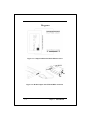
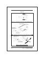
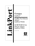
Compex LinkPort PCMCIA Ethernet Card ENET-B User’s Manual Version 1.7C Compex LinkPort PCMCIA Ethernet Card ENET-B User’s Manual Version 1.7C Manual Number: M-0011-V1.7C Manual Release Date: October 1999 Printed in the Republic of Singapore i Disclaimer Compex, Inc. provides this guide without warranty of any kind, either expressed or implied, including but not limited to the implied warranties of merchantability and fitness for a particular purpose. Compex, Inc. may make improvements and/or changes to the product and/or specifications of the product described in this guide, without prior notice. Compex, Inc. will not be liable for any technical inaccuracies or typographical errors found in this guide. Changes are periodically made to the information contained herein and will be incorporated into later versions of the guide. The information contained is subject to change without prior notice. Trademark Information Compex®, LinkPort® and ReadyLINK® are registered trademarks of Compex, Inc. All brand and product names are trademarks or registered trademarks of their respective owners. Notice Copyright © 1997 by Compex, Inc.. All rights reserved. Reproduction, adaptation, or translation without prior permission of Compex, Inc. is prohibited, except as allowed under the copyright laws. Manual Revision by Leon Enriquez Important Information The latest updates and changes after the release of this manual can be found in the RELEASE.TXT file in the latest Compex LinkPort release diskette. ii DECLARATION OF CONFORMITY Manufacturer’s Name: Manufacturer’s Address: Compex, Inc. 4051 E. La Palma, Unit A Anaheim, CA 92807 U S A Compex, Inc. declares that the product: Product Name: Compex LinkPort, PCMCIA Ethernet Card Model Number: ENET-A conforms to the following Product Standards: Radiated Emission Standards: Conducted Emission Standards: Immunity Standards: EN55022B FCC Part 15 Class B EN60555PT2 conducted emission EN55022B conducted emission FCC Part 15 Class B IEC 801-2 IEC 801-3 IEC 801-4 Therefore, this product is in conformity with the following regional standards: FCC Class B — following the provisions of FCC Part 15 directive. CE Mark — following the provisions of the EC directive. Singapore, October 1999 _______________________ Dr Jackson Lam, R & D Manager European Contact: ReadyLINK Networktechnology Gmbh, Technical Support, Albert Einstein Straβe 42, 63322 Rödermark, Germany. [FAX: +49 (60) 749-0668] iii FCC Notice This device has been tested and found to comply with the limits for a Class B digital device, pursuant to Part 15 of the FCC Rules. These limits are designed to provide reasonable protection against harmful interference in a residential installation. This device generates, uses and can radiate radio frequency energy and, if not installed and used in accordance with the instructions, may cause harmful interference to radio communications. However, there is no guarantee that interference will not occur in a particular installation. If this device does cause harmful interference to radio or television reception, the user is encouraged to try to correct the interference by one or more of the following measures: p Reorient or relocate the receiving antenna. p Increase the separation between the computer and receiver. p Connect the computer into an outlet on a circuit different from that to which the receiver is connected. p Consult the dealer or an experienced radio/TV technician for help. Caution: Any changes or modifications not expressly approved by the grantee of this device could void the user's authority to operate the equipment. FCC Compliance Statement This device complies with Part 15 of the FCC Rules. Operation is subject to the following two conditions: (1) This device may not cause harmful interference, and (2) This device must accept any interference received, including interference that may cause undesired operation. iv Contents Chapter 1: Introduction 1-1 Chapter 2: Installing the Adapter 2-1 Chapter 3: Software Installation 3-1 Appendix A: Technical Information A-1 Appendix B: Technical Support B-1 v NOTES vi Chapter 1 Introduction The Compex LinkPort PCMCIA (Personal Computer Memory Card International Association) Ethernet card [ENET-B] is a credit card sized network adapter that can be used for PCMCIA compliant personal computers. The Compex LinkPort PCMCIA Ethernet card plugs into a Type II PCMCIA slot, providing a 16-bit bus interface. The card is switchless, software configurable, and provides full support for the PCMCIA Card Information Structure (CIS). The card is supplied with a media coupler that provides a BNC coaxial 10Base-2 connector, and a UTP (Unshielded Twisted-Pair) 10Base-T connector. Also included is an intelligent Enabler program that automatically detects your PC’s controller type and recognises previously installed card and socket services. Compex LinkPort PCMCIA Ethernet Card Features 1-2 ≥ Conforms to IEEE 802.3, PCMCIA Release 2.1, JEIDA 4.1 Standard. ≥ Fits into Type II PCMCIA slot. ≥ Provides 68-pin connector for attachment to PC and 15-pin flat connector for attachment to media coupler. ≥ Media coupler incorporates RJ-45 10Base-T UTP connector and BNC 10Base-2 coaxial connector. ≥ Switchless design; hardware settings are software configurable. ≥ Low power consumption. ≥ Extensive software driver support which includes drivers for Novell NetWare; NDIS driver for Microsoft LAN Manager; drivers for Microsoft Windows for Workgroups, Windows 95, Windows NT v3.51, Windows NT v4.0; Packet Driver applications; LANtastic v6.0; and IBM OS/2 Warp. (Refer to the driver diskette for the latest updated list.) Chapter 1: Introduction Hardware Description ≥ PCMCIA card The Compex LinkPort PCMCIA Ethernet card’s main PCB board is encased in a stainless compact frame. It has a 68-pin connector that fits into a PCMCIA socket,. and a 15-pin flat connector that connects to the media coupler. ≥ Media Coupler Media coupler incorporates RJ-45 10Base-T UTP connector and BNC 10Base-2 coaxial connector. ≥ LED Indicators ↵ ACT LED (Colour: orange) Function: Monitors signals transmitted to and received from the network. The orange LED, labelled ACT, lights up to indicate that the PCMCIA Card is transmitting signals to and/or receiving signals from the network. This LED is normally OFF. It will flash when the card transmits signals to the network. The speed at which the LED flashes increases with the level of network traffic. ↵ LINK LED (Colour: green) Function: Monitors link status of twisted-pair connection. The PCMCIA Card supports the link integrity test function. This function is automatically enabled when the card is configured for RJ-45 UTP cabling. The green LED, labelled LINK, lights up to indicate that a valid 10Base-T link has been established. It is ON under normal operating conditions. If the LED is OFF, check the RJ-45 port’s cable connection. Note: The LINK LED only monitors the 10Base-T (R J-45) connection. To check the condition of the BNC link, run the diagnostics program. Chapter 1: Introduction 1-3 Diagrams Figure 1-1: Compex LinkPort PCMCIA Ethernet Card Figure 1-2: Media Coupler with UTP and BNC connectors 1-4 Chapter 1: Introduction Chapter 2 Installing the Adapter This chapter describes the procedure for installing the Compex LinkPort PCMCIA Ethernet Card. Procedure: 1. Power OFF the host computer. 2. Insert the Compex LinkPort PCMCIA Ethernet Card into the computer’s PCMCIA slot. Insert the 68-pin connector on the card into the computer’s PCMCIA slot. The label on the card should face up. Slide the card all the way into the slot. 3. Plug the media coupler into the card’s 15-pin connector. 4. Connect the media coupler to the network. p Using UTP cable or p Using BNC cable p Using UTP (10Base-T) cable: Plug the free end of the UTP cable into a RJ-45 mating connector on a twisted-pair hub, or into a network access port. Compex LinkPort PCMCIA Ethernet Card p Using BNC (thin coaxial) cable: Using thin coaxial cable: Connect a T-connector to the BNC connector on the media coupler. Attach both ends of the T-connector to thin coaxial cables. If the card is at the end of the network segment, install a 50-ohm terminator at the open end of the T-connector. Do this carefully to prevent accidental shorts which may disrupt network operation. 5. Power ON the PC. Hardware installation is now complete. Switch ON the PC. The Compex LinkPort PCMCIA Ethernet Card receives its power from the PC. Warning: To avoid accidents, do not connect or disconnect cables, or perform installation or maintenance of the card during an electrical storm. Removing the Card: Procedure: To remove the Compex LinkPort PCMCIA Ethernet Card from the PC, do as follows: 2-2 1. Power OFF the machine. 2. Remove from the coupler the UTP cable from the RJ-45 socket; or if coaxial cable, the T-connector from the BNC socket. Chapter 2: Installing the Adapter 3. Remove the media coupler from the Compex LinkPort PCMCIA Ethernet Card. To do this, squeeze the locking arms on either side of the coupler-to-card connector. Pull to unplug the media coupler. 4. Remove the card from the slot. Store it together with the coupler in a safe place. Chapter2: Installing the Adapter 2-3 Diagrams Figure 2-1: Inserting the Card into the Type II PCMCIA socket Figure 2-2: Plug the 15-pin connector to the 15-pin mating connector Figure 2-3: BNC Coaxial connection 2-4 Chapter 2: Installing the Adapter Chapter 3 Software Installation Introduction: Enabler program: Lanenb.EXE ↵LANENB enabler is provided to configure Compex LinkPort ENET-B in DOS environment. ↵Before any driver (either loaded from Config.sys or Autoexec.bat or any batch file) can initialize the adapter, LANENB must be run first to configure it. ↵If PCMCIA Card and Socket Services software is run in the machine, LANENB.EXE must run immediately after this (Card and Socket Services) software is loaded, but before loading the network driver. ↵LANENB.EXE cannot be unloaded. The machine must reboot and LANENB.EXE re-run to change to a new I/O Address and Interrupt Number. To run LANENB.EXE, insert the driver diskette in drive A:\ and type the following: A:LANENB [/IRQ=dd] [/IOP=XXX] A:LANENB [/HLP] or [/?] A:LANENB [/CHK] where: [/IRQ] Interrupt line keyword of the adapter. [/IOP] I/O Base Address keyword of the adapter. dd is a one/two digit number representing the interrupt line (Valid value: 3, 4, 5, 7, 9, 10, 11*, 12, 15). [*Default IRQ] Compex LinkPort PCMCIA Ethernet Card XXX is a 3-digit hex number representing I/O port base address (Valid value: 200H to 3E0H in steps of 20H. MMMM Is a 4-digit hex number representing attribude mwmory address (Valid value: C800, CC00, D000, D400, D800, DC00) /? Help message Note: The default interrupt line number for the adapter is 5. Notebook computers with built-in sound chips may also be using this Interrupt value. If you encounter such a situation, it is best to configure the adapter to a another Interrupt number such as 10 or 11 to avoid any conflicts. Before beginning the installation procedure, make a backup Copy diskette and use the Copy for installation. Store the original diskette in a safe place. LANENB.EXE utility To configure the Compex LinkPort PCMCIA Ethernet Card properly, you should first run the LANENB.EXE utility. Enter the following at the DOS prompt: For example: LANENB.EXE /int:5 /port:300 The following message will appear: Socket: 0 IRQ Number: 05 I/O PORT BASE: 0300H Memory Address: D400H The Compex LinkPort PCMCIA Ethernet Card is now configured and you are ready to load the network drivers. 3-2 Chapter 3: Installing the Drivers Network Operating Systems (NOS) Installation steps for all the Network Operating Systems (NOS) connection are documented in the respective directories of the particular NOS, in the Driver Disk. Please refer to these documents to install the network driver for the adapter. As new and updated Network Operating Systems become available, update drivers and new release disk will be made available in the Compex Website, FTP site and BBS servers. For details, refer to Appendix B. Chapter 3: Installing the Drivers 3-3 NOTES 3-4 Chapter 3: Installing the Drivers Appendix A Technical Information Compex LinkPort PCMCIA Ethernet Card System Configuration PCMCIA compliant computers Standard Conformance IEEE 802.3 standard, PCMCIA release 2.1 Type II, JEDIA 4.1 Bus-Width 16-bit I/O Base Address 200H to 3E0H in steps of 20H; Default IOP: *300H Interrupt 3, 4, *5, 7, 9, 10, 11, 12, 15. (*Default IRQ) Media Coupler UTP RJ-45 and BNC connector. Card Dimensions 85mm x 54mm x 5mm Power Requirement BNC Transceiver: +5V/ 0.28A max.* (* typical); UTP: +5V/ 0.16A max. * Temperature 0°C to 55°C (standard operating); 32°F to 131°F. Humidity 10% to 90% (Non-condensing) (10Base-T) connector, coaxial (10Base-2) Compex LinkPort PCMCIA Ethernet Card NOTES A-2 Appendix A: Technical Information Appendix B Technical Support If you encounter a specific problem and need our assistance, this appendix explains how you can get Technical Support worldwide from Compex. When you have a problem When you encounter a problem, please do the following: ♦ Ensure that you have sent in the product’s Warranty Registration Card. The card qualifies you as being eligible for customer support. ♦ If there is a diagnostic program, run it. This helps identify the cause of the problem, which may be something you could repair by yourself. ♦ Contact your place of purchase to see if your network vendor can solve the problem. If your adapter is still not functioning correctly, seek help from our Technical Support Specialists. Before contacting technical support For faster service, get ready the following facts before you talk to our Technical Support Specialist. Compex LinkPort PCMCIA Ethernet Card ♦ A description of the problem. Include in your description, the sequence of events that led to the problem and the duration of the problem. State whether you can reproduce the problem. ♦ A list of the products software and hardware involved in the problem, e.g., your computer model and type, DOS version, and the type and version of network operating system (NOS) and other applications. ♦ Network information, including the network topology, type of cable used, size of network, number of workstations in the network, etc. ♦ The network adapter settings and the settings of the other adapters (if any) in the system. ♦ A list of all the recent system configuration changes, including hardware, operating system and application software, network and system administration procedures. With this information, our Technical Support Specialists will be better able to help you solve the problem. B-2 Appendix B: Technical Support Technical Support Centers Contact the technical support center that services your location. U.S.A., Canada, Latin America and South America * Write Compex, Inc. 4051 E. La Palma, Unit A Anaheim, CA 92807, USA (714) 630-7302 (8 a.m.-5 p.m. Pacific time) (714) 630-6521 (714) 630-2570 (24-hour access) ( Call Tel: Fax: BBS: * Write ReadyLINK Networktechnology Gmbh Fax Europe Albert Einstein Straβe 42 63322 Rödermark, Germany ++49 (0) 6074 - 98017 (8 a.m.-5 p.m. local time) Tel: ++49 (0) 6074 - 90668 Fax: BBS: ++49 (0) 6074 - 93974 (24-hour access) Fax ( Call Asia, Australia, New Zealand, Middle East and the rest of the World * Write Fax ( Call Internet access/ Website: Compex Systems Pte Ltd 135, Joo Seng Road #08-01, PM Industrial Building Singapore 368363 (65) 286-1805 (8 a.m.-5 p.m. local time) Tel: (65) 283-8337 Fax: BBS: (65) 282-8854 (24-hour access) [email protected] ftp.compex.com.sg http://www.cpx.com or http://www:compex.com.sg E-mail: FTPsite: Appendix B: Technical Support B-3 NOTES B-4 Appendix B: Technical Support NOTES Appendix B: Technical Support B-5 Compex, Inc. 4051 E. La Palma, Unit A Anaheim, CA 92807 USA (714) 630-7302 1997 by Compex, Inc. All rights reserved. Printed in Singapore Compex LinkPort PCMCIA Ethernet Card ENET-B Manual Number: M-0011-V1.7C Version 1.7C October 1999 NOTES B-6 Appendix B: Technical Support