1
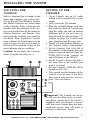
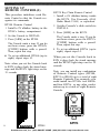
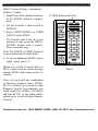
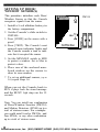
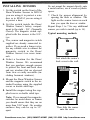
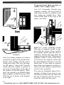
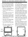
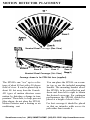
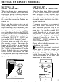
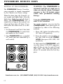
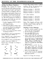
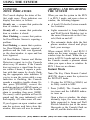
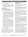
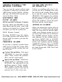
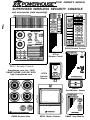
*p()WE’HO~I’E ‘y PS561 OWNER’S MANUAL
SUPERVISED WIRELESS SECURITY CONSOLE
and accessories (sold separately)
SH624 Remote Control
HT544
Remote Control
0
tm1
J
L
PS561 Security Console
Smarthome.com, Inc. (800)
SMART-HOME (949) 221-9200
http://smarthome.com
Yn
ORAY
m
0
cd.
I
KF574
Keychain
Remote
[-lo)
DW534
Door/Window Sensor
PH508 Remote Siren
SP554 Motion Detector
LM465 Lamp Module
CONTENTS
U.L. and F.C.C. Cautions
3
Introduction
4
5
Installing the System
Using the System
16
Console Indicators
16
Arming and Disarming
16
Locating the Console
5
INSTANT mode
16
Setting up the Console
5
DELAYED mode
17
Setting up Remote Controls
6
HOME/AWAY mode
17
HT544 Remote Control
6
Arm without Remote Control
18
KF574 Remote Control
4
Sounding the Panic Alarm
18
SH624 Remote Control
7
Trouble Alarm
18
8
Zones 9-16 Status Indication
18
After an Alarm
18
19
Setting up Sensors
Installing the Sensors
Looping Windows Together
9
10
Setting up Motion Detectors
11
Testing the Voice message
Testing the Dialer
19
Motion Detector placement 12
Turning Lights On and Off
20
Setting up Remote Modules
13
This is X-10 POWERHOUSE TM
21
Lamp Modules
13
Care and Maintenance
26
Wall Switch Modules
Replacing Batteries
Remote Controls
27
Setting up Remote Siren
13
14
Setting up Telephone Dialer
15
Door/Window Sensor
27
27
Phone Numbers
15
Motion Detector
28
Voice Message
15
Console
28
Troubleshooting
29
Smarthome.com, Inc. (800) SMART-HOME (949) 221-9200 http://smarthome.com
U.L. AND F.C.C. CAUTIONS
FCC Caution: This equipment generates
and uses radio frequency energy, and if not
installed and used properly, that is, in strict
accordance with the manufacturer’s instructions, may cause interference to radio and
television reception. It has been type tested
and found to comply with the limits for remote control security devices in accordance
with the specifications in subpart B of part
15 of FCC Rules, which are designed to
provide reasonable protection against such
interference in a residential installation.
However, there is no guarantee that interference will not occur in a particular installation. If this equipment does cause interference to radio or television reception,
which can be determined by unplugging the
equipment, the user is encouraged to try to
correct the interference by one or more of
the following measures.
Reorient antenna of the radio/TV
experiencing interference.
Relocate the Console with respect to
the radio/TV.
Move the Console away from the
radio/IV.
Plug the Console into an outlet on a
different branch circuit from the
radio/TV experiencing the interference.
If necessary, the user should consult the
dealer or manufacturer for additional suggestions.
Smarthome.com, Inc. (800)
SMART-HOME (949) 221-9200
http://smarthome.com
Important:
Your Security Console is FCC registered.
In order to fully comply with the FCC
rules, these instructions should be followed
prior to installing and using the product:
Connections cannot be made to coinoperated telephones, or to party lines.
The KC requires that any umnections
to telephone lines are to use standard
plugs and adaptors.
Notify the telephone company that you
will be connecting a Registered unit to
the line. Give them the following information regarding the Security Console:
A) FCC Registered Number
B4SUSA-65898-AL-T
B) Ringer Equivalence
0.lB.
3. If a problem arises with your telephone
service after you have connected the
Security Console, disconnect the unit to
see if the problem is caused by its use.
If the Security Console is at fault, leave
it disconnected until it is repaired or replaced. If the telephone company
makes a service call to your home and
determines that the Security Console
has caused the problem, they have the
right to charge you for a service call.
Note: The suitability of this product to perform as a burglar alarm system or as an
emergency service device has not been
evaluated by Underwriters Laboratories
Inc.
INTRODUCTION
The PS561 Security Console is part of
a Supervised Security System and is
used with the following accessories,
(sold separately).
Hand-held Remote Controls and
Key-chain Remote Controls for
arming and disarming the system
and for controlling lights and appliances around the home.
Door/Window Sensors with magnetic switch and magnet.
Passive Infrared Motion Detectors.
Lamp Modules for flashing house
lamps.
Wall Switch Modules for flashing
indoor and outdoor lights.
Remote 110-decibel siren.
You can add Door/Window Sensors to
protect up to 16 doors or windows, or
add a Motion Detector to protect an
area with more than one entry point.
When someone opens the door or window, or enters a protected area, the
Console sounds its alarm and sends
signals over the house wiring to flash
lights connected to X-10 Modules It
can also trip an additional loud remote
siren. The Console dials up to 4 preprogrammed phone numbers and plays
back up to 15 seconds of pre-recorded
message (in your voice). The person
called can then listen in to your home
to determine the nature of the problem.
You arm and disarm the system with
the Remote Control and you can add
up to a total of eight Remote Controls
which you can give to other family
members. You can also use the Remote Control to control lights and appliances around the home.
Features
Wireless Installation - makes it easy
to quickly make a home secure.
Sixteen-Zone System - lets you protect 16 different groups of doors and/
or windows in the home.
Remote Arm and Disarm - lets you
arm the system, turn on lights, or even
sound the alarm from anywhere in or
around the home.
Expandable Design - lets you add
more Door/Window Sensors and Motion Detectors to expand the system’s
coverage.
Fully Supervised Operation - so the
system keeps track of the status of
each Door/Window Sensor.
Built-in Voice Dialer - Dials a friend
or neighbor for help and plays back a
stored message (in your voice).
X-10 POWERHOUSE Compatible so you can add other Remote Controls
to the system or even add a timer to
make the home look lived-in while nobody is at home.
Smarthome.com, Inc. (800) SMART-HOME (949) 221-9200 http://smarthome.com
INSTALLING THE SYSTEM
LOCATING THE
CONSOLE
SETTING UP THE
CONSOLE
1. Plug the Console into an AC outlet
which is not controlled by a wall
switch.
2. Fully extend the RF antenna
3. Plug the included phone cord into
the socket on back of Console and
plug the other end into an unused
telephone jack. If you don’t have an
unused jack use the included "T"
adapter to plug the Console and
your telephone into the same jack.
4. Install a 9-volt alkaline battery in
the Console’s battery compartment.
5. Set the Console’s Unit Code dial to
the number of the module that you
Caution: Do not place the Console
want to turn on and off from the
where a burglar can easily see it.
HT544, KF574 or the “security” on
and off buttons on the SH624.
6. Set the Console’s Housecode dial to
Q
0
CD
the same letter as the modules you
want it to control.
7. Set the Console’s INSTALL/RUN
switch to INSTALL.
8. The switch on the bottom of the
Console is set for tone, if you don’t
have touch-tone service, set it to
pulse.
(See note below).
-0
Select a location that is central to the
doors and windows you wish to protect so that all Door/Window Sensors
and Motion Detectors are within range
of the Console. Later, when you are
familiar with the operation of the system you should test all the Sensors,
Motion Detectors, and Remote Controls from the locations you intend to
use them. Also, locate the Console
near a phone jack and where it can
easily be seen on a day to day basis so
that it will be noticed if any of the
zone indicators report a problem.
I
--I=--41
- @ Important: The Console can be set
to call out on either pulse or touchtone phone systems but if the friend or
neighbor who you choose to accept
calls from your system does not have
touch-tone service, they will need to
purchase a touch-tone ‘beeper.”
5
Smarthome.com, Inc. (800) SMART-HOME (949) 221-9200 http://smarthome.com
SETTING UP
REMOTE CONTROL(S)
This procedure initializes each Remote Control so that the Console recognizes its commands.
HT544 Remote Control
1. Install a 9V alkaline battery in the
HT544’s battery compartment.
2. Set the Console to INSTALL.
3. Press [ARM] on the HT544.
The Console emits a tone. If you do
not hear a tone, press the HT544’s
[CODE] button with a pencil.
Then, repeat this step.
4. To set up additional HT544s (up to
eight), repeat steps l-3.
Note: when you set the Console back
to RUN it plays back the stored message and the BUSY light stays on for
15 seconds.
6
nonrto Contrrl
KF574 Key Chain Remote Control
1. Install a 6V alkaline battery inside
the KF574. Use Eveready A544,
Radio Shack 23-469, or equivalent.
2. Set the Console’s slide switch to
INSTALL.
3. Press [ARM] on the KF574.
The Console emits a tone. If you do
not hear a tone, press the KF574’s
[CODE] button with a pencil.
Then, repeat this step.
4. To set up additional KF574s (up to
eight), repeat steps l-3.
When you set the Console back to
RUN it plays back the stored message
and the BUSY light stays on for 15
seconds.
Note: you can install any combination
of Remote Control types (HT544,
KF574 or SH624) up to a total of eight
Remote Controls. For example: you
could install two HT544s. two SH624s
and four KF574s. or any other combination up to a total of eight Remote
Controls.
HT544
Smarthome.com, Inc. (800) SMART-HOME (949) 221-9200 http://smarthome.com
SH624 Security/Home Automation
Remote Control
1. Install four AAA alkaline batteries
in the SH624’s battery compartment.
[CODE] button under here.
I/
0
2. Set the Console’s slide switch to
INSTALL.
3. Press [ARM HOME) or [ARM
AWAY] on the SH624.
The Console emits a tone. If you do
not hear a tone, press the SH624’s
[CODE) button with a pencil.
Then, repeat this step.
Note: The SH624’s [CODE] button is
located underneath its finder label.
4. To set up additional SH624s (up to
eight), repeat steps l-3.
When you set the Console back to
RUN it plays back the stored message
and the BUSY light stays on for 15
seconds.
SH624
Note: you can install any combination
of Remote Control types (HT544,
KF574 or SH624) up to a total of eight
Remote Controls. For example: you
could install two HT544s, two SH624s
and four KF574s, or any other combination up to a total of eight Remote
Controls.
Smarthome.com, Inc. (800) SMART-HOME (949) 221-9200 http://smarthome.com
SETTING UP DOOR/
WINDOW SENSOR(S)
This procedure initializes each Door/
Window Sensor so that the Console
recognizes signals from the sensor.
DW534
1. Install a 9-volt alkaline battery in
the battery compartment.
2. Set the Console’s slide switch to
INSTALL.
3. Press [CODE] on the sensor with a
pencil.
4. Press [TEST). The Console’s next
unused zone indicator lights and
the Console sounds a tone to indicate that it accepted the sensor.
5. Set the MIN/MAX switch to MIN
to protect a window. Set to Max to
protect a door.
6. Place one of the enclosed numbered stickers on the sensor to
show its zone number.
7. To set up additional sensors, (up to
16) repeat Steps l-6.
When you set the Console back to
RUN it plays back the stored message
and the BUSY Light stays on for 15
seconds.
Note: You can install any combination
of Door/Window Sensors (DW534)
and Motion Detectors (SP544) up to a
total of sixteen zones. For example:
you could install twelve DW534s , and
four SP544s, or any other combination
up to a total of sixteen zones.
Smarthome.com, Inc. (800) SMART-HOME (949) 221-9200 http://smarthome.com
INSTALLING SENSORS
1. Set the switch on the front of the
Door/Window Sensor to MIN if
you are using it to protect a window or to MAX if you are using it
to protect a door.
2. Set the switch inside the Door/
Window Sensor’s battery compartment to the right - N.C. (Normally
Closed). The magnetic switch supplied with the sensor is the N.C.
type.
3. The, sensor and magnetic switch
supplied are already connected together. If you need a longer wire,
use any suitable wire to connect the
magnetic switch to the Door/
Window Sensor’s two screw terminals.
4. Select a location for the Door/
Window Sensor. We recommend
that you purchase enough sensors
to protect the front and back door
and any windows that are obscured
from view or easily accessible (including basement windows).
Do not mount the magnet directly onto
a metal surface, use a wood or plastic
spacer.
7. Check for proper alignment by
opening the door or window. The
light on the sensor turns on each
time you open the door or win&w.
Repeat Steps 1 to 7 for any additional
sensors you wish to install (up to 16).
Typical mounting methods
00
First attach the sensor’s
back cover to the wall.
5. Mount the Door/Window Sensor
and the magnetic switch in the intended location using the supplied
screws or double sided tape.
6. Install the magnet using the supplied screws or double sided tape.
Note: If you mount the magnetic
switches on metal doors or frames
you should ensure that they are no
more than 3/16" apart. On wooden
surfaces they can be up to 3/8”
apart.
Then slide the sensor
onto the cover.
Smarthome.com, Inc. (800) SMART-HOME (949) 221-9200 http://smarthome.com
To protect more than one door or
window fkom a single sensor
Use N.C. (Normally Closed) type
magnetic switches and Ioop them in
series from one door or window to the
next (using any suitable wire). Then
connect both ends of the loop to the
sensor. See below.
Windows
Note: For sliding windows it is best to
mount the magnet and switch at the
bottom of the window with the arrows
facing each other. This way the magnet wiII make a “clean break” from the
switch when the window is opened. If
you want to mount them on the side of
the window (so that the magnet “slides
past” the switch) you should offset
them slightly so that the arrows DO
NOT line up, as shown in the diagram
to the right.
Note: N.C. means Normally Closed.
This type of magnetic switch is supplied with the sensors. These switches
are normally closed when the door or
window is closed, and open when the
magnet is moved away. This type of
magnetic switch is used so that if the
wire between the magnetic switch and
the Door/Window Sensor is cut, the
alarm trips. If you want to connect
more than one magnetic switch to a
sensor you will need to connect them
in series (not in parallel).
You can use Normally Open (N.O.)
magnetic switches if you want to connect them in parallel but the alarm will
not trip if someone cuts the wire between the switch and the sensor.
10
Smarthome.com, Inc. (800) SMART-HOME (949) 221-9200 http://smarthome.com
SETTING UP AND USING MOTION DETECTORS
This procedure initializes each Motion
Detector so that the Console recognizes it. You install a Motion Detector
just like you install Door/Window
Sensors. Each Motion Detector will be
assigned to one of the 16 zones.
1. Install a 9-volt alkaline battery in
the battery compartment on the
front of the Motion Detector.
2. Set the Console’s slide switch to
INSTALL.
3. Press [CODE] on the back of the
Motion Detector with a pencil.
4. Press [TEST] on the back of the
Motion Detector. The Console’s
next unused zone indicator lights
and the Console sounds a tone to
indicate that the receiver accepted
the Motion Detector.
5. Place one of the enclosed numbered stickers on the Motion Detector to show its zone number.
6. To set up additional Motion Detectors, (up to 16 zones) repeat Steps
l-5.
7. Set Console to RUN (BUSY light
stays on for 15 seconds).
Home/
Away
1
USING THE SP554A.
Set switch on left (looking at back) to
(1) to trip alarm if ANY movement is
detected (most sensitive). Set switch to
(2) to trip alarm if two movements detected or continuous movement detectedin a short time (less sensitive to pets).
Using SPS54A with SH624:
Set switch on right to Home/Away.
Use the SH624 Remote Control to arm
the system in the Away mode (which
arms Door/Window Sensors AND
SP554As) or in the Home mode (which
arms Door/window Sensors only).
Using SPSS4A with HT544/KF574:
Set switch on right to NORMAL and
switch on left to (1) or (2) to include
SP554A when arming system. Set
switch on left to OFF if you don’t want
it to arm (i.e. when you’re at home).
Testing the SPS54A
Place SP554A within 100 feet of Console. Walk past SP554A. Console
chimes. Wait 20 seconds before repeating test (the SP554A has a 20-second lock-out to extend battery life).
Arm system, walk past SP554A: alarm
trips. Press [DISARM] on Remote.
1
OFF
2
Home/
Away
1
OFF
2
TQT
0
N
0
1
4
L
a
0 Slide battery compartment down to open
Smarthome.com, Inc. (800) SMART-HOME (949) 221-9200 http://smarthome.com
11
MOTION DETECTOR PLACEMENT
D
~i$Y~.)
9
Nominal Zonal Coverage (Ran View)
i&GA
9
12
15
Zone B
18
21
24
27
30
Zone C
Nominal Zonal Coverage (Side View)
33
36
39
Zone D
Range (ft.)
Coverage shown is for PF24 flat lens (supplied).
The SP544A can “see” up to a distance of about 40 feet with a 90 degree
field of view. It can be placed up to
about 100 feet away from the Console.
AI1 types of motion detectors sense
motion by detecting a change in temperature. Therefore, to help prevent
false alarms, do not place the SP554A
Motion Detector near a heating or air
conditioning vent.
12
You can place the SP554A on a counter top or use the included mounting
bracket. The mounting bracket allows
the SP554A to be swivelled up and
down and from left to right to obtain
the desired coverage. For optimum
performance the SP544A should be
placed at a height of about 6 feet.
For best coverage it should be placed
so that an intruder walks across its
path rather than towards it.
Smarthome.com, Inc. (800) SMART-HOME (949) 221-9200 http://smarthome.com
SETTING UP REMOTE MODULES
SETTING UP
LAMP MODULES
SETTING UP
WALL SWITCH MODULES
When the alarm trips, lamps connected to Lamp Modules (set to the same
Housecode as the Console) flash on
and off for the duration of the alarm.
After 4 minutes (or when you disarm
the alarm) the lamps stop flashing and
remain on.
When the alarm trips, lights connected
to Wall Switch Modules (set to the
same Housecode as the Console) flash
on and off for the duration of the
alarm. After 4 minutes (or when you
disarm the alarm) the lights stop flashing and remain on.
If you arm the system to give an exit
delay, Lamp Modules set to the same
Housecode and Unit Code as the Console turn on during the exit countdown
time. You can also control Lamp Modules set to this code from the [LIGHT
ON] and [LIGHT OFF] buttons on the
HT544 and KF574 Remote Controls,
or from the [SECURITY LIGHT] buttons on the SH624 Remote Control.
If you arm the system to give an exit
delay, Wall Switch Modules set to the
same Housecode and Unit Code as the
Console turn on during the exit countdown time. You can also control Wall
Switch Modules set to this code from
the [LIGHT ON] and [LIGHT OFF]
buttons on the HT544 and KF574
Remote Controls or from the
[SECURITY LIGHT] buttons on the
SH624 Remote Control.
Choose a lamp you wish to be part of
the security system. Make sure the
lamp’s on/off switch is on and plug the
lamp into the Lamp Module, Model
No. LM465 (sold separately). Plug the
Lamp Module into any convenient
outlet. Set the Housecode and Unit
Code dials on the Lamp Module to the
same letter and number as you set on
the Console.
Choose a light which is presently controlled by a wall switch.
0 Turn off the power at the circuit
breaker panel or fuse box. Replace the
wall switch with Wall Switch Module,
Model No. WS467 (sold separately).
Set the House and Unit Code on the
Wall Switch Module to the same letter
and number as the Console.
oe Ae c
;
E
0
l
\, .a’
13
Smarthome.com, Inc. (800) SMART-HOME (949) 221-9200 http://smarthome.com
POWERHORN REMOTE SIREN
SETTING UP THE POWERHORN
The POWERHORN Remote Powerline
siren responds to signals transmitted
by the Console (over house wiring).
When the alarm trips, the Console’s siren sounds and lights flash. After the
lights have flashed on and off about 5
times, the POWERHORN trips. It
sounds for as long as the system is in
alarm and then shuts off about 10 seconds after the alarm resets or is disarmed.
1. Set Housecode and Unit Code dials
on POWERHORN to same letter
and number as the Console.
2. Plug POWERHORN into a standard
AC outlet (not one controlled by a
wall switch).
WARNING: The POWERHORN is
extremely loud! Do not stand near it
when you trip the alarm. Prolonged
exposure to the 110 decibel output
could cause permanent hearing
damage.
Using the POWERHORN with
other X-10 Controllers
In a panic situation, you can trip the
POWERHORN from other types of
Controllers by either of the following
methods:
1. Press All Lights On followed by
All Units Off repetitively.
2. Press the number corresponding to
the Unit Code set on the POWERHORN, then press ON, OFF, ON
repetitively.
In both cases the POWERHORN will
trip after about 5 ON-OFF sequences
and will alter its tone for each ON and
OFF code. The siren will shut off
about 10 seconds after the last key
press.
Smarthome.com, Inc. (800) SMART-HOME (949) 221-9200 http://smarthome.com
14
SETTING UP THE TELEPHONE DIALER
Setting Up Phone Numbers
Warning: Only program the Console
to call someone with whom you have
discussed your Security System and
who would expect such a calI (such as
a friend, relative or neighbor) who can
then listen to determine if there is a
real problem. The person can then calI
for assistance to be sent if necessary,
or call you back to see if everything is
o.k. DO NOT program the Console to
call anyone who would not expect the
call (the Police for example).
1. Set the Console’s INSTALL/RUN
switch to INSTALL.
2. Press [PROG] button.
3. Enter the first phone number that
you want the Console to call in the
event of a problem. e.g 555-1234.
4. Press the [MEM] button.
5. Press [ 1] to store the phone number
in memory location 1.
Press [PROG], enter a second phone
number, then press [MEM], [2].
Press [PROG], enter a third phone
number, then press [MEM], [3].
Press [PROG], enter a fourth phone
number, then press [MEM], [4].
Repeat steps 1 through 5 to change a
phone number.
1
0
0
0
4
7
PROG
0
2
0
5
0
8
0
0
0
3
0
6
9
0
0
MEM
0
If you only want to store 1 phone
number, “fill up” the memory locations with the same number. i.e.
Memory
Memory
Memory
Memory
Location
Location
Location
Location
1
2
3
4
- 555-1234
- 555-1234
- 555-1234
- 555-1234
For 2 phone numbers:
Memory
Memory
Memory
Memory
Location
Location
Location
Location
1
2
3
4
- 555-1234
- 555-1234
- 555-6789
- 555-6789
Note: The Console will not work
through a switchboard or phone system that requires a delay after the “9”
for an outside line.
Storing a Voice Message
1. Plug the included earphone into the
jack on the side of the Console
2. Set the Console to INSTALL.
3. Press the [RECORD] button.
The RECORD light turns on.
4. Speak clearly into the microphone
on the front of the Console. You
can record up to 15 seconds of
speech. For example: “This is Mrs.
Smith. There’s a strange noise in
my house. Please press 0 to listen."
After 15 seconds the RECORD
light turns off.
5. Set the Console to RUN. The Console plays back your message
through the earphone so you can
hear what it sounds like (it sounds
better over the phone line).
6. If you want to hear the message
again, set the Console to INSTALL
then back to RUN.
Repeat l-6 to change the message.
15
Smarthome.com, Inc. (800) SMART-HOME (949) 221-9200 http://smarthome.com
USING THE SYSTEM
CONSOLE
ZONE INDICATORS
ARMING AND DISARMING
THE SYSTEM
The Console displays the status of the
first eight zones. These indicators can
display four states, as follows:
When you arm the system in the RUN
1 or RUN 2 mode, and open a door or
window, the following happens:
Steady on - means that particular
door or window is open.
l
A loud (95 decibel) siren sounds
for 4 minutes.
Steady off - means that particular
door or window is closed.
l
Lights connected to Lamp Modules
and Wall Switch Modules (set to
the same Housecode as the Console) flash on and off.
l
The automatic dialer dials the first
phone number stored and plays
back your message.
Slow Flashing - means that particular Door/Window Sensor is reporting a
problem.
Fast Flashing - means that a particular Door/Window Sensor reported a
problem and the fault was bypassed,
or the door/window is open and has
been bypassed.
All Door/Window Sensors and Motion
Detectors report in to the Console
about every 90 minutes. If the Console
does not receive a signal from the sensor within 4 hours, it reports a problem with that sensor by slowly flashing the appropriate zone indicator. If
you try to arm the system while a zone
indicator is flashing, the Console
sounds a repetitive trouble alarm. Either press [DISARM], correct the
problem and press [ARM] again, or
press [BYPASS] while the trouble
alarm is sounding, then press [ARM].
The zone(s) with a problem will not be
armed and the zone indicator(s) will
flash rapidly. AI1 other zones wilI arm.
If you bypass an open window and
arm the system, and later close the
window, that zone will now be armed.
16 Smarthome.com, Inc.
When armed, RUN 1 and RUN 2
modes are the same, opening a door or
window trips the alarm. When the system is in RUN 2 mode and not armed,
the Console sounds a pleasant chime
when you open a door or window. In
RUN 1 there are no chimes.
Instant Mode
Note: The Key Chain Remote Control
(KF574) always arms the system in
the INSTANT mode.
1. If using the I-IT544 or SH624, set
its Delay switch to MIN.
2. Press [ARM]. The Console emits
two tones and the ARMED indicator turns on.
Open a door or window, the alarm
instantly trips, the siren sounds,
lights connected to Lamp and Wall
Switch Modules (set to the same
Housecode as the Console) flash on
and off, and the dialer dials out.
(800) SMART-HOME (949) 221-9200 http://smarthome.com
3. Press [DISARM] to stop the siren.
The lights remain on.
ARM HOME/ARM AWAY
(SH624 only)
4. Press [LIGHT OFF] on the Remote
Control to turn off lights connected
to modules which you set to the
same Housecode and Unit Code as
the Console.
The SH624 Remote Control lets you
arm the system with or without Motion Detectors armed
Delay Mode
(HT544 and SH624 only)
1. Set the Delay switch on the HT544
or SH624 Remote Control to MAX.
2. Press [ARM] on the Remote Control. Lamps connected to modules
set to the same Housecode and Unit
Code as the Console turn on. The
Console chimes for approximately
1 minute while you leave the
house. You then hear a beep signifying that the system is armed, and
the lamp(s) turn off.
Open a door (that has its sensor set
to MAX). The Console gives a prealarm beep, and lamps connected to
modules set to the same Housecode
and Unit Code as the Console turn
on. After a delay of approximately
30 seconds the alarm sounds, lamps
connected to Lamp and Wall
Switch Modules (set to same
Housecode as the Console) flash,
and the automatic dialer dials out.
3. Press [DISARM] to stop the siren.
The lights remain on.
Note: Delayed arm/alarm only affects
sensors set to MAX. If you open a
window (with its sensor set to MIN)
the alarm trips instantly even if the
system is armed for delayed alarm.
If you press [ARM AWAY] on the
SH624 Remote Control, all Door/
Window Sensors AND Motion Detectors will be armed.
If you press [ARM HOME] on the
SH624 Remote Control, ONLY Door/
Window Sensors will be armed. The
SP554A Motion Detectors will not be
armed. This lets you arm the system at
night without accidentally tripping the
system yourself when you move
around the house.
Note: this feature requires the SP554A
Motion Detector. It wilI not work with
the older SP554. If you use the older
SP554, the [ARM HOME] button wilI
work like the [ARM AWAY] button.
I.E. both the [ARM HOME] and
[ARM AWAY] buttons will arm
Door/Window Sensors AND SP554
Motion Detectors.
If using the older SP554 you can
choose to set it to MIN or MAX (with
or without entry/exit delay). If using
the newer SP554A it will always be in
the MIN (instant alarm) mode.
The MIN/MAX switch on the SH624
lets you set it to arm the system with
or without an exit/entry delay. When
set to MIN everything in the system
will arm and trip instantly. When set
to MAX, SP544s (not SP554As) and
DW534s set to MAX will have a 1
minute exit and a 30 sec. entry delay.
17
Smarthome.com, Inc. (800) SMART-HOME (949) 221-9200 http://smarthome.com
ARMING WITHOUT THE
REMOTE CONTROL
TO SEE THE STATUS
OF ZONES 9-16
You can arm the system without using
a Remote Control by pressing the
ARM button on the Console. Arming
this way will ALWAYS arm the system in the Delay Mode.
If there is a problem with zones 9 -16,
you do not see a flashing zone light
but will hear the trouble alarm if you
try to arm the system. Press and hold
[BYPASS]. This bypasses the problem
and lets you see which zone is reporting the problem. If you do not want to
bypass the problem, correct the problem then arm the system again.
SOUNDING THE
PANIC ALARM
HT544 and KF574 Remote Controls
Pressing ARM and DISARM (at the
same time) trips the alarm, even if the
system is not armed, but it doesn’t dial
out unless you arm the system first.
SH624 Remote Control
Pressing (PANIC] trips the alarm,
even if the system is not armed, but it
doesn’t dial out unless you arm the
system first.
TROUBLE ALARM
If you hear a repetitive trouble alarm
when you try to arm the system, there
is a problem and the system does not
arm. You can:
AFTER AN ALARM
When you disarm the system after an
intrusion (or 4 minutes after the alarm
trips) the siren turns off and the lights
which were flashing remain on (to let
you know there has been an intrusion).
The ARMED indicator flashes and the
zone indicator for the violated zone is
on. Press LIGHT ON] or [LIGHT
OFF] on the Remote Control to turn
off the zone indicator and the flashing
ARMED indicator. Press [LIGHT
OFF] to turn off X-10 Modules set to
the same Housecode AND Unit Code
as the Console.
Correct the problem - First press
[DISARM] to stop the trouble
alarm. Then, correct the problem.
Then, arm the system again.
Ignore the problem - While the
trouble alarm is sounding, press
[BYPASS]. The indicator(s) for the
problem zone(s) flash rapidly.
Press [ARM] to arm the system.
The problem zone(s) is/are not be
protected but all other zones arm.
Smarthome.com,
Inc. (800) SMART-HOME (949) 221-9200 http://smarthome.com
18
TESTING THE DIALER
Once you have installed the Sensors
and Remote Controls, and entered the
phone numbers and the voice message, the Console is ready to use.
To test the voice message:
First test the message without connecting the Console to the phone line. Disconnect it if it’s already connected.
Set Console to RUN. The Console
plays back your message through the
plug-in earphone and the RECORD
light stays on for 15 seconds. To hear
the message again, set the Console to
INSTALL, then back to RUN. Unplug
the earphone when finished.
You must test the dialer for
each phone number stored:
Make sure the phone numbers have
been entered into the Console as per
the instructions on page 15,
Make sure Console is connected to the
phone line.
Call your friend or neighbor to let
them know you are going to test the
system.
Place the Console in the RUN mode.
Press [ARM] on the Remote Control.
Open an armed door or window or trip
a Motion Detector. The Console
sounds its alarm, flashes house lights
and calls the first phone number.
Shortly after it dials the number, the
Console starts to play its message so if
the person it calls doesn’t answer
quickly, they may miss the first part of
the message. However, the Console
plays the message 3 times so the per-
son will always hear the complete
message. If the phone hasn’t been answered by the time the Console has
played the message three times, or if
the call is answered by an answering
machine and the Console therefore
doesn’t receive a touch-tone response,
the Console dials the next number
stored (up to 4 phone numbers).
The message should include a statement asking the listener to press 0 on
their touch-tone phone. If the listener
presses 0, the sounder stops and they
will be able to listen-in (for 75 seconds). To test this, you can speak, then
call them back to ask them what you
said. Note, you should wait 75 seconds before calling them because the
Console keeps the phone line tied up
for this period of time. (Or you can unplug the Console from the phone line
before calling them back, but remember to reconnect after).
75 seconds after the listener presses 0,
the sounder resumes and stops after 4
minutes unless you press [DISARM]
on the Remote Control to stop the
alarm and reset the Console.
Important: The Console can be set
to call out on either pulse or touchtone phone systems but if the friend
or neighbor who you choose to accept calls from your system does not
have touch-tone service and a phone
which can generate touch-tone
codes, they MUST purchase a
touch-tone “beeper.”
19
Smarthome.com, Inc. (800) SMART-HOME (949) 221-9200 http://smarthome.com
TURNING LIGHTS ON AND
OFF REMOTELY
HT544/KF574 Remote Control
Press [LIGHT ON] or [LIGHT OFF]
on the Remote Control to turn on or
off lights connected to X-10 Modules
which you set to the same Housecode
AND Unit Code as the Console.
Note: This button is not an ALL lights
on button. It only turns on modules set
to the same Housecode AND Unit
Code as the Console.
RT504 Remote Control
The RT504 provides independent control of up to 16 modules which you set
to different Unit Codes. It transmits
signals to the supervised security system’s Console which then re-transmits
the signals to other modules over your
house wiring. You can even dim and
brighten lights connected to Lamp
Modules and Wall Switch Modules.
Note: If you already own the RC5000
wireless transmitter and transceiver
(RT504 + RR501). set the RR501 and
the PS561 to the same Housecode.
SH624 Remote Control
The SH624 Remote Control combines
the features of the HT544 and the
RT504. It allows you to Arm and disarm the system in HOME and AWAY
modes (see page 17 for details). It has
SECURITY LIGHT ON and OFF buttons which work like the [LIGHT ON]
and [LIGHT OFF] buttons on the
HT544 and KF574. It also lets you
control up to four additional X-10
Modules and dim and brighten lights
tool
controls modules set to same
House Code
and Unit Code
as console
Controls modules set to same
House Code as
Console and
unit codes 14
The RT504 does not require any “installation.” Just fit four AAA alkaline
batteries in its battery compartment
and set its Housecode dial to match
the Console - it's ready to use.
Dims and
brightens
lights
RT504
SH624
6
4
6
6
6
Press to turn
modules ON
and OFF.
Then press to dim
or brighten light.
Select to control modules set
to Unit Codes l-8 or 9-16.
Smarthome.com, Inc. (800) SMART-HOME (949) 221-9200 http://smarthome.com
THIS IS X-10 POWERHOUSE
Door/Window Sensor (DW534)
Up to 16 Door/Window Sensors can
be installed and you can connect more
than one door or window to a sensor.
Sensors report-in to the Console to let
it know everything is o.k.
Motion Detector (SP554A)
Installs like a Door/Window Sensor
and acts as one of the 16 zones. Protects an area where entry might be
through more than one door or window. Works with HOME/AWAY feature of SH624 Remote Control.
Remote Control (HT544)
Arms and disarms the system with a
single button. Also controls lights (or
appliances) connected to X-10 Modules. Has Panic feature. Has MIN/
MAX delay switch for INSTANT/
DELAYED ARM (exit/entry delay).
Keychain Remote Control (KF574)
Arms and disarms the system with a
single button. Also controls lights (or
appliances) connected to X-10 Modules. Has Panic feature. Works in
INSTANT ARM mode only.
POWERHORN” Power Line Siren
(PH508)
Responds to signals from the Console,
over house wiring. Gives a 110 decibel siren at a remote location.
.
21
Smarthome.com, Inc. (800) SMART-HOME (949) 221-9200 http://smarthome.com
Sixteen Plus”” Remote (RT504)
Controls up to 16 modules from inside
or outside your home - even from your
car as you enter your driveway. Can
also dim and brighten lights connected
to Lamp Modules and Wall Switch
Modules. Requires BR521, ND65 1,
BC531, PS561, or RR501 to operate.
Security/Home Automation Remote
Control (SH624)
Combines the features of the HT544
and the RT504. Lets you arm the system in the HOME or AWAY mode
(when used with SP554A Motion Detectors). Control up to 5 X-10 Modules. Dims and brightens lights too!
Dual Floodlight Outdoor Motion
Detector (PR511)
Turns floodlights on when motion is
detected or when it gets dark. Turns
on up to four X-10 Modules when motion is detected. Turns on up to 4 modules at dusk and turns them off again
at dawn. (Does not trip security system but can control the same lights).
Remote Controlled Chime (SC546)
Works with the PR511 to give a pleasant chime when someone approaches
your home. Also works with other
X- 10 controllers.
22
Smarthome.com, Inc. (800) SMART-HOME (949) 221-9200 http://smarthome.com
Mini Timer (MT522)
Instantly controls up to eight X-10
modules and programs up to four
modules to turn on and off at specific
times. Can turn lights on at random
times for added security. Dims lights
too!
Computer Interface (CP290)
Set up from an IBM, Mac, Apple IIe/
Ilc or Commodore 64/128 computer
and then disconnected. It doesn’t tie
the computer up. Controls up to 256
Modules. 7 day timer can be set for
128 timed events. Software included.
Maxi Controller (SC503)
Controls up to 16 modules from anywhere in the house. Has All Lights
On button and dims lights too!
Mini Controller (MC460)
Compact unit allows you to control up
to eight modules from anywhere in the
house. Has All Lights On button and
dims lights too!
Smarthome.com, Inc. (800) SMART-HOME (949) 221-9200 http://smarthome.com
23
SUNDOWNERTM (SD533)
Turns on up to 4 modules at dusk and
turns them off again at dawn. Also has
all the features of the Mini Controller
(MC460).
Telephone Responder (TR551)
Plugs into a regular phone jack and
controls up to 10 X-10 modules from
any touch-tone phone in the world.
Can also flash lights when the phone
rings.
Thermostat Set-Back (TH2807)
Mounts under an existing thermostat
and plugs into an Appliance Module.
Sets-back heating or air conditioning
by about 5.10 or 15 degrees.
Lamp Module (LM465)
Can be turned on and offand even
dimmed from X-10 controllers. Rated
for 300W. Incandescent lamps only.
Appliance Module (AM486, 2 pin)
(AM466, 3 pin grounded)
For turning on an air conditioner, television, stereo, and so on. Rated at 15A
resistive (for coffee pots etc.), l/3 HP
for motors, 500W for lamps.
24
Smarthome.com, Inc. (800) SMART-HOME (949) 221-9200 http://smarthome.com
Split Receptacle Module (SR227)
Replaces your existing outlet and
works like an Appliance Module. Rated at 15 Amps unrestricted. Top outlet
is controlled, bottom one is a regular
outlet.
Wall Switch Module (WS467)
Replaces your existing wall switch
and installs like a dimmer. Rated at
500W max. 60W min. incandescent
lamps only.
3 - Way Wall Switch (WS4777)
For controlling a light which is presently controlled by two switches. Rated at 500W max. 60W min. incandescent lamps only.
Heavy Duty Appliance Modules
(HD243 - 220V, 15A)
(HD245 - 220V, 20A)
For controlling 220V room air conditioners, water heaters etc. For single
phase a split phase ll0/220V wiring
only (not suitable for 3 phase wiring).
Universal Module (UM506)
Momentary or sustained dry contact
closure to control low voltage items
such as sprinkler systems etc. Also
contains a beeper to use as an annunciator. Works with X-10 Controllers
and Timers (not BR521, ND651,
BC531, and PS561).
25
Smarthome.com, Inc. (800) SMART-HOME (949) 221-9200 http://smarthome.com
CARE AND MAINTENANCE
Your supervised security system is an example of superior design and craftsmanship. The following suggestions will help you care for your security system so you
can enjoy it for years.
Handle your supervised security system gently and carefully.
Dropping it can damage circuit boards and cases and can
cause the unit to work improperly.
Wipe the supervised security system components with ‘a
dampened cloth occasionally to keep them clean. Do not use
harsh chemicals, cleaning solvents, or strong detergents to
clean the supervised security system.
Use and store the supervised security system only in normal
temperature environments. Extreme temperatures can shorten
the life of electronic devices and distort or melt plastic parts.
Modifying or tampering with your security system’s internal components can cause
a malfunction and might invalidate its warranty.
Smarthome.com, Inc. (800) SMART-HOME (949) 221-9200 http://smarthome.com
REPLACING BATTERIES
REMOTE CONTROL
DOOR/WINDOW SENSORS
For HT544 use 9V alkaline battery.
For SH624 use four AAA alkaline batteries.
If any of the Console’s zone indicators
flash slowly, the Door/Window Sensor
for that zone has not reported in during the last 4 hours. This is most likely
caused by a dead battery in the Door/
Window Sensor.
After replacing batteries, the following
steps are necessary to determine that
the Console still recognizes the Remote Control.
After replacing the battery in the
Door/Window Sensor, the following
steps are necessary to determine that
the Console still recognizes the sensor.
1. Place the INSTALL/RUN switch
on the Console to RUN 2.
1. Place the INSTALL/RUN switch
on the Console to RUN 2.
2. Press [ARM] on the Remote Control. If the system arms, the Console recognized the Remote Control
and no further action is necessary.
2. Press [TEST] on the sensor. If the
Console chimes, it recognized the
sensor and no further action is necessary.
If you did not hear a chime when
you pressed [TEST]:
For KF574 use 6V Eveready A544,
Radio Shack 23-469, or equivalent.
If the system did not arm:
1, Place the INSTALL/RUN switch
on the Console to INSTALL.
2. Press [ARM] on the Remote Control. The Remote Control transmits
a random code to the Console. The
Console acknowledges this with a
beep and logs in the Remote Control. If you do not hear a beep,
press [CODE] with a pencil and
then press [ARM].
RTS04
The RT504 uses four AAA alkaline
batteries but it does not require any installation. Just set its Housecode dial
to match the Console and it’s ready to
use.
1. Place the INSTALL/RUN switch
on the Console to INSTALL.
2. Press [TEST]. The Door/Window
Sensor transmits a code to the Console. The Console acknowledges
this with a beep and logs in the
code.
The Door/Window Sensor will normally be logged into the SAME zone
number as it was before you replaced
the battery. However, if you replace
the battery in the Door/Window Sensor when its zone light was NOT
flashing, the Door/Window Sensor is
logged into the next sequential zone
(instead of the same zone as it was).
To avoid this, remove the old battery
and wait at least 4 hours before install-
Smarthome.com, Inc. (800) SMART-HOME (949) 221-9200 http://smarthome.com
27
ing the new battery. This ensures that
the sensor is logged into its original
zone number.
MOTION DETECTORS
If any of the Console’s zone indicators
flash slowly, the Motion Detector for
that zone has not reported in during
the last 4 hours. This is most likely
caused by a dead battery in the Motion
Detector.
After replacing the battery in the Motion Detector, the following steps are
necessary to determine that the Console still recognizes the Motion Detector.
1. Place the INSTALL/RUN switch
on the Console to RUN 2.
CONSOLE
If you unplug the Console and replace
the battery, you lose all memory of the
installed Door/Window Sensors, Motion Detectors and Remote Controls.
You then have to set the INSTALL/
RUN switch on the Console to INSTALL and reinstall all the Door/
Window Sensors, Motion Detectors
and Remote Controls.
To avoid this, replace the battery with
out unplugging the Console. You do
not lose any stored codes and do not
have to re-install your system.
A 9V alkaline battery will provide at
least 12 hours of back-up. You should
replace the battery at least once a year.
2. Press [TEST] on the Motion Detector
tor. If the Console chimes, it recognized the Motion Detector and no
further action is necessary.
If you did not hear a chime when
you pressed [TEST):
1. Place the INSTALL/RUN switch
on the Console to INSTALL.
2. Press [TEST] on the Motion Detector. The Motion Detector transmits
a code to the Console. The Console
acknowledges this with a beep and
logs in the code.
Smarthome.com, Inc. (800) SMART-HOME (949) 221-9200 http://smarthome.com
28
TROUBLESHOOTING
If the system does not arm:
l
Check that the selector switch on
the Console is in the RUN 1 or
RUN 2 position.
l
Check that the battery indicator on
the Remote Control turns on when
you press [ARM]. Replace the battery and re-install the Remote Control if necessary.
If a zone indicator flashes slowly:
One of the sensors/motion detectors
has not reported in, in the past 4 hours.
Check that the battery in the sensor/
motion detector is good.
If you need to arm the system and
want to ignore a sensor/motion detector which is not functioning:
If a zone indicator flashes rapidly:
You pressed the Bypass button to arm
the system while a sensor/motion detector was reporting a problem. Determine the cause of the problem with the
sensor/motion detector to arm that
zone.
If you hear a repetitive trouble
alarm when you try to arm the system, and it does not arm:
Check the zone indicators. If a door or
window is open, its zone indictor is
on. If there is a problem with a Sensor
or Motion Detector, its zone indicator
flashes slowly. Either:
l
Press [DISARM]. Check that each
Door/Window Sensor is working
properly and that you have not left
a door or window open. Then arm
the system. Or:
l
While the trouble alarm is sounding, press [BYPASS] to over-ride
the problem zone (its zone indicator then flashes rapidly). Then arm
the system.
1. Press [ARM] on the Remote Con-
trol. You hear a repetitive trouble
alarm to alert you that there is a
problem.
2. While the trouble alarm is sounding, press [BYPASS] on the Console. The zone indicator flashes
rapidly.
Then press [ARM] on the Remote
Control. The problem zone is not
protected but all the other zones are
armed.
Note: If you Bypass an open window
and arm the system (as described
above) and then later close the window, that zone will now arm and its
indicator will stop flashing.
If the alarm trips when you enter
the house before you have time to
disarm it:
Arm the system in the delay mode.
To do this: Set the MIN/MAX switch
on the entry door sensor to MAX. Set
the MIN/MAX switch on the Remote
Control to MAX (HT544 and SH624
only) and then, press [ARM].
Smarthome.com, Inc. (800) SMART-HOME (949) 221-9200 http://smarthome.com
29
If you cannot turn lights on or off
from the [Light On] or [Light Off]
buttons on the Remote Control:
press [TEST], check that the indicator on the sensor comes on when
you press [TEST].
Be sure you set the Housecode and
Unit Code on the module(s) to the
same letter and number as the
Console.
If the indicator does not come on,
replace the battery and re-install the
sensor if necessary.
Be sure the light you are trying to
control has its on/off switch in the
on position. Be sure bulb is good.
If the alarm trips from the [TEST]
button but does not trip when you
open the door or window:
Check that the magnet and switch
are properly aligned.
Plug the module into another outlet
near the Console.
Check the connections to the magnetic switch’s terminals.
Check that the battery indicator on
the Remote Control comes on when
you press a button. Replace the battery and re-install the Remote Control if necessary.
If you have more than one Console
(so you can store up to 8 different
phone numbers), be sure to set both
to the same Housecode and Unit
Code.
WARNING: You can only use two
Consoles if each one has its own separate phone line and each one is set up
to call different phone numbers.
If you open a door or window and
the alarm does not trip:
Check that the system is armed.
Be sure the INSTALL/RUN switch
on the Console is in the RUN 1 or
RUN 2 position.
Check to see if the alarm trips
when you press [TEST] on the
Door/Window Sensor.
If the alarm does not trip when you
30 Smarthome.com, Inc.
Check that the switch inside the
battery compartment on the Door/
Window Sensor is set correctly
(N.O. or N.C.) depending on which
type of magnetic switches you are
using (N.C. type supplied with the
sensors).
0
Check that the magnet is not
mounted directly on a metal surface
(use a plastic or wood spacer).
l
Check that the magnet and switch
are not too far apart (3/8” apart
maximum on wooden surfaces, 3/
16” apart maximum on metal surfaces).
If appliances turn off during an
alarm:
The system flashes lights by repetitively transmitting All Lights On All Units Off. Therefore any appliances (connected to Appliance Modules)
which were on at the time of the
alarm, turn off from the All Units Off
code, and stay off.
(800) SMART-HOME (949) 221-9200 http://smarthome.com
If you do not want this to happen, set
the Appliance Module(s) to a different
Housecode from the one you set on
the Console.
If you do not hear a beep from the
Console when you press [ARM] to
install a Remote Control:
Check to see if you can arm the system when the Console is in the RUN
mode. If you can, the Remote Control
is already installed and no further action is necessary. If not:
1. Check that the Console is set to the
INSTALL mode.
2. Press [CODE] on the Remote Control with a pencil, then press
[ARM] again.
If you do not hear a beep from the
Console when you press [TEST] to
install a Door/Window Sensor or
Motion Detector:
With the Console in the RUN mode,
check that it chimes when you press
[TEST] on the sensor/motion detector.
If it does, the sensor/motion detector is
already installed and no further action
is necessary. If not:
If the battery indicator on the Console is on.
Replace Console’s battery. A 9V alkaline battery provides approximately 12
hours of back-up. Replace battery at
least once a year.
If a zone indicator is off when a
door/window is open or on when a
door/window is closed.
Check position of N.0/N.C. switch
inside sensor’s battery compartment. It
should be set to N.C. for type of
switches supplied.
There is a slight chance that your system might have received a signal from
a neighbor’s system. Remove the battery from the sensor for that zone for
at least 4 hours. Then re-install the
sensor. To do this, press CODE with
the point of a pencil, then press TEST.
If you lose your Remote Control:
Re-install your complete system to
prevent someone else from using the
lost Remote Control.
If the system arms or disarms by itself:
1. Check that the Console is set to the
INSTALL mode.
A neighbor may have a compatible
system. Re-install the complete system
so that it chooses different RF codes.
2. Press [CODE] on the sensor/motion
detector with a pencil, then press
[TEST] again.
If red light on remote control stays
on during installation:
Note: Doing this when the sensor/
motion detector is already installed,
installs it AGAIN into the next zone.
Press [CODE] then press [ARM]. If it
still stays on, remove the battery, wait
a few seconds, then replace the battery. Press [CODE] then press [ARM]
again.
Smarthome.com, Inc. (800) SMART-HOME (949) 221-9200 http://smarthome.com
31
place the motion near any sources
of heat such as over an air conditioning or heating vent.
If red light on sensor/motion detector stays on during installation:
Press [CODE] then press [TEST]. If it
still stays on, remove the battery, wait
a few seconds, then replace the battery. Press [CODE] then press [TEST]
again.
If the “ARMED” indicator is flashing:
This indicates that there has been an
intrusion. Also, if a zone indicator is
on, this indicates which zone was violated. To turn the zone indicator off,
and stop the armed indicator from
flashing, press the [LIGHT ON] or
[LIGHT OFF] button on the remote
control. If a zone indicator is not on,
the violated zone will have been one
of the second eight zones. Press (BYPASS] to see which zone was tripped.
If the POWERHORN does not trip
when the alarm trips:
Note: The POWERHORN will not
start to sound until the lights (connected to Lamp Modules and Wall Switch
Modules) have flashed on and off
about 5 times.
l
Be sure you set the Housecode on
the POWERHORN to the same letter as the Console.
l
Plug the POWERHORN into another outlet near the Console.
If the motion detector causes “false
alarms”:
l
All brands of motion detectors
sense motion by detecting a change
in temperature, therefore do not
32Smarthome.com, Inc.
l
Do not place in a direct source of
bright light’ such as sunlight..
If the Console doesn’t dial out:
l
Check that you have programmed
in a phone number (see page 15).
If the Console doesn’t play back any
message when the phone is an-
swered:
o Check that you have programmed
in a message (see page 15).
If the Motion Detectors arm when
you press ARM HOME on the
SH624 Remote Control.
l
Check that you are using the newer
version Motion Detector (SP554A).
The older version (SP554) wilt not
work with the ARM HOME/ARM
AWAY feature of the SH624.
If the Console appears to be
“locked-up”
If the BUSY light is on, you may
have just switched the Console
from INSTALL to RUN. The Console will then play back the 15 seconds of pre-recorded message. If
you don’t have the earpiece connected you might think that the
Console is locked-up. Just wait for
15 seconds and the BUSY light will
go out’
If the BUSY light is not on but the
Console appears to be locked-up
you might have just tested the system. When the Console dials out,
(800) SMART-HOME (949) 221-9200 http://smarthome.com
and someone answers the phone
and presses any key, the Console is
put into the listen mode for 75 seconds. If you immediately call the
person back or if they call you,
your phone will be busy because
the Console remains in the listen
mode for 75 seconds, during which
time it keeps the phone line busy
and may "appear" to be locked up.
Just wait for 75 seconds and the
Console with be operational again
and the phone line will be free.
Note 1: The supervised security system does NOT work with the PR511
Outdoor Motion Detector. The PR511
will control the same lights that the security system controls, but the PR511
will NOT trip the alarm.
Note 2: The ARM button on the Console arms the system in the Delay
model only. Use the HT544, KF574 or
SH624 Remote Control if you want to
arm the system in the instant (MIN)
mode.
INTERCOM SYSTEMS
Intercom systems which send voice
signals over existing electrical wiring
may interfere with the ability to control modules from your supervised security system when the intercom is in
use. If the intercom system has its own
separate wiring it will not cause a
problem.
Smarthome.com, Inc. (800) SMART-HOME (949) 221-9200 http://smarthome.com
33