1
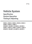
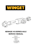
SB4253E02
Jan. 2008
Power Train
Specification
System Operation
Testing & Adjusting
D20S-5, D25S-5, D30S-5, D33S-5, D35C-5
G20E-5, G25E-5, G30E-5
GC20E-5, GC25E-5, GC30E-5, GC33E-5
G20P-5, G25P-5, G30P-5, G33P-5, G35C-5
GC20P-5, GC25P-5, GC30P-5, GC33P-5
Important Safety Information
Most accidents involving product operation, maintenance and repair are caused by failure to observe basic
safety rules or precautions. An accident can often be avoided by recognizing potentially hazardous situations
before an accident occurs. A person must be alert to potential hazards. This person should also have the
necessary training, skills and tools to perform these functions properly.
Read and understand all safety precautions and warnings before operating or performing lubrication,
maintenance and repair on this product.
Basic safety precautions are listed in the “Safety” section of the Service or Technical Manual. Additional
safety precautions are listed in the “Safety” section of the owner/operation/maintenance publication.
Specific safety warnings for all these publications are provided in the description of operations where
hazards exist. WARNING labels have also been put on the product to provide instructions and to identify
specific hazards. If these hazard warnings are not heeded, bodily injury or death could occur to you or other
persons. Warnings in this publication and on the product labels are identified by the following symbol.
WARNING
Improper operation, lubrication, maintenance or repair of this product can be dangerous and could result
in injury or death.
Do not operate or perform any lubrication, maintenance or repair on this product, until you have read and
understood the operation, lubrication, maintenance and repair information.
Operations that may cause product damage are identified by NOTICE labels on the product and in this publication.
DOOSAN cannot anticipate every possible circumstance that might involve a potential hazard. The warnings in
this publication and on the product are therefore not all inclusive. If a tool, procedure, work method or operating
technique not specifically recommended by DOOSAN is used, you must satisfy yourself that it is safe for you and
others. You should also ensure that the product will not be damaged or made unsafe by the operation, lubrication,
maintenance or repair procedures you choose.
The information, specifications, and illustrations in this publication are on the basis of information available at the
time it was written. The specifications, torques, pressures, measurements, adjustments, illustrations, and other
items can change at any time. These changes can affect the service given to the product. Obtain the complete and
most current information before starting any job. DOOSAN dealers have the most current information available.
1
Index
Specification
Testing and Adjusting
Torque Converter.............................................. 5
Forward and Reverse Control Group................. 5
Transmission Solenoid...................................... 5
Forward / Reverse Clutch Elements .................. 6
Valve Block Elements ....................................... 7
Valve Spring in Transmission Bearing Plate ...... 8
Tightening Torques ........................................... 9
Transmission .................................................... 9
Final Drives and Wheels ................................. 11
Drive Tire Installation ...................................... 12
Drive Wheel Installation .................................. 13
Drive Axle Mounting Group ............................. 14
Troubleshooting...............................................38
Transmission Pressure Test ............................44
Converter Stall Test.........................................46
Maintenance....................................................48
Electric Control System Tests ..........................50
Inching Pedal Adjustment ................................56
Adjustments on Drive axle ...............................58
System Operation
General Information ........................................ 15
Torque Converter............................................ 16
Transmission .................................................. 17
Transmission Control Valve ............................ 31
Drive Axle ....................................................... 35
Power Train
3
Index
Specification
Forward and Reverse Control
Group
Torque Converter
(1) Torque for screws (four) that hold clamp to hand
control switch………..3.4 to 3.9 N·m (30 to 35 lb·in)
(2) Torque for bolts (two) that hold clamp to steering
column……………….2.8 to 3.4 N·m (25 to 30 lb·in)
(1) Torque for six bolts that hold torque converter drive
plate to the flywheel ........... 45 ± 7 N·m (33 ±5 lb·ft)
Apply a bead of LOCTITE NO.242 Sealant to inner
radius of the clamp, prior to assembly.
Transmission Solenoid
Valve block elements located on top of transmission
housing…………………………………9.7 to 10.3 ohms
For additional solenoid and valve group
specifications see section “Valve block elements”
Power Train
5
Specifications
Forward / Reverse Clutch
Elements
New 0.5mm (0.0197 In)
2.2 0.08
(0.0866 0.0031 In)
New
Snap ring
Wom 0.35mm(0.0138 In)
minimum
a) Outer clutch Disc
d) Piston return spring
Length under test force ................ 23.1 mm (0.91 in)
Test force ........................969.9 ±5 N (218.0 ± 11 lb)
Free length after test (nominal) ......... 51 mm (2.0 in)
Outside diameter.......................... 95.5 mm (3.74 in)
3 0.05mm (0.1181 0.0020 In)
e) Clearance between piston and pressure disc
..................................................... 1.5 mm (0.059 in)
b) Inner clutch Plate
2 0.05mm (0.0787 0.0020 In)
3 0.15mm (0.1181 0.0059 In)
c) Bend plate
Inside diameter................................. 60mm (2.36 in)
Outside diameter ......................... 122.5mm (4.82 in)
Power Train
6
Specifications
Valve Block Elements
Tighten to 50±7 N·m (37±5 Ib·ft)
Tighten to 0.6 N·m (0.44 Ib·ft) min
SECTION A-A
Tighten to 25±4 N·m (18.5±3 Ib·ft)
Tighten to 5±1 N·m (3.7±1 Ib·ft)
Tighten to 5.5±1.5 N·m
(4±1 Ib·ft)
A
C
Tighten to 50±5 N·m (37±3.7 Ib·ft)
D,E
Tighten to 50±7 N·m
(37±5 Ib·ft)
B
Tighten to 50±7 N·m (37±5 Ib·ft)
D) Spring (outer)
Length under test force…………22.22 mm (0.87 in)
Test force………………...29 to 34 N (6.5 to 7.6 lb)
Free length after test (nominal)….31.7 mm (1.25 in)
Outside diameter………………...11.91 mm (0.47 in)
A) Spring
Length under test force……..…...22.5 mm (0.89 in)
Test force .......................... 42 ± 3.4 N (9.4±0.8 lb)
Free length after test(nominal)...34.65 mm (1.36 in)
Outside diameter…………………...13 mm (0.51 in)
E) Spring (Inner)
Length under test force………..…20.0 mm (0.79 in)
Test force……………...3.34 ± 0.27 N (0.75±0.06 lb)
Free length after test (nominal)...55.93 mm (2.20 in)
Outside diameter………………..7.75 mm (0.305 in)
B) Spring (Inner)
Length under test force……….….26.6 mm (1.05 in)
Test force……………….….37.8 ± 3.0 N (8.5±0.7 lb)
Free length after test (nominal)….48.2 mm (1.90 in)
Outside diameter………………….10.8 mm (0.43 in)
C) Spring (outer)
Length under test force…………...26.6 mm (1.05 in)
Test force…………………..75.6 ± 6.0N (17.0±1.3 lb)
Free length after test (nominal)… 49.2 mm (1.94 in)
Outside diameter………………. .15.24 mm (0.60 in)
Power Train
7
Specifications
Valve Spring in Transmission Bearing Plate
Tighten to 45 N·m (33.2 Ib·ft)
Converter Inlet Valve
A
2-Springs
Tighten to 45 N·m (33.2 Ib·ft)
Converter Outlet Valve
A) Spring
Length under test force…………….30 mm (1.18 in)
Test force…………….......18.1 ± 1.8 N (4.07±0.4lb)
Free length after test(nominal)...43.25 mm (1.70 in)
Outside diameter…………………10.7 mm (0.42 in)
Power Train
8
Specifications
Tightening Torques
Transmission
Power Train
9
Specifications
Power Train
10
Bolt 28 N m (20.7 Ib ft)
Apply Loctite 242 to thread
Bolt 115 N m (84.9 Ib ft)
Apply Loctite 242 to thread
Bolt 115 N m (84.9 Ib ft)
Apply Loctite 242 to thread
_8 N m (59.0+
_5.9 Ib ft)
Bolt 80+
Adjust to
(Slightly Oiled)
19.6 N m (14.5 Ib ft) drag
(See Instructions)
Shims
(See Instructions)
Grease Bearing
Bolt 285 N m (210.3 Ib ft)
With Molycote BR2
Apply Loctite 242 to thread
Nut 50 N m (36.9 Ib ft)
(See Instructions)
Spacer and Shims
(See Instructions)
Nut 150 N m (110.7 Ib ft)
Apply Loctite 242 to thread and face
Drive axle
Specifications
Final Drives and Wheels
D, G Model Trucks
Dual Drive wheels
GC Model Trucks
1
1
2
2
3
4
3
4
5
5
6
Oil Cooled Disc Brake Type
Oil Cooled Disc Brake Type
(1) Apply LOCTITE NO.242 Thread Lock to threads of
spindle bolts.
Torque for bolts that hold spindle to drive axle
housing ....................115 ± 14 N·m (85 ± 10 lb·ft)
(1) Apply LOCTITE NO.242 Thread Lock to threads of
spindle bolts.
Torque for bolts that hold spindle to drive axle
housing……………..115 ± 14 N·m (85 ± 10 lb·ft)
(2) Use a crisscross procedure to tighten nuts.
(2) Torque for wheel mounting bolts ....270 ± 25 N·m
........................................................ (200 ± 20 lb·ft)
(a) Torque for single drive wheel mounting.
nuts....................644 ± 34 N·m (470 ± 25 lb·ft)
(b) Torque for inner and outer dual drive wheel
mounting nuts ....644 ± 34 N·m (470 ± 25 lb·ft)
(3) Wheel bearing adjustment :
(a) Tighten wheel bearing nut to 135 N·m (100lb·ft)
while the wheel is turned in both directions.
(b) Loosen the nut completely. Tighten the nut
again to 50 ± 5 N·m (37 ± 4 lb·ft).
(c) Bend a tab of the lockwasher into a groove of
the wheel bearing nut.
(3) Torque for bolts that hold adapter assembly to hub
................................ 285 ± 13 N·m (210 ± 10 lb·ft)
(4) Wheel bearing adjustment :
(a) Tighten wheel bearing nut to 135 N·m(100 lb·ft)
while the wheel is turned in both directions
(b) Loosen the nut completely. Tighten the nut
again to 50 ± 5 N·m (37 ± 4 lb·ft).
(c) Bend a tab of the lockwasher into a groove of
the wheel bearing nut.
(4) Torque for bolts that hold cover to axle housing
…………………………...55 ± 10 N·m (40 ± 7 lb·ft)
(5) Apply Loctite No.515 Sealant to the axle flange and
cover on the contact area.
(5) Torque for bolts that hold cover to axle housing .....
.....................................55 ± 10 N·m (40 ± 7 lb·ft).
(6) Apply Loctite No.515 Sealant to the axle flange or
spacer and cover on the contact area.
Power Train
11
Specifications
Drive Tire Installation
GC20, GC25 Models
GC30, GC32 Models-Wide Axle
WARNING
The drive tire must be installed as shown below.
Failure to do so will decrease the stability of the
truck, and can cause injury to the operator.
GC20, GC25 Models
Install the tire so that the edge of the tire is even with
the outside edge of the wheel.
GC30, GC32 Models
GC30, GC32 Models-Narrow Axle
Narrow Axle :
Install the tire so there is distance (X) between the
edge of the tire and the inside edge of the wheel.
Distance(X) is……………37 ± 1 mm (1.46 ± 0.04 in)
Wide Axle :
Install the tire so there is distance (x) between the
edge of the tire and the outside edge of the wheel.
Distance(X) is....................37 ± 1 mm (1.46 ± 0.04 in)
.
Power Train
12
Specifications
Drive Wheel Installation
D, G Model Trucks
GC Model Trucks
1
1
(1) Tighten wheel mounting bolts to a torque of
……………………….644 ± 34 N·m (470 ± 25 lb·ft)
Use a crisscross procedure to tighten nuts.
(1) Tighten wheel mounting bolts to a torque of
……………………….270 ± 25 N·m (200 ± 20 lb·ft)
Power Train
13
Specifications
Drive Axle Mounting Group
1
Special shoulder Bolt
Chassis
Standard Bolt
Drive
Axle
Housing
2
(1) Torque for two nuts that hold the axle to the
chassis……………..…488 ± 27 N·m (360 ± 20 lb·ft)
(2) Torque for two nuts that hold the axle to the
chassis.......... ..…..….488 ± 27 N·m (360 ± 20 lb·ft)
Power Train
14
Specifications
System Operation
General Information
3
4
1
Power Flow
(1) Drive axle.
(2) U-joint.
(3) Transmission. (4) Engine.
The basic components of the power train are engine
(4), Transmission (3), U-Joint(2), Drive axle(1) and the
final drives and wheels.
Power from yoke of drive axle is sent through a spiral
bevel gear set to the differential.
The differential sends power out through the axles to
the final drives and wheels.
Two axle shafts connect the differential to two final
drives. The drive wheels are mounted to the final
drives.
Power from the engine goes through the flywheel into
the torque converter. Power then flows through a
transmission (3) and U-joint(2) to yoke of
drive axle(1).
The transmission has two hydraulically operated clutch
packs that are spring released.
The transmission has one speed in forward and one
speed in reverse.
Power Train
15
Systems Operation
The torque converter has four main parts : housing (4),
impeller(pump) (3), turbine(1) and stator(2). The
housing is connected to the engine flywheel through a
flexplate. Impeller (3) and housing (4) are welded
together and turn with the engine flywheel at engine
speed and in the direction of engine rotation. Turbine
(1) turns the transmission input shaft. Stator (2) is
installed stationary on stator support (5) by a
freewheel clutch that allows one way rotation of the
stator.
Torque Converter
4
2
The hub, which is part of impeller (3), fits into the
transission oil pump. The turning impeller (3) rotates
the pump to supply oil for the operation of the torque
converter and transmission
6
When the engine is turning, oil flows through the
converter to lubricate and cool it. With the
transmission in neutral, the impeller, turbine, stator
and oil are all turning together in a direct fluid coupling.
The turbine/impeller speed ratio is 1/1.
5
Once a direction is selected the direct fluid coupling no
longer exists, the turbine/impeller speed ratio changes
(the turbine will be turning slower than the impeller).
When this happens the impeller outlet pressure to
turbine inlet pressure changes. This causes the oil
flow in the torus (fluid path containing the impeller,
turbine and stator) to gain momentum.
1
3
As impeller (3) turns, it increases the energy state of
the oil and directs the oil to the outside diameter of
converter housing (4). Oil leaving impeller (3) is
directed to turbine (1) where much of the oil? energy is
absorbed by turning the turbine. The pressure and
flow change in the torus becomes torque and speed at
the turbine and transmission input shaft.
Torque converter
(1) Turbine. (2) Stator. (3) Impeller. (4) Housing.
(5) Stator support. (6) Stator clutch.
Oil follows the turbine blades inward toward the center
of the converter. When the turbine/impeller speed ratio
is less than .85/1, oil is directed against the concave
side of stator (2) with enough force to stop its one way
rotation and lock the freewheel clutch.
There is no direct mechanical connection between
engine and the transmission. Power from the engine is
transferred through the torque converter, which
hydraulically connects the engine to the transmission.
Transmission drive train oil is used to turn the turbine
and transmission input shaft.
Most of the energy from the oil that strikes the turbine
is used to turn the turbine, but some energy is left over.
Torque multiplication comes about because the locked
stator (2) directs this left over oil back to impeller (3) in
the same direction as the impeller rotation. This
energy force of the oil increases the torque on the
turbine and transmission input shaft. During operation,
this cycle is repeated over and over.
When the lift truck works against a load, the torque
converter can multiply the torque from the engine and
send a higher torque to the transmission.
Without the stator, oil leaving the turbine is travelling in
a direction that is against impeller rotation. Torque
multiplication is only possible because of the stator.
Power Train
16
Systems Operation
Transmission
11
3
9A
10
2
1
4
9
16
5A
6
14
5
15
14A
8
7
13
12
(1) TC Housing. (2) TM Bearing Plate. (3) TM Housing. (4) Torque Converter. (5) Input Shaft. (5A)Input Shaft Gear.
(6) Oil Pump. (7) Forward Gear. (8) Forward Clutch. (9) Reverse Shaft. (9A) Reverse Shaft Gear. (10) Reverse Clutch.
(11) Reverse gear. (12) Output gear. (13) U-joint. (14) Quill Shaft. (14A) Coupling. (15) PTO Pump. (16) Axle Lubrication
Pump.
The Transmission consists of 3 sections:
The reverse shaft (9) carries the reverse shaft gear
(9A), the reverse clutch (10) and the reverse gear (11)
which is in mesh and drives the output gear (12) when
the reverse clutch (10) is selected.
The quill shaft (14) is splined to the torque converter
and therefore rotates with engine speed and direction.
A coupling (14A) connects the PTO pump (15) to the
quill shaft (14).
The axle lubrication (16) pump engages in and is
driven by the reverse shaft. It always operates when
the engine rotates, but rotating speed varies with
torgue converter output.
a) TC housing (1) which contains torque converter (4)
and the oil pump (6) and its housing. Tangs on the
TC neck engage in and drive the pump.
b) Bearing plate (2) which contains the rear bearings
of input, reverse shaft and output gear and the oil
supply channels. The oil channels are sealed by
the front TC housing wall.
c) Transmission housing (3) containing input shaft (5),
forward clutch (8), forward gear (7), reverse shaft (9),
reverse clutch (10), reverse gear (11), output gear (12)
and parking brake. The input shaft engages in and is
driven by the TC turbine hub spline and rotates in
same direction as
the engine. It carries an input
shaft gear (5A) which is in mesh and drives the
reverse shaft gear (9A), the forward clutch (8) and the
forward gear (7), which is in mesh and drives the
output gear, when the forward clutch (8) is closed.
Power Train
17
Systems Operation
Transmission Power Flow – Forward
With the transmission control in forward, which will
pressurize the forward clutch (8), power will flow from
the engine through the torque converter to drive the oil
pump (6) and the input shaft (5), also the quill shaft
(14). Since the forward clutch (8) locks the forward
gear (7) to the input shaft, the power flows through the
forward clutch (8), the forward gear (7) to output gear
(12) which is in mesh with the forward gear. The ujoint (13) which is splined to the output gear will
transmit power to the axle.
Power Train
18
Systems Operation
Transmission Power Flow – Reverse
With the transmission controls in reverse, which will
pressurize the reverse clutch (10), power will flow from
the engine through the torque converter to drive the oil
pump (6) and the input shaft (5) also the quill shaft
(14). Since the reverse clutch (10) is closed, power will
flow through input shaft gear (5A) which is in mesh
and drives reverse shaft gear (9A) and reverse shaft
(9). The reverse gear (11) which is locked to the
reverse shaft by the reverse clutch (10) is in mesh and
drives the output gear (12). The U-joint, which is
splined to the output gear will transmit power to the
axle.
Power Train
19
Systems Operation
Transmission Lubrication Schematic
Oil Cooler
TC
Relieve
Valve
Oil for lubrication of the clutch shaft bearings and
cooling the clutch discs and plates comes from the
outlet passage of oil cooler. Lubrication oil is also
splashed inside the transmission case. Lubrication oil
is especially important for cooling the clutches.
High temperatures can be caused during repeated
shifting of the lift truck.
Power Train
20
Systems Operation
Transmission Hydraulic System
(1) Transmission Oil Sump. (2) Oil Pump. (3) Primary Filter. (4) Main Valve. (5) Orifice. (6) Inching Valve. (7) Modulating Valve.
(7A) Load Piston. (7B) Modulating Valve Orifice. (8) Selector Valve. (9) Solenoid Valve Forward. (10) Solenoid Valve Reverse.
(11) Forward Clutch. (12) Reverse Clutch. (13) Relief Valve. (14) Torque Converter. (15) Relief Valve. (16) Converter Bypass.
(17) Oil Cooler. (18) Torque Converter Supply Bypass.
Power Train
21
Systems Operation
The transmission hydraulic system is explained in
three sections. The first section is the oil pump, filter,
torque converter and oil cooler systems. The second
section is the transmission lubrication system. The
third section is the transmission hydraulic control
system which controls the lift truck direction control.
4
Pump, Filter, Torque Converter and
Oil Cooler Systems
6
The oil for the operation and lubrication of the
transmission is made available by pump (2). The
pump is located in the torque converter housing and is
driven by Tangs on the torque converter neck.
7
Oil sump (1), for the transmission, is in the bottom of
the transmission case. Oil from reservoir flows through
the strainer and internal channels to the suction side of
positive displacement pump .
8
10
Oil from pump (2) flows to primary oil filter (3). If there
is a restriction in the oil filter or if the oil is cold and
thick, a bypass valve in the filter will open. The
difference in pressure at which the bypass valve will
open is 124 ± 7 kPa (18 ± 1 psi). From the primary oil
filter, the oil flows on to main relief valve (4). In the
spool of main relief valve there is a bypass (18). The
purpose of this bypass is to supply lubrication and
coolant oil to the torque converter at low speeds and
especially during hot oil conditions. Converter relief
valve (13) protects the torque converter from oil
pressure higher than 670 kPa (97 psi), such as during
cold oil start-ups. At this pressure, the oil is released
back to the reservoir. Converter inlet passage has
converter bypass orifice (16). The purpose of this
orifice is to prevent too much of a pressure load on the
torque converter by allowing some of the oil to bypass
the converter. In converter outlet passage, there is
cooler bypass valve (15). Cooler bypass valve (15) will
release oil back to the reservoir if the oil pressure
reaches 400 kPa (58 psi). This can happen if the oil
cooler has a restriction or if the oil is cold and thick.
9
The basic components of the hydraulic system for
operating the transmission are transmission oil sump
(1), oil pump (2), primary oil filter (3), valve block,
containing main valve (4), orifice (5), inching valve (6),
modulating valve (7), selection valve (8), forward and
reverse solenoid valves (9,10), forward clutch (11),
reverse clutch (12), torque converter (14) with relief
valves (13,15), bypass (16) and oil cooler (17). The
pump is located in the torque converter housing, and
valve block is located on top of transmission, the filter
is located on the right hand of the transmission
housing.
Power Train
22
Systems Operation
Power Train
23
Systems Operation
Neutral Position
When the transmission is in NEUTRAL position with
the engine running, oil is pulled from reservoir and the
strainer assembly (1) to pump (2). From there, pump
oil flows through the primary filter (3) to main relief
valve (4). Oil will also flow through orifice (18) to
lubricate the torque converter during hot, low speed
conditions.
When the pump pressure reaches 895 kPa (130 psi),
relief valve spool (4A) will move to the left side and
most of the pressure oil flows to the torque converter.
Spool will move left and right to maintain 895 kPa (130
psi). Oil can also bypass the torque converter through
converter bypass orifice (16). The purpose of orifice
(16) is to prevent too much of a pressure load being
put on the torque converter.
Oil flows from the torque converter through a passage
to oil cooler (17). Oil then flows back to transmission to
cool and lubricate the clutches and shaft bearings.
In NEUTRAL position, the remaining pressure oil flows
from main relief valve (4) to inching valve (6).
Without inching (inching pedal up and valve in), oil
flows around and through the center of spool (6A) to
the bottom of the spool. The oil, at the bottom, pushes
the spool to the position shown. Oil flows around the
lands of the spool and through a passage to
modulating valve (7).
In NEUTRAL position, forward solenoid (9) and
reverse solenoid (10) are OFF. Pump oil flow is
blocked at the solenoids. Oil cannot flow through oil
passage to the forward or reverse selector spool.
Pump oil pressure is felt at slugs. This forces forward
selector spool to the right and reverse selector spool
to the left. With the spools in this position, forward
clutch (11) and reverse clutch (12) are open to drain.
Most of the oil still flows through the lube circuit.
Power Train
24
Systems Operation
Power Train
25
Systems Operation
Forward Direction
When the transmission is in FORWARD, the oil flow
from the reservoir, through the pump, primary filter,
torque converter and oil cooler circuits will be the
same as explained in NEUTRAL position.
Oil will flow from the main relief valve to inching valve
(6). Without inching (inching pedal up and valve in), oil
flows around and through the center of reducing spool
(6A) to the bottom of the spool. The oil, at the bottom,
pushes the spool up to the position shown. Oil flows
around the lands of the spool and through a passage
to modulating valve group (7).
In FORWARD, forward solenoid (9) is ON, so pump oil
is sent to the forward selector spool through oil
passage. Forward selector spool (8A) moves to the
right, causing reverse selector spool (8B) to move to
the right also.
With the reverse spool in this position, reverse clutch
(12) is open to drain, Forward selector spool (8A)
opens forward clutch (11) to pump oil. This also opens
reverse selector spool (8B) to drain through oil
passage. Forward clutch (11) will fill with pump oil.
Once filled, oil pressure begins to build up. Pump oil
goes through orifice (7B) and moves load piston (7A)
to the left as pump pressure increases. Oil pressure
increases as the load piston moves further to the left.
The pressure increases to the control pressure of 895
kPa(130 psi). Forward clutch(11) will now be fully
engaged. Modulating valve assembly(7) will now
shuttle between pump oil and drain to maintain clutch
pressure. Clutch fill time takes 0.4 seconds and
pressure increase takes 0.7 seconds.This approximate
1.1 second clutch fill and pressure rise time, gives a
cushion engagement of forward clutch (11).
Power Train
26
Systems Operation
Power Train
27
Systems Operation
Reverse Direction
When the transmission is in REVERSE, the oil flow
from the reservoir, through the pump, primary filter,
torque converter and oil cooler circuits will be the
same as explained in NEUTRAL position.
Oil will flow from the main relief valve to inching valve
(6). Without inching (inching pedal up and valve in), oil
flows around and through the center of reducing spool
(6A) to the bottom of the spool. The oil, at the bottom,
pushes the spool up to the position shown. Oil flows
around the lands of the spool and through a passage
to modulating valve group (7).
In REVERSE, reverse solenoid (10) is ON, so the
pump oil is sent to the reverse selector spool through
an oil passage. Reverse selector spool (8B) moves to
the left, causing forward selector spool (8A) to move to
the left also.
With the forward selector spool in this position, forward
clutch (11) is open to drain. Reverse selector spool
(8B) opens reverse clutch (12) to pump oil. This also
opens forward selector spool (8A) to drain through
passages. Reverse clutch (12) will fill with pump oil.
Once filled, oil pressure begins to build up. Pump oil
goes through orifice (7A) and moves load piston (7A)
to the left as pump pressure increases. Oil pressure
increases as the load piston moves further to the left.
The pressure increases to the control pressure of 895
kPa(130psi). Reverse clutch (12) will now be fully
engaged. Modulating valve assembly(7) will now
shuttle between pump oil and drain to maintain clutch
pressure. Clutch fill time takes 0.4 seconds and
ressure increase takes 0.7 seconds. This approximate
1.1 second clutch fill and pressure rise time, gives a
cushion engagement of reverse clutch (12).
Power Train
28
Systems Operation
Power Train
29
Systems Operation
Forward Direction During Inching
When the transmission is in FORWARD (or
REVERSE) during INCHING, the oil flow from the
reservoir, through the pump, filter, torque converter
and oil cooler circuits will be the same as explained in
NEUTRAL position.
Oil will flow from the main relief valve through a
passage, to inching valve (6). Inching valve (6) lets the
operator control the oil pressure to forward clutch (11)
between 280 and 0 kPa (40 and 0 psi), which permits
a partial engagement of the clutch. Through the use of
the inching valve, the lift truck can move slowly while
the engine is at higher speeds. This lets the operator
move the lift truck slowly up to a load while the mast is
raised rapidly.
When the operator pushes the inching pedal part of
the way down, inching plunger (6B) moves out of the
inching valve. This takes away some of the spring
force between plunger (6B) and reducing spool (6A). It
also removes the balance condition between the pump
pressure, at the bottom of spool (6A), and the spring
force. Reducing spool (6A) moves to the right, which
causes a restriction for the pump oil flow. The
pressure drops from 895 kPa (130 psi) to 280 kPa (40
psi). The pressure can drop further depending on the
position of plunger (6A). Pressure reduces as plunger
(6A) is moved out (as the inching pedal is pushed
down).
This reduced pressure flows to selector valve group
(8). The oil will flow through the valve as explained in
forward direction. The reduced (inching) pressure will
flow through a passage to partially engage forward
clutch (11). This reduced pressure permits slippage of
the forward clutch plates and discs. Therefore, the
truck will have an operator controlled movement. The
amount of oil pressure to clutch (11) depends on the
position of inching plunger (6A). As the plunger is
pulled out completely (inching pedal all the way down)
clutch pressure will drop to 0 kPa (0 psi). The forward
clutch will be disengaged at approximately 65.5 kPa
(9.5 psi).
Power Train
30
Systems Operation
Transmission Control Valve
Basic Control Schematic
DR
DR
DR
FWD
CLUTCH
REV
CLUTCH
SOLENOID
SOLENOID
DR
DR
DR
PUMP
The control schematic is shown below. The system
consists of 2 valve bores:
1. Modulating valve
2. Forward and reverse selector valves
Power Train
31
Systems Operation
Modulating valve function
SPRING
MODULATING VALVE
LOAD PISTON
ORIFICE
DR
REACTION PLUG
DR
DR
FLOW TO SELECTOR
SPOOLS
PUMP
Figure 1
If Force 1 is too large then the valve would be forced
to the right, opening the clutch circuit to supply,
and increasing the value of Force 2 so it balances
Force 1. By regulating clutch pressures between
supply and drain, valve forces are balanced.
The modulating valve consists of 5 basic elements:
1. Orifice
2. Springs
3. Load piston
4. Modulating valve
5. Reaction slug
The function of the modulating valve is to control
clutch pressure during a shift. It allows the clutch
pressure to raise gently to the maximum transmission
pressure in order to provide a smooth clutch
engagement and a good shift feel for the vehicle
operator.
There are two forces acting on the modulation valve:
Force 1 = Pressure (load piston) / Area 1
Force 2 = Pressure (clutch) / Area 2
In order for the modulating valve to stay in a balance
position Force 1 must be equal to Force 2.
If for example Force 2 is too large (clutch pressure is
too large) then the valve will be forced to the left,
shutting off supply and opening the clutch and slug
pressure to drain, and reducing Force 2.
Power Train
32
Systems Operation
Modulating valve movement during clutch fill
Modulation of clutch to top pressure
Figure 3
Figure 2
MODULA TION
When a new direction is selected by the operator, the
selector spools open up a circuit to the new clutch
piston. System pressure drops as the new clutch
piston is stroking. This drop in supply pressure causes
a force imbalance on the modulating valve / reaction
slug pressure becomes smaller. Since Force 1 is still
the same, Force 1 forces the modulating valve to the
right until the end of the modulating valve opens the
load piston cavity to drain.
Figure 4
The load piston oil dumps to drain and the load piston
immediately moves to the right (shown in fig.2).
This action is called "load piston reset". It happens
very quickly in comparison to the time needed for the
clutch piston to fully stroke. Therefore the modulating
valve and load piston are ready to start controlling the
clutch pressure in a smooth upward manner once the
clutch piston finishes stroking.
As long as reaction slug pressure is greater than load
piston pressure, oil will flow across the orifice from
Area 2 to Area 1. As oil flows to the load piston the
springs will continue to compress, allowing the load
piston to move to the left. As the load piston moves to
the left the spring force increases and load piston
pressure increases.
As press (LP) increases the modulating valve will
cause a corresponding increase in clutch pressure in
order to keep the forces balanced. In simple terms as
the load piston strokes to the left the clutch pressure
rises to maximum system pressure.
This controlled rise in clutch pressure takes about 0.7
sec. and is shown in fig.4. It occurs immediately after
the clutch piston completely strokes (end of clutch fill).
Power Train
33
Systems Operation
Selector spools
Figure 5
The selector spool circuits are arranged in such a way
that once a gear (forward or reverse) is selected the
opposite solenoid supply is shut off and drained. This
is done to prevent any electrical or malfunction of the
other solenoid from giving a sudden and unexpected
shift.
In addition the two selector spools are arranged so
they cannot select both forward and reverse at the
same time because they mechanically interfere with
each other.
The selector spools have two areas:
1. Slug area
2. Spool area
The slug cavity is exposed to system pressure all the
time. If the solenoid allows system oil to flow to the
end of the spool and pressurize the spool area then
the spool will move toward the slug because the spool
area is larger than the slug area and the force will be
higher. When the solenoid is closed, pressure to the
spool is reduced. This allows the pressure at the slug
to move the spool away from the slug.
In fig.5 the selector spools are shown with forward
gear selected. Notice that the reverse solenoid supply
is drained through the forward spool.
Power Train
34
Systems Operation
Drive Axle
8
10
9
3
7
6
11
12
4
5,5A,5B,5C
2
1
11
6
12
7
3
9
8
10
(1) Axle Housing. (2) Carrier (3) Brake Housing Left/Right. (4) Pinion. (5) Crown wheel/differential.
(6) Drive Shaft Left/right. (7) Ring Gear/Hub. left/right. (8) Pneumatic Tire Wheel Flange Left/right. (9) Multi-disc brake left/right.
(10) Spindle. (11) Axle Mounting Pads. (12) Mast Mounting Hooks.
The Axle Consists of 4 main sections
a) The carrier housing (2), pinion (4) and crownwheel
with differential assembly (5).
c,d) Hub section left and right with ring gear (7), wheel
flange (8), spindle (10) and multi-disc brake (9).
b) The axle housing with left and right drive shaft (6),
mounting pads (11) and mast mounting hooks (12).
Wheel flange (8) used with pneumatic tire trucks only.
Power Train
35
Systems Operation
Axle power flow
Power is transmitted by the transmission output shaft
to the pinion (4) which meshes with and drives the
crownwheel (5), which is mounted to the differential.
4
5
The differential is part of the drive axle. It is a single
reduction unit with a differential drive gear fastened on
the differential case.
When the lift truck moves in a forward direction and
there is the same traction under each wheel, torgue in
each axle and pinion gears (5B) are balanced. Both
left and right axles roatate the same. During a turn, the
force(traction) that is on the drive wheels is different.
These different forces are also felt on opposite sides
of the differential and cause pinion gears (5) to turn.
The rotation of pinion gears (5) stops or slows the
inside wheel and lets the outside wheel go faster. This
moves the machine through a turn under full power.
The differential gets lubrication from oil thrown about
inside the housing.
The differential is used to send the power from the
transmission to the wheels. When one wheel turns
slower than the other, the differential lets the inside
wheel stop or turn slower in relation to the outside
wheel.
Differential case (5A) has four differential pinion gears
(5B) on the differential pinion shaft. The pinion gears
are engaged with two side gears (5C). The side gears
are splined to the axle shafts.
Power Train
36
Systems Operation
Axle Lubrication Schematic
PUMP
PUMP
3
3
11
22
33
The axle is lubricated by means of the transmissionmounted lubricant pump (2) which gets oil from the
axle suction port (1) and supplies it to the hub section
pressure parts (3) to lubricate and cool hub drive and
multi-disc brakes.
Oil returns to the sump through the drive shaft
bearings and axle housing.
Power Train
37
Systems Operation
3. Actuate the controls for the forward direction and
then for the reverse direction. The actuation must
give the same positive action to the hydraulic
control circuit for clutch engagement in both
directions.
Testing and Adjusting
Troubleshooting
Troubleshooting can be difficult. A list of possible
problems and corrections is on the pages that follow.
4. Remove and check the filter element for loose
particles. Check the strainer behind the
transmission oil plug for foreign material.
This list of problems and probable causes will only
give an indication of where a problem can be and what
repairs are needed. Normally, more or other repair
work is needed beyond the recommendations on the
list. Remember that a problem is not necessarily
caused only by one part, but by the relation of one part
with other parts. This list cannot give all possible
problems and probable causes. The serviceman must
find the problem and its source, then make the
necessary repairs.
a. Particles of friction material give an indication of a
clutch failure.
b. Metallic (metal) particles in the filter give an
indication of wear or mechanical failure in the
transmission and/or axle.
c. Rubber particles give an indication of seal or hose
failure.
Always make visual checks first. Check the operation
of the machine and then check with instruments.
If metal or rubber particles are found, all components
of the transmission hydraulic system must be flushed.
Make a replacement of all parts that show damage.
WARNING
To prevent personal injury, when testing and
adjusting the power train, move the machine to an
area clear of obstructions. There must be
adequate ventilation for the exhaust. When drive
wheels are off the ground for testing, keep away
from wheels that are in rotation.
NOTICE
Before these checks are started, fill the transmission
and axle with oil to the correct level. See the Operation
& Maintenance Manual for the procedure to check
transmission and axle oil level.
Operate the machine in each direction. Make note of
all noises that are not normal and find their source. If
the operation is not correct, make reference to the
troubleshooting chart for "problems" and "probable
causes"
Activate the controls for the FORWARD direction and
then for the REVERSE direction. The modulation will
be seen on pressure gauge in the clutch pressure tap
when the shift is made at low idle. The pressure will
increase to 895 kPa (130 psi) when completely filled.
Operate the machine in each direction. Make note of
noises that are not normal and find their source. If the
operation is not correct, make reference to the check
List During Operation for "problems" and "probable
causes".
Visual Checks
1. Check the oil level in the transmission and axle with
the engine running and with the Transmission in
NEUTRAL.
2. Check all oil lines, hoses and connections for leaks
and damage. Look for oil on the ground under the
machine.
Power Train
38
Testing and Adjusting
g. Leakage inside the transmission.
Worn or broken metal seal rings on input
or reverse shaft.
Worn or broken seals around clutch piston.
Modulating valve assemblies stuck
Because of contaminated oil
Check List during Operation
Problem: Engine starts with directional control
switch in FORWARD or REVERSE.
Probable cause:
1. Directional control switch is defective
3. External oil lines are not connected correctly.
Problem: Transmission shifts with parking brake
engaged.
4. Mechanical failure in the transmission.
Probable cause:
Problem: Transmission operates only in
FORWARD.
1. Parking brake switch is defective.
Probable cause:
Problem: Transmission will not stay in gear when
shifted.
1. Forward clutch is locked up.
2. Reverse solenoid valve does not actuate.
Probable cause:
3. Reverse clutch components have damage.
1. Parking brake switch mounting is loose.
a. Leakage caused by worn or broken metal sealing rings.
Problem: Transmission does not operate in either
direction or does not shift.
b. Leakage caused by worn or broken clutch piston.
Probable cause:
c. Failure of shaft seal ring.
1. Problems in the electrical circuit (directional control)
Problem: Transmission operates only in REVERSE.
Probable cause:
a. Open circuit between ignition switch and directional control switch.
1. Reverse clutch is locked up.
b. Defective directional control switch.
2. Forward solenoid valve does not actuate.
c. Defective wiring harness between directional
control switch and transmission.
3. Forward clutch components have damage.
a. Leakage caused by worn or broken metal
sealing rings
d. Shorted wiring harness for the solenoids.
2. Low oil pressure or no oil pressure caused by:
b. Leakage caused by worn or broken seal around
clutch piston.
a. Iow oil, no oil or thick oil.
c. Failure of shaft seal ring.
b. Inching control valve linkage loose, broken or
adjustment is not correct.
Problem: Transmission gets hot.
c. Inching valve reducing spool stuck open.
Probable cause:
d. Failure of the oil pump or a defect in the oil
pump.
1. Restriction in cooling circuit.
2. Oil level too high or too low.
e. Main relief valve stuck open.
3. Core of the oil cooler not completely open.
f. Restriction in the oil flow circuit such as dirty oil
screen.
4. Low pump pressure - worn or damaged pump.
5. Converter one-way clutch worn and slipping.
6. Air mixed in the oil. Air leaks on the intake side of
the pump.
Power Train
39
Testing and Adjusting
7. Low oil flow through converter. Converter relief
valve stuck open (converter bypass orifice plugged)
Check List from Operation Noise
Problem: Noise in NEUTRAL only.
8. Incorrect use of vehicle. Loads are too heavy for the
lift truck.
Probable cause:
9. Too much inching operation (slipping the clutch
plates and discs).
1. Worn one-way clutch in torque converter.
2. Low oil level (pump cavitation).
10. Too much stalling of torque converter.
3. Worn bearing next to pump.
11.Cooler relief valve stuck open, full oil flow does
not go through oil cooler.
Problem: Pump noise not normal
Problem: Clutch engagement is slow or loss of
power during engagement.
Probable cause:
1. A loud sound at short time periods gives an
indication that foreign material is in the
transmission hydraulic system.
Probable cause:
1. Low oil pressure
2. A constant loud noise is an indication of pump
failure.
2. Air mixed in the oil.
a. Air leaks on suction side of pump.
Problem: Noise in the Transmission that is not
normal.
b. Low oil level also causes aeration.
Probable cause:
3. Inching valve linkage adjustment is not correct.
1. Transmission components have wear or damage.
4. Modulating valve assembly leaks or partially stuck.
a. Damaged gears.
Problem: Clutch engagement makes a rough shift.
b. Worn teeth or clutch plates and/or clutch discs.
Probable cause:
c. Slipping clutch plates and disc noise.
1. Modulating valve assembly, load piston and/or
reducing valve stuck.
d. Other component parts have wear or damage.
Problem: Vehicle operates in one direction and
creeps in that direction in NEUTRAL. Engine stalls
when shifted to the other direction.
e. Failure of the thrust washers.
2. Modulating valve assembly makes noise.
Probable cause:
Problem: Constant noise in the Drive axle.
1. Failure of clutch in the direction the lift truck moves.
Clutch discs or plates are warped (damaged) or
held together because of too much heat.
Probable cause:
1. Lubricant not to the specific level.
2. Failure of the modulating valve assembly in the
direction the lift truck moves. The valve assembly
stuck in the engaged position possibly caused by
metal burrs (particles) or oil contamination.
2. Wrong type of lubricant.
3. Wheel bearings out of adjustment or have a defect.
4. Bevel gears not in adjustment for correct tooth
contact.
5. Teeth of bevel gear have damage or wear.
Power Train
40
Testing and Adjusting
6. Too much or too little gear backlash.
2. Loss at bevel input pinion shaft.
7. Loose or worn pinion bearings.
a. Lubricant above specification level.
8. Loose or worn shaft bearings.
b. Wrong kind of lubricant.
9. Loose or worn differential bearings.
c. Restriction of axle housing breather.
Problem: Noise at different intervals.
d. Pinion oil seal worn or not installed correctly.
Probable cause:
Problem: Drive wheels do not turn.
1. Bolts on drive gear not tightened correctly.
Probable cause:
2. Drive gear has a defect (warped).
1. Broken axle shaft.
3. Loose or broken differential bearings.
a. Loose wheel bearings.
4. Bevel gear bearing failure.
b. Axle shaft too short.
Problem: Noise on turns only
2. Side gear or differential pinion broken.
Probable cause:
3. Differential pinion shaft or spider broken.
1. Differential pinion gears too tight on the spider or
the pinion shaft.
Check List from Pressure Test
2. Side gears tight in differential case.
Problem: Low pressure
REVERSE clutches.
3. Differential pinion or side gears have a defect.
4. Thrust washers worn or have damage.
to
FORWARD
and
Probable cause:
5. Too much clearance (backlash) between side gears
and pinion.
1. Inching valve linkage adjustment is not correct.
2. Inching valve reducing spool stuck open.
6. Worn axle shaft assembly gear.
3. Clutch piston seals cause leakages.
7. Hub gear worn.
8. Wheel bearings worn or out of adjustment.
4. Main relief valve setting too low caused by a
defective relief valve spring.
Problem: Leakage of lubricant.
5. Low oil pressure. See Probable Cause for Low Oil
Pressure.
Probable cause:
6. External oil lines are not connected correctly.
1. Loss through hub seals.
7. Modulating valve assembly stuck.
a. Lubricant above specification level.
Problem: Clutch pressure and pump pressure are
high.
b. Wrong kind of lubricant.
Probable cause:
c. Restriction of axle housing breather.
1. Main relief valve is stuck.
d. Hub oil seal installed wrong or has damage.
2. A restriction in the hydraulic circuit.
3. Main relief valve not adjusted properly.
Power Train
41
Testing and Adjusting
Problem: Pressure to one clutch is low.
Problem: High converter charge pressure.
Probable cause:
Probable cause:
1. Clutch piston seal alignment is not correct, oil leaks
through.
1. A plugged converter bypass orifice.
2. A restriction inside the converter assembly.
2. Seal rings on shaft or clutch piston seals are broken
or worn.
3. A plugged oil flow passage.
3. Modulating valve assembly stuck.
Problem: Low converter charge pressure.
Problem: Low pump pressure.
Probable cause:
Probable cause:
1. Converter relief valve stuck open.
1. Low oil level.
2. Main relief valve movement is restricted.
2. Main relief valve movement is restricted.
Problem: Low converter outlet pressure or cooler
inlet pressure.
3. Transmission oil pump is worn.
Probable cause:
4. Inner oil leakage.
1. Low oil pressure.
5. Main relief valve not adjusted properly.
2. Cooler relief valve stuck open.
Problem: Low lubrication
lubrication pressure.
pressure
or
no
Problem: High converter outlet pressure or cooler
inlet pressure.
Probable cause:
Probable cause:
1. Low oil pressure or no oil pressure caused by:
1. Restriction in oil cooler lines or a plugged oil
cooler.
a. Failure of the oil pump or a defect in the oil
pump.
Problem: Low stall speed.
b. Restriction in the oil flow circuit such as a dirty
oil screen.
Probable cause:
c. Inching valve reducing spool stuck open.
1. Engine performance is not correct.
d. Leakage inside of transmission caused by component defects.
2. The one-way clutch of the torque converter does
not hold.
2. Oil cooler has restriction to oil flow.
Problem: High stall speed in both directions.
Problem: High lubrication pressure.
Probable cause:
Probable cause:
1. Low oil level.
1. Restricted external oil lines or internal passages.
2. Air in the oil.
2. External oil lines are not connected correctly.
3. Clutches slip (clutch plates slide in relation to one
another).
4. Torque converter failure.
Power Train
42
Testing and Adjusting
Problem: High stall speed in one direction.
Problem: Modulation spool problems.
Probable cause:
1. There is a leak in the clutch circuit.
1. Slow or no modulation of both clutches
(If only 1 clutch does not modulate correctly then
the problem is either with the selector spool or it is
a problem in the transmission).
2. There is a failure in that clutch assembly (clutch
slipping).
Probable cause:
Problem: Selector spool problems.
1. orifice plugged with debris
1. Transmission stays in neutral, no shift.
2. Modulation valve stuck
Probable cause:
1. Spools mechanically stuck
3. Modulation valve not correctly assembled.
4. Load piston problem
a. Contamination
a. Stuck in bore
b. Case or body not flat
b. Excessive valve / bore clearance
c. Bore / spool worn
c. Missing springs
2. Solenoids not working
5. Porosity in body in the area of load piston cavity
a. O-rings leaking (cut)
b. O-rings missing
2. Modulation time is too quick
c. Ports not machined properly
Probable cause:
d. Contamination in solenoid
1. The upstream orifice (in the oil supply) is not
installed. (The orifice is located in the valve block)
e. Electrical problem
2. The load piston is only moving a small amount
before it sticks. Check the spool to see if it freely
fits in the bore. This check must be made while the
aluminum body is still bolted down to the
transmission.
3. Orifice plugged
a. With debris
b. Bad part
3. The plastic orifice is not installed or the hole in the
plastic housing is too large.
4. Modulation valve stuck in "off" position
5. Modulation valve not correctly assembled.
4. The modulating valve is stuck in an open position.
Check to see if the valve moves freely while the
aluminum body is still bolted down.
2. Transmission will not shift into or out of 1 gear
Probable cause:
1. Spools mechanically stuck (same as above)
5. The springs are not installed or the pin has jammed
the load piston
2. Solenoids not working (same as above)
3. Valve not correctly assembled (same as above)
4. Holes not drilled into case properly
5. Excessive leakage internally in body
a. Porosity in body
b. Selector bore too large
c. Spool too small
d. Slug/spool fit not right.
Power Train
43
Testing and Adjusting
Transmission Pressure Test
Most problems in the hydraulic circuit can normally be
found when the pump pressure is checked. If more
information is necessary, gauges can be installed at
each pressure tap location. Locations of the pressure
taps and procedures for testing are given as follows. If
any of the pressures are not correct, refer to
Troubleshooting For Problems and Probable Causes.
Tools Needed
Pressure Gauge Group
1
WARNING
1. Be sure the transmission control adjustments are
correct before tests are made.
See Inching Pedal Adjustment in Testing and
Adjusting.
To prevent personal injury, when the transmission
is tested, move the truck to a clear area, that is
level. Keep all other personnel away from the lift
truck. Use lifting equipment or a save method to
lift the front of the lift truck until the drive wheels
are off the floor. Put wood blocks or jack stands of
the correct capacity under it to hold it in this
position while pressure tests are performed.
2. Install a tachometer to the engine to show engine
speed during the test.
3. Put a thermistor probe in place of the dipstick in the
transmission oil reservoir.
4. Remove each of the following pressure tap plugs in
the order shown and install the 0 to 2050 kPa (0 to
300 psi) pressure gauge. After the pressure check
is done, remove the gauge and install the plug
again.
When the transmission tests are made, the
transmission oil must be at the correct level. The
pressure given in the chart are taken with the
transmission oil temperature at 49 to 71°C (120 to
160°F). If the oil temperatue is lower than 49°C
(120°F) the oil pressure will be higher than that shown.
If the oil temperature is higher than 71°C (160°F), the
pressure will be lower than that shown.
5. Check pump pressure with the transmission in
neutral at pressure tap (6) on the valve body first. If
it is not correct, then check pump pressure at
pressure tap (1) on the bearing plate.
Raise the front of the lift truck off the floor. Put wood
blocks or jack stands of the correct capacity under it to
hold it in this position while pressure tests are
performed.
a. If the pressure is low at pressure tap (6), but
correct at pressure tap (1), there could be an oil
line restriction or a defective inching valve.
WARNING
Before any pressure tap plugs or connections are
removed, the engine must be stopped with the
transmission controls in NEUTRAL. This will
release hydraulic pressure in the transmission.
NOTE: Pump pressure should be checked at
pressure tap (6) first because pressure tap (6) is
easier to get to than pump pressure tap (1) on the
bearing plate. If pump pressure is correct at
pressure tap (6), it will be correct at pressure tap
(1) also.
For more identification of transmission problems, the
pressures that follow can be checked.
b. If the pressure is low at both locations, see
Problem: Low pump pressure in Troubleshooting.
a. Pump pressure in neutral.
NOTE: Pump pressure is adjusted by adding or
removing shims in the D700296 Plug. The plug is
located in the main relief valve on the valve body.
b. Forward clutch pressure in forward.
6. Check clutch pressure as follows:
c. Reverse clutch pressure in reverse.
a. Check forward clutch pressure at pressure tap
(4) with the transmission in forward. If the
pressure is not correct, see Problem: Low
forward clutch pressure in Troubleshooting.
d. Converter charge pressure in neutral.
e. Converter outlet or cooler inlet pressure in neutral.
f. Lubrication pressure in neutral.
Power Train
b. Check reverse clutch pressure at pressure tap
(5) with the transmission in reverse. If the
pressure is not correct, see Problem: Low
reverse clutch pressure in Troubleshooting.
44
Testing and Adjusting
Pressure Tap Locations – Transmission Control Group
Main Pressure Tap 6
Reverse Pressure Tap 5
Forward Pressure Tap 4
Converter Charge Pressure Tap
Converter Outlet Pressure Tap 2
Temperature Sensor
To Cooler
From Cooler
Lubrication Pressure Tap 7
Power Train
45
Testing and Adjusting
7. Check lubrication pressure at pressure tap (7) with
the transmission in neutral.
Converter Stall Test
NOTE: Make sure that the transmission oil is at the
correct temperature for operation before tests are
made.
a. If lubrication pressure is low, see Problem: Low
lubrication pressure in Troubleshooting.
b. If lubrication pressure is high, see Problem:
High lubrication pressure in Troubleshooting.
The converter stall test is a test to check engine power.
It can also be used to locate a problem in the
transmission or torque converter when the condition of
the engine is known. An engine, which does not have
correct performance, will give an indication of a stall
speed that is not correct. If the engine performance is
correct and the stall speed is not correct, the problem
in the converter or transmission can be found with this
test.
8. Check converter charge (inlet) pressure at pressure
tap (3) with the transmission in neutral.
a. If converter charge pressure is low, see
Problem:
Low converter charge pressure in
Troubleshooting.
NOTE: To check the engine performance, see the
respective engine module. This test checks the
maximum RPM that the engine, at full throttle, can turn
the converter with the turbine held stationary. To hold
the converter turbine, engage the brakes with the
transmission in FORWARD or REVERSE.
b. If converter charge pressure is high, see
Problem:
High converter charge pressure in
Troubleshooting.
9. Check converter outlet or cooler inlet pressure at
pressure tap (2) with the transmission in neutral.
The drive wheels must not turn during the stall test.
Put a heavy load on the forks. Also put the truck in
position against a solid object that will not move (such
as a loading dock). When the tests are made, the
wheel brakes must be engaged with the left foot. The
accelerator pedal can be operated with the right foot.
a. If the pressure is low, see Problem:
Low converter outlet or cooler inlet pressure in
Troubleshooting.
b. If the pressure is high, see Problem:
High converter outlet or cooler inlet pressure in
Troubleshooting.
WARNING
Make tests in a clear level area only. There must
be one operator. Keep all other personnel away
from the lift truck. Check the operation of the
brakes before the tests are made.
NOTE: Do not activate the inching pedal when
pressure checks are made. Check for the pressures
as shown in Transmission Pressure Chart in the
order that follows:
Transmission Pressure Chart
Low idle
Check the high idle setting before the stall test is made.
Set the high idle to the specification, as given in the
respective engine module.
2000 rpm
Shift position - Neutral
Main Line
830 to 1,030, kPa
(120 to 150psi)
895 to 1,100,kPa
(130 to 160psi)
Clutch
0 kPa
(0 psi)
0 kPa
(0 psi)
Lubrication
14 to 70 kPa
(2 to 10 psi)
240 to 345 kPa
(35 to 50 psi)
Converter Chage
70 to 140 kPa
(10 to 20 psi)
590 to 795 kPa
(85 to 115 psi)
Converter Outlet
or Cooler Inlet
25 to 55 kPa
(4 to 8 psi)
250 to 400 kPa
(36 to 58 psi)
NOTE: Make sure that the transmission oil is at the
correct temperature for operation before tests are
made.
1. Connect a tachometer to the engine. Start the
engine. Engage the wheel brakes with the left foot.
2. Put the transmission control lever in FORWARD
and push the accelerator pedal down completely
with the right foot. Read the RPM on the
tachometer, then release the accelerator pedal.
Shift position – Forward or Reverse
Main Line
-
-
Clutch
725 to 860 kPa
(105 to 125 psi)
725 to 965 kPa
(105 to 140 psi)
Lubrication
-
-
Converter Chage
-
-
Converter Outlet
or Cooler Inlet
-
-
Power Train
46
Testing and Adjusting
The stall speed must be the same in FORWARD and
REVERSE. If the stall speed is high in FORWARD and
REVERSE, check the following:
NOTICE
To make sure that the transmission oil does not get
hot, do not hold the transmission in a stall condition for
more than ten seconds. After the transmission is
stalled, put the controls in NEUTRAL and run the
engine at 1200 to 1500 RPM to cool the oil.
a. Check for air in the oil.
b. Check the torque converter and the clutch
pressures according to transmission Pressure
Tests in Testing and Adjusting.
c. If clutch pressure is correct, make an inspection
of the clutch assembly for that direction for
possible damage to clutch components.
3. Repeat the procedure above for the REVERSE
direction.
4. The stall speeds for the different trucks are listed in
the charts that follow:
LIFT TRUCK STALL SPEED
Engine
Max.RPM
RPM±100
RPM±100
Without Power
With Power
Brakes Applied
Brakes Applied
B3.3
1,780
1,680
2,200
4TNV98
1,840
1,740
2,350
4TNE98
1,720
1,620
2,540
1,860
1,760
2,500
1,860
1,760
2,500
1,860
1,760
2,500
2,030
1,930
2,550
2,030
1,930
2,550
2,030
1,930
2,550
Engine
HMC
G420F(E)
LP
HMC
G420F(E)
GAS
HMC
G420F(E)
Dual
GM
G424F(E)
LP
GM
G424F(E)
GAS
GM
G424F(E)
Dual
-
Stall speeds that are low are an indication that the
engine performance is not correct or the one-way
cutch of the torque converter does not hold in reverse
direction. If the one-way clutch has a defect, the stall
speed will probably be more than 800 rpm low.
Power Train
47
Testing and Adjusting
Maintenance
Transmission
Change
Filter
Grease Parking
Brake Lever
Oil Filler And Dipstick
Pin And Nut
Of Parking Brake
Oil Drain Plug
and Suction Strainer
ATTENTION: When changing oil, replace filter and clean suction strainer.
Power Train
48
Testing and Adjusting
Drive Axle
Combined Oil Filler and
Dipstick
Brake Cooling Port
Pump Suction Port
Brake Cooling Port
Oil Drain Plug Port
ATTENTION: Clean suction strainer when replacing oil.
Power Train
49
Testing and Adjusting
Electric Control System Tests
Directional Control Switch Check
1. Put the directional control lever in neutral. Remove
the cover from the front side of front cockpit unit.
Tools Needed
Digital Multimeter
1
NOTE : Refer to Schematic.
Checks on the transmission directional control
electrical circuit can be done with a Digital Multimeter.
All voltage checks are made at the wiring harness
connectors with the ignition switch ON, DO NOT start
the engine. All continuity checks are done with the
ignition switch OFF.
A beginning check of the direction control system
should be performed before testing the individual
components and wiring harness. When the direction
solenoids are energized they become magnetized. By
holding a metal screwdriver next to the solenoids it
can be determined whether they are energized or not.
2. Disconnect harness connector from directional
control switch connector.
Turn the ignition switch ON, DO NOT start the engine.
Release the parking brake. Place the direction control
switch in forward and check the forward solenoid for
magnetism. Do the same for the reverse direction.
z
If the solenoids didn’t energize begin testing the
control system with step 1.
z
If the solenoids did energize, go to step 10.
Directional Control Switch Connector
3. Engage the parking brake and turn the ignition
switch ON, DO NOT start the engine. Put the
multimeter on the 20 volt range.
4. Put the (-) probe on a good ground. Put the (+)
probe on socket 1 of harness connector.
a. If the indication is battery volts, do Step 5.
b. If the indications 0 volts, check the
Forward/Reverse fuse (No.3) located in the fuse
box and check the connecting wires for continuity.
Power Train
50
Testing and Adjusting
5. Turn the ignition switch OFF and put the multimeter
on the 200 ohm range.
Transmission Control Harness Check
9. Disconnect the connector of Engine harness from
the connector of transmission harness. Check the
continuity of engine harness from one end to the
other. Repair or replace the wiring harness if there
is no continuity.
6. Check continuity between pins 4 and 7 of directional
switch connector with the switch in neutral.
Forward and then reverse the positions. There
should be continuity in neutral and no continuity in
forward and reverse.
a. If the above checks are correct, do Step 7.
Transmission Solenoids Visual Check
b. If any of the above checks are not correct,
replace the directional control switch.
10. A visual check can be done to see if the solenoid
plungers are moving.
Remove the modulating valve assemblies from the
transmission
7. Check continuity between pins 1 and 2 of directional
switch connector in forward and then neutral
position. There should be continuity in forward and
no continuity in neutral. While the continuity is
checked in forward position, move the lever back
and forth (but stay in forward position) to see if the
resistance goes up or down. The resistance should
be constant.
11. Turn the ignition switch ON, DO NOT start the
engine. Release the parking brake.
12. Put the directional control switch in neutral.
Both solenoid plungers should be flush with the
solenoid.
a. If the above checks are correct, do step 8.
13. Put the directional control switch in forward and
then reverse.
The plunger of the solenoid that is activated should
move in approximately 3.18mm(.125 in).
b. If the above checks are not correct, replace the
directional control switch.
8. Check continuity between pins 1 and 3 of directional
switch connector (1) in reverse and then neutral
positions. There should be continuity in reverse
and no continuity in neutral. While the continuity is
checked in reverse position, move the lever back
and forth (but stay in reverse position) to see if the
resistance goes up or down. The resistance should
be constant.
14. If the solenoid plungers do not move as explained
in Steps 12 and 13, replace the defective solenoid.
15. If the solenoid plungers are good, the modulating
valves could be stuck or there is mechanical failure
in the transmission.
a. If the above checks are correct, do Step 9.
b. If any of the above checks are not correct,
replace the directional control switch.
Power Train
51
Testing and Adjusting
Transmission Directional Control Schematic for G15/35S-5
Power Train
52
Testing and Adjusting
Transmission Directional Control Schematic for D15/35S-5 (Cummins Engine A2300 / B3.3)
Power Train
53
Testing and Adjusting
Transmission Directional Control Schematic for D20/33S-5, D35C-5 (Yanmar Engine 4TNV98)
Power Train
54
Testing and Adjusting
Transmission Directional Control Schematic for D20/33S-5, D35C-5 (Yanmar Engine 4TNE98)
Power Train
55
Testing and Adjusting
Inching Pedal Adjustment
WARNING
To prevent personal injury, when the inching pedal
is adjusted, move the truck to a clear area that is
level. Keep all other personnel away from the lift
truck. Use lifting equipment or a safe method to lift
the front of the lift truck until the drive wheels are
off the floor. Put wood blocks or jack stands of the
correct capacity under it to hold it in this position
while the inching pedal is adjusted.
To check the inching valve adjustment and operation,
do the procedure that follows :
WARNING
When this procedure is used, the lift truck must be
in an area clear of obstructions. There must be
one operator with all other personnel away from
the lift truck. Check the operation of the brakes
before the test is made.
2. Raise the front of the lift truck off the floor. Put wood
blocks or jack stands of the correct capacity under it
while the inching pedal is adjusted.
1. With the engine at idle speed, put the transmission
in FORWARD.
3
2
14
1
Inching Pedal Adjustment
(1) Lug. (2) Bolt. (3) Nut.
Inching Operation Test
(1) Inching pedal.
3. Start the engine and put the transmission
FORWARD.
2. Slowly push down on inching pedal (1) until the
movement of the brake pedal causes the brake
discs to make contact (small drag) with the brake
plates.
4. With the drive wheels turning, depress inching pedal
until the drive wheels stop.
5. Now depress the brake pedal until disc contact is
felt.
3. Increase the engine speed to high idle. The truck
must not move.
6. Loosen nut (3) and adjust bolt (2) to contact lug (1)
that rotates the brake control cross shaft. Tighten
nut (3).
If the operation of the inching valve is not correct, do
the procedure that follows.
7. Check the inching valve operation again.
a. If something is wrong, inspect all points again
one by one very carefully.
1. Adjust and bleed the wheel brakes as shown in the
Vehicle Systems module.
Power Train
56
Testing and Adjusting
The adjusting procedure is as follows. Be sure that the
air bleeding of brake system should be done in
advance.
85.5 1 mm
3. Adjust the height (C) of inching pedal and brake
pedal. (C) should be 110mm at the same level.
(A)
82.5 mm
235 1
mm
(B)
(E)
4. Adjust the gap (D) for engaging brake pedal by
inching pedal. (D) should be approx. 9.5mm.
1. Adjust the length (A) from the spool to the
connection point of yoke. (A) should be 85.5 ± 1mm.
Be sure that 1mm of gap between the piston and
the rod should exist. In case of no gap, it would
result in brake drag or overheating of axle oil. In
case of too loose, the performance of service brake
become lowered.
5. The distance (E) between the shaft center and its
mounting bracket should be 82.5mm.
6. The stroke of inching spool should be 8 ± 1mm.
7. Before doing the truck test, inspect again all
relevant dimensions.
8. Inspect the service brake and then, inching
operation.
2. Adjust the length (B) of rod by fixing the nuts at both
ends. (B) should be 235 ± 1mm.
Power Train
57
Testing and Adjusting
Adjustments on Drive axle
4. Calaulate the shimpack thickness according to the
following formula.
Shimpack thickness = A-(127+B+C)
Example) if A=160.50, B=32.00, C=+0.05
Then, shimpack thickness
=160.50-(127+32.00+0.05) = 1.45mm
Axle, Pinion, crown gear
* To minimize the measuring error, measure
three places at least and average them.
1. Measure the depth from center of diff. carrier to the
seat of pinion bearing cup. (Dimension A)
5. Shims of calculated thickness laid into bearing seat.
2. Measure the width of pinion bearing.(Dimension B)
6. Install bearing cup.
3. Check the etched value on the pinion face.
(Dimension c)
*unit : mm
7. Install crown gear, differential assy and cap lightly.
Power Train
58
Testing and Adjusting
8. Install bearing nuts for the correct cap position and
lightly torque them to achieve bearing preload.
11. When drag is correct, mark position of nuts both
on nuts and bridge.
9. Tap on differential on both sides to achieve correct
bearing cone position, rotate differential (3-5 times).
12. After marking of position remove differential assy.
10. Check drag 19.6 N.m (14.5 lb.ft) on rotating
differential.
Power Train
59
Testing and Adjusting
Installation of Pinion
4. Tap bearing cone to correct position(Rotate pinion
3-5 times)
1. Install cup of rear pinion bearing
5. Assemble yoke and nut and tighten flange nut to
180 ±15 N·m (133±11 lb·ft)
2. Install spacer and shims on pinion (basic thickness
1.5mm (0.059 in)).
6. Measure the rolling torque. The value of rolling
torque should be 1.5~2.0 N·m (1.1~1.5 lb·ft)
7. If the rolling torque exceeds 2 N·m, add one shim
and if it is lower than 1.5 N·m, subtract one shim
3. Install bearing cone.
8. When the adjustment is correct, disassemble the
nut and the yoke. Assemble the oil seal and yoke
again and then tighten the nut to 180 ±15 N·m
(133±11 lb·ft)
Power Train
60
Testing and Adjusting
Adjustment of Crown Wheel
3. Tap on both sides of the differential to achieve
correct position of bearing cups.
1. Torque crown wheel bolts to 80 N·m (59 lb·ft).
4. Check backlash between pinion and crown gear in 3
different positions. Backlash shall be 0.15-0.20 mm
(0.006-0.008 in)
2. Install differential assy., to previously mounted
position (rotate both nuts simultaneously to
maintain bearing preload).
5. Check contact face by rotating pinion in both
directions, hold back crown wheel.
Power Train
61
Testing and Adjusting
9. Position not correct.
6. Check contact area position and correct in
accordance with specification if neccessary.
10. After correct adjustment of contact area secure
differential nut with split pin.
7. Position not correct
8. Correct position.
Power Train
62
Testing and Adjusting
Adjustment of Wheel Bearings
4. Remove wheel nut for lockwasher installation.
1. Assemble outer hub bearing without lockwasher.
5. Install lockwasher and nut.
2. Tighten wheel nut to 135 ± 14 N·m (100±10 lb·ft).
6. Tighten nut to 50 ±5 N·m (37±3 lb·ft).
3. Tap on and rotate hub 3-5 times to achieve correct
bearing position
Power Train
63
Testing and Adjusting